System Release 2.5/3.5/4.0 Service Pack 3 Release Notes … · Roll Back the Enterprise 450 or Sun...
168
4004148 Rev C System Release 2.5/3.5/4.0 Service Pack 3 Release Notes and Installation Instructions
Transcript of System Release 2.5/3.5/4.0 Service Pack 3 Release Notes … · Roll Back the Enterprise 450 or Sun...
4004148 Rev C
System Release 2.5/3.5/4.0 Service Pack 3 Release Notes and Installation Instructions


Please Read
Important
Please read this entire guide. If this guide provides installation or operation instructions, give particular attention to all safety statements included in this guide.
Notices
Trademark Acknowledgments
Cisco and the Cisco logo are trademarks or registered trademarks of Cisco and/or its affiliates in the U.S. and other countries. A listing of Cisco's trademarks can be found at www.cisco.com/go/trademarks.
CableCARD is a trademark of Cable Television Laboratories, Inc.
Other third party trademarks mentioned are the property of their respective owners.
The use of the word partner does not imply a partnership relationship between Cisco and any other company. (1009R)
Publication Disclaimer
Cisco Systems, Inc. assumes no responsibility for errors or omissions that may appear in this publication. We reserve the right to change this publication at any time without notice. This document is not to be construed as conferring by implication, estoppel, or otherwise any license or right under any copyright or patent, whether or not the use of any information in this document employs an invention claimed in any existing or later issued patent.
Copyright
© 2007, 2012 Cisco and/or its affiliates. All rights reserved. Printed in the United States of America.
Information in this publication is subject to change without notice. No part of this publication may be reproduced or transmitted in any form, by photocopy, microfilm, xerography, or any other means, or incorporated into any information retrieval system, electronic or mechanical, for any purpose, without the express permission of Cisco Systems, Inc.
4004148 Rev C iii
Contents
About This Guide vii
Chapter 1 Introducing System Release 2.5/3.5/4.0 Service Pack 3 1
Support for Daylight Saving Time Changes ........................................................................ 3 Major Improvements to SR 2.5/3.5/4.0 SP3 ........................................................................ 4
What CRs Are Included in This Service Pack? .................................................................... 5
What Are the Site Requirements? .......................................................................................... 6
What Are the Known Issues? ................................................................................................. 9
Chapter 2 DNCS Pre-Upgrade Procedures 11
When to Complete These Procedures ................................................................................. 13
Plan Which Optional Features Will Be Supported ............................................................ 15 Verify the Integrity of the CDs ............................................................................................. 17
Verify the Integrity of the DBDS Maintenance CD ........................................................... 18
Check Available Disk Space ................................................................................................. 19
Run the Doctor Report .......................................................................................................... 20
Examine Mirrored Devices ................................................................................................... 21 Verify DBDS Stability ............................................................................................................ 22
Verify and Back Up the Current Modulator Software ..................................................... 23
Check the EAS Configuration—Pre-Upgrade ................................................................... 24
Obtain System Configuration .............................................................................................. 25
Collect Network Information ............................................................................................... 26
Check and Remove Sessions ................................................................................................ 28 Back Up the DNCS and Application Server File Systems ................................................ 29
Stop the dhctStatus, signonCount, and cmd2000 Utilities ............................................... 30
Back Up and Delete the copyControlParams File ............................................................. 32
Back Up the Informix Database ........................................................................................... 33
Suspend Billing and Third-Party Interfaces ....................................................................... 34
Stop the cron Jobs ................................................................................................................... 35 Stop Cisco Basic Backup or Auto Backup Servers ............................................................. 37
Remove the NMI Software ................................................................................................... 38
Stop System Components ..................................................................................................... 39
Ensure No Active Database Sessions on the DNCS .......................................................... 41
Contents
iv 4004148 Rev C
Chapter 3 System Release 2.5/3.5/4.0 SP3 Installation Procedures 43
Detach the Disk Mirrors ........................................................................................................ 44
Install the Service Pack .......................................................................................................... 47 Install DST Patches on the Application Server .................................................................. 49
Install Additional Software .................................................................................................. 50
Check the Installed Software Version ................................................................................. 51
Add an EAS Variable to the .profile File ............................................................................ 53
Enable Optional and Licensed Features ............................................................................. 55
Remove Scripts That Bounce the Pass-Through Process.................................................. 56 Reboot the DNCS and Application Server ......................................................................... 58
Disable the SAM Process on Aptiv Systems ...................................................................... 60
Restart the System Components .......................................................................................... 61
Restart the Billing and Third-Party Interfaces ................................................................... 64
Check cron Jobs ...................................................................................................................... 65
Chapter 4 Post-Upgrade Procedures 67
Configure SAM Timers ......................................................................................................... 68
Configure the CableCARD Server ....................................................................................... 69
Check the EAS Configuration—Post Upgrade .................................................................. 71
Check BFS QAM Sessions ..................................................................................................... 72
Authorize the BRF as a BFS Server (Optional)................................................................... 75
System Validation Tests (Before Modulator Reset) ........................................................... 78 Reset the Modulators ............................................................................................................. 80
Final System Validation Tests .............................................................................................. 81
Reinstall the NMI Software .................................................................................................. 83
Reattach the Disk Mirrors ..................................................................................................... 84
Chapter 5 Customer Information 85
Appendix A System Release Rollback Procedures 87
Roll Back the Enterprise 450 or Sun Fire V880 DNCS ...................................................... 88
Roll Back the Enterprise 250 DNCS ..................................................................................... 91 Reinstall the NMI Software .................................................................................................. 93
Appendix B How to Determine the Tape Drive Device Name 95
Determine the Tape Drive Device Name ............................................................................ 96
Contents
4004148 Rev C v
Appendix C Direct ASI Installation and Configuration Procedures 99
Check for the Existence of the ASI Package ..................................................................... 101
Enable the ASI Feature ........................................................................................................ 102 Stop the System Components ............................................................................................ 103
Install the ASI Card ............................................................................................................. 106
Install the ASI Package ........................................................................................................ 108
Configure the ASI Card ...................................................................................................... 109
Check the Status of the ASI Card ....................................................................................... 110
Restart System Components............................................................................................... 111 Record Configuration Data ................................................................................................ 114
Create an MPEG Source ...................................................................................................... 117
Set Up the QAM ................................................................................................................... 120
Set Up the BFS Host ............................................................................................................. 123
Set the BIG Offline ............................................................................................................... 126
Stop the BFS and OSM Processes....................................................................................... 127 Tear Down BFS Sessions ..................................................................................................... 130
Clear Completed, Pending, or Failed Sessions ................................................................ 131
Enable the System for ASI .................................................................................................. 132
Restart the BFS and OSM Processes .................................................................................. 134
Checkout Procedures for the ASI Card ............................................................................. 136
Appendix D Direct ASI Rollback Procedures 137
Record TSID Values for BFS MPEG Source and BFS QAM ........................................... 138
Turn on the BIG .................................................................................................................... 140
Record Configuration Data ................................................................................................ 141
Set the BIG Online ................................................................................................................ 142
Reconfigure the QAM ......................................................................................................... 143
Reconnect the BIG ................................................................................................................ 145 Configure the Front Panel of the BFS QAM ..................................................................... 146
Configure Inband Data ....................................................................................................... 147
Set Up DNCS Host ............................................................................................................... 148
Stop the BFS, OSM, and siManager Processes ................................................................. 149
Tear Down BFS Sessions ..................................................................................................... 150
Clear Completed, Pending, or Failed Sessions ................................................................ 151 Stop the BFS QAM ............................................................................................................... 152
Restart the BFS, OSM, and siManager Processes ............................................................ 153
Restart the BFS QAM ........................................................................................................... 154

About This Guide
4004148 Rev C vii
About This Guide
Introduction
This guide provides step-by-step instructions for upgrading a Cisco Digital Broadband Delivery System (DBDS) to System Release (SR) 2.5/3.5/4.0 Service Pack 3 (SP3). Sites that use this guide to upgrade must currently support SR 2.5, 3.5, or 4.0.
Upgrade software installed through this guide is provided in the form of CDs. This is not a UniPack upgrade guide.
Two Identical Service Pack CDs
Your software binder includes two identical DBDS service pack CDs. One is for installing the service pack and Daylight Saving Time (DST) software on the Digital Network Control System (DNCS); the other is for installing DST software on the Application Server. The installation process is designed so that you can install the DST software on the Application Server at the same time you are installing service pack and DST software on the DNCS. By installing these two sets of software in parallel, you save time and minimize how long system components are down. The instructions in Chapter 3 guide you through the steps.
Scope
These release notes and installation instructions pertain to sites that support either the Cisco Resident Application (SARA) or another resident application.
Audience
These release notes and installation instructions are written for system operators of Cisco’s DBDS, as well as for Cisco engineers who install the SR 2.5/3.5/4.0 SP3 software onto a DNCS and a Cisco Application Server.
About This Guide
viii 4004148 Rev C
Related Publications
You may find the following publications useful as resources when you implement the procedures in this document. Check the copyright date on your resources to assure that you have the most current version. The publish dates for the following documents are valid as of this printing. However, some of these documents may have since been revised:
Configuring and Troubleshooting the Digital Emergency Alert System (part number 4004455, published April 2007)
Configuring Variable Length Subnet Masks in System Release 2.1 or 3.0 Upgrades Technical Bulletin (part number 4000375, published November 2002)
Daylight Saving Time Configuration Guide (part number 749233, published February 2007)
DBDS Alarm Manager 1.0 Installation Instructions (part number 745262, published June 2005)
DBDS Backup and Restore Procedures for SR 2.2 and SR 3.2, SR 2.4 and SR 3.4, SR 2.5 and SR 3.5, and SR 3.3 (part number 4001155, published November 2004)
DBDS Utilities Version 5.1 Installation Instructions and DNCS Utilities User’s Guide (part number 740020, published June 2006)
DHCT Status Reporting and signonCount Utilities User's Guide (part number 738186, published November 2004)
GoQAM Software Version 1.1.2 Release Notes and Installation Instructions (part number 4002628, published December 2006)
GQAM Software Version 4.0.10 Release Notes and Installation Instructions (part number 4019817, published May 2007)
Install Solaris 8 Patches for Daylight Saving Time 2007 (part number 4000731, published December 2006)
MQAM Software Version 2.6.2 Release Notes and Installation Instructions (part number 4013674, published October 2006)
Preparing for the Extension of Daylight Saving Time Operations Alert (part number 4006384, published September 2006)
QAM Modulator Software Version 2.5.1 Release Notes and Installation Instructions (part number 740242, published December 2006)
QPSK (Release E14) Release Notes and Installation Instructions (part number 4013491, published March 2007)
Recommendations for Data Carousel Rate Management (part number 716377, published February 2007)
About This Guide
4004148 Rev C ix
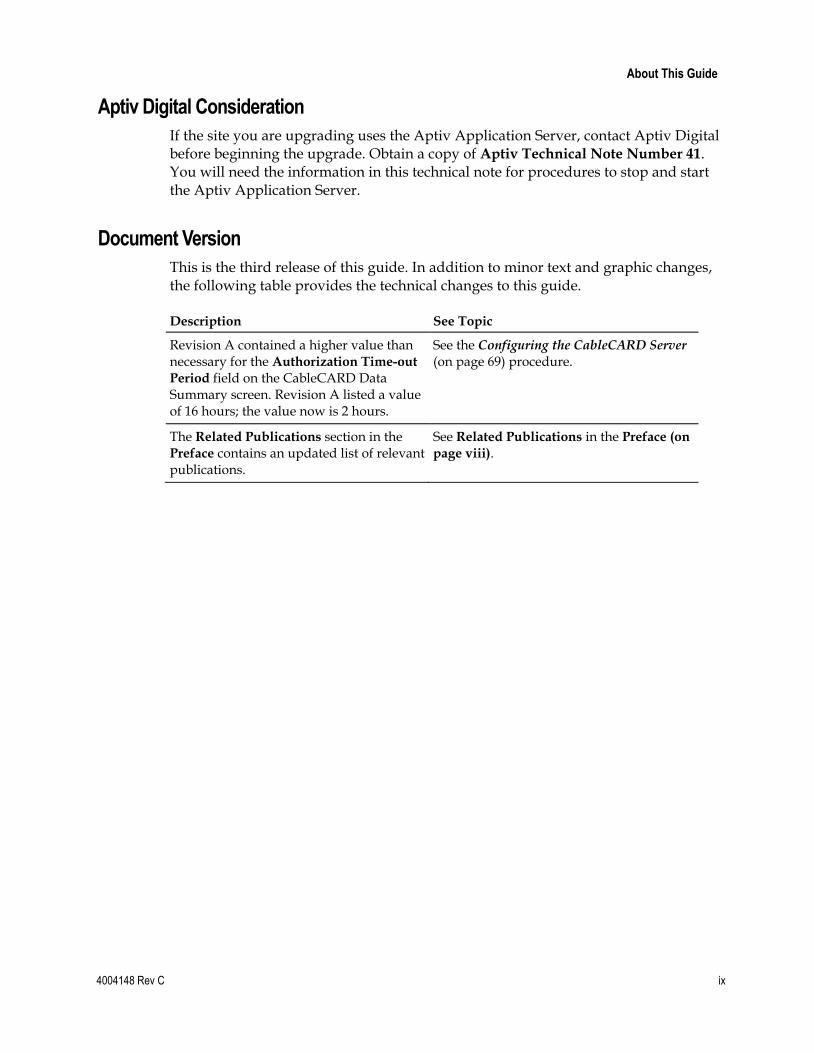
Aptiv Digital Consideration
If the site you are upgrading uses the Aptiv Application Server, contact Aptiv Digital before beginning the upgrade. Obtain a copy of Aptiv Technical Note Number 41. You will need the information in this technical note for procedures to stop and start the Aptiv Application Server.
Document Version
This is the third release of this guide. In addition to minor text and graphic changes, the following table provides the technical changes to this guide.
Description See Topic
Revision A contained a higher value than necessary for the Authorization Time-out
Period field on the CableCARD Data Summary screen. Revision A listed a value of 16 hours; the value now is 2 hours.
See the Configuring the CableCARD Server (on page 69) procedure.
The Related Publications section in the Preface contains an updated list of relevant publications.
See Related Publications in the Preface (on
page viii).

4004148 Rev C 1
Introduction
This chapter lists the major improvements and operational changes for the DBDS as a result of installing this updated service pack to the existing system release. In addition, this chapter provides important system information about this service pack.
Upgrade Path
Sites that want to upgrade to this service pack must support System Release 2.5, 3.5, or 4.0. This guide provides instructions for upgrading to SR 2.5/3.5/4.0 SP3.
Daylight Saving Time Software
The SR 2.5/3.5/4.0 SP3 software contains a Daylight Saving Time (DST) patch that loads onto the DNCS and the Application Server. This software allows the system to be configured to accommodate new rules that extend DST by 4 weeks that began with the spring 2007 time change.
Time to Complete the Upgrade
The upgrade to SR 2.5/3.5/4.0 SP3 must be completed within a maintenance window. Cisco engineers have determined that a typical site can be upgraded in approximately 6 hours.
1 Chapter 1 Introducing System Release 2.5/3.5/4.0 Service Pack 3
2 4004148 Rev C
In This Chapter
Support for Daylight Saving Time Changes ....................................... 3
Major Improvements to SR 2.5/3.5/4.0 SP3 ....................................... 4
What CRs Are Included in This Service Pack? ................................... 5
What Are the Site Requirements? ......................................................... 6
What Are the Known Issues? ................................................................ 9
Support for Daylight Saving Time Changes
4004148 Rev C 3
Support for Daylight Saving Time Changes Starting in the spring of 2007, U.S. Daylight Saving Time (DST) starts the second Sunday in March (March 11, 2007) and ends the first Sunday in November (November 4, 2007) in response to the decision by the U.S. Congress to extend DST by 4 weeks.
Cisco designed the DST Rules Feature to accommodate the new U.S. rules and to provide support for changing time on the dates that are appropriate in different parts of the world. Cisco has added parameters to system and client software to define the rules for the DST time extension.
The DNCS relies on Solaris for time keeping; therefore, the Solaris patches are critical to ensure a smooth transition to DST. To support the DST Rules Feature it is necessary to install Solaris 8 patches for Cisco products that use the Solaris 8 operating system.
To get more information on the daylight saving change, refer to the following documentation:
Preparing for the Extension of Daylight Saving Time Operations Alert
Daylight Saving Time Configuration Guide
Chapter 1 Introducing System Release 2.5/3.5/4.0 Service Pack 3
4 4004148 Rev C
Major Improvements to SR 2.5/3.5/4.0 SP3 In addition to the DST Rules feature, SR 2.5/3.5/4.0 SP3 features an operational improvement mandated by the Federal Communication Commission. After July 2007, no set-top boxes can be deployed that use embedded security. In response to this mandate, Cisco has begun producing and distributing DHCTs that require CableCARD modules for all conditional access activities. Cisco has modified the DNCS to support a method of binding the CableCARD module to the associated host set-top without user interaction or two-way staging.
What CRs Are Included in This Service Pack?
4004148 Rev C 5
What CRs Are Included in This Service Pack?
Implemented Change Requests
This list highlights some of the major improvements to the DNCS that are included in this service pack. Contact your Cisco marketing manager for additional details on any of these change requests (CRs).
CR 57524: The alarmCollector Process No Longer Leaks Memory
The alarmCollector process was modified to improve the efficiency with which system memory is used.
CR 62016: The dbUIServer Process No Longer Leaks Memory
The dbUIServer process was modified to use system memory more efficiently.
CR 62542: DSM Process on DNCS No Longer Crashes
Cisco has corrected a condition that caused an occasional crash of the DSM process on the DNCS.
Chapter 1 Introducing System Release 2.5/3.5/4.0 Service Pack 3
6 4004148 Rev C
What Are the Site Requirements?
Introduction
This section provides the following information:
Identifies the CDs that are needed to install the service pack software
List the software components tested and released as part of this service pack
Provides the antecedents and prerequisites required before installing this service pack
Antecedents
This release succeeds and carries forward all of the enhancements, features, and improvements of previous system releases and related service packs.
Prerequisites
The DBDS must meet the following prerequisites before you install this service pack:
SR 2.5, 3.5, or 4.0 is currently installed on your system.
You have the CD labeled DBDS Maintenance CD 2.1.11 (or later) in order to complete the required backups of the database and the filesystem.
Note: DBDS Maintenance CD 2.1.11 is the minimum version that is certified for SR 2.5/3.5/4.0 SP2.
Sites that are using the RNCS component of the DBDS need the DVD labeled similarly to RNCS Install DVD.
Note: Note that this is a DVD and not a CD.
DBDS Utilities Version 5.1.x or later is installed on your system.
System Release Compatibility
The following software applications and patches have been tested and are being released as part of this service pack:
DNCS Application 4.0.0.33
DNCS GUI/WUI 4.0.0.33
DNCS/Application Server Platform 3.5.0.3p2
Solaris Patches 3.5.0.3p1
What Are the Site Requirements?
4004148 Rev C 7
MQAM 2.6.2
QAM Application 2.5.1
GQAM 4.0.10
QPSK E14 / A62
This service pack can be applied to DBDS networks operating at SR 2.5, 3.5, or 4.0.
For a list of all available patches to date for SR 2.5, 3.5, or 4.0 and a complete configuration listing for SR 4.0 SP2, please contact Cisco Services.
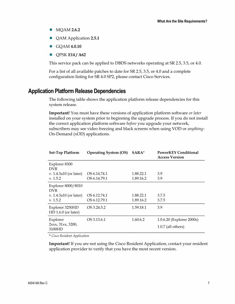
Application Platform Release Dependencies
The following table shows the application platform release dependencies for this system release.
Important! You must have these versions of application platform software or later installed on your system prior to beginning the upgrade process. If you do not install the correct application platform software before you upgrade your network, subscribers may see video freezing and black screens when using VOD or anything-On-Demand (xOD) applications.
Set-Top Platform Operating System (OS) SARA* PowerKEY Conditional Access Version
Explorer 8300 DVR v. 1.4.3a10 (or later) v. 1.5.2
OS 6.14.74.1 OS 6.14.79.1
1.88.22.1 1.89.16.2
3.9 3.9
Explorer 8000/8010 DVR v. 1.4.3a10 (or later) v. 1.5.2
OS 6.12.74.1 OS 6.12.79.1
1.88.22.1 1.89.16.2
3.7.5 3.7.5
Explorer 3250HD HD 1.6.0 (or later)
OS 3.24.5.2 1.59.18.1 3.9
Explorer 2xxx, 31xx, 3200, 3100HD
OS 3.13.6.1 1.60.6.2 1.0.6.20 (Explorer 2000s)
1.0.7 (all others)
* Cisco Resident Application
Important! If you are not using the Cisco Resident Application, contact your resident application provider to verify that you have the most recent version.
Chapter 1 Introducing System Release 2.5/3.5/4.0 Service Pack 3
8 4004148 Rev C
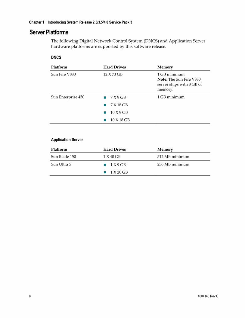
Server Platforms
The following Digital Network Control System (DNCS) and Application Server hardware platforms are supported by this software release.
DNCS
Platform Hard Drives Memory
Sun Fire V880 12 X 73 GB 1 GB minimum Note: The Sun Fire V880 server ships with 8 GB of memory.
Sun Enterprise 450 7 X 9 GB
7 X 18 GB
10 X 9 GB
10 X 18 GB
1 GB minimum
Application Server
Platform Hard Drives Memory
Sun Blade 150 1 X 40 GB 512 MB minimum
Sun Ultra 5 1 X 9 GB
1 X 20 GB
256 MB minimum
What Are the Known Issues?
4004148 Rev C 9
What Are the Known Issues? This section lists the CRs that were found while testing this software. Efforts to address these issues are ongoing in the Cisco laboratories.
CR 66001: The dbUIServer Process May Leak Memory
Cisco is aware of a condition whereby frequent use of the Session List window may exhaust system memory.
CR 66250: Batch EMM Installation for CableCARDs May Produce Multiple OUIs
Cisco engineers are aware of a condition that sometimes results in duplicate CableCARD module OUIs being written to the database during batch EMM installs.
CR 69011: Batch Installation is Required for EMMs to Pair With CableCARDs
Cisco is aware of a condition that affects some Multi-Stream CableCARD modules. When a new OUI is added to the DNCS for the first time, the EMMs must be installed using the batch install process. If the batch install process is not used, pairing of EMMs and modules in the CableCARD GUI may fail.

4004148 Rev C 11
Introduction
This chapter contains procedures that must be completed before you begin the actual upgrade process. These pre-upgrade procedures consist mainly of system checks, backups, and various operations upon the metadevices of the DNCS.
The first several procedures of this chapter can be completed before the maintenance window begins, while the actual upgrade of DNCS software must be completed during a maintenance window. See When to Complete These Procedures (on page 13) for a list of those procedures that can be completed before the start of the maintenance window.
2 Chapter 2 DNCS Pre-Upgrade Procedures
12 4004148 Rev C
In This Chapter
When to Complete These Procedures ................................................ 13
Plan Which Optional Features Will Be Supported ........................... 15
Verify the Integrity of the CDs ............................................................ 17
Verify the Integrity of the DBDS Maintenance CD .......................... 18
Check Available Disk Space ................................................................ 19
Run the Doctor Report ......................................................................... 20
Examine Mirrored Devices .................................................................. 21
Verify DBDS Stability ........................................................................... 22
Verify and Back Up the Current Modulator Software .................... 23
Check the EAS Configuration—Pre-Upgrade .................................. 24
Obtain System Configuration ............................................................. 25
Collect Network Information .............................................................. 26
Check and Remove Sessions ............................................................... 28
Back Up the DNCS and Application Server File Systems ............... 29
Stop the dhctStatus, signonCount, and cmd2000 Utilities .............. 30
Back Up and Delete the copyControlParams File ............................ 32
Back Up the Informix Database .......................................................... 33
Suspend Billing and Third-Party Interfaces ...................................... 34
Stop the cron Jobs ................................................................................. 35
Stop Cisco Basic Backup or Auto Backup Servers ........................... 37
Remove the NMI Software .................................................................. 38
Stop System Components .................................................................... 39
Ensure No Active Database Sessions on the DNCS ......................... 41
When to Complete These Procedures
4004148 Rev C 13
When to Complete These Procedures
Upgrade Process
As you are planning the upgrade, be sure to contact your billing vendor to make arrangements to suspend the billing interface on the night of the upgrade. This is an important step. Your system must not try to access the database during the upgrade process. In addition, contact the provider(s) of any third-party applications that your system supports. Follow their guidance in determining whether these third-party interfaces should be stopped and if the application needs to be updated during the upgrade.
Complete These Procedures
Pre-Maintenance Window
To save valuable time, complete the pre-maintenance window procedures in this chapter prior to the beginning of the maintenance window. Depending upon the size of the system you are upgrading, it should take about 3 or 4 hours to complete the following procedures:
Plan Which Optional Features Will Be Supported (on page 15)
Verify the Integrity of the CDs (on page 17)
Verify the Integrity of the DBDS Maintenance CD (on page 18)
Check Available Disk Space (on page 19)
Run the Doctor Report (on page 20)
Examine Mirrored Devices (on page 21)
Verify DBDS Stability (on page 22)
Verify and Back Up the Current Modulator Software (on page 23)
Check the EAS Configuration—Pre-Upgrade (on page 24)
Obtain System Configuration (on page 25)
Collect Network Information (on page 26)
Check and Remove Sessions (on page 28)
Chapter 2 DNCS Pre-Upgrade Procedures
14 4004148 Rev C
Back Up the DNCS and Application Server File Systems (on page 29)
Stop the dhctStatus, signonCount, and cmd2000 Utilities (on page 30)
Back Up and Delete the copyControlParams File (on page 32)
Back Up the Informix Database (on page 33)
During the Maintenance Window
At the beginning of the maintenance window, you should start with Suspend Billing and Third-Party Interfaces (on page 34) and complete all of the remaining procedures in Chapter 2. You should also complete the procedures in Chapter 3 during the same maintenance window.
Plan Which Optional Features Will Be Supported
4004148 Rev C 15
Plan Which Optional Features Will Be Supported
Optional Features
This software includes several optional features that system operators can elect to enable on their systems. Some of these features require that the system operator obtain a license for the feature to be activated; others can simply be activated by engineers at Cisco Services without a license.
Important! Any features that are currently enabled or licensed do not have to be re-enabled.
Determine which optional features (licensed or unlicensed) need to be enabled as a result of this upgrade. You will activate these optional features while the system processes are down.
If any licensed features are to be enabled as a result of this upgrade, contact Cisco to purchase the required license.
Licensed Features
The following licensed features can be enabled with this software:
EAS Filtering—Enables system operators to filter Emergency Alert System (EAS) messages by hub
Enhanced Interactive Session Performance—Improves the efficiency with which the DNCS processes video-on-demand (VOD) sessions
Session-Based Encryption—Activates encryption for session-based VOD
Distributed DNCS—Allows the DNCS to manage several remote headends
Chapter 2 DNCS Pre-Upgrade Procedures
16 4004148 Rev C
Enabled Features
The following list contains some of the optional features that can be enabled by engineers at Cisco Services without a special license. Not all of these features necessarily pertain to the software you are installing in this guide. Check with your North American marketing representative or Cisco Services if you are unsure about which optional features this software supports.
Conditional Access Mode—Specifies whether the Cisco (PowerKEY®) encryption method or a non-Cisco encryption method is used for DHCTs in the network
DBDS Network Overlay—Allows Cisco DHCTs to be used on a Motorola system
SI Type to Use—Specifies the type of System Information (SI) to use on the system (ATSC or DVB). ATSC is the standard SI type for North American cable systems. DVB is frequently used in Europe and other areas of the world
Dynamic PID Mapping Mode—Allows for the use of non-unique transport stream IDs (TSIDs) throughout the system
Preallocated Session Management—Permits the set up of sessions on Cisco Multiple Quadrature Amplitude modulators (MQAMs) for use by an external session resource manager process for VOD
Direct ASI—Permits the use of the Asynchronous Serial Interface (ASI) card in the DNCS for transmitting inband data directly to a QAM without the need for a Broadband Integrated Gateway (BIG)
Note: Refer to Appendix C for detailed instructions to install and configure the Direct ASI feature.
Third-Party Source—Allows tuning tables to be built for clear digital sources generated by QAMs not managed by the DNCS, and it eliminates the need to use a mirror QAM for Program and System Information Protocol (PSIP) services
Note: For additional information, refer to the technical bulletin Program and System Information Protocol Configuration for System Releases 2.5, 3.5, and 4.0.
Enhanced Split Channels—Enables two different content streams and multiple channel schedules at different times of the day
Netcrypt Bulk Encryptor—Supports encrypted digital broadcast and narrowcast transport streams across multiple headends, as well as up to three distinct conditional access systems
Verify the Integrity of the CDs
4004148 Rev C 17
Verify the Integrity of the CDs Complete the following steps for each CD, except the DBDS Maintenance CD, contained in the software binder.
Note: You will verify the DBDS Maintenance CD in a separate procedure.
1 If necessary, open an xterm window on the DNCS.
2 Complete the following steps to log on to the xterm window as root user.
a Type su - and press Enter. The password prompt appears.
b Type the root password and press Enter.
3 Insert a CD into the CD drive on the DNCS.
Note: If a File Manager window opens after you insert the CD, close the window.
4 Type cd /cdrom/cdrom0 and then press Enter. The /cdrom/cdrom0 directory becomes the working directory.
5 Type ls -la and then press Enter. The system lists the contents of the CD.
6 Did the system list the contents of the CD as expected?
If yes, go to step 7.
If no, the CD might be defective. Call Cisco Services for assistance.
7 Type pkgchk -d . SAI* and then press Enter.
Important! Be sure to type the dot between the -d and SAI*.
Results:
The system checks each package on the CD that starts with SAI.
The system performs a checksum on each package and ensures that the checksum matches what is contained on the package map.
The system lists the results of a package check.
Note: The system may list some warnings, which are normal and can be ignored. The system clearly lists any errors found during the package check.
8 Did the package check reveal any errors?
If yes, contact Cisco Services for assistance.
Important! Do not proceed with the upgrade if the CD contains errors.
If no, follow these instructions.
a Type cd / and then press Enter. b Type eject cdrom and then press Enter. c Type exit and then press Enter to log out as root user.
9 Repeat steps 2 through 8 for each CD received in the software binder.
Chapter 2 DNCS Pre-Upgrade Procedures
18 4004148 Rev C
Verify the Integrity of the DBDS Maintenance CD
Verifying the Integrity of the DBDS Maintenance CD
Complete the following steps to verify the integrity of the DBDS Maintenance CD.
1 Insert the DBDS Maintenance CD into the CD drive of the DNCS.
Note: If a File Manager window opens after you insert the CD, close the window.
2 Type cd /cdrom/cdrom0 and then press Enter. The /cdrom/cdrom0 directory becomes the working directory.
3 Type ls –l and then press Enter.
Result: The system displays the contents of the CD, which should be similar to the following example:
total 18 32060 drwxr-xr-x 8 root nobody 512 Mar 22 10:46 . 32960 drwxr-xr-x 4 root other 512 Mar 22 10:46 .. 32992 dr-xr-xr-x 2 root sys 2048 Sep 30 2005 s0 32984 drwxr-xr-x 20 root other 1024 Nov 3 09:55 s1 32983 drwxr-xr-x 2 root root 512 Jul 14 2005 s2 32982 drwxr-xr-x 5 root root 512 Nov 3 09:55 s3 32981 drwxr-xr-x 2 root root 512 Jul 14 2005 s4 32966 drwxr-xr-x 2 root root 512 Jul 14 2005 s5
4 Were the results from step 3 similar to the example?
If yes, complete the following steps.
a Type cd / and then press Enter. b Type eject cdrom and then press Enter. c Type exit and then press Enter to log out the root user.
If no, call Cisco Services.
Check Available Disk Space
4004148 Rev C 19
Check Available Disk Space Cisco recommends that you have at least 700 MB of free space on the /disk1 filesystem to install the upgrade. This procedure provides instructions to check available disk space on your DNCS.
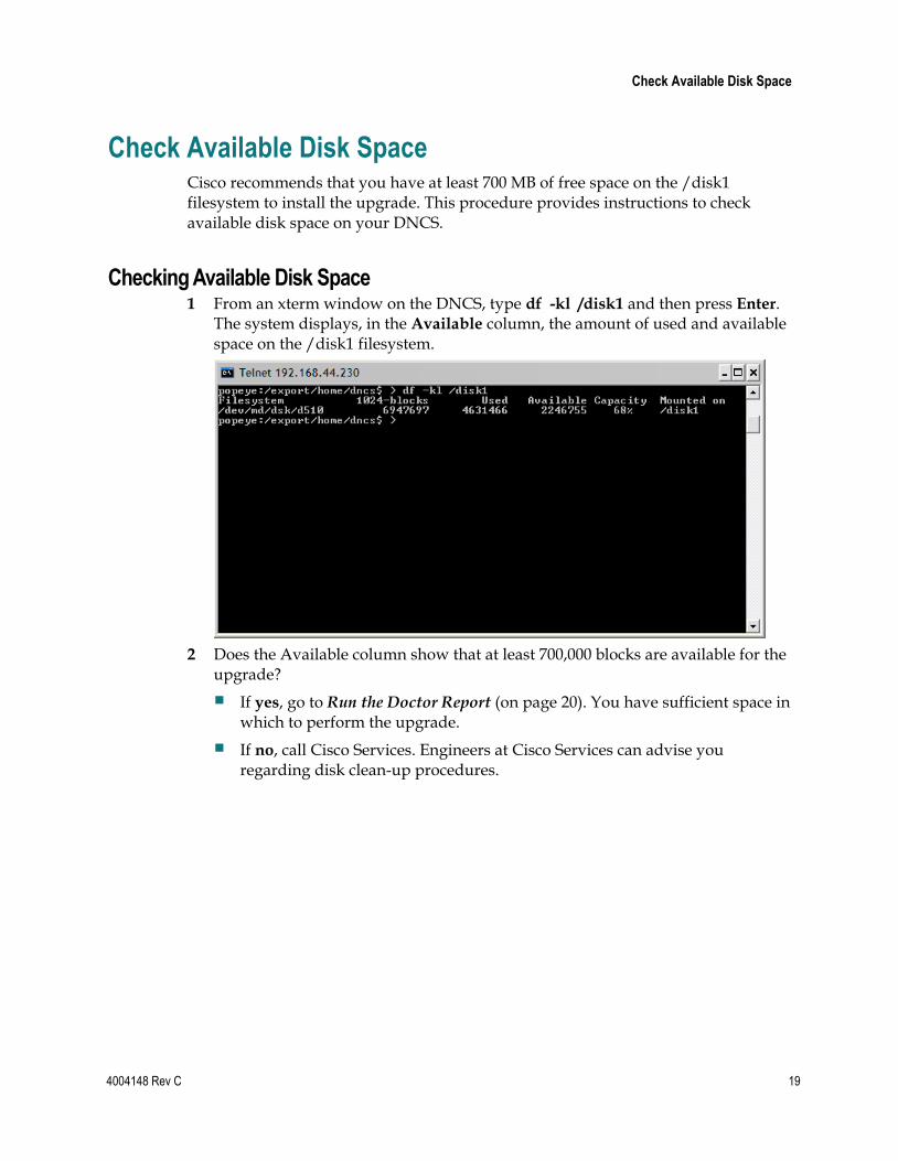
Checking Available Disk Space 1 From an xterm window on the DNCS, type df -kl /disk1 and then press Enter.
The system displays, in the Available column, the amount of used and available space on the /disk1 filesystem.
2 Does the Available column show that at least 700,000 blocks are available for the upgrade?
If yes, go to Run the Doctor Report (on page 20). You have sufficient space in which to perform the upgrade.
If no, call Cisco Services. Engineers at Cisco Services can advise you regarding disk clean-up procedures.
Chapter 2 DNCS Pre-Upgrade Procedures
20 4004148 Rev C
Run the Doctor Report
Introduction
Before upgrading the DNCS, run the Doctor report using the instructions provided in the DBDS Utilities Version 5.1 Installation Instructions and DNCS Utilities User’s Guide. The Doctor report provides key system configuration data that might be useful before you begin the upgrade process.
Notes:
On a typical system, the Doctor report takes about 10 minutes to run.
Call Cisco Services if the Doctor report indicates that the database requires additional data space or temporary space.
Analyze the Doctor Report
When you analyze the output of the Doctor report, be certain that no disk partition is at over 85 percent capacity. Call Cisco Services if the Doctor report reveals that a disk partition is over 85 percent capacity.
Also analyze the output of the Doctor report to verify that the inband SI_INSERT_RATE is not greater than 0 (zero). If the inband SI_INSERT_RATE is greater than 0 (zero), refer to Recommendations for Setting System Information to Out-of-Band, and follow the procedures provided to disable inband SI.
Note: If the inband SI is disabled, then the SI_INSERT_RATE is 0.
Important! Do not go to the next procedure until you have completed running and analyzing the Doctor report and correcting any problems it reports.
Examine Mirrored Devices
4004148 Rev C 21
Examine Mirrored Devices
Introduction
Before you disable the disk mirroring functions of the Enterprise 450 or the Sun Fire V880 DNCS in preparation of an upgrade, you should examine the status of the mirrored drives on your system. All the disk mirroring functions must be working normally before proceeding with the upgrade.
CAUTION:
If the disk mirroring functions of the DNCS are not working properly before the upgrade, you may not be able to easily recover from a failed upgrade.
Examining the Mirrored Devices
Complete the following steps to examine the status of the mirrored drives on your DNCS.
1 If necessary, open an xterm window on the DNCS.
2 Type metastat | more and then press Enter. The system displays the status of all of the metadevices on the DNCS.
Note: Press the Spacebar, if necessary, to page through all of the output.
3 Check the conditions of the following two items and then answer the question in step 4.
The designation ok appears in the State column next to each metadevice.
No Hot Spare indicates In Use.
4 Are both of the conditions listed in step 3 “true”?
If yes (to both conditions listed in step 3), go to Verify and Back Up the Current Modulator Software (on page 23).
If no (to either or both conditions listed in step 3), call Cisco Services for help in resolving these issues with the metadevices.
Chapter 2 DNCS Pre-Upgrade Procedures
22 4004148 Rev C
Verify DBDS Stability 1 Complete the following steps to perform a slow and fast boot on a test DHCT
with a working return path (2-way mode).
a Boot a DHCT.
Note: Do not press the Power button.
b Access the Power On Self Test and Boot Status diagnostic screen on the DHCT and verify that all parameters, except UNcfg, display Ready. UNcfg displays Broadcast.
Note: The fields on this screen may take up to 2 minutes to completely populate with data.
c Press the Power button on the DHCT to turn on the power and establish a two-way network connection.
d Access the Power On Self Test and Boot Status diagnostic screen on the DHCT and verify that all parameters, including UNcfg, display Ready.
2 Verify that you can ping the test DHCT.
3 Stage at least one new DHCT. After staging the DHCT, verify the following:
The DHCT loaded the current client release software.
The DHCT received at least 33 EMMs (Entitlement Management Messages).
The DHCT successfully received its Entitlement Agent.
4 Verify that the Interactive Program Guide (IPG) displays 7 days of valid and accurate data.
5 Verify the pay-per-view (PPV) barkers appear on the PPV channels correctly.
6 Verify that all third-party applications have loaded and operate properly.
7 Verify that you can purchase a video-on-demand and /or xOD program.
Verify and Back Up the Current Modulator Software
4004148 Rev C 23
Verify and Back Up the Current Modulator Software
Before beginning the upgrade process, verify the current software version of the QPSK and QAM-family of modulators. This provides the operator with an understanding of what software is currently in use on the network. At this time in the pre-upgrade process, you also need to back up this software to ensure that you can roll back to your previous network configuration.
Refer to the Verify the Current Software Version on the DNCS and Back Up the
Current Configuration Files sections in each of the following installation guides for complete instructions:
GoQAM Software Version 1.1.2 Release Notes and Installation Instructions
GQAM Software Version 4.0.10 Release Notes and Installation Instructions
MQAM Software Version 2.6.2 Release Notes and Installation Instructions
QAM Modulator Software Version 2.5.1 Release Notes and Installation Instructions
QPSK (Release E14) Release Notes and Installation Instructions
Chapter 2 DNCS Pre-Upgrade Procedures
24 4004148 Rev C
Check the EAS Configuration—Pre-Upgrade Before installing the software, verify that your EAS equipment is working correctly by testing the system’s ability to transmit EAS messages. Complete all of the procedures in the Conduct EAS Tests chapter of Configuring and Troubleshooting the Digital Emergency Alert System.
Note: You will check the EAS configuration after the upgrade to ensure there are no issues.
Obtain System Configuration
4004148 Rev C 25
Obtain System Configuration Complete the following steps to obtain basic system configuration data. You may need some of this information later during the upgrade.
1 If necessary, open an xterm window on the DNCS.
2 Type more /etc/hosts and then press Enter. A list of IP (Internet Protocol) addresses and hostnames appears.
3 On a sheet of paper, write down the IP addresses of the hosts that appear in the /etc/hosts file.
Important! At a minimum, write down the IP addresses for the following hosts:
appservatm _______________
dncsatm _______________
dncseth _______________
dncsted _______________
4 Type uname -n and then press Enter. The hostname for the DNCS appears.
Important! Call Cisco Services if the hostname contains a period (.). Cisco Services engineers will help you change it to a valid hostname.
5 Write down the hostname for the DNCS, as displayed in step 4: __________
6 From an xterm window on the Application Server, type more /etc/hosts and then press Enter. A list of IP addresses and hostnames appears.
7 Write down the IP addresses and hostnames for the following hosts:
dncsatm _______________
appservatm (if appservatm is not 10.253.0.10) _______________
8 At the Application Server, type uname -n and then press Enter. The hostname for the Application Server appears.
9 Write down the hostname for the Application Server, as displayed in step 8: _______________
Chapter 2 DNCS Pre-Upgrade Procedures
26 4004148 Rev C
Collect Network Information In this section, you are collecting network information required to reconstruct the system should the upgrade fail.
1 If necessary, open an xterm window on the DNCS.
2 Complete the following steps to log on to the xterm window as root user.
a Type su - and press Enter. The password prompt appears.
b Type the root password and press Enter.
3 Type cd /export/home/dncs and then press Enter. The /export/home/dncs directory becomes the working directory.
4 Type mkdir network and then press Enter. The system creates a directory called network.
5 Type cd network and then press Enter. The /export/home/dncs/network directory becomes the working directory.
6 Type the following commands to copy the necessary files to this newly created directory.
Important!
Press Enter after typing each command.
Note that the first few commands require a space, followed by a period, after the body of the command.
a cp -p /etc/hosts .
b cp -p /etc/hostname.* .
c cp -p /etc/netmasks .
d cp -p /etc/defaultrouter .
Note: This file may not be included in your network configuration.
e cp -p /etc/defaultdomain .
Note: This file may not be included in your network configuration.
f cp -p /etc/vfstab .
g cp -p /etc/nsswitch.conf .
h cp -p /etc/rc2.d/S82atminit .
i cp -p /etc/inet/ipnodes .
j netstat -nrv > netstat.out
k ifconfig -a > ifconfig.out
l df -k > df.out
m eeprom nvramrc > nvramrc.out
Collect Network Information
4004148 Rev C 27
7 Type cd /var/spool/cron and then press Enter.
8 Type tar cvf crontabs.< date >.tar crontabs and then press Enter.
Note: Replace < date > with the current date.
Example: tar cvf crontabs.020107.tar crontabs
9 Type cp crontabs.< date >.tar /export/home/dncs/network and then press Enter.
10 Type exit and then press Enter to log out as root user.
11 Type cd /export/home/dncs/network and then press Enter.
12 Type ls -ltr and then press Enter to verify that each file copied successfully to the /export/home/dncs/network directory and that no file has a size of 0 (zero).
Note: The "l" in ls and -ltr is a lowercase letter L.
13 Go to Check and Remove Sessions (on page 28).
Chapter 2 DNCS Pre-Upgrade Procedures
28 4004148 Rev C
Check and Remove Sessions
Introduction
After you have obtained your system configuration, your next step is to check the BFS QAM for the number of sessions and to remove any completed or orphaned sessions. This check is done both before and after the installation process is complete to provide a comparison of the number of sessions. This comparison indicates a successful upgrade by ensuring the correct number of sessions were built after the upgrade process is complete.
Checking the BFS Sessions on the BFS QAM
Complete the following steps to check and record the number of pre-upgrade BFS sessions.
1 Choose one of the following options to check the number of BFS sessions:
Press the Options button on the front panel of the BFS QAM until the Session Count total appears.
Type /dvs/dncs/bin/auditQam -query <IPAddr> 2 and press Enter.
Note: <IPAddr> is the IP address of the data QAM.
2 Record the Session Count total in the space provided. __________
Removing Completed or Orphaned Sessions
Complete the following steps to remove completed or orphaned sessions by running the clearDbSessions utility.
Note: The clearDbSessions utility takes several minutes to complete and can be running in the background as you complete the remaining procedures in this chapter.
1 If necessary, open an xterm window on the DNCS.
2 Type clearDbSessions and then press Enter. The system removes all completed session, resource, and network graph records more than 1 hour old from the database.
3 Type clearDbSessions -c and then press Enter. The system removes all completed session, resource, and network graph records from the database.
4 Type clearDbSessions -o and then press Enter. The system removes orphaned records from the database.
Back Up the DNCS and Application Server File Systems
4004148 Rev C 29
Back Up the DNCS and Application Server File Systems
Perform a complete backup of the DNCS and Cisco Application Server file system now. Procedures for backing up the file system are contained in DBDS Backup and Restore Procedures for SR 2.2 and SR 3.2, SR 2.4 and SR 3.4, SR 2.5 and SR 3.5, and SR 3.3. If necessary, call Cisco Services to obtain a copy of these backup and restore procedures.
Notes:
Procedures for backing up the file system are found in the Backing Up and
Restoring the DNCS and Application Server chapter of the DBDS Backup and Restore Procedures for SR 2.2 and SR 3.2, SR 2.4 and SR 3.4, SR 2.5 and SR 3.5, and SR 3.3.
It may take up to 2 hours to back up a DNCS file system; you can usually back up an Application Server file system in about 30 minutes.
If you have an Aptiv Application Server, refer to whatever backup procedures have been supplied to you by Aptiv Digital, and back up the file system of the Aptiv Application Server.
Chapter 2 DNCS Pre-Upgrade Procedures
30 4004148 Rev C
Stop the dhctStatus, signonCount, and cmd2000 Utilities
Introduction
When sites are being upgraded, the dhctStatus utility may occasionally be actively polling DHCTs, and the signonCount and cmd2000 utilities may be active in system memory. Upgrades proceed more smoothly when the dhctStatus utility is not actively polling DHCTs and when the signonCount and cmd2000 utilities are not in system memory. The procedures in this section guide you through the steps required to terminate the polling activity of the dhctStatus utility, as well as to remove the signonCount and cmd2000 utilities from system memory.
Terminating the dhctStatus Utility Polling Operation
Complete the following steps to determine whether the dhctStatus utility is actively polling DHCTs, and then terminate the polling operation, if necessary.
1 If necessary, open an xterm window on the DNCS.
2 Type dhctStatus and press Enter to display the dhctStatus menu.
3 To terminate the polling operation, follow these instructions.
a Type p and then press Enter. The system displays a polling menu.
b Type t and then press Enter. The system terminates the polling operation.
c Press Enter to return to the main menu.
d Press q and then press Enter to exit the menu.
4 Type ps -ef | grep dhctStatus and then press Enter to determine if all of the processes are terminated.
Example:
dncs 12514 12449 0 13:50:27 pts/3 0:00 /bin/ksh /dvs/dncs/bin/dhctStatus
dncs 12556 12514 0 13:50:28 pts/3 0:01 /usr/local/bin/perl /dvs/dncs/bin/DhctStatus/dhctStatus.pl
dncs 12681 12632 0 13:50:54 pts/10 0:00 grep dhct
5 Type kill -9 <processid> and then press Enter for any process ID displayed in step 4.
Example: kill -9 12449
Stop the dhctStatus, signonCount, and cmd2000 Utilities
4004148 Rev C 31
Removing the signonCount Utility from System Memory 1 If necessary, open an xterm window on the DNCS.
2 Type signonCount uninstall and press Enter.
Note: The utility is not permanently uninstalled; it is placed back into system memory the next time you run the signonCount utility.
3 Type ps -ef | grep signonCount and then press Enter. A list of DNCS processes and process IDs display on the screen.
4 Type kill -9 <processid> and then press Enter for each process ID displayed in step 3.
5 Type ps -ef | grep signonCount and then press Enter to ensure all the processes are terminated.
6 Repeat steps 4 and 5 for any process that continues to display active. The system should only display the grep process.
Terminating the cmd2000 Utility
Complete the following steps to determine if any cmd2000 processes are running and then to terminate them, if necessary.
1 If necessary, open an xterm window on the DNCS.
2 Type ps -ef | grep cmd2000 and press Enter. The system displays a list of cmd2000 processes.
3 Do the results from step 2 show any active cmd2000 processes?
If yes, choose one of the following options:
– If you have a Cisco Application Server, type kill -9 <processID> and then press Enter for any cmd2000 processes that may be running.
– If you have an Aptiv Application Server, type /pdt/bin/StopCmd2000Logging and then press Enter.
If no, go to Back Up and Delete the copyControlParams File (on page 32).
4 Type ps -ef | grep cmd2000 again and then press Enter to confirm that all cmd2000 processes are stopped.
5 Do the results from step 4 show that there are cmd2000 processes that are still running?
If yes, type kill -9 <processID> and then press Enter for any cmd2000 processes that may be running; then, repeat steps 4 and 5.
If no, go to Back Up and Delete the copyControlParams File (on page 32).
Chapter 2 DNCS Pre-Upgrade Procedures
32 4004148 Rev C
Back Up and Delete the copyControlParams File Complete these steps to back up and delete the copyControlParams.inf file from the DNCS.
1 If necessary, open an xterm window on the DNCS.
2 Type cd /export/home/dncs and then press Enter. The /export/home/dncs directory becomes the working directory.
3 Does the copyControlParams.inf file have any customized entries?
If yes, type cp copyControlParams.inf copyControlParams.inf.bak and then press Enter. The system makes a backup copy of the copyControlParams.inf file.
If no, go to step 4.
4 Type rm copyControlParams.inf and then press Enter. The system deletes the copyControlParams.inf file.
Note: When you restart the DNCS after the upgrade, the system will note the absence of the copyControlParams.inf file and will create a new one.
Important! After the upgrade, use the backup copy of the copyControlParams.inf file, as a reference, to add any customized entries to the new file.
Back Up the Informix Database
4004148 Rev C 33
Back Up the Informix Database Perform a complete backup of the Informix database just before the beginning of the maintenance window. This ensures that you have the latest copy of the database before the start of the upgrade. For example, if this process typically takes 45 minutes to complete, then begin this process 45 minutes before the maintenance window begins.
Procedures for backing up the database are contained in DBDS Backup and Restore Procedures for SR 2.2 and SR 3.2, SR 2.4 and SR 3.4, SR 2.5 and SR 3.5, and SR 3.3. If necessary, call Cisco Services to obtain a copy of these backup and restore procedures.
Chapter 2 DNCS Pre-Upgrade Procedures
34 4004148 Rev C
Suspend Billing and Third-Party Interfaces
Important Note About the Maintenance Window
Be sure that you are within a maintenance window as you begin this procedure. You will remain in the maintenance window as you continue to complete the installation process. The post-upgrade procedures can be completed the day after the installation is complete.
Suspending Billing and Third-Party Interfaces
Before installing this software, contact your billing vendor in order to suspend the billing interface. In addition, follow the third-party application provider's instructions you received before the maintenance window began to stop applications during the installation process.
Stop the cron Jobs
4004148 Rev C 35
Stop the cron Jobs
Introduction
Stop any cron jobs that are currently running on the DNCS and the Application Server. This ensures that no applications or programs initialize during the installation process. Follow the instructions in this section to stop all cron jobs.
Note: Take note of what time you stop the cron jobs. You may need to manually run these applications or programs after the installation is complete.
Stopping the cron Jobs on the DNCS
Complete the following steps to stop cron jobs on the DNCS.
Note: You need to be logged on to an xterm window on the DNCS as root user.
1 Type ps -ef | grep cron and then press Enter. The system lists running processes that include the word cron.
2 Did the results from step 1 include /usr/sbin/cron?
If yes, type /etc/rc2.d/S75cron stop and then press Enter. The system stops all cron jobs.
If no, go to Stopping the cron Jobs on the Cisco Application Server (on page 35); the cron jobs are already stopped on the DNCS.
3 Confirm that the cron jobs have stopped by typing ps -ef | grep cron again and then press Enter. The system should list only the grep process.
Stopping the cron Jobs on the Cisco Application Server
Follow these instructions to stop cron jobs on the Cisco Application Server.
1 Are you already logged on to an xterm window on the Application Server as root user?
If yes, go to step 2.
If no, log on to an xterm window as root user.
2 Type ps -ef | grep cron and then press Enter. The system lists running processes that include the word cron.

Chapter 2 DNCS Pre-Upgrade Procedures
36 4004148 Rev C
3 Did the results from step 2 include /usr/sbin/cron?
If yes, follow these instructions.
a Type /etc/rc2.d/S75cron stop and then press Enter. b Type ps -ef | grep cron and then press Enter to confirm that the cron jobs
have stopped. The system should list only the grep process.
If no, the cron jobs are already stopped.
Stop Cisco Basic Backup or Auto Backup Servers
4004148 Rev C 37
Stop Cisco Basic Backup or Auto Backup Servers If the site you are upgrading uses the Cisco Auto Backup or Basic Backup server and if this server is configured to start a backup during the maintenance window, disable that backup or reschedule the backup for after the maintenance window.
Chapter 2 DNCS Pre-Upgrade Procedures
38 4004148 Rev C
Remove the NMI Software 1 Are you already root user in an xterm window on the DNCS?
If yes, go to step 3.
If no, go to step 2.
2 Complete the following steps to log on to the xterm window as root user.
a Type su - and press Enter. The password prompt appears.
b Type the root password and press Enter.
3 Type pkginfo -l | grep SAInmi and then press Enter. The system lists the SAInmi package if it is installed.
4 Is SAInmi installed?
If yes, go to step 5.
If no, you do not have NMI loaded onto your system. Skip the rest of this procedure, and go to Stop System Components (on page 39).
5 Close any user interfaces that may be open on the DNCS.
Note: If the DNCS has any open user interfaces, you cannot remove the NMI software.
6 Type ps -ef | grep ui and then press Enter. The system displays a list of user interface processes that may still be running.
7 On a sheet of paper, write down the process IDs (PIDs) of any user interface process that is still running.
8 Type kill -9 [PID] and then press Enter for any user interface process that is still running. The system stops the user interface processes.
9 Type pkgrm SAInmi and then press Enter. The system deletes the NMI software.
Stop System Components
4004148 Rev C 39
Stop System Components
Introduction
Before continuing with the installation process, follow the instructions in this section to stop the Spectrum Network Management Service (Spectrum), the Application Server, and the DNCS.
Stop Third-Party Servers
Some sites use devices that mount drives on the DNCS or the Application Server. These devices are usually used to register files with the BFS or to send BOSS transactions. Be sure to stop these devices. Also, be sure to stop any third-party applications.
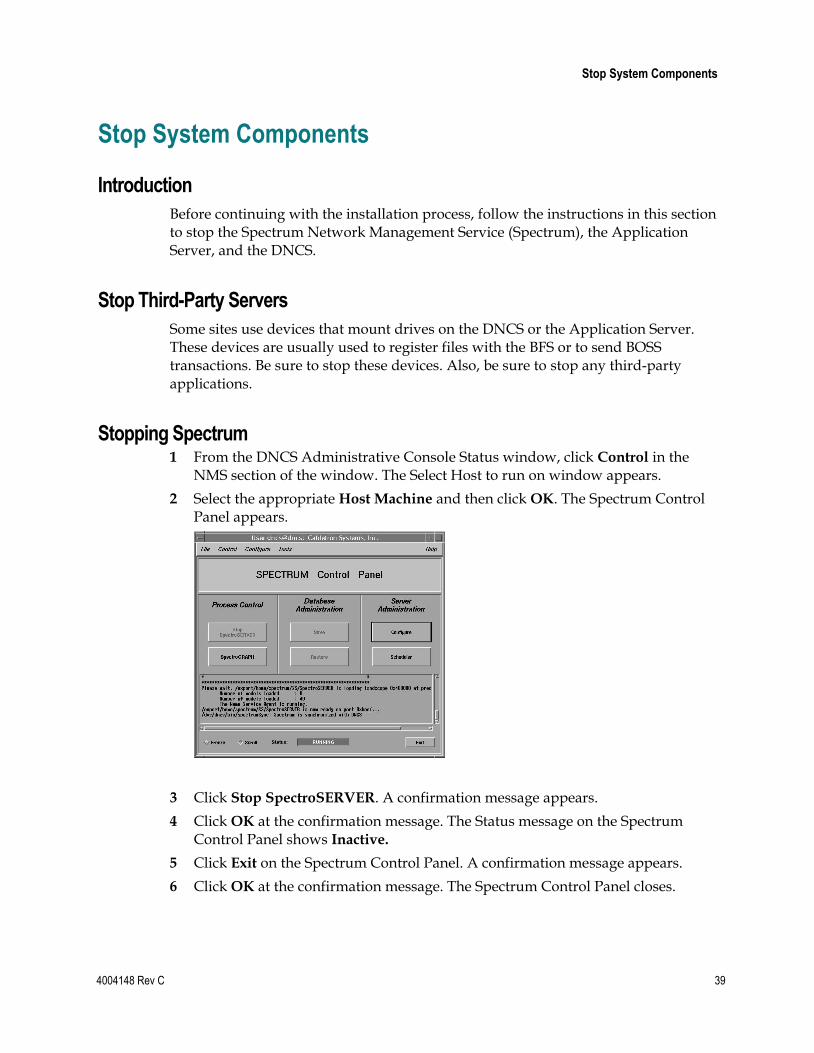
Stopping Spectrum 1 From the DNCS Administrative Console Status window, click Control in the
NMS section of the window. The Select Host to run on window appears.
2 Select the appropriate Host Machine and then click OK. The Spectrum Control Panel appears.
3 Click Stop SpectroSERVER. A confirmation message appears.
4 Click OK at the confirmation message. The Status message on the Spectrum Control Panel shows Inactive.
5 Click Exit on the Spectrum Control Panel. A confirmation message appears.
6 Click OK at the confirmation message. The Spectrum Control Panel closes.
Chapter 2 DNCS Pre-Upgrade Procedures
40 4004148 Rev C
Stopping the Application Server
This section provides procedures for stopping either a SARA Server or an Aptiv Application Server. Choose the procedure that pertains to your system.
Stopping the Application Server at SARA Sites
1 Press the middle mouse button on the Application Server and select App Serv
Stop.
2 From an xterm window on the Application Server, type appControl and then press Enter. The Applications Control window appears.
3 Type 2 (for Startup/Shutdown Single Element Group), and then press Enter. The system displays all Application Server processes.
Note: The system updates the display periodically, or you can press Enter to force an update.
4 When the Curr Stt (Current State) field of the Applications Control window indicates that all of the Application Server processes have stopped, follow the on-screen instructions to close the Applications Control window.
Preparing the Time Warner Mystro Application Server for the Service Pack
If the site you are upgrading uses the Time Warner Mystro Application Server (MDN), refer to the documents provided by Mystro to shut down the Mystro Application Server.
Preparing the Aptiv Application Server for the Service Pack
Refer to Aptiv Technical Note Number 41. Complete steps 1 through 3 to prepare the Aptiv Application Server for the service pack upgrade.
Note: Contact Aptiv Digital for the latest copy of the technical note.
Stopping the DNCS 1 At the DNCS, press the middle mouse button and then select DNCS Stop. A
confirmation message appears.
2 Click Yes.
3 From an xterm window on the DNCS, type dncsControl and then press Enter. The Dncs Control window appears.
4 Type 2 (for Startup/Shutdown Single Element Group), and then press Enter. The system displays all DNCS processes.
Note: The system updates the display periodically, or you can press Enter to force an update.
5 When the Curr Stt (Current State) field of the Dncs Control window indicates that all of the DNCS processes have stopped, follow the on-screen instructions to close the Dncs Control window.
Ensure No Active Database Sessions on the DNCS
4004148 Rev C 41
Ensure No Active Database Sessions on the DNCS 1 Close all windows and GUIs that are open except for the xterm window in which
you are working.
2 Are you already logged on as root user in the xterm window on the DNCS?
If yes, go to step 4.
If no, go to step 3.
3 Complete the following steps to log on to the xterm window as root user.
a Type su - and press Enter. The password prompt appears.
b Type the root password and press Enter.
4 Type . /dvs/dncs/bin/dncsSetup and then press Enter. The system establishes the correct user environment.
Important!
Be sure to type the dot followed by a space prior to typing /dvs.
If -0 bad options message displays, ignore the message and go to step 5.
5 Type ps -ef | grep tomcat and then press Enter. The system lists running processes that use the tomcat server.
6 Is the tomcat server running?
If yes, type /etc/rc2.d/S98tomcat stop and then press Enter.
If no, go to step 7.
7 Type ps -ef | grep tomcat and then press Enter to confirm that the tomcat server has stopped.
Note: If the tomcat server is still running, repeat step 5.
8 Type ps -ef | grep -i ui and then press Enter. The system lists running UI processes.
9 Are any UI processes running (such as dbUIServer or podUIServer)?
If yes, type /dvs/dncs/bin/stopSOAPServers and then press Enter.
If no, go to step 13.
10 Type ps -ef | grep -i ui and then press Enter to confirm that all UI processes have stopped.
Note: If any UI processes are still running, type again /dvs/dncs/bin/stopSOAPServers and then press Enter.
11 Type ps -ef | grep -i ui and then press Enter to confirm that UI process have stopped.
Chapter 2 DNCS Pre-Upgrade Procedures
42 4004148 Rev C
12 Are any UI processes still running?
If yes, type kill -9 [PID] and then press Enter for any UI process that is still running.
Note: Substitute the process ID of the running process for [PID].
If no, go to step 13.
13 Type showActiveSessions and then press Enter.
Result: One of the following messages appears:
A message indicating that the INFORMIXSERVER is idle
A message listing active database sessions
14 Did the message in step 13 indicate that there are active database sessions?
If yes, complete these steps:
a Type killActiveSessions and then press Enter. The system removes all active sessions from the database.
b Type showActiveSessions again and then press Enter. c Did a message appear indicating that there are active database sessions?
If yes, call Cisco Services.
If no, go to step 15.
If no, go to step 15.
15 Type dncsKill and then press Enter. The system terminates the dncsInitd process if it is still running.
16 Wait a few moments, and then type ps -ef | grep dncsInitd and press Enter. The system reports whether the dncsInitd process is still running.
17 If the dncsInitd process is still running, repeat this procedure from step 15.
4004148 Rev C 43
Introduction
In this chapter, you will install the new software for the DNCS and the graphical and Web user interfaces (GUI and WUI) for the DNCS.
Note: If you followed the procedures in Chapter 2 correctly, all of the system components have been stopped. Additionally, you should still be logged on to an xterm window on the DNCS as root user.
Important! Do not attempt to perform the procedures in this chapter more than once. If you encounter any problems while upgrading the DNCS, contact Cisco Services.
3 Chapter 3 System Release 2.5/3.5/4.0 SP3 Installation Procedures
In This Chapter
Detach the Disk Mirrors ....................................................................... 44
Install the Service Pack ......................................................................... 47
Install DST Patches on the Application Server ................................. 49
Install Additional Software ................................................................. 50
Check the Installed Software Version ................................................ 51
Add an EAS Variable to the .profile File ........................................... 53
Enable Optional and Licensed Features ............................................ 55
Remove Scripts That Bounce the Pass-Through Process ................ 56
Reboot the DNCS and Application Server ........................................ 58
Disable the SAM Process on Aptiv Systems ..................................... 60
Restart the System Components ......................................................... 61
Restart the Billing and Third-Party Interfaces .................................. 64
Check cron Jobs ..................................................................................... 65
Chapter 3 System Release 2.5/3.5/4.0 SP3 Installation Procedures
44 4004148 Rev C
Detach the Disk Mirrors
Introduction
In this procedure, you will detach the disk mirrors of the Enterprise E450 or Sun Fire V880 DNCS. If you fail to detach the disk mirrors, you must restore from a tape backup. Detaching the mirrors allows you the option of recovering quickly in the event of a failed upgrade by booting from the standby drives.
Important! Skip this procedure if the DNCS you are upgrading is an Enterprise 250. Disk mirroring pertains only to the Enterprise E450 or Sun Fire V880 DNCS.
Note: You should still be logged on to an xterm window on the DNCS as root user.
Detaching the Disk Mirrors
Complete the following steps to detach the disk mirrors before the upgrade to SR 2.5/3.5/4.0 SP3.
1 Insert the CD labeled DBDS Maintenance CD into the CD drive of the DNCS.
Note: If a File Manager window opens on the DNCS, close the window.
2 Type df -n and then press Enter. A list of the mounted filesystems appears.
Note: The presence of /cdrom in the output confirms that the system correctly mounted the CD.
3 Type /cdrom/cdrom0/s3/backup_restore/mirrState -d and then press Enter. The system displays the following message:
WARNING!! Proceeding beyond this point will DETACH all d7xx submirrors. Are you certain you want to proceed?
4 Type y and then press Enter. The system disables the disk mirroring functions on the DNCS.
Note: You may see a message similar to Warning: d5xx metadevice is setup as a
one way mirror. This message is normal.
Detach the Disk Mirrors
4004148 Rev C 45
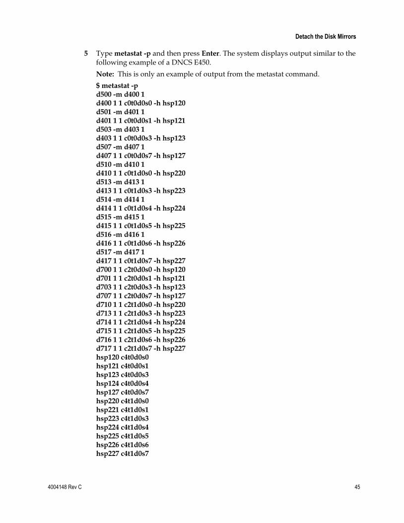
5 Type metastat -p and then press Enter. The system displays output similar to the following example of a DNCS E450.
Note: This is only an example of output from the metastat command.
$ metastat -p d500 -m d400 1 d400 1 1 c0t0d0s0 -h hsp120 d501 -m d401 1 d401 1 1 c0t0d0s1 -h hsp121 d503 -m d403 1 d403 1 1 c0t0d0s3 -h hsp123 d507 -m d407 1 d407 1 1 c0t0d0s7 -h hsp127 d510 -m d410 1 d410 1 1 c0t1d0s0 -h hsp220 d513 -m d413 1 d413 1 1 c0t1d0s3 -h hsp223 d514 -m d414 1 d414 1 1 c0t1d0s4 -h hsp224 d515 -m d415 1 d415 1 1 c0t1d0s5 -h hsp225 d516 -m d416 1 d416 1 1 c0t1d0s6 -h hsp226 d517 -m d417 1 d417 1 1 c0t1d0s7 -h hsp227 d700 1 1 c2t0d0s0 -h hsp120 d701 1 1 c2t0d0s1 -h hsp121 d703 1 1 c2t0d0s3 -h hsp123 d707 1 1 c2t0d0s7 -h hsp127 d710 1 1 c2t1d0s0 -h hsp220 d713 1 1 c2t1d0s3 -h hsp223 d714 1 1 c2t1d0s4 -h hsp224 d715 1 1 c2t1d0s5 -h hsp225 d716 1 1 c2t1d0s6 -h hsp226 d717 1 1 c2t1d0s7 -h hsp227 hsp120 c4t0d0s0 hsp121 c4t0d0s1 hsp123 c4t0d0s3 hsp124 c4t0d0s4 hsp127 c4t0d0s7 hsp220 c4t1d0s0 hsp221 c4t1d0s1 hsp223 c4t1d0s3 hsp224 c4t1d0s4 hsp225 c4t1d0s5 hsp226 c4t1d0s6 hsp227 c4t1d0s7
Chapter 3 System Release 2.5/3.5/4.0 SP3 Installation Procedures
46 4004148 Rev C
6 Verify that the d5xx metadevices contain only one submirror (d4xx).
Example: d500 -m d400 1
Note: If the d5xx metadevice contained two submirrors, the line containing the d5xx metadevice would look similar to d500 -m d400 d700 1.
7 Do the d5xx metadevices contain only one submirror?
If yes, type eject cdrom and then press Enter.
If no, repeat this procedure, or call Cisco Services for assistance.
Install the Service Pack
4004148 Rev C 47
Install the Service Pack
Two Identical Service Pack CDs
Your software binder includes two identical DBDS Service Pack CDs. These DBDS Service Pack CDs include service pack software, as well as a DST patch that needs to be installed on the DNCS and the Application Server.
To save time, Cisco recommends that you install the service pack and DST software on the DNCS and Application Server in parallel. When the software begins to install on the DNCS, you can go to Install DST Patches on the Application Server (on page 49). By installing the software on the Application Server at the same time you install the software on the DNCS, you minimize the length of time that the system components are down.
Installing the Service Pack
Note: If you have correctly followed all instructions to this point, you should still be logged on as root user in an xterm window on the DNCS.
1 Insert the DBDS Service Pack CD into the CD drive of the DNCS. The system automatically mounts the CD within 30 seconds.
2 Is the File Manager window open?
If yes, select File and choose Close, then go to step 3.
If no, go to step 3.
3 Type df -n and then press Enter. A list of the mounted file systems appears.
Note: The presence of /cdrom in the output confirms that the system correctly mounted the CD.
4 Type mv /etc/rc2.d/S75cron /etc/rc2.d/s75cron and then press Enter. The system renames the S75cron file in order to prevent the process from starting during the installation.
5 Type /cdrom/cdrom0/install_SP -i and then press Enter. A list of packages displays.
Important! Be sure to include the -i in the command.
6 Type y and then press Enter. The software begins to install on the DNCS.
Note: The system displays a message notifying the installation engineer that interactive mode is enabled.
7 Press Enter to continue. The system displays a message that asks whether you have backed up the DNCS host and the DNCS database.
Chapter 3 System Release 2.5/3.5/4.0 SP3 Installation Procedures
48 4004148 Rev C
8 Have you backed up the DNCS file systems and database?
If yes, type y and then press Enter. The system displays configuration parameters on the screen.
If no, type n and then press Enter.
Note: If you type n, the installation will terminate. Back up the file systems and database and then repeat this procedure from step 4.
9 Follow these instructions regarding the configuration parameters that are displayed on the screen.
a Examine the configuration parameters and follow onscreen instructions to change any parameter that needs to be changed.
b Type c and then press Enter when you are finished. The installation continues.
10 Type mv /etc/rc2.d/s75cron /etc/rc2.d/S75cron and then press Enter. The system renames the s75cron file back to S75cron.
11 Type eject cdrom and then press Enter when the installation is complete.
12 Check the log file for errors.
Notes:
The installation log file is in the /dvs directory of the DNCS. The name of the log file is install_SP.log.
Call Cisco Services for assistance if the log file reveals errors.
13 Choose one of the following options:
If you did not install DST software on the Application Server at the same time you installed service pack and DST software on the DNCS, go to Install DST Patches on the Application Server (on page 49).
If you chose to install the two sets of software in parallel, wait until the software finishes installing on the Application Server, and then go to Install Additional Software (on page 50).
Install DST Patches on the Application Server
4004148 Rev C 49
Install DST Patches on the Application Server In this section, you will use the DBDS Service Pack CD to install the daylight saving time (DST) patches on the Cisco Application Server.
Note: If the site you are upgrading uses the Aptiv Application Server, contact Aptiv Digital to determine whether the Aptiv Application Server needs DST patches.
Installing the DST Patches on the Application Server 1 Log onto the Application Server as root user.
2 Open an xterm window on the Application Server.
3 Complete the following steps to log on to the xterm window as root user.
a Type su - and press Enter. The password prompt appears.
b Type the root password and press Enter.
4 Insert the CD labeled DBDS Service Pack into the CD drive of the Application Server. The system automatically mounts the CD.
5 Type cd /cdrom/cdrom0/SolarisPatches and then press Enter.
6 Type ./install_patches and then press Enter. The system installs patches 109809-
03 and 108993-53.
Important! Be certain to type the period (.) before typing /install_patches.
7 Type cd / and then press Enter. The home directory on the DNCS becomes the working directory.
8 Type eject cdrom and then press Enter.
9 Type exit and then press Enter to log out as root user.
Chapter 3 System Release 2.5/3.5/4.0 SP3 Installation Procedures
50 4004148 Rev C
Install Additional Software Cisco may have provided you with additional software, such as a patch, to install after you have finished installing all of the software components. If this is the case, install the additional software now using the instructions provided with the software. These instructions may be either a written document or bundled with the software as a readme file. Either type of instructions provide step-by-step procedures to install the additional software.
After installing any additional software, go to Check the Installed Software Version (on page 51).
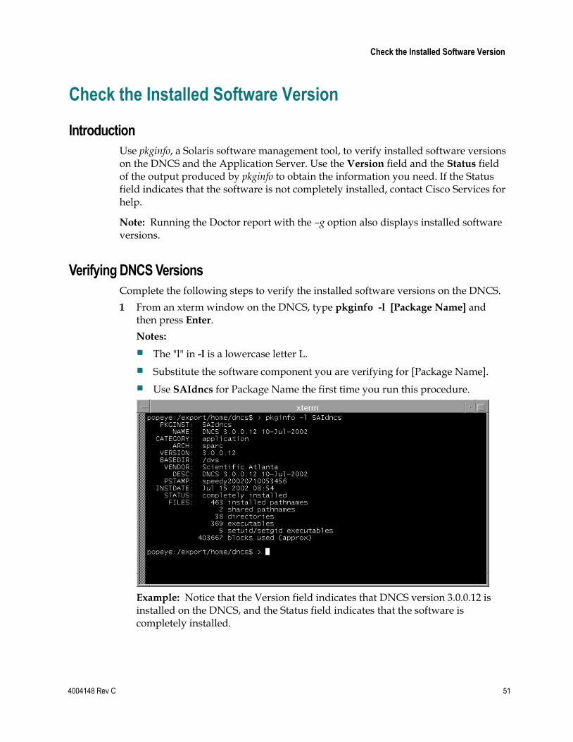
Check the Installed Software Version
4004148 Rev C 51
Check the Installed Software Version
Introduction
Use pkginfo, a Solaris software management tool, to verify installed software versions on the DNCS and the Application Server. Use the Version field and the Status field of the output produced by pkginfo to obtain the information you need. If the Status field indicates that the software is not completely installed, contact Cisco Services for help.
Note: Running the Doctor report with the –g option also displays installed software versions.
Verifying DNCS Versions
Complete the following steps to verify the installed software versions on the DNCS.
1 From an xterm window on the DNCS, type pkginfo -l [Package Name] and then press Enter.
Notes:
The "l" in -l is a lowercase letter L.
Substitute the software component you are verifying for [Package Name].
Use SAIdncs for Package Name the first time you run this procedure.
Example: Notice that the Version field indicates that DNCS version 3.0.0.12 is installed on the DNCS, and the Status field indicates that the software is completely installed.
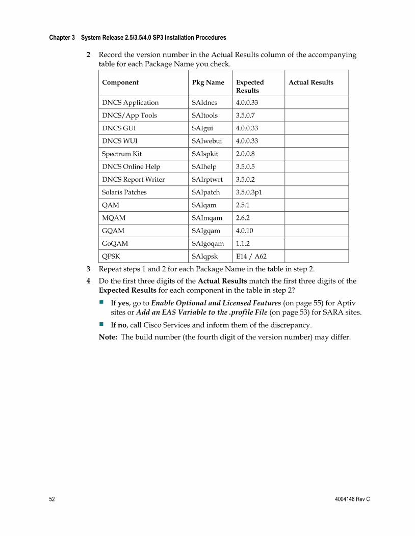
Chapter 3 System Release 2.5/3.5/4.0 SP3 Installation Procedures
52 4004148 Rev C
2 Record the version number in the Actual Results column of the accompanying table for each Package Name you check.
Component Pkg Name Expected Results
Actual Results
DNCS Application SAIdncs 4.0.0.33
DNCS/App Tools SAItools 3.5.0.7
DNCS GUI SAIgui 4.0.0.33
DNCS WUI SAIwebui 4.0.0.33
Spectrum Kit SAIspkit 2.0.0.8
DNCS Online Help SAIhelp 3.5.0.5
DNCS Report Writer SAIrptwrt 3.5.0.2
Solaris Patches SAIpatch 3.5.0.3p1
QAM SAIqam 2.5.1
MQAM SAImqam 2.6.2
GQAM SAIgqam 4.0.10
GoQAM SAIgoqam 1.1.2
QPSK SAIqpsk E14 / A62
3 Repeat steps 1 and 2 for each Package Name in the table in step 2.
4 Do the first three digits of the Actual Results match the first three digits of the Expected Results for each component in the table in step 2?
If yes, go to Enable Optional and Licensed Features (on page 55) for Aptiv sites or Add an EAS Variable to the .profile File (on page 53) for SARA sites.
If no, call Cisco Services and inform them of the discrepancy.
Note: The build number (the fourth digit of the version number) may differ.
Add an EAS Variable to the .profile File
4004148 Rev C 53
Add an EAS Variable to the .profile File
Introduction
In order to make the EAS work properly, you need to add the LOCAL_EAS_IP variable to the .profile file. This procedure describes how to add the LOCAL_EAS_IP variable.
Adding an EAS Variable to the .profile File
Complete the following steps to add the LOCAL_EAS_IP variable to the .profile file.
1 If necessary, open an xterm window on the DNCS.
2 Type grep -i LOCAL_EAS_IP /export/home/dncs/.profile and then press Enter. The system searches for LOCAL_EAS_IP in the /export/home/dncs/.profile file.
Note: Be sure to type a space between grep –i LOCAL_EAS_IP and /export/home/dncs/.profile.
3 Do the results from step 2 reveal that there is already an entry for LOCAL_EAS_IP in the /export/home/dncs/.profile?
If yes, go to Enable Optional and Licensed Features (on page 55).
If no, go to step 4.
4 Type cat /etc/hosts | grep dncseth and then press Enter. The system displays the value of the dncseth variable in the /etc/hosts file.
5 Type cat /etc/hosts | grep eac and then press Enter. The system displays the value of the eac variable in the /etc/hosts file.
6 Evaluate the results from steps 4 and 5 to determine whether the eac is on the same network as the DNCS or if it is on a different network. Refer to the following example for guidance in making this determination:
Same Network Different Network dncseth=192.168.1.2 dncseth=192.168.1.2 eac=192.168.1.5 eac=192.168.4.5
Note: When the DNCS and the eac are on the same network, the first three octets of the IP address are identical. They are on different networks when the first three octets of the IP address are different.
7 Are the DNCS and the eac on the same network?
If yes, go to step 8.
If no (they are on different networks), go to step 10.
Chapter 3 System Release 2.5/3.5/4.0 SP3 Installation Procedures
54 4004148 Rev C
8 Using a text editor, append the following line to the .profile file:
export LOCAL_EAS_IP=[Ethernet address of the DNCS]
Note: Substitute the Ethernet address of the DNCS for [Ethernet address of the DNCS], displayed in step 4. Example: LOCAL_EAS_IP=192.168.1.2
9 Go to Enable Optional and Licensed Features (on page 55).
10 Type ifconfig -a and then press Enter. Examine the output and find the IP address of the DNCS that is on the same network as the eac.
Note: In this example, the IP address of the eac (from step 6) is 192.168.4.5; the IP address of the DNCS that is on the same network as the eac is 192.168.4.1.
Example: hme0: flags=1000843< UP,BROADCAST,RUNNING,MULTICAST,IPv4 > mtu 1500 index 2 inet 192.168.1.2 netmask ffffff00 broadcast 192.168.1.255
ci0: flags=1000842< BROADCAST,RUNNING,MULTICAST,IPv4 > mtu 9180 index 5 inet 192.168.4.1 netmask ffffff00 broadcast 192.168.40.255
11 Using a text editor, append the following line to the /export/home/dncs/.profile file export LOCAL_EAS_IP=[Ethernet address of the DNCS] Note: Substitute the Ethernet address of the DNCS for [Ethernet address of the DNCS], displayed in step 10. Example: LOCAL_EAS_IP=192.168.4.1
12 Go to Enable Optional and Licensed Features (on page 55).
Enable Optional and Licensed Features
4004148 Rev C 55
Enable Optional and Licensed Features
Enabling Optional and Licensed Features
If you have properly followed the instructions in this chapter, the system processes should currently be stopped. Now is the time to enable the optional features you have chosen as part of this upgrade, except for Direct ASI. Contact Cisco Services to have the licensed or optional features enabled on your network.
Exception: The Direct ASI feature requires extensive system configuration. If the system you are upgrading is to support this feature, go to Direct ASI Installation and Configuration Procedures (on page 99) for instructions to install and configure this feature.
Chapter 3 System Release 2.5/3.5/4.0 SP3 Installation Procedures
56 4004148 Rev C
Remove Scripts That Bounce the Pass-Through Process
Introduction
In order to correct some issues associated with the Pass-Through process on the DNCS, some sites have been regularly bouncing this process through scripts that reside in the crontab file. This software corrects issues associated with the Pass-Through process. Therefore, after the upgrade, you should remove any entries in the crontab file that reference scripts that bounce the Pass-Through process. The instructions in this section guide you through the process of removing these references.
Notes:
Bouncing a process refers to stopping and then restarting that process.
The scripts that Cisco wrote to bounce the Pass-Through process are called elop.sh and bouncePassThru.
Removing Scripts That Bounce the Pass-Through Process
Complete the following steps to remove entries from the crontab file that reference scripts that bounce the Pass-Through process.
1 If necessary, open an xterm window on the DNCS.
2 Follow these instructions to check on the presence of scripts in the crontab file that bounce the Pass-Through process.
a Type crontab -l | grep -i elop.sh and then press Enter. The system lists the line(s) within the crontab file that contain elop.ksh.
b Type crontab -l | grep -i bouncePassThru and then press Enter. The system lists the line(s) within the crontab file that contain bouncePassThru.
3 Did the output of step 2 contain any references to the elop.sh or the bouncePassThru scripts?
If yes, go to step 4 to remove those references.
If no, go to Reboot the DNCS and Application Server (on page 58).
Note: You do not have to remove any references to the scripts from the crontab file.

Remove Scripts That Bounce the Pass-Through Process
4004148 Rev C 57
4 Type crontab -l > /tmp/dncs.crontab and then press Enter. The system redirects the contents of the crontab into dncs.crontab.
Note: While you can edit the crontab directly, Cisco recommends that you first redirect the contents of the crontab to dncs.crontab so you can recover the original crontab if necessary.
5 Type vi /tmp/dncs.crontab and then press Enter. The dncs.crontab file opens for editing using the vi text editor.
6 Remove all lines from the dncs.crontab file that reference the elop.ksh or bouncePassThru scripts.
7 Save the dncs.crontab file and close the vi text editor.
8 Type crontab /tmp/dncs.crontab and then press Enter. The just-edited dncs.crontab file becomes the crontab file.
Chapter 3 System Release 2.5/3.5/4.0 SP3 Installation Procedures
58 4004148 Rev C
Reboot the DNCS and Application Server After installing the software onto the DNCS, complete the following steps to reboot the DNCS and Application Server.
1 Choose one of the following options:
If you are using a Cisco Application Server, open an xterm window (if necessary) on the Application Server.
If you are using an Aptiv Application Server, skip to step 4.
2 Complete the following steps to log on to the xterm window as root user.
a Type su - and press Enter. The password prompt appears.
b Type the root password and press Enter.
3 From the xterm window on the Application Server, type /usr/sbin/shutdown -g0 -y -i0 and then press Enter. The Application Server shuts down.
4 If necessary, open an xterm window on the DNCS.
5 Complete the following steps to log on to the xterm window as root user.
a Type su - and press Enter. The password prompt appears.
b Type the root password and press Enter.
6 From the xterm window on the DNCS, type /usr/sbin/shutdown -g0 -y -i6 and then press Enter. The DNCS reboots and the CDE Login window appears.
7 Log on to the DNCS as dncs user.
8 Choose one of the following options:
If the site you are upgrading uses the Cisco Application Server, go to step 9.
If the site you are upgrading uses the Aptiv application server, go to step 11.
9 At the ok prompt on the Cisco Application Server, type boot and then press Enter. The Application Server reboots.
10 Log on to the Application Server as dncs user.
11 Choose one of the following options:
If you are using a Cisco Application Server, go to Restart the System Components (on page 61).
If you are using an Aptiv Application Server, go to Disable the SAM Process on Aptiv Systems (on page 60). Then return here and resume with step 12.

Reboot the DNCS and Application Server
4004148 Rev C 59
12 Go to Restart the System Components (on page 61) and follow the procedures to restart Spectrum and the DNCS. Then return here and resume with step 13.
13 Refer to Aptiv Technical Note Number 41 and complete steps 6 through 14. Then, return here and resume with step 14.
14 Go to Restart the Billing and Third-Party Interfaces (on page 64).
Chapter 3 System Release 2.5/3.5/4.0 SP3 Installation Procedures
60 4004148 Rev C
Disable the SAM Process on Aptiv Systems If the site you are upgrading uses the Aptiv application server, you need to disable the SAM process before you restart the system components. Complete the following steps to disable the SAM process.
Notes:
If the site you are upgrading does not use the Aptiv application server, skip this procedure and go to Restart the System Components (on page 61).
You should be logged on to the DNCS as dncs user.
1 In the DNCS section of the DNCS Administrative Console Status window, click Control. The DNCS Monitor window opens.
2 From an xterm window on the DNCS, type dncsControl and then press Enter. The DNCS Control window opens.
3 Type 4 (for Define/Update Grouped Elements) and then press Enter. The window updates to list a series of element groups.
4 Type 14 (for saManager) and then press Enter. The window updates to list the elements in the group.
5 Type 1 (for /dvs/dncs/bin/saManager) and then press Enter. The first in a series of confirmation messages appears.
6 Press Enter at each conformation message to accept the default setting until a message about cpElmtExecCtrlStatus appears. In total, you should see about six confirmation messages.
7 At the cpElmtExecCtrlStatus message, type 2 (for Disabled) and then press Enter. A confirmation message appears.
8 Type y (for yes) and then press Enter. The message Element Definition was
Modified appears.
9 Follow the on-screen instructions to exit from the DNCS Control window.
10 Return to Reboot the DNCS and Application Server (on page 58) and resume with step 12.
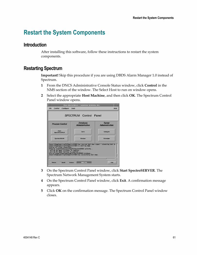
Restart the System Components
4004148 Rev C 61
Restart the System Components
Introduction
After installing this software, follow these instructions to restart the system components.
Restarting Spectrum
Important! Skip this procedure if you are using DBDS Alarm Manager 1.0 instead of Spectrum.
1 From the DNCS Administrative Console Status window, click Control in the NMS section of the window. The Select Host to run on window opens.
2 Select the appropriate Host Machine, and then click OK. The Spectrum Control Panel window opens.
3 On the Spectrum Control Panel window, click Start SpectroSERVER. The Spectrum Network Management System starts.
4 On the Spectrum Control Panel window, click Exit. A confirmation message appears.
5 Click OK on the confirmation message. The Spectrum Control Panel window closes.
Chapter 3 System Release 2.5/3.5/4.0 SP3 Installation Procedures
62 4004148 Rev C
Restarting the DNCS 1 Click the middle mouse button on the DNCS and select DNCS Start. The DNCS
processes start.
2 Click the middle mouse button on the DNCS and select Administrative Console. The DNCS Administrative Console opens.
3 From the DNCS Administrative Console Status window, click DNCS Control.
Results:
The DNCS Control window opens.
Green indicators begin to replace red indicators on the DNCS Control window.
4 From an xterm window on the DNCS, type dncsControl and then press Enter. The Dncs Control utility window opens.
5 Type 2 (for Startup / Shutdown Single Element Group) and then press Enter. The Dncs Control window updates to list the status of all of the processes and servers running on the DNCS.
6 Wait for the Dncs Control window to list the current status (Curr Stt) of all the processes and servers as running.
Notes:
The Dncs Control window updates automatically every few seconds or you can press Enter to force an update.
The indicators on the DNCS Control window all become green when the processes and servers have restarted.
Restarting the Application Server
This section provides procedures for restarting either a SARA Server or an Aptiv Application Server. Choose the procedure that pertains to your system.
Restarting the Application Server at SARA Sites
1 Press the middle mouse button on the Application Server and select App Serv
Start.
2 From an xterm window on the Application Server, type appControl and then press Enter. The Applications Control window opens.
3 Select option 2 on the Applications Control window. The system displays a list of Application Server processes and their current status.
Note: The system updates the display periodically, or you can press Enter to force an update.
4 When the Application Control window indicates that the current state (Curr Stt) of each process is stopped, follow the on-screen instructions to close the Applications Control window.
Restart the System Components
4004148 Rev C 63
Preparing the Aptiv Application Server for the Service Pack
Refer to Aptiv Technical Note Number 41. Complete steps 6 through 14 to restart the Aptiv Application Server after the upgrade is complete.
Note: Contact Aptiv Digital for the latest copy of the technical note.
Restarting the Time Warner Mystro Application Server
If necessary, refer to the documents supplied by Mystro to restart the MDN.
Chapter 3 System Release 2.5/3.5/4.0 SP3 Installation Procedures
64 4004148 Rev C
Restart the Billing and Third-Party Interfaces Contact your billing vendor to restart the billing interface. If you stopped any third-party interfaces during the pre-upgrade process, restart those interfaces now. Additionally, examine the dncs and root crontab files for any third-party interfaces that were scheduled to start during the installation process while the system components were stopped. Restart these interfaces, as well.
Restarting the Time Warner Mystro Application Server
If necessary, refer to the documents supplied by Mystro to restart the MDN.

Check cron Jobs
4004148 Rev C 65
Check cron Jobs After restarting the billing and third-party interfaces, examine the root and dncs crontab entries for any cron jobs that may not have run, such as the IPG Collector, during the maintenance window while cron jobs were stopped. If necessary, run these cron jobs manually.

4004148 Rev C 67
Introduction
Follow the procedures in this chapter to complete the upgrade process.
4 Chapter 4 Post-Upgrade Procedures
In This Chapter
Configure SAM Timers ........................................................................ 68
Configure the CableCARD Server ...................................................... 69
Check the EAS Configuration—Post Upgrade ................................. 71
Check BFS QAM Sessions .................................................................... 72
Authorize the BRF as a BFS Server (Optional) ................................. 75
System Validation Tests (Before Modulator Reset) ......................... 78
Reset the Modulators............................................................................ 80
Final System Validation Tests ............................................................. 81
Reinstall the NMI Software ................................................................. 83
Reattach the Disk Mirrors .................................................................... 84
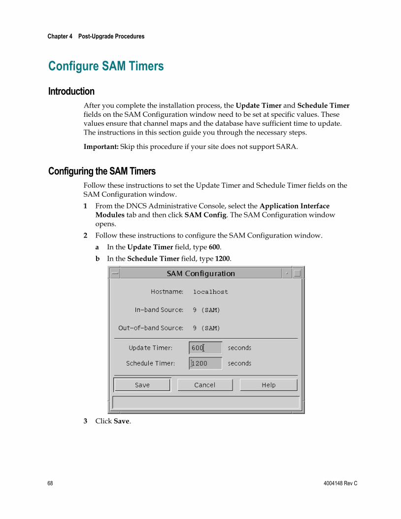
Chapter 4 Post-Upgrade Procedures
68 4004148 Rev C
Configure SAM Timers
Introduction
After you complete the installation process, the Update Timer and Schedule Timer fields on the SAM Configuration window need to be set at specific values. These values ensure that channel maps and the database have sufficient time to update. The instructions in this section guide you through the necessary steps.
Important: Skip this procedure if your site does not support SARA.
Configuring the SAM Timers
Follow these instructions to set the Update Timer and Schedule Timer fields on the SAM Configuration window.
1 From the DNCS Administrative Console, select the Application Interface
Modules tab and then click SAM Config. The SAM Configuration window opens.
2 Follow these instructions to configure the SAM Configuration window.
a In the Update Timer field, type 600.
b In the Schedule Timer field, type 1200.
3 Click Save.
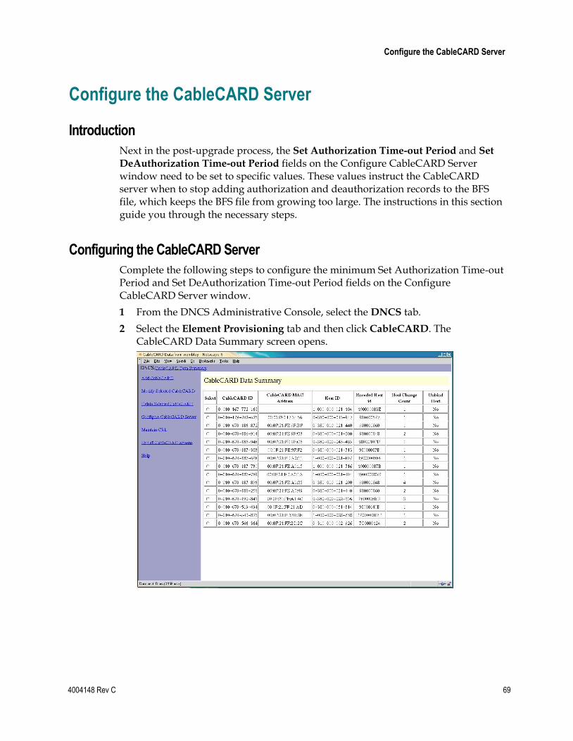
Configure the CableCARD Server
4004148 Rev C 69
Configure the CableCARD Server
Introduction
Next in the post-upgrade process, the Set Authorization Time-out Period and Set
DeAuthorization Time-out Period fields on the Configure CableCARD Server window need to be set to specific values. These values instruct the CableCARD server when to stop adding authorization and deauthorization records to the BFS file, which keeps the BFS file from growing too large. The instructions in this section guide you through the necessary steps.
Configuring the CableCARD Server
Complete the following steps to configure the minimum Set Authorization Time-out Period and Set DeAuthorization Time-out Period fields on the Configure CableCARD Server window.
1 From the DNCS Administrative Console, select the DNCS tab.
2 Select the Element Provisioning tab and then click CableCARD. The CableCARD Data Summary screen opens.
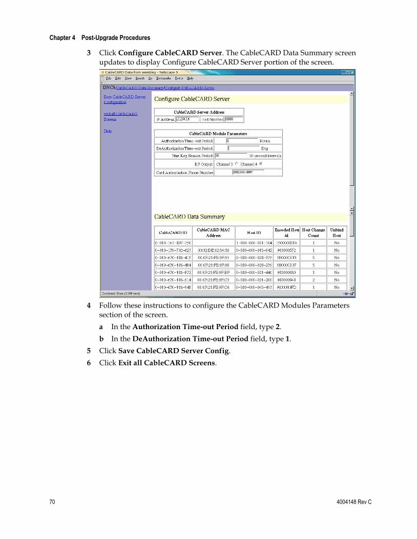
Chapter 4 Post-Upgrade Procedures
70 4004148 Rev C
3 Click Configure CableCARD Server. The CableCARD Data Summary screen updates to display Configure CableCARD Server portion of the screen.
4 Follow these instructions to configure the CableCARD Modules Parameters section of the screen.
a In the Authorization Time-out Period field, type 2.
b In the DeAuthorization Time-out Period field, type 1.
5 Click Save CableCARD Server Config.
6 Click Exit all CableCARD Screens.
Check the EAS Configuration—Post Upgrade
4004148 Rev C 71
Check the EAS Configuration—Post Upgrade You now need to verify that your EAS equipment is working correctly by testing the system’s ability to transmit EAS messages. Complete all of the procedures in the Conduct EAS Tests chapter of Configuring and Troubleshooting the Digital Emergency Alert System. After completing the procedures in that chapter, verify an EAS message is generated from the Emergency Alert Controller (EAC).
Chapter 4 Post-Upgrade Procedures
72 4004148 Rev C
Check BFS QAM Sessions
Introduction
After you have obtained your system configuration, your next step is to check the BFS QAM for the number of sessions and to remove any completed or orphaned sessions. This check is done both before and after the installation process is complete to provide a comparison of the number of sessions. This comparison indicates a successful upgrade by ensuring the correct number of sessions were built after the upgrade process is complete.
Verifying the Number of Recovered BFS Sessions
Complete the following steps to check the number of post-upgrade BFS sessions.
1 Choose one of the following options to check the number of BFS sessions:
Press the Options button on the front panel of the BFS QAM until the Session Count total appears.
Type /dvs/dncs/bin/auditQam -query <IPAddr> 2 and press Enter.
Note: <IPAddr> is the IP address of the data QAM.
2 Does the Session Count total equal the number of sessions you recorded in the Checking the BFS Sessions on the BFS QAM (on page 28) procedure?
If yes, skip the remainder of this section, and go to Authorize the BRF as a BFS Server (Optional) (on page 75). The system recovered all of the BFS sessions.
If no, go to Tear Down BFS and OSM Sessions.
Tear Down BFS and OSM Sessions
Complete the following steps to tear down the BFS and OSM sessions in order to return the BFS session count to the expected number of sessions.
1 On the DNCS Control window, highlight the osm process.
2 Click Process and then select Stop Process. In a few minutes, the indicator for the osm process changes from green to red.
3 Highlight the bfsServer process.
4 Click Process and then select Stop Process. In a few minutes, the indicator for the bfsServer process changes from green to red.
5 On the DNCS Administrative Console, select the DNCS tab and go to Utilities.
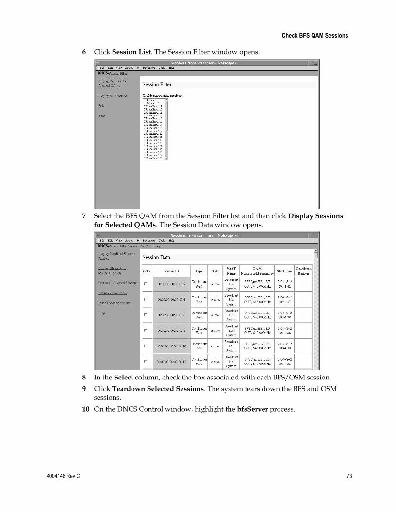
Check BFS QAM Sessions
4004148 Rev C 73
6 Click Session List. The Session Filter window opens.
7 Select the BFS QAM from the Session Filter list and then click Display Sessions
for Selected QAMs. The Session Data window opens.
8 In the Select column, check the box associated with each BFS/OSM session.
9 Click Teardown Selected Sessions. The system tears down the BFS and OSM sessions.
10 On the DNCS Control window, highlight the bfsServer process.
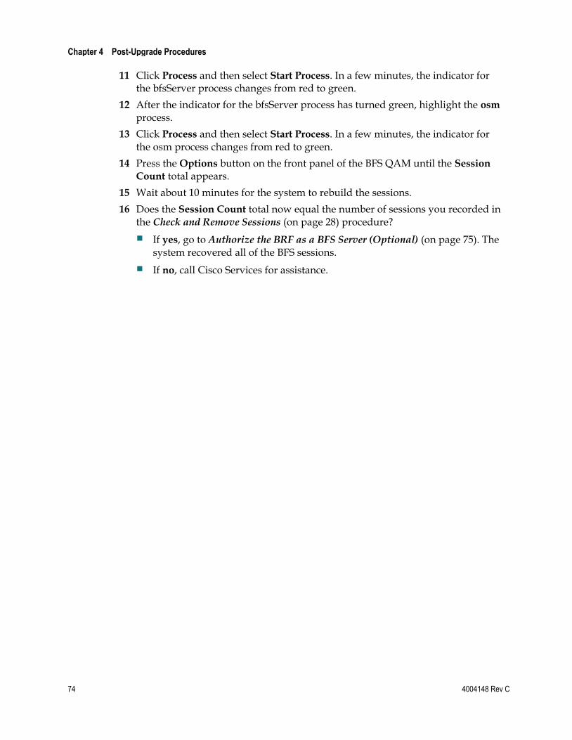
Chapter 4 Post-Upgrade Procedures
74 4004148 Rev C
11 Click Process and then select Start Process. In a few minutes, the indicator for the bfsServer process changes from red to green.
12 After the indicator for the bfsServer process has turned green, highlight the osm process.
13 Click Process and then select Start Process. In a few minutes, the indicator for the osm process changes from red to green.
14 Press the Options button on the front panel of the BFS QAM until the Session
Count total appears.
15 Wait about 10 minutes for the system to rebuild the sessions.
16 Does the Session Count total now equal the number of sessions you recorded in the Check and Remove Sessions (on page 28) procedure?
If yes, go to Authorize the BRF as a BFS Server (Optional) (on page 75). The system recovered all of the BFS sessions.
If no, call Cisco Services for assistance.
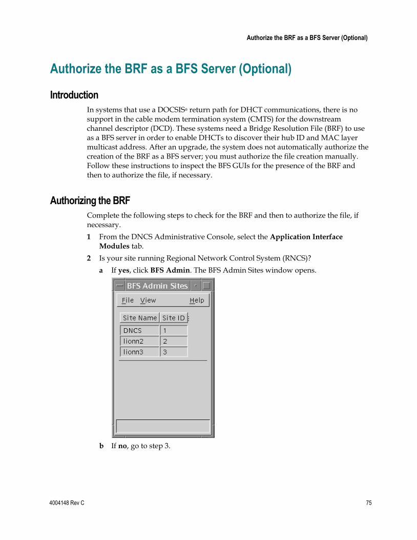
Authorize the BRF as a BFS Server (Optional)
4004148 Rev C 75
Authorize the BRF as a BFS Server (Optional)
Introduction
In systems that use a DOCSIS® return path for DHCT communications, there is no support in the cable modem termination system (CMTS) for the downstream channel descriptor (DCD). These systems need a Bridge Resolution File (BRF) to use as a BFS server in order to enable DHCTs to discover their hub ID and MAC layer multicast address. After an upgrade, the system does not automatically authorize the creation of the BRF as a BFS server; you must authorize the file creation manually. Follow these instructions to inspect the BFS GUIs for the presence of the BRF and then to authorize the file, if necessary.
Authorizing the BRF
Complete the following steps to check for the BRF and then to authorize the file, if necessary.
1 From the DNCS Administrative Console, select the Application Interface
Modules tab.
2 Is your site running Regional Network Control System (RNCS)?
a If yes, click BFS Admin. The BFS Admin Sites window opens.
b If no, go to step 3.
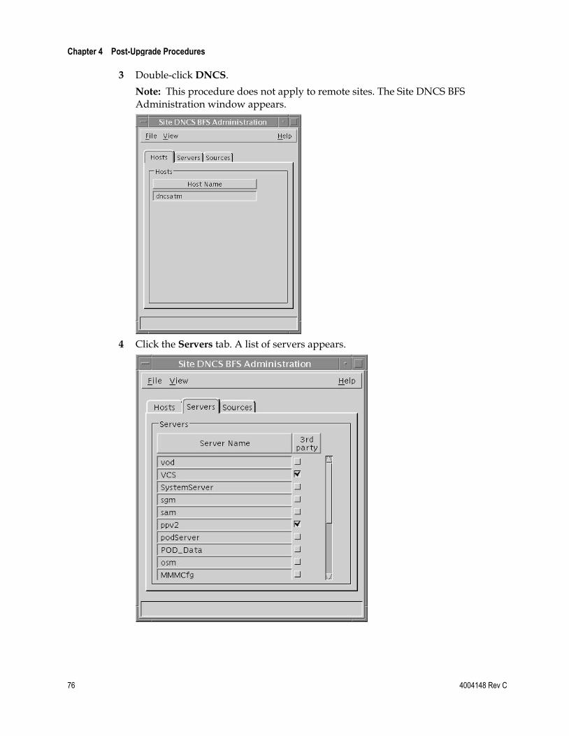
Chapter 4 Post-Upgrade Procedures
76 4004148 Rev C
3 Double-click DNCS.
Note: This procedure does not apply to remote sites. The Site DNCS BFS Administration window appears.
4 Click the Servers tab. A list of servers appears.
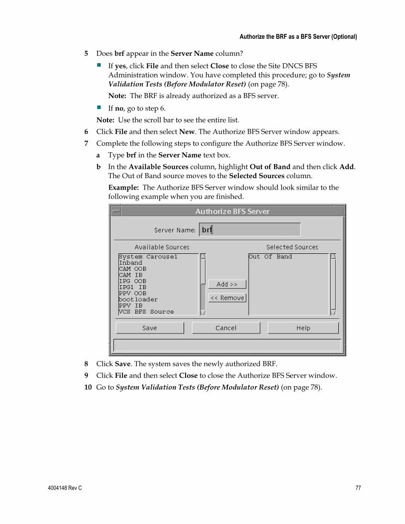
Authorize the BRF as a BFS Server (Optional)
4004148 Rev C 77
5 Does brf appear in the Server Name column?
If yes, click File and then select Close to close the Site DNCS BFS Administration window. You have completed this procedure; go to System Validation Tests (Before Modulator Reset) (on page 78).
Note: The BRF is already authorized as a BFS server.
If no, go to step 6.
Note: Use the scroll bar to see the entire list.
6 Click File and then select New. The Authorize BFS Server window appears.
7 Complete the following steps to configure the Authorize BFS Server window.
a Type brf in the Server Name text box.
b In the Available Sources column, highlight Out of Band and then click Add. The Out of Band source moves to the Selected Sources column.
Example: The Authorize BFS Server window should look similar to the following example when you are finished.
8 Click Save. The system saves the newly authorized BRF.
9 Click File and then select Close to close the Authorize BFS Server window.
10 Go to System Validation Tests (Before Modulator Reset) (on page 78).
Chapter 4 Post-Upgrade Procedures
78 4004148 Rev C
System Validation Tests (Before Modulator Reset)
Verifying a Successful Installation 1 Complete the following steps to perform a slow boot and a fast boot on a DHCT
with a working return path (2-way mode).
a Boot a DHCT.
Note: Do not press the Power button.
b Access the Power On Self Test and Boot Status diagnostic screen on the DHCT and verify that all parameters, except UNcfg, display Ready.
Note: UNcfg displays Broadcast.
c Wait 5 minutes.
d Press the power button on the DHCT. Power to the DHCT is turned on.
e Access the Power On Self Test and Boot Status diagnostic screen on the DHCT.
f Do all of the parameters, including UNcfg, display Ready?
– If yes, go to step 2.
– If no, contact Cisco Services.
2 Ping a test DHCT.
3 Did the DHCT receive the ping?
If yes, go to step 4.
If no, call Cisco Services.
4 Stage at least one new DHCT to the system operator’s specifications.
5 After staging, did the DHCT successfully load the current client release software?
If yes, go to step 6.
If no, call Cisco Services for assistance.
6 Did the DHCT receive at least 33 EMMs (Entitlement Management Messages) and successfully receive its Entitlement Agent?
If yes, go to step 7.
If no, call Cisco Services for assistance.
7 Does the IPG display 7 days of valid and accurate data?
If yes, go to step 8.
If no, call Cisco Services for assistance.
System Validation Tests (Before Modulator Reset)
4004148 Rev C 79
8 Do the PPV barkers appear on the PPV channels correctly?
If yes, go to step 9.
If no, call Cisco Services for assistance.
9 Do third-party applications load and run properly?
If yes, go to step 10.
If no, call Cisco Services for assistance.
10 Can test DHCTs buy a VOD and/or an xOD program?
If yes, go to step 11.
If no, call Cisco Services for assistance.
11 Boot a DHCT and look at Statuses and Network Parameter Diagnostic Screen. Is the Hub ID number displayed?
If yes, the BRF is successfully authorized and you have completed the upgrade.
If no, call Cisco Services for assistance.
Chapter 4 Post-Upgrade Procedures
80 4004148 Rev C
Reset the Modulators After completing the upgrade process, it is now time to reset the modulators in your network. Go to the Establish a Download Sequence and Download Software to the
Modulators sections in the following installation guides:
GoQAM Software Version 1.1.2 Release Notes and Installation Instructions
GQAM Software Version 4.0.10 Release Notes and Installation Instructions
MQAM Software Version 2.6.2 Release Notes and Installation Instructions
QAM Modulator Software Version 2.5.1 Release Notes and Installation Instructions
For QPSK modulators, go to the Download Software to the QPSK Modulators and Continue to Monitor the DHCT Sign-On Traffic sections in the QPSK (Release E14) Release Notes and Installation Instructions.
Final System Validation Tests
4004148 Rev C 81
Final System Validation Tests
Verifying a Successful Installation 1 Complete the following steps to perform a slow boot and a fast boot on a DHCT
with a working return path (2-way mode).
a Boot a DHCT.
Note: Do not press the Power button.
b Access the Power On Self Test and Boot Status diagnostic screen on the DHCT and verify that all parameters, except UNcfg, display Ready.
Note: UNcfg displays Broadcast.
c Wait 5 minutes.
d Press the power button on the DHCT. Power to the DHCT is turned on.
e Access the Power On Self Test and Boot Status diagnostic screen on the DHCT.
f Do all of the parameters, including UNcfg, display Ready?
– If yes, go to step 2.
– If no, contact Cisco Services.
2 Ping a test DHCT.
3 Did the DHCT receive the ping?
If yes, go to step 4.
If no, call Cisco Services.
4 Stage at least one new DHCT to the system operator’s specifications.
5 After staging, did the DHCT successfully load the current client release software?
If yes, go to step 6.
If no, call Cisco Services for assistance.
6 Did the DHCT receive at least 33 EMMs (Entitlement Management Messages) and successfully receive its Entitlement Agent?
If yes, go to step 7.
If no, call Cisco Services for assistance.
7 Does the IPG display 7 days of valid and accurate data?
If yes, go to step 8.
If no, call Cisco Services for assistance.
Chapter 4 Post-Upgrade Procedures
82 4004148 Rev C
8 Do the PPV barkers appear on the PPV channels correctly?
If yes, go to step 9.
If no, call Cisco Services for assistance.
9 Do third-party applications load and run properly?
If yes, go to step 10.
If no, call Cisco Services for assistance.
10 Can test DHCTs buy a VOD and/or an xOD program?
If yes, go to step 11.
If no, call Cisco Services for assistance.
11 Boot a DHCT and look at Statuses and Network Parameter Diagnostic Screen. Is the Hub ID number displayed?
If yes, the BRF is successfully authorized and you have completed the upgrade.
If no, call Cisco Services for assistance.

Reinstall the NMI Software
4004148 Rev C 83
Reinstall the NMI Software
Reinstalling the NMI Software
If you removed the NMI software as part of this upgrade, you need to reinstall the NMI software now. Complete the following steps to reinstall the NMI software.
1 If necessary, open an xterm window on the DNCS.
2 Complete the following steps to log on to the xterm window as root user.
a Type su - and press Enter. The password prompt appears.
b Type the root password and press Enter.
3 Type pkginfo -l | grep SAInmi and then press Enter. The system lists the SAInmi package if it is installed.
4 Is SAInmi installed?
If yes, go to step 5.
If no, you do not have NMI loaded onto your system. Skip the rest of this procedure.
5 Close any user interfaces that may be open on the DNCS.
Note: If the DNCS has any open user interfaces, you will be unable to remove the NMI software.
6 Type ps -ef | grep ui and then press Enter. The system displays a list of user interface processes that may still be running.
7 On a sheet of paper, write down the process IDs (PIDs) of any user interface process that is still running.
8 Type kill -9 [PID] and then press Enter for any user interface process that is still running. The system stops the user interface processes.
9 To reinstall the NMI software, refer to DBDS Alarm Manager 1.0 Installation Instructions and follow the Install the NMI Software Directly Onto the DNCS procedure.
Chapter 4 Post-Upgrade Procedures
84 4004148 Rev C
Reattach the Disk Mirrors
Introduction
In this procedure, you will reattach the disk mirrors of the Enterprise 450 or Sun Fire V880 DNCS. If you have upgraded an Enterprise 250 DNCS, you can skip this procedure.
Additionally, do not perform this procedure unless you are certain that the upgrade has been successful. After the mirrors are reattached, you cannot easily roll back to the previous system release; instead, you will have to restore your system using your latest file system and database backup tapes.
Reattaching the Disk Mirrors
Complete the following steps to reattach the disk mirrors of the DNCS.
1 Insert the DBDS Maintenance CD into the CD drive of the DNCS.
2 Type df -n and then press Enter. A list of the mounted file systems appears.
Note: The presence of /cdrom in the output confirms that the system correctly mounted the CD.
3 Complete the following steps to log on to the xterm window as root user.
a Type su - and press Enter. The password prompt appears.
b Type the root password and press Enter.
4 Type /cdrom/cdrom0/s3/backup_restore/mirrState -a and then press Enter. The system begins to reattach the disk mirrors.
5 Type y and press Enter at prompt. The mirrState displays the Are you sure that
you want to proceed message.
6 After the disk mirroring process is complete, type metastat | more and then press Enter. The system displays the status of all the metadevices on the DNCS.
Note: Press the Spacebar, if necessary, to scroll through all of the output.
7 Verify that the following two conditions are true:
The designation ok appears in the State column next to each metadevice.
No Hot Spare indicates In Use.
8 Are both conditions (listed in step 7) true?
If yes (to both conditions), the upgrade is complete.
If no (to either or both conditions), call Cisco Services for help in resolving these issues with the metadevices.
4004148 Rev C 85
If You Have Questions
If you have technical questions, call Cisco Services for assistance. Follow the menu options to speak with a service engineer.
Access your company's extranet site to view or order additional technical publications. For accessing instructions, contact the representative who handles your account. Check your extranet site often as the information is updated frequently.
5 Chapter 5 Customer Information

Chapter 5 Customer Information
86 4004148 Rev C
4004148 Rev C 87
A Appx auto letter Appendix A System Release Rollback Procedures
Introduction
This appendix contains two procedures for rolling back the DNCS, based on the type of DNCS that is located at the site. Cisco field service engineers, who encounter problems while upgrading an existing digital system to this system release, should select the appropriate procedure:
Roll Back the Enterprise 450 or Sun Fire V880 DNCS
Roll Back the Enterprise 250 DNCS
Prior to executing these rollback procedures, contact Cisco Services.
In This Appendix
Roll Back the Enterprise 450 or Sun Fire V880 DNCS ..................... 88
Roll Back the Enterprise 250 DNCS .................................................... 91
Reinstall the NMI Software ................................................................. 93
Appendix A System Release Rollback Procedures
88 4004148 Rev C
Roll Back the Enterprise 450 or Sun Fire V880 DNCS
Introduction
If your upgrade is unsuccessful, you may need to use the procedures in this section to restore your system to its condition prior to the upgrade and then to reattach disk mirroring on the DNCS.
Important! Be sure to notify Cisco Services before concluding that an upgrade has failed and before following any of the procedures in this section. In many cases, Cisco Services can help you easily resolve the problems related to the failed upgrade. In addition, the procedures in this section apply only if you have not yet completed the Re-Enable the Disk Mirroring Function. If you have already enabled disk-mirroring on the DNCS, you will have to restore your system using your latest file system and database backup tapes.
Rolling Back the DNCS
Follow these instructions to roll back the DNCS from an unsuccessful upgrade to your previous DNCS release.
Note: You need to be at the CDE Login window to begin this procedure. If you are unable to get to the CDE Login window, call Cisco Services for assistance.
1 In Stop System Components (on page 39), use these procedures, if necessary.
a Stopping Spectrum (on page 39)
b Stopping the Application Server (on page 40)
c Stopping the DNCS (on page 40)
2 From an xterm window on the Application Server, type shutdown -g0 -y -i0 and then press Enter. The system halts all processes on the Application Server and an ok prompt appears.
3 Insert the CD labeled DBDS Maintenance CD into the CD drive of the DNCS.
4 Log in to the DNCS as root user.
5 Open an xterm window on the DNCS.
Note: You will have root permissions in the xterm window.
6 Type /cdrom/cdrom0/s3/backup_restore/make_d700_bootable and then press Enter. A message appears that seeks confirmation to make bootable the disk device that contains the old software.
7 Type y and then press Enter. A message appears that seeks permission to reboot the server.
Roll Back the Enterprise 450 or Sun Fire V880 DNCS
4004148 Rev C 89
8 Type y and then press Enter. The DNCS reboots.
9 Log in to the DNCS as root user.
10 Open an xterm window on the DNCS.
Note: You have root permissions in the xterm window.
11 Type pkginfo -l SAIdncs and then press Enter. The system displays the version of software now running on the DNCS.
12 Is the version of software running on the DNCS version 4.0.0.27x?
If yes, continue the rollback by going to step 13; the DNCS successfully rebooted with the old software in place.
If no, call Cisco Services for help in determining why the DNCS failed to reboot with the old software in place.
13 Type /cdrom/cdrom0/s3/backup_restore/make_d500_bootable and then press Enter. A message appears that seeks confirmation to make bootable the disk device that contains the old software.
14 Type y and then press Enter.
Results:
The make_d500_bootable script reconfigures the mirrored disks on the DNCS.
A message appears that seeks permission to reboot the server
15 Type y and then press Enter. The DNCS reboots.
16 Log in to the DNCS as root user.
17 Open an xterm window on the DNCS.
Note: You will have root permissions in the xterm window.
18 Type /cdrom/cdrom0/s3/backup_restore/mirrState -a and then press Enter. The system displays the following message:
WARNING! Proceeding beyond this point will ATTACH all d7xx submirrors. Are you certain you want to proceed?
19 Type y and then press Enter. The system enables the disk mirroring functions on the DNCS.
Note: Depending upon your system configuration, it may take up to an hour for all of the data to become mirrored.
20 Type eject cdrom and then press Enter. The system ejects the CD.
21 Type exit and then press Enter. The xterm window closes.

Appendix A System Release Rollback Procedures
90 4004148 Rev C
22 Click EXIT on the toolbar to log out of the DNCS.
23 Log in to the DNCS as dncs user.
24 At the ok prompt on the Application Server, type boot and then press Enter and the Application Server reboots.
25 Log on to the Application Server as dncs user.
26 Follow the procedures in the Restart the System Components (on page 61).
Roll Back the Enterprise 250 DNCS
4004148 Rev C 91
Roll Back the Enterprise 250 DNCS
Introduction
Use the procedures in this section to roll back the Enterprise 250 DNCS from an unsuccessful upgrade to your previous DNCS release.
Important! Be sure to notify Cisco Services before concluding that an upgrade has failed and before following any of the procedures in this section. In many cases, Cisco Services can help you easily resolve the problems related to the failed upgrade.
Rolling Back the Enterprise 250 DNCS
Follow these instructions to prepare to restore the file system of the Enterprise 250 DNCS.
1 If necessary, open an xterm window on the DNCS.
2 Type su - and then press Enter to log in as root user. The password prompt appears.
3 Type the root password and then press Enter.
4 Insert the CD labeled DBDS Maintenance CD into the CD drive of the DNCS.
5 In Stop System Components (on page 39), use these procedures, if necessary.
a Stopping Spectrum (on page 39)
b Stopping the Application Server (on page 40)
c Stopping the DNCS (on page 40)
6 From an xterm window on the Application Server, type shutdown -g0 -y -i0 and then press Enter. The system halts all processes on the Application Server and an ok prompt appears.
7 From the xterm window on the DNCS, type shutdown -g0 -y -i0 and then press Enter. The system halts all processes on the DNCS and an ok prompt appears.
8 At the ok prompt, type boot cdrom - SAshell and then press Enter.
Results:
The DNCS boots from the CD.
An xterm window opens.
9 Insert your most recent DNCS file system backup tape into the tape drive of the DNCS.
10 Go to Restoring the DNCS File System (on page 92).
Appendix A System Release Rollback Procedures
92 4004148 Rev C
Restoring the DNCS File System
Follow these instructions to restore the file system of the Enterprise 250 DNCS.
1 Type /tmp/cdrom/backup_restore/restoreFileSystems and then press Enter. The system restores the DNCS or Application Server file system and displays a message when the restoration is complete.
2 When the restoration is complete, remove the tape and store it in a safe place.
3 Type /usr/sbin/shutdown -y -i0 -i6 and then press Enter. The DNCS reboots and the Common Desktop Environment (CDE) login window appears.
4 Log on to the DNCS as dncs user.
5 At the ok prompt on the Application Server, type boot and then press Enter. The Application Server reboots.
6 Log on to the Application Server as dncs user.
Restoring the Database
Follow these instructions to restore the database of the Enterprise 250 DNCS.
Notes:
The DBDS Maintenance CD should still be in the CD drive of the DNCS.
This procedure assumes that you have just restored the file system of the Enterprise 250 DNCS.
1 If necessary, open an xterm window on the DNCS.
2 Complete the following steps to log on to the xterm window as root user.
a Type su - and press Enter. The password prompt appears.
b Type the root password and press Enter.
3 Insert the tape of your most recent database backup into the tape drive of the DNCS.
4 Type . /dvs/dncs/bin/dncsSetup and then press Enter. The system establishes the root user environment.
5 Type /export/home/informix/bin/formatDbSpace.sh and then press Enter. The system formats the database partitions.
6 Type /cdrom/cdrom0/s3/backup_restore/restoreDatabase and then press Enter. The system restores the database.
7 When the Successfully restored the database appears message, remove the tape and store it in a safe place.
8 Type eject cdrom and then press Enter.
9 Type exit and then press Enter to log out the root user.
10 Follow the procedures in Restart the System Components (on page 61).
Reinstall the NMI Software
4004148 Rev C 93
Reinstall the NMI Software
Reinstalling the NMI Software
If you removed the NMI software as part of this upgrade, you need to reinstall the NMI software now. Complete the following steps to reinstall the NMI software.
1 If necessary, open an xterm window on the DNCS.
2 Complete the following steps to log on to the xterm window as root user.
a Type su - and press Enter. The password prompt appears.
b Type the root password and press Enter.
3 Type pkginfo -l | grep SAInmi and then press Enter. The system lists the SAInmi package if it is installed.
4 Is SAInmi installed?
If yes, go to step 5.
If no, you do not have NMI loaded onto your system. Skip the rest of this procedure.
5 Close any user interfaces that may be open on the DNCS.
Note: If the DNCS has any open user interfaces, you will be unable to remove the NMI software.
6 Type ps -ef | grep ui and then press Enter. The system displays a list of user interface processes that may still be running.
7 On a sheet of paper, write down the process IDs (PIDs) of any user interface process that is still running.
8 Type kill -9 [PID] and then press Enter for any user interface process that is still running. The system stops the user interface processes.
9 To reinstall the NMI software, refer to DBDS Alarm Manager 1.0 Installation Instructions and follow the Install the NMI Software Directly Onto the DNCS procedure.

4004148 Rev C 95
B Appx auto letter Appendix B How to Determine the Tape Drive Device Name
Introduction
Chapter 2 of this guide requires that you back up the DNCS file system and database before upgrading the system. The procedure to back up these files requires that you know the device name of the tape drive of the DNCS.
If you are unsure of the device name of the tape drive in the DNCS or simply wish to confirm the device name, the procedure in this appendix will help you determine the device name.
In This Appendix
Determine the Tape Drive Device Name .......................................... 96
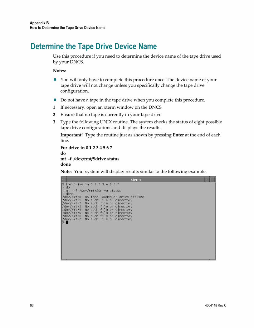
Appendix B How to Determine the Tape Drive Device Name
96 4004148 Rev C
Determine the Tape Drive Device Name Use this procedure if you need to determine the device name of the tape drive used by your DNCS.
Notes:
You will only have to complete this procedure once. The device name of your tape drive will not change unless you specifically change the tape drive configuration.
Do not have a tape in the tape drive when you complete this procedure.
1 If necessary, open an xterm window on the DNCS.
2 Ensure that no tape is currently in your tape drive.
3 Type the following UNIX routine. The system checks the status of eight possible tape drive configurations and displays the results.
Important! Type the routine just as shown by pressing Enter at the end of each line.
For drive in 0 1 2 3 4 5 6 7 do mt -f /dev/rmt/$drive status done
Note: Your system will display results similar to the following example.
Determine the Tape Drive Device Name
4004148 Rev C 97
4 Examine your results and use the following observations, based upon the example used in step 3, to determine the device name of your tape drive:
In the example in step 3, no tape drives are detected in /dev/rmt/1 through /dev/rmt/7 (as indicated by No such file or directory). Therefore, you can conclude that /dev/rmt/1 through /dev/rmt/7 are not valid device names for tape drives on the system queried in step 3.
In the example in step 3, a tape drive is detected in /dev/rmt/0 and the system accurately notes that no tape is loaded. Therefore, you can conclude that the device name of the tape drive on the system queried in step 3 is /dev/rmt/0.
If /dev/rmt/1 is the device name of your tape drive, then no tape loaded or
drive offline would appear next to /dev/rmt/1.
5 Write the device name of your tape drive in the space provided.
____________________

4004148 Rev C 99
C Appx auto letter Appendix C Direct ASI Installation and Configuration Procedures
Introduction
To reduce network infrastructure complexity, Cisco has removed the requirement for a Broadband Integrated Gateway (BIG) to transmit Broadcast File System (BFS) data to QAMs. The BFS now produces a full transport stream, and no longer feeds an MPEG stream to the BIG for further processing and multiplexing.
The DNCS is now configurable so that inband data can be transmitted through the current asynchronous transfer mode (ATM) interface or through a new asynchronous serial interface (ASI). This appendix provides instructions for installing and configuring the ASI.
100 4004148 Rev C
In This Appendix
Check for the Existence of the ASI Package .................................... 101
Enable the ASI Feature ....................................................................... 102
Stop the System Components ........................................................... 103
Install the ASI Card ............................................................................ 106
Install the ASI Package ....................................................................... 108
Configure the ASI Card ..................................................................... 109
Check the Status of the ASI Card ..................................................... 110
Restart System Components ............................................................. 111
Record Configuration Data ............................................................... 114
Create an MPEG Source ..................................................................... 117
Set Up the QAM .................................................................................. 120
Set Up the BFS Host ............................................................................ 123
Set the BIG Offline .............................................................................. 126
Stop the BFS and OSM Processes ..................................................... 127
Tear Down BFS Sessions .................................................................... 130
Clear Completed, Pending, or Failed Sessions ............................... 131
Enable the System for ASI ................................................................. 132
Restart the BFS and OSM Processes ................................................. 134
Checkout Procedures for the ASI Card ........................................... 136
Check for the Existence of the ASI Package
4004148 Rev C 101
Check for the Existence of the ASI Package
Checking for the Existence of the ASI Package on the DNCS
Before installing the ASI card, determine whether the ASI package currently exists on the DNCS. If it currently exists on the DNCS, you will have to remove it because a new ASI package cannot successfully install over an existing ASI package. Follow these instructions to check for the ASI package and then to remove it, if necessary.
Notes:
Be sure that you have the CD containing the old ASI package before deleting the package from the DNCS. You may need the old software should you ever have to roll back from an unsuccessful upgrade.
Normally, systems without an ASI card should not have an ASI package.
1 If necessary, open an xterm window on the DNCS.
2 Type pkginfo -l SAIasi and then press Enter. The system displays information about the ASI package, if it exists.
3 After completing step 2, did the ASI package exist on the DNCS?
If yes, go to step 4 to begin removing the package.
If no, go to Enable the ASI Feature (on page 102).
4 Follow these instructions to log on to the xterm window as root user.
a Type su - and then press Enter. The password prompt appears.
b Type the root password and then press Enter.
5 Type pkgrm SAIasi and then press Enter. The system removes the ASI package from the DNCS.
6 Go to Enable the ASI Feature (on page 102).
Appendix C Direct ASI Installation and Configuration Procedures
102 4004148 Rev C
Enable the ASI Feature
Enabling the ASI Feature
After removing the ASI package from the DNCS, contact Cisco Services. Engineers at Cisco Services will enable the Direct ASI feature.
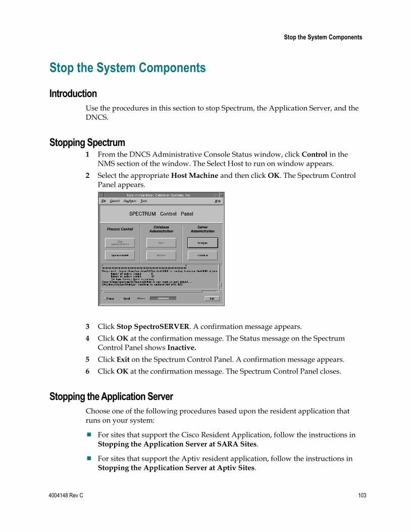
Stop the System Components
4004148 Rev C 103
Stop the System Components
Introduction
Use the procedures in this section to stop Spectrum, the Application Server, and the DNCS.
Stopping Spectrum 1 From the DNCS Administrative Console Status window, click Control in the
NMS section of the window. The Select Host to run on window appears.
2 Select the appropriate Host Machine and then click OK. The Spectrum Control Panel appears.
3 Click Stop SpectroSERVER. A confirmation message appears.
4 Click OK at the confirmation message. The Status message on the Spectrum Control Panel shows Inactive.
5 Click Exit on the Spectrum Control Panel. A confirmation message appears.
6 Click OK at the confirmation message. The Spectrum Control Panel closes.
Stopping the Application Server
Choose one of the following procedures based upon the resident application that runs on your system:
For sites that support the Cisco Resident Application, follow the instructions in Stopping the Application Server at SARA Sites.
For sites that support the Aptiv resident application, follow the instructions in Stopping the Application Server at Aptiv Sites.
Appendix C Direct ASI Installation and Configuration Procedures
104 4004148 Rev C
Stopping the Application Server at SARA Sites
Complete these steps to stop the Application Server at sites that support the Cisco resident application.
1 Press the middle mouse button on the Application Server and select App Serv
Stop.
2 From an xterm window on the Application Server, type appControl and then press Enter. The Applications Control window appears.
3 Type 2 (for Startup/Shutdown Single Element Group), and then press Enter. The system displays all Application Server processes.
Note: The system updates the display periodically, or you can press Enter to force an update.
4 When the Curr Stt (Current State) field of the Applications Control window indicates that all of the Application Server processes have stopped, follow the on-screen instructions to close the Applications Control window.
Shutting Down the Cisco Application Server
After stopping the Cisco Application Server, follow these steps to stop the Application Server.
1 Log on to an xterm window on the Application Server as root user.
2 Type /usr/sbin/shutdown -i0 -g0 -y and then press Enter. The Application Server shuts down and the ok prompt appears.
Stopping the Application Server at Aptiv Sites
Complete these steps to stop the Application Server at sites that support the Aptiv resident application.
1 Press the middle mouse button on the Application Server and select Passport
Stop.
2 From an xterm window on the Application Server, type CheckServices and then press Enter. A list of drivers appears.
Note: Each driver is associated with an Application Server process.
3 Wait until the word No appears next to each driver.
4 Log in to an xterm window as root user.
5 Type init 0 and then press Enter. The Application Server shuts down and an ok prompt appears.
Stop the System Components
4004148 Rev C 105
Stopping the DNCS 1 At the DNCS, press the middle mouse button and then select DNCS Stop. A
confirmation message appears.
2 Click Yes.
3 From an xterm window on the DNCS, type dncsControl and then press Enter. The Dncs Control window appears.
4 Type 2 (for Startup/Shutdown Single Element Group), and then press Enter. The system displays all DNCS processes.
Note: The system updates the display periodically, or you can press Enter to force an update.
5 When the Curr Stt (Current State) field of the Dncs Control window indicates that all of the DNCS processes have stopped, follow the on-screen instructions to close the Dncs Control window.
Appendix C Direct ASI Installation and Configuration Procedures
106 4004148 Rev C
Install the ASI Card
Installing the ASI Card
The Common Download feature requires that a special card be installed in the DNCS. Sites that support both the Direct ASI feature, as well as the Common Download feature, may find it convenient to install the Common Download card at the same time that the Direct ASI card is installed. For this reason, information pertaining to the Common Download card is included in step 4.
After deleting (if necessary) the ASI package from the DNCS, follow the instructions in this section to install the ASI card.
1 Follow these instructions, if necessary, to log in to the xterm window as root user.
Note: If you had to remove the ASI package in the previous procedure, you should already be root user.
a Type su - and then press Enter. The password prompt appears.
b Type the root password and then press Enter.
2 Type shutdown -y -g0 -i0 and then press Enter. The DNCS shuts down and the ok prompt appears.
3 Turn off power to the DNCS.
4 Remove the cover to the DNCS and install the ASI card into one of the following slots:
For a Enterprise 250 DNCS, Slot 2
For a Enterprise 450 DNCS, Slot 5
For a Sun Fire V880 DNCS, Slot 7
5 Is your site you upgrading to support the common download feature?
If yes, then install the common download card in the following slot:
– For a Sun Fire V880 DNCS, Slot 2
– For a Enterprise 450 DNCS, Slot 4
If no, go to step 6.
6 Put the cover back on the DNCS.
7 Turn on power to the DNCS.

Install the ASI Card
4004148 Rev C 107
8 Log on to the DNCS as root user.
9 Did the DNCS processes start after you turned on the power?
If yes, go to Stopping the DNCS (on page 40). Then, go to Install the ASI Package (on page 108).
If no, go to Install the ASI Package (on page 108).
Appendix C Direct ASI Installation and Configuration Procedures
108 4004148 Rev C
Install the ASI Package
Installing the ASI Package
After installing the ASI card into the DNCS, follow these instructions to install the ASI package.
Note: If you have properly followed the instructions in the previous procedure, you should be logged on as root user to the DNCS.
1 Type . /dvs/dncs/bin/dncsSetup and then press Enter. The system establishes the root user environment.
Important! Be sure to type the dot followed by a space prior to typing /dvs.
2 Insert the CD labeled similarly to SAIasi into the cdrom drive of the DNCS.
3 Type df -n and then press Enter. A list of the mounted filesystems appears.
Note: The presence of /cdrom in the output confirms that the system correctly mounted the CD.
4 Type cd /cdrom/cdrom0 and then press Enter.
5 Type install_pkg and then press Enter. Software installs which prepares the DNCS for Direct ASI support.
6 Type eject cd and then press Enter. The CD ejects from the DNCS.
7 Go to Configure the ASI Card (on page 109).
Configure the ASI Card
4004148 Rev C 109
Configure the ASI Card
Configuring the ASI Card
Now that you have installed the ASI package, follow these instructions to configure the ASI card.
1 Type cd /dvs/dncs/bin and then press Enter. The /dvs/dncs/bin directory becomes the working directory.
2 Type ./configureASI.pl and then press Enter. If the configuration script detects a problem with how the card is configured, the script displays a message seeking confirmation to correct the problem.
3 Type y and then press Enter. The system modifies the configuration of the Direct ASI card and prompts you to reboot the computer.
4 Type /usr/sbin/shutdown -g0 -i6 -y and then press Enter. The DNCS reboots.
5 Log in to the DNCS as dncs user.
6 At the ok prompt on the Application Server, type boot.
7 Log in to the Application Server as dncs user.
8 Go to Check the Status of the ASI Card (on page 110).
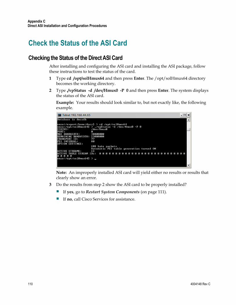
Appendix C Direct ASI Installation and Configuration Procedures
110 4004148 Rev C
Check the Status of the ASI Card
Checking the Status of the Direct ASI Card
After installing and configuring the ASI card and installing the ASI package, follow these instructions to test the status of the card.
1 Type cd /opt/solHmux64 and then press Enter. The /opt/solHmux64 directory becomes the working directory.
2 Type ./vpStatus -d /dev/Hmux0 -P 0 and then press Enter. The system displays the status of the ASI card.
Example: Your results should look similar to, but not exactly like, the following example.
Note: An improperly installed ASI card will yield either no results or results that clearly show an error.
3 Do the results from step 2 show the ASI card to be properly installed?
If yes, go to Restart System Components (on page 111).
If no, call Cisco Services for assistance.
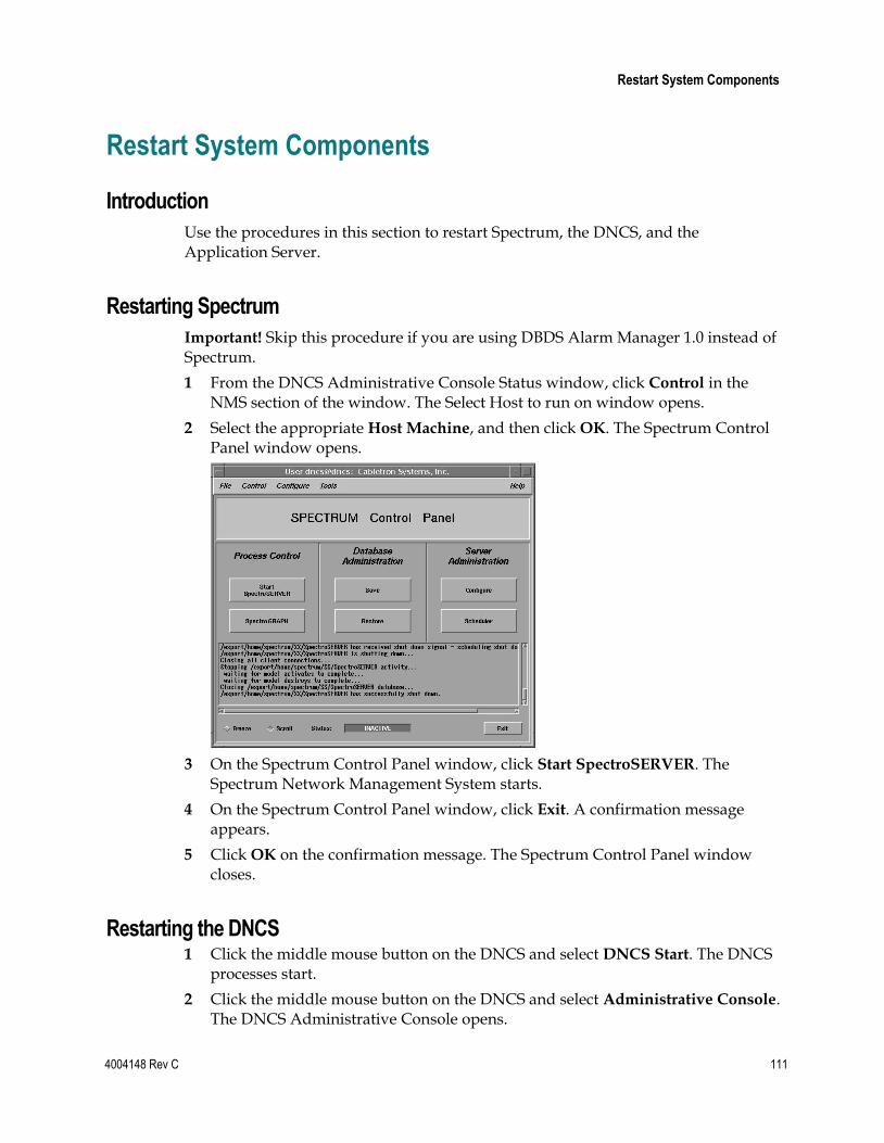
Restart System Components
4004148 Rev C 111
Restart System Components
Introduction
Use the procedures in this section to restart Spectrum, the DNCS, and the Application Server.
Restarting Spectrum
Important! Skip this procedure if you are using DBDS Alarm Manager 1.0 instead of Spectrum.
1 From the DNCS Administrative Console Status window, click Control in the NMS section of the window. The Select Host to run on window opens.
2 Select the appropriate Host Machine, and then click OK. The Spectrum Control Panel window opens.
3 On the Spectrum Control Panel window, click Start SpectroSERVER. The Spectrum Network Management System starts.
4 On the Spectrum Control Panel window, click Exit. A confirmation message appears.
5 Click OK on the confirmation message. The Spectrum Control Panel window closes.
Restarting the DNCS 1 Click the middle mouse button on the DNCS and select DNCS Start. The DNCS
processes start.
2 Click the middle mouse button on the DNCS and select Administrative Console. The DNCS Administrative Console opens.
Appendix C Direct ASI Installation and Configuration Procedures
112 4004148 Rev C
3 From the DNCS Administrative Console Status window, click DNCS Control.
Results:
The DNCS Control window opens.
Green indicators begin to replace red indicators on the DNCS Control window.
4 From an xterm window on the DNCS, type dncsControl and then press Enter. The Dncs Control utility window opens.
5 Type 2 (for Startup / Shutdown Single Element Group) and then press Enter. The Dncs Control window updates to list the status of all of the processes and servers running on the DNCS.
6 Wait for the Dncs Control window to list the current status (Curr Stt) of all the processes and servers as running.
Notes:
The Dncs Control window updates automatically every few seconds or you can press Enter to force an update.
The indicators on the DNCS Control window all become green when the processes and servers have restarted.
Restarting the Application Server
This section provides procedures for restarting either a SARA Server or an Aptiv Application Server. Choose the procedure that pertains to your system.
Restarting the Application Server at SARA Sites
1 Press the middle mouse button on the Application Server and select App Serv
Start.
2 From an xterm window on the Application Server, type appControl and then press Enter. The Applications Control window opens.
3 Select option 2 on the Applications Control window. The system displays a list of Application Server processes and their current status.
Note: The system updates the display periodically, or you can press Enter to force an update.
4 When the Application Control window indicates that the current state (Curr Stt) of each process is stopped, follow the on-screen instructions to close the Applications Control window.
Restart System Components
4004148 Rev C 113
Restarting the Application Server at Aptiv Sites
Complete the following steps to verify that the Passport resident application has started on the Application Server, and then to start it, if necessary.
1 Open an xterm window on the Application Server.
2 Type CheckServices and then press Enter. A list of drivers appears.
Note: Each driver is associated with an Application Server process.
3 Does the word Yes appear next to each driver, indicating that the process has started?
If yes, you have completed this procedure.
If no, go to step 4.
4 Press the middle mouse button, and then select Passport Start.
5 When the word Yes appears next to each driver, go to step 6.
6 Follow the on-screen instructions to close the window containing the list of drivers associated with the Passport resident application.
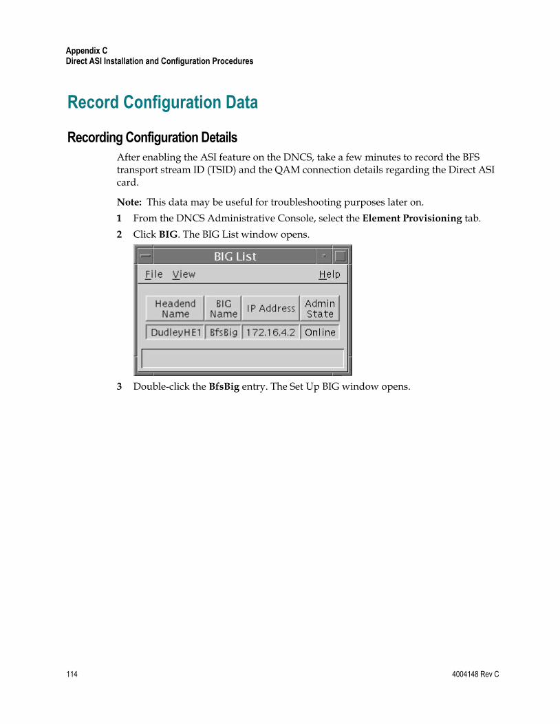
Appendix C Direct ASI Installation and Configuration Procedures
114 4004148 Rev C
Record Configuration Data
Recording Configuration Details
After enabling the ASI feature on the DNCS, take a few minutes to record the BFS transport stream ID (TSID) and the QAM connection details regarding the Direct ASI card.
Note: This data may be useful for troubleshooting purposes later on.
1 From the DNCS Administrative Console, select the Element Provisioning tab.
2 Click BIG. The BIG List window opens.
3 Double-click the BfsBig entry. The Set Up BIG window opens.
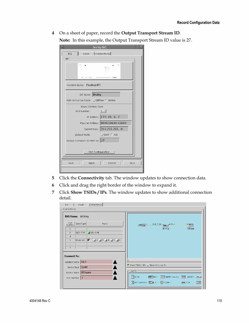
Record Configuration Data
4004148 Rev C 115
4 On a sheet of paper, record the Output Transport Stream ID.
Note: In this example, the Output Transport Stream ID value is 27.
5 Click the Connectivity tab. The window updates to show connection data.
6 Click and drag the right border of the window to expand it.
7 Click Show TSIDs / IPs. The window updates to show additional connection detail.
Appendix C Direct ASI Installation and Configuration Procedures
116 4004148 Rev C
8 Click the SWIF Transmit or Msync ASI port currently connected to the BFS QAM. In the Connect To area of the window, the system displays the Headend
Name, Device Type, Device Name, and Port Number.
9 In the space provided, record the data displayed in step 8.
Headend Name: ____________________
Device Type: ____________________
Device Name: ____________________
Port Number: ____________________
10 Click Cancel to close the window.
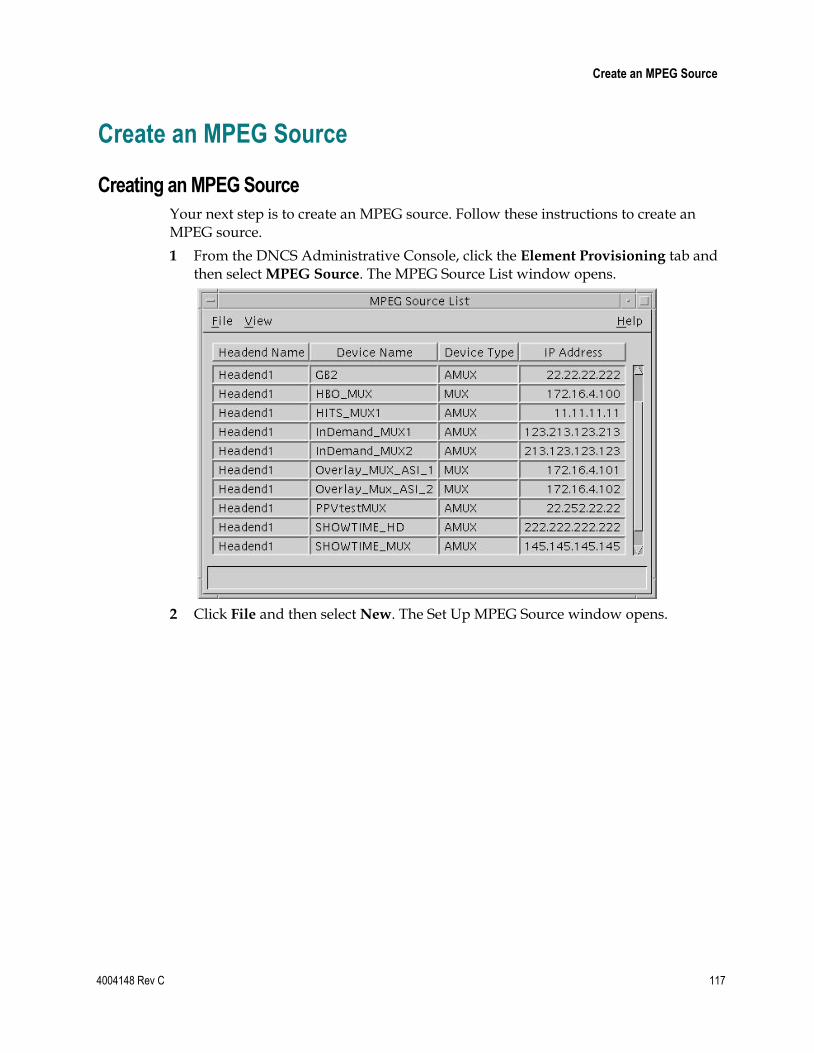
Create an MPEG Source
4004148 Rev C 117
Create an MPEG Source
Creating an MPEG Source
Your next step is to create an MPEG source. Follow these instructions to create an MPEG source.
1 From the DNCS Administrative Console, click the Element Provisioning tab and then select MPEG Source. The MPEG Source List window opens.
2 Click File and then select New. The Set Up MPEG Source window opens.
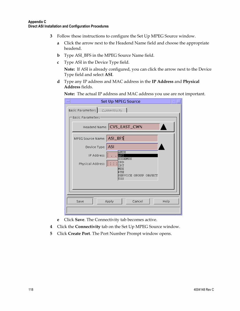
Appendix C Direct ASI Installation and Configuration Procedures
118 4004148 Rev C
3 Follow these instructions to configure the Set Up MPEG Source window.
a Click the arrow next to the Headend Name field and choose the appropriate headend.
b Type ASI_BFS in the MPEG Source Name field.
c Type ASI in the Device Type field.
Note: If ASI is already configured, you can click the arrow next to the Device Type field and select ASI.
d Type any IP address and MAC address in the IP Address and Physical
Address fields.
Note: The actual IP address and MAC address you use are not important.
e Click Save. The Connectivity tab becomes active.
4 Click the Connectivity tab on the Set Up MPEG Source window.
5 Click Create Port. The Port Number Prompt window opens.
Create an MPEG Source
4004148 Rev C 119
6 Follow these instructions to configure the Port Number Prompt window.
a In the Output Port field, type 0 (zero).
b In the TSID field, type a transport stream ID (TSID) that is equal to the input TSID for the BFS QAM.
c If the Transport Protocol field does not display ASI, click the arrow to the right of the field and select ASI.
d Click OK. The Set Up MPEG Source window reappears and the new configuration is saved.
7 Click Close. The Set Up MPEG Source window closes.
8 Go to Set Up the QAM (on page 120).
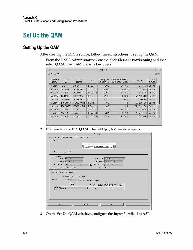
Appendix C Direct ASI Installation and Configuration Procedures
120 4004148 Rev C
Set Up the QAM
Setting Up the QAM
After creating the MPEG source, follow these instructions to set up the QAM.
1 From the DNCS Administrative Console, click Element Provisioning and then select QAM. The QAM List window opens.
2 Double-click the BFS QAM. The Set Up QAM window opens.
3 On the Set Up QAM window, configure the Input Port field to ASI.
Set Up the QAM
4004148 Rev C 121
4 Configure the INPUT Transport Stream ID field with the same value that you recorded as the TSID on the Set Up MPEG Source window in a previous procedure, Creating an MPEG Source (on page 117).
5 Click the Connectivity tab.
6 In the Connect To area of the window, click the arrow to the right of each of the following fields and set each field to none:
Device Type
Device Name
Card Type
Slot Number
Port Number
Note: The system requires that you first set these fields to none before you change the configuration.
7 Click Save.
Important! If the Save button is unavailable after completing step 7, close the Set Up QAM window. Then, double-click the BFS QAM from the QAM List window to gain access again to the Set Up QAM window.
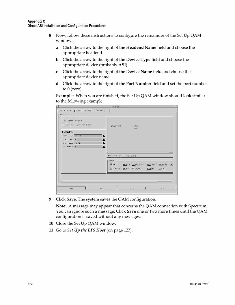
Appendix C Direct ASI Installation and Configuration Procedures
122 4004148 Rev C
8 Now, follow these instructions to configure the remainder of the Set Up QAM window.
a Click the arrow to the right of the Headend Name field and choose the appropriate headend.
b Click the arrow to the right of the Device Type field and choose the appropriate device (probably ASI).
c Click the arrow to the right of the Device Name field and choose the appropriate device name.
d Click the arrow to the right of the Port Number field and set the port number to 0 (zero).
Example: When you are finished, the Set Up QAM window should look similar to the following example.
9 Click Save. The system saves the QAM configuration.
Note: A message may appear that concerns the QAM connection with Spectrum. You can ignore such a message. Click Save one or two more times until the QAM configuration is saved without any messages.
10 Close the Set Up QAM window.
11 Go to Set Up the BFS Host (on page 123).
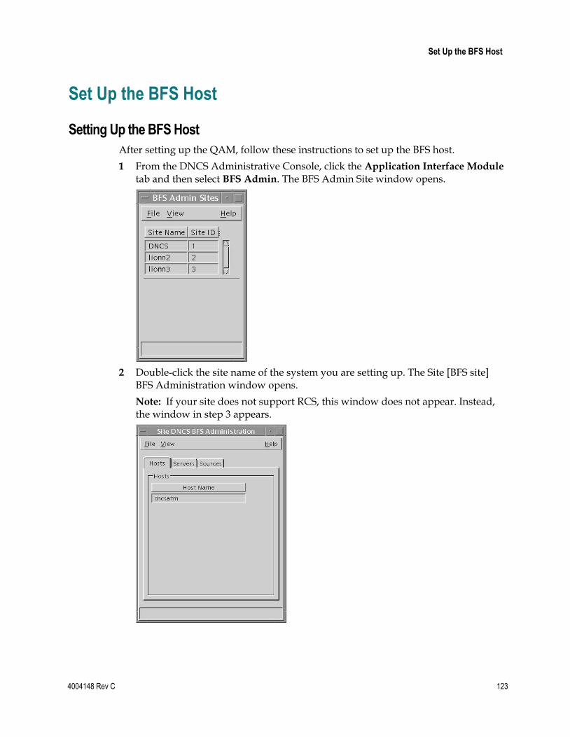
Set Up the BFS Host
4004148 Rev C 123
Set Up the BFS Host
Setting Up the BFS Host
After setting up the QAM, follow these instructions to set up the BFS host.
1 From the DNCS Administrative Console, click the Application Interface Module tab and then select BFS Admin. The BFS Admin Site window opens.
2 Double-click the site name of the system you are setting up. The Site [BFS site] BFS Administration window opens.
Note: If your site does not support RCS, this window does not appear. Instead, the window in step 3 appears.
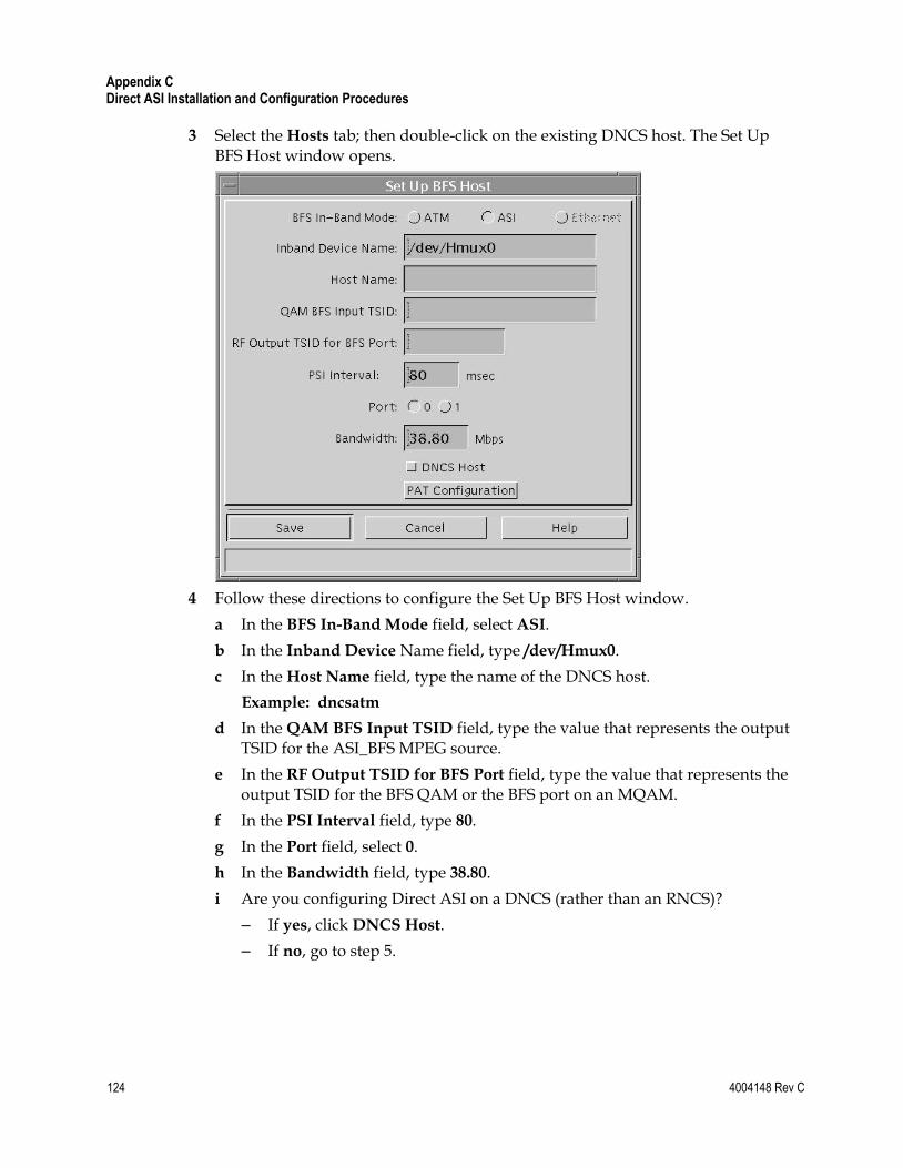
Appendix C Direct ASI Installation and Configuration Procedures
124 4004148 Rev C
3 Select the Hosts tab; then double-click on the existing DNCS host. The Set Up BFS Host window opens.
4 Follow these directions to configure the Set Up BFS Host window.
a In the BFS In-Band Mode field, select ASI.
b In the Inband Device Name field, type /dev/Hmux0.
c In the Host Name field, type the name of the DNCS host.
Example: dncsatm
d In the QAM BFS Input TSID field, type the value that represents the output TSID for the ASI_BFS MPEG source.
e In the RF Output TSID for BFS Port field, type the value that represents the output TSID for the BFS QAM or the BFS port on an MQAM.
f In the PSI Interval field, type 80.
g In the Port field, select 0.
h In the Bandwidth field, type 38.80.
i Are you configuring Direct ASI on a DNCS (rather than an RNCS)?
– If yes, click DNCS Host.
– If no, go to step 5.

Set Up the BFS Host
4004148 Rev C 125
5 Click PAT Configuration. The Inband Data PAT window opens.
6 Click Close on the Inband Data PAT window.
7 Click Save on the Set Up BFS Host window. The system saves the BFS host configuration.
8 Go to Setting the BIG Offline (on page 126).
Appendix C Direct ASI Installation and Configuration Procedures
126 4004148 Rev C
Set the BIG Offline
Setting the BIG Offline
After setting up the BFS source, follow these instructions to set the BIG offline.
CAUTION:
Never delete the BIG. You need the BIG if you ever have to roll back the install of Direct ASI.
1 From the DNCS Administrative Console, select the Element Provisioning tab.
2 Click BIG. The BIG List window opens.
3 Double-click the BIG. The Set Up BIG window opens.
4 At the Administrative Status field, select Offline.
5 Click Save. The system saves the BIG status to be offline.
6 Go to Stop the BFS and OSM Processes (on page 127).
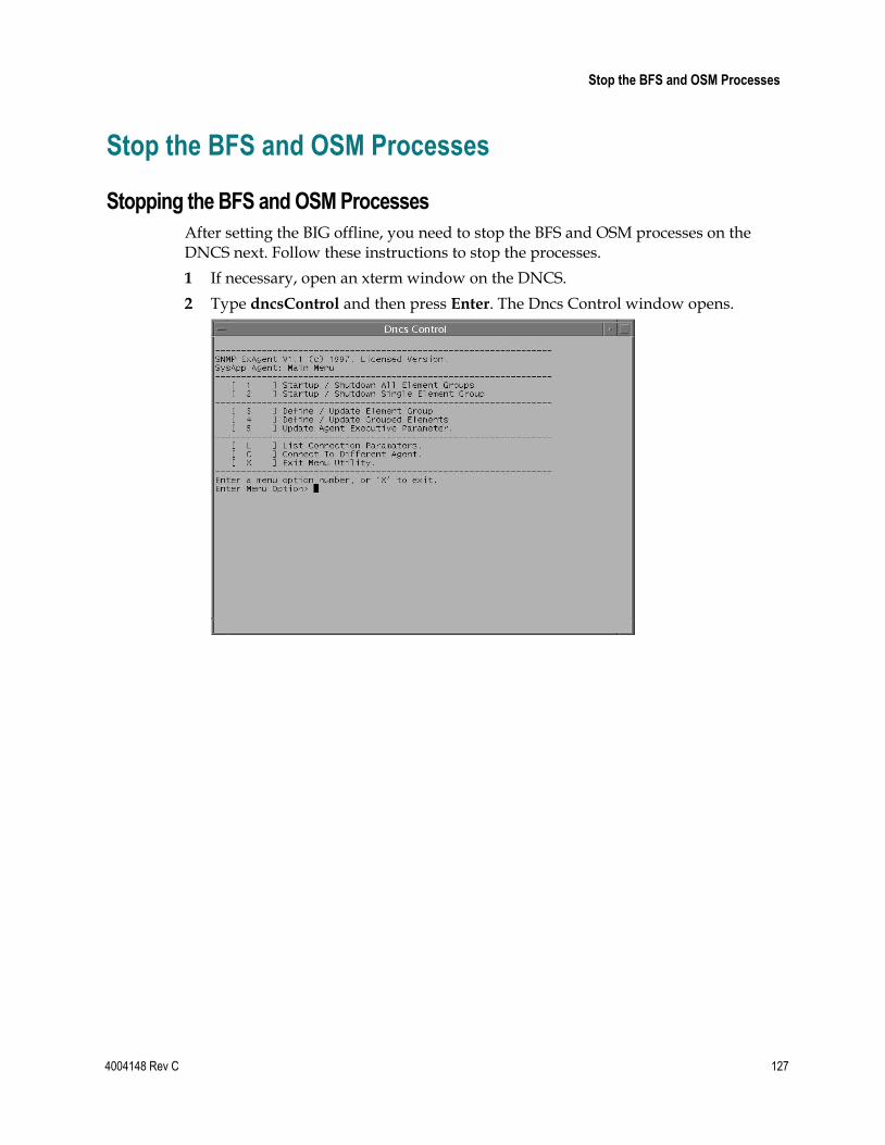
Stop the BFS and OSM Processes
4004148 Rev C 127
Stop the BFS and OSM Processes
Stopping the BFS and OSM Processes
After setting the BIG offline, you need to stop the BFS and OSM processes on the DNCS next. Follow these instructions to stop the processes.
1 If necessary, open an xterm window on the DNCS.
2 Type dncsControl and then press Enter. The Dncs Control window opens.
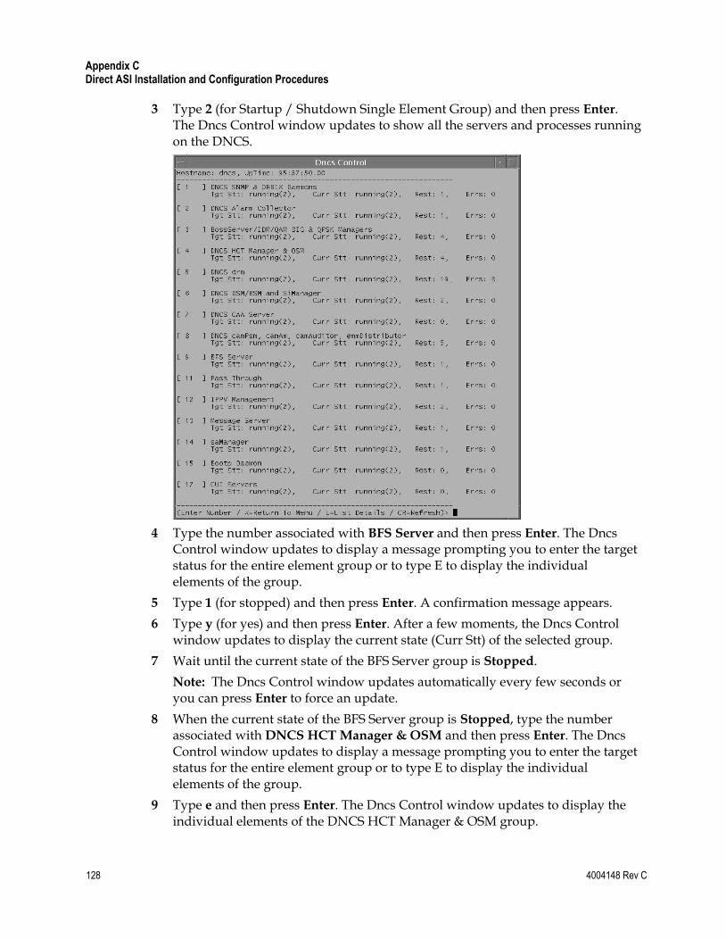
Appendix C Direct ASI Installation and Configuration Procedures
128 4004148 Rev C
3 Type 2 (for Startup / Shutdown Single Element Group) and then press Enter. The Dncs Control window updates to show all the servers and processes running on the DNCS.
4 Type the number associated with BFS Server and then press Enter. The Dncs Control window updates to display a message prompting you to enter the target status for the entire element group or to type E to display the individual elements of the group.
5 Type 1 (for stopped) and then press Enter. A confirmation message appears.
6 Type y (for yes) and then press Enter. After a few moments, the Dncs Control window updates to display the current state (Curr Stt) of the selected group.
7 Wait until the current state of the BFS Server group is Stopped.
Note: The Dncs Control window updates automatically every few seconds or you can press Enter to force an update.
8 When the current state of the BFS Server group is Stopped, type the number associated with DNCS HCT Manager & OSM and then press Enter. The Dncs Control window updates to display a message prompting you to enter the target status for the entire element group or to type E to display the individual elements of the group.
9 Type e and then press Enter. The Dncs Control window updates to display the individual elements of the DNCS HCT Manager & OSM group.
Stop the BFS and OSM Processes
4004148 Rev C 129
10 Type the number associated with /dvs/dncs/bin/OSM and then press Enter. The Dncs Control window updates to display a message prompting you to enter the target status of the selected element.
11 Type 1 (for stopped) and then press Enter. A confirmation message appears.
12 Type y (for yes) and then press Enter. After a few moments, the Dncs Control window updates to display the current state (Curr Stt) of the selected element.
13 Wait until the current state of the /dvs/dncs/bin/OSM process is Stopped.
Note: The Dncs Control window updates automatically every few seconds or you can press Enter to force an update.
14 When the current state of the /dvs/dncs/bin/OSM process is Stopped, follow the on-screen instructions to exit from the dncsControl utility.
15 Go to Tear Down BFS Sessions (on page 130).
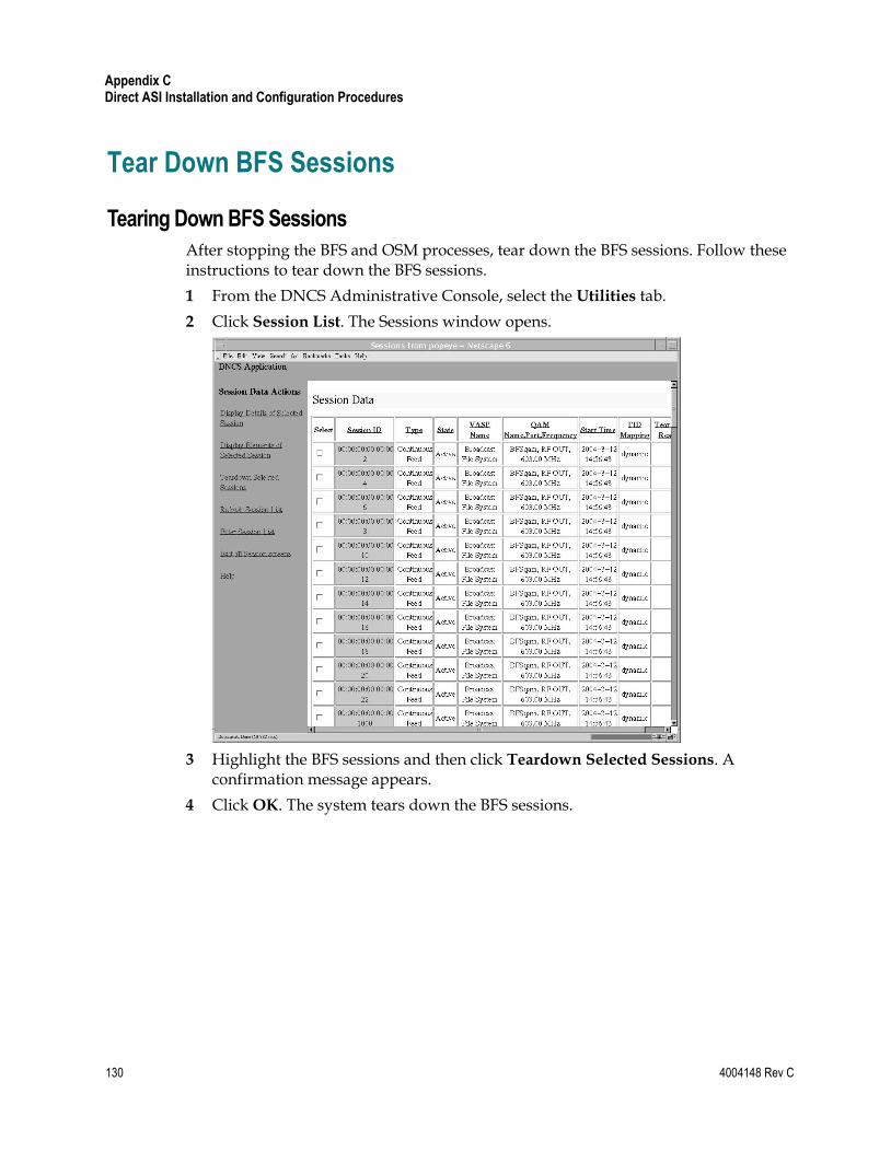
Appendix C Direct ASI Installation and Configuration Procedures
130 4004148 Rev C
Tear Down BFS Sessions
Tearing Down BFS Sessions
After stopping the BFS and OSM processes, tear down the BFS sessions. Follow these instructions to tear down the BFS sessions.
1 From the DNCS Administrative Console, select the Utilities tab.
2 Click Session List. The Sessions window opens.
3 Highlight the BFS sessions and then click Teardown Selected Sessions. A confirmation message appears.
4 Click OK. The system tears down the BFS sessions.
Clear Completed, Pending, or Failed Sessions
4004148 Rev C 131
Clear Completed, Pending, or Failed Sessions
Clearing Completed, Pending, or Failed Sessions
Follow these instructions to clear completed, pending, or failed sessions.
1 If necessary, open an xterm window on the DNCS.
2 Type clearDbSessions -c and then press Enter.
Important! Complete this step even if the Session List window, in the previous procedure—Tear Down BFS Sessions—shows no sessions.
Appendix C Direct ASI Installation and Configuration Procedures
132 4004148 Rev C
Enable the System for ASI
Introduction
To finally enable your system for Direct ASI, there are a few more steps you need to complete. These steps are detailed in the following sections.
Enable ASI From the DNCS GUI
Follow these instructions to configure the BFS QAM for ASI.
1 From the DNCS Administrative Console, select the Element Provisioning tab.
2 Click QAM. The QAM List opens.
3 Double-click the BFS QAM. The Set Up QAM window opens.
4 At the Ports field, select ASI.
5 Click Save.
6 Click Close. The Set Up QAM window closes.
7 Click File and then select Close on the QAM List window.
Reset the BFS QAM
Reset the BFS QAM, using one of the following methods:
The DNCS GUI
The front panel of the BFS QAM
The auditQam Utility
Enable the System for ASI
4004148 Rev C 133
Inspect the Front Panel of the BFS QAM
In this procedure, you will inspect the front panel of the BFS QAM to confirm that the BFS QAM is indeed configured for ASI. If the front panel reveals that the BFS QAM is not configured for ASI, you need to manually configure it. The following procedure guides you through the necessary steps.
1 Press the Options button on the front panel of the BFS QAM until Input
Selection appears.
2 Does the Input Selection field reveal that the BFS QAM is configured for ASI?
If yes, skip the remainder of this procedure and go to Re-Cable the System for ASI (on page 133).
If no, continue with step 3.
3 Press the up or down arrow button until ASI appears in the Input Selection field.
4 Press Enter to save the newly configured BFS QAM.
Re-Cable the System for ASI
Now that the BFS QAM is configured for ASI, your next step is to configure the cabling of the BFS QAM. Follow these instructions to re-cable the system for ASI.
1 Remove the SWIF cable from the back of the BFS QAM.
2 Connect one end of the ASI cable to the back of the BFS QAM and connect the other end to the ASI connector on the back of the DNCS.
Re-Check the BFS QAM
Check the front panel of the BFS QAM periodically for an hour, or so. Make sure that the Input Selection field still reads ASI. If it no longer reads ASI, reset it to ASI.
Appendix C Direct ASI Installation and Configuration Procedures
134 4004148 Rev C
Restart the BFS and OSM Processes
Restarting the BFS and OSM Processes
You are now ready to restart the BFS and OSM processes, which you stopped earlier in this appendix. Follow these instructions to restart the BFS and OSM processes.
Note: When you restart the BFS processes, the system rebuilds the PAT Configuration table. It may take up to 10 minutes for the PAT Configuration table to be rebuilt.
1 If necessary, open an xterm window on the DNCS.
2 Type dncsControl and then press Enter. The Dncs Control window opens.
3 Type 2 (for Startup / Shutdown Single Element Group) and then press Enter. The Dncs Control window updates to show all the servers and processes on the DNCS.
4 Type the number associated with BFS Server and then press Enter. The Dncs Control window updates to display a message prompting you to enter the target status for the entire element group or to type E to display the individual elements of the group.
5 Type 2 (for running) and then press Enter. A confirmation message appears.
6 Type y (for yes) and then press Enter. After a few moments, the Dncs Control window updates to display the current state (Curr Stt) of the selected group.
7 Wait until the current state of the BFS Server group is Running.
Note: The Dncs Control window updates automatically every few seconds or you can press Enter to force an update.
8 When the current state of the BFS Server group is Running, type the number associated with DNCS HCT Manager & OSM and then press Enter. The Dncs Control window updates to display a message prompting you to enter the target status for the entire element group or to type E to display the individual elements of the group.
9 Type e and then press Enter.
Note: The Dncs Control window updates to display the individual elements of the DNCS HCT Manager & OSM group.
10 Type the number associated with /dvs/dncs/bin/OSM and then press Enter. The Dncs Control window updates to display a message prompting you to enter the target status of the selected element.
Restart the BFS and OSM Processes
4004148 Rev C 135
11 Type 2 (for running) and then press Enter. A confirmation message appears.
12 Type y (for yes) and then press Enter. After a few moments, the Dncs Control window updates to display the current state (Curr Stt) of the selected element.
13 Wait until the current state of the /dvs/dncs/bin/OSM process is Running.
Note: The Dncs Control window updates automatically every few seconds or you can press Enter to force an update.
14 When the current state of the /dvs/dncs/bin/OSM process is Running, follow the on-screen instructions to exit from the dncsControl utility.
Powering Down the BFS BIG
Conclude your procedure for configuring your system for Direct ASI by turning off power to the BFS BIG.
Appendix C Direct ASI Installation and Configuration Procedures
136 4004148 Rev C
Checkout Procedures for the ASI Card
Introduction
After completing the procedures in this appendix to install and configure the ASI card, complete some or all of the tests in this section to confirm that the ASI card is working as intended. These tests are in outline form, only. Cisco assumes that upgrade engineers are familiar with the detail behind each test.
Confirming the Session Count
After completing the procedures in this appendix to install and configure the ASI card, complete some or all of the tests in this section to confirm that the ASI card is working as intended. These tests are only in outline form. Cisco assumes that upgrade engineers are familiar with the detail behind each test.
1 Press the Options button on the front panel of the BFS QAM until the Session
Count appears.
2 Confirm that the number of sessions on the BFS QAM is equal to the number of BFS sessions on the DNCS.
3 Re-run the procedures in Verify DBDS Stability (on page 22).
Verify DBDS Stability
Re-run the procedures in Verify DBDS Stability (on page 22).
4004148 Rev C 137
D Appx auto letter Appendix D Direct ASI Rollback Procedures
Introduction
Use the procedures in this appendix to roll a system back from an unsuccessful installation of Direct ASI.
Important: Never roll a system back without having first consulted with Cisco Services. In many cases, Cisco engineers can help you troubleshoot whatever problems you may have experienced with the installation of Direct ASI.
In This Appendix
Record TSID Values for BFS MPEG Source and BFS QAM .......... 138
Turn on the BIG ................................................................................... 140
Record Configuration Data ............................................................... 141
Set the BIG Online ............................................................................... 142
Reconfigure the QAM ........................................................................ 143
Reconnect the BIG ............................................................................... 145
Configure the Front Panel of the BFS QAM .................................... 146
Configure Inband Data ...................................................................... 147
Set Up DNCS Host .............................................................................. 148
Stop the BFS, OSM, and siManager Processes ................................ 149
Tear Down BFS Sessions .................................................................... 150
Clear Completed, Pending, or Failed Sessions ............................... 151
Stop the BFS QAM .............................................................................. 152
Restart the BFS, OSM, and siManager Processes ........................... 153
Restart the BFS QAM ......................................................................... 154
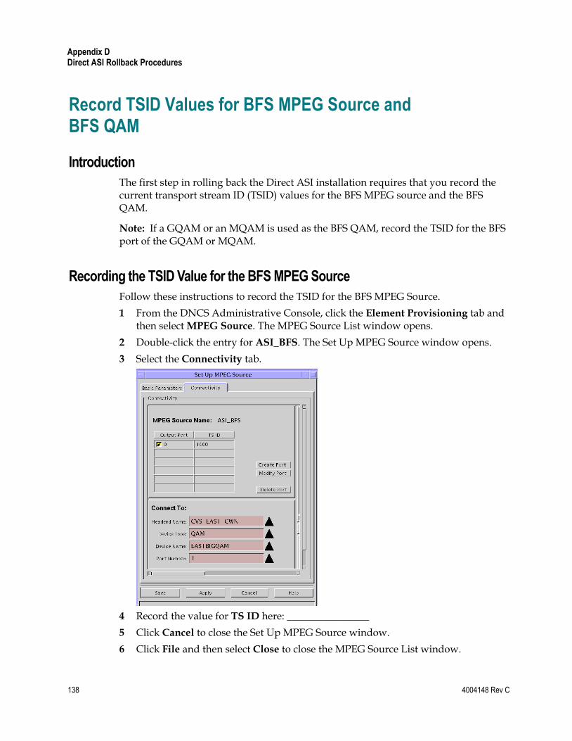
Appendix D Direct ASI Rollback Procedures
138 4004148 Rev C
Record TSID Values for BFS MPEG Source and BFS QAM
Introduction
The first step in rolling back the Direct ASI installation requires that you record the current transport stream ID (TSID) values for the BFS MPEG source and the BFS QAM.
Note: If a GQAM or an MQAM is used as the BFS QAM, record the TSID for the BFS port of the GQAM or MQAM.
Recording the TSID Value for the BFS MPEG Source
Follow these instructions to record the TSID for the BFS MPEG Source.
1 From the DNCS Administrative Console, click the Element Provisioning tab and then select MPEG Source. The MPEG Source List window opens.
2 Double-click the entry for ASI_BFS. The Set Up MPEG Source window opens.
3 Select the Connectivity tab.
4 Record the value for TS ID here: ________________
5 Click Cancel to close the Set Up MPEG Source window.
6 Click File and then select Close to close the MPEG Source List window.
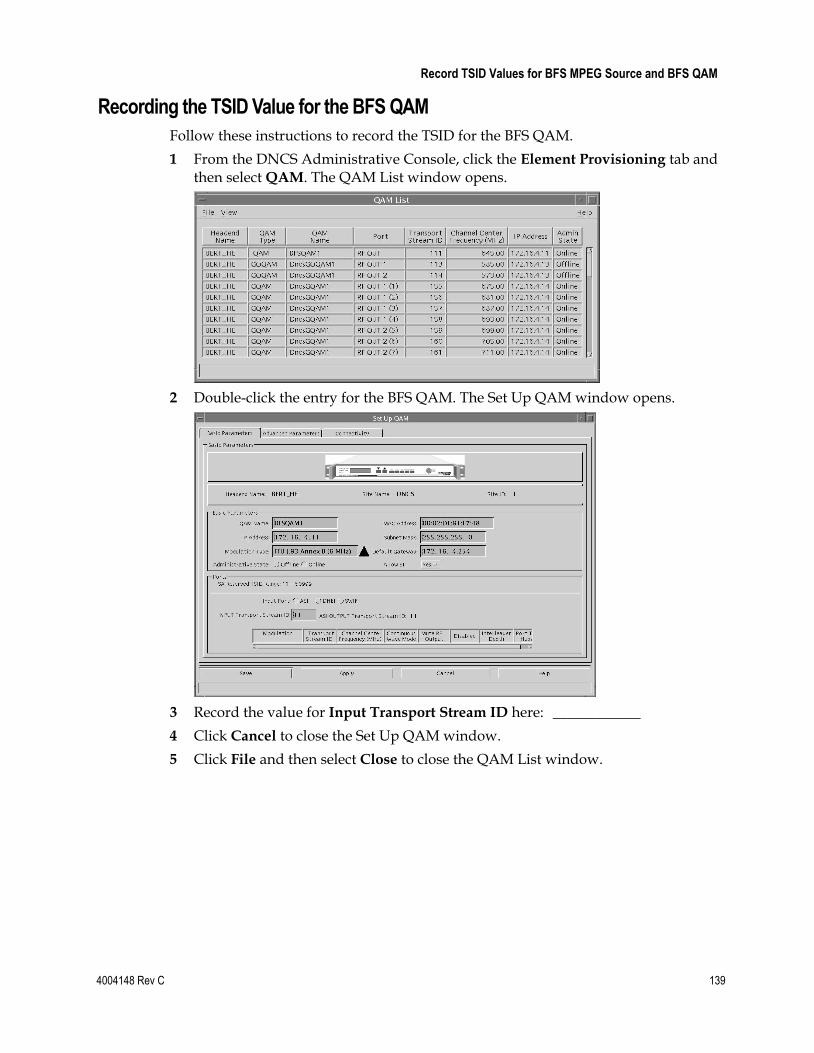
Record TSID Values for BFS MPEG Source and BFS QAM
4004148 Rev C 139
Recording the TSID Value for the BFS QAM
Follow these instructions to record the TSID for the BFS QAM.
1 From the DNCS Administrative Console, click the Element Provisioning tab and then select QAM. The QAM List window opens.
2 Double-click the entry for the BFS QAM. The Set Up QAM window opens.
3 Record the value for Input Transport Stream ID here: ____________
4 Click Cancel to close the Set Up QAM window.
5 Click File and then select Close to close the QAM List window.

Appendix D Direct ASI Rollback Procedures
140 4004148 Rev C
Turn on the BIG
Verify Power-up Sequence
Turn on the BIG and verify that the BIG goes through a power-up sequence. Various lights should illuminate. After about a minute, the BIG should settle into a steady state.
Record Configuration Data
4004148 Rev C 141
Record Configuration Data
Recording Configuration Details
When you configured your system for Direct ASI in Appendix C, one of the procedures called for you to record the BFS TSID and the QAM connection details regarding the Direct ASI card. If you failed to complete the Record Configuration Data (on page 114) procedure when you configured your system for Direct ASI, complete that procedure now.
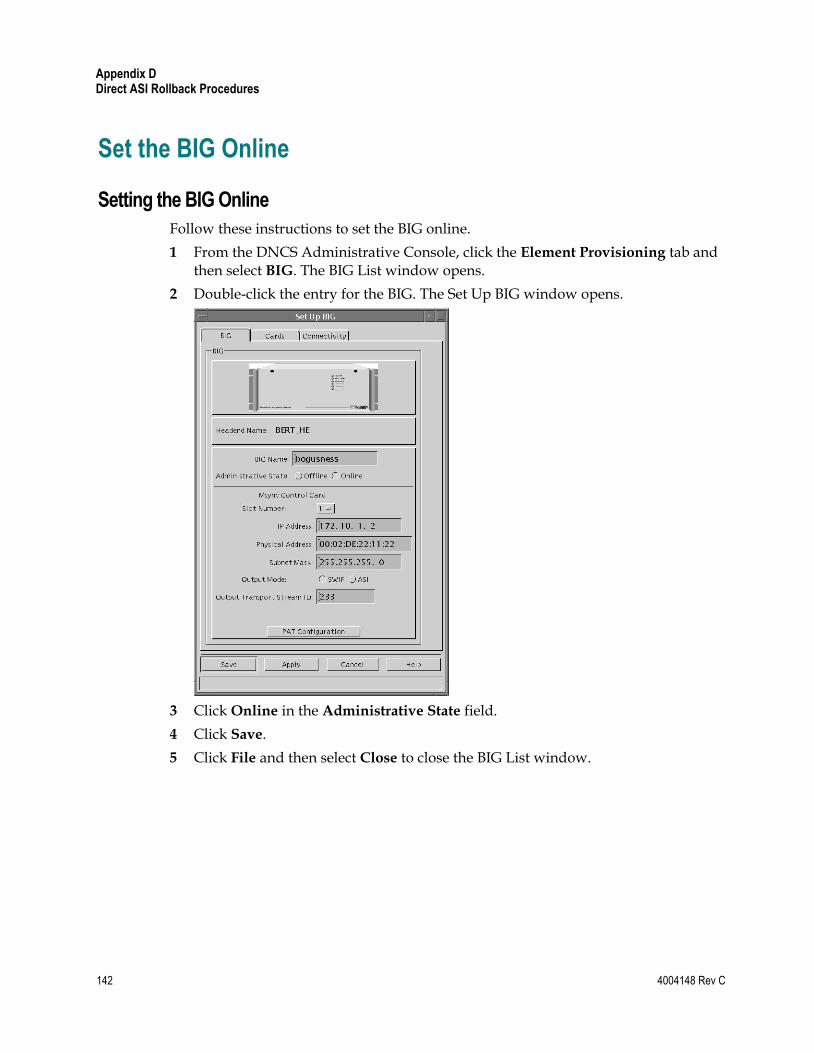
Appendix D Direct ASI Rollback Procedures
142 4004148 Rev C
Set the BIG Online
Setting the BIG Online
Follow these instructions to set the BIG online.
1 From the DNCS Administrative Console, click the Element Provisioning tab and then select BIG. The BIG List window opens.
2 Double-click the entry for the BIG. The Set Up BIG window opens.
3 Click Online in the Administrative State field.
4 Click Save.
5 Click File and then select Close to close the BIG List window.
Reconfigure the QAM
4004148 Rev C 143
Reconfigure the QAM
Reconfiguring the QAM
Follow these instructions to reconfigure the BFS QAM to support the rollback of Direct ASI.
1 From the DNCS Administrative Console, click the Element Provisioning tab and then select QAM. The QAM List window opens.
2 Double-click the entry for the BFS QAM. The Set Up QAM window opens.
3 Select the Connectivity tab.
4 In the Connect To area of the window, click the arrow to the right of each of the following fields and set each field to none:
Device Type
Device Name
Card Type
Slot Number
Port Number
5 Click Save.
6 Select the Basic Parameters tab on the Set Up QAM window.
7 In the Input Port field, select SWIF.
Exception: If your system uses ASI output from the Msync card, leave the Input Port field at ASI.
8 In the Input Transport Stream ID field, enter the value from the SWIF transmit card on the BIG.
Note: You can find this value by clicking Show TSIDs from the Connectivity tab of the Set Up BIG window.
9 Click Save.
10 Select the Connectivity tab again on the Set Up QAM window.
Appendix D Direct ASI Rollback Procedures
144 4004148 Rev C
11 Follow these instructions to configure the fields in the Connect To area of the window to support the BIG.
Note: Click the arrow to the right of each field to change the value of the field.
a Set the Device Type field to BIG.
b Set the Device Name field to match the name of the BFS BIG.
c Set the Card Type field to SWIF Transmit.
Exception: Select Msync if your system uses ASI output from the Msync card.
d Set the Slot Number field to whatever slot the SWIF transmit card is installed in the BIG.
e Set the Port Number field to the port used by the SWIF transmit card in the BIG.
12 Click Save.
13 Close the Set Up QAM window.
Reconnect the BIG
4004148 Rev C 145
Reconnect the BIG
Reconnecting the BIG
Follow these instructions to reconnect the input cable from the BFS QAM to the BIG.
1 Remove the ASI input cable from the back of the BFS QAM.
2 Reinstall the SWIF cable to the back of the BFS QAM.
Appendix D Direct ASI Rollback Procedures
146 4004148 Rev C
Configure the Front Panel of the BFS QAM
Configuring the Front Panel of the BFS QAM
In this procedure, you will inspect the front panel of the BFS QAM to confirm that the BFS QAM is indeed configured for SWIF. If the front panel reveals that the BFS QAM is not configured for SWIF, you need to manually configure it. The following procedure guides you through the necessary steps.
1 Press the Options button on the front panel of the BFS QAM until Input
Selection appears.
2 Does the Input Selection field reveal that the BFS QAM is configured for SWIF?
If yes, you have completed this procedure; go to Configure Inband Data (on page 147).
If no, continue with step 3.
3 Press the up or down arrow button until SWIF appears in the Input Selection field.
4 Press Enter to save the newly configured BFS QAM.
Configure Inband Data
4004148 Rev C 147
Configure Inband Data
Configuring Inband Data
After reconnecting the BIG, follow these instructions to configure inband data.
1 From the DNCS Administrative Console, select the Application Interface
Modules tab.
2 Click Inband Data Config. The Inband Data Configuration window opens.
3 In the BFS In-Band Mode field, select ATM.
4 Click Save.
5 Close the Inband Data Configuration window.
Appendix D Direct ASI Rollback Procedures
148 4004148 Rev C
Set Up DNCS Host
Setting Up the DNCS Host
Follow these instructions to configure the DNCS host.
1 From the DNCS Administrative Console, select the Application Interface
Modules tab.
2 Click BFS Admin. The BFS Administration window opens.
3 Select the Hosts tab.
4 Double-click dncsatm. The Set Up BFS Host window opens
Note: If this is a distributed site (supports the RNCS feature), double-click the DNCS site.
5 On the Set Up BFS Host window, confirm that the Host Name is dncsatm and that the other fields are empty.
6 Close the Set Up BFS Host window.
7 Select Sources on the BFS Administration window. The window updates to list all BFS sources.
8 Double-click Source ID 2. The Set Up BFS Source window opens.
9 On the Set Up BFS Source window, verify that the Transmit Type is In-band and that the Device Name is /dev/xtipvc0.
10 Click Save to close the Set Up BFS Source window.
11 Repeat steps 8 through 10 for all inband sources, plus any customized inband sources defined by the system operator.
Note: An inband source usually has the designation IB as part if its name.
Stop the BFS, OSM, and siManager Processes
4004148 Rev C 149
Stop the BFS, OSM, and siManager Processes
Stopping the BFS, OSM, and siManager Processes
You next need to stop the BFS, OSM, and siManager processes on the DNCS. Follow these instructions to stop the processes.
1 From the DNCS Control window, click to highlight the bfsRemote process.
2 Click Process and then select Stop Process. In a few minutes, the indicator for the bfsRemote process changes from green to red.
Important! Do not go to step 3 until the indicator has changed to red.
3 From the DNCS Control window, click to highlight the bfsServer process.
4 Click Process and then select Stop Process. In a few minutes, the indicator for the bfsServer process changes from green to red.
Important! Do not go to step 5 until the indicator has changed to red.
5 From the DNCS Control window, click to highlight the osm process.
6 Click Process and then select Stop Process. In a few minutes, the indicator for the osm process changes from green to red.
Important! Do not go to step 7 until the indicator has changed to red.
7 From the DNCS Control window, click to highlight the siManager process.
8 Click Process and then select Stop Process. In a few minutes, the indicator for the siManager process changes from green to red.
Important! Do not go to the next procedure until the indicator has changed to red.
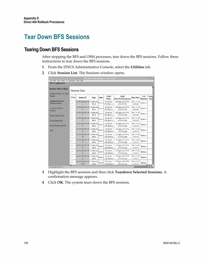
Appendix D Direct ASI Rollback Procedures
150 4004148 Rev C
Tear Down BFS Sessions
Tearing Down BFS Sessions
After stopping the BFS and OSM processes, tear down the BFS sessions. Follow these instructions to tear down the BFS sessions.
1 From the DNCS Administrative Console, select the Utilities tab.
2 Click Session List. The Sessions window opens.
3 Highlight the BFS sessions and then click Teardown Selected Sessions. A confirmation message appears.
4 Click OK. The system tears down the BFS sessions.

Clear Completed, Pending, or Failed Sessions
4004148 Rev C 151
Clear Completed, Pending, or Failed Sessions
Clearing Completed, Pending, or Failed Sessions
Follow these instructions to clear completed, pending, or failed sessions.
1 If necessary, open an xterm window on the DNCS.
2 Type clearDbSessions -c and then press Enter.
Important! Complete this step even if the Session List window, in the previous procedure—Tear Down BFS Sessions—shows no sessions.

Appendix D Direct ASI Rollback Procedures
152 4004148 Rev C
Stop the BFS QAM
Stopping the BFS QAM
After running the clearDbSessions command to clear completed, pending, or failed sessions, you need to turn off the BFS QAM. Locate the power switch on the back panel of the BFS QAM and set it to the Off position.
Restart the BFS, OSM, and siManager Processes
4004148 Rev C 153
Restart the BFS, OSM, and siManager Processes
Restarting the BFS, OSM, and siManager Processes
Follow these instructions to restart the BFS, OSM, and siManager processes.
1 From the DNCS Control window, click to highlight the bfsRemote process.
2 Click Process and then select Start Process. In a few minutes, the indicator for the bfsRemote process changes from red to green.
Important! Do not go to step 3 until the indicator has changed to green.
3 From the DNCS Control window, click to highlight the bfsServer process.
4 Click Process and then select Start Process. In a few minutes, the indicator for the bfsServer process changes from red to yellow.
Note: The bfsServer process will not show green because the BFS QAM is currently stopped.
Important! Do not go to step 5 until the indicator has changed to yellow.
5 From the DNCS Control window, click to highlight the osm process.
6 Click Process and then select Start Process. In a few minutes, the indicator for the osm process changes from red to green.
Important! Do not go to step 7 until the indicator has changed to green.
7 From the DNCS Control window, click to highlight the siManager process.
8 Click Process and then select Start Process. In a few minutes, the indicator for the siManager process changes from red to green.
Important! Do not go to the next procedure until the indicator has changed to green.
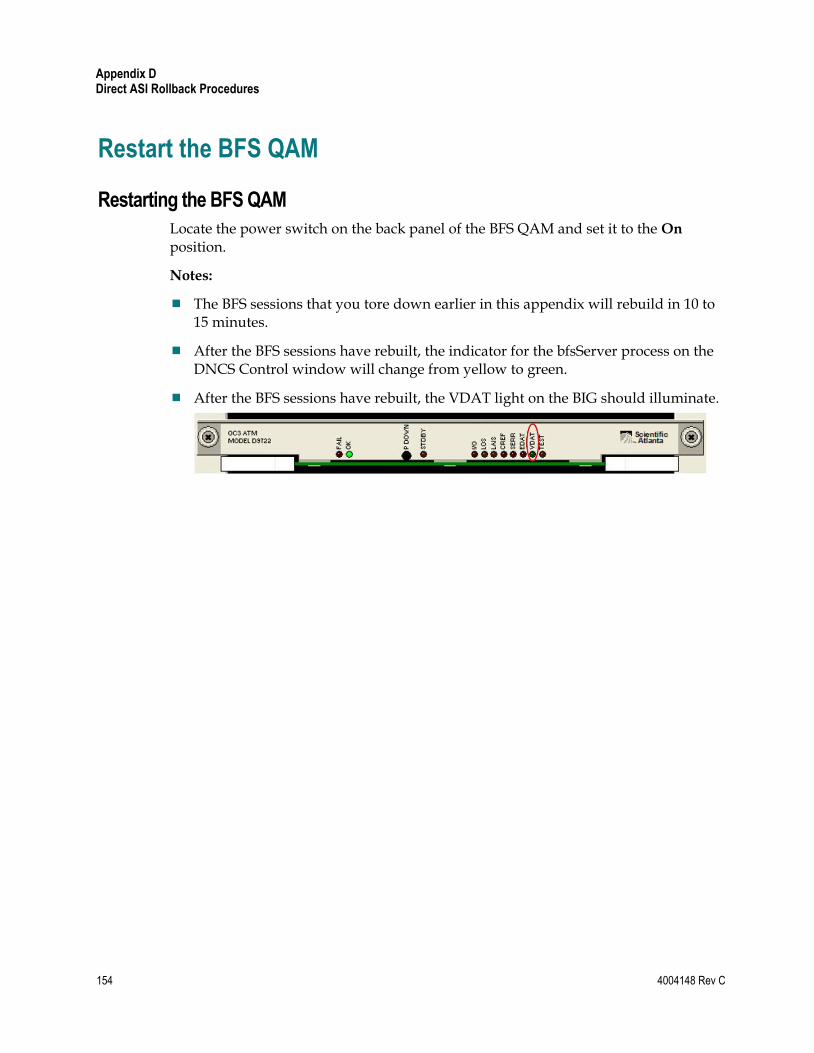
Appendix D Direct ASI Rollback Procedures
154 4004148 Rev C
Restart the BFS QAM
Restarting the BFS QAM
Locate the power switch on the back panel of the BFS QAM and set it to the On position.
Notes:
The BFS sessions that you tore down earlier in this appendix will rebuild in 10 to 15 minutes.
After the BFS sessions have rebuilt, the indicator for the bfsServer process on the DNCS Control window will change from yellow to green.
After the BFS sessions have rebuilt, the VDAT light on the BIG should illuminate.


Cisco Systems, Inc. 5030 Sugarloaf Parkway, Box 465447 Lawrenceville, GA 30042
678 277-1120 800 722-2009
www.cisco.com
This document includes various trademarks of Cisco Systems, Inc. Please see the Notices section of this document for a list of the Cisco Systems, Inc. trademarks used in this document. Product and service availability are subject to change without notice.
© 2007, 2012 Cisco and/or its affiliates. All rights reserved. June 2012 Printed in USA
Part Number 4004148 Rev C