SYSTEM OPERATOR TRANSMISSION - Eskom · When downloaded from the System Operator database, ... 15...
45
LJvR/Published 23.07.13 PUBLIC SYSTEM OPERATOR TRANSMISSION Ancillary Services Technical Requirements for 2014/15 – 2018/19 REV. 0 REF. NO.: 342-201
-
Upload
phungkhanh -
Category
Documents
-
view
218 -
download
0
Transcript of SYSTEM OPERATOR TRANSMISSION - Eskom · When downloaded from the System Operator database, ... 15...

LJvR/Published 23.07.13
PUBLIC
SYSTEM OPERATOR
TRANSMISSION
Ancillary Services Technical Requirements
for 2014/15 – 2018/19
REV. 0
REF. NO.: 342-201
ANCILLARY SERVICES TECHNICAL
REQUIREMENTS FOR 2013/14-2017/18
REFERENCE REV
342-201 0
PAGE 2 OF 45
PUBLIC When downloaded from the System Operator database, this document is uncontrolled and the responsibility rests
with the user to ensure it is in line with the authorised version on the database.
TABLE OF CONTENTS 1. INTRODUCTION ........................................................................................................................ 5
2. RESERVES ................................................................................................................................ 5
2.1. INTRODUCTION ................................................................................................................... 5
2.2. INSTANTANEOUS RESERVE ............................................................................................. 6
2.2.1. Description ...................................................................................... 6
2.2.2. Methodology .................................................................................... 6
2.2.3. Technical Requirements ................................................................. 6
2.3. REGULATING RESERVE ..................................................................................................... 7
2.3.1. Description ...................................................................................... 7
2.3.2. Methodology .................................................................................... 7
2.3.3. Technical Requirements ................................................................. 8
2.4. TEN MINUTE RESERVE .................................................................................................... 10
2.4.1. Description .................................................................................... 10
2.4.2. Methodology .................................................................................. 10
2.4.3. Technical Requirements ............................................................... 11
2.4.4. Calculation of Ten minute reserve for 2014 -2018 ...................... 12
2.5. SUPPLEMENTAL RESERVE ............................................................................................. 14
2.5.1. Description .................................................................................... 14
2.5.2. Methodology .................................................................................. 14
2.5.3. Technical requirements ................................................................ 14
2.6. EMERGENCY RESERVE ................................................................................................... 15
2.6.1. Description .................................................................................... 15
2.6.2. Methodology .................................................................................. 15
2.6.3. Technical requirements ................................................................ 15
2.7. RESERVE REQUIREMENTS SUMMARY .......................................................................... 16
3. BLACK START AND ISLANDING .......................................................................................... 16
3.1. BLACK START ......................................................................................................................... 16
3.1.1. Description .................................................................................... 16
3.1.2. Technical Requirements ............................................................... 17
3.1.3. Conclusions ................................................................................... 19

ANCILLARY SERVICES TECHNICAL
REQUIREMENTS FOR 2013/14-2017/18
REFERENCE REV
342-201 0
PAGE 3 OF 45
PUBLIC When downloaded from the System Operator database, this document is uncontrolled and the responsibility rests
with the user to ensure it is in line with the authorised version on the database.
3.2. UNIT ISLANDING ...................................................................................................................... 19
3.2.1. Description .................................................................................... 19
3.2.2. Technical Requirements .............................................................. 20
3.2.3. Conclusions ................................................................................... 21
4. REACTIVE POWER AND VOLTAGE CONTROL ................................................................... 21
4.1. DESCRIPTION ......................................................................................................................... 21
4.2. TECHNICAL REQUIREMENTS ................................................................................................... 22
4.3. CONCLUSIONS ....................................................................................................................... 25
5. CONSTRAINED GENERATION .............................................................................................. 26
5.1. INTRODUCTION ....................................................................................................................... 26
5.2. NATIONAL SYSTEM CONSTRAINTS ........................................................................................... 26
5.2.1. Cape Constraint ............................................................................ 27
5.3. SUPPORTING CLAUSES ................................................................................................... 27
5.3.1. Scope ............................................................................................. 27
5.3.2. Abbreviations and Definitions ..................................................... 28
5.3.3. Roles and Responsibilities ........................................................... 28
5.3.4. Monitoring Process ....................................................................... 29
6. APPENDIX A – SUPPLEMENTAL RESERVE DETERMINATION ......................................... 30
6.1. INTRODUCTION ....................................................................................................................... 30
6.2. METHODOLOGY FOR DERIVING EXPECTED USAGE OF DMP AND GAS ....................................... 30
6.3. SIMULATION STUDY ................................................................................................................ 30
6.3.1. Economic Level of Supplmental DMP ............................................. 30
6.4. CONCLUSIONS ....................................................................................................................... 33
7. APPENDIX B – CONSTRAINED GENERATION .................................................................... 34
7.1. CAPE CONSTRAINT ................................................................................................................ 34
7.2. REFERENCES .................................................................................................................... 45
ANCILLARY SERVICES TECHNICAL
REQUIREMENTS FOR 2013/14-2017/18
REFERENCE REV
342-201 0
PAGE 4 OF 45
PUBLIC When downloaded from the System Operator database, this document is uncontrolled and the responsibility rests
with the user to ensure it is in line with the authorised version on the database.
List of figures
Figure 1: CPS1 & Regulating up and down reserves vs. System Demand in April 2012 ...................... 8
Figure 2: CPS1 & Regulating up and down reserves vs. System Demand in June 2012 ...................... 9
Figure 3: Peak within Peak Profiles ..................................................................................................... 12
Figure 4: Ten-minute reserve calculation ............................................................................................. 12
Figure 5: Projection of intermittent renewable generation penetration ................................................. 13
Figure 6: cost saving versus DMP capacity .......................................................................................... 32
Figure 7: Representation of North of Hydra Corridor showing Measurement Points ........................... 34
Figure 8: Graphical representation of Western Grid Corridor showing Measurement Points .............. 35
Figure 9: Extract of Koeberg Production Plan (Rev 63) ....................................................................... 38
Figure 10: Expected 2014 OCGT Usage (Constrained & Unconstrained) ........................................... 40
Figure 11: Expected 2019 OCGT Usage (Constrained & Unconstrained) ........................................... 41
Figure 12: Expected 2018 OCGT Usage for Unplanned Reactor Trip ................................................. 42
Figure 13: Expected 2014 OCGTs Usage for Koeberg Trip during Refuel Period ............................... 43
Figure 14: Expected 2019 OCGTs Usage for Koeberg Trip during Refuel Period ............................... 44
List of tables
Table 1: Instantaneous reserve requirements ........................................................................................ 7
Table 2: Regulating up and down reserves requirements .................................................................... 10
Table 3: Ten minute reserve requirements ........................................................................................... 13
Table 4: Supplemental reserve requirements ....................................................................................... 14
Table 5: Emergency reserve requirements........................................................................................... 15
Table 6: Summary of Reserve Requirements....................................................................................... 16
Table 7: Energy and Peak Demand Forecast ...................................................................................... 37
ANCILLARY SERVICES TECHNICAL
REQUIREMENTS FOR 2013/14-2017/18
REFERENCE REV
342-201 0
PAGE 5 OF 45
PUBLIC When downloaded from the System Operator database, this document is uncontrolled and the responsibility rests
with the user to ensure it is in line with the authorised version on the database.
ANCILLARY SERVICES TECHNICAL REQUIREMENTS
FOR 2014/15 - 2018/19
1. INTRODUCTION
This document specifies the technical requirements for ancillary services for the
period 2014/15 till 2018/19. Its purpose is to make the technical requirements of the
System Operator for ancillary services known. The technical requirements as
specified in this document will be used to develop a medium term view of
requirements for ancillary services in the 5-year time horizon, and to contract for the
forthcoming financial year, 2014/15.
The following requirements are defined as ancillary services:
Reserves
Black Start
Islanding
Reactive Power Supply and Voltage Control
Constrained Generation
2. RESERVES
2.1. INTRODUCTION
The definitions of the five reserve categories included in ancillary services are given
in the Eskom Short Term Energy Reserve Procedure SPC 46-2 and the South
African Grid Code [3]. The minimum requirement for each reserve category is
revised annually. Each reserve category has its own required level and is exclusive,
that is, capacity reserved for one category cannot be used for another category.
National Control will dispatch reserves according to the scheduling rules as far as

ANCILLARY SERVICES TECHNICAL
REQUIREMENTS FOR 2013/14-2017/18
REFERENCE REV
342-201 0
PAGE 6 OF 45
PUBLIC When downloaded from the System Operator database, this document is uncontrolled and the responsibility rests
with the user to ensure it is in line with the authorised version on the database.
possible while adhering to Eskom procedure 342-141, “Control of System
Frequency under Normal and Abnormal Conditions”.
2.2. INSTANTANEOUS RESERVE
2.2.1. Description
The instantaneous reserve is the generating capacity or demand side managed load
fully available within ten seconds to arrest the frequency outside the frequency
deadband. The reserve response must be sustained for at least 10 minutes. It is
needed to arrest the frequency at an acceptable level following a contingency, such
as a generator trip, or a sudden surge in load. Generators are also expected to
respond to high frequencies (above 50.15 Hz). The requirements are given in the
South African Network Grid Code.
2.2.2. Methodology
The requirement is to keep frequency above 49.5 Hz following all credible single
contingencies from a frequency within the deadband limit of 50±0.15 Hz. The
credible single contingency is the loss of the largest unit. The credible multiple
contingency is the loss of three typical coal fired units. The effect of rotating loads
on system frequency was considered in the study.
2.2.3. Technical Requirements
There is no current technical requirement for Instantaneous down reserve capacity.
However this service is mandatory for all generators according to the South African
Network Grid Code, especially if the frequency exceeds 50.5 Hz.
The Instantaneous up reserve requirement was determined using DigSilent, by
establishing the effect of governing on system frequency [15]. The study tested
various scenarios including various amounts of generation and demand side
governing capacity. The study results indicated that more demand side capacity is

ANCILLARY SERVICES TECHNICAL
REQUIREMENTS FOR 2013/14-2017/18
REFERENCE REV
342-201 0
PAGE 7 OF 45
PUBLIC When downloaded from the System Operator database, this document is uncontrolled and the responsibility rests
with the user to ensure it is in line with the authorised version on the database.
needed to replace the equivalent generation capacity. The results are shown in
Table 1.
Table 1: Instantaneous reserve requirements
This shows that a total instantaneous reserve of 600 MW during peak periods and
700 MW during off peak periods is required for the review period. These
requirements are based on only generators providing all the instantaneous reserve.
2.3. REGULATING RESERVE
2.3.1. Description
Regulating reserve is generating capacity or demand side managed load that is
available to respond within 10 seconds and is fully activated within 10 minutes. The
purpose of this reserve is to make enough capacity available to maintain the
frequency close to scheduled frequency and keep tie line flows within schedule.
2.3.2. Methodology
The regulating up and down requirement is based on meeting the following:
i. Control Performance Standard (CPS1) performance criterion and SAPP
requirement (i.e. keep frequency within dead band for 95% of the time)
ii. Cater for a trip of an average unit MW size on the IPS of stations with capacity
>3000MW
Period 2014/15
MW
2015/16
MW
2016/17
MW
2017/18
MW
2018/19
MW Peak 600 600 600 600 600
Off Peak 700 700 700 700 700

ANCILLARY SERVICES TECHNICAL
REQUIREMENTS FOR 2013/14-2017/18
REFERENCE REV
342-201 0
PAGE 8 OF 45
PUBLIC When downloaded from the System Operator database, this document is uncontrolled and the responsibility rests
with the user to ensure it is in line with the authorised version on the database.
2.3.3. Technical Requirements
The IPS needs sufficient regulating range up and down every hour of the day to keep
the frequency and tie lines within acceptable limits, while meeting the peak load
within the peak hour.
A) CPS1 performance criterion and SAPP requirement
A control area is required to carry enough regulating reserve so that AGC operates
effectively and the control area satisfies the SAPP CPS requirements. CPS1 is a
statistical measure of variability of the ACE of a control area, measuring the ACE in
combination with the frequency error of the interconnection for a control area. It
measures whether a control area’s control action helps or hurts the power system
i.e. during low frequencies, it checks whether a control area increases generation to
restore system frequency. During high frequencies, it checks whether a control area
decreases generation to restore system frequency. To meet the CPS standard, a
control area must meet CPS1 most of the time. Assuming the system frequency
performance remained as observed in 2012, the optimal regulating up and down
reserves to meet CPS1 were determined.
Figure 1: CPS1 & Regulating up and down reserves vs. System Demand in April 2012

ANCILLARY SERVICES TECHNICAL
REQUIREMENTS FOR 2013/14-2017/18
REFERENCE REV
342-201 0
PAGE 9 OF 45
PUBLIC When downloaded from the System Operator database, this document is uncontrolled and the responsibility rests
with the user to ensure it is in line with the authorised version on the database.
Figure 1 shows that CPS1 exceeds 100% when regulating up and down reserves
are each at least 500 MW.
Figure 2: CPS1 & Regulating up and down reserves vs. System Demand in June 2012
Figure 2 shows that regulating up and down reserves should be at least 550 MW to
meet CPS1. AGC performance analysis is considered between 09:00 and 17:00
when system load changes slowly. The system load during hours outside 09:00 and
17:00 changes rapidly, requiring manual intervention from controllers.
B) Trip of an average unit MW size for stations with capacity greater than
3000MW
The average unit MW size of the coal fired units for stations with a total capacity of
more than 3000MW is 600 MW. The higher of the requirements in A) and B) is
600 MW. Therefore 600 MW regulating up and 600 MW regulating down capacity is
required.

ANCILLARY SERVICES TECHNICAL
REQUIREMENTS FOR 2013/14-2017/18
REFERENCE REV
342-201 0
PAGE 10 OF 45
PUBLIC When downloaded from the System Operator database, this document is uncontrolled and the responsibility rests
with the user to ensure it is in line with the authorised version on the database.
Table 2: Regulating up and down reserves requirements
Reserve Period 2014/15
MW
2015/16
MW
2016/17
MW
2017/18
MW
2018/19
MW Regulating
up
Peak 600 600 600 600 600
Off Peak 600 600 600 600 600
Regulating
down
Peak 600 600 600 600 600
Off Peak 600 600 600 600 600
2.4. TEN MINUTE RESERVE
2.4.1. Description
Ten minute reserve is generating capacity or demand side managed load that can
respond within 10 minutes when called upon. It may consist of offline quick start
generating plant (e.g. hydro or pumped storage) or demand side capacity that can be
committed within 10 minutes. The purpose of this reserve is to restore Instantaneous
and Regulating reserve to the required levels after an incident. The Ten minute
reserve is bid in day-ahead into the reserve market. Ten minute reserve may also be
used for localised voltage stability and capacity constraints. Ancillary Services
requires resources which may be used up to 600 hours per year (assuming a usage
over 50 weeks, 4 days and 3 peak hours per day) for the Ten minute market. In
addition, if the cost of any potential Ten minute reserve resource is close to or
higher than gas turbines, it must be used in the emergency reserve market. Any new
Ten minute reserve resource must have no onerous energy restrictions since this
reserve may be required to be used nearly every day.
2.4.2. Methodology
The total requirement is based on carrying sufficient Ten minute reserve to ensure
that:
i. The total operating reserve can replace a credible multiple unit trip
ii. The total operating reserve meets SAPP operating reserve requirements

ANCILLARY SERVICES TECHNICAL
REQUIREMENTS FOR 2013/14-2017/18
REFERENCE REV
342-201 0
PAGE 11 OF 45
PUBLIC When downloaded from the System Operator database, this document is uncontrolled and the responsibility rests
with the user to ensure it is in line with the authorised version on the database.
iii. The total regulating (in one direction) plus Ten minute reserve cater for typical
peak within peak load variations
The requirement is the greater of the three criteria.
2.4.3. Technical Requirements
A) Multiple unit trip requirement
A credible multiple unit trip is defined in the grid code as a typical trip of three coal
fired units. To ensure reliability it was assumed that the total operating reserve
should be sufficient to replace the loss of three biggest coal fired units. Thus, up to
2014 Majuba has the biggest three units at 3 x 669 = 2007 MW and from 2015
Medupi will have the biggest three coal fired units at 3 x 722 = 2166 MW. The Ten
minute reserve requirement = Total operating – instantaneous – regulating
B) SAPP Requirement
The proposed SAPP Operating Guidelines state that a minimum of 1070 MW of
operating reserve is currently required from the Eskom control area and half of this
must be spinning reserve. The Ten minute reserve requirement = Total operating –
instantaneous – regulating
C) Peak within peak study
The peak within peak is defined as the difference between the absolute peak and the
average demand for the hour. Peak within peak values were calculated for typical
weeks in summer and winter.

ANCILLARY SERVICES TECHNICAL
REQUIREMENTS FOR 2013/14-2017/18
REFERENCE REV
342-201 0
PAGE 12 OF 45
PUBLIC When downloaded from the System Operator database, this document is uncontrolled and the responsibility rests
with the user to ensure it is in line with the authorised version on the database.
Figure 3: Peak within Peak Profiles
Figure 3 is based on typical weeks for May 2012 to April 2013 months. Thus, peak
within peak value = 1400 MW. Average value was chosen to have a representative
value. The difference between the absolute peak and the average is minimal.
2.4.4. Calculation of Ten minute reserve for 2014 -2018
The Ten minute requirement was evaluated using the following equation:
Ten minute requirement = maximum(MUT capacity - IR - RR, SAPP requirement - IR
- RR, Pk_in_Pk – RR), where MUT is a multiple unit trip, IR is the instantaneous
reserve, RR is the regulating reserve and Pk_in_Pk is the peak within the peak. The
results are summarised as follows:
Figure 4: Ten-minute reserve calculation

ANCILLARY SERVICES TECHNICAL
REQUIREMENTS FOR 2013/14-2017/18
REFERENCE REV
342-201 0
PAGE 13 OF 45
PUBLIC When downloaded from the System Operator database, this document is uncontrolled and the responsibility rests
with the user to ensure it is in line with the authorised version on the database.
The Ten minute reserve requirements are shown in Table 3 below.
Table 3: Ten minute reserve requirements
Period 2014/15
MW
2015/16
MW
2016/17
MW
2017/18
MW
2018/19
MW
Peak 800 1000 1000 1000 1000
Off Peak 700 900 900 900 900
Literature shows that impact of intermittent generation is significant on frequency
control above 15% penetration levels. Since intermittent generation penetration is
less than 10% by 2018, no significant impact is expected on operating reserve. Thus,
the above stated operating reserves requirements should be sufficient to counter the
effect of renewables on frequency control. See Figure 5 below:
Figure 5: Projection of intermittent renewable generation penetration

ANCILLARY SERVICES TECHNICAL
REQUIREMENTS FOR 2013/14-2017/18
REFERENCE REV
342-201 0
PAGE 14 OF 45
PUBLIC When downloaded from the System Operator database, this document is uncontrolled and the responsibility rests
with the user to ensure it is in line with the authorised version on the database.
2.5. SUPPLEMENTAL RESERVE
2.5.1. Description
Supplemental reserve is generating or demand side capacity that can respond in 6
hours to restore the other reserves. This reserve must be available for at least 2
hours (See SPC 46-2).
2.5.2. Methodology
The total requirement is based on carrying sufficient supplemental capacity to avoid
running gas turbines.
2.5.3. Technical requirements
It costs money to provide DMP supplemental reserve. Given the current expected
amount of various emergency reserves that are (or should be) dispatched before
DMP based on cost such as EL1 and Interruptible load, the economic amount of
DMP capacity may be calculated. This will depend on the relative energy costs of
DMP compared to gas turbines, as well as the capacity charge paid to customers for
making their capacity available to be reduced when the need arises. If gas is
cheaper than DMP at any time then no DMP should be utilised before using gas
turbines (including OCGT). The details of the study are given in Appendix A –
Supplemental Reserve Determination. The result of the study is that 1100 MW of
supplemental DMP is required. The supplemental reserve requirements are as
follows:
Table 4: Supplemental reserve requirements
Period 2014/15
MW
2015/16
MW
2016/17
MW
2017/18
MW
2018/19
MW
Peak/ Off peak 1100 1100 1100 1100 1100

ANCILLARY SERVICES TECHNICAL
REQUIREMENTS FOR 2013/14-2017/18
REFERENCE REV
342-201 0
PAGE 15 OF 45
PUBLIC When downloaded from the System Operator database, this document is uncontrolled and the responsibility rests
with the user to ensure it is in line with the authorised version on the database.
2.6. EMERGENCY RESERVE
2.6.1. Description
Emergency reserve is capacity that is required less often than Ten minute reserve.
This includes interruptible loads, generator emergency capacity (EL1), and gas
turbine capacity. The call up time depends on the technology but a maximum call up
of 10 minutes is preferred. Emergency reserve are utilised in accordance with
SOPC0008. The reserve must also be under the direct control of the control room at
National Control. These requirements arise from the need to take quick action when
any abnormality arises on the system.
2.6.2. Methodology
The total requirement is based on (operating plus supplemental plus emergency)
reserves capacity equal to largest power station capacity. Therefore emergency
reserve = largest power station capacity – operating reserve - supplemental reserve.
2.6.3. Technical requirements
The worst contingency catered for in deriving the technical requirements is the loss
of the largest power station, which should be replaced by operating, supplemental
and emergency reserve capacity. Majuba is the largest power station from 2014/15
till 2016/17 with a total capacity of 3843 MW. From 2017/18 Medupi will be the new
largest power station with a total capacity of 4332 MW according to the integrated
resource plan 2010. The emergency reserve requirements are as follows:
Table 5: Emergency reserve requirements
Period 2014/15
MW
2015/16
MW
2016/17
MW
2017/18
MW
2018/19
MW
Peak/ Off peak 800 600 600 1100 1100

ANCILLARY SERVICES TECHNICAL
REQUIREMENTS FOR 2013/14-2017/18
REFERENCE REV
342-201 0
PAGE 16 OF 45
PUBLIC When downloaded from the System Operator database, this document is uncontrolled and the responsibility rests
with the user to ensure it is in line with the authorised version on the database.
2.7. RESERVE REQUIREMENTS SUMMARY
Table 6 shows the expected requirements for each reserve category from 2014/15 till
2018/19.
Table 6: Summary of Reserve Requirements
Reserve Time of Use
Period
2014/15
MW
2015/16
MW
2016/17
MW
2017/18
MW
2018/19
MW
Instantaneous Peak 600 600 600 600 600
Off Peak 700 700 700 700 700
Regulating Peak 600 600 600 600 600
Off Peak 600 600 600 600 600
Ten Minute Peak 800 1000 1000 1000 1000
Off Peak 700 900 900 900 900
Operating All periods 2000 2200 2200 2200 2200
Supplemental All periods 1100 1100 1100 1100 1100
Emergency All periods 800 600 600 1100 1100
Total All periods 3900 3900 3900 4400 4400
3. BLACK START AND ISLANDING
Black start and unit islanding services are required for restoring the network in the
event of a blackout or an incident on the system.
3.1. BLACK START
3.1.1. Description
System black start capability is the provision of generating equipment that, following
a system black out, is able:
To start itself without an outside electrical supply (self-start), and

ANCILLARY SERVICES TECHNICAL
REQUIREMENTS FOR 2013/14-2017/18
REFERENCE REV
342-201 0
PAGE 17 OF 45
PUBLIC When downloaded from the System Operator database, this document is uncontrolled and the responsibility rests
with the user to ensure it is in line with the authorised version on the database.
To energise a defined portion of the transmission system so that it can act as
a start-up supply for other base load generators to be synchronised as part of
a process of power system restoration.
3.1.2. Technical Requirements
The technical requirements for Black-start involve those stated in the South African
Grid Code (SAGC) and also the minimum System Operator requirements.
A) South African Grid Code (SAGC) Requirements
1) The SAGC requires that there be at least two suitable Black-start facilities at
different locations in the system.
2) The System Operator shall determine the mimimum requirements for each of the
Black-start facility mentioned above before contracting.
3) To prove the capability of the system, the System Operator shall perform partial
and full black start tests periodically (every 3 & 6 years) as required by the SAGC.
This shall be done in accordance with the latest version of the operating standard
EST 32-1190.
A partial test done every three years shall involve:
Isolation of the unit
Starting up of the unit from an independent source and
Energising a defined portion of the transmission / distribution system.
A full test done every six years shall involve:
Isolation of the unit
Starting up of the unit from an independent source
Energising a defined portion of the transmission / distribution system and
The subsequent loading of the unit to prove blackstart capability.

ANCILLARY SERVICES TECHNICAL
REQUIREMENTS FOR 2013/14-2017/18
REFERENCE REV
342-201 0
PAGE 18 OF 45
PUBLIC When downloaded from the System Operator database, this document is uncontrolled and the responsibility rests
with the user to ensure it is in line with the authorised version on the database.
4) Due diligence and as part of preparations, planning and studies are done prior to
the partial or full Black start facility test.
5) A thermal power station shall be capable of self-starting at least one unit after a
forced shut down without support from the external grid.
6) The first unit shall be capable of energising a portion of the power system within
four hours of shutdown.
B) Technical Requirements For Black Start Facilities
1) Each black start facility shall be available at least 90% of the year as long as
maintenance and repairs are coordinated such that there is at least one
facility available all the time.
2) Geographical location of a unit capable of black starting has to allow for
restoration without technical constraints.
3) The station shall conduct periodic diesel generator compliance monitoring
tests as required by the System Operator. These tests include testing the self-
start facility and monitoring fuel and water levels.
Periodic self-start tests involve;
Full Speed No Load [FSNL] – run machine once a week for 2 hours
Full Speed Base Load [FSBL] – run machine once a month for 3 hours
o The tests are done to “heat soak” the machines, so reducing the
risk of rotor and stator misalignment of the diesel generator.
4) There shall have sufficient water/fuel for three black start attempts on the unit
at all times.
5) Units contracted for black start shall be capable of providing sufficient reactive
power support to control the declared transmission voltages between ±5% of
nominal voltage.
6) The unit shall be capable of picking up load blocks of 30 to 50 MW.

ANCILLARY SERVICES TECHNICAL
REQUIREMENTS FOR 2013/14-2017/18
REFERENCE REV
342-201 0
PAGE 19 OF 45
PUBLIC When downloaded from the System Operator database, this document is uncontrolled and the responsibility rests
with the user to ensure it is in line with the authorised version on the database.
7) The Black-start facility shall be capable of maintaining the frequency within 49
to 51 Hz during energisation and load pick up.
8) Due to the fact that system failures can occur during restoration, the power
station shall be capable of sequentially black starting a unit up to 3 times.
C) Additional Requirements For Pump Storage or Hydro Black Start Facility
A pumped storage/ hydro station shall be capable of self-starting one or more
units, energising a part of the grid (line to a thermal station) and so providing
auxiliary power to enable a thermal unit to start within four hours of shutdown of
the thermal unit
3.1.3. Conclusions
The SAGC requires that Eskom shall at least have two Black-start facilities at
different locations and furthermore instructs the System Operator to determine
the minimum requirements for those facilities before contracting.
To improve reliability and speed up the restoration plan during a blackout, the
System Operator opted for a third Black-start facility with the first unit, June
2014 set as the commissioning date.
The system restoration plan review involving further system studies to
determine the impact of a third Black-start facility, identification and testing of
synchronising points to support the technical requirements and improve the
system reliability.
3.2. UNIT ISLANDING
3.2.1. Description
Unit islanding refers to the capability of a generating unit to disconnect from the
transmission system by opening the HV breaker, and to automatically control its
auxiliaries to maintain stability of the turbo generator, and to supply its auxiliary load

ANCILLARY SERVICES TECHNICAL
REQUIREMENTS FOR 2013/14-2017/18
REFERENCE REV
342-201 0
PAGE 20 OF 45
PUBLIC When downloaded from the System Operator database, this document is uncontrolled and the responsibility rests
with the user to ensure it is in line with the authorised version on the database.
without external supply. The unit shall be capable of islanding from full load and
remaining in an islanded state for at least two hours.
3.2.2. Technical Requirements
Unit islanding is a mandatory ancillary service for generating units certified for
islanding. To prove the capability of the station to be certified, the South African Grid
Code (Network Code, Appendix A2.3.8) (SAGC) requires a once off test to be
performed.
A) South African Grid Code (SAGC) Requirements
1) Units that do not have a black start facility or self start capability shall island
when required except if construction occurred before the implementation of
the Grid Code and without an HP bypass facility designed for islanding. Thus
all the units commissioned after the SAGC should have Islanding capabilities.
2) Return to service units are currently exempted from this requirement as they
do not have an HP bypass facility required for islanding.
3) The SAGC specifies that only units rating greater than 200 MVA will be
certified.
4) The units are expected to disconnect from the power system at full load and
sustain the islanding for two hours.
5) The prototype test is only done on a representative unit for the station with
routine testing being required for all remaining units.
a) The once off prototype test requires the unit be islanded from full output
and remain in an islanded state for a minimum of two hours.
b) Routine tests shall be performed on each unit after each general overhaul
or six years. Routine tests require a unit to island from 60% of MCR and
remain there for 20 minutes, under normal operating conditions.
6) The tests shall be carried out in accordance with the latest version of
procedure EPC 32-951, “Certification/ Decertification Procedure for Turbo-

ANCILLARY SERVICES TECHNICAL
REQUIREMENTS FOR 2013/14-2017/18
REFERENCE REV
342-201 0
PAGE 21 OF 45
PUBLIC When downloaded from the System Operator database, this document is uncontrolled and the responsibility rests
with the user to ensure it is in line with the authorised version on the database.
Generator Unit Islanding” and “Standard for Steam Turbine Unit Islanding,
Load Rejection and Speed Control Verification” (GGS 0500).
3.2.3. Conclusions
Studies under the restoration plan review will be conducted to determine the
optimum placement of islanding including determining exactly how many units are
expected to island during a system Blackout. The requirements derived from the
study results are expected to speed up the restoration plan and thereby improve
system reliability.
4. REACTIVE POWER AND VOLTAGE CONTROL
4.1. DESCRIPTION
Reactive power supply and voltage control form part of the ancillary services
required by the System Operator to efficiently perform its main function of supplying
electrical power while maintaining the required levels of supply quality and security.
Voltage control involves control of reactive power to maintain acceptable voltages
under normal and contingency conditions. Voltage is maintained within fairly tight
range to protect the Customer and Utility equipment and prevent voltage collapse.
Shunt caps, reactors and transformer tap changers are used on the Transmission
system but they are slow to respond. FACTS devices do not produce voltage but
can control reactive power. Synchronous generators can provide dynamic reactive
power support to voltage control as quickly as possible.
ANCILLARY SERVICES TECHNICAL
REQUIREMENTS FOR 2013/14-2017/18
REFERENCE REV
342-201 0
PAGE 22 OF 45
PUBLIC When downloaded from the System Operator database, this document is uncontrolled and the responsibility rests
with the user to ensure it is in line with the authorised version on the database.
4.2. TECHNICAL REQUIREMENTS
The technical requirements for reactive power and voltage control involve
requirements from the System Operator, South African Grid Code (SAGC) and
Renewables Grid Code.

ANCILLARY SERVICES TECHNICAL
REQUIREMENTS FOR 2013/14-2017/18
REFERENCE REV
342-201 0
PAGE 23 OF 45
PUBLIC When downloaded from the System Operator database, this document is uncontrolled and the responsibility rests
with the user to ensure it is in line with the authorised version on the database.
A) System Operator (SO) Requirements
1) SO shall use peaking stations (pump storage and OCGTs) in SCO for voltage
control.
2) All installed thermal and peaking stations will be used for voltage control at the
discretion of the SO.
3) All generators shall have automatic voltage regulators (AVR)/converters in an
automatic voltage control mode.
4) All generators shall inform/update SO of any restriction that might affect the
reactive power support.
All generators capable of voltage control shall be required to do reactive capability
tests as stipulated in Eskom procedure 32-728, “Generating unit reactive power and
voltage control certification procedure”.
B) SAGC Requirements for Renewables Including IPPs
1) As required by the South African Grid Code, Network Code, all units greater
than 100 MW shall be capable of supplying rated power output (MW) at any
point between the limits of 0.85 power factor lagging and 0.95 power factor
leading at the HV side of the generator transformer.
2) Reactive power output shall be fully variable between these limits under AVR,
manual or other controls.
3) SO shall control power station export/import of reactive power through
TEMSE or telephone.
4) When a unit is in pumping or generating, reactive power supply is mandatory
in full operating range
5) Voltages shall not deviate by more than ±5% from declared voltages under
normal operating conditions.
6) Gas Turbines units build after the implementation of a Grid Code shall be
capable of operating in SCO.

ANCILLARY SERVICES TECHNICAL
REQUIREMENTS FOR 2013/14-2017/18
REFERENCE REV
342-201 0
PAGE 24 OF 45
PUBLIC When downloaded from the System Operator database, this document is uncontrolled and the responsibility rests
with the user to ensure it is in line with the authorised version on the database.
7) Generators shall conduct prototype and routine tests to demonstrate reactive
capability.
All units built after the implementation of the South African Grid Code shall be
equipped with power system stabilisers as defined in IEC 60034, IEEE42. Reactive
output shall be fully variable so as to achieve acceptable levels of voltage (± 5%)
under automatic or manual control.
C) SAGC Requirements for Renewables/IPPs
1) During start up / energising, the Renewables/IPPs are only allowed to
consume or export reactive power from the transmission system by not more
that 5% of rated reactive power.
2) Different power factor gategories are specified as follows;
Category A: The IPP shall comply with a power factor range of 0.95
lagging < PF < 1.0 when generating more than 20% of rated power.
Category B: The IPP shall be designed so that the operating point can lie
anywhere within 0.975 lagging and 0.975 leading.
Category C: The IPP shall be designed so that the operating point can lie
anywhere within the 0.95 leading and 0.95 lagging.
3) The Renewables/IPP shall be equipped with reactive power control functions
capable of controlling the reactive power supplied by the IPP at the point of
connection (POC) as well as a voltage control function capable of controlling
the voltage at the POC via orders using set points.
4) The Renewables/IPPs shall ensure that they can function/operate under any
of the three different modes mentioned below. Furthermore the reactive power
ANCILLARY SERVICES TECHNICAL
REQUIREMENTS FOR 2013/14-2017/18
REFERENCE REV
342-201 0
PAGE 25 OF 45
PUBLIC When downloaded from the System Operator database, this document is uncontrolled and the responsibility rests
with the user to ensure it is in line with the authorised version on the database.
and voltage control functions are mutually exclusive, which means that only
one of the three functions mentioned below can be activated at a time:
a) Q-control
b) Power Factor–control
c) Voltage-control
5) The applied parameter settings for reactive power and voltage control
functions shall be determined before commissioning by the NSP in
collaboration with the SO.
4.3. CONCLUSIONS
The technical requirements for reactive power and voltage control were
enhanced to accommodate all the new Suppliers (Renewables/IPPs) connected
to the transmission system taking into consideration that the service is mandatory
for all the role players.
Although Eskom has different generator power factor requirements for
conventional plants and Renewables/IPPs it is expected that this will not affect
the desired voltage profile during operations as long as all the generators adhere
to the System Operator instructions.
The reactive power contribution of conventional plants and Renewables/IPP
plants is very dependent on the technology used, the connection point and
voltage level as well as additional reactive power support (SVC, STATCOM).
Furthermore, the integration of Renewables/IPPs further increases complexity
and challenges to the existing protection and automation at all voltage levels
within the Eskom network system.

ANCILLARY SERVICES TECHNICAL
REQUIREMENTS FOR 2013/14-2017/18
REFERENCE REV
342-201 0
PAGE 26 OF 45
PUBLIC When downloaded from the System Operator database, this document is uncontrolled and the responsibility rests
with the user to ensure it is in line with the authorised version on the database.
5. CONSTRAINED GENERATION
5.1. INTRODUCTION
The Grid Code [3] requires that the System Operator manage real-time system
constraints within safe operating limits, using constrained generation as one of the
ancillary services as required. In particularly, it requires multiple outages of a
credible nature to be studied to ensure that the operation of the system protects
against cascading outages for such an event, wherever practical. To support the
MYPD, this requires the System Operator to identify national system constraints over
a 5 year horizon, define relevant system problems by establishing those constraints
affecting the capacity to meet demand, and draw conclusions on the need for this
service. An input in establishing the need for this service includes determining the
constraints with a duration beyond a few hours that have a significant impact and
have a high probability. This requirement excludes the long duration planned
transmission outages that are coincident with full generation at Matimba from the list
of national constraints requiring constrained generation, for example, as such
planned outage can be coordinated with Matimba generation outages.
5.2. NATIONAL SYSTEM CONSTRAINTS
The Grid Code requires that those power stations which run out of schedule as part
of constrained generation must be financially compensated. The power corridor
down to the Cape represents the only transmission network where there is a risk of
running expensive gas generation out of the economic merit order, constituting
constrained generation for the system.
Only with commissioning of the second unit at Medupi Power Station is the station
expected to have to be constrained down under light loading in the region. This will
represent uneconomic dispatch of generation for the system and will be counted as
part of constrained generation. Once the Operations Planning Department has

ANCILLARY SERVICES TECHNICAL
REQUIREMENTS FOR 2013/14-2017/18
REFERENCE REV
342-201 0
PAGE 27 OF 45
PUBLIC When downloaded from the System Operator database, this document is uncontrolled and the responsibility rests
with the user to ensure it is in line with the authorised version on the database.
established how much spinning is needed, the extent of the problem for constrained
generation can be established. [4]
5.2.1. Cape Constraint
The 765 kV strengthening is now expected to be commissioned up to Kappa
substation by July 2014, delayed by a further 10 months over that previously
assumed [6]. Based on the assumed regional and national demand, generation
performance and cost, 14.2 GWh is required from the OCGT for constrained
generation to cater for the N-2 refuel contingency at the start of the 2014/15 financial
year.
To limit the need for use of expensive local generation, Koeberg is restricted to refuel
outside of winter (01 May to 31 August). This restriction on Koeberg, requires that it
replace some of its partially spent fuel with new fuel, incurring a financial loss due to
the Cape network constraint. Koeberg is compensated financially for this.
The 765 kV Cape transmission is expected to reach Kappa substation by July 2014,
increasing the Western Grid transfer limits. Once the 765 kV Cape transmission
strengthening is integrated at 400 kV, there is no constrained generation requirement
for the Cape based on the projected regional demand. The motivation for this
requirement is given in Appendix B – Constrained Generation.
5.3. SUPPORTING CLAUSES
5.3.1. Scope
This document specifies the technical requirements for ancillary services for financial
years 2014/15 to 2018/19.
The purpose of the document is to make the System Operator’s requirements known
to ensure a reliable network and provide optimal usage of ancillary services for the

ANCILLARY SERVICES TECHNICAL
REQUIREMENTS FOR 2013/14-2017/18
REFERENCE REV
342-201 0
PAGE 28 OF 45
PUBLIC When downloaded from the System Operator database, this document is uncontrolled and the responsibility rests
with the user to ensure it is in line with the authorised version on the database.
next five financial years. It applies to all Eskom line divisions, Transmission,
Distribution, Customer Services and Generation.
All participants of ancillary services need to meet all aspects of the South African
Grid Code relating to these services.
5.3.2. Abbreviations and Definitions
GX: Generation division
IPS: Interconnected Power System
Peak and Off-peak: Peak periods are considered only during weekdays. There are
two peak periods in the daily system load profile, morning peak and evening peak,
occuring at different times of the day during winter and summer months. Public
holidays are treated the same as weekends with no peak periods. In winter,
identified as May to August, the morning peak occurs from 06:00 to 09:00 and the
evening peak occurs from 17:00 to 20:00. In summer, covering the remainder of the
year outside winter, the morning peak occurs from 09:00 to 12:00 and the evening
peak from 18:00 to 21:00. Thus the peak periods occur for six hours of the day every
weekday.
OP: Operating Procedure
OS: Operating Standard
SO: System Operator
SOG: System Operator Guideline
5.3.3. Roles and Responsibilities
The personnel from Ancillary Services in the System Operator business area, in
consultation with the relevant service providers of Ancillary Services, are responsible
for providing the detailed technical requirements. The General Manager, System
Operator signs approval of these requirements.

ANCILLARY SERVICES TECHNICAL
REQUIREMENTS FOR 2013/14-2017/18
REFERENCE REV
342-201 0
PAGE 29 OF 45
PUBLIC When downloaded from the System Operator database, this document is uncontrolled and the responsibility rests
with the user to ensure it is in line with the authorised version on the database.
5.3.4. Monitoring Process
The provision of these requirements is monitored regularly via the monthly
performance reports.

ANCILLARY SERVICES TECHNICAL
REQUIREMENTS FOR 2013/14-2017/18
REFERENCE REV
342-201 0
PAGE 30 OF 45
PUBLIC When downloaded from the System Operator database, this document is uncontrolled and the responsibility rests with the
user to ensure it is in line with the authorised version on the database.
6. APPENDIX A – SUPPLEMENTAL RESERVE DETERMINATION
6.1. INTRODUCTION
The method used for this study is to simulate the hourly commitment and dispatch for
calendar year 2014 using the PLEXOS production simulation program. This gives the
expected usage of emergency resources and supplemental DMP. The reason the two
reserve categories are handled together is because supplemental DMP is part of the
emergency resource merit order followed by National Control during plant shortages.
6.2. METHODOLOGY FOR DERIVING EXPECTED USAGE OF
DMP AND GAS
The method used for this study is to simulate the hourly commitment and dispatch for
calendar year 2014 using the PLEXOS production simulation program. This gives the
expected usage of emergency resources and supplemental DMP. The reason the two
reserve categories are handled together is because supplemental DMP is part of the
emergency resource merit order followed by National Control during plant shortages.
6.3. SIMULATION STUDY
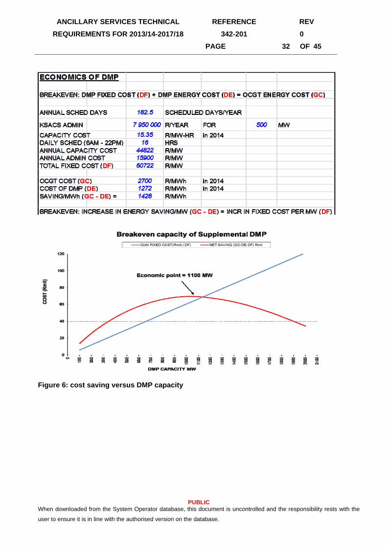
6.3.1. Economic Level of Supplmental DMP
The breakeven level of supplemental DMP capacity was determined by comparing the total cost of
each extra MW of capacity of DMP with the saving due to running one less MW of gas.
The cost drivers for DMP are fixed and variable costs. The fixed cost is incurred over the year and
consists of:
(i) Administration costs paid to the DMP customer data aggregator. These are assumed to scale
linearly with the capacity certified for DMP, as each resource needs metering, monitoring and
payment administration.
(ii) Capacity payment to the customers. The customers are paid for every hour that they are
scheduled by National control. Thus, the payment is proportional to the capacity bid available each
day, since currently all the capacity is scheduled by National Control whenever the day-ahead

ANCILLARY SERVICES TECHNICAL
REQUIREMENTS FOR 2013/14-2017/18
REFERENCE REV
342-201 0
PAGE 31 OF 45
PUBLIC When downloaded from the System Operator database, this document is uncontrolled and the responsibility rests with the
user to ensure it is in line with the authorised version on the database.
reserve falls below the target limit. Historical data shows that the number of days scheduled are
nearly 50% of all days in a year.
(iii) The variable payment for usage is the energy price for DMP times the energy reduced.
ANCILLARY SERVICES TECHNICAL
REQUIREMENTS FOR 2013/14-2017/18
REFERENCE REV
342-201 0
PAGE 32 OF 45
PUBLIC When downloaded from the System Operator database, this document is uncontrolled and the responsibility rests with the
user to ensure it is in line with the authorised version on the database.
Figure 6: cost saving versus DMP capacity

ANCILLARY SERVICES TECHNICAL
REQUIREMENTS FOR 2013/14-2017/18
REFERENCE REV
342-201 0
PAGE 33 OF 45
PUBLIC When downloaded from the System Operator database, this document is uncontrolled and the responsibility rests with the
user to ensure it is in line with the authorised version on the database.
FINAL RUN - 20 STEPS OF 100 MW
CUM ENERGY COST
SAVING (GC-DE) Rmil
1 100 100 13.9 139 6 18 24 20 13.82 100 200 12.7 127 12 16 28 38 26.03 100 300 11.4 114 18 14 33 54 36.14 100 400 10.3 103 24 13 37 69 44.85 100 500 9.3 93 30 12 42 82 52.06 100 600 8.4 84 36 11 47 94 58.07 100 700 7.5 75 43 10 52 105 62.78 100 800 6.7 67 49 9 57 115 66.29 100 900 5.9 59 55 7 62 123 68.5
10 100 1000 5.0 50 61 6 67 130 69.611 100 1100 4.1 41 67 5 72 136 69.412 100 1200 3.2 32 73 4 77 141 67.913 100 1300 2.8 28 79 4 83 145 65.914 100 1400 2.4 24 85 3 88 148 63.215 100 1500 1.8 18 91 2 93 151 59.716 100 1600 1.3 13 97 2 99 153 55.517 100 1700 1.1 11 103 1 105 154 50.918 100 1800 0.6 6 109 1 110 155 45.719 100 1900 0.4 4 115 0 116 156 40.220 100 2000 0.3 3 121 0 122 156 34.6
NET SAVING (GC-DE-DF)
Rmil
CUM FIXED COST(Rmil)
(DF)
HOURS/YR
CUM DMP ENERGY COST
(Rmil)
TOTAL DMP COST (Rmil)
UNITCAPACITY
MW
CUM CAP MW
ENERGY GWH
Figure 6 and the table above shows that the maximum cost saving occurs if 1100 MW of
DMP is dispatched (i.e. made available and used) before we dispatch OCGT at its expected
price of 2700 R/MWh. Note that more DMP capacity may be certified provided that only
1100 MW is dispatched before OCGT.
6.4. CONCLUSIONS
• System operator needs at least 1100 MW of Supplemental DMP in 2014. This quantity
depends heavily on the price of fuel at the OCGT stations, and may vary with time.
• A higher DMP capacity than stated above may be procured but only the economic
quantity should be contracted each day. The rest could be offered after gas turbines.

ANCILLARY SERVICES TECHNICAL
REQUIREMENTS FOR 2013/14-2017/18
REFERENCE REV
342-201 0
PAGE 34 OF 45
PUBLIC When downloaded from the System Operator database, this document is uncontrolled and the responsibility rests with the
user to ensure it is in line with the authorised version on the database.
7. APPENDIX B – CONSTRAINED GENERATION
7.1. CAPE CONSTRAINT
Transmission strengthening to the Cape is still in progess as outlined in TDP 2013-2022 [5].
Due to the commissioning schedule, the 765 kV transmission strengthening to the Cape is
only expected to reach Kappa substation by July 2014. The North of Hydra Corridor limits the
amount of power that can safely be imported into the Cape and is defined as the sum of
power flow on the following lines:
North of Hydra corridor = (Perseus – Hydra 1 400 kV) + (Perseus – Hydra 2 400 kV) + (Beta
– Hydra 1 400 kV) + (Beta – Delphi 400 kV) + (Perseus – Hydra 765 kV) + (Perseus –
Gamma – Hydra 765 kV)
Figure 7: Representation of North of Hydra Corridor showing Measurement Points1
1 Source: [11]

ANCILLARY SERVICES TECHNICAL
REQUIREMENTS FOR 2013/14-2017/18
REFERENCE REV
342-201 0
PAGE 35 OF 45
PUBLIC When downloaded from the System Operator database, this document is uncontrolled and the responsibility rests with the
user to ensure it is in line with the authorised version on the database.
The healthy transfer capacity will increase from 4360 MW to 5150 MW [7] once the 765 kV
transmission strengthening reaches Kappa, expected by July 2014 [6]. The actual North of
Hydra Corridor import depends on the generation and load in the region south of Beta and
Perseus.
National Control limits South of Hydra Corridor to that amount of power that may be safely
transferred on the transmission corridor into the Western Grid [7, 9, 13]:
South of Hydra Corridor = (Hydra – Kronos 400 kV) + (Hydra – Droerivier 1 400 kV) + (Hydra
– Droerivier 2 400 kV) + (Hydra – Droerivier 3 400 kV) + (Gamma-Kappa 765 kV)
Figure 8: Graphical representation of Western Grid Corridor showing Measurement Points2
Hence, the minimum healthy transfer capacity for this corridor until July 2014 is given as
2700 MW after which it increases to 3390 MW [7]. To remain within equipment safe thermal
2 Source: [11]

ANCILLARY SERVICES TECHNICAL
REQUIREMENTS FOR 2013/14-2017/18
REFERENCE REV
342-201 0
PAGE 36 OF 45
PUBLIC When downloaded from the System Operator database, this document is uncontrolled and the responsibility rests with the
user to ensure it is in line with the authorised version on the database.
limits with the system healthy limit at 2700 MW, the System Operator must ensure that the
Western Grid import not exceed 2800 MW during zero Koeberg unit operation [7]. Once the
765 kV strengthening reaches Kappa susbstation, the healthy transfer increases to
3390 MW, with zero Koeberg unit operation increasing to 3850 MW [7]. (The zero Koeberg
unit operation limit applies when the in-service unit has tripped during a refuelling outage at
Koeberg.)
Load Forecast
An hourly load forecast for the Cape and national demand was obtained from Short Term
Load Forecasting in the System Operator and the Medium Term Load Forecasting
respectively [10]. The Western Grid demand in this study is defined as the sum of the load at
the main transmission substations (MTS) in the Western Grid plus the exports to Namibia
(NamPower and Skorpion). Compared to the previous report issued for 2013 to 2017, the
peak demand for the Western Cape and Cape support of the Namibian demand is projected
to be marginally down with energy marginally up. National demand is forecast to be
marginally down both on peak demand and energy.
The national forecast assumed is consistent with the load forecast assumed by Energy
Planning, reduced from the previous forecast until 2017.
The demand forecast for the system and the region is as shown in Table 7.

ANCILLARY SERVICES TECHNICAL
REQUIREMENTS FOR 2013/14-2017/18
REFERENCE REV
342-201 0
PAGE 37 OF 45
PUBLIC When downloaded from the System Operator database, this document is uncontrolled and the responsibility rests with the
user to ensure it is in line with the authorised version on the database.
Table 7: Energy and Peak Demand Forecast
Financial
Year
National Forecast Western Cape and
Namibia Forecast
Eastern Cape and Karoo
Forecast
Energy
(TWh)
Peak
(MW)
Energy
(TWh)
Peak (MW) Energy
(TWh)
Peak
(MW)
2014 261.90 39155 28.3 4092 12.0 1855
2015 269.76 40198 29.0 4107 12.1 1882
2016 277.86 40923 28.8 4140 12.0 1909
2017 286.19 42625 29.0 4192 13.0 1940
2018 307.15 45667 29.8 4244 12.9 1977
2019 314.60 46668 31.0 4334 13.3 2018
Generation Performance
The targets for generation plant performance was set to the current performance [12]. This is
3% lower than the previous performance targets.
Western Grid Constraint
Maintaining continuity of the electrical supply is essential for ensuring acceptable operating
risk for nuclear power stations. As required by the operating licence, Koeberg has two
independent offsite electrical supplies, the 400 kV transmission grid and a dedicated direct
132 kV offsite supply and control system from a gas-fired power station in the Cape
Peninsula [13].
According to the Koeberg agreement with the System Operator [9], the transmission system
to the Cape needs to be operated to cater for the next single worst contingency. This is the
loss of a Koeberg unit when one unit is above 800 MW, and the loss of the Hydra-Kronos
400 kV line when the individual maximum output from operating Koeberg units is below
800 MW. In addition to Koeberg, the capacity available in the Western Cape to supply load
includes generation from Palmiet, Acacia, Ankerlig, Gourikwa, Gas1, and the available
transmission capacity.

ANCILLARY SERVICES TECHNICAL
REQUIREMENTS FOR 2013/14-2017/18
REFERENCE REV
342-201 0
PAGE 38 OF 45
PUBLIC When downloaded from the System Operator database, this document is uncontrolled and the responsibility rests with the
user to ensure it is in line with the authorised version on the database.
Western Grid Constrained Generation Resources
Network constraints may be met with support from the following local generation resources.
I) Koeberg
The System Operator prefers units to be online during winter (01 May to 31 August) as
the alternative increases the likelihood of using local gas generation. The two refuels (220
and 121) at Koeberg during the review period as per the Rev 63 production plan [8] meet
this preference in the 2014/15 financial year.
Figure 9: Extract of Koeberg Production Plan (Rev 63)
II) Palmiet Constraints
The operation of Palmiet is covered by the document Operation of Palmiet Pump Storage
Scheme (SOPPC0029).

ANCILLARY SERVICES TECHNICAL
REQUIREMENTS FOR 2013/14-2017/18
REFERENCE REV
342-201 0
PAGE 39 OF 45
PUBLIC When downloaded from the System Operator database, this document is uncontrolled and the responsibility rests with the
user to ensure it is in line with the authorised version on the database.
By ensuring that planned outages at Palmiet are outside the refuel outage window for
Koeberg, the System Operator ensures that maximum capacity is available during the
Koeberg refuel outages. This strategy reduces the likelihood of running gas should the in-
service unit trip at Koeberg during this time.
III) Western Grid Dispatchable Generation
By imposing a minimum requirement on constrained generation, the System Operator
ensures sufficient generating capacity during supply shortages and contingencies. The
requirement on OCGTs to meet demand in the Western Cape is based on meeting local
demand for the following three scenarios:
System healthy
Unplanned loss of a Koeberg unit during a non-refuel period
Unplanned loss of a Koeberg unit during a refuel period
The unplanned loss of a Koeberg unit will be defined as a 7 day loss of a Koeberg unit
plus 4 days to ramp to full load (264 hours in total)
System Healthy
The expected OCGTs usage for 2014 during system healthy conditions was determined
for the load forecast described in Table 7.

ANCILLARY SERVICES TECHNICAL
REQUIREMENTS FOR 2013/14-2017/18
REFERENCE REV
342-201 0
PAGE 40 OF 45
PUBLIC When downloaded from the System Operator database, this document is uncontrolled and the responsibility rests with the
user to ensure it is in line with the authorised version on the database.
Figure 10: Expected 2014 OCGT Usage (Constrained & Unconstrained)
Figure 10 shows that there is no difference in monthly OCGT usage for the Western
Grid due to the constraint. This figure is consistent with that observed in the previous
report [14].
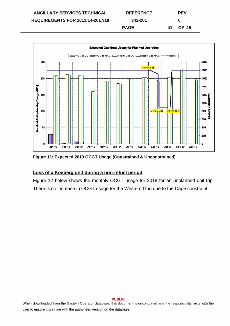
The expected monthly OCGTs usage for the Western Grid for 2019 during system
healthy conditions was determined for the load forecast given in Table 7. Figure 11
shows a monthly difference of 0 GWh.
ANCILLARY SERVICES TECHNICAL
REQUIREMENTS FOR 2013/14-2017/18
REFERENCE REV
342-201 0
PAGE 41 OF 45
PUBLIC When downloaded from the System Operator database, this document is uncontrolled and the responsibility rests with the
user to ensure it is in line with the authorised version on the database.
Figure 11: Expected 2019 OCGT Usage (Constrained & Unconstrained)
Loss of a Koeberg unit during a non-refuel period
Figure 12 below shows the monthly OCGT usage for 2018 for an unplanned unit trip.
There is no increase in OCGT usage for the Western Grid due to the Cape constraint.

ANCILLARY SERVICES TECHNICAL
REQUIREMENTS FOR 2013/14-2017/18
REFERENCE REV
342-201 0
PAGE 42 OF 45
PUBLIC When downloaded from the System Operator database, this document is uncontrolled and the responsibility rests with the
user to ensure it is in line with the authorised version on the database.
Figure 12: Expected 2018 OCGT Usage for Unplanned Reactor Trip
Loss of a Koeberg unit during a refuel period
Two refuel outages during which the in-service unit was tripped were considered. The
worst Western Gid energy period was again identified to establish the need for
constrained generation.
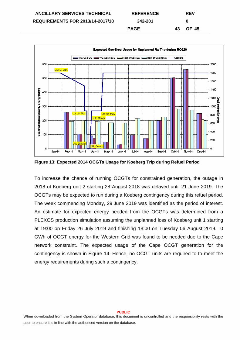
During outage RO220, Koeberg unit 1 was tripped on the Friday before the worst
energy week. 14.2 GWh of OCGT energy for the Western Grid was found to be needed
due to the Cape network constraint. The expected usage of the Cape OCGT generation
for the contingency is shown in Figure 13.
ANCILLARY SERVICES TECHNICAL
REQUIREMENTS FOR 2013/14-2017/18
REFERENCE REV
342-201 0
PAGE 43 OF 45
PUBLIC When downloaded from the System Operator database, this document is uncontrolled and the responsibility rests with the
user to ensure it is in line with the authorised version on the database.
Figure 13: Expected 2014 OCGTs Usage for Koeberg Trip during Refuel Period
To increase the chance of running OCGTs for constrained generation, the outage in
2018 of Koeberg unit 2 starting 28 August 2018 was delayed until 21 June 2019. The
OCGTs may be expected to run during a Koeberg contingency during this refuel period.
The week commencing Monday, 29 June 2019 was identified as the period of interest.
An estimate for expected energy needed from the OCGTs was determined from a
PLEXOS production simulation assuming the unplanned loss of Koeberg unit 1 starting
at 19:00 on Friday 26 July 2019 and finishing 18:00 on Tuesday 06 August 2019. 0
GWh of OCGT energy for the Western Grid was found to be needed due to the Cape
network constraint. The expected usage of the Cape OCGT generation for the
contingency is shown in Figure 14. Hence, no OCGT units are required to to meet the
energy requirements during such a contingency.

ANCILLARY SERVICES TECHNICAL
REQUIREMENTS FOR 2013/14-2017/18
REFERENCE REV
342-201 0
PAGE 44 OF 45
PUBLIC When downloaded from the System Operator database, this document is uncontrolled and the responsibility rests with the
user to ensure it is in line with the authorised version on the database.
Figure 14: Expected 2019 OCGTs Usage for Koeberg Trip during Refuel Period

ANCILLARY SERVICES TECHNICAL
REQUIREMENTS FOR 2013/14-2017/18
REFERENCE REV
342-201 0
PAGE 45 OF 45
PUBLIC When downloaded from the System Operator database, this document is uncontrolled and the responsibility rests with the
user to ensure it is in line with the authorised version on the database.
7.2. REFERENCES
1. Integrated Resource Plan for Electricity 2010 – 2030, Government Gazette, no.
34263, 06 May 2011
2. LE Jones, “Strategies and Decision Support Systems for Integrating Variable Energy
Resources in control Centres for Reliable Grid Operations”, post April 2011
3. “The South African Grid Code: The System Operator Code”, Rev 8.0 July 2010.
4. LNF de Villiers, Email of Medupi Spinning Specification with Commissioning of 2nd
Unit, 27 June 2013
5. “Transmission Development Plan 2012 – 2021”, GP Report 11/139
6. B Herbst, Email of Cape Strengthening Progress Outlook, 22 April 2013.
7. M Rampokanyo, Email of Cape Transfer Limits for 765 kV Strengthening, 30 April
2013.
8. JB van Wyk, “Koeberg 10 Year Production Plan – Rev 63”, 01 December 2012.
9. L. Nieuwoudt, “Provision of Requirements for Secure Off-site Power Supplies as
Required by the South African Grid Code: Koeberg Agreement with the System
Operator”, Document Number 922490R, January 2005.
10. J Janse Van Rensburg, Email of Load Forecast for Cape covering 2014/15 to
2019/20, 30 April 2013. Michael Barry, Email of National Forecasts “Forecasts”, 27
March 203, 11 April 2013.
11. D Matshidza, Eskom Grid Planning, Zeus-Omega 765 kV Integration, May 2011
12. Nomakhosi Sekane, Email of 2014_REPORT_F2014 Unipede F2014 Apr13_1.1.xlsx,
08 May 2013.
13. TA Carolin, “Managing a network for optimisation and safety”, Energize, March 2006.
14. Ancillary Services Technical Requirements for 2013/14-17/18, Document Number
342-89
15. Dumi Mtolo, “Instantaneous reserves studies for 2012”, Document Number 342-74