System Objects B - Schneider Electric · Unity Pro XLS Software System Objects ... the application...
25
33003885 07/2012 99 B Unity Pro XLS Software System Objects 33003885 07/2012 System Objects Introduction This chapter describes the system bits and words of the Quantum Safety PLC. Note: The symbols associated with each bit object or system word mentioned in the descriptive tables of these objects are not implemented as standard in the software, but can be entered using the data editor. It is suggested that the symbol names associated with the system bits and system words that appear on the following pages be implemented to provide continuity and ease of understanding. Example: %S0 COLDSTART (the user can select another word to replace COLDSTART). What Is in This Chapter? This chapter contains the following sections: Section Topic Page B.1 System Bits 100 B.2 System Words 109
Transcript of System Objects B - Schneider Electric · Unity Pro XLS Software System Objects ... the application...

33003885 07/2012 99
B
Unity Pro XLS Software
System Objects
33003885 07/2012
System Objects
Introduction
This chapter describes the system bits and words of the Quantum Safety PLC.
Note: The symbols associated with each bit object or system word mentioned in the
descriptive tables of these objects are not implemented as standard in the software,
but can be entered using the data editor.
It is suggested that the symbol names associated with the system bits and system
words that appear on the following pages be implemented to provide continuity and
ease of understanding. Example: %S0 COLDSTART (the user can select another
word to replace COLDSTART).
What Is in This Chapter?
This chapter contains the following sections:
Section Topic Page
B.1 System Bits 100
B.2 System Words 109

System Objects
100 33003885 07/2012
B.1 System Bits
Introduction
This section describes the system bits of the Quantum Safety PLC.
For your convenience, all system bits of standard Quantum PLCs are listed but only
explained further if used in the Quantum Safety PLC.
What Is in This Section?
This section contains the following topics:
Topic Page
System Bit Introduction 101
Description of the System Bits %S0 to %S13 102
Description of the System Bits %S15 to %S21 104
Description of the System Bits %S30 to %S51 106
Description of the System Bits %S59 to %S122 107

System Objects
33003885 07/2012 101
System Bit Introduction
General
The Quantum PLCs use %Si system bits which indicate the state of the PLC, or they
can be used to control how it operates.
These bits can be tested in the user program to detect any functional development.
Some of these bits must be reset to their initial or normal state by either the program
or the user. Other bits are automatically reset by the system. Finally, there are bits
which only display the status of the PLC.
System Objects
102 33003885 07/2012
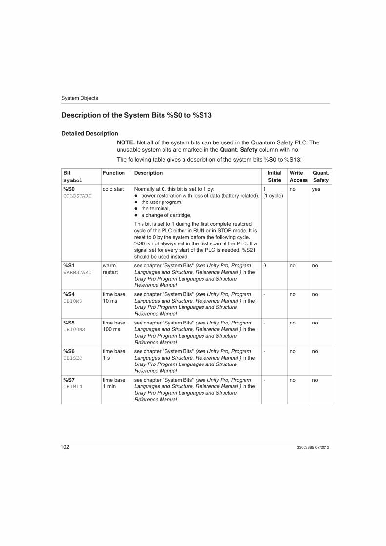
Description of the System Bits %S0 to %S13
Detailed Description
NOTE: Not all of the system bits can be used in the Quantum Safety PLC. The
unusable system bits are marked in the Quant. Safety column with no.
The following table gives a description of the system bits %S0 to %S13:
Bit
Symbol
Function Description Initial
State
Write
Access
Quant.
Safety
%S0
COLDSTART
cold start Normally at 0, this bit is set to 1 by:
power restoration with loss of data (battery related),
the user program,
the terminal,
a change of cartridge,
This bit is set to 1 during the first complete restored
cycle of the PLC either in RUN or in STOP mode. It is
reset to 0 by the system before the following cycle.
%S0 is not always set in the first scan of the PLC. If a
signal set for every start of the PLC is needed, %S21
should be used instead.
1
(1 cycle)
no yes
%S1
WARMSTART
warm
restart
see chapter "System Bits" (see Unity Pro, Program
Languages and Structure, Reference Manual ) in the
Unity Pro Program Languages and Structure
Reference Manual
0 no no
%S4
TB10MS
time base
10 ms
see chapter "System Bits" (see Unity Pro, Program
Languages and Structure, Reference Manual ) in the
Unity Pro Program Languages and Structure
Reference Manual
- no no
%S5
TB100MS
time base
100 ms
see chapter "System Bits" (see Unity Pro, Program
Languages and Structure, Reference Manual ) in the
Unity Pro Program Languages and Structure
Reference Manual
- no no
%S6
TB1SEC
time base
1 s
see chapter "System Bits" (see Unity Pro, Program
Languages and Structure, Reference Manual ) in the
Unity Pro Program Languages and Structure
Reference Manual
- no no
%S7
TB1MIN
time base
1 min
see chapter "System Bits" (see Unity Pro, Program
Languages and Structure, Reference Manual ) in the
Unity Pro Program Languages and Structure
Reference Manual
- no no
System Objects
33003885 07/2012 103
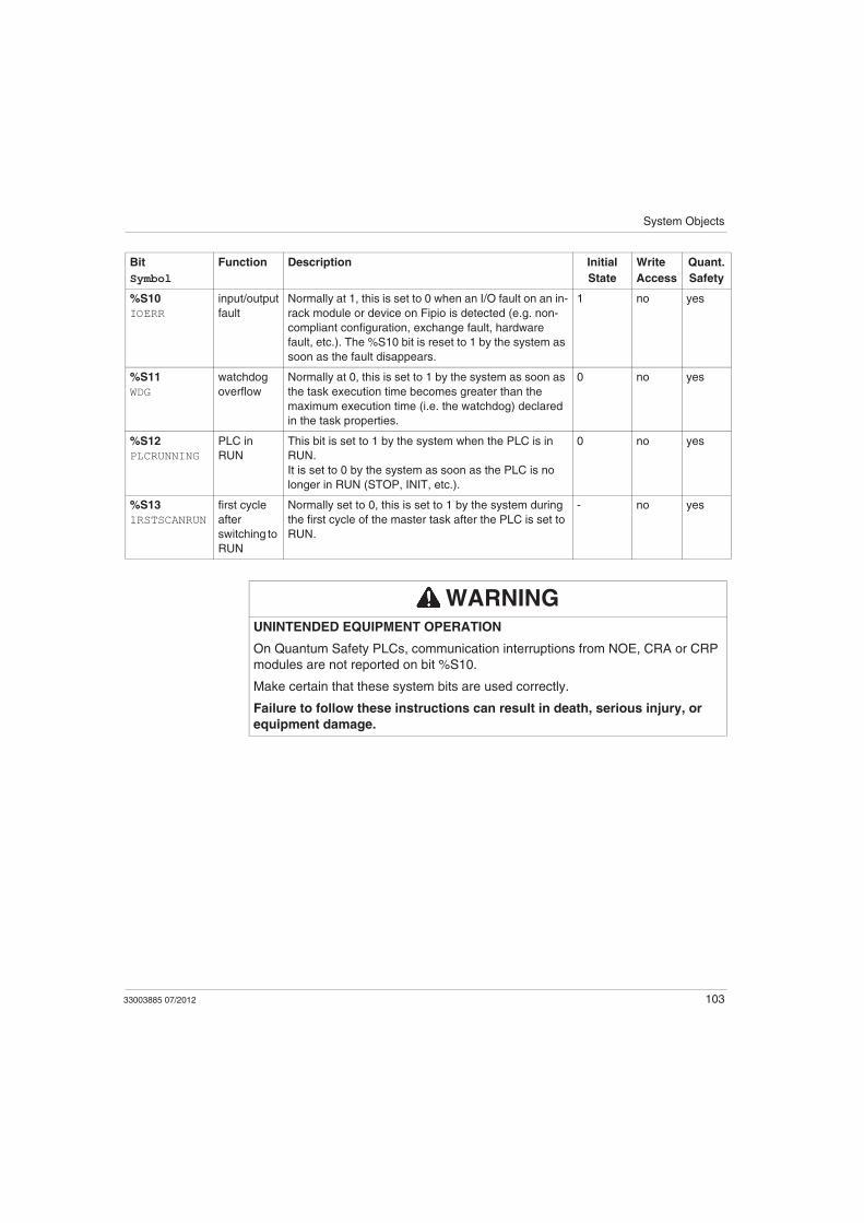
%S10
IOERR
input/output
fault
Normally at 1, this is set to 0 when an I/O fault on an in-
rack module or device on Fipio is detected (e.g. non-
compliant configuration, exchange fault, hardware
fault, etc.). The %S10 bit is reset to 1 by the system as
soon as the fault disappears.
1 no yes
%S11
WDG
watchdog
overflow
Normally at 0, this is set to 1 by the system as soon as
the task execution time becomes greater than the
maximum execution time (i.e. the watchdog) declared
in the task properties.
0 no yes
%S12
PLCRUNNING
PLC in
RUN
This bit is set to 1 by the system when the PLC is in
RUN.
It is set to 0 by the system as soon as the PLC is no
longer in RUN (STOP, INIT, etc.).
0 no yes
%S13
1RSTSCANRUN
first cycle
after
switching to
RUN
Normally set to 0, this is set to 1 by the system during
the first cycle of the master task after the PLC is set to
RUN.
- no yes
Bit
Symbol
Function Description Initial
State
Write
Access
Quant.
Safety
WARNINGUNINTENDED EQUIPMENT OPERATION
On Quantum Safety PLCs, communication interruptions from NOE, CRA or CRP
modules are not reported on bit %S10.
Make certain that these system bits are used correctly.
Failure to follow these instructions can result in death, serious injury, or
equipment damage.

System Objects
104 33003885 07/2012
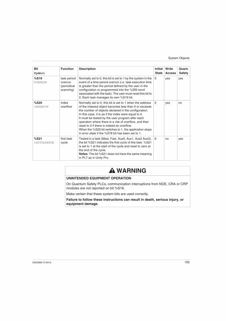
Description of the System Bits %S15 to %S21
Detailed Description
NOTE: Not all of the system bits can be used in the Quantum Safety PLC. The
unusable system bits are marked in the Quant. Safety column with no.
The following table gives a description of the system bits %S15 to %S21:
Bit
Symbol
Function Description Initial
State
Write
Access
Quant.
Safety
%S15
STRINGERROR
character
string fault
see chapter "System Bits" (see Unity Pro, Program
Languages and Structure, Reference Manual ) in the
Unity Pro Program Languages and Structure
Reference Manual
0 yes no
%S16
IOERRTSK
task
input/output
fault
Normally set to 1, this bit is set to 0 by the system when
a fault occurs on an in-rack I/O module or a Fipio device
configured in the task.
This bit must be reset to 1 by the user.
1 yes yes
%S17
CARRY
rotate or
shift output
normally at 0
During a rotate or shift operation, this bit takes the state
of the outgoing bit.
0 no yes
%S18
OVERFLOW
overflow or
arithmetic
error
Normally set to 0, this bit is set to 1 in the event of a
capacity overflow if there is
a result greater than + 32 767 or less than - 32 768,
in single length,
result greater than + 65 535, in unsigned integer,
a result greater than + 2 147 483 647 or less than -
2 147 483 648, in double length,
result greater than +4 294 967 296, in double length
or unsigned integer,
real values outside limits,
division by 0,
the root of a negative number,
forcing to a non-existent step on a drum,
stacking up of an already full register, emptying of
an already empty register.
It must be tested by the user program after each
operation where there is a risk of overflow, and then
reset to 0 by the user if there is indeed an overflow.
When the %S18 bit switches to 1, the application stops
in error state if the %S78 bit has been set to 1.
0 yes yes
System Objects
33003885 07/2012 105
%S19
OVERRUN
task period
overrun
(periodical
scanning)
Normally set to 0, this bit is set to 1 by the system in the
event of a time period overrun (i.e. task execution time
is greater than the period defined by the user in the
configuration or programmed into the %SW word
associated with the task). The user must reset this bit to
0. Each task manages its own %S19 bit.
0 yes yes
%S20
INDEXOVF
Index
overflow
Normally set to 0, this bit is set to 1 when the address
of the indexed object becomes less than 0 or exceeds
the number of objects declared in the configuration.
In this case, it is as if the index were equal to 0.
It must be tested by the user program after each
operation where there is a risk of overflow, and then
reset to 0 if there is indeed an overflow.
When the %S20 bit switches to 1, the application stops
in error state if the %S78 bit has been set to 1.
0 yes no
%S21
1RSTTASKRUN
first task
cycle
Tested in a task (Mast, Fast, Aux0, Aux1, Aux2 Aux3),
the bit %S21 indicates the first cycle of this task. %S21
is set to 1 at the start of the cycle and reset to zero at
the end of the cycle.
Notes: The bit %S21 does not have the same meaning
in PL7 as in Unity Pro.
0 no yes
Bit
Symbol
Function Description Initial
State
Write
Access
Quant.
Safety
WARNINGUNINTENDED EQUIPMENT OPERATION
On Quantum Safety PLCs, communication interruptions from NOE, CRA or CRP
modules are not reported on bit %S16.
Make certain that these system bits are used correctly.
Failure to follow these instructions can result in death, serious injury, or
equipment damage.
System Objects
106 33003885 07/2012
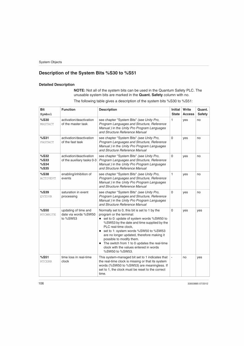
Description of the System Bits %S30 to %S51
Detailed Description
NOTE: Not all of the system bits can be used in the Quantum Safety PLC. The
unusable system bits are marked in the Quant. Safety column with no.
The following table gives a description of the system bits %S30 to %S51:
Bit
Symbol
Function Description Initial
State
Write
Access
Quant.
Safety
%S30
MASTACT
activation/deactivation
of the master task
see chapter "System Bits" (see Unity Pro,
Program Languages and Structure, Reference
Manual ) in the Unity Pro Program Languages
and Structure Reference Manual
1 yes no
%S31
FASTACT
activation/deactivation
of the fast task
see chapter "System Bits" (see Unity Pro,
Program Languages and Structure, Reference
Manual ) in the Unity Pro Program Languages
and Structure Reference Manual
0 yes no
%S32
%S33
%S34
%S35
activation/deactivation
of the auxiliary tasks 0-3
see chapter "System Bits" (see Unity Pro,
Program Languages and Structure, Reference
Manual ) in the Unity Pro Program Languages
and Structure Reference Manual
0 yes no
%S38
ACTIVEVT
enabling/inhibition of
events
see chapter "System Bits" (see Unity Pro,
Program Languages and Structure, Reference
Manual ) in the Unity Pro Program Languages
and Structure Reference Manual
1 yes no
%S39
EVTOVR
saturation in event
processing
see chapter "System Bits" (see Unity Pro,
Program Languages and Structure, Reference
Manual ) in the Unity Pro Program Languages
and Structure Reference Manual
0 yes no
%S50
RTCWRITE
updating of time and
date via words %SW50
to %SW53
Normally set to 0, this bit is set to 1 by the
program or the terminal:
set to 0: update of system words %SW50 to
%SW53 by the date and time supplied by the
PLC real-time clock,
set to 1: system words %SW50 to %SW53
are no longer updated, therefore making it
possible to modify them.
The switch from 1 to 0 updates the real-time
clock with the values entered in words
%SW50 to %SW53.
0 yes yes
%S51
RTCERR
time loss in real-time
clock
This system-managed bit set to 1 indicates that
the real-time clock is missing or that its system
words (%SW50 to %SW53) are meaningless. If
set to 1, the clock must be reset to the correct
time.
- no yes
System Objects
33003885 07/2012 107
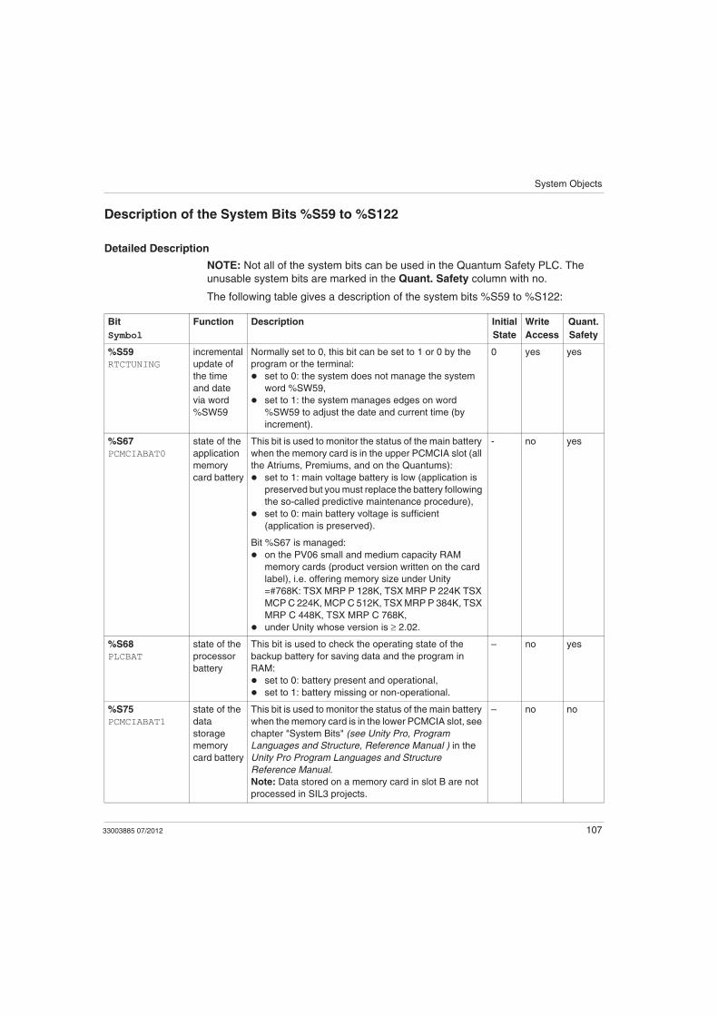
Description of the System Bits %S59 to %S122
Detailed Description
NOTE: Not all of the system bits can be used in the Quantum Safety PLC. The
unusable system bits are marked in the Quant. Safety column with no.
The following table gives a description of the system bits %S59 to %S122:
Bit
Symbol
Function Description Initial
State
Write
Access
Quant.
Safety
%S59
RTCTUNING
incremental
update of
the time
and date
via word
%SW59
Normally set to 0, this bit can be set to 1 or 0 by the
program or the terminal:
set to 0: the system does not manage the system
word %SW59,
set to 1: the system manages edges on word
%SW59 to adjust the date and current time (by
increment).
0 yes yes
%S67
PCMCIABAT0
state of the
application
memory
card battery
This bit is used to monitor the status of the main battery
when the memory card is in the upper PCMCIA slot (all
the Atriums, Premiums, and on the Quantums):
set to 1: main voltage battery is low (application is
preserved but you must replace the battery following
the so-called predictive maintenance procedure),
set to 0: main battery voltage is sufficient
(application is preserved).
Bit %S67 is managed:
on the PV06 small and medium capacity RAM
memory cards (product version written on the card
label), i.e. offering memory size under Unity
=#768K: TSX MRP P 128K, TSX MRP P 224K TSX
MCP C 224K, MCP C 512K, TSX MRP P 384K, TSX
MRP C 448K, TSX MRP C 768K,
under Unity whose version is ≥ 2.02.
- no yes
%S68
PLCBAT
state of the
processor
battery
This bit is used to check the operating state of the
backup battery for saving data and the program in
RAM:
set to 0: battery present and operational,
set to 1: battery missing or non-operational.
– no yes
%S75
PCMCIABAT1
state of the
data
storage
memory
card battery
This bit is used to monitor the status of the main battery
when the memory card is in the lower PCMCIA slot, see
chapter "System Bits" (see Unity Pro, Program
Languages and Structure, Reference Manual ) in the
Unity Pro Program Languages and Structure
Reference Manual.
Note: Data stored on a memory card in slot B are not
processed in SIL3 projects.
– no no
System Objects
108 33003885 07/2012
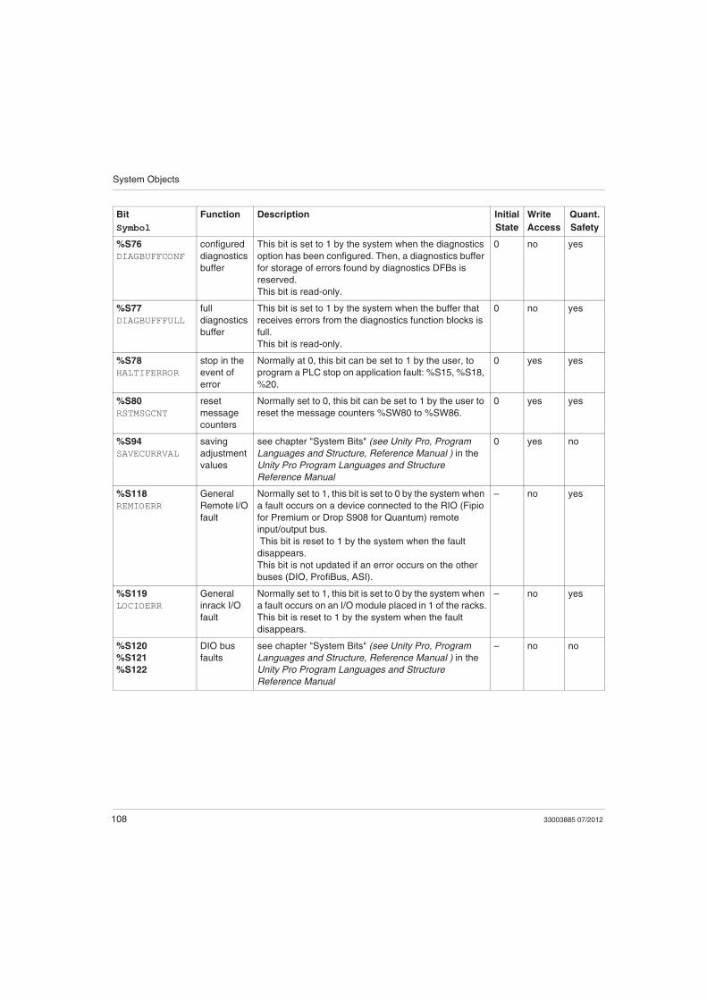
%S76
DIAGBUFFCONF
configured
diagnostics
buffer
This bit is set to 1 by the system when the diagnostics
option has been configured. Then, a diagnostics buffer
for storage of errors found by diagnostics DFBs is
reserved.
This bit is read-only.
0 no yes
%S77
DIAGBUFFFULL
full
diagnostics
buffer
This bit is set to 1 by the system when the buffer that
receives errors from the diagnostics function blocks is
full.
This bit is read-only.
0 no yes
%S78
HALTIFERROR
stop in the
event of
error
Normally at 0, this bit can be set to 1 by the user, to
program a PLC stop on application fault: %S15, %S18,
%20.
0 yes yes
%S80
RSTMSGCNT
reset
message
counters
Normally set to 0, this bit can be set to 1 by the user to
reset the message counters %SW80 to %SW86.
0 yes yes
%S94
SAVECURRVAL
saving
adjustment
values
see chapter "System Bits" (see Unity Pro, Program
Languages and Structure, Reference Manual ) in the
Unity Pro Program Languages and Structure
Reference Manual
0 yes no
%S118
REMIOERR
General
Remote I/O
fault
Normally set to 1, this bit is set to 0 by the system when
a fault occurs on a device connected to the RIO (Fipio
for Premium or Drop S908 for Quantum) remote
input/output bus.
This bit is reset to 1 by the system when the fault
disappears.
This bit is not updated if an error occurs on the other
buses (DIO, ProfiBus, ASI).
– no yes
%S119
LOCIOERR
General
inrack I/O
fault
Normally set to 1, this bit is set to 0 by the system when
a fault occurs on an I/O module placed in 1 of the racks.
This bit is reset to 1 by the system when the fault
disappears.
– no yes
%S120
%S121
%S122
DIO bus
faults
see chapter "System Bits" (see Unity Pro, Program
Languages and Structure, Reference Manual ) in the
Unity Pro Program Languages and Structure
Reference Manual
– no no
Bit
Symbol
Function Description Initial
State
Write
Access
Quant.
Safety
System Objects
33003885 07/2012 109
B.2 System Words
Introduction
This section describes the system words of the Quantum Safety PLC.
For your convenience, all system words of standard Quantum PLCs are listed but
only explained further if used in the Quantum Safety PLC.
What Is in This Section?
This section contains the following topics:
Topic Page
Description of the System Words %SW0 to %SW21 110
Description of the System Words %SW30 to %SW59 113
Description of the System Words %SW60 to %SW127 117
System Objects
110 33003885 07/2012
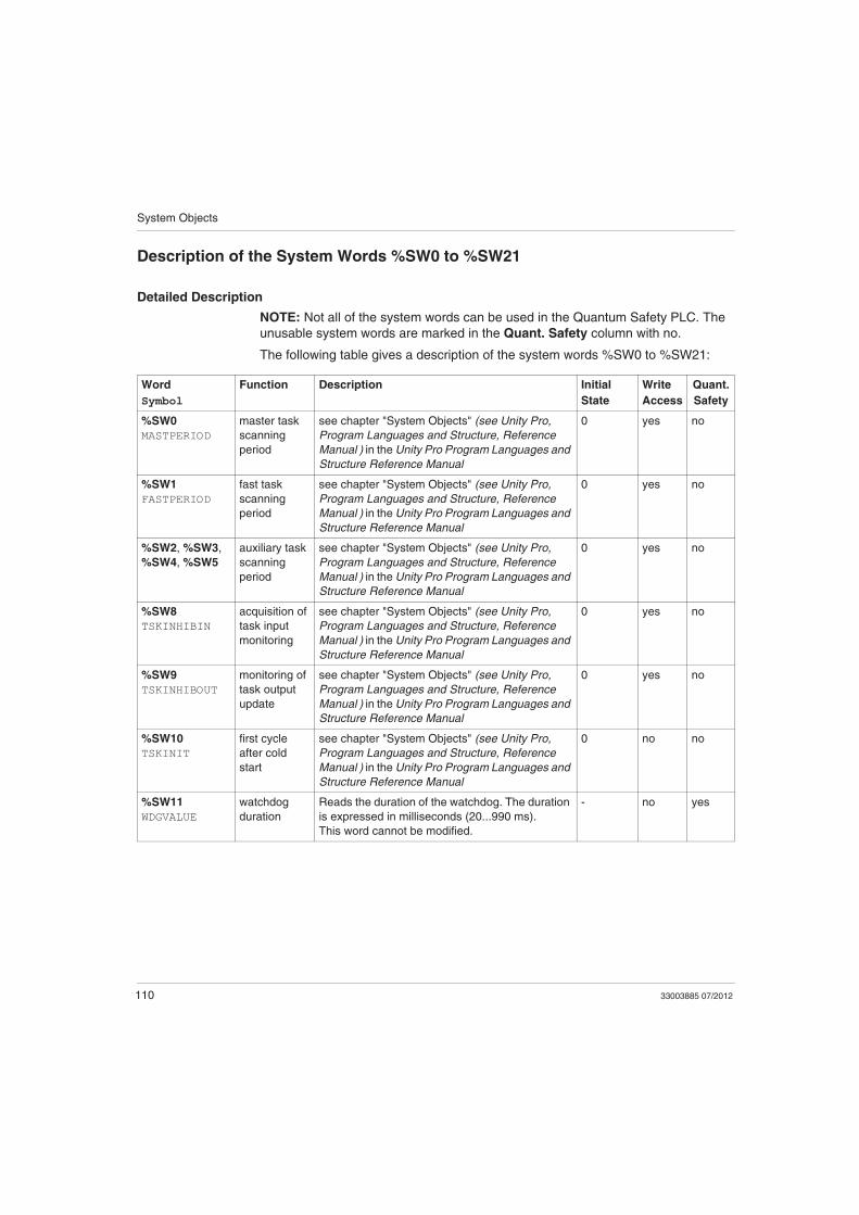
Description of the System Words %SW0 to %SW21
Detailed Description
NOTE: Not all of the system words can be used in the Quantum Safety PLC. The
unusable system words are marked in the Quant. Safety column with no.
The following table gives a description of the system words %SW0 to %SW21:
Word
Symbol
Function Description Initial
State
Write
Access
Quant.
Safety
%SW0
MASTPERIOD
master task
scanning
period
see chapter "System Objects" (see Unity Pro,
Program Languages and Structure, Reference
Manual ) in the Unity Pro Program Languages and
Structure Reference Manual
0 yes no
%SW1
FASTPERIOD
fast task
scanning
period
see chapter "System Objects" (see Unity Pro,
Program Languages and Structure, Reference
Manual ) in the Unity Pro Program Languages and
Structure Reference Manual
0 yes no
%SW2, %SW3,
%SW4, %SW5
auxiliary task
scanning
period
see chapter "System Objects" (see Unity Pro,
Program Languages and Structure, Reference
Manual ) in the Unity Pro Program Languages and
Structure Reference Manual
0 yes no
%SW8
TSKINHIBIN
acquisition of
task input
monitoring
see chapter "System Objects" (see Unity Pro,
Program Languages and Structure, Reference
Manual ) in the Unity Pro Program Languages and
Structure Reference Manual
0 yes no
%SW9
TSKINHIBOUT
monitoring of
task output
update
see chapter "System Objects" (see Unity Pro,
Program Languages and Structure, Reference
Manual ) in the Unity Pro Program Languages and
Structure Reference Manual
0 yes no
%SW10
TSKINIT
first cycle
after cold
start
see chapter "System Objects" (see Unity Pro,
Program Languages and Structure, Reference
Manual ) in the Unity Pro Program Languages and
Structure Reference Manual
0 no no
%SW11
WDGVALUE
watchdog
duration
Reads the duration of the watchdog. The duration
is expressed in milliseconds (20...990 ms).
This word cannot be modified.
- no yes
System Objects
33003885 07/2012 111
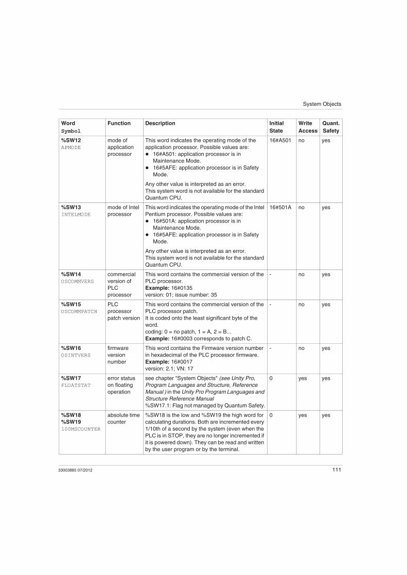
%SW12
APMODE
mode of
application
processor
This word indicates the operating mode of the
application processor. Possible values are:
16#A501: application processor is in
Maintenance Mode.
16#5AFE: application processor is in Safety
Mode.
Any other value is interpreted as an error.
This system word is not available for the standard
Quantum CPU.
16#A501 no yes
%SW13
INTELMODE
mode of Intel
processor
This word indicates the operating mode of the Intel
Pentium processor. Possible values are:
16#501A: application processor is in
Maintenance Mode.
16#5AFE: application processor is in Safety
Mode.
Any other value is interpreted as an error.
This system word is not available for the standard
Quantum CPU.
16#501A no yes
%SW14
OSCOMMVERS
commercial
version of
PLC
processor
This word contains the commercial version of the
PLC processor.
Example: 16#0135
version: 01; issue number: 35
- no yes
%SW15
OSCOMMPATCH
PLC
processor
patch version
This word contains the commercial version of the
PLC processor patch.
It is coded onto the least significant byte of the
word.
coding: 0 = no patch, 1 = A, 2 = B...
Example: 16#0003 corresponds to patch C.
- no yes
%SW16
OSINTVERS
firmware
version
number
This word contains the Firmware version number
in hexadecimal of the PLC processor firmware.
Example: 16#0017
version: 2.1; VN: 17
- no yes
%SW17
FLOATSTAT
error status
on floating
operation
see chapter "System Objects" (see Unity Pro,
Program Languages and Structure, Reference
Manual ) in the Unity Pro Program Languages and
Structure Reference Manual
%SW17.1: Flag not managed by Quantum Safety.
0 yes yes
%SW18
%SW19
100MSCOUNTER
absolute time
counter
%SW18 is the low and %SW19 the high word for
calculating durations. Both are incremented every
1/10th of a second by the system (even when the
PLC is in STOP, they are no longer incremented if
it is powered down). They can be read and written
by the user program or by the terminal.
0 yes yes
Word
Symbol
Function Description Initial
State
Write
Access
Quant.
Safety
System Objects
112 33003885 07/2012
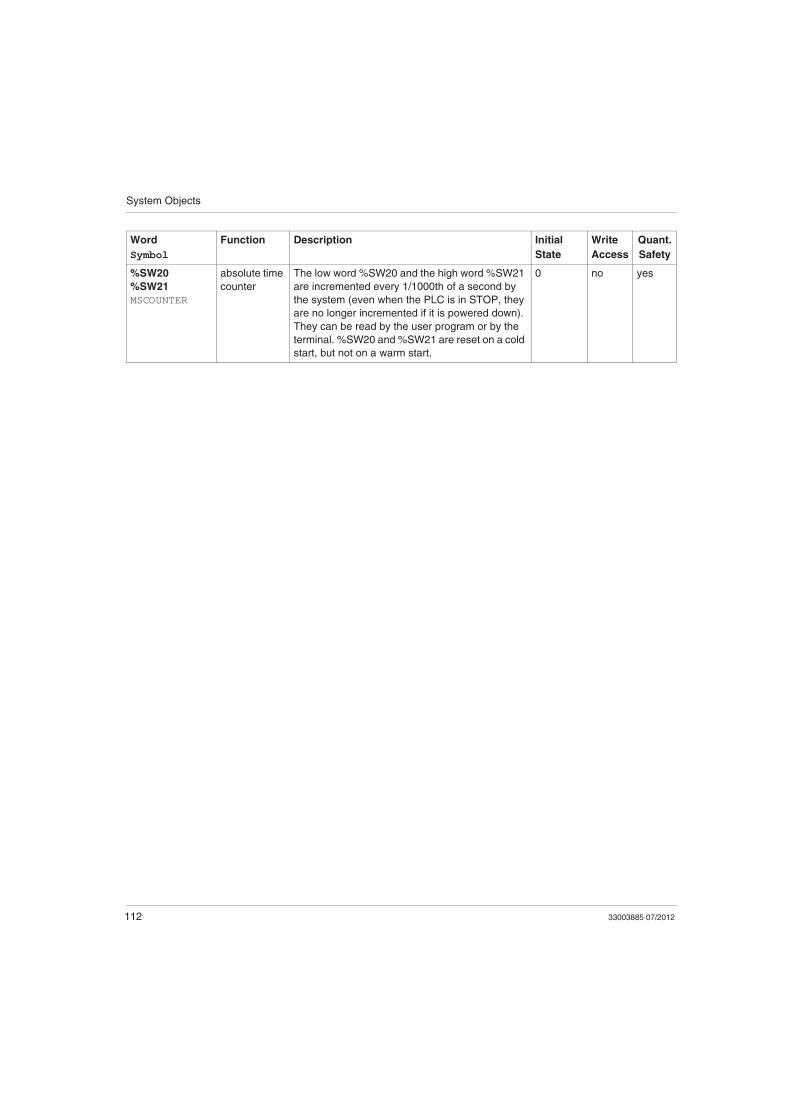
%SW20
%SW21
MSCOUNTER
absolute time
counter
The low word %SW20 and the high word %SW21
are incremented every 1/1000th of a second by
the system (even when the PLC is in STOP, they
are no longer incremented if it is powered down).
They can be read by the user program or by the
terminal. %SW20 and %SW21 are reset on a cold
start, but not on a warm start.
0 no yes
Word
Symbol
Function Description Initial
State
Write
Access
Quant.
Safety

System Objects
33003885 07/2012 113
Description of the System Words %SW30 to %SW59
Detailed Description
NOTE: Not all of the system words can be used in the Quantum Safety PLC. The
unusable system words are marked in the Quant. Safety column with no.
The following table gives a description of the system words %SW30 to %SW59:
Word
Symbol
Function Description Initial
State
Write
Access
Quant.
Safety
%SW30
MASTCURRTIME
master task
execution time
This word indicates the execution time of the last
master task cycle (in ms).
- no no
%SW31
MASTMAXTIME
maximum
master task
execution time
This word indicates the longest master task
execution time since the last cold start (in ms).
- no yes
%SW32
MASTMINTIME
minimum
master task
execution time
This word indicates the shortest master task
execution time since the last cold start (in ms).
- no yes
%SW33 to
%SW35
fast task
execution
times
see chapter "System Objects" (see Unity Pro,
Program Languages and Structure, Reference
Manual ) in the Unity Pro Program Languages and
Structure Reference Manual
- no no
%SW36 NTP number of
seconds (LSB)
This word indicates the number of seconds
passed since January 1st, 1980 at 00:00 (LSB
part). It reflects the NTP time coming from the
140 NOE 771 11 module. This word is refreshed
internally between two NTP synchronizations.
0 no yes
%SW37 NTP number of
seconds
(MSB)
This word indicates the number of seconds
passed since January 1st, 1980 at 00:00 (MSB
part). It reflects the NTP time coming from the
140 NOE 771 11 module. This word is refreshed
internally between two NTP synchronizations.
0 no yes
%SW38 NTP number of
milliseconds
This word indicates the number of milliseconds
added to the NTP number of seconds (%SW36
and %SW37). It reflects the NTP time coming
from the 140 NOE 771 11 module. This word is
refreshed internally between two NTP
synchronizations.
0 no yes
System Objects
114 33003885 07/2012
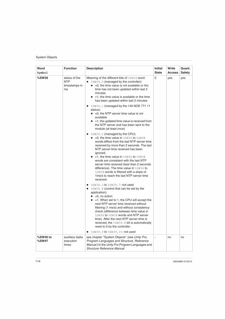
%SW39 status of the
NTP
timestamps in
ms
Meaning of the different bits of %SW39 word:
%SW39.0 (managed by the controller):
=0, the time value is not available or the
time has not been updated within last 2
minutes
=1, the time value is available or the time
has been updated within last 2 minutes
%SW39.1 (managed by the 140 NOE 771 11
status):
=0, the NTP server time value is not
available
=1, the updated time value is received from
the NTP server and has been sent to the
module (at least once)
%SW39.2 (managed by the CPU):
=0, the time value in %SW36 to %SW38
words differs from the last NTP server time
received by more than 2 seconds. The last
NTP server time received has been
ignored.
=1, the time value in %SW36 to %SW38
words are consistent with the last NTP
server time received (less than 2 seconds
difference). The time value in %SW36 to
%SW38 words is filtered with a slope of
1ms/s to reach the last NTP server time
received.
%SW39.3 to %SW39.7: not used
%SW39.8 (control that can be set by the
application):
=0, no action
=1. When set to 1, the CPU will accept the
next NTP server time received without
filtering (1 ms/s) and without consistency
check (difference between time value in
%SW36 to %SW38 words and NTP server
time). After the next NTP server time is
received, the %SW39.8 bit is automatically
reset to 0 by the controller.
%SW39.9 to %SW39.15: not used
0 yes yes
%SW40 to
%SW47
auxiliary tasks
execution
times
see chapter "System Objects" (see Unity Pro,
Program Languages and Structure, Reference
Manual ) in the Unity Pro Program Languages and
Structure Reference Manual
- no no
Word
Symbol
Function Description Initial
State
Write
Access
Quant.
Safety

System Objects
33003885 07/2012 115
%SW48
IOEVTNB
number of
events
see chapter "System Objects" (see Unity Pro,
Program Languages and Structure, Reference
Manual ) in the Unity Pro Program Languages and
Structure Reference Manual
0 yes no
%SW49
DAYOFWEEK
%SW50
SEC
%SW51
HOURMIN
%SW52
MONTHDAY
%SW53
YEAR
real-time clock
function
System words containing date and current time (in
BCD):
%SW49: day of the week:
1 = Monday,
2 = Tuesday,
3 = Wednesday,
4 = Thursday,
5 = Friday,
6 = Saturday,
7 = Sunday,
%SW50: Seconds (16#SS00),
%SW51: Hours and Minutes (16#HHMM),
%SW52: Month and Day (16#MMDD),
%SW53: Year (16#YYYY).
These words are managed by the system when
the bit %S50 is set to 0.
These words can be written by the user program
or by the terminal when the bit %S50 is set to 1.
- yes yes
%SW54
STOPSEC
%SW55
STOPHM
%SW56
STOPMD
%SW57
STOPYEAR
%SW58
STOPDAY
real-time clock
function on last
stop
System words containing date and time of the last
power outage or PLC stop (in Binary Coded
Decimal):
%SW54: Seconds (00SS),
%SW55: Hours and Minutes (HHMM),
%SW56: Month and Day (MMDD),
%SW57: Year (YYYY),
%SW58: the most significant byte contains the
day of the week (1 for Monday through to 7 for
Sunday), and the least significant byte
contains the code for the last stop:
1 = change from RUN to STOP by the
terminal or the dedicated input,
2 = stop by watchdog (PLC task or SFC
overrun),
4 = power outage or memory card lock
operation,
5 = stop on hardware fault,
6 = stop on software fault. Details on the
type of software fault are stored in
%SW125.
- no yes
Word
Symbol
Function Description Initial
State
Write
Access
Quant.
Safety
System Objects
116 33003885 07/2012
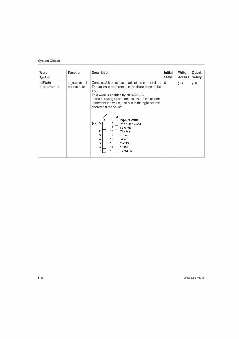
%SW59
ADJDATETIME
adjustment of
current date
Contains 2 8-bit series to adjust the current date.
The action is performed on the rising edge of the
bit.
This word is enabled by bit %S59=1.
In the following illustration, bits in the left column
increment the value, and bits in the right column
decrement the value:
0 yes yes
Word
Symbol
Function Description Initial
State
Write
Access
Quant.
Safety
System Objects
33003885 07/2012 117
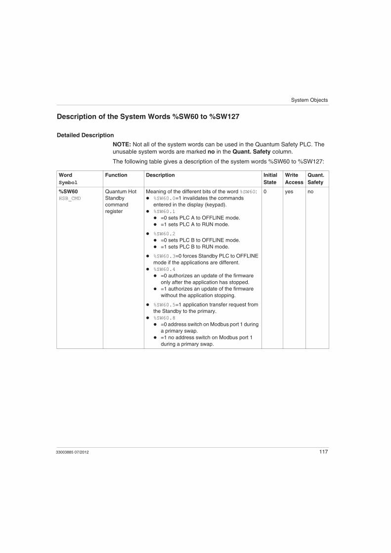
Description of the System Words %SW60 to %SW127
Detailed Description
NOTE: Not all of the system words can be used in the Quantum Safety PLC. The
unusable system words are marked no in the Quant. Safety column.
The following table gives a description of the system words %SW60 to %SW127:
Word
Symbol
Function Description Initial
State
Write
Access
Quant.
Safety
%SW60
HSB_CMD
Quantum Hot
Standby
command
register
Meaning of the different bits of the word %SW60:
%SW60.0=1 invalidates the commands
entered in the display (keypad).
%SW60.1
=0 sets PLC A to OFFLINE mode.
=1 sets PLC A to RUN mode.
%SW60.2
=0 sets PLC B to OFFLINE mode.
=1 sets PLC B to RUN mode.
%SW60.3=0 forces Standby PLC to OFFLINE
mode if the applications are different.
%SW60.4
=0 authorizes an update of the firmware
only after the application has stopped.
=1 authorizes an update of the firmware
without the application stopping.
%SW60.5=1 application transfer request from
the Standby to the primary.
%SW60.8
=0 address switch on Modbus port 1 during
a primary swap.
=1 no address switch on Modbus port 1
during a primary swap.
0 yes no
System Objects
118 33003885 07/2012
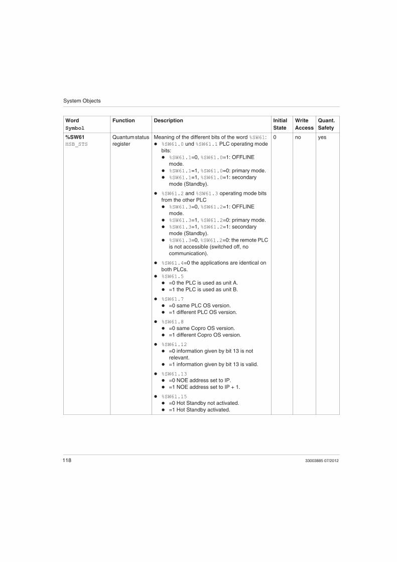
%SW61
HSB_STS
Quantum status
register
Meaning of the different bits of the word %SW61:
%SW61.0 und %SW61.1 PLC operating mode
bits:
%SW61.1=0, %SW61.0=1: OFFLINE
mode.
%SW61.1=1, %SW61.0=0: primary mode.
%SW61.1=1, %SW61.0=1: secondary
mode (Standby).
%SW61.2 and %SW61.3 operating mode bits
from the other PLC
%SW61.3=0, %SW61.2=1: OFFLINE
mode.
%SW61.3=1, %SW61.2=0: primary mode.
%SW61.3=1, %SW61.2=1: secondary
mode (Standby).
%SW61.3=0, %SW61.2=0: the remote PLC
is not accessible (switched off, no
communication).
%SW61.4=0 the applications are identical on
both PLCs.
%SW61.5
=0 the PLC is used as unit A.
=1 the PLC is used as unit B.
%SW61.7
=0 same PLC OS version.
=1 different PLC OS version.
%SW61.8
=0 same Copro OS version.
=1 different Copro OS version.
%SW61.12
=0 information given by bit 13 is not
relevant.
=1 information given by bit 13 is valid.
%SW61.13
=0 NOE address set to IP.
=1 NOE address set to IP + 1.
%SW61.15
=0 Hot Standby not activated.
=1 Hot Standby activated.
0 no yes
Word
Symbol
Function Description Initial
State
Write
Access
Quant.
Safety

System Objects
33003885 07/2012 119
%SW62
HSBY_REVERSE0
%SW63
HSBY_REVERSE1
transfer word These 2 words may be written by the user in the
first section of the master task. They are then
transferred automatically from the Standby
processor to update the primary PLC.
They may be read on the primary PLC and be
used as primary application parameters.
0 yes yes
%SW70
WEEKOFYEAR
real-time clock
function
System word containing the number of the week
in the year: 1 to 52.
– yes
%SW71
KEY_SWITCH
position of the
switches on the
Quantum front
panel
This word provides the image of the positions of
the switches on the front panel of the Quantum
processor. This word is updated automatically by
the system.
%SW71.0 = 1 switch in the "Memory
protected" position,
%SW71.1 = 1 switch in the "STOP" position,
%SW71.2 = 1 switch in the "START" position,
%SW71.8 = 1 switch in the "MEM" position,
%SW71.9 = 1 switch in the "ASCII" position,
%SW71.10 = 1 switch in the "RTU" position,
%SW71.3 to 7 and 11 to 15 are not used.
0 no yes
%SW75
TIMEREVTNB
timer-type
event counter
see chapter "System Objects" (see Unity Pro,
Program Languages and Structure, Reference
Manual ) in the Unity Pro Program Languages
and Structure Reference Manual
0 no
%SW76
DLASTREG
diagnostics
function:
recording
Result of the last registration:
= 0 if the recording was successful,
= 1 if the diagnostics buffer has not been
configured,
= 2 if the diagnostics buffer is full.
0 yes
%SW77
DLASTDEREG
diagnostics
function: non-
recording
Result of the last deregistration:
= 0 if the non-recording was successful,
= 1 if the diagnostics buffer has not been
configured,
= 21 if the error identifier is invalid,
= 22 if the error has not been recorded.
0 yes
%SW78
DNBERRBUF
diagnostics
function:
number of
errors
Number of errors currently in the diagnostics
buffer.
0 yes
Word
Symbol
Function Description Initial
State
Write
Access
Quant.
Safety
System Objects
120 33003885 07/2012
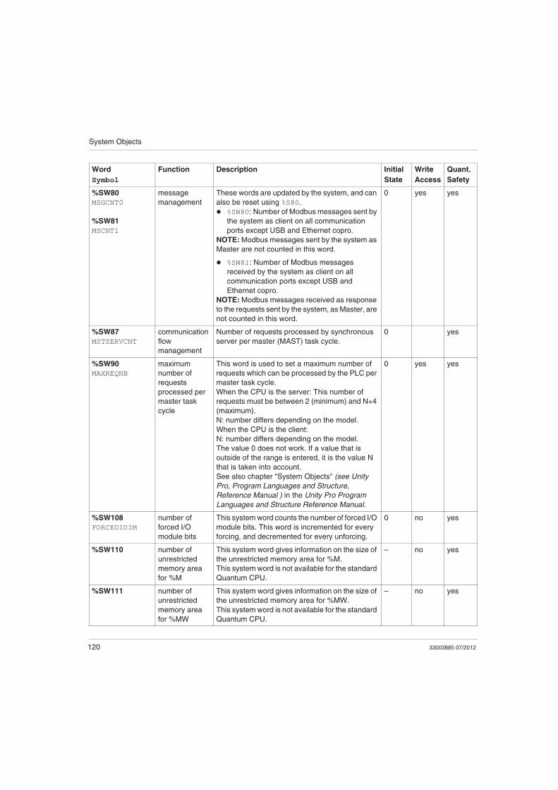
%SW80
MSGCNT0
%SW81
MSCNT1
message
management
These words are updated by the system, and can
also be reset using %S80.
%SW80: Number of Modbus messages sent by
the system as client on all communication
ports except USB and Ethernet copro.
NOTE: Modbus messages sent by the system as
Master are not counted in this word.
%SW81: Number of Modbus messages
received by the system as client on all
communication ports except USB and
Ethernet copro.
NOTE: Modbus messages received as response
to the requests sent by the system, as Master, are
not counted in this word.
0 yes yes
%SW87
MSTSERVCNT
communication
flow
management
Number of requests processed by synchronous
server per master (MAST) task cycle.
0 yes
%SW90
MAXREQNB
maximum
number of
requests
processed per
master task
cycle
This word is used to set a maximum number of
requests which can be processed by the PLC per
master task cycle.
When the CPU is the server: This number of
requests must be between 2 (minimum) and N+4
(maximum).
N: number differs depending on the model.
When the CPU is the client:
N: number differs depending on the model.
The value 0 does not work. If a value that is
outside of the range is entered, it is the value N
that is taken into account.
See also chapter "System Objects" (see Unity
Pro, Program Languages and Structure,
Reference Manual ) in the Unity Pro Program
Languages and Structure Reference Manual.
0 yes yes
%SW108
FORCEDIOIM
number of
forced I/O
module bits
This system word counts the number of forced I/O
module bits. This word is incremented for every
forcing, and decremented for every unforcing.
0 no yes
%SW110 number of
unrestricted
memory area
for %M
This system word gives information on the size of
the unrestricted memory area for %M.
This system word is not available for the standard
Quantum CPU.
– no yes
%SW111 number of
unrestricted
memory area
for %MW
This system word gives information on the size of
the unrestricted memory area for %MW.
This system word is not available for the standard
Quantum CPU.
– no yes
Word
Symbol
Function Description Initial
State
Write
Access
Quant.
Safety
System Objects
33003885 07/2012 121
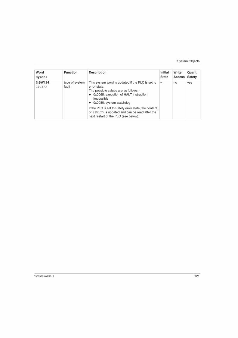
%SW124
CPUERR
type of system
fault
This system word is updated if the PLC is set to
error state.
The possible values are as follows:
0x0065: execution of HALT instruction
impossible
0x0080: system watchdog
If the PLC is set to Safety error state, the content
of %SW125 is updated and can be read after the
next restart of the PLC (see below).
– no yes
Word
Symbol
Function Description Initial
State
Write
Access
Quant.
Safety
System Objects
122 33003885 07/2012
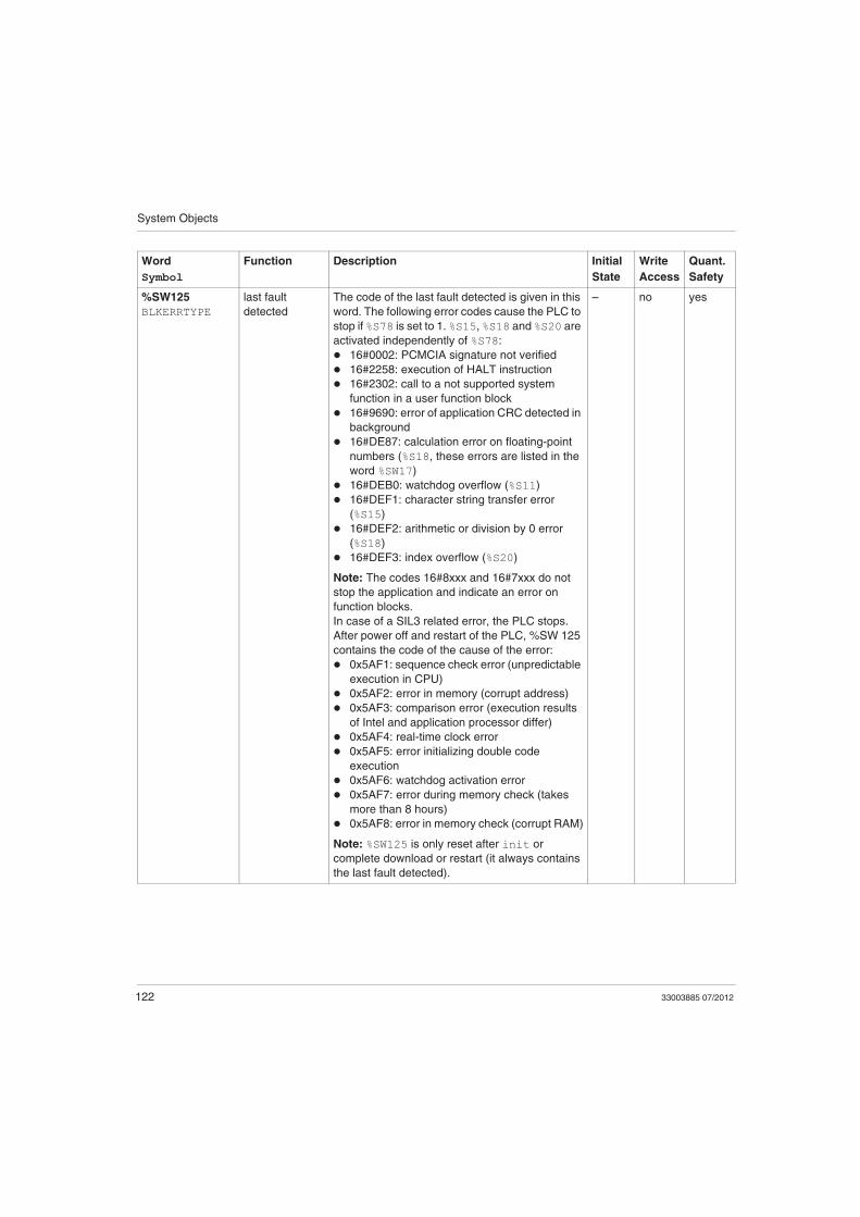
%SW125
BLKERRTYPE
last fault
detected
The code of the last fault detected is given in this
word. The following error codes cause the PLC to
stop if %S78 is set to 1. %S15, %S18 and %S20 are
activated independently of %S78:
16#0002: PCMCIA signature not verified
16#2258: execution of HALT instruction
16#2302: call to a not supported system
function in a user function block
16#9690: error of application CRC detected in
background
16#DE87: calculation error on floating-point
numbers (%S18, these errors are listed in the
word %SW17)
16#DEB0: watchdog overflow (%S11)
16#DEF1: character string transfer error
(%S15)
16#DEF2: arithmetic or division by 0 error
(%S18)
16#DEF3: index overflow (%S20)
Note: The codes 16#8xxx and 16#7xxx do not
stop the application and indicate an error on
function blocks.
In case of a SIL3 related error, the PLC stops.
After power off and restart of the PLC, %SW 125
contains the code of the cause of the error:
0x5AF1: sequence check error (unpredictable
execution in CPU)
0x5AF2: error in memory (corrupt address)
0x5AF3: comparison error (execution results
of Intel and application processor differ)
0x5AF4: real-time clock error
0x5AF5: error initializing double code
execution
0x5AF6: watchdog activation error
0x5AF7: error during memory check (takes
more than 8 hours)
0x5AF8: error in memory check (corrupt RAM)
Note: %SW125 is only reset after init or
complete download or restart (it always contains
the last fault detected).
– no yes
Word
Symbol
Function Description Initial
State
Write
Access
Quant.
Safety

System Objects
33003885 07/2012 123
For the description of the system words %SW128 to %SW339 and %SW535 to %SW640,
see the chapter "Quantum Specific System Words" (see Unity Pro, Program
Languages and Structure, Reference Manual ) in the Unity Pro Program Languages
and Structure Reference Manual. The system words %SW340 to %SW534 are not
used in Quantum Safety PLCs.
%SW126
ERRADDR0
%SW127
ERRADDR1
blocking fault
instruction
address
Address of the instruction that generated the
application blocking fault.
For 16 bit processors:
%SW126 contains the offset for this address,
%SW127 contains the segment number for this
address.
For 32 bit processors:
%SW126 contains the least significant word for
this address,
%SW127 contains the most significant word for
this address.
The content of %SW126 and %SW127 is for
Schneider Electric use only.
0 no yes
Word
Symbol
Function Description Initial
State
Write
Access
Quant.
Safety