
System ManualSmartIntego - ARAS
38
System Manual SmartIntego 09.2015
Transcript of System ManualSmartIntego - ARAS

System ManualSmartIntego
09.2015

Inhaltsverzeichnis1 Important.......................................................................................................................................... 3
2 Introduction ..................................................................................................................................... 4
3 System requirements...................................................................................................................... 5
4 Software installation and configuration........................................................................................ 64.1 Installation and configuration of the TCP/IP settings.............................................................. 64.2 Programming device driver installation .................................................................................. 94.3 SmartIntego software installation and configuration............................................................... 9
4.3.1 Installing the SmartIntego software ................................................................................ 94.3.2 Create new project.......................................................................................................... 94.3.3 Card configuration: unique ID ....................................................................................... 114.3.4 Card configuration: Mifare Classic................................................................................ 124.3.5 Card configuration: Mifare DESfire ............................................................................... 134.3.6 Radio network configuration ......................................................................................... 14
5 SmartIntego Manager ................................................................................................................... 235.1 Network ID............................................................................................................................ 235.2 Save button .......................................................................................................................... 235.3 Radio channel ...................................................................................................................... 235.4 SmartIntego Manager........................................................................................................... 235.5 Select GatewayNode............................................................................................................ 245.6 Add GatewayNode ............................................................................................................... 255.7 WaveNet statistics................................................................................................................ 255.8 Network mask....................................................................................................................... 265.9 GN_U(X), GN_ER – Administration ..................................................................................... 265.10 GN_U(X), GN_ER – Maintenance........................................................................................ 285.11 LockNode administration...................................................................................................... 30
6 Resetting GatewayNodes............................................................................................................. 336.1 SmartIntego Manager configurations of GatewayNodes only .............................................. 336.2 SmartIntego Manager configuration of GatewayNodes ....................................................... 336.3 Resetting the TCP/IP configuration GN.ER.......................................................................... 33
7 Connecting RS485, SI.GN.CONFIG.UC & SI.GN.CR................................................................... 34
8 Resetting locking devices............................................................................................................ 35
9 Additional information.................................................................................................................. 36
10 Declaration of Conformity ............................................................................................................ 37
11 Help & contact for SmartIntego ................................................................................................... 38
System ManualSmartIntego
2 / 38SimonsVoss Inhaltsverzeichnis

System ManualSmartIntego
3 / 38SimonsVoss 1 | Important
1 ImportantSimonsVoss Technologies GmbH reserves the right to modify the productwithout prior notification. As a result, the descriptions and images in thismanual may differ from the latest version of the product or software. TheGerman version of this manual takes precedence in cases of doubt. Errorsand spelling mistakes excepted.You can find more information about SimonsVoss products at:www.simons-voss.comAccess through a door may be denied if components are installed orprogrammed incorrectly. SimonsVoss Technologies GmbH is not liable forthe consequences of incorrect installation, such as denied access to injuredpersons or those at risk, physical damage or any other losses.People who have electronic, medical implants such as pacemakers andhearing aids must maintain a minimum distance of 30 cm between theimplant and network components and should be expressly informed of thisrequirement. In the interests of safety, people wearing electronic implantsshould seek medical advice regarding the potential hazards of radiocomponents (868/915 MHz).Read through all manuals for the individual SmartIntego componentscarefully.
System ManualSmartIntego
4 / 38SimonsVoss 2 | Introduction
2 IntroductionYou can use the SimonsVoss SmartIntego Manager to set up radio and/orcable networks on your own accord. You must have extensive knowledgeof the SmartIntego Tool application software, WaveNet technology and theSV hardware components. Knowledge of IT administration ( TCP/IP, LAN /WAN and COM ports) is required.SmartIntego Manager provides automatic addresses (hex address) for allnetwork nodes in a SimonsVoss radio/cable network. A scan will detect anynetwork nodes already installed. Each component sends a feedback signalwith its chip ID to SmartIntego Manager. A network structure is then formedin SmartIntego Manager and the automatically generated hex addressesand chip IDs are displayed. This structure (= topology [hex address]) isavailable as an exported .csv file after SmartIntego Manager is closed. Theradio frequency for Europe and Asia is 868 MHz. 9 different radio channelsare available for use.Note down the associated chip ID for the installation location, so that youcan identify where the different network nodes are located.Remember that precise documentation and a data backup need to bemaintained on a continuous basis to ensure stable operation.
System ManualSmartIntego
5 / 38SimonsVoss 3 | System requirements
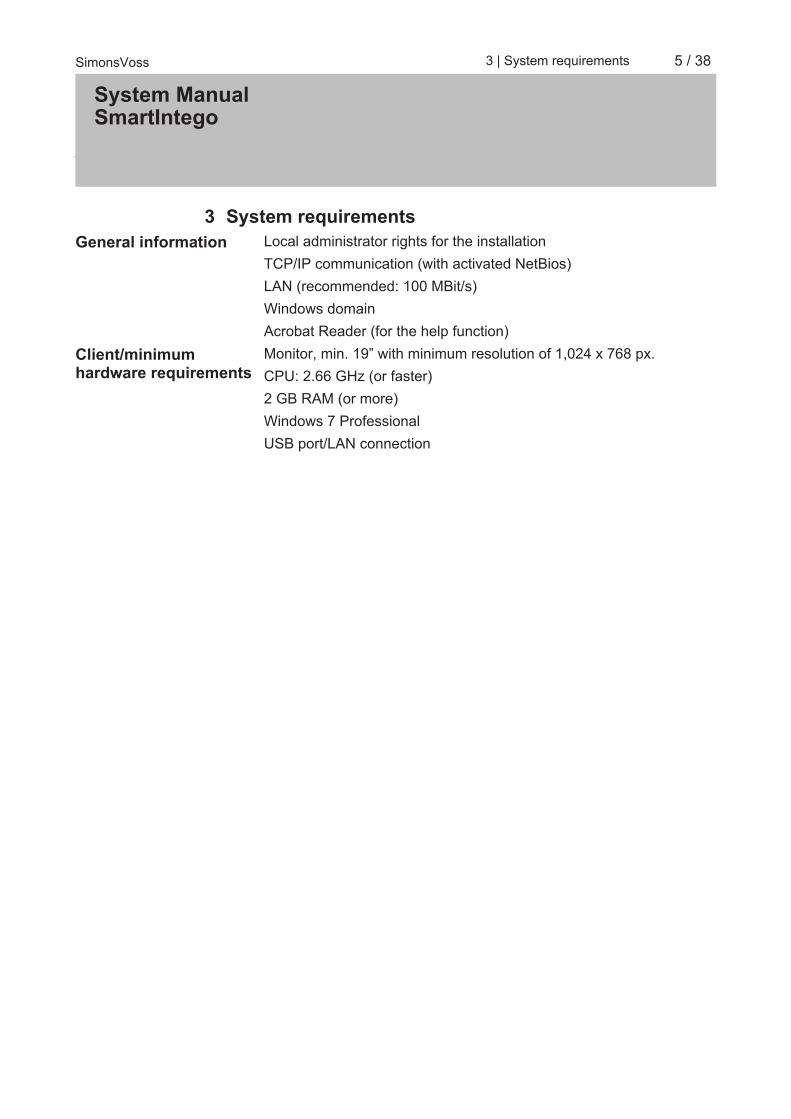
3 System requirementsGeneral information Local administrator rights for the installation
TCP/IP communication (with activated NetBios)LAN (recommended: 100 MBit/s)Windows domainAcrobat Reader (for the help function)
Client/minimumhardware requirements
Monitor, min. 19” with minimum resolution of 1,024 x 768 px.CPU: 2.66 GHz (or faster)2 GB RAM (or more)Windows 7 ProfessionalUSB port/LAN connection

System ManualSmartIntego
6 / 38SimonsVoss 4 | Software installation and configuration
4 Software installation and configuration
4.1 Installation and configuration of the TCP/IP settingsInstallation instructions for SmartIntego GatewayNode for TCP/IP networksettings using Digi Device Discovery
Installation of DigiDevice Discovery
1. Insert the CD supplied with the GatewayNode into the CD drive.2. Select the language that you require.3. Open the 'Discovery Tool' folder.4. Run the application as an administrator. (Right-click on 'Run as
administrator')5. Follow the installation steps.
ð After installation is complete, the system displays the message'Digi Device Discovery has now been successfully installed'.
Configuration of DigiDevice Discovery
1. Launch the Digi Device Discovery application that you have justinstalled.
ð
2. Select the corresponding IP address and click on 'Open webinterface'.
NOTICE You must always start in the same subnet whenever you work with this ap-plication to ensure that you can establish a connection with the device andcan change/configure TCP/IP network settings.

System ManualSmartIntego
7 / 38SimonsVoss 4 | Software installation and configuration
ð
3. Log on. The default log-on credentials are 'root' for the user name and'dbps' for the password.
ð
4. Navigate to Configuration/Network.

System ManualSmartIntego
8 / 38SimonsVoss 4 | Software installation and configuration
ð
NOTICE Once there, you can configure your IP settings. The configuration is set toDHCP by default. Once you have implemented changes, click on 'Apply' toaccept the changes that you have made. Log out when you have com-pleted the configuration.This application uses Port 2101 to communicate. Ensure that this port isalso open during the browser session.
5. Click on the 'Advanced network settings' if you wish to edit them.
ð
NOTICE This is where you can add the chip ID on the GatewayNode device as thehost name, e.g. DEFB. Click on 'Apply'.
6. Close the web interface.ð You should now return to the Digi Device Discovery application.ð You will now be able to see the GatewayNode's TCP/IP settings and
chip ID.7. Use the same procedure to set up any other GatewayNodes.

System ManualSmartIntego
9 / 38SimonsVoss 4 | Software installation and configuration
4.2 Programming device driver installation
NOTICE You must ensure that the card programming device remains connected tothe SmartIntego software via the USB port during the entire configurationand programming process.
1. Connect the programming device to your computer.2. Run the driver application, which you will find labelled as 'CardDriver
in the SmartIntego installation folder.ð The message 'Installation completed successfully' will be displayed
once installation is complete.
4.3 SmartIntego software installation and configuration
4.3.1 Installing the SmartIntego softwareInstall the latest version of the SmartIntego software.
4.3.2 Create new project1. Run SmartIntego software as an administrator.
ð A wizard to create a new project will launch automatically.
ð

System ManualSmartIntego
10 / 38SimonsVoss 4 | Software installation and configuration
2. 'Project - name': Enter project name (example: SmartIntego for systemintegration).
3. 'Project - password': enter the password that you want to use toprotect the project.
4. 'Project - confirm password': re-enter the password to check.5. 'Locking system - password': enter the password which will be
programmed into all devices.6. 'Locking system - confirm password': re-enter the password to check.
NOTICE The 'Project - password' and the 'Locking system - password' must be dif-ferent from one another and must each consist of 8 characters.
NOTICE Activate 'Open this project as default' checkbox to open this projectwhenever you launch SmartIntego software.
7. Press 'OK' to continue.
ð
8. Save .ikp file: we recommend saving the .ikp file in the SmartIntegoinstallation directory.

System ManualSmartIntego
11 / 38SimonsVoss 4 | Software installation and configuration
ð
4.3.3 Card configuration: unique IDClick on 'Card config (CardCfg_0001)' to configure your cards (cardconfiguration).ID: not configurableName: not configurableReturn timeout: e.g. 10 --> 1 /10 = 1 sec.Unique ID: activate the checkbox if a unique ID is being used. If youdeactivate the checkbox, the configuration for MIFARE/MIFARE DESFirewill appear.Card setups: if a UID (unique ID) is selected, the checkboxes for the cardsettings are greyed out.

System ManualSmartIntego
12 / 38SimonsVoss 4 | Software installation and configuration
4.3.4 Card configuration: Mifare ClassicClick on 'Card config (CardCfg_0001)' to configure your cards (cardconfiguration).ID: not configurableName: not configurableReturn timeout: e.g. 10 --> 1 /10 = 1 sec.Unique ID: If you deactivate the checkbox --> the configuration for MIFARE/MIFARE DESFire will appear.Card setups: you can configure up to five different MC/MD card settings.ID: not configurableName: configurableDelay: via radio (bytes): configurableLength remote (bytes): configurableDelay: local operation (bytes): configurableLength local (bytes): configurableRed-highlighted areas indicate missing or incorrect information.

System ManualSmartIntego
13 / 38SimonsVoss 4 | Software installation and configuration
Please note: the system integrator must enter the card parameters.
4.3.5 Card configuration: Mifare DESfireClick on 'Card config (CardCfg_0001)' to configure your cards (cardconfiguration).ID: not configurableName: not configurableReturn timeout: e. g. 10 --> 1 /10 = 1 sec.Unique ID: If you deactivate the checkbox --> the configuration for MIFARE/MIFARE DESFire will appear.Card setups: you can configure up to five different MC or MD card settings.ID: not configurableName: configurableDelay: via radio (bytes): configurableLength remote (bytes): configurableDelay: local operation (bytes): configurableLength local (bytes): configurableRed-highlighted areas indicate missing or incorrect information.Please note: the system integrator must enter the card parameters.

System ManualSmartIntego
14 / 38SimonsVoss 4 | Software installation and configuration
4.3.6 Radio network configuration1. Click on Tools/SmartIntego Manager to launch SmartIntego Manager
and configure the radio network settings.2. Enter the password for network components.
NOTICE Keep this password in a secure place. SimonsVoss Technologies GmbH isunable to restore the password if it is lost.
3. Right-click on 'WaveNet_11_5'.

System ManualSmartIntego
15 / 38SimonsVoss 4 | Software installation and configuration
ð
4. Select 'Add: CN_U(X), CN_S(X), RN_E(X) or RN_W(X)' to add aGatewayNode to SmartIntego Manager and then click on 'OK'.
ð
5. Click on 'Add IP or USB routers' and 'IP address' and enter theaddress for the GatewayNode.

System ManualSmartIntego
16 / 38SimonsVoss 4 | Software installation and configuration
ð
6. Network ID: e.g. the software randomly selects 4780 as the networkID. Used in conjunction with the password, this network ID provides aunique designation for your radio network.
ð
7. This is where you can select the frequency of your radio network.Ensure that no other devices use the same frequency since this canaffect the performance of all associated networks. Calculating thefrequency: 868.1 MHz+n*0.2 (n=1,2,...9)

System ManualSmartIntego
17 / 38SimonsVoss 4 | Software installation and configuration
ð
8. Network mask: you must select the 11_5 network mask forSmartIntego. Click on 'Yes' to add this node. This option is no longeravailable once the settings have been made. It will not appear againuntil you reset or delete all devices and set up a new radio network.
ð
9. The window displays the successfully configured GatewayNode.Right-click to select the GatewayNode (GN).

System ManualSmartIntego
18 / 38SimonsVoss 4 | Software installation and configuration
ð
10. Enter the name to describe the door (e.g. main entrance). Select 'Findchip ID' and click on 'OK'.

System ManualSmartIntego
19 / 38SimonsVoss 4 | Software installation and configuration
ð
11. Enter the chip ID featured on the label on the locking cylinderpackaging or inside the SmartHandle packaging --> e.g. 2d2 and theID to be assigned to the GatewayNode and click on 'Start'.
ð
12. Select the input and click on 'OK'.

System ManualSmartIntego
20 / 38SimonsVoss 4 | Software installation and configuration
ð
13. The image shows a successfully configured segment. Use the sameprocedure for any other devices. Click on 'Save' to continue once allnodes have been configured successfully.

System ManualSmartIntego
21 / 38SimonsVoss 4 | Software installation and configuration
ð
14. After you click on 'Exit', another screen is shown.
ð

System ManualSmartIntego
22 / 38SimonsVoss 4 | Software installation and configuration
15. Click on Locks --> Lock (Main Entrance) | ID: not configurable | Name:configurable | Address: not configurable | Chip ID: not configurable |Version: not configurable | SID (System ID)/LID (Lock ID): notconfigurable | PHI (Physical Hardware Identifier): not configurable |Time-controlled return function (Scandinavian FireMode): if youactivate the checkbox, the lock remains engaged ready for use for aspecific period of time --> disengages after a pre-set interval or doublebatch processing with an authorised card. | Status: programmingprompt --> locking device/locking devices need programming | Status:OK --> no further measures required | Read: read lock using wirelessconnection | Programme: programme lock via wireless connection |Reset: reset lock to default settings via wireless connection
ð
16. You need to click on 'Read' first if you would like to programme anunprogrammed lock. Then run 'Program' (top, right-hand corner). Theunique chip ID is also printed on the SI product.
ð

System ManualSmartIntego
23 / 38SimonsVoss 5 | SmartIntego Manager
5 SmartIntego Manager
5.1 Network IDThe default network ID is: DDDD (standard). All unprogrammedSmartIntego Manager components have this network ID. A new network IDmust be assigned manually at a later stage. The flash icon (shown below)indicates that it was not possible to complete the configuration for thecomponents concerned in this segment.
5.2 Save buttonClick on the 'Save' button if you have made any changes. AllGatewayNodes and LockNodes will receive their configuration once you doso.
5.3 Radio channelAll unprogrammed SmartIntego Manager components have a defaultfrequency (default radio channel). A different radio channel must beassigned manually at a later stage. The default radio channel is alwaysused in addition to the radio channel selected manually. This enables newcomponents to be added to existing WLAN networks. As a result, signalscan be sometimes transmitted on two different frequencies. Only onefrequency is used during normal operations.
5.4 SmartIntego ManagerYou can open administration by double-clicking or right-clicking onWaveNet in SmartIntego Manager.

System ManualSmartIntego
24 / 38SimonsVoss 5 | SmartIntego Manager
Update topology: automatic configuration of the whole network followed by messagesin SmartIntego Manager with an hexadecimal address and chip ID forall network nodes/components reached. This can take severalminutes, depending on the size.
Optimised: if the 'Optimised' setting is used, a search is initiated for both newnodes and previously configured nodes. You can move configurednodes (from other segments) to other segments to improveavailability. The system will search for new nodes if this setting is notused.
Find GN_U(X), GN_ER: the search is for these components only. Search for chip ID: You canuse the chip ID to look for a specific component anywhere in thenetwork/topology.
5.5 Select GatewayNodeIf you select 'Update topology' or 'Search for chip ID', you can implementthe function in the selected master segment concerned.

System ManualSmartIntego
25 / 38SimonsVoss 5 | SmartIntego Manager
5.6 Add GatewayNodeAdd GN_U(X), GN_ER: these components are directly added to thetopology via a COM port or using the IP address.
5.7 WaveNet statisticsDisplays all configured SmartIntego Manager components.

System ManualSmartIntego
26 / 38SimonsVoss 5 | SmartIntego Manager
A network ID must be entered if a new network needs to be identified orgenerated. The characters 0, 1, 2, 3, 4, 5, 6, 7, 8, 9, A, B, C, D, E and F arepermitted with a maximum length of four characters. The addresses 0000,0001, DDDD and FFFF are not permitted as a network ID. You also need toselect a radio frequency. Channels 1-9 and 11-15 are available for thispurposes. Channels 11 and 12 are special frequencies which are used inHong Kong and Malaysia, but they can also be used in Europe.
5.8 Network mask– 8_8 --> max. 249 GatewayNodes and max. 249 doors (per
GatewayNode)– 11_5 --> max. 1,700 GatewayNodes and max. 25 doors (per
GatewayNode)– 12_4 --> max. 3,200 GatewayNodes and max. 9 doors (per
GatewayNode)If you click on 'Yes' to close the dialogue, the network ID and the radiofrequency are programmed into the new components. This dialoguewindow is not displayed for existing networks.
5.9 GN_U(X), GN_ER – AdministrationYou can open administration by double-clicking or right-clicking on aGatewayNode in SmartIntego Manager.

System ManualSmartIntego
27 / 38SimonsVoss 5 | SmartIntego Manager
– Name:this is where you can enter the name of the GatewayNode.
– Replace with chip ID:If you wish to replace a component, you can enter the chip ID to add thenew component to the selected segment. The configuration is thentransmitted to the new network nodes. Please note: if a programmingflash icon is displayed for a component, you can try to programme anew configuration which will be added to the selected master segmentwithout changing the chip ID.
– Reset/delete:the selected components are reset and then deleted from theSmartIntego Manager screen. The components then feature the defaultconfiguration (default network ID: DDDD/Radio channel: default). ALockNode may not be reset until all locking devices have been reset.
– Move to another master segment:not possible for GNs.

System ManualSmartIntego
28 / 38SimonsVoss 5 | SmartIntego Manager
5.10 GN_U(X), GN_ER – Maintenance– Search master segment:
– Search results:creates an overview + possible configuration in this master segment.
The three columns describe and evaluate the nodes using RSSI whichare available in the selected master segment. The RSSI value for wiredsegments is always 0 (zero).– Nodes in this Segment:
this column displays all nodes which the previously selected mastersegment manages.
– Nodes in other segments:this column displays all nodes from which the master segmentdetects radio signals which, however, do not belong to the mastersegment. The nodes in this master segment can be assigned by

System ManualSmartIntego
29 / 38SimonsVoss 5 | SmartIntego Manager
highlighting them and dragging them to this first column (Nodes inthis segment). It may take a few seconds or minutes to assign themas the routing table needs to be updated.
– New nodes:this column displays all nodes which have not yet been assigned toa master segment. The nodes in this master segment can beassigned by double-clicking or highlighting them and dragging themto this first column (Nodes in this segment). It may take a fewseconds or minutes to assign them as the routing table needs to beupdated.
– RSSI (dBm):Received Signal Strength Indication = strength of the received signal--> an indicator of the received field strength. The more negative thedisplayed dBm value is, the poorer the quality that you can expectfrom the connection.
– Update branch:unprogrammed components are automatically integrated into thebranch based on their RSSI value.
– Optimised:if the 'Optimised' setting is used, a search is initiated for both newnodes and previously configured nodes. You can move configurednodes (from other segments) to other segments to improveavailability. The system will look for new nodes if this setting is notused.Search for chip ID:
This is where you can look for a chip ID. A new window will open assoon as you have entered the chip ID.

System ManualSmartIntego
30 / 38SimonsVoss 5 | SmartIntego Manager
You can select which master segment is to be searched. You canselect more than one segment. The entire network is searched if youselect 'All'.
– Ping:an availability test is carried out for selected components.
– Reboot:the selected components are rebooted.
5.11 LockNode administrationYou can open administration by double-clicking or right-clicking on a'LockNode' in SmartIntego Manager.

System ManualSmartIntego
31 / 38SimonsVoss 5 | SmartIntego Manager
– Name:this is where you can enter the name of the door.
– Replace with chip ID:if you wish to replace a component, you can enter the chip ID to add thenew component to the selected segment. The configuration is thentransmitted to the new network nodes. If a programming flash icon isdisplayed for a component, you can try to programme a newconfiguration which will be added to the selected master segmentwithout changing the chip ID.
– Reset/delete:the selected components are reset and then deleted from theSmartIntego Manager screen. The components then feature the defaultconfiguration (default network ID: DDDD/Radio channel: default)
– Move to another master segment:

System ManualSmartIntego
32 / 38SimonsVoss 5 | SmartIntego Manager
As a general rule: the more negative the RSSI value, the worse theconnection quality is. You can click on the LN_(X) to move it to anothersegment. The routing table is updated automatically if routers areadded.

System ManualSmartIntego
33 / 38SimonsVoss 6 | Resetting GatewayNodes
6 Resetting GatewayNodes
6.1 SmartIntego Manager configurations of GatewayNodes only1. Pull out the power plug.2. Wait about 20 seconds.3. Remove the cover (4 screws).4. Press on the button on the circuit board, near the power supply socket,
and keep it pressed down.5. Re-insert the power plug.6. Release the button when the red LED lights up (after about two
seconds).7. The SmartIntego Manager configuration has been reset (default
setting).
6.2 SmartIntego Manager configuration of GatewayNodesAll SmartIntego Manager settings are reset to their default values if apreviously configured LockNode is linked to another locking component in alocking system with a different locking system ID. The locking device whichneeds resetting needs to be reprogrammed and become part of a differentlocking system. You cannot use an unprogrammed locking device (lockingsystem ID = 0 [zero]).
6.3 Resetting the TCP/IP configuration GN.ER1. Pull out the power plug.2. Wait about 20 seconds.3. Remove the cover (4 screws).4. Press on the button on the circuit board, near the power supply socket,
and keep it pressed down.5. Re-insert the power plug.6. Hold the button down until the red and green LEDs flash alternately.7. Then release the button.8. The TCP/IP configuration has been deleted.

System ManualSmartIntego
34 / 38SimonsVoss 7 | Connecting RS485, SI.GN.CONFIG.UC & SI.GN.CR
7 Connecting RS485, SI.GN.CONFIG.UC & SI.GN.CR

System ManualSmartIntego
35 / 38SimonsVoss 8 | Resetting locking devices
8 Resetting locking devices1. Select the locking device concerned in the SmartIntego configuration
software.2. Click on the 'Reset' button. A yellow programming prompt is displayed
if the reset was successfully completed.3. Launch SmartIntego Manager to reset or delete the LockNode (Reset/
Delete).

System ManualSmartIntego
36 / 38SimonsVoss 9 | Additional information
9 Additional information– Chip ID:
indicated on the packaging label --> locking device/GatewayNodeThe packaging also contains an extra sticker for your documentation.
– PHI:indicated on the packaging label --> locking device + locking cylinderhousing

System ManualSmartIntego
37 / 38SimonsVoss 10 | Declaration of Conformity
10 Declaration of ConformityYou can access documents such as declarations of conformity and othercertificates online at www.smartintego.com.

System ManualSmartIntego
38 / 38SimonsVoss 11 | Help & contact for SmartIntego
11 Help & contact for SmartIntegoInstruction manuals You will find detailed information on operation and configuration
online on our homepage at www.smartintego.comat INFOCENTRE > PARTNER AREA > DOCUMENTATION
SimonsVoss Technologies GmbHFeringastrasse 485774 UnterföhringGermany


