
System Manual Safety System MGB-AR in combination with … · System Manual Safety System MGB-AR in...
28
More than safety. System Manual Safety System MGB-AR in combination with an interlocking module MGB-L0-AR-... (without guard locking)
Transcript of System Manual Safety System MGB-AR in combination with … · System Manual Safety System MGB-AR in...

More than safety.
System ManualSafety System MGB-AR
in combination with an interlocking module
MGB-L0-AR-...(without guard locking)

System Manual Safety System MGB-AR in Combination with an Interlocking Module
�
ContentsCorrect Use 3
Exclusion of Liability and Warranty 4
General Safety Instructions 4
Function 5
System overview 6Interlocking module MGB-L0-AR-... 6Handle module MGB-H-... 6Escape release MGB-E-... (optional) 6Dimension drawing 7
Lockout mechanism 8
Escape release (optional) 8
Installation 10
Changing Actuating Direction for Doors Hinged on the Left 11
Protection Against Environmental Effects 12
Electrical Connection 13Safety in case of faults 14Fuse protection for power supply 14Requirements for connection cables 14Notes on cable laying 15Pin assignment and contact description 16Operation as separate device 17Operation in a CES-AR switch chain 18Information on operation in a CES-AR switch chain 19
Setup 20Teach-in operation �0
System Status Table 22
Technical Data 23Typical system times �4
Inspection and Service 25
Declaration of Conformity 26

System Manual Safety System MGB-AR in Combination with an Interlocking Module
�
Correct UseThe safety system MGB is an electromagnetic interlock device without guard locking.
The system comprises at least one interlocking module MGB-L0-AR-... and one handle module MGB-H...
The interlocking module MGB-L0-AR-... can be integrated into a switch chain for the safety system CES-AR or operated as a separate system.
In combination with a separating safety guard, this safety component prevents dangerous machine movements from being performed for as long as the safety guard is open. A stop command is triggered if the safety guard is opened during the dangerous machine function.
For the control system, this means that
starting commands which cause hazardous situations must become active only when the safety guard is in the protective position.
Before safety components are used, a risk assessment must be performed on the machine in accordance with
EN ISO 1�849-1, Safety of machinery. Safety related parts of control systems. General principles for design, Annex B
EN ISO 141�1, Safety of machinery. Risk assessment. Principles.
Correct use includes compliance with the relevant requirements for installation and operation, in particular
EN ISO 1�489-1, Safety of machinery. Safety related parts of control systems. General principles for design
EN 1088, Safety of machinery. Interlocking devices associated with guards. Principles for design and selection
EN 60�04-1, Safety of machinery. Electrical equipment of machines. General requirements.
The safety system MGB can only be combined with the intended modules in the MGB system family.
On the modification of system components, EUCHNER provides no warranty for safe function.
Connection of several devices in a CES-AR switch chain is permitted only using devices intended for series connection with the CES-AR. Please check this in the operating instructions of the respective device. For detailed information on opera-tion in a CES-AR switch chain, please see the related CES-AR system manual.
Important!
The user is responsible for safe integration of the device in a safe overall system. For this purpose the overall system must be validated, e.g. in accor-dance with EN ISO 1�849-�.The permissible operating parameters must be observed for correct use (see Technical data).If a product data sheet is included with the product, the information on the data sheet applies in case of discrepancies with the operating instructions.

System Manual Safety System MGB-AR in Combination with an Interlocking Module
4
Important!
In the estimation of the PL for the overall system, a maximum value of 100 years can be assumed for the MTTFd according to the limit value in EN ISO 1�849-1:�008, Section 4.5.�. This corresponds to a minimum value for the PFHd of �.47 x 10-8/h.When up to 10 devices are connected in series, these limit values can be assumed for the entire switch chain as a subsystem. As a subsystem, this switch chain achieves PL e.
Exclusion of Liability and WarrantyIn case of failure to comply with the conditions for correct use stated above, or if the safety instructions are not followed, or if any servicing is not performed as required, liability will be excluded and the warranty void.
General Safety InstructionsSafety switches fulfill personal protection functions. Incorrect installation or tamper-ing can lead to fatal injuries to personnel.
Check the safe function of the safety guard particularly
after any setup work
after the replacement of an MGB component
after an extended period without use
after every fault
Independent of these checks, the safe function of the safety guard should be checked at suitable intervals as part of the maintenance schedule.
Warning!
Loss of safety function in the event of incorrect connection or incorrect use. Safety switches must not be bypassed (bridging of contacts), turned away, removed or otherwise rendered ineffective.On this topic pay attention in particular to the measures for reducing the pos-sibility of bypassing from EN 1088:1995+A�:�008, section 5.7.The switching operation is only allowed to be triggered by the intended han-dle module MGB-H... that is positively fastened to the safety guard.
The device is only allowed to be installed and placed in operation by authorized personnel who are familiar with the correct handling of safety components who are familiar with the applicable EMC regulationswho are familiar with the applicable regulations on health and safety who have read and understood the operating instructions and the system manual
System Manual Safety System MGB-AR in Combination with an Interlocking Module
5
Important!
Prior to use read the operating instructions and the system manual, and keep these in a safe place. Ensure the operating instructions and the system manual are always available during mounting, setup and servicing. EUCHNER cannot provide any warranty in relation to the readability of the CD for the storage pe-riod required. For this reason you should archive a printed copy of the system manual. If you should lose the operating instructions or the system manual, you can download these documents from www.EUCHNER.de.
FunctionTogether with a handle module, the interlocking module makes it possible to interlock moveable safety guards. The combination also serves as a mechanical door stop at the same time.
The following switch-on condition applies for the safety outputs OA and OB (see also System status table):
Safety guard closed
Bolt tongue inserted in the interlocking module
Both safety inputs (IA and IB) must be on
The interlocking module detects the position of the safety guard and the position of the bolt tongue.
The bolt tongue in the handle module is extended and retracted into the interlocking module by actuating the door handle.
System Manual Safety System MGB-AR in Combination with an Interlocking Module
6
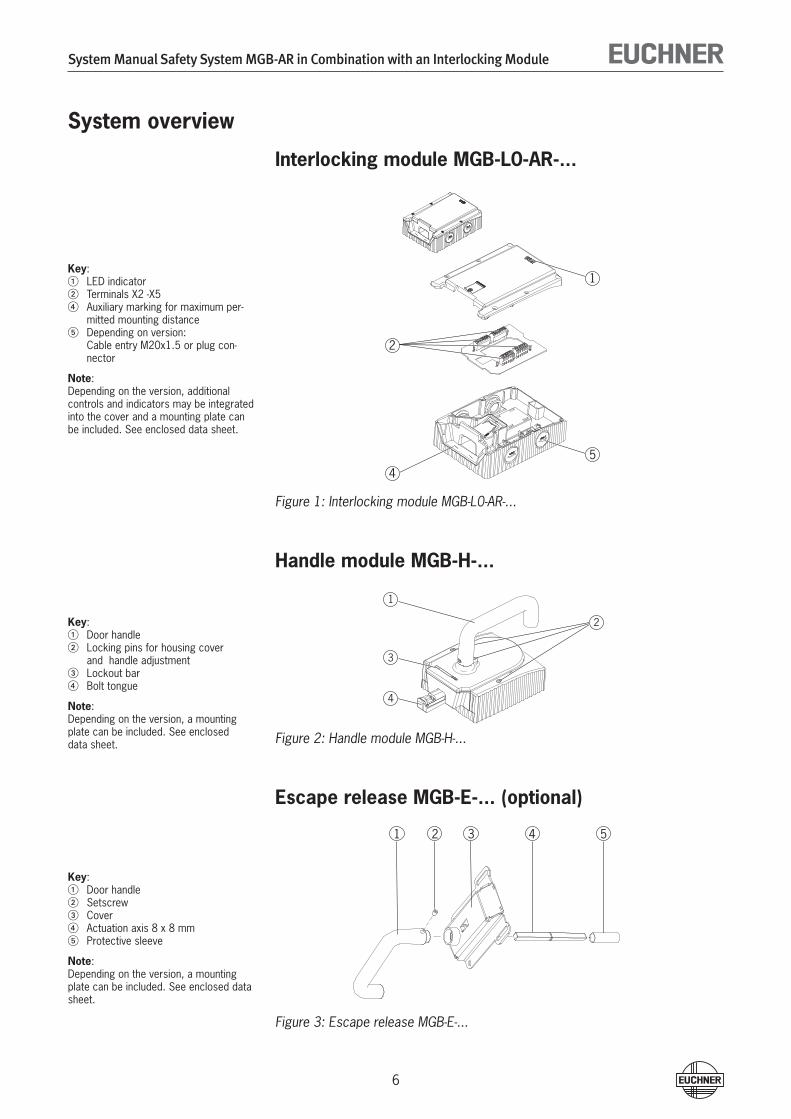
System overview
Interlocking module MGB-L0-AR-...
Figure 1: Interlocking module MGB-L0-AR-...
Handle module MGB-H-...
Figure 2: Handle module MGB-H-...
Escape release MGB-E-... (optional)
Figure 3: Escape release MGB-E-...
1
2
3
4
Key:1 Door handle2 Locking pins for housing cover
and handle adjustment3 Lockout bar4 Bolt tongue
Note: Depending on the version, a mounting plate can be included. See enclosed data sheet.
1 2 3 4 5
Key:1 Door handle2 Setscrew3 Cover4 Actuation axis 8 x 8 mm5 Protective sleeve
Note: Depending on the version, a mounting plate can be included. See enclosed data sheet.
1
4
2
5
Key:1 LED indicator2 Terminals X� -X54 Auxiliary marking for maximum per-
mitted mounting distance 5 Depending on version:
Cable entry M�0x1.5 or plug con-nector
Note: Depending on the version, additional controls and indicators may be integrated into the cover and a mounting plate can be included. See enclosed data sheet.

System Manual Safety System MGB-AR in Combination with an Interlocking Module
7
Dimension drawing
Figure 4: Dimension drawing, MGB fitted without optionial mounting plates
yx
z
5172
114
40
4093
113,5 110
M20x1,5 (4x)
19,2
289,3
AUFOPEN
CLOSEDZU
40
130
15
111
40
4
155,3
7,5
6,5
86,5
15,4
15
73,5
6,3
6,2
89
,4
245
10
46
10
89
,4
77
,5
92
,5
16,5
4010
58,5
110
8 x 8

System Manual Safety System MGB-AR in Combination with an Interlocking Module
8
Lockout mechanismIf the lockout bar is pivoted out, the bolt tongue cannot be extended. The lockout bar can be secured with padlocks (see Figure 5)
To pivot out, press the grooved part (only possible with bolt tongue retracted).
Figure 5: Lockout bar secured with padlock
Escape release (optional)The escape release is used to open a safety guard from the inside without tools.
Warning!
Loss of the safety function due to incorrect mounting of the escape release.
The actuation axis for the escape release must be inserted min. 10 mm into the handle module.
In case of profile widths larger than 40 mm and on the usage of mounting plates use �50 mm actuation axis (order no. 106 761) and cut to length.
In case of profile widths smaller than 40 mm, cut actuation axis and protective sleeve to length.
Align escape release axis at right angles to the handle module. See Figures 4 and 7.
Install escape release so that operation as well as inspection and maintenance are possible.
Key:1 Padlock ∅ min. � mm, ∅ max. 10
mm
Note: You can fit a maximum of � locks Ø 8 mm.
1Order No. 100464 Order No. 111157

System Manual Safety System MGB-AR in Combination with an Interlocking Module
9
Preparing the escape release
1 Fit door handle 2 Insert actuation axis. The locking ring A must be in contact with
the escape release B.3 Tighten setscrew to � Nm4 Fit protective sleeve
Figure 6: Preparing the escape release
1
3 24
A
B
Protective sleeveActuation axis
Example with mounting plates:
58,5
4
D
4
(10)
55,5
(+ 4
mm
per
pla
te)
250
182
Mounting plates
D +
13,
5
3,5
(+ 4
mm
per
pla
te)
D +
3

System Manual Safety System MGB-AR in Combination with an Interlocking Module
10
4x M6
2x M6
0,5 Nm
1 Nm (6x)
InstallationWarning!
Mounting must be performed only by authorized personnel.
For installation steps see Figure 7 and Figure 8 to 1�.
Install system so that
operation of the mechanical release as well as inspection and maintenance are possible.
Figure 7: Installation example for door hinged on the right (general view)
Fastening material not included!
Cut-out for escape release
Tightening torque 4 Nm

System Manual Safety System MGB-AR in Combination with an Interlocking Module
11
Changing Actuating Direction for Doors Hinged on the Left
Important!
It is only possible to make this change when the bolt tongue is not extended and an escape release is not yet mounted.
As supplied, the handle module is set for doors hinged on the right.
The safety guard opens by pressing down the door handle.
The system is mounted the other way up for doors hinged on the left.
The safety guard opens by pressing up the door handle (see Figure 8).
For this reason the actuating direction of the door handle must be changed (see Figure 8 - 1�).
CLOSED
OPEN1
3
2
4
5
4 Lift locking pin on the door handle using a screwdriver and hold in this position.
5 Turn door handle to right.
1 Push door handle upwards.2 Unscrew locking pins to the marking3 Push cover to the side.
7
a6
b
4 mm
8
6 Only on the usage of an escape release: Turn joint with hex screw counter-clockwise from position (a) to position (b).
7 Close cover.8 Screw in locking pins and tighten to � Nm.
Figure 8: Changing actuating direction, step 1 Figure 9: Changing actuating direction, step 2 and 3
Figure 10: Changing actuating direction, step 4 and 5 Figure 11: Changing actuating direction, step 6 to 8

System Manual Safety System MGB-AR in Combination with an Interlocking Module
1�
3 mm9
10
OPEN
CLOSED
9 Undo setscrew.AT Move door handle 90° clockwise and fasten again. Tighten setscrew to � Nm AK State after the change
Fig. 12: Changing actuating direction, step 9 and AT Figure 13: Changing actuating direction, final state
Protection Against Environmental EffectsLasting and correct safety function requires that the system must be protected against foreign bodies such as swarf, sand, blasting shot, etc., which can become lodged in the interlocking and handle modules. For this purpose a suitable instal-lation position should be selected.
Cover device during painting work!

System Manual Safety System MGB-AR in Combination with an Interlocking Module
1�
Electrical ConnectionWarning!
In case of an error, loss of the safety function through incorrect connection.To ensure safety, both safety outputs (OA and OB) must always be evaluated.The monitoring outputs O1 ... O4 must not be used as safety outputs.Lay the connection cables with protection to prevent the risk of short cir-cuits.
Caution!
Risk of damage to equipment or malfunctions as a result of incorrect connec-tion.Do not use a control system with pulsing or switch off the pulsing function in your control system. The device generates its own clock signal on the output lines OA/OB. A downstream control system must tolerate these test pulses, which may have a length of up to 1 ms. The pulses are also present when the safety outputs are switched off. De-pending on the inertia of the connected device (control system, relay, etc.), this can lead to short switching processes.The inputs on an evaluation unit connected must be positive-switching, as the two outputs on the safety switch deliver a level of +�4 V in the switched-on state.All the electrical connections must either be isolated from the mains supply by a safety transformer according to EN IEC 61558-�-6 with limited output voltage in the event of a fault, or by other equivalent isolation measures.For use and operation as per the requirements, a power supply with the feature "for use in class � circuits" must be used. The same requirement ap-plies to the safety outputs.Alternative solutions must comply with the following requirements:a) Electrically isolated power supply unit with a max. open-circuit voltage of �0
V/DC and a limited current of max. 8 A.b) Electrically isolated power supply unit in combination with fuse as per UL�48.
This fuse should be designed for max. �.� A and should be integrated into the �0 V/DC voltage section.
All electrical outputs must have an adequate protective circuit for inductive loads. The outputs must be protected with a free-wheeling diode for this pur-pose.Power devices which are a powerful source of interference must be installed in a separate location away from the input and output circuits for signal pro-cessing. The cable routing for safety circuits should be as far away as pos-sible from the cables of the power circuits.To prevent EMC problems, it is imperative you follow section Notes on cable laying, page 15.
Important!
If the device does not appear to function when operating voltage is applied (e.g. green DIA LED does not flash), the safety switch must be returned uno-pened to the manufacturer.To ensure the stated degree of protection IP67 is achieved, the cover screws must be tightened to a tightening torque of 1 Nm.Tighten screw for the cover for the mechanical release to 0.5 Nm.
System Manual Safety System MGB-AR in Combination with an Interlocking Module
14
Safety in case of faultsThe operating voltage UB is reverse polarity protected.
The contacts IA/IB and OA/OB are short circuit-proof
A short-circuit between IA and IB or OA and OB is detected by the switch.
A short circuit in the cable can be excluded by laying the cable with protection.
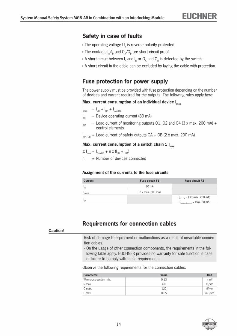
Fuse protection for power supplyThe power supply must be provided with fuse protection depending on the number of devices and current required for the outputs. The following rules apply here:
Max. current consumption of an individual device Imax
Imax = IUB + IUA + IOA+OB
IUB = Device operating current (80 mA)
IUA = Load current of monitoring outputs O1, O� and O4 (� x max. �00 mA) + control elements
IOA+OB = Load current of safety outputs OA + OB (� x max. �00 mA)
Max. current consumption of a switch chain Σ Imax
Σ Imax = IOA+OB + n x (IUB + IUA)
n = Number of devices connected
Assignment of the currents to the fuse circuits
Current Fuse circuit F1 Fuse circuit F2
IUB 80 mA
IOA+OB (� x max. �00 mA)
IUA
IO1...O4 = (� x max. �00 mA)
IControl elements = max. �0 mA
Requirements for connection cablesCaution!
Risk of damage to equipment or malfunctions as a result of unsuitable connec-tion cables.On the usage of other connection components, the requirements in the fol-lowing table apply. EUCHNER provides no warranty for safe function in case of failure to comply with these requirements.
Observe the following requirements for the connection cables:
Parameter Value Unit
Wire cross-section min. 0,1� mm²
R max. 60 W/km
C max. 1�0 nF/km
L max. 0,65 mH/km

System Manual Safety System MGB-AR in Combination with an Interlocking Module
15
Notes on cable layingLay all MGB connection cables in a common cable harness.
Important: lay cables in a common harness
Figure 14: Stipulate cable laying
PLC
+ 24 V DC
cabinet
0 V
MGB-L.-AR...
IA/IB OA/OB
UB 0V UA 0V

System Manual Safety System MGB-AR in Combination with an Interlocking Module
16
Pin assignment and contact description
Figure 15: Connections and LEDs
Terminal Designation Description
X�.1 to X�.� - See the enclosed data sheet
X�.4 UA Power supply for the monitoring outputs
X�.5 and X�.6 0V Ground for the power supply (connected internally to X5.5).Important: At least one of the two contacts must be connected to 0V.
X�.7 - Not used
X4.1 IA Enable input for channel A, connect to DC �4 V in separate opera-tion. In case of switch chains, connect output signal OA from previous device.
X4.� IB Enable input for channel B, connect to DC �4 V in separate opera-tion. In case of switch chains, connect output signal OB from previous device.
X4.� - Not used
X4.4 OA Safety output channel A,ON when the door is closed and the bolt tongue is inserted in the interlocking module.
X4.5 OB Safety output channel B,ON when the door is closed and the bolt tongue is inserted in the interlocking module.
X4.6 RST Reset input, device is reset if DC �4 V are applied to RST for at least � s.
X5.1 O1 Door monitoring output, ON when the door is closed.
X5.� O� Bolt tongue monitoring output,ON when the door is closed and the bolt tongue is inserted in the interlocking module.
X5.� - Not used
X5.4 O4 Monitoring output DIA�,ON when the device is in the fault state.
X5.5 0V Ground for power supply, DC 0 V (connected internally to X�.5 and X�.6)
X5.6 UB Power supply, DC �4 V
X�.1 to X�.7 - See the enclosed data sheet
Table 1: Pin assignment and contact description
42 63 51
11
42 63 51
2345
X3
X4 X5
X2
LEDDIA 1PowerDIA 2State
gngnrdye
7 6 2345 7 6

System Manual Safety System MGB-AR in Combination with an Interlocking Module
17
Operation as separate device
Figure 16: Connection example for separate operation
The switches can be reset via the RST input. To do this, a voltage of �4 V is ap-plied to the RST input for at least � seconds. The supply voltage to the switches is interrupted during this time. The RST input must be connected to 0 V if it is not used.
24V
GN
D
-F1
X5.6 UB
X5.5 0V
X5.4 OUT4
X5.3 OUT3
X5.2 OUT2
X5.1 OUT1
X4.6 RST MG
BLX4.5 OB
X4.4 OA
X4.3 ---
X4.2 IB
X4.1 IA
Entr
iege
ln/
Unlo
ck
X3.7 UCM
X3.6 0VM
X3.5 0VM-F2
X3.4 UA
A1
24VD
C
A1 A2
S11
S10
ESM
-BA3
xx
S13
EUC
HN
ERStar
t KA KB
S21
S12
K1+
S14
K2+
13 14
KAA1 A2
23 24
KBA1 A2
33 34
41 42

System Manual Safety System MGB-AR in Combination with an Interlocking Module
18
Operation in a CES-AR switch chain
Figure 17: Connection examples for operation in a CES-AR switch chain
For detailed information on operation in a CES-AR switch chain, see the related CES-AR system manual. The interlocking module MGB-L0-... behaves in the switch chain in practice like a safety switch CES-AR. The differences to the CES-AR are described in the following.
GN
D
DC
24
V
A1
24VD
C
F1
A1 A2
S11
S10
ESM
-BA3
xx
S13EU
CH
NER
S21
S12
K1
+
UB X5.6
0V X5.5
O4 X5.4
S14
K2
+O3 X5.3
O2 X5.2
O1 X5.1
F5
13 14
K5
RST X4.6
OB X4.5
MG
B-L
1-AR
...
#3
OA X4.4
F6
23 24
K6
NC X4.3
IB X4.2
IA X4.1
33 34
UCM X3.7
NC X3.6
41 42
0VM X3.5
F2
UA X3.4
UB X5.6
0V X5.5
O4 X5.4
O3 X5.3
O2 X5.2
O1 X5.1
RST X4.6
OB X4.5
MG
B-L
1-AR
...
#2
OA X4.4
NC X4.3
IB X4.2
IA X4.1
UCM X3.7
NC X3.6
0VM X3.5
-F3
ACH
TUN
G: R
ückf
ührk
reis
mus
s en
tspr
eche
nd R
isik
obeu
rtei
lung
ein
gebu
nden
wer
den.
UA X3.4
UB X5.6
0V X5.5
O4 X5.4
O3 X5.3
O2 X5.2
O1 X5.1
RST X4.6
OB X4.5
MG
B-L
1-AR
... #
1
OA X4.4
NC X4.3
IB X4.2
IA X4.1
UCM X3.7
NC X3.6
0VM X3.5
F4
UA X3.4
ATTE
NTI
ON
: Fee
dbac
k lo
op m
ust b
e in
tegr
ated
acc
ordi
ng to
ris
k as
sess
men
t.

System Manual Safety System MGB-AR in Combination with an Interlocking Module
19
Information on operation in a CES-AR switch chainSystem timesThe interlocking module has longer response times than a CES-AR switch (see Technical data and diagram of Typical system times, Figure 19 and �0).
Position in a CES-AR switch chainThe interlocking module must be the last device in the CES-AR switch chain (see Figure 18).
Important: lay cables in a common harness
Figure 18: Position in a CES-AR switch chain
Output currentThe safety outputs on the interlocking module have a lower maximum output cur-rent than a CES-AR switch (see Technical data).
Number of devices in the switch chainsIn a pure MGB switch chain a maximum of ten devices can be connected in series. In mixed switch chains (e. g. together with CES-AR) the maximum number of devices is also reduced to ten.
CES-AR
terminating plug
CES-AR
CES-AR
PLC
MGB-L.-AR...
+ 24 V DC
cabinet
0 V
IA/IB
IA/IB
OA/OB
OA/OB
IA/IB
IA/IB OA/OB
UB 0V UA 0V
OA/OB
#1
#2
#3
#4 MGB-L.-AR...
IA/IB OA/OB
UB 0V UA 0V
#5
System Manual Safety System MGB-AR in Combination with an Interlocking Module
�0
Setup
Teach-in operationThe handle module must be assigned to the interlocking module using a teach-in function before the system forms a functional unit.
During a teach-in operation, the safety outputs are in high-resistance state, i.e. the system is in the safe state.
Important!
The interlocking module disables the code for the previous handle module if teach-in is carried out for a new handle module. Teach-in is not possible again immediately for this module if a new teach-in process is carried out. The disabled code is deleted again in the interlocking module only after a third code has been taught.The interlocking module can only be operated with the last handle module taught.If the locking module detects the learned or a locked handle during learning readiness, the learning readiness is ended immediately and the locking mod-ule enters normal mode or indicates a fault.If the bolt tongue is in the operating distance for less than 60 s, the handle module is not taught.
Teaching in handle moduleFit handle module.
Close safety guard. Check for correct alignment and distance using the mark-ing on the interlocking module and re-adjust if necessary.
Insert bolt tongue in the interlocking module.
Apply operating voltage to the interlocking module.
The green LED (DIA1) flashes quickly (approx. 10 Hz)
A self-test is performed during this time (approx. 8 s). After this, the LED flashes cyclically three times and signals that it is in standby state for teach-in. Standby state for teach-in remains active for approx. � minutes.
Teach-in operation starts, green LED (DIA1) flashes slowly (approx. 1 Hz). Dur-ing teach-in, the interlocking module checks whether the handle module is a disabled handle module. Provided this is not the case, the teach-in operation is completed after approx. 60 seconds, and the green LED (DIA1) goes out. The new code has now been stored, and the old code is disabled.
To activate the handle module's code from the teach-in operation in the inter-locking module, the operating voltage must then be switched off at the inter-locking module for min. � seconds. As an alternative, �4V can be applied to the input RST for min. � seconds.
Mechanical function testIt must be possible to easily insert the bolt tongue in the interlocking module. To check, close safety guard several times and actuate door handle.
If available, check function of the escape release. It must be possible to operate the escape release from the inside without excessive effort.

System Manual Safety System MGB-AR in Combination with an Interlocking Module
�1
Electrical function test
Warning!
On usage in a CES-AR safety chain, also follow the procedure for the function check in the related CES-AR system manual.
Switch on operating voltage.
The interlocking module carries out a self-test. The green LED (DIA1) flashes for 8 s with 10 Hz.
Close all safety guards and insert the bolt tongue into the interlocking mod-ule.
The machine must not start automatically.
Enable operation in the control system.
Actuate the door handle.
The machine must switch off. The yellow LED (STATE) on the interlocking mod-ule flashes at regular intervals.
Open the safety guard. The yellow LED (STATE) goes out.
Close the safety guard again.
The machine must not start up again immediately.
Enable operation again in the control system.
Repeat steps �-6 for each safety guard.
1.
�.
�.
4.
4.
5.
6.

System Manual Safety System MGB-AR in Combination with an Interlocking Module
��
System Status TableO
pera
ting
mod
e
Guard position
Bolt tongue posi-tion
Safety outputs OA and OB
Door monitoring output
Bolt tongue moni-toring output
Monitoring output DIA 2
LED
dis
play
Stat
e
DIA 1 (green)
POWER
DIA 2 (red)
STATE (yel-low)
Self-
test
XX
off
off
off
off
10 H
z (8
s)
Self-
test
afte
r po
wer
-up
Nor
mal
ope
ratio
n
open
not i
n-se
rted
off
off
off
off
Nor
mal
ope
ratio
n, d
oor
open
clos
edno
t in-
sert
edof
fon
off
off
0.5
HzN
orm
al o
pera
tion,
doo
r cl
osed
clos
edin
sert
edon
onon
off
Nor
mal
ope
ratio
n, d
oor
clos
ed, b
olt t
ongu
e in
sert
ed
Teac
h-in
sta
ndby
st
ate
open
not i
n-se
rted
off
off
off
off
� x
Door
ope
n, u
nit i
s re
ady
for
teac
h-in
for
anot
her
hand
le m
odul
e (o
nly
shor
t tim
e af
ter
pow
er-u
p)
Setu
pcl
osed
inse
rted
off
off
onof
f�
HzTe
ach-
in o
pera
tion
XX
off
off
off
off
1 Hz
Posi
tive
ackn
owle
dgem
ent a
fter
com
plet
ion
of te
ach-
in o
pera
tion
Faul
t dis
play
XX
off
off
off
on�
xIn
put f
ault
(e.g
. mis
sing
test
pul
ses,
illo
gica
l sw
itch
stat
e fro
m n
ext s
witc
h)*
XX
off
off
off
on�
xHa
ndle
mod
ule
read
err
or (e
.g. f
ault
in c
ode
or c
ode
not r
eada
ble)
**
XX
off
off
off
on4
xO
utpu
t fau
lt (e
.g. s
hort
-circ
uit,
loss
of s
witc
hing
cap
abilit
y)*
XX
off
off
off
on5
xIn
tern
al fa
ult (
e.g.
com
pone
nt fa
ulty
, dat
a fa
ult)
or s
hort
circ
uit o
n th
e ou
tput
s*
XX
off
off
off
on6
xSi
gnal
seq
uenc
e er
rone
ous
***
Key
to s
ymbo
ls
LED
is n
ot li
t
LED
is li
t
10 H
z (8
s)
LED
flash
es fo
r 8
seco
nds
with
10
Hz
� x
LED
flash
es th
ree
times
XAn
y st
ate
* La
tchi
ng fa
ult;
to re
set u
se R
ST in
put o
r br
iefly
isol
ate
devi
ce fr
om th
e po
wer
sup
ply
**
Non
-latc
hing
faul
t; to
rese
t ope
n sa
fety
gua
rd a
nd c
lose
aga
in**
* La
tchi
ng fa
ult;
to re
set,
open
the
safe
ty d
oor
com
plet
ely,
then
inte
rrup
t the
pow
er s
uppl
y or
use
the
RST
inpu
t. Ap
prox
. 5 s
afte
r po
wer
up,
the
faul
t is
rese
t and
the
devi
ce o
pera
tes
in n
orm
al m
ode.
Impo
rtan
t: If
you
cann
ot fi
nd th
e di
spla
yed
devi
ce s
tatu
s in
the
syst
em s
tatu
s ta
ble,
this
indi
cate
s th
at th
ere
is a
n in
tern
al d
evic
e fa
ult.
In th
is c
ase,
you
sho
uld
cont
act t
he m
anuf
actu
rer.

System Manual Safety System MGB-AR in Combination with an Interlocking Module
��
Technical DataNote!
If a product data sheet is included with the product, the information on the data sheet applies in case of discrepancies with the operating instructions.
Parameter Value Unit
Housing material Glass fiber reinforced plastic die-cast zinc, nickel-plated
Stainless steel
Dimensions See dimension drawing
WeightInterlocking moduleHandle moduleEscape release
0,751,000,50
kg
Ambient temperature at UB = DC �4 V -�0 .... +55 °C
Degree of protection- on usage of key-operated switches
IP 54 IP 4�
Safety class III
Degree of contamination �
Installation position Any
Connection type 4 cable entries M�0x1.5 or plug connector RC18
Conductor cross-section (rigid/flexible)- with ferrule according to DIN 46��8/1- with ferrule with collar according to DIN 46��8/1
0.1� ... 1.5 (AWG �4 ... AWG 16)0.�5 ... 1.50.�5 ... 0.75
mm²
Auxiliary power monitoring outputs UA (reverse polarity protected, regulated, residual ripple < 5 %)
�4 +10% / -15% (PELV) V DC
Current consumption IUB (no load on any outputs) 80 mA
- Additional current consumption for version with controls and indicators in the cover
Max. �0 mA
External fuse See page 14 "Fuse protection for power supply"
Safety outputs OA/OB Semiconductor outputs, p-switching, short circuit-proof
Output voltage UOA/UOB 1)
HIGH UOA / UOB UB-�V ... UB
LOW UOA / UOB 0 ... 1 V DC
Switching current per safety output 1 ... �00 mA
Utilization category according to EN IEC 60947-5-�
DC-1� �4 V �00 mA Caution: outputs must be protected with a free-
wheeling diode in case of inductive loads.
Classification acc. to EN IEC 60947-5-� PDF-M
Monitoring outputs- Output voltage 1)
- Max. load
p-switching, short circuit-proofUA - �V ... UA
Max. �00 mA
Rated insulation voltage Ui �0 V
Rated impulse withstand voltage Uimp 1,5 kV
Resilience to vibration As per EN IEC 60947-5-�
Switching frequency 1 Hz
EMC protection requirements As per EN IEC 60947-5-�
Reliability figures according to EN ISO 13849-1
Category 4
Performance Level PL e
PFHd �.4 x 10-9 / h �)
Mission time �0 years1) Values at a switching current of 50 mA without taking into account the cable lengths.�) Applying the limit value from EN ISO 1�849-1:�008, section 4.5.� (MTTFd = max. 100 years), BG certifies a PFHd of max.
�.47 x 10-8.

System Manual Safety System MGB-AR in Combination with an Interlocking Module
�4
Typical system timesReady delayAfter switching on, the unit carries out a self-test for 8 s. The system is ready for operation only after this time.
Risk time according to EN 60947-5-3If the door handle is actuated, the safety outputs OA and OB on the interlocking module are deactivated after a maximum of �75 ms.
Difference timeThe safety outputs OA and OB switch with a minor time offset. They have the same signal state at the latest after a difference time of 10 ms.
Important!
The system times given are maximum values.
Figure 19: Typical system times for operation as a separate system
Figure 20: Typical system times for operation in a switch chain
t0
= t0 + 150 mstoff
t0= + 375 mstoff
t (ms)
t0toff
Short-circuit or cross-circuit on OA/OB or internal fault
Missing signal IA/IB
Bolt tongue no longer in the interlocking module
Non-identical input state on IA/IB
= Safety outputs active= Switch-off time= Fault time/event
t0
= t0 + 250 mstoff
t0= + 475 mstoff
t (ms)
t0toff
Short-circuit or cross-circuit on OA/OB or internal fault
Missing signal IA/IB
Non-identical input state on IA/IB
= Safety outputs active= Switch-off time= Fault time/event
Bolt tongue no longer in the interlocking module

System Manual Safety System MGB-AR in Combination with an Interlocking Module
�5
Inspection and ServiceWarning!
Loss of the safety function because of damage to the device.In case of damage the related module must be replaced. The replacement of individual parts in a module is not permitted.
Regular inspection of the following is necessary to ensure trouble-free long-term operation:
Check the switching function (see section Functional check)
Check the secure fastening of the devices and the connections
Check for soiling
No servicing is required. Repairs to the device are only allowed to be made by the manufacturer.
Note!
The year of manufacture can be seen on the rating plate in the lower right corner.

System Manual Safety System MGB-AR in Combination with an Interlocking Module
�6
Declaration of Conformity

System Manual Safety System MGB-AR in Combination with an Interlocking Module
�7
More than safety.
Euchner GmbH + Co. KGKohlhammerstraße 16D-70771 [email protected]
Issue:105996-05-1�/10Title: System Manual Safety System MGB-AR in Combination with a Interlocking Module (translation of the original operating instructions)Copyright:© EUCHNER GmbH + Co. KG, 1�/�010
Subject to technical modifications; no responsibility is accepted for the accuracy of this information.


![MGB MGB-75J MGB-100J PARTS AND OPTIONAL MGB-125J … Parts... · 2016. 11. 8. · P/N 240011116, Rev. C [05/31/2016] MGB Cast Iron Gas Fired Boilers For Forced Hot Water PARTS AND](https://static.fdocuments.in/doc/165x107/6056b1c1bec041070051b4b8/mgb-mgb-75j-mgb-100j-parts-and-optional-mgb-125j-parts-2016-11-8-pn-240011116.jpg)