System Manual Controller Range R 360 - ifm manual_ecomat...II Manual – ecomat mobile Controller R...
202
System Manual Controller Range R 360 for CoDeSys from version 2.3
Transcript of System Manual Controller Range R 360 - ifm manual_ecomat...II Manual – ecomat mobile Controller R...

System Manual
Controller Range R 360
for CoDeSys from version 2.3

Manual – ecomat mobile Controller R 360 II
System manual ecomat mobile Controller R 360 Date 28/07/2006, for CoDeSys from V 2.3 and Target version V04.xx.xx
Note about the guarantee
This manual was written with the utmost care. However, we cannot assume any guarantee for its contents.
Since errors cannot be avoided despite all efforts we appreciate any comment.
We reserve the right to make technical alterations to the product which might result in a change of contents of the manual.
R
III
Contents
1. Things you should know........................................................1-1
1.1. Required knowledge............................................................................... 1-1 1.2. Structure of the manual.......................................................................... 1-1
Finding what you’re looking for ................................................................. 1-1
2. General information ...............................................................2-1
2.1. Safety instructions ................................................................................. 2-1 2.2. Intended use............................................................................................ 2-1 2.3. Control configuration ............................................................................. 2-3
3. The monitoring function of the Classic and ExtendedControllers .......................................................................3-1
3.1. Hardware setup....................................................................................... 3-1 3.2. Function principle of delayed disconnection....................................... 3-2 3.3. Function principle of the monitoring system ....................................... 3-3 3.4. Feedback on outputs.............................................................................. 3-3
4. Device configuration ..............................................................4-1
4.1. Digital and PWM outputs........................................................................ 4-1 4.2. Digital inputs ........................................................................................... 4-2 4.3. Fast inputs............................................................................................... 4-3 4.4. Analog inputs .......................................................................................... 4-3 4.5. Configuring the input and output functions......................................... 4-4
Classic and ExtendedController................................................................ 4-4
CabinetController...................................................................................... 4-8
SmartController......................................................................................... 4-9
4.6. Control modes of the ExtendedController...........................................4-11 4.7. Configuring the programming system................................................ 4-13
Activating the PLC configuration............................................................. 4-14
4.8. Terminal assignment ............................................................................ 4-16
5. Operating states and operating system ...............................5-1

Manual – ecomat mobile Controller R 360 IV
5.1. Operating states...................................................................................... 5-1 5.2. Status LED............................................................................................... 5-2 5.3. Loading the operating system ............................................................... 5-2 5.4. Control modes......................................................................................... 5-4
6. Error codes and diagnostics information ............................ 6-1
6.1. Response to system error...................................................................... 6-1
7. Notes about programming and system resources ............. 7-1
Watchdog behaviour ................................................................................. 7-2
8. CAN in the ecomat controller................................................ 8-1
8.1. General information................................................................................ 8-1 8.2. CAN data exchange ................................................................................ 8-2 8.3. CAN errors and error handling .............................................................. 8-2 8.4. Physical connection to the CAN bus..................................................... 8-4 8.5. General notes about the use of CAN..................................................... 8-8 8.6. Description of the CAN function blocks ............................................... 8-9 8.7. CANopen in the ecomat R 360 ............................................................. 8-18 8.8. CANopen support in CoDeSys ............................................................ 8-23 8.9. Functions for using the second CAN interface to SAE J 1939 and
ISO 11992 ............................................................................................... 8-31
9. PWM in the ecomat controller............................................... 9-1
9.1. PWM signal processing and current control ........................................ 9-1
10. High-speed counters in the ecomat controller................. 10-1
10.1. Counter functions for frequency and period measurement.............. 10-1
11. Other functions of the ecomat controller........................... 11-1
11.1. Software reset ....................................................................................... 11-1 11.2. Saving, reading and converting data .................................................. 11-2 11.3. Data access and verification.............................................................. 11-10 11.4. Processing interrupts ......................................................................... 11-16 11.5. Sending data through the built-in SSC interface.............................. 11-22 11.6. Using the serial interface ................................................................... 11-27

R
V
11.7. Reading the system time.....................................................................11-33 11.8. Processing variables...........................................................................11-35 11.9. Processing analog values...................................................................11-37
12. Closed-loop control functions in the ecomat controller ...12-1
12.1. Setting method for closed-loop controllers ....................................... 12-3 12.2. Controller function blocks ................................................................... 12-3
13. Appendix - controller address assignment........................13-1
13.1. Inputs CR0xxx/CR030x/CR250x........................................................... 13-1 CR0xxx inputs......................................................................................... 13-1
CR03xx inputs ........................................................................................ 13-5
CR25xx inputs ........................................................................................ 13-7
13.2. Outputs CR0xxx / CR030x / CR250x.................................................... 13-8 CR0xxx outputs ...................................................................................... 13-8
CR03xx outputs .....................................................................................13-11
CR25xx outputs .................................................................................... 13-13
13.3. Other system markers........................................................................ 13-14
14. Alphabetical index................................................................14-1


1-1
1. Things you should know If you use this manual as recommended, you will be able to put the ecomat mobile control system into productive use quickly and effectively.
This chapter provides an overview of the following points:
• What you need to know before you use these instructions
• The structure of this manual
• How to find what you are looking for in this manual
• The information contained in this manual.
1.1. Required knowledge These instructions are for persons who are familiar with control engineering and PLC programming with IEC 61131-3, as well as with the CoDeSys software.
1.2. Structure of the manual This manual is a combination of different types of instructions. It is a learning aid for the newcomer as well as a reference work for experienced users.
Finding what you’re looking for To simplify the use of this manual, you can use the following aids:
To look up a particular topic, look in the table of contents for this manual. Alternatively, you can use the alphabetical index to find a particular subject. At the beginning of each chapter there is a brief overview of its content.

Structure of the manual
1-2
Page headers The page header of each right-hand side contains the title of the currentchapter. On the left side, the current second level heading is shown.
Page footers The footer of each page contains the page number, which includes the chapternumber.
Selective reading
The left margin contains notes to help you find specific sections.
The meanings of the symbols in the margin are explained below.
Caution
Sections marked with this symbol contain safety information. Pay particularattention to these sections.
Note
Indicates important notes to help you use the controllers correctly.

2-1
2. General information
2.1. Safety instructions Observe the information in this manual. Non-observation of this information, operation not in accordance with the use prescribed in this manual, and incorrect installation or handling can put people and equipment at serious risk.
These instructions are intended for persons that can be regarded as qualified according to the EMC and Low-Voltage Directives. The controllers must be installed and commissioned by a skilled electrician (programmer or service technician).
This description is part of the unit. It contains text and illustrations that describe the correct handling of the controller and must be read before the controller’s installation and use.
If the unit is not supplied by the mobile on-board system (12/24 V battery operation), make sure that the external voltage is generated and supplied according to the criteria for safety extra-low voltage (SELV), since this is supplied directly to the connected controller, the sensors, and the actuators without any further safety measures.
The wiring of all signals in connection with the unit’s SELV circuit must also comply with the SELV criteria (safety extra-low voltage, safe isolation from other electric circuits).
Any external earthing of the supplied SELV voltage (SELV becomes PELV) is implemented under responsibility of the user, who must comply with the applicable national installation regulations. All statements in this operator manual applies to the unit without earthed SELV voltage.
The terminals must be supplied only with the signals indicated in the technical data or on the unit’s nameplate and only approved accessories from ifm electronic must be connected.
The unit can be operated within a wide ambient temperature range according to the technical specifications below. Due to the additional self-heating, the temperature of the enclosure walls may increase noticeably in hot environments.
In the event of a malfunction or if you have any questions, please contact the manufacturer. Interventions in the unit can cause injury and material damage. They are not permitted and invalidate any liability or warranty.
2.2. Intended use The ecomat mobile Controller modules are intended for use under adverse operating conditions (such as extended temperature range, strong vibration, and strong EMC interference). They are therefore suited for direct installation in
Intended use
2-2
machines in mobile applications and for harsh environments. The inputs and outputs are designed specifically for this type of use. Built-in hardware and software functions (the operating system) provide the machine with a high level of protection.
The SafetyController R 360 is approved for applications in which the protectionof personal safety is an important factor if the appropriate system test routinesare incorporated in the operating system and the application software. The finalclassification and system release (hardware and software) must be performedby the appropriate authority. The programmer must read any supplementarydocumentation for information about any special features of the hardware andsoftware. This is available on request.
ifm electronic gmbh
Teichstr. 4
D 45127 Essen, Germany
Tel.: +49 (0)180 3436463
Fax: +49 (0)180 2436329
(+49 (0)201 2422-303)
www.ifm-electronic.com
With the CoDeSys software, you can easily create your own user programs.
All software functions and programming processes described in this documentation apply to the CoDeSys programming software from version 2.3. To use this manual, you must be familiar with this software.
You must also observe the software versions used (especially the operating system and the function libraries).
Software versions are indicated by letters appended to the file name (for example CR0020_Vxxyyzz.H86), xx, yy and zz representing numbers from 00 to 99.

General information
2-3
xx: 00 – 99 Version number
yy: 00 – 99 Release number
zz: 00 – 99 Patch number
You must also make sure that the required internal libraries (created in IEC 1131), configuration files (*.cfg) and target files (*.trg) are loaded. The configuration files (*.cfg) and target files (*.trg) have only the version number Vxx in their name and must match the device libraries and operating systems.
Users are responsible for the safe functioning of the application programs which they create. If specified by law, you must obtain an approval for your programs from the responsible licensing authority.
2.3. Control configuration The ecomat mobile control system has been designed for operational use. Its control modules can be optimised for specific applications. If necessary, special functions and hardware solutions can also be implemented. You can obtain the current version from our website at www.ifm-electronic.com.
As a rule, all versions and explanations in this manual apply universally to the ecomat mobile control system. Always load the current operating system, the correct libraries and target files, (for example for a device with part number CR0020, use the operating system with filename CR0020_Vxxyyzz.H86)
Before using the control modules, check the availability of the functions, hardware options, inputs and outputs you want to use in the hardware.

Control configuration
2-4

3-1
3. The monitoring function of the Classic and ExtendedControllers The controllers’ monitoring function is intended mainly to protect the connected machine and plant components.
3.1. Hardware setup The Classic and the ExtendedControllers have two and four built-in relays respectively, each of which can isolate twelve outputs from the power supply.
The monitoring relay is actuated by the µController via two channels: to one channel, an AND sequence of the watchdog signal (internal µController monitoring) and the RELAY bit are applied by a semiconductor switch; to the other channel, only the ERROR bit is applied by a semiconductor switch. In its actuated state, supply voltage is applied to the monitored outputs through the relay contact (not positive-action).
The second relay (a clamp relay) can be linked into the monitoring concept through the user software. As with the monitoring relay, this switches the output circuit off at an Emergency-Stop or when the supply voltage is disconnected. In addition, a program-controlled disconnection of the whole control system (terminal 15 engineering) can be implemented with this relays.
The block diagram shows the dependence of the relays on the applied signals and the logic states of the system markers.
Block diagram of the monitoring system

Function principle of delayed disconnection
3-2
3.2. Function principle of delayed disconnection If the control modules are isolated from the supply voltage (ignition off), all outputs are normally switched off, no more input signals are read and processing of the control software (operating system and user program) are terminated. This happens regardless of the control system’s current program step.
If this behaviour is undesirable, a program-controlled control system shutdown must be performed. This allows, for example, data in memory to be saved after the ignition has been switched off.
The Classic and ExtendedControllers can be shut down under program control through a protective circuit connected to the supply voltage inputs and the evaluation of the associated system markers. The block diagram in section 3.1 shows the relationships of the individual current paths.
Connecting terminal VBBS (23) with ignition switch
Terminal 23 supplies the built-in control electronics.
This terminal is monitored internally. If no supply voltage is applied, systemmarker CLAMP_15 is set to FALSE. Resetting of marker CLAMP_15 can bemonitored by the user program.
Connecting terminal VBBO (5) with battery (not switched)
Through terminal 5, up to 12 outputs of output group VBBO are supplied withvoltage. This terminal also supplies the control electronics locking.
Locking
Locking is active when voltage is applied to VBBo and system markerRELAIS_CLAMP_15 (and therefore the clamp relay) is set. When systemmarker RELAIS_CLAMP_15 is reset, the clamp relay drops out. If no voltage isapplied to terminal 23 at that moment, locking is cancelled and the controllerswitches itself off completely.
Note that on both parts of the ExtendedController terminal 23 is connected to and switched off through the ignition switch. Likewise, the two system markers RELAIS_CLAMP_15 and RELAIS_CLAMP_15_E must be reset to switch the controller off fully.

The monitoring function of the Classic and ExtendedControllers
3-3
3.3. Function principle of the monitoring system During program execution, the monitoring relay is fully software-controlled by the user. This allows, for example, the evaluation of a safety chain parallel contact as input signal and a corresponding de-energization of the monitoring relay. Further safety measures must be implemented according to the applicable national regulations.
If, during program execution, an error occurs, the relay can be de-energized through the ERROR bit to isolate critical plant components.
Resetting the RELAIS bit (directly or through the ERROR bit) also switches off all outputs. The outputs in current path VBBR are isolated directly through the monitoring relay; the outputs in current path VBBO are isolated by the software.
Any program must be designed so that an unintentional, dangerous startup of machine and plant components is not possible after a fault (for example an emergency stop) has occurred and during the subsequent fault rectification work. To achieve this, the relevant outputs must additionally be disabled and the logical states with linked and evaluated with the relay state.
When a watchdog error occurs, program processing is automatically interrupted and the controller is reset. It then restarts as after a power on.
If a monitored output is continually enabled and the contact of the monitoring relay is welded, it is not possible to switch off the output! But because the relay is always switched in a no-load state during normal operation, the contact wear is likely to be minimal.
Monitoring supply voltage VBBR (34)
Through terminal 34, up to 12 outputs of output group VBBR are supplied withvoltage. In addition, the presence of supply voltage is indicated through systemmarker ERROR_VBBR. If ERROR_VBBR is set (TRUE), no supply voltage ispresent. This information is available for processing by the user program.
3.4. Feedback on outputs If actuators are operated by external sources or if bidirectional inputs/outputs are used in mixed operation with both inputs and outputs, the corresponding output rail must not become floating.
Otherwise, the supply voltage is fed back to the output rail through the protective diode built into the output driver. This can cause a set output to actuate its connected load and the resulting load current to destroy the output issuing the feedback.
Observe this especially when the device and output voltage supply have separate protection and when disconnection of the output rails VBBO/VBBR is software-controlled through the built-in relays.

Feedback on outputs
3-4
Solution for externally connected outputs
Externally connected outputs must be isolated through diodes so that the outputterminal has no voltage applied.
Solution for bidirectional inputs and outputs in mixed operation
The inputs must be supplied through the same voltage rail of the associatedoutputs.

4-1
4. Device configuration The device configurations described in the installation instructions and the appendix of this manual are available as standard (off-the-shelf) devices. They cover the requirements for most applications.
Depending on customer requirements, other device configurations may also be used, example with different input/output combinations and different configurations of the analog channels.
The software functions etc. described in this manual apply only to the default configurations. If customer-specific devices are used, any special hardware versions and additional notes (additional documentation) for using the software must be observed.
4.1. Digital and PWM outputs There are three types of controller outputs.
Highside digital outputs with and without diagnostic function, highside digital outputs with and without diagnostic function and additional PWM mode, and PWM outputs that can be operated with and without current control function. Current-controlled PWM outputs are used mainly for actuating proportional hydraulic functions.
Due to their structure outputs operated in PWM mode do not support any diagnostic functions and no ERROR flags are set.
The function OUT_OVERLOAD_PROTECTION is not active in this mode!
The Classic and ExtendedControllers offer the additional possibility of a changeover between highside and lowside outputs. Up to two H links – for example for controlling electrical motors – can therefore be implemented in these devices.
Highside output for positive output signal
Lowside output for negative output signal

Digital inputs
4-2
For safety-relevant applications, the outputs with readback function(diagnostics-capable outputs) in the VBBR group must be used.
If an output is switched off by hardware in the case of an error (e.g. short circuit) the logic state generated by the user program does not change.
To set the outputs again after the peripheral fault has been remedied, the outputs first have to be logically reset in the user program and,if required, set again.
4.2. Digital inputs Depending on the controller, the digital inputs can also be configured in different ways. Beside the fault protection mechanisms, the digital inputs are evaluated internally through an analog stage, which allows a diagnosis of the input signals. In the application software, however, the switching signal is available directly as bit information. For some of these inputs, the switched potential can also be selected.
Block diagram: highside/lowside input for negative and positive sensor signals
Highside input for negative sensor signal
Lowside input for positive sensor signal

Device configuration
4-3
4.3. Fast inputs In addition, the control modules have up to 16 fast counter/pulse inputs for an input frequency of up to 50 kHz. If, for example mechanical switches are connected to these inputs, contact bounce can cause false signals in the controller, which may have to be filtered out through the application software (see sample program).
Also note whether the pulse inputs are laid out for frequency (FRQx) and/or period measurement (CYLx).
4.4. Analog inputs The analog inputs can be configured with the user program. They can be used as 0 – 20 mA current inputs and as voltage inputs.
Used as voltage inputs, their measurement range can be switched over between 0 to 10 V and 0 to 30/32 V. If the supply voltage is read back in 0 – 30/32 V mode, radiometric readings can also be taken. This means that potentiometer or joystick signals can be processed without additional reference potential. Supply voltage fluctuations do not affect the reading in this case.
Alternatively, an analog channel can be digitally evaluated.
In the case of ratiometric measurement the connected sensors should be supplied from the same power source as the controller thus avoiding power shifts and distorted measurements.
In the case of digital evaluation the higher input resistances are to be taken into account.
Block diagram of the analog inputs

Configuring the input and output functions
4-4
4.5. Configuring the input and output functions On the Classic and ExtendedControllers (and – to a limited extent – also on the Smart- and CabinetControllers), additional diagnostic functions can be configured for the inputs and outputs. This allows the corresponding input and output signal to be monitored and, in the event of a fault, an action to be triggered by the user program.
Depending on the input and output, certain conditions must be observed when using the diagnostics function.
Use the datasheet to check whether the used device provides the described input or output groups.
Like the ClassicController, the ExtendedController is configured using the same system markers. If it is used in control mode 2 (see chapter 4.8), the inputs and outputs are indicated with the appendix _E.
For the configuration of inputs and outputs constants (e.g. IN_DIGITAL_H) are predefined in the unit libraries (e.g. ifm_CR0020_Vx.LIB).
Classic and ExtendedController Input group I0 (ANALOG0 – 7 or %IX0.0–%IX0.7)
This is a group of analog channels that can also be processed digitally.
Used as analog channels, they can be diagnosed any time through the constant analog value in system variables ANALOG0–ANALOG7 (or ANALOG0_E–ANALOG7_E).
If the analog inputs are configured for current measurement, a breach of the limit value (21 mA) results in a changeover to the safe voltage measurement range (0 – 30 V DC) and the respective error bit in marker byte ERROR_I0 is set. When the reading falls below the limit value again, the input automatically switches back to current measurement.
If you use the analog input functions, the diagnosis does not have to be activated through system variable I0x_MODE.
In the latest R 360 Controller generation, the inputs and outputs are configured through the application software. Function block INPUT_ANALOG configures
the control mode of the selected analog channel through function input MODE. Accordingly, the function of the PWM channels is also set through function blocks.
Alternatively, the inputs and outputs can also be set directly by setting an Ixx_MODE system variable.
The following assignment sets the selected input to mode IN_DIGITAL_H with diagnostics.

Device configuration
4-5
If the diagnostics function is to be used, it must in addition be activated. The diagnostic bit indicates an open circuit or den short circuit of the input signal as group fault.
Diagnostics-capable, NAMUR-conformant sensors can not be used with this input group.
To monitor the input signals of non-electronic switches, these switches must be fitted with an additional resistance (see illustration).
Input group I1–I4 (%IX0.8–%IX2.7)
These are digital inputs that are processed internally as analog signals for diagnosis. In addition, some of these inputs can be configured for negative input signals and for frequency measurement (positive input signals only).
Negative input signals can never be diagnosed.
These inputs are configured through the I1x_MODE–I4x_MODE system variables. If the diagnostics function is to be used, it must in addition be activated. The diagnostic bit indicates an open circuit or den short circuit of the input signal as group fault.
The illustrated assignment sets the selected input to control mode IN_DIGITAL_H, fast input and input with diagnostics.
Diagnostics-capable, NAMUR-conformant sensors can be used at all inputs. An additional resistance is not required.

Configuring the input and output functions
4-6
Note:
To use the diagnostics function with the inputs of group I4 (%IX2.0–%IX2.7), the corresponding outputs (%QX1.0 – %QX1.7) must be switched off through the Q4x_MODE system markers. To do this, use the OUT_NOMODE constant. As supplied, all eight outputs are switched off.
To monitor the input signals of non-electronic switches, these switches must be fitted with an additional resistance (see illustration).
Output group Q1Q2 (%QX0.0–%QX0.7)
These output have a dual function: Used as PWM outputs, the diagnosis is implemented through the built-in current measurement channels, which also provide the current-controlled output functions. Function block OUTPUT_CURRENT returns load currents ≥ 100 mA.
For use as digital outputs, they are configured with system variables Q1x_MODE–Q2x_MODE. If the diagnostics function is to be used, it must in addition be activated. Open circuits and short circuits of the output signal are contained separately by system variables ERROR_BREAK_Q1Q2 and ERROR_SHORT_Q1Q2 respectively. The individual output error bits can, if necessary, be hidden in the application program. In addition, these outputs can be used for indicating and monitoring the load currents ≥ 100 mA with function block OUTPUT_CURRENT.
The assignment sets the selected output to mode OUT_DIGITAL_H with diagnostics and overload protection is enabled (default state).
To protect the internal measurement resistors OUT_OVERLOAD_PROTECTION should always be active (max. measurement current 4.1 A).
The function OUT_OVERLOAD_PROTECTION is not supported in the pure PWM mode.

Device configuration
4-7
Note:
The open circuit and short-circuit recognition are active when the output is switched On.
Output group Q3 (%QX0.8–%QX0.15)
These outputs are configured through the Q3x_MODE system variables. If the diagnostics function is to be used, it must in addition be activated. At the same time, the corresponding input must be disabled by setting system marker I3x_MODE to IN_NOMODE. Open circuits and short circuits of the output signal are contained separately in system variables ERROR_BREAK_Q3 and ERROR_SHORT_Q3 respectively. The individual output error bits can, if necessary, be hidden in the application program.
The illustrated assignments disable the input and set the selected output to control mode OUT_DIGITAL_H with diagnostics.
Note:
Open-circuit recognition is active when the output is switched Off.
Short-circuit recognition is active when the output is switched On.
Output group Q4 (%QX1.0 – %QX1.7)
Note:
This output group is disabled as supplied to allow diagnostics through the inputs. To use these outputs, they must be activated.
These outputs are configured through the Q4x_MODE system variables. If the diagnostics function is to be used, it must in addition be activated. At the same time, the corresponding input must be disabled by setting system marker I4x_MODE to IN_NOMODE. Open circuits and short circuits of the output signal are indicated separately through system variables ERROR_BREAK_Q4 and ERROR_SHORT_Q4 respectively. The individual output error bits can, if necessary, be hidden in the application program.

Configuring the input and output functions
4-8
To implement an H link function, outputs %QX1.1/2/5/6 can, in addition, be switched to OUT_DIGITAL_L mode.
Note:
Open-circuit recognition is active when the output is switched Off.
Short-circuit recognition is active when the output is switched On.
CabinetController Analog input group A_IN0 – 7
This is a group of analog channels that can also be processed digitally.
They are configured through system variables ANALOGx_y_MODE or, preferably, using function block INPUT_ANALOG (MODE input). A pair of channels is always configured together (A_IN0 and A_IN4, A_IN1_and A_IN5, A_IN2 and A_IN6, A_IN3_and A_IN7).
If the analog inputs are configured for current measurement, a breach of the limit value (23 mA) results in a changeover to the safe voltage measurement range (0 – 32 V DC) and the respective error bit in marker byte ERROR_A_INx is set. When the reading falls below the limit value again, the input automatically switches back to current measurement.
When the analog input functions are used, the diagnostic function is automatically activated.
Important:
If the limit value is exceeded on one input channel, the other channel of the affected pair also changes over to the safe voltage range.
A_IN_0 > 23 mA => A_IN_0 and A_IN_4 are switched to the safe range 0 – 32 V DC. The error bit is set only for the incorrect input value.
Input group IN0–IN15 (%IX1.0–%IX8.8)
These are digital inputs that are be processed internally as analog signals. In addition, some of these inputs can be configured for negative input signals and for frequency measurement.
Inputs IN12 to IN15 are configured in pairs using system variables I12_13_MODE and IN14_15_MODE.
The evaluation of the input frequency at inputs IN8 to IN11 is implemented with function blocks FREQUENCY, PERIOD and PERIOD_RATIO.

Device configuration
4-9
Diagnostics-capable, NAMUR-conformant sensors can be used at all inputs. An additional resistance is not required.
Output group OUT0–OUT11 or OUT0–OUT17 (%QX0.0–%QX5.8/8.8)
Depending on the controller configuration, semiconductors and additional relay outputs are available.
Outputs OUT0 to OUT3 can also be used as PWM outputs (without current control).
SmartController Digital input group I0–I3 (%IX0.0–%IX1.8)
These are digital inputs that are processed internally as analog signals for diagnosis. The diagnostics function is configured through the Ix_MODE system variables. The diagnostics information is indicated by marker bit ERROR_Ix. The diagnostic bit indicates an open circuit or den short circuit of the input signal as group fault.
To monitor the input signals of non-electronic switches, these switches must be fitted with an additional resistance (see illustration).
Diagnostics-capable, NAMUR-conformant sensors can be used at all inputs. An additional resistance is not required.
If the diagnostic function is active, system variables ANALOG_0–ANALOG_3 with the voltages at the inputs are also available for each input channel.
Analog inputs ANALOG4 – 7 (%IW6–%IW9)
This is a group of analog channels that can also be processed digitally.
They are configured through system variables I4_MODE...I7_MODE or, preferably, using function block INPUT_ANALOG (MODE input).
Configuring the input and output functions
4-10
If the analog inputs are configured for current measurement, a breach of the limit value (23 mA) results in a changeover to the safe voltage measurement range (0 – 32 V DC) and the respective error bit in marker byte ERROR_Ix is set. When the reading falls below the limit value again, the input automatically switches back to current measurement.
Output group Q0–Q4 (%QX0.0–%QX1.8)
When Q0 to Q4 are used as PWM outputs, the diagnosis is implemented through the built-in current measurement channels, which also provide the current-controlled output functions. Function block OUTPUT_CURRENT returns load currents ≥ 100 mA.
If the outputs are used as digital channels, this function block can also be used for diagnostics (only for load currents ≥ 100 mA).
Device configuration
4-11
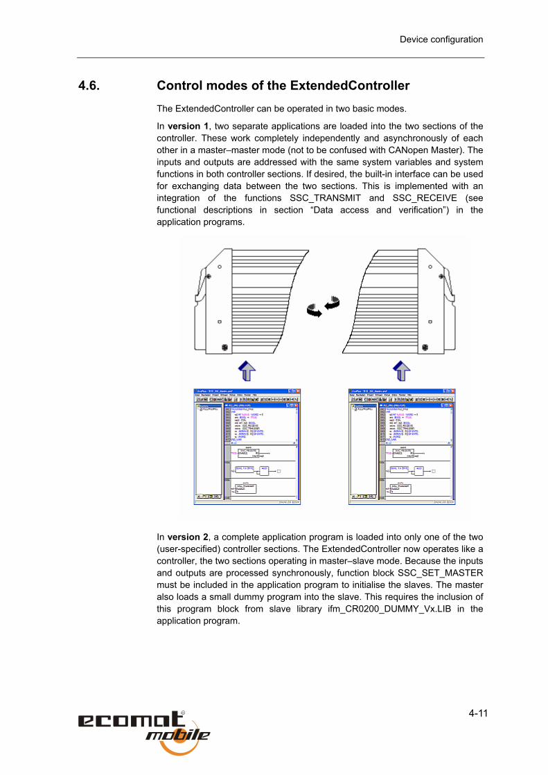
4.6. Control modes of the ExtendedController The ExtendedController can be operated in two basic modes.
In version 1, two separate applications are loaded into the two sections of the controller. These work completely independently and asynchronously of each other in a master–master mode (not to be confused with CANopen Master). The inputs and outputs are addressed with the same system variables and system functions in both controller sections. If desired, the built-in interface can be used for exchanging data between the two sections. This is implemented with an integration of the functions SSC_TRANSMIT and SSC_RECEIVE (see functional descriptions in section “Data access and verification”) in the application programs.
In version 2, a complete application program is loaded into only one of the two (user-specified) controller sections. The ExtendedController now operates like a controller, the two sections operating in master–slave mode. Because the inputs and outputs are processed synchronously, function block SSC_SET_MASTER must be included in the application program to initialise the slaves. The master also loads a small dummy program into the slave. This requires the inclusion of this program block from slave library ifm_CR0200_DUMMY_Vx.LIB in the application program.

Control modes of the ExtendedController
4-12
Synchronisation
Exchange of input/output variables and system markers
Exchange of signals from user programs
Here, too, the same system variables and system functions are addressed. To draw a distinction, an _E (for Extended) are appended to the variable and function names in the second control section. The data transfer between the two controller sections takes place automatically through the built-in interface.
Important:
For the 2nd controller section (slave) only a subset of the functions of the master controller is available.
The software CD contains a sample program, which illustrates the basic program structure. You are strongly advised to follow this scheme.

Device configuration
4-13
4.7. Configuring the programming system When you create a new project in CoDeSys, you must load the controller’s corresponding target file. It is the interface between programming system and hardware and you can select it in the dialog for the respective hardware component. The required libraries are automatically loaded when you select the target. You can remove them again if you do not need them or add other libraries.
In the next step the corresponding PLC configuration has to be selected first. Open the window under menu item Project/Options... and select the point Directories... (1.) In the directory list please click on the button with the 3 dots next to the entry line Project/Configuration files: (2) and, in the Explorer window which opens, select e.g. the directory ...\CoDeSys v2.3\Targets\ifm\CR0020cfg (3.). Finally, you need to select the directory with the requested version number of the configuration file, e.g. V030101

Configuring the programming system
4-14
Always use the corresponding software versions of the operating system (CR..._Vxxyyyzz.H86), the PLC configuration (CR..._Vxxyyzz.CFG) and the device library (CR..._Vxxyyyzz.LIB). These also have to match the selected target file
CR..._Vxx.TRG -> CR..._Vxxyyyzz.H86 where xx must have the same value! The basic file name is always the same!
Software versions can be seen from the identification at the end of the file name (e.g. CR7020_Vxxyyzz.H86). The placeholders xx, yy, zz are replaced by numbers from 0...99.
xx: 00 ... 99 version number
yy: 00 ... 99 release number
zz: 00 ... 99 patch number
Activating the PLC configuration
The point PLC configuration is reached via the tab Resources. Double click on PLC configuration to open the corresponding window.
The entry "__not_found__ " shows that the selected PLC configuration has not yet been activated. To activate the selected PLC configuration click menu item Extras/Standard configuration. The entry __not_found__ will be replaced by the name and the version of the previously selected device configuration

Device configuration
4-15
The configuration also provides the user with all important system and error flags, which must be processed and evaluated. They are accessed through their symbolic name or the IEC address.The structure of the inputs and outputs is also automatically included in the controller configuration. They can be given a name and are available as global variables throughout the project.

Terminal assignment
4-16
4.8. Terminal assignment The terminal assignments shown in the appendix correspond to the standard device configurations. With the terminal assignment, the input and output channels are assigned to the IEC addresses and the device terminals.
Labelling of the input/output channels
12 GNDA
12 Terminal number
GNDA Terminal marking
30 %IX0.7 BL
30 Terminal number
%IX0.7 IEC address for a binary input
BL Hardware type of input (here: binary lowside)
47 %QX0.3 BH/PH
47 Terminal number
%QX0.3 IEC address for a binary output
BH/PWM Hardware type of output (here: binary lowside or PWM highside)
The codes have the following meanings:
A Analog input
BH Binary input/output, highside
BL Binary input/output, lowside
CYL Cycle duration measurement input
ENC Rotary encoder signal input
FRQ Frequency input
H-Bridge Output with H link function
PWM Pulse-width-modulated signals
PWM I PWM output with current measurement
IH Pulse/counter input, highside

Device configuration
4-17
IL Pulse/counter input, lowside
R Readback channel for an output
Assignment of the input/output channels:
Depending on the device’s configuration, an input and/or output is available at one of the device’s terminals (see catalogue, installation instructions or data sheet for the device).


5-1
5. Operating states and operating system
5.1. Operating states After supply voltage is applied, the control module can be in one of five operating states:
Reset This state is run after each power-on-reset. The operating system is initialised and various checks are run. This temporary state is followed by the Run or Stopstate.
The LED briefly lights up orange.
Run This state is achieved:
• from the Reset state (autostart);
• from the Stop state through the Run signal
(precondition: Test mode);
Stop This state is achieved:
• from the Reset state if no program is loaded;
• from the Run state if the Stop signal is given through the interface. Precondition: Test mode.
Fatal Error The controller enters this state when an unacceptable error is identified. It canbe cancelled only with a Reset.
The LED is lit red.
No operating system
No operating system was loaded; the controller is in bootstrap loader. Before theapplication software is loaded, an operating system download must be performed.
The LED flashes green (fast).

Status LED
5-2
5.2. Status LED The built-in status LED indicates the following operating states (default setting).
LED colour Flashing Description LED off Constant off No operational voltageGreen 5 Hz No operating system loadedGreen 2.0 Hz Run Constant on StopRed 2.0 Hz Run with error Constant on Fatal ErrorYellow/orange Briefly on Initialisation or Reset checks
Operating states STOP and RUN can be changed by the programming system.
On the ClassicController and the ExtendedController, the status LED can also be set by the user program. For this purpose a colour constant from the data structure LED_COLOR can be assigned to the system variables LED (LED colour pulse) and LED_X (LED colour pause). In addition, a flashing frequency from data structure LED_MODES has to be assigned to system variable LED_MODE.
Permissible colours:
LED_GREEN, LED_BLUE, LED_RED, LED_WHITE, LED_MAGENTA, LED_CYAN, LED_YELLOW
LED_BLACK (LED off)
Permissible flashing modes:
LED_2HZ, LED_1HZ, LED_05HZ, LED_0HZ (frequency 0 Hz)
To do this, assign a word to data structures LED_COLOR and LED_MODES (LED flashing frequency).
Under fault conditions the operating system sets LED_COLOR to RED. The application should not, therefore, use this colour.
On the SmartController, CabinetController and PLC CS0015, the user program can change only the flashing frequency (LED_MODES) of the status LED.
The above table apply only if the user program does not change the LED colours and flashing modes.
5.3. Loading the operating system As supplied, no operating system is usually loaded in the controller (LED flashing green at 5 Hz). In this operating state, only the bootstrap loader is

Operating states and operating system
5-3
active, which provides the essential functions for loading the operating system (including support for the RS 232 and CAN interfaces).
The operating system download normally has to be performed only once. The application program can then be loaded without affecting the operating system. The advantages of this method are that it is not necessary to replace the EPROM when the operating system is updated and that custom operating systems can be implemented for specific applications.
The operating system is supplied on a separate disk together with this manual. You can obtain the current version from our website at www.ifm-electronic.com.
When programming, always observe that you are using the correct versions of the operating system (CR..._Vxxyyyzz.H86) and the device library (CR..._Vxxyyyzz.LIB). Otherwise an error message is issued when you download the application software. The basic filename is always the same.
Software versions are indicated by letters appended to the file name (for example CR7020_Vxxyyzz.H86), xx, yy and zz representing numbers from 0 to 99.
Xx: 00 – 99 Version number
Yy: 00 – 99 Release number
Zz: 00 – 99 Patch number
You must also make sure that the required internal libraries (created in IEC 1131), configuration files (*.cfg) and target files (*.trg) are loaded.
The operating system can be transferred to the controller with the stand-alone Downloader program (supplied on the software CD and also available for download on our website).The user program is normally transferred to the controller through the programming system. Alternatively, if the program was previously uploaded from the controller, you can use the Downloader.

Control modes
5-4
5.4. Control modes Independently of the operating states, the controller can be operated in different control modes. The corresponding control bits can be set and reset with the application software or, in Test mode, with the CoDeSys programming software (Global variables window).
TEST This control mode is set through the application of a High level (supply voltage) at the Test input. In the RUN and STOP states, the controller can now receive commands through one of the interfaces and, for example, communicate with the programming system. Software downloads into the controller can be performed only in this mode. With the TEST marker, the state of the user program can be scanned.
SERIAL_MODE The serial interface is available for data exchange in the application. Debugging the application software is now only possible through the CAN interface.
By default, this function is disabled (FALSE). With marker SERIAL_MODE, the state can be controlled and scanned through the user program or the programming system.
DEBUG mode If input DEBUG of function SET_DEBUDG is set TRUE, the programming system or the downloader, for example, can communicate with the controller and execute system commands (for example for service functions through the CANcom GSM modem).
Software downloads are not possible in this mode, since no supply voltage is applied to the test input.

6-1
6. Error codes and diagnostics information To maximise reliability, the operating system performs internal error checks on the controller during the start/reset phase and during program execution.
The following error markers are set under fault conditions:
Error Description of error
CAN1_BUSOFF CAN 1 not on bus
CAN1_WARNING CAN 1 warning threshold reached (>= 96)
CAN1_LASTERROR Error register, CAN controller 1 *)
CAN2_BUSOFF CAN 2 not on bus
CAN2_ WARNING CAN 2 warning threshold reached (>= 96)
CAN2_LASTERROR Error register, CAN controller 2 *)
ERROR Group error bit (general)
ERROR_MEMORY Memory error
ERROR_POWER Under/overvoltage error
ERROR_VBBR Supply voltage error, VBBR
ERROR_TEMPERATURE Overtemperature error (> 85 °C) (not CR25xx and CR03xx)
Diagnostics signals Description
ERROR_Ix (byte) I/O error at the input group
ERROR_BREAK_Qx (byte) Open-circuit error at the output group
ERROR_SHORT_Qx (byte) Short-circuit error at the output group
*) Access to CANx_LASTERROR required detailed knowledge of the CAN controller andis not normally required.
6.1. Response to system error The responsibility for responding to error markers rests entirely with the programmer.
The specific error bits and bytes should be processed by the user program. The user program must reset all error markers. The error marker yields a description of the error, which can be further processed if necessary.

Response to system error
6-2
If a serious error occurs, the ERROR bit can additionally be set. The operation LED then lights up red, the Error output (pin 13) changes to LOW and the monitoring relays (if used) are switched off so that outputs they protect drop out.
With the logic link through the relay bit or bit Relais_Clamp_15 (see chapter 3), all other outputs are also switched off.
Depending on the application, it has to now be decided whether a reset of the ERROR bit should also allow the relay – and therefore also the outputs – to be re-enabled.
For “user-defined errors”, the ERROR bit can, in addition, be set by the user program.
Because the relays are normally switched only at zero load, this function must be used to switch off the outputs only in emergencies.
To reset all outputs during normal operation, implement this function through suitable BIT links and not using the relay.
Example An ERROR_TEMPERATURE error occurs.
The operating system sets the ERROR_TEMPERATURE bit.
The user program recognises this state by querying the corresponding bits.
If necessary, the ERROR bit can be set:
This causes the operating status LED to flash red and the safety relay to dropout, causing all outputs to be switched off. The level of the Error output changesto Low.
Finally, the ERROR bit may have to be cleared by the user program. The relaypicks up again and the LED flashes green.

7-1
7. Notes about programming and system resources The user-programmable devices of the R 360 controller series contain many functions that allow the devices to be used in a wide range of applications.
The amount of system resources these functions require depends on their complexity, so that it is not always possible to run all functions at the same time or in multiple instances.
Note also the CPU used in each device: while the Classic- and ExtendedController ranges have a 40 MHz CPU, the Smart- and CabinetController have only 20 MHz, and therefore only half of the processing capacity of the faster controller types.
The following functions place an above-average load on the system resources:
CYCLE, PERIOD, PERIOD_RATIO, PHASE
Use of several measuring channels with a high input frequency
OUTPUT_CURRENT_CONTROL, OCC_TASK
Simultaneous use of several current controllers
CAN interface High baud rate (> 250 Kbit) with a high bus load
PWM, PWM100 Many simultaneous PWM channels. Especially the channels from no. 4 are noticeably more time-critical
SSC interface High data traffic on the ExtendedController’s internal interface
The above functions trigger system interrupts. This means that every call (for example through a high bus load on the CAN bus or a high input frequency at the CYCLE input) increases the user program’s cycle time.
Observe the following guideline values:
ClassicController
Current controller Up to 8 Where possible do not use any other functions that use system resources
1 channel Input frequency <= 10 kHz CYCLE, PERIOD, PERIOD_RATIO, PHASE 4 channels Input frequency <= 2 kHz

Response to system error
7-2
ExtendedController
Current controller Up to 2 x 8 Where possible do not use any other functions that use system resources
1 channel Input frequency <= 10 kHz CYCLE, PERIOD, PERIOD_RATIO, PHASE 4 channels Input frequency <= 2 kHz
SSC interface Optimize the data volume
SmartController
Current controller Up to 1 More channels may be possible if no further functions that place a high load on system resources are used
1 channel Input frequency <= 5 kHz CYCLE, PERIOD, PERIOD_RATIO, PHASE 4 channels Input frequency <= 1 kHz
When you create the user program, observe the above recommendations and test the system load. You may then have to restructure software and system structure to optimize the cycle time.
Watchdog behaviour For all controllers the program runtime is monitored by a watchdog. If the maximum watchdog time is exceeded, the controller carries out a reset and starts again. Depending on the hardware the time response of the individual devices is different.
ClassicController / ExtendedController CR0020, CR0505, CR0200
100 ms
SafetyController CR7020, CR7505, CR7200
100 ms
CabinetController CR0301, CR0302
100-200ms
SmartController CR2500, CR2501, CR2502
100-200ms

8-1
8. CAN in the ecomat controller
8.1. General information
CAN interfaces The controllers are each equipped with one or two CAN interfaces. On deviceswith two interfaces, these can be used independently of each other. Thefollowing functions are available:
Devices with one CAN interface/ CAN interface 1
CAN layer 2 CANopen master/slave (CoDeSys) Network variables (CoDeSys)
CAN interface 2 CAN layer 2 SAE J 1939/ISO 11992 (CR2501 only)
Use of identifier 0 – 2047 Identifier freely available for data transfer
System configuration
The controllers are supplied with download identifier 127. The download systemuses this identifier for the first communication with an unconfigured modulethrough CAN. You can set the download identifier through the programmingsystem’s PLC browser, the downloader or the user program.
Because the download function uses the CANopen SDO service (even whenthe controller is not operated in CANopen mode), all control modules on thenetwork must have a unique identifier. The actual COB IDs are generated fromthe module number according to the “predefined connection set”. Only oneunconfigured module can be connected to the network at any one time. Afterthe new ID (1 to 126) has been assigned, a download or debugging can takeplace and a new device connected to the system.
The download IDs are set independently of the CANopen identifiers. Make sure that they do not coincide with the download IDs or the CANopen node number of the other controllers or network stations.
Controller program download CANopen
ID COB-ID SDO Node ID COB-ID SDO 1 1
2 2
3 3
: :
126 126
127
COB-ID TX: 0x580 + download ID COB-ID RX: 0x600 + download ID
127
COB-ID TX: 0x580 + node ID COB-ID RX: 0x600 + node ID

CAN data exchange
8-2
8.2. CAN data exchange
CAN communications use layer 2 of the 7-layer ISO/OSI reference model defined in the international ISO 11898 standard.
The CAN protocol has multimaster-capability, meaning that each bus node can transmit messages. The data exchange works similar to radio communications: data is sent to the bus without sender or address, but with an identifier. Each node is responsible for receiving the data and for determining its relevance to itself using the identifier. This process is performed automatically by the CAN controller together with the operating system.
For normal CAN data exchange, the user program has to identify the data objects with their identifiers to the system using functions CANx_RECEIVE and CANx_TRANSMIT. With these functions, the RAM address of the working data, the data type and the selected identifier are merged into a single data object which then participates in the data exchange through the CAN bus. The transmitted and received objects can be defined as any valid IEC data type (for example BOOL, WORD, INT, or ARRAY).
The CAN message consists of an identifier and up to eight data bytes. Identifiers can be selected between 0 and 2047. As already mentioned, they identify the message, not the sending or receiving module. For data transfer to take place, a transmitting object must be declared in the sending module and a receiving module in at least one other module. Both of these declarations must be assigned to the same identifier.
Receiving data Received data objects are automatically (i.e. without user-interaction) placed in buffer memory.
Buffer memory is allocated to each identifier. The user software processes this queue according to the FIFO (first in, first out) principle using the CANx_RECEIVE function.
Transmitting data
When the CANx_TRANSMIT function is called, the user program sends oneCAN message to the CAN controller which signals whether it has successfullyreceived the information and sends the data on to the CAN bus.
If the controller is currently transmitting a data object and therefore not ready, itrejects the transmit request. The user program must then repeat the transmitrequest. A bit is set to indicate this situation.
8.3. CAN errors and error handling The error mechanisms described below are automatically processed by the CAN controller built into the controller. The user program can not influence this process and should merely respond to reported errors.
The CAN error mechanisms have the following aims:

CAN in the ecomat controller
8-3
• To ensure standardised data object across the entire CAN network.
• To ensure continuous network operation even when a CAN node is defective.
• Distinction between temporary and permanent CAN node defects.
• Identification and isolation of a defective node in two stages (error-passive, bus-off) to provide nodes with a temporary fault with a recovery period.
The following simplified error handling procedure is given to provide interested users with an overview of the CAN controller’s behaviour in a fault condition. After error detection, the information is automatically processes is then available in the user software in the form of CAN error bits.
Error message If a bus node detects an error condition, it immediately sends an error flag, thuscausing the transmission to be aborted or the error-free messages alreadyreceived by other nodes to be rejected. This ensures that error-free, uniformdata is available to all nodes. Because the error flag is transferred straight away,the sender can immediately resend the faulted message (in contrast to otherfield bus systems, which wait until a defined acknowledgement time haselapsed. This is one of the most important features of CAN.
A basic problems with serial data transmission is that a permanently disturbedor faulty bus node can block the whole system. Error handling in CAN would beespecially susceptible to this danger. To avoid this problem, a mechanism isneeded which detects a faulty node and isolates it from the bus if necessary.
Error count For error counting, the CAN controller contains a transmission and a receptionerror counter, which are incremented with every faulty transmit and receiveprocess respectively. With error-free transmissions, the counts are decrementedagain.
Because the increments on faulty transmissions are greater than thedecrements for successful ones, the counts can increase significantly over timeeven if the number of successful transmissions is greater than the number offaults. If no transmission errors occur over longer periods of time, the counts arereduced again. The error counts therefore provide a measure of the relativefault frequency.
If one node detects an error before the others (i.e. if it caused the fault), thisnode’s error count is incremented by a higher value than the others. If an errorcount exceeds a specified value, it is likely that the associated node isdefective. To prevent error-active signals from this node interrupting buscommunications, its status is changed to error-passive.

Physical connection to the CAN bus
8-4
Error-active state
An error-active node takes part in all bus communications and can signal detected errors by sending the active error flag. As already mentioned, this destroys the transmitted message.
Error-passive state
An error-passive node, is still capable of full communications. But it is only allowed to signal an error it detects with a passive-error flag that does not interfere with bus operation. Error-passive nodes become error-active again when the error count drops below a specified value. When the error count reaches 96, system variable CANx_WARNING is set. The node is still error-active in this state.
Bus-off state If the error count continues to increase, the bus switches the node off (i.e. to bus-off state) when a specified limit count is reached.
To indicate this state, error bit CANx_BUSOFF is set.
The operating system handles and resets CANx_BUSOFF errors automatically. For a more thorough error handling or evaluation by the user program, use function block CANx_ERRORHANDLER. In that case, the user program must also reset all CANx_BUSOFF errors.
8.4. Physical connection to the CAN bus The data transfer and error handling mechanisms described in sections 8.2. and 8.3. are implemented in the CAN controller itself. The physical connection of the CAN nodes is described in ISO 11898 under Layer 1.
The network topology
The ISO 11898 standard specifies a CAN network with a bus topology.

CAN in the ecomat controller
8-5
The bus must be terminated at both ends with a 120 Ω terminating resistor. Devices from ifm electronic that are fitted with a CAN interface do not have terminating resistors.
Because the total bus length determines the level of reflection on the bus, nodes (node 1 to Node n) should, if possible, not be connected via spur lines. If spur lines are necessary (for example to an I/O module), keep them as short as possible. Spur lines with a length of 2 m (referred to 125 kBit/s) are generally no problem, but the total length of all spur lines within the system should not be greater than 30 m. In special cases it may be necessary to precisely calculate the total line length of the bus and its spurs.
The bus level The CAN bus is in its inactive (coercible) state when the output transistor pairs
are de-energised in all bus nodes. If at least one transistor pair is switched on, abit is set on the bus, to set the bus active (dominant). Current then passesthrough the terminating resistors, generating a potential difference between thetwo bus lines. The coercible and dominant states are converted tocorresponding voltages in the bus nodes and detected by the recipient circuits.
This differential transmission with a common return line clearly improves transmission reliability. Interference voltages from external sources and frame potential transfers affect both signal lines to the same extent and therefore cancel each other out.

Physical connection to the CAN bus
8-6
The bus line length
The length of the bus line depends on the bus connection used (cable,connectors), the line resistance and the required data transfer rate. In addition,as described above, the length of the spur lines must be taken into account innetwork utilisation calculations. The graph below is a simplified representationof the relationship between bus length and baud rate.
Cable cross-sections
The cross-section of the bus cable must be taken into account in the busdesign. The table below illustrates the dependence of the cable cross-sectionon the cable length.
Cable length Cable cross-section
100 m 0.25 – 0.34 mm2
250 m 0.34 – 0.5 mm2
500 m 0.5 – 0.75 mm2
Depending on EMC requirements, a screened or unscreened parallel or twisted pair bus cable can be used.

CAN in the ecomat controller
8-7
Physical layer according to ISO 11992-1
The physical layer as specified in ISO 11992-1 has a higher voltage level thanthat defined in ISO 11898. Point-to-point network connections are used here.The termination networks are already built-in. ISO 11992-1 is built into thesecond CAN interface of the CR2501 SmartController.

General notes about the use of CAN
8-8
8.5. General notes about the use of CAN If you are using CAN or CANopen in connection with the ecomat R 360 CAN or CANopen, you need to observe several points regarding the physical network configuration and the correct use of the software.
Physical network configuration
In summary, the following applies to the CAN configuration:
• Don not select a higher data transfer rate than is necessary. A low transferrate increases system reliability.
• Do not exceed total cable length for chosen data transfer rate. For125 Kbit/s it is normally 400 m.
• Lay the cable as a bus and avoid spur lines. To avoid unnecessaryresistance, make clean, secure connections to the bus. If necessary, usetwisted-pair and/or screened cables.
• Fit 120 Ω terminating resistors at both ends of the bus line.
• The higher the number of networked nodes, the more important are theexact network dimensions (cable types and lengths, etc.).
Software for CAN and CANopen
• Using functions CANx_TRANSMIT and CANx_RECEIVE, the ecomat R 360controllers can participate directly in layer 2 CAN communications.InCANopen control mode, the specified services from the CoDeSysprogramming system are available to the programmer.
Note the following points:
• In CAN Direct mode on layer 2, all services must be implemented in theuser program. The controller is in this state after a program download or aReset command from the programming system.
• To enable CANopen control mode, include the CoDeSys CANopen systemlibraries (i.e. enable the functions in the target system settings). Dependingon the selected function, the R 360 runs as CANopen master or slave (seesection 7.7.ff).

CAN in the ecomat controller
8-9
8.6. Description of the CAN function blocks In this section, the CAN function blocks available for use in the user program are described.
To use the full capability of CAN, draw up a detailed bus concept before beginning with the program creation. In addition to the response to any CAN errors, the number of data objects with their identifiers must be specified. The data transfer frequency must also be taken into account and the CANx_TRANSMIT and CANx_RECEIVE functions be invoked at an appropriate frequency. Make sure that the transmission requests from the user program are successfully transferred to CANx_TRANSMIT (using the RESULT bit) and that the received data is read from the queue with CANx_RECEIVE and then immediately processed by the program.
To allow a communication connection to be established, all CAN nodes must be set to the same baud rate. On the ecomat R 360, this is done with function CAN1_BAUDRATE or using function block CAN2.
Regardless whether the devices have one or two CAN interfaces, the associated functions are numbered according to the associated interface (for example CAN1_TRANSMIT or CAN2_RECEIVE). In the documentation, these numbers are always replaced with an “x” for simplicity (for example CANx_TRANSMIT).
Sample program
An FBD (Function Block Diagram) sample program is included on the ecolog software and tools CD. This program exchanges data objects with a further CAN node using identifiers 1 and 2. The other node must have a Receive identifier for the Transmit identifier of the node running the program and vice versa.

Description of the CAN function blocks
8-10
Function CAN1_BAUDRATE
Library
Function symbol
Purpose Sets the data transfer rate for the bus node.
Parameters Function inputs
Name Data type Description
ENABLE BOOL TRUE: The function is processed
FALSE: The function is not processed.
BAUDRATE WORD Value of baud rate to be set in Kbit/s
(50, 100, 125, 250, 500, 1000 )
Function outputs: none
Description The CAN1_BAUDRATE function sets the data transfer rate for the control module. It does this by applying the value Kbit/s at function input BAUDRATE. Once the function is completed, this new value is saved in the device and is therefore available again after a power failure. The factory-set baud rate value is 125 Kbit/s.
This function should be run only once on initialisation during the first program cycle. Thereafter it is inhibited with input ENABLE.
The baud rate changes only after a reset (voltage off and on or soft reset).
In the slave module of the ExtendedController the baud rate is only stored after the voltage has been switched off/on.

CAN in the ecomat controller
8-11
Function CAN1_DOWNLOADID
Library
Function symbol
Purpose Sets the download identifier for the first CAN interface.
Parameters Function inputs
Name Data type Description
ENABLE BOOL TRUE: The ID is set
FALSE: Function disabled
ID BYTE Download identifier
(value range 1 to 127)
Function outputs: none
Description With function CAN1_DOWNLOAD, the communication identifier for program download and debugging can be set. The new value is entered when function input ENABLE is set TRUE. The new download ID becomes active after switching the power supply off and on again or performing a soft reset.
Make sure that every controller on the network has a unique download ID.
If you are using the controller in a CANopen network, the download ID must not be the same as a module ID (node number) of any other node.
In the slave module of the ExtendedController the download ID is only stored after the voltage has been switched off/on.

Description of the CAN function blocks
8-12
Function CANx_TRANSMIT
Library
Function symbol
Purpose Passes a CAN data object (message) to the CAN controller for transfer.
Parameters Function inputs
Name Data type Description
ID WORD Contains the number of the data object identifier. Possible values: 0 – 2047.
DLC BYTE Number of bytes to be transferred from DATA array. Permissible values: 0 – 8)
DATA ARRAY The array contains up to 8 data bytes
ENABLE BOOL TRUE: The function is processed
FALSE: The function is not processed.
Function outputs
Name Data type Description
RESULT BOOL TRUE: The function has accepted the transmission request (only one cycle set).
Description CANx_TRANSMIT is called for each data object in the program cycle, alsoseveral times in long program cycles. The user program must process theRESULT bit to ensure that its transmission request was accepted. As a rule ofthumb, one transmit request per millisecond can be executed at 125 Kbit/s.
Through bit input ENABLE, the execution of the function can be temporarilyinhibited, for example to prevent a bus overload. It also allows the simultaneoustransmission of several data objects by assigning a marker flag to each dataobject to control the function’s execution using the ENABLE input.
To use this function, function CAN2_TRANSMIT must first be executed to initialise the second CAN interface.

CAN in the ecomat controller
8-13
Function
CANx_RECEIVE
Library
Function symbol
Purpose Configures a data receive object and reads the data object’s receive buffer.
Parameters Function inputs
Name Data type Description
CONFIG BOOL This bit must be set TRUE once during configuration of the data object. For the remaining program execution it is FALSE.
CLEAR BOOL Clears the buffer (queue)
ID WORD Contains the number of the data object identifier. Possible values: 0 – 2047.
Function outputs
Name Data type Description
DATA ARRAY The array contains up to 8 data bytes
DLC BYTE Number of transferred bytes in array DATA.
Possible values: 0 – 8.
RTR BOOL Is not supported
AVAILABLE BYTE Number of received messages
OVERFLOW BOOL TRUE: Buffer overflow.
Loss of data!
FALSE: Buffer not yet full

Description of the CAN function blocks
8-14
Description CANx_RECEIVE must be called once for each data object in the initialisationphase to notify the CAN controller of the data objects’ identifiers.
In the remaining program cycle, CANx_RECEIVE is called to read out therespective receive buffer. Also several times in long program cycles. The userprogram must evaluate the AVAILABLE byte so that newly received data objectsare read from the buffer and processed. Each call of this function reduces thevalue of byte AVAILABLE by 1. If the buffer contains no data, the value ofAVAILABLE is 0.
The OVERFLOW bit indicates a buffer overflow: when the OVERFLOW bit isset, at least one data object has already been lost.
To use this function, function CAN2_RECEIVE must first be executed to initialise the second CAN interface.

CAN in the ecomat controller
8-15
Function
CAN1_ERRORHANDLER
CAN2_ERRORHANDLER
Library
Function symbol
Purpose Error routine for monitoring the CAN interface.
Parameters Function inputs
Name Data type Description
BUSOFF_RECOVER BOOL Status Bus-Off will be removed
(TRUE for one cycle)
CAN_RESTART BOOL New initialisation of CAN interface 1
(TRUE for one cycle)
Function outputs: none
Description CANx_ERRORHANDLER monitors the CAN interfaces and processes the CANerrors. If a specified number of transfer errors occurs, the CAN node changes toerror-passive mode. If the error rate falls again, the node becomes error-activeagain (normal state).
If a node is already in error-passive mode and further transfer errors occur, it isswitched off by the bus (bus-off) and the error bit CANx_BUSOFF is set. Itsreconnection to the bus is possible only when the status Bus-off is removed(BUSOFF_RECOVER).
Function input CAN_RESTART is used for rectifying other CAN errors. The CANinterface is new initialised.
The user program must then reset the transmit error bit.

Description of the CAN function blocks
8-16
The procedure for restarting an interface depends on the interface:
CAN interface 1 or devices with only one CAN interface:
Set input CAN_RESTART TRUE for one cycle.
CAN interface 2:
Set input START in function CAN2 TRUE for another cycle.
Before you can use the second CAN interface, it must always be initialized with function CAN2.
If the automatic bus recover function is to be used (default setting), function block CANx_ERRORHANDLER must not be instantiated in the program.

CAN in the ecomat controller
8-17
Function
CAN2
Library
Function symbol
CAN2
ENABLESTARTEXTENDED_MODEBAUDRATE
Purpose Initialises the second CAN interface.
Parameters Function inputs
Name Data type Description
ENABLE BOOL TRUE: The function is processed
FALSE: The function is not processed.
START BOOL TRUE: Function being initialised, first cycle
FALSE: Initialisation cycle has finished.
EXTENDED_Mode
BOOL TRUE: Second CAN interface working with 29-bit identifier
FALSE: Second CAN interface working with 11-bit identifier
BAUD RATE
WORD Baud rate: 50 kbit/s – 500 kbit/s
(50, 100,125, 250, 500)
Function outputs: none
Description This function must be called if the second CAN interface is to be used. Any baud rate changes become active only after the power supply has been switched off and on again. CAN 1 and CAN 2 can have different baud rates. Input Start is set for only one cycle when the interface is restarted. For the second CAN interface, function libraries for J1939 and ISO 11992 are also available.
Function CAN2 must be run before any other CAN2_... functions.

CANopen in the ecomat R 360
8-18
8.7. CANopen in the ecomat R 360 Layers 1 and 2 – described at the start of chapter 6 – define the physical connection and the data transfer between the bus nodes. In practice, this means that the programmer must specify the data protocol for the use of CAN in an application.
To ensure a uniform protocol layer for networking the nodes that describes the significance of the transferred data, the CAL (CAN Application Layer) was specified as layer 7. CANopen builds on CAL and specifies the CAL services used for transmitting each data type. The meaning of the data for each device type (I/O module, drives, shaft encoders, etc.) is also defined. These rules provide the application programmer with access to all CANopen-capable components with little effort. CANopen nodes belonging to the same device family have their data organised in the same way. The properties of these device classes are summarised in the “Device Profiles” (DS-40x).
Despite these rules, the basic structure of CAN that allows each bus nodes to place data onto the network remains intact. Only the network (NMT) master is unique and serves mainly to start up and monitor the system.
The mechanisms described below aim to provide a brief overview of the functions of CANopen. To make the best use of the CANopen protocol and its capability in a specific application, we recommend further reading (information about CAN in Automation e.V. (CiA), Erlangen, Germany).
General information about CANopen
Every CANopen node has an object directory that can be addressed withService Data Objects (SDOs). In addition, at least two process data objects(PDOs) for transmitting and receiving process data, a node-guarding orheartbeat object for implementing network monitoring, and an EmergencyObject for signalling error conditions are available.
The object-oriented identifiers (11-bit) are termed CAN Object IDs (COB-IDs)under CANopen. They are split into 16 groups through the four mist significantbits (MSBs). The remaining seven bits are used to distinguish between 127CANopen nodes to provide a unique assignment of the individual object typesto the nodes. This default assignment
is specified in the predefined connection set. It can be changed to suit specificapplications, but to allow a flexible selection of different manufacturers’CANopen devices, it is advisable to carefully consider whether to take this step.

CAN in the ecomat controller
8-19
Object COB IDs
(hex)
COB IDs
(decimal)
Default function
NMT 0 0 Network management
SYNC 80 128 Synchronisation
EMCY 80 + node ID (81 – FF)
128 + node ID (129 – 255)
Error conditions
TIME STAMP 100 256 Network time
PDO1(tx) 180 + node ID (181 – 1FF)
384 + node ID (385 – 511)
PDO transmit
PDO1(rx) 200 + node ID (201 – 27F)
512 + node ID (513 – 639)
PDO receive
PDO2(tx) 200 + node ID (281 – 2FF)
6402 + node ID (641 – 767)
PDO transmit
PDO2(rx) 300 + node ID (301 – 37F)
768 + node ID (769 – 895)
PDO receive
PDO3(tx) 380 + node ID (381 – 3FF)
896 + node ID (897 – 1023)
PDO transmit
PDO3(rx) 400 + node ID (401 – 47F)
1024 + node ID (1025 – 1151)
PDO receive
PDO4(tx) 480 + node ID (481 – 4FF)
1152 + node ID (1153 – 1279)
PDO transmit
PDO4(rx) 500 + node ID (501 – 57F)
1280 + node ID (1281 – 1407)
PDO receive
SDO(tx) 580 + node ID (581 – 5FF)
1408 + node ID (1409 – 1535)
Master–>slave SDO
SDO(rx) 600 + node ID (601 – 67F)
1536 + node ID (1537 – 1663)
Slave->master SDO
Node guarding/heartbeat
700 + node ID (701 - 77F)
1792 + node ID (1793 – 1919)
Node/life guarding or heartbeat
The object directory
All node parameters are stored in the object directory of the correspondingCANopen node. For unique identification, each directory entry is marked with anindex (IDX, length 16 bits) and a subindex (SUBIDX, length 8 bits). These areplaced in the individual index ranges by parameter type. The meanings of theindices for the communication and default parameters are defined in theCANopen standard for each device type. In addition, a range for manufacturer-specific data is available. Here, for example, the configuration parameters forifm electronic’s I/O modules are saved.

CANopen in the ecomat R 360
8-20
Index (hex) Object
0000 Not used
0001 – 009F Data types
00A0 – 0FFF Reserved
1000 – 1FFF Range for the communication profile
2000 – 5FFF Range for manufacturer-specific data
6000 – 9FFF Range for default device parameters
A000 – FFFF Range for general IEC 61131–3 network variables
Service data objects (SDO)
Read and write access to the object directory is achieved with the service dataobjects (SDOs).
The SDOs are used for all data in CANopen that is not time-critical. They areonly ever transmitted from point to point (network master/slave). The SDOs arechiefly used to transmit the CAN node configuration data during the boot-upphase.
Process data objects (PDO)
Time-critical process data is transferred using the process data objects (PDOs).These can be freely exchanged between the individual nodes (PDO linking).The transfer method (synchronous or asynchronous) is also defined. Dependingon the type of data to be transferred, the right choice of transmission type canconsiderably reduce CAN bus load. The default settings of the ifm electronic I/Omodules specify synchronous transfer of analog input data and all output dataand event-controlled (asynchronous) transfer of digital input data.
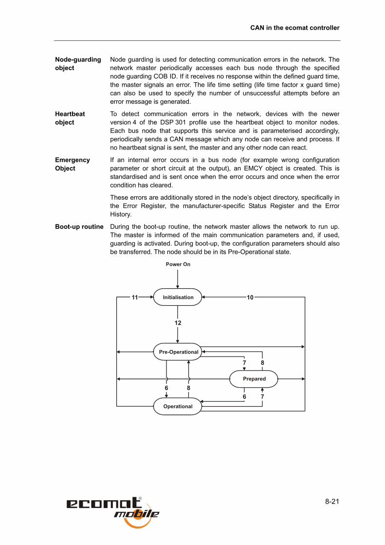
CAN in the ecomat controller
8-21
Node-guarding object
Node guarding is used for detecting communication errors in the network. Thenetwork master periodically accesses each bus node through the specifiednode guarding COB ID. If it receives no response within the defined guard time,the master signals an error. The life time setting (life time factor x guard time)can also be used to specify the number of unsuccessful attempts before anerror message is generated.
Heartbeat object
To detect communication errors in the network, devices with the newerversion 4 of the DSP 301 profile use the heartbeat object to monitor nodes.Each bus node that supports this service and is parameterised accordingly,periodically sends a CAN message which any node can receive and process. Ifno heartbeat signal is sent, the master and any other node can react.
Emergency Object
If an internal error occurs in a bus node (for example wrong configurationparameter or short circuit at the output), an EMCY object is created. This isstandardised and is sent once when the error occurs and once when the errorcondition has cleared.
These errors are additionally stored in the node’s object directory, specifically inthe Error Register, the manufacturer-specific Status Register and the ErrorHistory.
Boot-up routine During the boot-up routine, the network master allows the network to run up.The master is informed of the main communication parameters and, if used,guarding is activated. During boot-up, the configuration parameters should alsobe transferred. The node should be in its Pre-Operational state.

CANopen in the ecomat R 360
8-22
Status Description
6 Start Remote Node indication
7 Stop Remote Node indication
8 Enter Pre-Operational State indication
10 Reset Node indication
11 Reset_Communication indication
12 Initialisation finished – enter Pre-Operational automatically
To ensure a successful boot-up, at least the node number and baud rate of the CAN node must be set. This setting must match the master’s baud rate You can set the baud rate with DIP switches on the node or by software through the object directory. Because the ecomat R 360 controller also allows the SDOs to write to the object directory, these settings can also be made using the controller.
To enable CANopen control mode, include the CoDeSys CANopen system libraries or enable the functions in the target system settings. Depending on the selected function, the R 360 controllers run as CANopen master or slave.

CAN in the ecomat controller
8-23
8.8. CANopen support in CoDeSys If the ecomat mobile controllers are to communicate using the CANopen protocol, the required settings are made directly from the programming system using the controller configuration. The controller can be operated in two basic modes: as CANopen master or as CANopen slave (device). For a detailed description of the settings and how to use the controller and CANopen configuration dialog, see Resources/Controller configuration in the CoDeSys manual or the online help.
CANopen master
To use the controllers as CANopen master, first attach the CANopen master inthe PLC Configuration window with Insert/Append Subelement. On controllerswith two interfaces, interface 1 is automatically configured as master. Allrequired libraries are automatically inserted in the Library Manager.
In the dialog, you can set the baud rate, node number (not the download ID!)and the sync. parameters for the master.
If the other nodes in the network support heartbeat, you can select optionSupport DSP301, V4.01....

CANopen support in CoDeSys
8-24
Next, add the CAN slaves. To do this, select Insert/Append Subelement in thePLC Configuration dialog again. From the list of CANopen device descriptions(ESD files) saved in folder PLC_CONF, you can select the appropriate device,which is then inserted into the tree view in the PLC configuration window.
The node number is automatically incremented. Depending on the device nodeguarding, a life time factor or heartbeat must be set. With Service Data Objects,you can also change the manufacturer-specific device parameters (for examplethe I/O configuration).
Using Receive PDO mapping or Transmit PDO mapping in the Propertiesdialog, you can also set the transmission type and its parameters for each PDO.
The settings you make in this dialog have no effect on the CAN slave’s objectdirectory. They are normally written at each start of the user program,regardless of whether they are permanently saved in the CAN device.
CANopen support through CoDeSys can be enabled only for CAN interface 1. If the CAN master has already been defined, the PLC can no longer be used as CAN device through CoDeSys. You can, however, implement a separate protocol on interface 2 or use the SAE J1939/ISO11992 protocol any time.
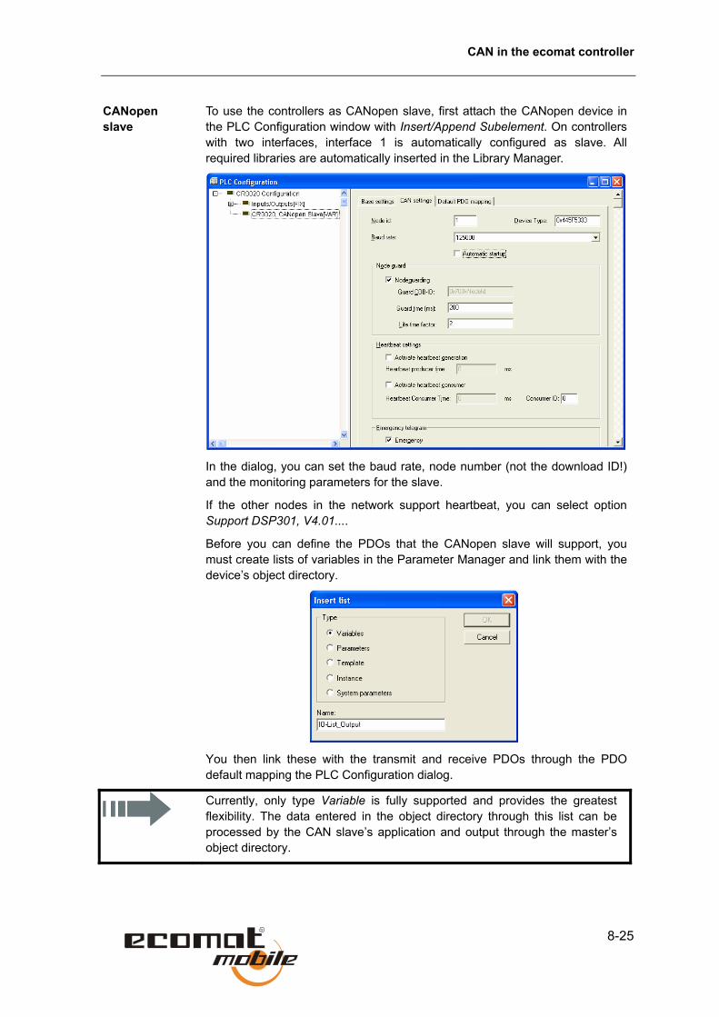
CAN in the ecomat controller
8-25
CANopen slave
To use the controllers as CANopen slave, first attach the CANopen device in the PLC Configuration window with Insert/Append Subelement. On controllers with two interfaces, interface 1 is automatically configured as slave. All required libraries are automatically inserted in the Library Manager.
In the dialog, you can set the baud rate, node number (not the download ID!) and the monitoring parameters for the slave.
If the other nodes in the network support heartbeat, you can select option Support DSP301, V4.01....
Before you can define the PDOs that the CANopen slave will support, you must create lists of variables in the Parameter Manager and link them with the device’s object directory.
You then link these with the transmit and receive PDOs through the PDO default mapping the PLC Configuration dialog.
Currently, only type Variable is fully supported and provides the greatest flexibility. The data entered in the object directory through this list can be processed by the CAN slave’s application and output through the master’s object directory.

CANopen support in CoDeSys
8-26
Note the following:
Data to be read by the CAN master (such as inputs or system variables) must have read-only access.
Data to be written to by the CAN master (such as slave outputs) must have write-only access.
SDO parameters that the CAN master will write to and that will be read and written to by the slave application must have read-write access.
In PLC Configuration dialog, you then link the variable lists from the Parameter Manager to the transmit and receive PDOs.
If more than eight data bytes are mapped in a PDO, the next free identifiers are automatically used until all data bytes can be transmitted. To obtain a clear structure of the used identifiers, you should insert the correct number of receive and transmit PDOs and assign the variable bytes from the lists to them.

CAN in the ecomat controller
8-27
Function
CAN1_SDO_READ
Library
Function symbol
Purpose Reads the SDO with the specified indices from the node.
Parameters Function inputs
Name Data type Description
ENABLE BOOL TRUE: The function is processed
FALSE: The function is not processed
NODE BYTE Node number
IDX WORD Index in object directory
SUBIDX BYTE Subindex relating to index in object directory
DATA DWORD Address of the receive data array (length 0 to 255). Transfer through ADR operator
Function outputs
Name Data type Description
RESULT BYTE 0 Function not active
1 Function completed
2 Function is active
3 Function was not executed

CANopen support in CoDeSys
8-28
Description Function CANx_SDO_READ is used for reading the entries in the objectdirectory. This provides targeted access to specific node parameters. To use thisfunction, the node must be in Pre-Operational or Operational state.
CANx_SDO_READ may only be used if the controller is operated in theCANopen master mode.

CAN in the ecomat controller
8-29
Function
CAN1_SDO_WRITE
Library
Function symbol
Purpose Writes the SDO with the specified indices to the node.
Parameters Function inputs
Name Data type Description
ENABLE BOOL TRUE: The function is processed
FALSE: The function is not processed
NODE BYTE Node number
IDX WORD Index in object directory
SUBIDX BYTE Subindex relating to index in object directory
LEN WORD Length of entry in number of bytes
DATA DWORD Address of the transmit data array (length 0 to 255). Transfer through ADR operator
Function outputs
Name Data type Description
RESULT BYTE 0 Function not active
1 Function completed
2 Function is active
3 Function was not executed
Description Function CANx_SDO_WRITE is used for writing the entries in the objectdirectory. This allows targeted setting of specific node parameters. To use thisfunction, the node must be in Pre-Operational or Operational state.

CANopen support in CoDeSys
8-30
The value of LEN must correspond with the length of the Send array. Otherwise errors will arise during SDO communication.
CANx_SDO_WRITE may only be used if the controller is operated in the CANopen master mode.

CAN in the ecomat controller
8-31
8.9. Functions for using the second CAN interface to SAE J 1939 and ISO 11992 The second CAN interface in the R 360 controllers can also be used for communicating with special bus protocol for drive control and automotive applications. These protocols operate with the second interface’s CAN controller set to Extended Mode. This means that the CAN messages are transmitted with a 29-bit identifier consisting of two parts: the 11-bit ID and an 18-bit ID. Because of the identifier’s length, a large number of messages can be directly assigned to the identifier.
The protocol takes advantage of this fact by grouping messages into ID groups. The assignment of IDs is defined in standards SAE J 1939 and ISO 11992.
Since ISO 11992 is based on SAE J 1939, the two standards use the same software protocol. The physical interfaces do differ, however, the ISO 11992 type having a higher voltage level. For communicating with devices with ISO 11992 interface, control modules with a modified CAN interface are therefore required (for example SmartController CR2501).
To use the SAE J 1939/ISO 11992 functions, you will need the device manufacturer’s protocol specifications. Some manufacturers do not implement all messages or their implementation is not needed for a particular device type, end you will need to determine the messages that can be used with each type.
Structure of the identifier
Prio
rity
Res
erve
d D
ata
page
PDU format PDU specific Source/destination
address
29 28 27 26 25 24 23 22 21 20 19 18 17 16 15 14 13 12 11 10 9 8 7 6 5 4 3 2 1
To develop SAE J 1939 and ISO 11992 programs, you should have access to the following information and tools:
• List of data to be used by the devices
• List overview of the device manufacturer with all relevant data
• CAN monitor with 29-bit support
• If required, a copy of the SAE J 1939 or ISO 11992 standard

Functions for using the second CAN interface to SAE J 1939 and ISO 11992
8-32
Example of detailed message documentation
ETC1: Electronic Transmission Controller #1 (3.3.5) 0CF00203
Transmission repetition rate: 10 ms
Data length: 8 bytes
PDU format: 240
PDU specific: 2
Default priority: 3
Data page: 0
Source address: 3
Parameter group number: 0x00F002
Identifier: 0x0CF00203
Data field: We will not deal with the meaning of data bytes 1 to 8 in detail here. Please refer to the manufacturer’s documentation.
Because all relevant data is already included in the manufacturer’s example, it can be transmitted directly to the function blocks.
Legend:
Name in manufacturer’s documentation
Function input, library function
Example value
Transmission repetition rate RPT T#10ms
Data length LEN 8
PDU format PF 240
PDU specific PS 2
Default priority PRIO 3
Data page PG 0
Source address/destination address SA / DA 3
Data field SRC/DST Array address
Depending on the required function, the corresponding values are then entered. In fields SA/DA and SRC/DST the meaning (but not the value) changes depending on whether it is a receive or a transmit function.
The individual data bytes must then be read out from the array and processed according to their meaning.
Example of short message documentation

CAN in the ecomat controller
8-33
Even if the device manufacturer provides only brief documentation, the function parameters can be derived from the identifier. In addition to the ID, the transmission repetition rate and the meaning of the data arrays are needed.
For protocol messages that are not manufacturer-specific, the SAE J 1939 or ISO 11992 standard can also be used for information.
Identifier 0x0CF00203 has the following structure:
PRIO, reserv., PG PF + PS SA / DA
0 C F 0 0 2 0 3
Because the number as are hex values of which individual bits need to sometimes be read, the numbers need to be further split up.
SA / DA Source/destination address, hexadecimal
Source/destination address, decimal
0 3 0x03 3
PF PDU format (PF) hexadecimal
PDU format (PF) decimal
F 0 0xF0 240
PS PDU specific (PS)
hexadecimal PDU specific (PS)
decimal
0 2 0x02 2
PRIO, reserv., PG PRIO, reserv., PG binary
0 C 0000 1100
Of the eight bits, only the five least significant are needed.
Not required Priority Res. DP x x x 0 1 1 0 0
(decimal) 3 0 0 Further typical combinations
(binary) 1 1 0 0 0 (decimal) 6 0 0 0x18 (hex) (binary) 1 1 1 0 0
(decimal) 7 0 0 0x1C (hex)

Functions for using the second CAN interface to SAE J 1939 and ISO 11992
8-34
Function
J1939
Library
J1939_x.LIB
Function symbol
Purpose Protocol handler for SAE J 1939 communication profile.
Parameters Function inputs
Name Data type Description
ENABLE BOOL TRUE: The function is processed.
FALSE: The function is not processed.
START BOOL TRUE: Protocol handler will be started
FALSE: in cyclic program execution
MY_ADRESS BYTE Controller device address
Function outputs: none
Description To implement communications, the protocol handler must be called in every program cycle with input ENABLE set TRUE.
The protocol handler is started when the START input is set TRUE for a cycle.
MY_ADRESS transmits a device address (which must be unique) to the control module. It must differ from the addresses of the other J 1939 bus nodes and can then be read by other bus nodes.
To allow the use of J 1939 communications, the second CAN interface must first be initialised with function CAN2.

CAN in the ecomat controller
8-35
Function
J1939_RECEIVE
Library
J1939_x.LIB
Function symbol
Purpose Receiving an individual message or a message block.
Parameters Function inputs
Name Data type Description
ENABLE BOOL TRUE: The function is processed.
FALSE: The function is not processed.
CONFIG BOOL This bit must be set TRUE once during configuration of the data object. For the remaining program execution it is FALSE.
PG BYTE Page address. Normally = 0
PF BYTE PDU format byte
PS BYTE PDU specific byte
DST DWORD Destination address of the array under which the received data is saved.
RPT TIME Monitoring time within which the messages must be received again. If it is not, an error is signalled. To disable monitoring, set RPT to T#0s.
LIFE BYTE Number of permissible incorrect monitoring calls

Functions for using the second CAN interface to SAE J 1939 and ISO 11992
8-36
Function outputs
Name Data type Description
RESULT BYTE 0: Not active 1: Data has been received 3: Error signalling
Nothing received within time window (LIFE x RPT)
DEVICE BOOL Sender’s device address
LEN BYTE Number of received bytes
Description Function block J1939_RECEIVE takes care of receiving messages and message blocks. It must be initialised for each cycle with input CONFIG. During initialisation, parameters PG, PF, PS, RPT, LIFE, and the memory address of the destination address are transmitted. The address must be determined with function ADR.
The received data must be evaluated with the RESULT byte. If its value is 1, the data is available at the memory address transmitted through DST. When a new message is received, the existing data at the destination address is overwritten.
The number of received message bytes is available at function output LEN.
If RESULT = 3, no valid messages were received in the specified time (LIFE x RPT).
This function block must also be used if the messages are requested with functions J1939_........_REQUEST.
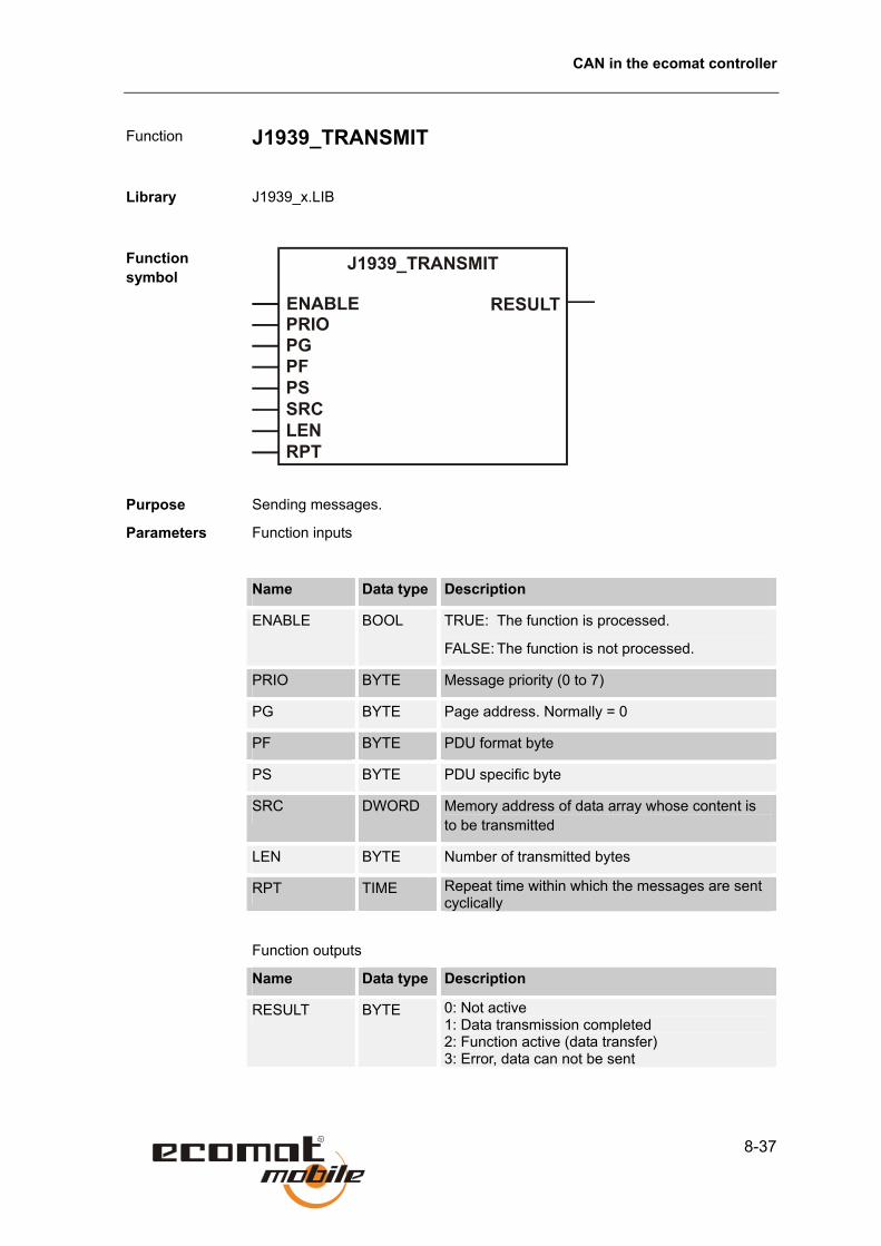
CAN in the ecomat controller
8-37
Function
J1939_TRANSMIT
Library
J1939_x.LIB
Function symbol
Purpose Sending messages.
Parameters Function inputs
Name Data type Description
ENABLE BOOL TRUE: The function is processed.
FALSE: The function is not processed.
PRIO BYTE Message priority (0 to 7)
PG BYTE Page address. Normally = 0
PF BYTE PDU format byte
PS BYTE PDU specific byte
SRC DWORD Memory address of data array whose content is to be transmitted
LEN BYTE Number of transmitted bytes
RPT TIME Repeat time within which the messages are sent cyclically
Function outputs
Name Data type Description
RESULT BYTE 0: Not active 1: Data transmission completed 2: Function active (data transfer) 3: Error, data can not be sent

Functions for using the second CAN interface to SAE J 1939 and ISO 11992
8-38
Description Function block J1939_TRANSMIT takes care of sending messages andmessage blocks. Parameters PG, PF, PS, RPT, and the address of data arraySRC are passed to the function. The address must be determined with functionADR. In addition, the number of data bytes to be transferred and the priority(normally 3, 6 or 7) must be passed to the function.
Because sending takes place over several controller cycles, it must beevaluated through the RESULT byte. If RESULT = 1, all data has beentransmitted.
If more than eight bytes are to be sent, a packet transfer is performed.

CAN in the ecomat controller
8-39
Function
J1939_RESPONSE
Library
J1939_x.LIB
Function symbol
Purpose Automatic response to a request message.
Parameters Function inputs
Name Data type Description
ENABLE BOOL TRUE: The function is processed.
FALSE: The function is not processed.
CONFIG BOOL This bit must be set TRUE once during configuration of the data object. For the remaining program execution it is FALSE.
PG BYTE Page address. Normally = 0
PF BYTE PDU format byte
PS BYTE PDU specific byte
SRC DWORD Memory address of data array whose content is to be transmitted
LEN BYTE Number of transmitted bytes
Function outputs: none
Description Function block J1939_RESPONSE is responsible for automatic sending ofmessages in response to global requests and specific requests. It must beinitialised for each cycle with input CONFIG.
Parameters PG, PF, PS, RPT, and the address of data array SRC are passed tothe function. The address must be determined with function ADR. In addition,the number of data bytes to be transferred is passed to the function.

Functions for using the second CAN interface to SAE J 1939 and ISO 11992
8-40
Function
J1939_SPECIFIC_REQUEST
Library
J1939_x.LIB
Function symbol
Purpose Requesting and receiving data from a specific network node
Parameters Function inputs
Name Data type Description
ENABLE BOOL TRUE: The function is processed.
FALSE: The function is not processed.
PRIO BYTE Priority (0.. 7)
DA BYTE Logical (destination) address of requested device
PG BYTE Page address. Normally = 0
PF BYTE PDU format byte
PS BYTE PDU specific byte
DST DWORD Destination address of the array under which the received data is saved.
Function outputs
Name Data type Description
RESULT BYTE 0: Not active 1: Data transmission completed 2: Function active (data transfer) 3: Error, data can not be sent
LEN BYTE Number of received data bytes

CAN in the ecomat controller
8-41
Description Function block J1939_SPECIFIC_REQUEST is used for automaticallyrequesting individual messages from a specific J 1939 network node. The logicDA device addresses parameters PG, PF, and PS, and the address of arrayDST in which the received data is placed are passed to the function. Theaddress must be determined with function ADR. In addition, the priority(normally 3, 6 or 7) must be passed to the function.
Because requesting takes place over several controller cycles, it must beevaluated through the RESULT byte. If RESULT = 1, all data has been received.
Output LEN indicates the number of received data bytes.

Functions for using the second CAN interface to SAE J 1939 and ISO 11992
8-42
Function
J1939_GLOBAL_REQUEST
Library
J1939_x.LIB
Function symbol
Purpose Globally requesting and receiving data from the network nodes
Parameters Function inputs
Name Data type Description
ENABLE BOOL TRUE: The function is processed.
FALSE: The function is not processed.
PRIO BYTE Priority (0.. 7)
PG BYTE Page address. Normally = 0
PF BYTE PDU format byte
PS BYTE PDU specific byte
DST DWORD Destination address of the array under which the received data is saved.
Function outputs
Name Data type Description
RESULT BYTE 0: Not active 1: Data transmission completed 2: Function active (data transfer) 3: Error, data can not be sent
SA BYTE Logical (transmit) device address of requested device
LEN BYTE Number of received data bytes

CAN in the ecomat controller
8-43
Description Function block J1939_GLOBAL_REQUEST is used for automatically requesting individual messages from all active J 1939 network nodes. The logic DA device addresses parameters PG, PF, and PS, and the address of array DST in which the received data is placed are passed to the function. The address must be determined with function ADR. In addition, the priority (normally 3, 6 or 7) must be passed to the function.
Because requesting takes place over several controller cycles, it must be evaluated through the RESULT byte. If RESULT = 1, all data has been received.
Output LEN indicates the number of received data bytes.

Functions for using the second CAN interface to SAE J 1939 and ISO 11992
8-44
Function
ISO11992
Library
ISO11992_x.LIB
Function symbol
Purpose Protocol handler for ISO 11992 communication profile.
Parameters Function inputs
Name Data type Description
ENABLE BOOL TRUE: The function is processed.
FALSE: The function is not processed.
START BOOL TRUE: Protocol handler will be started
FALSE: in cyclic program execution
MY_ADRESS BYTE Controller device address
Function outputs: none
Description To implement communications, the protocol handler must be called in every program cycle with input ENABLE set TRUE.
The protocol handler is started when the START input is set TRUE for a cycle.
MY_ADRESS transmits a device address (which must be unique) to the controlmodule, It must differ from the addresses of the other J 1939 bus nodes andcan then be read by other bus nodes.
To allow the use of ISO 11992 communications, the second CAN interface must first be initialised with function CAN2.

CAN in the ecomat controller
8-45
Function
ISO11992_RECEIVE
Library
ISO11992_x.LIB
Function symbol
Purpose Receiving an individual message or a message block.
Parameters Function inputs
Name Data type Description
ENABLE BOOL TRUE: The function is processed.
FALSE: The function is not processed.
CONFIG BOOL This bit must be set TRUE once during configuration of the data object. For the remaining program execution it is FALSE.
PG BYTE Page address. Normally = 0
PF BYTE PDU format byte
PS BYTE PDU specific byte
DST DWORD Destination address of the array under which the received data is saved.
RPT TIME Monitoring time within which the messages must be received again. If it is not, an error is signalled. To disable monitoring, set RPT to T#0s.
LIFE BYTE Number of permissible incorrect monitoring calls

Functions for using the second CAN interface to SAE J 1939 and ISO 11992
8-46
Function outputs
Name Data type Description
RESULT BYTE 0: Not active 1: Data has been received 3: Error signalling
Nothing received within time window (LIFE x RPT)
DEVICE BOOL Sender’s device address
LEN BYTE Number of received bytes
Description Function block ISO11992_RECEIVE takes care of receiving individualmessages and message blocks. It must be initialised for each cycle with inputCONFIG. During initialisation, parameters PG, PF, PS, RPT, LIFE, and thememory address of the destination address are transmitted. The address mustbe determined with function ADR.
The received data must be evaluated with the RESULT byte.If its value is 1, the data is available at the memory address transmitted throughDST. When a new message is received, the existing data at the destinationaddress is overwritten.
The number of received message bytes is available at function output LEN.
If RESULT = 3, no valid messages were received in the specified time (LIFE xRPT).
This function block must also be used if the messages are requested with functions ISO11992_........_REQUEST.

CAN in the ecomat controller
8-47
Function
ISO11992_TRANSMIT
Library
ISO11992_x.LIB
Function symbol
Purpose Sending messages.
Parameters Function inputs
Name Data type Description
ENABLE BOOL TRUE: The function is processed.
FALSE: The function is not processed.
PRIO BYTE Priority (0.. 7)
PG BYTE Page address. Normally = 0
PF BYTE PDU format byte
PS BYTE PDU specific byte
SRC DWORD Memory address of the data to be sent
LEN BYTE Number of transmitted bytes
RPT TIME Repeat time within which the messages are sent cyclically
Function outputs
Name Data type Description
RESULT BYTE 0: Not active 1: Data transmission completed 2: Function active (data transfer) 3: Error, data can not be sent
Functions for using the second CAN interface to SAE J 1939 and ISO 11992
8-48
Description Function block ISO11992_TRANSMIT takes care of sending messages andmessage blocks. Parameters PG, PF, PS, RPT, and the address of data arraySRC are passed to the function. The address must be determined with functionADR. In addition, the number of data bytes to be transferred and the priority(normally 3, 6 or 7) must be passed to the function.
Because sending takes place over several controller cycles, it must beevaluated through the RESULT byte. If RESULT = 1, all data has beentransmitted.
If more than eight bytes are to be sent, a packet transfer is performed.

CAN in the ecomat controller
8-49
Function
ISO11992_RESPONSE
Library
ISO11992_x.LIB
Function symbol
Purpose Automatic response to a request message.
Parameters Function inputs
Name Data type Description
ENABLE BOOL TRUE: The function is processed.
FALSE: The function is not processed.
CONFIG BOOL This bit must be set TRUE once during configuration of the data object. For the remaining program execution it is FALSE.
PG BYTE Page address. Normally = 0
PF BYTE PDU format byte
PS BYTE PDU specific byte
SRC DWORD Memory address of data array whose content is to be transmitted
LEN BYTE Number of transmitted bytes
Function outputs: none

Functions for using the second CAN interface to SAE J 1939 and ISO 11992
8-50
Description Function block ISO11992_RESPONSE is responsible for automatic sending ofmessages in response to global requests and specific requests. It must beinitialised for each cycle with input CONFIG.
Parameters PG, PF, PS, RPT, and the address of data array SRC are passed tothe function. The address must be determined with function ADR. In addition,the number of data bytes to be transferred is passed to the function.

CAN in the ecomat controller
8-51
Function
ISO11992_SPECIFIC_REQUEST
Library
ISO11992_x.LIB
Function symbol
Purpose Requesting and receiving data from a specific network node
Parameters Function inputs
Name Data type Description
ENABLE BOOL TRUE: The function is processed.
FALSE: The function is not processed.
PRIO BYTE Priority (0.. 7)
DA BYTE Logical (destination) address of requested device
PG BYTE Page address. Normally = 0
PF BYTE PDU format byte
PS BYTE PDU specific byte
DST DWORD Destination address of the array under which the received data is saved.
Function outputs
Name Data type Description
RESULT BYTE 0: Not active 1: Data transmission completed 2: Function active (data transfer) 3: Error, data can not be sent
LEN BYTE Number of received data bytes

Functions for using the second CAN interface to SAE J 1939 and ISO 11992
8-52
Description Function block ISO11992_SPECIFIC_REQUEST is used for automaticallyrequesting individual messages from a specific ISO 11992 network node. Thelogic DA device addresses parameters PG, PF, and PS, and the address ofarray DST in which the received data is placed are passed to the function. Theaddress must be determined with function ADR. In addition, the priority(normally 3, 6 or 7) must be passed to the function.
Because requesting takes place over several controller cycles, it must beevaluated through the RESULT byte. If RESULT = 1, all data has been received.
Output LEN indicates the number of received data bytes.

CAN in the ecomat controller
8-53
Function
ISO11992_GLOBAL_REQUEST
Library
ISO11992_x.LIB
Function symbol
Purpose Globally requesting and receiving data from the network nodes
Parameters Function inputs
Name Data type Description
ENABLE BOOL TRUE: The function is processed.
FALSE: The function is not processed.
PRIO BYTE Priority (0.. 7)
PG BYTE Page address. Normally = 0
PF BYTE PDU format byte
PS BYTE PDU specific byte
DST DWORD Destination address of the array under which the received data is saved.
Function outputs
Name Data type Description
RESULT BYTE 0: Not active 1: Data transmission completed 2: Function active (data transfer) 3: Error, data can not be sent
SA BYTE Logical (transmit) device address of requested device
LEN BYTE Number of received data bytes

Functions for using the second CAN interface to SAE J 1939 and ISO 11992
8-54
Description Function block ISO11992_GLOBAL_REQUEST is used for automaticallyrequesting individual messages from all active ISO 11992 network nodes. Thelogic DA device addresses parameters PG, PF, and PS, and the address ofarray DST in which the received data is placed are passed to the function. Theaddress must be determined with function ADR. In addition, the priority(normally 3, 6 or 7) must be passed to the function.
Because requesting takes place over several controller cycles, it must beevaluated through the RESULT byte. If RESULT = 1, all data has been received.
Output LEN indicates the number of received data bytes.

9-1
9. PWM in the ecomat controller
9.1. PWM signal processing and current control PWM (pulse-width-modulation) In control applications, it is used mainly for mobile use and adverse conditions requiring rugged equipment for controlling proportional (PWM) valves. With available accessories, pulse-width-modulated output signals can be converted into analog output voltages.
PWM output signals are clocked signals between GND and supply voltage, whose pulse/pause ratio is varied within a fixed period (the PWM frequency). Depending on the pulse/pause ratio, the required current is generated through the connected load.
The ecomat mobile controller’s PWM function is a hardware function provided by the processor. To use the controllers’ 4/8/12 built-in PWM outputs, they must be initialised in the user program and configured for the required output signal.

PWM signal processing and current control
9-2
PWM/PWM 100 Depending on the application and the required resolution, you can choose between the functions PWM and PWM100. The controller functions require a high accuracy and therefore also a high resolution. The PWM function is usually best in this case.
For a fast, easy implementation in applications with less stringent accuracy requirements, function PWM100 can be used. With this function, the PWM frequency can be input in Hz and the pulse/pause ratio in 1 % steps.
PWM frequency
The required PWM frequency depends on the controlled valve type. With the PWM function, the frequency is transmitted with the Reload value (function PWM) or directly as numerical value in Hz (function PWM100). The PWM outputs’ mode of operation depends on the controller used, but their purpose is always the same.
The PWM frequency is given by an internal count derived from the CPU clock pulse. This count is started when the PWM function is initialised and – depending on the PWM output group (0 – 3, 4 – 7 or 4 – 11) – counts down from FFFF hex or up from 0000 hex. When it reaches a reference value (VALUE), the output is set. When the count overflows (i.e. changes from 0000 hex to FFFF hex or from FFFF hex to 0000 hex), the output is reset and the process begins from the start.
With the specification of another RELOAD value, the internal count can be set to run between values other than 0000 hex and FFFF hex. This increases the PWM frequency and the reference value must then lie within the specified range.
PWM channels
0 – 3
These four PWM channels provide maximum flexibility in parameterization. A separate PWM frequency (RELOAD value) can be set and one of the functionsPWM or PWM100 selected for each channel.
Calculating the RELOAD value
The reload value of the internal PWM count depends on input DIV64 and the CPU frequency and is calculate as follows:

PWM in the ecomat controller
9-3
Classic/ExtendedController
DIV64 = 0: fPWM = 20.00 MHz / Reload
DIV64 = 1: fPWM = 312.5 kHz / Reload
Smart/CabinetController
DIV64 = 0: fPWM = 10.00 MHz / Reload
DIV64 = 1: fPWM = 156.25 kHz / Reload
Depending on whether a high or low PWM frequency is required, input DIV64 must be set to 0 or 1. For PWM frequencies below 305/152 Hz, DIV64 must be set to 1 to prevent the Reload value being larger than FFFF hex.
Example for ClassicController
Example for SmartController
The desired PWM frequency is 400 Hz.
20 MHz _________ = 50000 ⇒ C350 hex
400 Hz
The permissible PWM value range therefore lies from 0000 hex to C350 hex.
The reference value at which the output switches must then lie between 0000 hex and C350 hex.
The desired PWM frequency is 200 Hz.
10 MHz _________ = 50000 ⇒ C350 hex
200 Hz
The permissible PWM value range therefore lies from 0000 hex to C350 hex.
The reference value at which the output switches must then lie between 0000 hex and C350 hex.
The resulting pulse/pause ratios are as follows:
Minimum pulse/pause ratio (0 % On): C350 hex
Maximum pulse/pause ratio (100 % On): 0000 hex
Between minimum and maximum, 50,000 intermediate (PWM) values are possible.
All controller versions have PWM channels 0 to 3, although only some modelsfeature current control.

PWM signal processing and current control
9-4
PWM channels 4 – 7
8...11
These four/eight PWM channels can be set only to a common PWM frequency. A combined use of functions PWM and PWM100 is not permissible.
Calculating the RELOAD value
The reload value of the internal PWM count depends on input DIV64 and the CPU frequency and is calculate as follows:
Classic/ExtendedController
DIV64 = 0: fPWM = 2.50 MHz / (10000 hex – Reload)
DIV64 = 1: fPWM = 312.50 kHz / (10000 hex – Reload)
Smart/CabinetController
DIV64 = 0: fPWM = 2.50 MHz / (10000 hex – Reload)
DIV64 = 1: fPWM = 312.50 kHz / (10000 hex – Reload)
Depending on whether a high or low PWM frequency is required, input DIV64 must be set to 0 or 1. For PWM frequencies below 39 Hz, DIV64 must be set to 1 to prevent the Reload value being smaller than 0000 hex.
Example
The desired PWM frequency is 200 Hz.
2.5 MHz _________ = 12500 ⇒ 30D4 Hex
200 Hz
Reload value 10000 hex – 30D4 hex = CF2C hex
The permissible PWM value range therefore lies from CF2C hex to FFFF hex.
The reference value at which the output switches must then lie between CF2C hex and FFFF hex.
The PWM frequency is the same for all PWM outputs (4 – 7 or 4 – 11). A combined use of functions PWM and PWM100 is not permissible.

PWM in the ecomat controller
9-5
The resulting pulse/pause ratios are as follows:
Minimum pulse/pause ratio (0 % On): FFFF hex
Maximum pulse/pause ratio (100 % On): CF2C hex
Between minimum and maximum, 12500 intermediate (PWM) values are possible.
When you use the Classic/ExtendedController in your system, observe the following points:
If you are using PWM outputs 4 to 7 (regardless of whether current-controlled or through one of the PWM function blocks), you must also use the same frequency or the corresponding Reload value for outputs 8 to 11. This means that you must use the same function blocks with these outputs.
Current control blocks OCC_TASK and OUTPUT_CURRENT_CONTROL are based on the PWM function block. If you are using the current control blocks, use only the PWM function block with channels 8 to 11 and calculate the Reload value corresponding to the frequency.
PWM dither With certain hydraulic valve types, the PWM frequency must be superimposed with a dither frequency. If these valves are actuated with a constant PWM value over a longer time, they could seize due to an elevated system temperature. To prevent this, the PWM value is increased and lowered about a fixed value (DITHER_VALUE) at the dither frequency. The result is a superimposed beat at dither frequency and amplitude DITHER_VALUE on the constant PWM value. The dither frequency is given as a ratio (DITHER_DIVIDER * 2) of the PWM frequency.
Current measurement on PWM channels
Through the current measurement channels integrated in the controller, the coil current can be measured, for example to allow the current to be adjusted as the coil temperature rises. This allows the a maintenance of constant hydraulic conditions in the system.
Overload protection of the Classic/ExtendedController
The current-controlled outputs are short-circuit protected. In the event of an overload, in which the current is limited, for example to between 8 A and 20 A by the cable lengths and cross-sections, the shunts suffer thermal overload. Because the current is undefinable, control mode OUT_OVERLOAD_PROTECTION should be set for the outputs in the user program. On currents above 4.1 A, the affected output is automatically disabled. When the falls to within its limit values again, the output is automatically re-enabled.
The function OUT_OVERLOAD_PROTECTION is not active in the PWM mode (without current control)!
PWM signal processing and current control
9-6
Ramp function If a soft change from one PWM value to the next is desired (for example from 15 % On to 70 % On; see illustration in this section), function PT1 (see chapter 10) can be used, for example, to implement a delayed rise. Alternatively, this process can be implemented in the application software by gradually incrementing up to the new setpoint value. This allows, for example, soft starting of hydraulic systems.
Sample program
A sample program to illustrate the use of the PWM functionality is included on the “ecolog software and tools” program CD.
The ecomat mobile controller’s PWM function is a hardware function provided by the processor. The PWM function remains set until a hardware reset (supply voltage switched off and on again) of the controller is performed.

PWM in the ecomat controller
9-7
Function
PWM
Library
Function symbol
Purpose Initialising and configuring the PWM outputs.
Parameters Function inputs
Name Data type Description
INIT BOOL TRUE: Function PWM being initialised
FALSE: in cyclic program execution
RELOAD WORD Value for defining PWM frequency
DIV64 BOOL CPU clock pulse/64
CHANNEL BYTE Current PWM channel/output
VALUE WORD Current PWM value
CHANGE BOOL TRUE: New PWM value is accepted
FALSE: Changed PWM value does not effect output
DITHER_VALUE WORD Amplitude of dither value
DITHER_DIVIDER WORD Dither frequency = PWM frequency/DIVIDER * 2
Function outputs: none

PWM signal processing and current control
9-8
Description Function PWM allows the PWM values to be output in very small steps, making it suitable for use in closed-loop controllers.
The PWM function must be run once for each channel during initialisation of the user program with input INIT set TRUE. Parameter RELOAD is also transferred during initialisation.
Channels 4 to 7 (4 to 11 on the Classic-/ExtendedController) must all have the same RELOAD value. A combined use of functions PWM and PWM100 is not permissible with these channels.
The PWM frequency (and therefore the RELOAD value) is internally limited to 5 kHz.
Depending on whether a high or low PWM frequency is required, input DIV64 must be set to 0 or 1.
During the cyclic program execution, is INIT is set FALSE. The function is called and the new PWM value transmitted. It is accepted if input CHANGE is set TRUE.
With function FAST_ANALOG, a current measurement can be implemented for the initialised PWM channel.
PWM_DITHER must be run once for each channel during initialisation of the user program. with input INIT set TRUE. During initialisation, the DIVIDER for forming the dither frequency and the VALUE are passed.
Each channel can have a different DITHER_DIVIDER and DITHER_VALUE.

PWM in the ecomat controller
9-9
Function
PWM100
Library
Function symbol
Purpose Initialising and configuring the PWM outputs.
Parameters Function inputs
Name Data type Description
INIT BOOL TRUE: PWM100 is initialised
FALSE: in cyclic program execution
FREQUENCY WORD PWM frequency in Hz
CHANNEL BYTE Current PWM channel/output
VALUE BYTE Current PWM value
CHANGE BOOL TRUE: New PWM value is accepted
FALSE: Changed PWM value has
no effect on output
DITHER_VALUE BYTE Amplitude of dither value in percent
DITHER_
FREQUENCY
WORD Dither frequency in Hz
Function outputs: none
PWM signal processing and current control
9-10
Description Function PWM100 allows a simple implementation of the PWM functionality in the ecomat type R 360. The PWM frequency can be input in Hz and the pulse/pause ratio in 1 % steps. Because of the stepped value input, this function is not suitable for use in closed-loop controllers.
The PWM100 function must be run once for each channel during initialisation of the user program with input INIT set TRUE. Parameter FREQUENCY is also transferred during initialisation.
Channels 4 to 7 (4 to 11 on the Classic-/ExtendedController) must all have the same FREQUENCY value. A combined use of functions PWM and PWM100 is not permissible with these channels.
The PWM frequency is internally limited to 5 kHz.
During the cyclic program execution, is INIT is set FALSE. The function is called and the new PWM value transmitted. It is accepted if input CHANGE is set TRUE.
With function FAST_ANALOG, a current measurement can be implemented for the initialised PWM channel. See also article EC 2049 (Current Control).
DITHER must be run once for each channel during initialisation of the user program. with input INIT set TRUE. During initialisation, the FREQUENCY value for forming the dither frequency and the dither value (VALUE) are passed.
Each channel can have a different DITHER_FREQUENCY and DITHER_VALUE.

PWM in the ecomat controller
9-11
Function
OUTPUT_CURRENT_CONTROL
Library
Function symbol
Purpose Current control for the PWM outputs.
Parameters Function inputs
Name Data type Description
ENABLE BOOL TRUE: The function is processed.
FALSE: The function is not processed.
INIT BOOL TRUE: Function being initialised, first cycle
FALSE: In program execution
OUTPUT _CHANNEL
BYTE 0 – x PWM output channel (values depend on device)
ACTUAL _CURRENT
WORD Present current at PWM output in mA. Function OUTPUT_CURRENT must be called. The output value of OUTPUT_CURRENT is passed to the input of ACTUAL_CURRENT.
DESIRED _CURRENT
Setpoint current in mA
PWM_ FREQUENCY
WORD Permissible PWM frequency for the load connected to the output
DITHER_ FREQUENCY
WORD Dither frequency in Hz
DITHER_ VALUE
BYTE Amplitude of dither value in percent

PWM signal processing and current control
9-12
MODE BYTE Control characteristic
0 Very slow rise, no overshoot 1 Slow rise, no overshoot 2 Minimal overshoot 3 Moderate overshoot permissible
MANUAL BYTE Value > 0, the controller’s self-optimizing behaviour is overwritten (typical value 50)
Function outputs
Name Data type Description
PWM_RATIO BYTE For monitoring; indicates the PWM pulse duty factor between 0 and 100 %.
Description The process controller has been designed as an adaptive process controller sothat it works in a self-optimising way. If this self-optimising behaviour is notrequested a value > 0 (self-optimising behaviour is deactivated) is transmittedvia input MANUAL. The value represents a correction value which has influencee.g. on the I share and D share of the process controller. To define the optimumsetting of the process controller in MANUAL mode, value 50 is the best value tobe used. Depending on the requested behaviour of the process controller thevalue can then be increased (process controller becomes faster) or decreased(process controller becomes slower) incrementally.
Depending on the controller hardware the teach-in behaviour can differ.
SmartController (CR25xx)
In order to achieve optimum control characteristics, the controller with activatedtest input has to pass the setpoint range several times with some setpointjumps. The optimum control parameters are automatically saved in theEEPROM. After the test input has been deactivated these values will not beoverwritten. If the control circuit changes new control characteristics might haveto be read by briefly activating the test input.
The test input must not be activated permanently as the permissible write cycles of the EEPROM will thus be exceeded. Furthermore, there is no protected for the operating system and application software loaded in the unit.
ClassicController and ExtendedController (CR0020, CR0505, CR0200)
If function input MANUAL is set to 0 the process contrller works in a self-optimising way. The behaviour of the control circuit is permanently monitored and the updated correction values are saved automatically in the FRAM in each cycle. Changes in the control circuit are thus detected and corrected immediately.

PWM in the ecomat controller
9-13
To achieve a stable output value, call function OUTPUT_CURRENT_-CONTROL periodically at equal intervals. For an accurate cycle time (5 ms) use function block OCC_TASK.
OUTPUT_CURRENT_CONTROL is based on the PWM function block.
If OUTPUT_CURRENT_CONTROL is used for outputs 4 to 7 and PWM outputs 8 to 11 are also used, only the PWM function block can be used for outputs 8 to 11.

PWM signal processing and current control
9-14
Function
OCC_TASK
Library
Function symbol
Purpose Current control for the PWM outputs.
Parameters Function inputs
Name Data type Description
ENABLE BOOL TRUE: The function is processed. FALSE: The function is not processed.
INIT BOOL TRUE: Function being initialised, first cycle FALSE: In program execution
OUTPUT _CHANNEL
BYTE 0 – x PWM output channel (value depends on device)
DESIRED _CURRENT
WORD Setpoint current in mA
PWM_ FREQUENCY
Permissible PWM frequency for the load connected to the output
DITHER _FREQUENCY
WORD Dither frequency in Hz
DITHER _VALUE
BYTE Amplitude of dither value in percent
MODE BYTE Control characteristic
0 Very slow rise, no overshoot 1 Slow rise, no overshoot 2 Minimal overshoot 3 Moderate overshoot permissible
MANUAL BYTE Value > 0, the controller’s self-optimizing behaviour is overwritten (typical value 50)

PWM in the ecomat controller
9-15
Function outputs
Name Data type Description
PWM_RATIO BYTE For monitoring; indicates the PWM pulse duty factor between 0 and 100 %.
Description The process controller has been designed as an adaptive process controller sothat it works in a self-optimising way. If this self-optimising behaviour is notrequested a value > 0 (self-optimising behaviour is deactivated) is transmittedvia input MANUAL. The value represents a correction value which has influencee.g. on the I share and D share of the process controller. To define the optimumsetting of the process controller in MANUAL mode, value 50 is the best value tobe used. Depending on the requested behaviour of the process controller thevalue can then be increased (process controller becomes faster) or decreased(process controller becomes slower) incrementally.
Depending on the controller hardware the teach-in behaviour can differ.
SmartController (CR25xx)
In order to achieve optimum control characteristics, the controller with activatedtest input has to pass the setpoint range several times with some setpointjumps. The optimum control parameters are automatically saved in theEEPROM. After the test input has been deactivated these values will not beoverwritten. If the control circuit changes new control characteristics might haveto be read by briefly activating the test input.
The test input must not be activated permanently as the permissible write cycles of the EEPROM will thus be exceeded. Furthermore, there is no protected for the operating system and application software loaded in the unit.
ClassicController and ExtendedController (CR0020, CR0505, CR0200)
If function input MANUAL is set to 0 the process contrller works in a self-optimising way. The behaviour of the control circuit is permanently monitoredand the updated correction values are saved automatically in the FRAM in eachcycle. Changes in the control circuit are thus detected and correctedimmediately.
OCC_TASK works with a fixed cycle time of 5 ms. No current values must be fed back with this function block, since they are already acquired within the function.
OCC_TASK is based on the PWM function block.
If OCC_TASK is used for outputs 4 to 7 and PWM outputs 8 to 11 are also used, only the PWM function block can be used for outputs 8 to 11.

PWM signal processing and current control
9-16
Function
OUTPUT_CURRENT
Library
Function symbol
Purpose Current measurement in connection with an active PWM channel.
Parameters Function inputs
Name Data type Description
ENABLE BOOL TRUE: The function is processed.
FALSE: The function is not processed.
OUTPUT _CHANNEL
BYTE 0 – x PWM output channel (value depends on device)
ACTUAL _CURRENT
WORD Output current in mA.
Description Function supplies the present output current of outputs used as PWM outputs.Function PWM100 or PWM must first be called for the required channel. Thecurrent is measured within the device, i.e. no external shunts are required.

10-1
10. High-speed counters in the ecomat controller
10.1. Counter functions for frequency and period measurement Depending on the controller type used, up to 16 fast inputs for processing input frequencies up to 50 kHz are supported. IN addition to pure frequency measurement at the FRQ inputs, the ENC inputs can also be used for evaluating incremental rotary encoders (counter function) with a frequency of up to 10 kHz. The CYL inputs are used for measuring period duration of slow signals.
Input Frequency Explanation
FRQ 0/ENC 0 50 /10 kHz Frequency measurement/channel A, rotary enc. 1
FRQ 1/ENC 0 50 /10 kHz Frequency measurement/channel B, rotary enc. 1
FRQ 2/ENC 1 50 /10 kHz Frequency measurement/channel A, rotary enc. 2
FRQ 3/ENC 1 50 /10 kHz Frequency measurement/channel B, rotary enc. 2
CYL 0/ENC 2 10 kHz Period measurement/channel A, rotary enc. 3
CYL 1/ENC 2 10 kHz Period measurement/channel B, rotary enc. 3
CYL 2/ENC 3 10 kHz Period measurement/channel A, rotary enc. 4
CYL 3/ENC 3 10 kHz Period measurement/channel B, rotary enc. 4
For simple evaluation, functions FREQUENCY, PERIOD, PERIOD_RATIO, PHASE and INC_ENCODER are available.
Applications
Please note that due to the different measurement methods errors in the determination of the frequency will occur.
Function FREQUENCY is suitable for frequencies between 100 Hz and 50 kHz; the errors decrease in high frequencies.
Function PERIOD carries out a period measurement. It is suitable for frequencies less than 1000 Hz. In general, higher frequencies can also be measured, but the cycle time increases. This needs to be taken into account when designing the user software.
Use as digital inputs
If the fast inputs are used as “normal” digital inputs, their increased sensitivity to interference must be observed (for example contact bounce of mechanical contacts). The standard digital input has an input frequency of 50 Hz. It may be necessary to debounce the input signal through the software.

Counter functions for frequency and period measurement
10-2
Function
FREQUENCY
Library
Function symbol
Purpose Measures the applied signal frequency at the specified channel.
Parameters Function inputs
Name Data type Description
INIT BOOL TRUE: FREQUENCY is initialised
FALSE: In cyclic program execution
CHANNEL BYTE Number of input (0 – x value depends on device)
TIMEBASE TIME Time base
Function outputs
Name Data type Description
F REAL Frequency in Hz
Description FREQUENCY measures the frequency of the signal applied to the selected channel (CHANNEL). The positive edge is evaluated. In dependence of the time base (TIMEBASE), frequency measurements can be performed across a wide value range. High frequencies require a short time base, low frequencies a higher time base. The frequency is output in Hz.
For function FREQUENCY, only inputs FRQ 0 to FRQ 3 can be used.

High-speed counters in the ecomat controller
10-3
Function
PERIOD
Library
Function symbol
Purpose Measures the frequency and the cycle time in μs at the specified channel.
Parameters Function inputs
Name Data type Description
INIT BOOL TRUE: PERIOD is initialised
FALSE: In cyclic program execution
CHANNEL BYTE Number of input (0 – x value depends on device)
PERIODS BYTE Number of periods to be compared
Function outputs
Name Data type Description
C DWORD Cycle time in μs of scanned periods
F REAL Frequency of scanned periods
Freuquenzen keiner 0,5 Hz werden nicht mehr eindeutig angezeigt!
ET TIME Elapsed time since the start of period measurement (for use with very slow signals)

Counter functions for frequency and period measurement
10-4
Description PERIOD measures the frequency and the cycle time of the signal applied to theselected channel (CHANNEL). For calculation, all positive edges are evaluatedand the mean value over the number of specified Periods (PERIODS)calculated.
At low frequencies, the FREQUENCY function yields an inaccurate result. Toavoid this, use the PERIODS function. The cycle time is output in µs.
The maximum measurement range is about 71 minutes.
For function PERIOD, only inputs CYL0 to CYL3 can be used.

High-speed counters in the ecomat controller
10-5
Function
PERIOD_RATIO
Library
Function symbol
Purpose The PERIOD_RATIO function measures the frequency and the cycle time overthe specified periods in μs at the specified channel. In addition, the pulse/pauseratio is given in thousandths.
Parameters Function inputs
Name Data type Description
INIT BOOL TRUE: PERIOD_RATIO is initialised
FALSE: In cyclic program execution
CHANNEL BYTE Number of input (0 – x value depends on device)
PERIODS BYTE Number of periods to be compared
Function outputs
Name Data type Description
C DWORD Cycle time in μs of scanned periods
F REAL Frequency of scanned periods
Freuquenzen keiner 0,05 Hz werden nicht mehr eindeutig angezeigt!
ET TIME Time elapsed since the beginning of the previous change of state of the input signal (for use with very slow signals)
RATIO1000 WORD pulse/pause ratio in thousandths

Counter functions for frequency and period measurement
10-6
Description PERIOD_RATIO measures the frequency and the cycle time of the signalapplied to the selected channel (CHANNEL). For calculation, all positive edgesare evaluated and the mean value over the number of specified Periods(PERIODS) calculated. In addition, the pulse/pause ratio is given inthousandths. Example: At a signal ratio of 25 ms High-level and 75 ms Low-level, the value RATIO100 of 250 ‰ is output.
At low frequencies, the FREQUENCY function yields an inaccurate result. Toavoid this, use the PERIODS_RATIO function. The cycle time is output in µs.
The maximum measurement range is about 71 minutes.
For function PERIODS_RATIO, only inputs CYL0 to CYL3 can be used.
The output RATIO1000 supplies the value 0 for a mark-to-space ratio of 100 % (input signal permanently at supply voltage).

High-speed counters in the ecomat controller
10-7
Function
PHASE
Library
Function symbol
Purpose Reads a channel pair with fast inputs and compares the signals’ phase angle.
Parameters Function inputs
Name Data type Description
INIT BOOL TRUE: In first cycle
FALSE: In program execution
CHANNEL BYTE Channel pair 0 or 1
Function outputs
Name Data type Description
C DWORD Period duration in μs
P INT Phase angle between 0 and 360 degrees
ET TIME Elapsed time since the start of period measurement (for use with very slow signals)
Description The PHASE function block groups channel pairs with fast inputs so that thephase angle of two signals to each other can be determined. It can be used toevaluate periods of up to several seconds.
For frequencies less than 15 Hz a period duration or phase shift of phase shift of 0 is shown.

Counter functions for frequency and period measurement
10-8
Function
INC_ENCODER
Library
Function symbol
Purpose Up/down counting function for evaluation of rotary encoders.
Parameters Function inputs
Name Data type Description
INIT BOOL TRUE: INC_ENCODER is initialised
FALSE: in cyclic program execution
CHANNEL BYTE Number of input pair (0 – 3)
PRESET_
VALUE
DINT Counter starting value
PRESET BOOL TRUE: Starting count is accepted
FALSE: Counter active
Function outputs
Name Data type Description
COUNTER DINT Current count
UP BOOL TRUE: Counter counts up
DOWN BOOL TRUE: Counter counts down

High-speed counters in the ecomat controller
10-9
Description The INC_ENCODER function is laid out as up/down counter up to a frequencylimit of about 10 kHz. Two frequency inputs always form the input pair that isevaluated with this function. Up to four incremental shaft encoders can beconnected.
With PRESET_VALUE, the count can then be set to a starting value. It isaccepted if PRESET is set TRUE. To activate the counter, PRESET must be setback to FALSE. Output COUNTER provides the current count. Outputs UP andDOWN provide the current counting direction. The outputs are TRUE when thecounter’s previous program cycle counted in the corresponding direction. If thecounter stops, the direction output is reset in the next program cycle.

Counter functions for frequency and period measurement
10-10
Function
FAST_COUNT
Library
Function symbol
Purpose Counter for fast input pulses.
Parameters Function inputs
Name Data type Description
ENABLE BOOL TRUE: The function is processed
FALSE: The function is not processed.
INIT BOOL TRUE: In the initialisation cycle
FALSE: During program execution
CHANNEL BYTE Number of input (0 – 3)
MODE_UP_DOWN
BOOL TRUE: Counter counts down
FALSE: Counter counts up
LOAD BOOL TRUE: Starting value is loaded
FALSE: No starting value is loaded
PV WORD Starting value
With the R 360 controllers, channel 0 can be used only as up counter, while channels 1 to 3 can be used as both up and down counters.

High-speed counters in the ecomat controller
10-11
Function outputs
Name Data type Description
CV WORD Counter output value
Description Function block FAST_COUNT reads fast pulses at FRQ input channels 0 to 3.With FRQ input channel 0, FAST_COUNT works like function block CTU. Thehighest supported frequency is 50 kHz.


11-1
11. Other functions of the ecomat controller
11.1. Software reset
Function
SOFTRESET
Library
Function symbol
Purpose Performs a complete controller restart.
Parameters Function inputs
Name Data type Description
ENABLE BOOL TRUE: The function is processed
FALSE: The function is not processed.
Function outputs: none
Description SOFTRESET performs a complete controller restart. This function can, forexample be used connection with CANopen to perform a node reset. Thebehaviour of the controller after a SOFTRESET is the same as it does after adisconnection of the power supply.
Observe the long reset phase during running communications, otherwise guarding errors may occur.

Saving, reading and converting data
11-2
11.2. Saving, reading and converting data Automatic data backups
The ecomat 100 type R 360 controller allows data (BOOL, BYTE, WORD, andDWORD) to be saved to non-volatile memory. Backups are startedautomatically as soon as the supply voltage drops on the condition that the dataare defined as RETAIN variables.
Automatic saving has the advantage that current values (such as counts) arenot lost when the supply voltage suddenly drops or is interrupted altogether.
When the supply voltage is re-established, the operating system reads thesaved values from the memory and writes them back to the marker range.
Manual data backup on Classic/ ExtendedCtrl.
In addition to the possibility of an automatic data backup, function FRAMWRITEcan be used to write a further 16 Kbytes of user data to the built-in FRAM. Thisdata can then be read again with the FRAMREAD function.
Manual data backup on Smart/ CabinetCtrl.
Beside the possibility of automatically data saving, you can use a function call tosave data to the built-in serial EEPROM. This data can then be read again withanother function call. The data is always written and read as a block.
Through the memory allocation, (see appendix), free memory ranges can be identified.

Other functions of the ecomat controller
11-3
Function
MEMCPY
Library
Function symbol
Purpose Allows direct reading and writing of different data types into memory.
Parameters Function inputs
Name Data type Description
DST DWORD Target variable address
SRC DWORD Source variable address
LEN WORD Number of data bytes
Function outputs: none
Description MEMCPY writes the content of a memory range starting at address SRC to arange beginning with address DST. The number of transmitted bytes arespecified with LEN. This also allows the transmission of only one byte of a wordfile.
The address must be determined with function ADR and passed to MEMCPY.

Saving, reading and converting data
11-4
Function
E2WRITE
Library
Function symbol
Purpose Allows direct writing of different data types into the serial EEPROM.
Parameters Function inputs
Name Data type Description
ENABLE BOOL TRUE: Function is executed
FALSE: Function is not executed
DST INT Starting address in the memory
(0 – 2FF hex and 340 hex to EEPROM size)
LEN INT Number of data bytes to be sent
SRC DINT Source variable address
Function outputs
Name Data type Description
RESULT BYTE 0 = Function is not active
1 = Function is completed
2 = Function is in progress
Description E2WRITE writes the content of the memory range with address SRC to theserial EEPROM. Because processing of this function takes some time, it mustbe monitored through function output RESULT. If RESULT = 1, input ENABLEmust be reset to FALSE.
The address in SRC must be determined with function ADR and passed to E2WRITE.

Other functions of the ecomat controller
11-5
Function
E2READ
Library
Function symbol
Purpose Allows reading of different data types from the serial EEPROM.
Parameters Function inputs
Name Data type Description
ENABLE BOOL TRUE: Function is executed
FALSE: Function is not executed
SRC INT Starting address in the memory
(0 – 2FF hex and 400 hex to EEPROM size)
LEN INT Number of data bytes to be sent
DST DINT Target variable address
Function outputs
Name Data type Description
RESULT BYTE 0 = Function is not active
1 = Function is completed
2 = Function is in progress
Description E2READ reads the content from the serial EEPROM starting at address SRC.Because processing of this function takes some time, it must be monitoredthrough function output RESULT. If RESULT = 1, input ENABLE must be resetto FALSE.
The address in DST must be determined with function ADR and passed toE2READ.

Saving, reading and converting data
11-6
Function
FLASHWRITE
Library
Function symbol
Purpose Allows direct writing of different data types into the flash memory.
Parameters Function inputs
Name Data type Description
ENABLE BOOL TRUE: Function is executed
FALSE: Function is not executed
DST INT Relative starting address in the memory
Since the memory is accessed word by word, only the following values are permissible for DST: 0, 2, 4, 6, 8, ...
LEN INT Number of data bytes (up to 65536)
SRC DWORD Source variable address
Function outputs: None
Description FLASHWRITE writes the content of a memory range with address SRC (theaddress must be determined with function ADR) to flash memory. The numberof transmitted bytes are specified with LEN.
Before the memory can be written to again, it must be cleared by overwriting address 0.
The FLASHWRITE function must not be run during the process, since the process is briefly interrupted during the write operation. This function is intended for saving large data volumes during commissioning. This data is read-only while the process is running.

Other functions of the ecomat controller
11-7
Function
FLASHREAD
Library
Function symbol
FLASHREAD
ENABLESRCLENDST
Purpose Allows direct reading of different data types from flash memory.
Parameters Function inputs
Name Data type Description
ENABLE BOOL TRUE: Function is executed
FALSE: Function is not executed
SRC INT Relative starting address in the memory
LEN INT Number of data bytes (up to 65536)
DST DWORD Target variable address
Function outputs: None
Description FLASHREAD reads the content of the flash memory from address SRC. Thenumber of transmitted bytes are specified with LEN.
The address in DST must be determined with function ADR and passed to FLASHREAD.

Saving, reading and converting data
11-8
Function
FRAMWRITE
Library
Function symbol
Purpose Allows fast writing of different data types into FRAM memory.
Parameters Function inputs
Name Data type Description
ENABLE BOOL TRUE: Function is executed
FALSE: Function is not executed
DST INT Relative starting address in memory (0 – 3FFF hex)
LEN INT Number of data bytes (up to 16384)
SRC DINT Source variable address
Function outputs: None
Description FRAMWRITE writes the content of the memory range with address SRC to non-volatile FRAM memory. The number of transmitted bytes are specified withLEN.
The address in SRC must be determined with function ADR and passed with FRAMWRITE.
The FRAM memory can be written to in several independent segments.Memory segment monitoring must be performed by the user program.

Other functions of the ecomat controller
11-9
Function
FRAMREAD
Library
Function symbol
Purpose Allows fast reading of different data types from FRAM memory.
Parameters Function inputs
Name Data type Description
ENABLE BOOL TRUE: Function is executed
FALSE: Function is not executed
SRC INT Relative starting address in memory (0 – 3FFF hex)
LEN INT Number of data bytes (up to 16384)
DST DINT Target variable address
Function outputs: None
Description FRAMREAD reads the content of the FRAM memory from address SRC. Thenumber of transmitted bytes are specified with LEN.
The address in DST must be determined with function ADR and passed to FRAMREAD.
The FRAM memory can be read in several independent segments. Memorysegment monitoring must be performed by the user program.

Data access and verification
11-10
11.3. Data access and verification Function
SET_DEBUG
Library
Function symbol
Purpose DEBUG mode without active test input
Parameters Function inputs
Name Data type Description
ENABLE BOOL TRUE: Function is executed
FALSE: The function is not processed.
DEBUG BOOL TRUE: Debugging through interfaces possible
FALSE: Debugging through interfaces not possible
Function outputs: none
Description If input DEBUG of function SET_DEBUG is set TRUE, the programming systemor the downloader, for example, can communicate with the controller andexecute system commands (for example for service functions through theCANcom GSM modem).
Software downloads are not possible in this mode, since no supply voltage is applied to the test input.

Other functions of the ecomat controller
11-11
Function
SET_IDENTITY
Library
Function symbol
Purpose Setting application-specific program ID.
Parameters Function inputs
Name Data type Description
ID STRING(80) Any string with a maximum length of 80 characters
Function outputs: none
Description With function SET_IDENTITY, the application program can generate a programID. From there, the DOWNLOADER.EXE software can be used to read it toestablish the software version.
Using the ClassicController CR0020 as an example, the illustration below shows the relationships between the various identifiers and how they are displayed by the various software tools.

Data access and verification
11-12
Bootloader
Identity
BOOTLD_H 020923
Extended Identity
CR0020 00.00.01
Operating system
Identity
CR0020 V2.0.0 041004
Hardware version
CR0020 00.00.01
Software version
Front nozzle
Application
SET_IDENTITY
Front nozzle
Downloader reads
BOOTLD_H 020923 CR0020 00.00.01
Downloader reads
CR0020 V2.0.0 041004 ifm electronic gmbh
Front nozzle
CANopen tool reads
Hardware version OBV 1009
CR0020 00.00.01
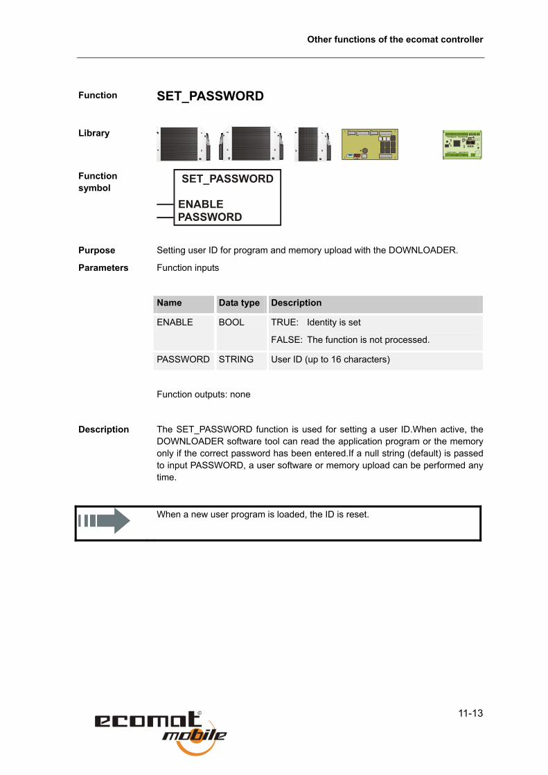
Other functions of the ecomat controller
11-13
Function
SET_PASSWORD
Library
Function symbol
Purpose Setting user ID for program and memory upload with the DOWNLOADER.
Parameters Function inputs
Name Data type Description
ENABLE BOOL TRUE: Identity is set
FALSE: The function is not processed.
PASSWORD STRING User ID (up to 16 characters)
Function outputs: none
Description The SET_PASSWORD function is used for setting a user ID.When active, theDOWNLOADER software tool can read the application program or the memoryonly if the correct password has been entered.If a null string (default) is passedto input PASSWORD, a user software or memory upload can be performed anytime.
When a new user program is loaded, the ID is reset.

Data access and verification
11-14
Function
CHECK_DATA
Library
Function symbol
Purpose Saving data in the user data memory through a CRC code.
Parameters Function inputs
Name Data type Description
STARTADR DINT Start address of the monitored memory (address from %MW0)
LENGTH WORD Length of monitored memory in bytes
UPDATE BOOL TRUE: Data changes permissible
FALSE: Data changes not permissible
Function outputs
Name Data type Description
RESULT BOOL TRUE: CRC checksum OK
FALSE: CRC checksum incorrect
Description The CHECK_DATA function monitors a memory range (possible addressesfrom %MW0) for unauthorised data modifications in applications requiring ahigh level of security. It does this by forming a CRC checksum for the specifieddata range.
When data is modified without authorisation, RESULT changes to FALSE. Theresult can then be used for further actions (for example disabling the outputs).The UPDATE input must be set FALSE in this case.
Data modifications (for example through the user program or PDM360) arepermitted only when input UPDATE is TRUE.The checksum is thenrecalculated. Output RESULT is then permanently set TRUE.

Other functions of the ecomat controller
11-15
The start address (type WORD, for example %MW0, because the functionworks only word-wise) must be passed to the function through address operatorADR. In addition, the number of data bytes (LENGTH – length fromSTARTADR) must be specified.
This is a safety function. Its use does not, however, automatically turn acontroller in which it is used into a safety controller. Only approved, testedcontrollers with a special operating system can be used as safety controllers.

Processing interrupts
11-16
11.4. Processing interrupts Function
SET_INTERRUPT_XMS
Library
Function symbol
Purpose Running a program block at an x ms interval.
Parameters Function inputs
Name Data type Description
ENABLE BOOL TRUE: Data changes permissible (Call once for initialisation)
FALSE: Data changes not permissible (during program run)
REPEATTIME TIME Time window in which the interrupt is triggered
READ_INPUTS BOOL TRUE: Inputs included in the routine are read (Set inputs to IN_FAST, if necessary)
FALSE: Inputs included in the routine are not read
WRITE_OUTPUTS BOOL TRUE: Outputs included in the routine are written to
FALSE: Outputs included in the routine are not written to
ANALOG_INPUTS BYTE (only for units with analog channels)
Selection of bit-coded inputs:
0 No input selected 1 1. Analog input (0b0000 0001) 2 2. Analog input (0b0000 0010)
........ 8 8. Analog input (0b1000 0000) A combination of inputs results from performing an AND operation on the values.

Other functions of the ecomat controller
11-17
Function outputs: none
Description In conventional PLCs, the timebase for real-time processes is provided by thecycle time. This puts PLCs at a disadvantage compared to custom controllers.Even a real-time operating system does not change this fact if the wholeapplication program runs in a single task.
One solution is to keep the cycle time short. This often results in the application being split up over several control cycles, which makes programming more difficult.
An other possibility is to call a particular program block at fixed intervals (here every x ms) independently of the control cycle.
The user can group the time-critical part of the application in a single block of the PROGRAM (PRG) type. This block is then declared as an interrupt routine with a one-off call of the SET_INTERRUPT_XMS function during initialisation. This program block is then always called after expiry of the REPEATTIME (every x ms). To prevent it being called at cycle time intervals as well, it must be skipped in the cycle time (except during initialisation). If inputs and outputs are used in this program block, they are also read and written to at the specified interval. Reading and writing can be suppressed with functions READ_INPUTS, WRITE_OUTPUTS and ANALOG_INPUTS.
Within the program block, all time-critical events can then be processed, by combining inputs or global variables and writing to outputs. This allows more precise monitoring of timers than is possible with PLC clock cycles.
Several timer interrupt blocks can be active. The time required by the interrupt functions must be calculated so that all called functions can be executed. This applies especially to calculations, floating-point arithmetic and controller functions.
Please note: The set REPEATTIME can vary in the case of high CAN bus activity.
The interrupt routine prevents a unique identification of the inputs and outputs within the cycle. Only some of them is therefore processed.
Inputs: Digital %IX0.12 – %IX0.15, %IX1.4 – %IX1.8 (Controller) %IX0.0, %IX0.8 (SmartController) IN08 – IN11 (CabinetController)
IN0 – IN3 (CS0015)
Analog All channels (selection bit-coded)
Outputs: Digital %QX0.0 – %QX0.7 (Controller) %QX0.0, %QX0.8 (SmartController) OUT0 – OUT3 (CabinetController)
OUT0 – OUT7 (CS0015)

Processing interrupts
11-18
All other inputs and outputs are processed at the PLC clock pulse interval as usual. The same applies to global variables if they are accessed at the same time in the PLC cycle and through the interrupt routine. This affects especially larger data types, such as DINT.

Other functions of the ecomat controller
11-19
Function
SET_INTERRUPT_I
Library
Function symbol
Purpose Executing a program part by means of an interrupt request via an input channel
Parameters Function inputs
Name Data type Description
ENABLE BOOL TRUE: Data changes permissible (call once for initialisation)
FALSE: Data changes not permissible
(during program run) CHANNEL BYTE Interrupt input
Classic/ExtC: 0 = %IX1.4 1 = %IX1.5
2 = %IX1.6 3 = %IX1.7
SmartC: 0 = %IX0.0 1 = %IX0.8
CabinetC: 0 = IN8 ... 3 = IN11
CS0015: 0 = IN0 ... 3 = IN3
MODE BYTE Type of edge at input CHANNEL that triggers the interrupt
1 = rising edge 2 = falling edge
3 = rising and falling edge
READ_INPUTS BOOL TRUE: Inputs included in the routine are read (Set inputs to IN_FAST, if necessary)
FALSE: Inputs included in the routine are not read
WRITE_OUTPUTS BOOL TRUE: Outputs included in the routine are

Processing interrupts
11-20
written to
FALSE: Outputs included in the routine are not written to
ANALOG_INPUTS BYTE (only for units with analog channels)
Selection of bit-coded inputs:
0 No input selected 1 1. Analog input (0b0000 0001) 3 2. Analog input (0b0000 0010)
........ 8 8. Analog input (0b1000 0000) A combination of inputs results from performing an AND operation on the values.
Function outputs: none
Description In conventional PLCs, the timebase for real-time processes is provided by thecycle time. This puts PLCs at a disadvantage compared to custom controllers.Even a real-time operating system does not change this fact if the wholeapplication program runs in a single task.
One solution is to keep the cycle time short. This often results in the application being split up over several control cycles, which makes programming more difficult.
It is also possible to call a certain program part independent of the control cycle on request of an input pulse.
The user can group the time-critical part of the application in a single block of the PROGRAM (PRG) type. This block is then declared as an interrupt routine with a one-off call of the SET_INTERRUPT_I function during initialisation. As a result this program block is always executed when an edge is detected at input CHANNEL. To prevent it being called at cycle time intervals as well, it must be skipped in the cycle time (except during initialisation). If inputs and outputs are used in this program part they are also read or written in the interrupt routine triggered by the input edge. Reading and writing can be suppressed with functions READ_INPUTS, WRITE_OUTPUTS and ANALOG_INPUTS.
Within the program block, all time-critical events can then be processed, by combining inputs or global variables and writing to outputs. Thus, functions can only be executed when requested by an input signal.

Other functions of the ecomat controller
11-21
The interrupt routine prevents a unique identification of the inputs and outputs within the cycle. Only some of them is therefore processed. If initialised in the interrupt program the following inputs and outputs are read or written.
Inputs: Digital %IX0.12 – %IX0.15, %IX1.4 – %IX1.8 (Controller) %IX0.0, %IX0.8 (SmartController) IN08 – IN11 (CabinetController)
IN0 – IN3 (CS0015)
Analog All channels (selection bit-coded)
Outputs: Digital %QX0.0 – %QX0.7 (Controller) %QX0.0, %QX0.8 (SmartController) OUT0 – OUT3 (CabinetController)
OUT0 – OUT7 (CS0015)
The input (CHANNEL) that is monitored for triggering the interrupt cannot be initialised and further processed in the interrupt routine.
All other inputs and outputs are processed at the PLC clock pulse interval as usual. The same applies to global variables if they are accessed at the same time in the PLC cycle and through the interrupt routine. This affects especially larger data types, such as DINT.

Sending data through the built-in SSC interface.
11-22
11.5. Sending data through the built-in SSC interface. Function
SSC_RECEIVE
Library
Function symbol
Purpose Receiving data through the built-in SSC interface.
Parameters Function inputs
Name Data type Description
ENABLE BOOL TRUE: Function is active
FALSE: Function is not active
Function outputs
Name Data type Description
RX ARRAY Array [0..19]
VALID BOOL New data has been transmitted. The output is TRUE for one cycle.
OVER-FLOW
BOOL TRUE : The message received could not be entered in the receive buffer.
Description SSC_RECEIVE is an internal communication function for the
ExtendedController. Each time it is called, it reads the transferred data bytes (upto 16 messages with 20 bytes/control cycles) from the receive buffer. Functioninput ENABLE must set TRUE. When new, valid data has been transmitted,output VALID is set TRUE for one cycle.

Other functions of the ecomat controller
11-23
The user program must read the received data from the array straight away, since it will be overwritten again in the next cycle.
Note that the number of messages that can be sent with SSC_TRANSMIT is limited to the number that the other half of the controller can receive. Otherwise data may be lost, for example due to the different cycle times.
An overflow for the function block SSC_RECEIVE may occur if the receiver is the interface slave and if the interface master is running faster (error bit: OVERFLOW).

Sending data through the built-in SSC interface.
11-24
Function
SSC_TRANSMIT
Library
Function symbol
Purpose Sending data through the built-in SSC interface.
Parameters Function inputs
Name Data type Description
ENABLE BOOL TRUE: Function is active
FALSE: Function is not active
TX ARRAY Array [0..19]
Function outputs
Name Data type Description
RESULT BOOL TRUE: The message was successfully transferred to the transmission buffer.
Description SSC_TRANSMIT is an internal communication function for theExtendedController. Each time it is called, it sends the data contained in arrayTX. Up to 16 messages of 20 bytes each can be transmitted per control cycle.Function input ENABLE must set TRUE for transmission to take place.
The user program must read the received data from the array straight away, since it will be overwritten again in the next cycle.
Note that the number of messages that can be sent with SSC_TRANSMIT is limited to the number that the other half of the controller can receive. Otherwise data may be lost, for example due to the different cycle times.
An overflow for SSC_TRANSMIT may occur if the receiver is the interface slave and if the interface master is running slower. (Information bit: RESULT=FALSE)

Other functions of the ecomat controller
11-25
Function
SSC_SET_MASTER
Library
Function symbol
Purpose Activating master/slave operation of the ExtendedController.
Parameters Function inputs
Name Data type Description
ENABLE BOOL TRUE: Function is active
FALSE: Function is not active
Function outputs
Name Data type Description
RESULT BYTE 0: Not active (SSC_NO_WORKING) 1: Data transmission completed (SSC_DONE) 2: Function active (transmission in progress) (SSC_BUSY) 3: Error, data can not be sent (SSC_ERROR)
Description SSC_SET_MASTER is an internal communication function for theExtendedController. It initialises master/slave control mode. The inputs andoutputs are processed synchronously. The master also loads a small dummyprogram into the slave. This program block from slave library SLAVE200.LIBmust be included in the application program.
To distinguish the I/O level 2 system variables and functions from those of level1, an _E (for Extended) is appended to their name. The data transfer betweenthe two controller sections takes place automatically through the built-ininterface.

Sending data through the built-in SSC interface.
11-26
The user program must read the received data from the array straight away, since it will be overwritten again in the next cycle.
Note that the number of messages that can be sent with SSC_TRANSMIT is limited to the number that the other half of the controller can receive. Otherwise data may be lost, for example due to the different cycle times.
The example shows the basic program structure with initialisation, inclusion of the dummy program (function block DUMMY) and two functions that are executed in the slave module (–_E). To maintain the timed execution sequence during initialisation, use the structure of the example for your application program.

Other functions of the ecomat controller
11-27
11.6. Using the serial interface
Function
SERIAL_SETUP
Library
Function symbol
Purpose Initialises the serial RS 232 interface.
Parameters Function inputs
Name Data type
Description
ENABLE BOOL TRUE: Interface is initialised
FALSE: Function is not active
BAUDRATE BYTE Baud rate (permissible values: 9600, 19200, 28800, 57600)
DATABITS BYTE Data bits (permissible values: 7 and 8)
PARITY BYTE Parity (permissible values: 0: none, 1: even, 2: odd)
STOPBITS BYTE Stop bits (permissible values: 1 and 2)
Function outputs; None
Description SERIAL_SETUP initializes the specified settings for the serial port. With function input ENABLE, the function is activated for one cycle.
The SERIAL functions form the basis for creating a custom protocol for the serial interface.

Using the serial interface
11-28
The serial interface is not normally available to the user, since it is used for downloading programs and for debugging. To use the interface, set system marker bit SERIAL_MODE to TRUE. You will then have to use the CAN interface for program downloads and debugging.

Other functions of the ecomat controller
11-29
Function
SERIAL_TX
Library
Function symbol
Purpose Transmits a data byte through the serial RS 232 interface.
Parameters Function inputs
Name Data type Description
ENABLE BOOL TRUE: Enable transmission
FALSE: Disable transmission
DATA BYTE Byte data to be transferred
Function outputs; None
Description SERIAL_TX transfers the DATA byte through the serial interface. Transmission can be enabled and inhibited with function input ENABLE.
The SERIAL functions form the basis for creating a custom protocol for the serial interface.
The serial interface is not normally available to the user, since it is used for downloading programs and for debugging. To use the interface, set system marker bit SERIAL_MODE to TRUE. You will then have to use the CAN interface for program downloads and debugging.

Using the serial interface
11-30
Function
SERIAL_RX
Library
Function symbol
Purpose Reads a received data byte from the serial receive buffer.
Parameters Function inputs
Name Data type Description
CLEAR BOOL TRUE: Receive buffer will be cleared
FALSE: Default state
Function outputs
Name Data type Description
RX BYTE Received byte data from the receive buffer
AVAILABLE WORD Number of received data bytes
AVAILABLE = 0, buffer contains no data
OVERFLOW BOOL Buffer overflow. Los of data!
Description SERIAL_RX reads a data byte from the serial receive buffer each time it is called. The value of AVAILABLE is counted down by 1 with each call. If the buffer contains no data, the value of AVAILABLE is 0.
The buffer’s capacity is 1000 bytes; if more data is received, data will be lost and the OVERFLOW bit is set.
The SERIAL functions form the basis for creating a custom protocol for the serial interface.

Other functions of the ecomat controller
11-31
Example:
3 bytes are received:
1st call of SERIAL_RX 1 valid date at output RX AVAILABLE = 32nd call of SERIAL_RX 1 valid date at output RX AVAILABLE = 23rd call of SERIAL_RX 1 valid date at output RX AVAILABLE = 14th call of SERIAL_RX invalid date at output RX AVAILABLE = 0 If AVAILABLE = 0 the function can be skipped in the program run.
The serial interface is not normally available to the user, since it is used for downloading programs and for debugging. To use the interface, set system marker bit SERIAL_MODE to TRUE. You will then have to use the CAN interface for program downloads and debugging.
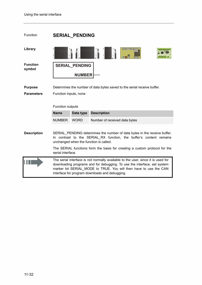
Using the serial interface
11-32
Function
SERIAL_PENDING
Library
Function symbol
Purpose Determines the number of data bytes saved to the serial receive buffer.
Parameters Function inputs, none
Function outputs
Name Data type Description
NUMBER WORD Number of received data bytes
Description SERIAL_PENDING determines the number of data bytes in the receive buffer. In contrast to the SERIAL_RX function, the buffer’s content remains unchanged when the function is called.
The SERIAL functions form the basis for creating a custom protocol for the serial interface.
The serial interface is not normally available to the user, since it is used for downloading programs and for debugging. To use the interface, set system marker bit SERIAL_MODE to TRUE. You will then have to use the CAN interface for program downloads and debugging.

Other functions of the ecomat controller
11-33
11.7. Reading the system time Function
TIMER_READ
Library
Function symbol
Purpose Reads the current system time.
Parameters Function inputs, none
Function output
Name Data type Description
T TIME Current system time (resolution ms)
Description When the supply voltage is applied, an internal clock pulse is generated and a register is incremented. This register can be read with the TIMER_READ function, for example for measuring time.
When the system timer reaches 0xFFFF FFFF (corresponds with about 49.7 days) it restarts at 0.

Reading the system time
11-34
Function
TIMER_READ_US
Library
Function symbol
Purpose Reads the current system time in microseconds.
Parameters Function inputs, none
Function outputs
Name Data type Description
TIME_US DWORD Current system time in microseconds
Description When the supply voltage is applied, an internal clock pulse is generated and a register is incremented. This register can be read with the TIMER_READ function, for example for measuring time.
When the system timer reaches 4294967295 (μs), it starts again at zero.

Other functions of the ecomat controller
11-35
11.8. Processing variables
Function
NORM
Library
Function symbol
Purpose Normalises a value within specified limits to a value with new limits.
Parameters Function inputs
Name Data type Description
x WORD Output value
XH WORD Upper limit of input value range
XL WORD Lower limit of input value range
YH WORD Upper limit of output value range
YL WORD Lower limit of output value range
Function outputs
Name Data type Description
Y WORD Standardised data of type WORD
Description The NORM function normalises a value of type WORD that lies within limits XHand XL to an output value within limits YH and YL. This function can be used,for example, for creating PWM values from analog input values.

Processing variables
11-36
Example Non-normalised value: 50 *
Lower limit value of input: 0
Upper limit value of input: 100
Lower limit value of output: 0
Upper limit value of output: 2000
Standardised value: 1000
* The value of X must lie between XL and XH (the values are not internally checked for validity).
The rounding error can result in deviations about the normalised value about 1. If inverted limits (XH/XL or YH/YL) are specified, the normalisation is also inverted.

Other functions of the ecomat controller
11-37
11.9. Processing analog values
Function
INPUT_VOLTAGE
Library
Function symbol
Purpose Measures voltage at the analog channels.
Parameters Function inputs
Name Data type Description
ENABLE BOOL TRUE: The function is processed
FALSE: The function is not processed.
MODE_ 10V_32V
BOOL TRUE: Voltage range 0 – 32 V
FALSE: Voltage range 0 – 10 V
INPUT_ CHANNEL
BYTE Input channel
Function outputs
Name Data type Description
ACTUAL_ VOLTAGE
WORD Output voltage in mV
Description This function returns the current input voltage in mV at the selected analogchannel. The reading relates to the voltage range (10,000 mV or 32,000 mV)specified with MODE_10V_32V.
INPUT_VOLTAGE is a compatibility function for older programs. In new programs, use the more powerful INPUT_ANALOG function.

Processing analog values
11-38
Function
INPUT_CURRENT
Library
Function symbol
Purpose Reads the analog current inputs.
Parameters Function inputs
Name Data type Description
ENABLE BOOL TRUE: The function is processed
FALSE: The function is not processed.
INPUT_ CHANNEL
BYTE Analog current inputs 4 – 7
ACTUAL_ CURRENT
WORD Input current in µA
Description This function returns the current input current in µA at the analog current inputs.
INPUT_CURRENT is a compatibility function for older programs. In new programs, use the more powerful INPUT_ANALOG function.

Other functions of the ecomat controller
11-39
Function
INPUT_ANALOG
Library
Function symbol
Purpose Current/voltage measurement at the analog channels.
Parameters Function inputs
Name Data type Description
ENABLE BOOL TRUE: The function is processed
FALSE: The function is not processed.
MODE
BYTE IN_DIGITAL_H Digital input
IN_CURRENT Current input 0 – 20000 μA
IN_VOLTAGE10 Voltage input 0 – 10000 mV
IN_VOLTAGE30 Voltage input 0 – 30000 mV/ IN_VOLTAGE32 Voltage input 0 – 32000 mV
IN_RATIO Ratiometric analog input
INPUT_ CHANNEL
BYTE Input channel
Function outputs
Name Data type Description
OUT WORD Output value
Description This function returns the current analog value at the selected analog channel.The reading and the output value result from the mode (digital input, 0 – 20 mA,0 – 10 V, 0 – 30 V) specified with MODE. Use the above global systemvariables for setting the mode. The analog values are output as standardisedvalues.

Processing analog values
11-40

12-1
12. Closed-loop control functions in the ecomat controller In closed-loop control, controller continually reads the value of the controlled variable, compares it with a reference input variable and – if there is a difference between the two values – adjusts the controlled variable accordingly.
To select and set up a suitable controller, you will need detailed information about the steady-state behaviour and the dynamic behaviour of the controlled system. In most cases, these characteristics can only be determined by experiment.
Controlled systems can be broadly split into three types:
Controlled systems with compensation
In controlled systems with compensation, the controlled variable (x) tendstowards a new steady-state target value after a change in the manipulatedvariable. In these controlled system, the gain (transfer coefficient KS) plays adecisive role: the smaller the gain, the better controllable is the system.
This type of controlled system is called proportional (or P) system.

Processing analog values
12-2
Controlled systems without compensation
Controlled systems with a gain factor tending towards infinity, are known asuncompensated controlled systems. This is usually due to an integratingbehaviour, which results in a steady rise of the controlled variable after achange in the manipulated variable or due to disturbance. This means that thetarget value is never reached.
This type of controlled system is called integral (or I) system.
Controlled systems with lag
Most controlled systems consist of P systems and one or more T1 systems(systems with lag). A first-order controlled system consists for example of achoke upstream of a series-connected vessel.
In controlled systems with delay, the controlled variable responds to a change in the manipulated variable only after the delay time Tt has expired. Delay Tt or the sum of Tt and Tu determines the controllability of the system: the higher the ratio Tg/Tu, the better controllable is the system.
The controllers containing the library combine the above basic functions. Which combination of functions you use will depend on your controlled system.

Closed-loop control functions in the ecomat controller
12-3
12.1. Setting method for closed-loop controllers For controlled systems whose time constants are not known, the setting procedure according to Ziegler and Nickols in the closed control circuit is recommended.
Setting method Initially, the controlling system is operated as a pure P controller. For a systemwith lag, set the rate time TV to 0 and the reset time TN to a large value (ideally∞). For a fast controlled system, choose a low value for TN. Then increase theproportional coefficient KP until the system deviation at KP = KPcrit oscillates atconstant amplitude. The stability limit is now reached. Then determine theperiod duration Tcrit of the oscillation. Only if necessary add a D (derivative)component. TV should be about 2 to 10 times less than TN and KP = KD.
The ideal settings would be as follows:
Controller setting
KP = KD TN TV
P 2.0 x KPcrit - -
PI 2.2 x KPcrit 0.83 x Tcrit -
PID 1.7 x KPcrit 0.50 x Tcrit 0.125 x Tcrit
When you use this setting method, make sure that the oscillations do not damage the controlled system. In sensitive controlled systems, do not increase KP to a value at which oscillation may occur.
Damping overshoot
To dampen overshoot, you can use the PT1 (low-pass) function. This uses the P-T1 element to dampen the setpoint value XS before passing it to the controller function. T1 should be about 4 to 5 times larger than TN (of the PID or GLR controller).
12.2. Controller function blocks This section provides a detailed description of the functions used to create software controllers within the control system. You can also use them as a basis for developing your own control functions.

Controller function blocks
12-4
Function
DELAY
Library
Function symbol
Purpose Delays the output of the input value by time T (lag element).
Parameters Function input
Name Data type Description
x WORD Input value
T TIME Delay
Function outputs
Name Data type Description
Y WORD Input value delays by time T
Description Function DELAY is used to delay an input value by time T.
Output variable y has the following time characteristic:
To work correctly, this function must be called in every cycle.

Closed-loop control functions in the ecomat controller
12-5
Function
PT1
Library
Function symbol
Purpose Controlled system with first-order delay.
Parameters Function inputs
Name Data type Description
x INT Input value
T1 TIME Delay time
Function outputs
Name Data type Description Y INT Output variable
Description Function PT1 is a proportional system with one time constant. It is used, forexample, to form ramps when using the PWM functions.
Output variable y of the low-pass filter has the following unit step response:

Controller function blocks
12-6
Function
PID1
Library
Function symbol
Purpose PID control.
Parameters Function inputs
Name Data type Description
x WORD Actual value
XS WORD Setpoint value
XMAX WORD Maximum setpoint value
KP BYTE Constant of the P component
KI BYTE I component
KD BYTE Proportional component of the D component
Function outputs
Name Data type Description
Y WORD Manipulated variable
Description The changes in the manipulated variable of a PID controller consists of aproportional, an integral and a differential component. The manipulated variableinitially changes by an amount that depends on the rate of change of the inputvariable (D component). After expiry of rate time TV, the manipulated variablegoes back to the value corresponding to the proportional range and thenchanges according to the reset time.

Closed-loop control functions in the ecomat controller
12-7
Variable Y is already normalised to the PWM function (RELOAD value = 65535). Observe the inverse logic (65535 = lowest value, 0 = largest value).
When X > XS, the variable increases.
When X < XS, the variable reduces.
Variable y has the following time characteristic:
Typical step response of a PID controller

Controller function blocks
12-8
Recommended settings
• KP = 50
• KI = 30
• KD = 5
With the values specified above, control is both fast and stable withoutoscillations.
To optimise control performance, you can then change the values in steps.
Note that input variables KI and KD are dependent on the cycle time. For stable, reproducible control performance, call PID1 under time control.

Closed-loop control functions in the ecomat controller
12-9
Function
PID2
Library
Function symbol
Purpose PID control.
Parameters Function inputs
Name Data type Description
x WORD Actual value
XS WORD Setpoint value
XMAX WORD Maximum setpoint value
KP BYTE Constant of the P component (/10)
TN TIME Reset time (I component)
KD BYTE Proportional component of the D component (/10)
TV TIME Rate time (D component)
SO BOOL Self-optimisation
Reset BOOL Resets a function
Function outputs
Name Data type Description
Y WORD Manipulated variable
Controller function blocks
12-10
Description The changes in the manipulated variable of a PID controller consists of aproportional, an integral and a differential component. The manipulated variableinitially changes by an amount that depends on the rate of change of the inputvariable (D component). After expiry of rate time TV, the manipulated variablegoes back to the value corresponding to the proportional range and thenchanges according to the reset time TN.
The values entered at function inputs KP and KD are internally divided by 10 to achieve a higher resolution (e.g. KP = 17 means 1.7).
Variable Y is already normalised to the PWM function (RELOAD value = 65535). Observe the inverse logic (65535 = lowest value, 0 = largest value).
When X > XS, the variable increases.
When X < XS, the variable reduces.
A reference input variable is internally added to the value of the manipulated variable:
Y = Y + 65536 – (XS / XMAX x 65536).

Closed-loop control functions in the ecomat controller
12-11
Variable y has the following time characteristic:
Typical step response of a PID controller

Controller function blocks
12-12
Recommended settings
• Select TN according to the system’s time response (fast system: small TN;slow system: high TN)
• Gradually increase KP in small steps up to a value at which no oscillationswill yet occur.
• If necessary, adjust TN.
• Only if necessary add a D component, selecting a value for TV about 2 to10 times smaller than TN and set KD approximately to the value of KP.
Note that the maximum control deviation is +/- 127. For a good controlperformance, utilise this range as fully as possible without actually exceeding it.
Function input SO (self-optimisation) clearly improves the control performance.A precondition for achieving the desired characteristics:
• The controller is operated with I component (TN ≥ 50 ms)
• Parameters KP and especially TN are already well adjusted to the actualcontrolled system.
• The control range (X – XS) of +/- 127 is utilised (if necessary, increase thecontrol range by multiplying X, XS and XMAX).
When you have finished setting the parameters, you can set SO = TRUE. Thiswill significantly improve the control performance, especially reducingovershoot.
Example PI controller in a simulated system.
SO = FALSE

Closed-loop control functions in the ecomat controller
12-13
SO = TRUE
Overshooting does not occur.
Example
Speed control with PID controller
Features:
• Double control range spread
• Self-optimisation
• Adaptation of controller output Y to a PWM function block. Adaptation of TNto the relatively slow system behaviour (rotating mass).
• Despite the D component, overshoot is relatively low.
Special feature The motor in the example already reaches its maximum speed at 20 % PWM.Function module NORM takes this into account.
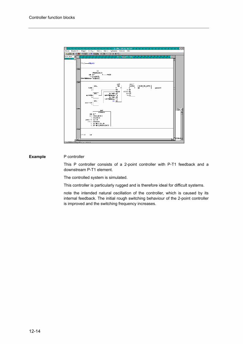
Controller function blocks
12-14
Example P controller
This P controller consists of a 2-point controller with P-T1 feedback and adownstream P-T1 element.
The controlled system is simulated.
This controller is particularly rugged and is therefore ideal for difficult systems.
note the intended natural oscillation of the controller, which is caused by itsinternal feedback. The initial rough switching behaviour of the 2-point controlleris improved and the switching frequency increases.

Closed-loop control functions in the ecomat controller
12-15

Controller function blocks
12-16
Function
GLR
Library
Function symbol
Purpose Synchro control.
Parameters Function inputs
Name Data type Description
X1 WORD Actual value, channel 1
X2 WORD Actual value, channel 2
XS WORD Setpoint value = reference input variable
XMAX WORD Maximum setpoint value
KP BYTE Constant of the P component (/10)
TN TIME Reset time (I component)
KD BYTE Proportional component of the D component (/10)
TV TIME Rate time (D component)
Function outputs
Name Data type Description
Y1 WORD Manipulated variable, channel 1
Y2 WORD Manipulated variable, channel 2

Closed-loop control functions in the ecomat controller
12-17
Description The synchro-controller is a controller with PID behaviour.
The values entered at function inputs KP and KD are internally divided by 10 to achieve a higher resolution (e.g. KP = 17 means 1.7).
Variables Y1 and Y2 are already normalised to the PWM function (RELOAD value = 65535). Observe the inverse logic (65535 = lowest value, 0 = largest value).
The manipulated variable for the higher actual value is increased, while the variable for the smaller actual value corresponds to the reference variable.
Reference variable = 65536 – (XS / XMAX x 65536).

Controller function blocks
12-18
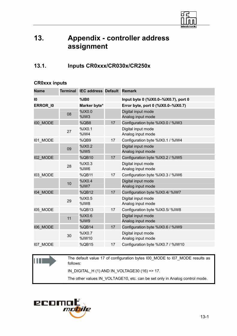
13-1
13. Appendix - controller address assignment
13.1. Inputs CR0xxx/CR030x/CR250x
CR0xxx inputs Name Terminal IEC address Default Remark
I0 %IB0 Input byte 0 (%IX0.0–%IX0.7), port 0 ERROR_I0 Marker byte* Error byte, port 0 (%IX0.0–%IX0.7) 08 %IX0.0
%IW3 Digital input mode
Analog input mode I00_MODE %QB8 17 Configuration byte %IX0.0 / %IW3 27 %IX0.1
%IW4 Digital input mode
Analog input mode I01_MODE %QB9 17 Configuration byte %IX0.1 / %IW4 09 %IX0.2
%IW5 Digital input mode
Analog input mode I02_MODE %QB10 17 Configuration byte %IX0.2 / %IW5 28 %IX0.3
%IW6 Digital input mode
Analog input mode I03_MODE %QB11 17 Configuration byte %IX0.3 / %IW6 10 %IX0.4
%IW7 Digital input mode
Analog input mode I04_MODE %QB12 17 Configuration byte %IX0.4/ %IW7 29 %IX0.5
%IW8 Digital input mode
Analog input mode I05_MODE %QB13 17 Configuration byte %IX0.5/ %IW8 11 %IX0.6
%IW9 Digital input mode
Analog input mode I06_MODE %QB14 17 Configuration byte %IX0.6 / %IW9 30 %IX0.7
%IW10 Digital input mode
Analog input mode I07_MODE %QB15 17 Configuration byte %IX0.7 / %IW10
The default value 17 of configuration bytes I00_MODE to I07_MODE results as follows:
IN_DIGITAL_H (1) AND IN_VOLTAGE30 (16) => 17.
The other values IN_VOLTAGE10, etc. can be set only in Analog control mode.

13-2
Name Terminal IEC address Default Remark
I1 %IB1 Input byte 1 (%IX0.8–%IX0.15), port 1 ERROR_I1 Marker byte* Error byte, port 1 (%IX0.8–%IX0.15) 44 %IX0.8 Digital input mode 45 %IX0.9 Digital input mode 46 %IX0.10 Digital input mode 47 %IX0.11 Digital input mode 20 %IX0.12 Digital input mode/fast input FRQ0 I14_MODE %QB16 1 Configuration byte %IX0.12 02 %IX0.13 Digital input mode/fast input FRQ1 I15_MODE %QB17 1 Configuration byte %IX0.13 21 %IX0.14 Digital input mode/fast input FRQ2 I16_MODE %QB18 1 Configuration byte %IX0.14 38 %IX0.15 Digital input mode/fast input FRQ3 I17_MODE %QB19 1 Configuration byte %IX0.15 I2 %IB2 Input byte 2 (%IX1.0–%IX1.7), port 2 ERROR_I2 Marker byte* Error byte, port 2 (%IX1.0–%IX1.7) 36 %IX1.0 Digital input mode 54 %IX1.1 Digital input mode 17 %IX1.2 Digital input mode 53 %IX1.3 Digital input mode 19 %IX1.4 Digital input mode/fast input CYL0 I24_MODE %QB20 1 Configuration byte %IX1.4 55 %IX1.5 Digital input mode/fast input CYL1 I25_MODE %QB21 1 Configuration byte %IX1.5 18 %IX1.6 Digital input mode/fast input CYL2 I26_MODE %QB22 1 Configuration byte %IX1.6 37 %IX1.7 Digital input mode/fast input CYL3 I27_MODE %QB23 1 Configuration byte %IX1.7

Appendix - controller address assignment
13-3
Name Terminal IEC address Default Remark
I3 %IB3 Input byte 3 (%IX1.8–%IX1.15), port 3
ERROR_I3 Marker byte* Error byte, port 3 (%IX1.8–%IX1.15) 39 %IX1.8 Digital input mode I30_MODE %QB24 1 Configuration byte %IX1.8 03 %IX1.9 Digital input mode I31_MODE %QB25 1 Configuration byte %IX1.9 40 %IX1.10 Digital input mode I32_MODE %QB26 1 Configuration byte %IX1.10 22 %IX1.11 Digital input mode I33_MODE %QB27 1 Configuration byte %IX1.11 41 %IX1.12 Digital input mode I34_MODE %QB28 1 Configuration byte %IX1.12 42 %IX1.13 Digital input mode I35_MODE %QB29 1 Configuration byte %IX1.13 43 %IX1.14 Digital input mode I36_MODE %QB30 1 Configuration byte %IX1.14 04 %IX1.15 Digital input mode I37_MODE %QB31 1 Configuration byte %IX1.15 I4 %IB4 Input byte 4 (%IX2.0–%IX2.7), port 4 ERROR_I4 Marker byte* Error byte, port 4 (%IX2.0–%IX2.7) 48 %IX2.0 Digital input mode I40_MODE %QB32 1 Configuration byte %IX2.0 49 %IX2.1 Digital input mode I41_MODE %QB33 1 Configuration byte %IX2.1 31 %IX2.2 Digital input mode I42_MODE %QB34 1 Configuration byte %IX2.2 50 %IX2.3 Digital input mode I43_MODE %QB35 1 Configuration byte %IX2.3 51 %IX2.4 Digital input mode I44_MODE %QB36 1 Configuration byte %IX2.4 52 %IX2.5 Digital input mode I45_MODE %QB37 1 Configuration byte %IX2.5 16 %IX2.6 Digital input mode I46_MODE %QB38 1 Configuration byte %IX2.5 35 %IX2.7 Digital input mode I47_MODE %QB39 1 Configuration byte %IX2.7
13-4
Note for input byte I4 (%IX2.0–%QX2.7)
Only when the corresponding output channel in output byte 4 is disabled (OUT_NOMODE) can the corresponding input in input byte I4 be used.
Note for ExtendedController
Symbolic names with suffix _E (for example ANALOG0_E) denote system addresses in the ExtendedController’s slave module. They have the same functions as the addresses in the master module.
Possible control modes, inputs CR0xxx:
Byte I0, 0 – 7 IN_NOMODE 0 IN_DIGITAL_H (plus) 1 (default) IN_CURRENT 4 IN VOLTAGE10 8 IN_VOLTAGE30 16 (default) IN_RATIO 32 IN_DIAGNOSIC 64 Byte I1 4 – 7 IN_NOMODE 0 IN_DIGITAL_H (plus) 1 (default) IN_DIAGNOSIC 64 IN_FAST 128 Byte I2 4 – 7 IN_NOMODE 0 IN_DIGITAL_H (plus) 1 (default) IN_DIGITAL_L (minus) 2 IN_DIAGNOSIC 64 IN_FAST 128 Byte I3 0 – 7 IN_NOMODE 0 IN_DIGITAL_H (plus) 1 (default) IN_DIGITAL_L (minus) 2 IN_DIAGNOSIC 64 Byte I4 0 – 7 IN_NOMODE 0 IN_DIGITAL_H (plus) 1 (default) IN_DIAGNOSIC 64 Possible configuration combinations are created by adding the values.
* Addresses can differ depending on controller configuration.

Appendix - controller address assignment
13-5
CR03xx inputs
Name Terminal IEC address Default Remark
ANALOG_ARRAY %IW13 Raw data analog conversion (not for application: evaluation through function block)
ANALOG0_4_MODE %QB30 Configuration byte, analog channels 0 and 4 X2.1 X2.7 Access to analogue values through function block
INPUT_ANALOG ERROR_A_IN0 Marker bit* Analog value 0 outside valid range ERROR_A_IN4 Marker bit* Analog value 4 outside valid range ANALOG1_5_MODE %QB31 Configuration byte, analog channels 1 and 5 X2.2 X2.8 Access to analogue values through function block
INPUT_ANALOG ERROR_A_IN1 Marker bit* Analog value 1 outside valid range ERROR_A_IN5 Marker bit* Analog value 5 outside valid range ANALOG2_6_MODE %QB32 Configuration byte, analog channels 2 and 6 X2.3 X2.9 Access to analogue values through function block
INPUT_ANALOG ERROR_A_IN2 Marker bit* Analog value 2 outside valid range ERROR_A_IN6 Marker bit* Analog value 6 outside valid range ANALOG3_7_MODE %QB33 Configuration byte, analog channels 3 and 7 X2.4
X2.10 Access to analogue values through function block
INPUT_ANALOG ERROR_A_IN3 Marker bit* Analog value 3 outside valid range ERROR_A_IN7 Marker bit* Analog value 7 outside valid range IN0 X4.1 %IX1.0 Digital input IN0 IN1 X4.2 %IX1.8 Digital input IN1 IN2 X4.3 %IX2.0 Digital input IN2 IN3 X4.4 %IX2.8 Digital input IN3 IN4 X4.5 %IX3.0 Digital input IN4 IN5 X4.6 %IX3.8 Digital input IN5 IN6 X4.7 %IX4.0 Digital input IN6 IN7 X4.8 %IX4.8 Digital input IN7 IN8 X4.11 %IX5.0 Digital input IN8/fast input FRQ0/CYL0 IN9 X4.12 %IX5.8 Digital input IN9/fast input FRQ1/CYL1 IN10 X4.13 %IX6.0 Digital input IN10/fast input FRQ2/CYL2 IN11 X4.14 %IX6.8 Digital input IN11/fast input FRQ3/CYL3 IN12 X4.15 %IX7.0 Digital input IN12 IN13 X4.16 %IX7.8 Digital input IN13 IN12_13_MODE %QB28 Configuration byte, inputs IN12 and IN13 IN14 X4.17 %IX8.0 Digital input IN14 IN15 X4.18 %IX8.8 Digital input IN15 IN14_15_MODE %QB29 Configuration byte, inputs IN12 and IN13
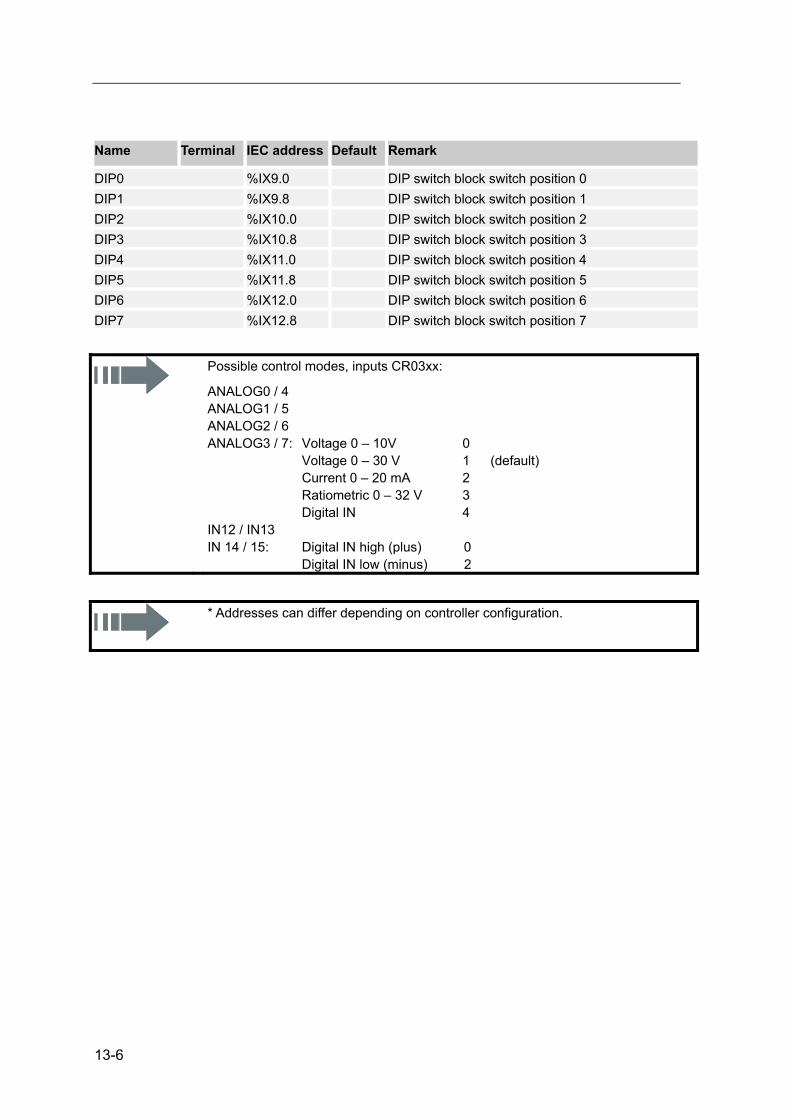
13-6
Name Terminal IEC address Default Remark
DIP0 %IX9.0 DIP switch block switch position 0 DIP1 %IX9.8 DIP switch block switch position 1 DIP2 %IX10.0 DIP switch block switch position 2 DIP3 %IX10.8 DIP switch block switch position 3 DIP4 %IX11.0 DIP switch block switch position 4 DIP5 %IX11.8 DIP switch block switch position 5 DIP6 %IX12.0 DIP switch block switch position 6 DIP7 %IX12.8 DIP switch block switch position 7
Possible control modes, inputs CR03xx:
ANALOG0 / 4 ANALOG1 / 5 ANALOG2 / 6 ANALOG3 / 7: Voltage 0 – 10V 0 Voltage 0 – 30 V 1 (default) Current 0 – 20 mA 2 Ratiometric 0 – 32 V 3 Digital IN 4 IN12 / IN13 IN 14 / 15: Digital IN high (plus) 0 Digital IN low (minus) 2
* Addresses can differ depending on controller configuration.
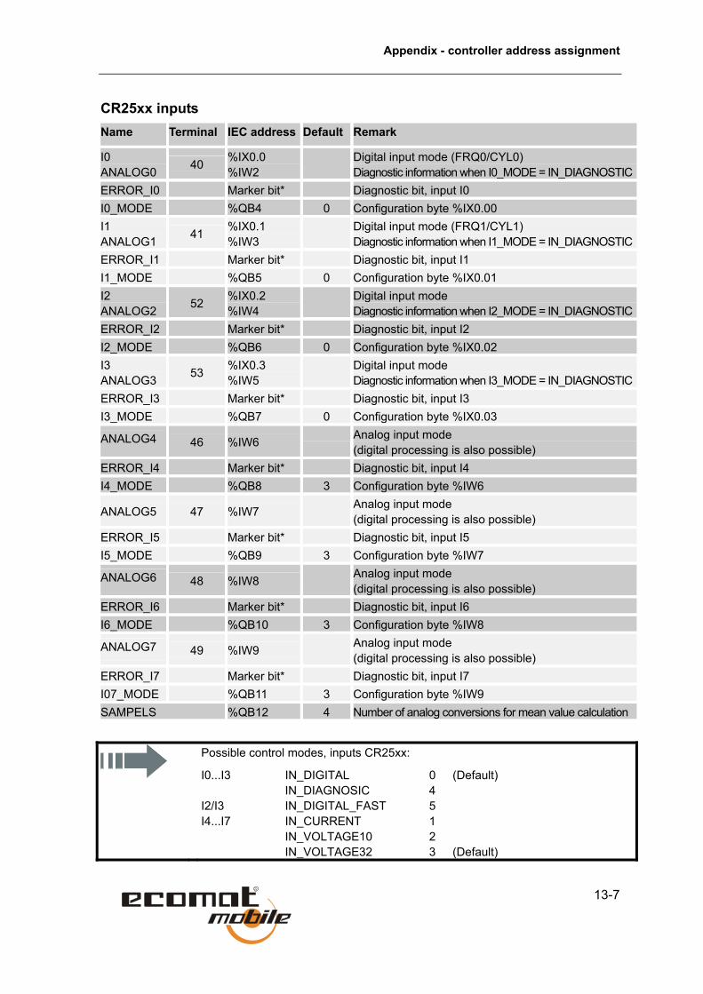
Appendix - controller address assignment
13-7
CR25xx inputs Name Terminal IEC address Default Remark
I0 ANALOG0 40 %IX0.0
%IW2 Digital input mode (FRQ0/CYL0)
Diagnostic information when I0_MODE = IN_DIAGNOSTICERROR_I0 Marker bit* Diagnostic bit, input I0 I0_MODE %QB4 0 Configuration byte %IX0.00 I1 ANALOG1 41 %IX0.1
%IW3 Digital input mode (FRQ1/CYL1)
Diagnostic information when I1_MODE = IN_DIAGNOSTICERROR_I1 Marker bit* Diagnostic bit, input I1 I1_MODE %QB5 0 Configuration byte %IX0.01 I2 ANALOG2 52 %IX0.2
%IW4 Digital input mode
Diagnostic information when I2_MODE = IN_DIAGNOSTICERROR_I2 Marker bit* Diagnostic bit, input I2 I2_MODE %QB6 0 Configuration byte %IX0.02 I3 ANALOG3 53 %IX0.3
%IW5 Digital input mode
Diagnostic information when I3_MODE = IN_DIAGNOSTICERROR_I3 Marker bit* Diagnostic bit, input I3 I3_MODE %QB7 0 Configuration byte %IX0.03
ANALOG4 46 %IW6 Analog input mode (digital processing is also possible)
ERROR_I4 Marker bit* Diagnostic bit, input I4 I4_MODE %QB8 3 Configuration byte %IW6
ANALOG5 47 %IW7 Analog input mode (digital processing is also possible)
ERROR_I5 Marker bit* Diagnostic bit, input I5 I5_MODE %QB9 3 Configuration byte %IW7
ANALOG6 48 %IW8 Analog input mode (digital processing is also possible)
ERROR_I6 Marker bit* Diagnostic bit, input I6 I6_MODE %QB10 3 Configuration byte %IW8
ANALOG7 49 %IW9 Analog input mode (digital processing is also possible)
ERROR_I7 Marker bit* Diagnostic bit, input I7 I07_MODE %QB11 3 Configuration byte %IW9 SAMPELS %QB12 4 Number of analog conversions for mean value calculation
Possible control modes, inputs CR25xx:
I0...I3 IN_DIGITAL 0 (Default) IN_DIAGNOSIC 4 I2/I3 IN_DIGITAL_FAST 5 I4...I7 IN_CURRENT 1 IN_VOLTAGE10 2
IN_VOLTAGE32 3 (Default)

13-8
13.2. Outputs CR0xxx / CR030x / CR250x
CR0xxx outputs Name Terminal IEC address Default Remark
Q1Q2 %QB0 Output byte 0 (%QX0.00–%QX0.07), port 1/2 ERROR_SHORT_Q1Q2 Marker byte* Error byte 1/2, short circuit (%QX0.00–%QX0.07)ERROR_BREAK_Q1Q2 Marker byte* Error byte 1/2, open circuit (%QX0.00–%QX0.07) 44 %QX0.0 Digital output mode Q10_MODE %QB40 1 Configuration byte %QX0.00 / PWM0 45 %QX0.1 Digital input mode Q11_MODE %QB41 1 Configuration byte %QX0.01 / PWM1 46 %QX0.2 Digital output mode Q12_MODE %QB42 1 Configuration byte %QX0.02 / PWM2 47 %IQ0.3 Digital output mode Q13_MODE %QB43 1 Configuration byte %QX0.03 / PWM3 36 %QX0.4 Digital output mode Q20_MODE %QB44 1 Configuration byte %QX0.04 / PWM4 54 %QX0.5 Digital output mode Q21_MODE %QB45 1 Configuration byte %QX0.05 / PWM5 17 %QX0.6 Digital output mode Q22_MODE %QB46 1 Configuration byte %QX0.06 / PWM6 53 %IQ0.7 Digital output mode Q23_MODE %QB47 1 Configuration byte %QX0.07 / PWM7

Appendix - controller address assignment
13-9
Name Terminal IEC address Default Remark
Q3 %QB1 Output byte 1 (%QX0.08–%QX0.15), port 3 ERROR_SHORT_Q3 Marker byte* Error byte 3, short circuit (%QX0.08–%QX0.15) ERROR_BREAK_Q3 Marker byte* Error byte 3, open circuit (%QX0.08–%QX0.15) 39 %QX0.8 Digital output mode Q30_MODE %QB48 1 Configuration byte %QX0.08 03 %QX0.9 Digital output mode Q31_MODE %QB49 1 Configuration byte %QX0.09 40 %QX0.10 Digital output mode Q32_MODE %QB50 1 Configuration byte %QX0.10 22 %IQ0.11 Digital output mode Q33_MODE %QB51 1 Configuration byte %QX0.11 41 %QX0.12 Digital output mode Q34_MODE %QB52 1 Configuration byte %QX0.12 42 %QX0.13 Digital output mode Q35_MODE %QB53 1 Configuration byte %QX0.13 43 %QX0.14 Digital output mode Q36_MODE %QB54 1 Configuration byte %QX0.14 04 %QX0.15 Digital output mode Q37_MODE %QB55 1 Configuration byte %QX0.15 Q4 %QB2 Output byte 2 (%QX0.16–%QX0.23), port 4 ERROR_SHORT_Q4 Marker byte* Error byte 4, short circuit (%QX0.16–%QX0.23) ERROR_BREAK_Q4 Marker byte* Error byte 4, open circuit (%QX0.16–%QX0.23) 48 %QX1.0 Digital output mode Q40_MODE %QB56 0 Configuration byte %QX0.16 / PWM8 49 %QX1.1 Digital output mode Q41_MODE %QB57 0 Configuration byte %QX0.17 / H link 31 %QX1.2 Digital output mode Q42_MODE %QB58 0 Configuration byte %QX0.18 / H link 50 %QX1.3 Digital output mode Q43_MODE %QB59 0 Configuration byte %QX0.19 / PWM9 51 %QX1.4 Digital output mode Q44_MODE %QB60 0 Configuration byte %QX0.20 / PWM10 52 %QX1.5 Digital output mode Q45_MODE %QB61 0 Configuration byte %QX0.21 / H link 16 %QX1.6 Digital output mode Q46_MODE %QB62 0 Configuration byte %QX0.22 / H link 35 %QX1.7 Digital output mode Q47_MODE %QB63 0 Configuration byte %QX0.23 / PWM11

13-10
Note for output byte Q4 (%QX1.0–%QX1.7)
Only when the corresponding output channel in output byte 4 is disabled (OUT_NOMODE) can the corresponding input in input byte I4 be used.
Note for ExtendedController
Symbolic names with suffix _E (for example Q30_MODE_E) denote system addresses in the ExtendedController’s slave module. They have the same functions as the addresses in the master module.
Possible control modes, outputs CR0xxx:
Byte Q1Q2, 0 – 7 OUT_NOMODE 0 OUT_DIGITAL_H (plus) 1 (default) OUT_CURRENT 4 OUT_DIAGNOSIC 64 OUT_OVERLOAD_PROTECTION 128 (default) Byte Q3, 0 – 7 OUT_NOMODE 0 OUT_DIGITAL_H (plus) 1 (Default) OUT_DIAGNOSIC 64 Byte Q4. 0,4,5,7 OUT_NOMODE 0 OUT_DIGITAL_H (plus) 1 (Default) OUT_DIAGNOSIC 64 Byte Q4 1,2,5,6 OUT_NOMODE 0 (Default) OUT_DIGITAL_H (plus) 1 OUT_DIGITAL_L (minus) 2 OUT_DIAGNOSIC 64 Possible configuration combinations are created by adding the values.
* Addresses can differ depending on controller configuration.

Appendix - controller address assignment
13-11
CR03xx outputs Name Terminal IEC address Default Remark
LED0 %QX9.0 LED block, LED position 1 LED1 %QX9.8 LED block, LED position 2 LED2 %QX10.0 LED block, LED position 3 LED3 %QX10.8 LED block, LED position 4 LED4 %QX11.0 LED block, LED position 5 LED5 %QX11.8 LED block, LED position 6 LED6 %QX12.0 LED block, LED position 7 LED7 %QX12.8 LED block, LED position 8 LED8 %QX13.0 LED block, LED position 9 LED9 %QX13.8 LED block, LED position 10 OUT0 X3.1 %QX0.0 Digital output OUT0/PWM0 OUT1 X3.2 %QX0.8 Digital output OUT1/PWM1 OUT2 X3.3 %QX1.0 Digital output OUT2/PWM2 OUT3 X3.4 %QX1.8 Digital output OUT3/PWM3 OUT4 X3.6 %QX2.0 Digital output OUT4 OUT5 X3.7 %QX2.8 Digital output OUT5 OUT6 X3.8 %QX3.0 Digital output OUT6 OUT7 X3.9 %QX3.8 Digital output OUT7 OUT8 X5.4 %QX4.0 Digital output OUT8 (CR0301) OUT8 X5_1.1
X5_1.2 X5_1.3
%QX4.0 Digital output OUT8 (CR0302)
OUT9 X5.8 %QX4.8 Digital output OUT10 (CR0301) OUT9 X5_1.5
X5_1.6 X5_1.7
%QX4.8 Digital output OUT11 (CR0302)
OUT10 X5.12 %QX5.0 Digital output OUT8 (CR0301) OUT10 X5_1.9
X5_1.10 X5_1.11
%QX5.0 Digital output OUT9 (CR0302)
OUT11 X5.16 %QX5.8 Digital output OUT10 (CR0301) OUT11 X5_1.13
X5_1.14 X5_1.15
%QX5.8 Digital output OUT11 (CR0302)

13-12
Name Terminal IEC address Default Remark
OUT12 X5_1.16 X5_1.17 X5_1.18
%QX6.0 Digital output OUT12 (CR0302)
OUT13 X5_2.1 X5_2.2 X5_2.3
%QX6.8 Digital output OUT13 (CR0302)
OUT14 X5_2.5 X5_2.6 X5_2.7
%QX7.0 Digital output OUT14 (CR0302)
OUT15 X5_2.9 X5_2.10 X5_2.11
%QX7.8 Digital output OUT15 (CR0302)
OUT16 X5_2.13 X5_2.14 X5_2.15
%QX8.0 Digital output OUT16 (CR0302)
OUT17 X5_2.16 X5_2.17 X5_2.18
%QX8.8 Digital output OUT17 (CR0302)
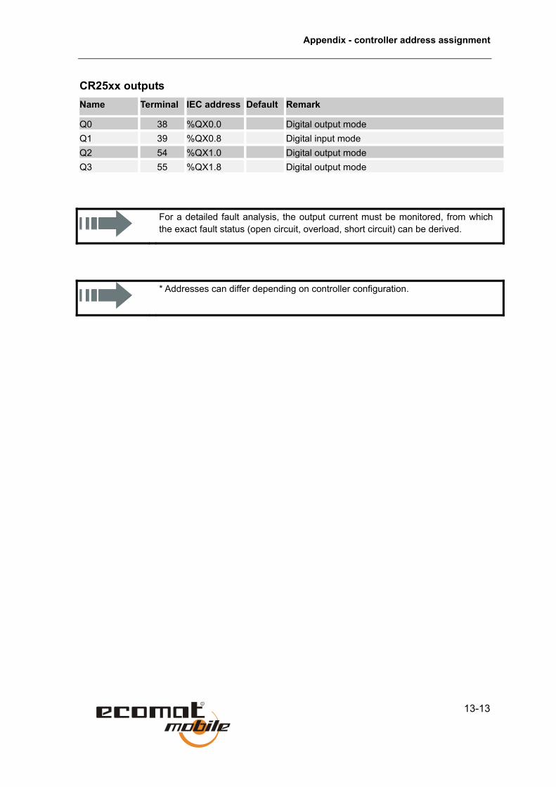
Appendix - controller address assignment
13-13
CR25xx outputs Name Terminal IEC address Default Remark
Q0 38 %QX0.0 Digital output mode Q1 39 %QX0.8 Digital input mode Q2 54 %QX1.0 Digital output mode Q3 55 %QX1.8 Digital output mode
For a detailed fault analysis, the output current must be monitored, from which the exact fault status (open circuit, overload, short circuit) can be derived.
* Addresses can differ depending on controller configuration.
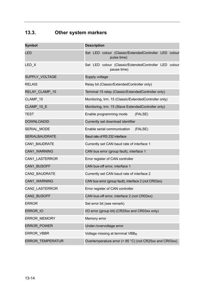
13-14
13.3. Other system markers Symbol Description
LED Set LED colour (Classic/ExtendedController LED colour pulse time)
LED_X Set LED colour (Classic/ExtendedController LED colour pause time)
SUPPLY_VOLTAGE Supply voltage
RELAIS Relay bit (Classic/ExtendedController only)
RELAY_CLAMP_15 Terminal 15 relay (Classic/ExtendedController only)
CLAMP_15 Monitoring, trm. 15 (Classic/ExtendedController only)
CLAMP_15_E Monitoring, trm. 15 (Slave ExtendedController only)
TEST Enable programming mode (FALSE)
DOWNLOADID Currently set download identifier
SERIAL_MODE Enable serial communication (FALSE)
SERIALBAUDRATE Baud rate of RS 232 interface
CAN1_BAUDRATE Currently set CAN baud rate of interface 1
CAN1_WARNING CAN bus error (group fault), interface 1
CAN1_LASTERROR Error register of CAN controller
CAN1_BUSOFF CAN bus-off error, interface 1
CAN2_BAUDRATE Currently set CAN baud rate of interface 2
CAN1_WARNING CAN bus error (group fault), interface 2 (not CR03xx)
CAN2_LASTERROR Error register of CAN controller
CAN2_BUSOFF CAN bus-off error, interface 2 (not CR03xx)
ERROR Set error bit (see remark)
ERROR_IO I/O error (group bit) (CR25xx and CR03xx only)
ERROR_MEMORY Memory error
ERROR_POWER Under-/overvoltage error
ERROR_VBBR Voltage missing at terminal VBBR
ERROR_TEMPERATUR Overtemperature error (> 85 °C) (not CR25xx and CR03xx)

Appendix - controller address assignment
13-15
Symbolic names with suffix E (for example ERROR_E) denote system addresses in the ExtendedController’s slave module. They have the same functions as the addresses in the master module.
Use only the symbolic names for programming, since the associated marker addresses can change when the control configuration is extended.
Special characteristics of the ERROR flag and the ERROR output
In controllers CR0020, CR0200 and CR0505, output ERROR (terminal 13) is set FALSE when system marker ERROR is set. Under no-fault conditions, the ERROR output is TRUE (negative logic).

13-16

14-1
14. Alphabetical index
A
Address assignment 13-1 Inputs 13-1 Outputs 13-8 System marker 13-14
Analog values, processing 11-37 INPUT_CURRENT 11-38 INPUT_VOLTAGE 11-37, 11-39
B
Boot-up routine 8-21 Bus level 8-5 Bus line length 8-6 Bus-off state 8-4
C
Cable cross-sections 8-6 CAN
Data exchange 8-2 General 8-1 Interfaces 8-1 Receiving data 8-2 System configuration 8-1 Transmitting data 8-2 Use of identifier 8-1
CAN errors 8-2 Bus-off state 8-4 Error count 8-3 Error messages 8-3 Error-active state 8-4 Error-passive state 8-4 Handling 8-2
CAN function blocks 8-9 CAN2 8-17 CANx_BAUDRATE 8-10 CANx_DOWNLOADID 8-11 CANx_ERRORHANDLER 8-15 CANx_RECEIVE 8-14 CANx_TRANSMIT 8-12
CAN, general information 8-8 Physical network configuration 8-8 Software for CAN and CANopen 8-8
CAN, physical connection 8-4 Bus level 8-5 Bus line length 8-6 Cable cross-sections 8-6 Network topology 8-4
CAN1_BUSOFF 6-1 CAN1_LASTERROR 6-1 CAN1_WARNING 6-1 CAN2 8-17 CAN2_BUSOFF 6-1 CAN2_LASTERROR 6-1 CAN2_WARNING 6-1 CANopen 8-18
Boot-up routine 8-21 Emergency Object 8-21 General information 8-18 Heartbeat object 8-21 Node-guarding object 8-21 Object directory 8-19 Process data objects (PDO) 8-20 Service data objects (SDO) 8-20
CANopen in CoDeSys 8-23 CANopen master 8-23, 8-25
CANopen master 8-23 CANx_SDO_READ 8-28 CANx_SDO_WRITE 8-29
CANopen slave 8-25 PDOs 8-26
CANx_BAUDRATE 8-10 CANx_DOWNLOADID 8-11 CANx_ERRORHANDLER 8-15 CANx_RECEIVE 8-14 CANx_SDO_READ 8-28 CANx_SDO_WRITE 8-29 CANx_TRANSMIT 8-12 CHECK_DATA 11-14 Control configuration 2-3 Control modes 5-4
Debug 5-4 Serial Mode 5-4 Test 5-4
Controlled systems 12-1 Controller functions 12-1
Controlled systems with compensation 12-1 Controlled systems with lag 12-2 Controlled systems without compensation
12-2 Damping overshoot 12-3 DELAY 12-4 GLR 12-16 PID 12-9 PID1 12-6

14-2
PT1 12-5 Setting method 12-3
Current measurement 9-5
D
Damping overshoot 12-3 Data - saving, reading and converting 11-2
Automatic data backups 11-2 E2READ_ 11-5 E2WRITE 11-4 FLASHREAD 11-7 FLASHWRITE 11-6 FRAMREAD 11-9 FRAMWRITE 11-8 Manual data backup 11-2 MEMCPY 11-3
Data access and verification 11-10 Data access and verification
CHECK_DATA 11-14 SET_IDENTITY 11-11 SET_PASSWORD 11-13
Debug 5-4 DELAY 12-4 Device configuration 4-1
Analog inputs 4-3 CabinetController 4-8 Classic and ExtendedController 4-4 Control modes of ExtendedController 4-11 Digital inputs 4-2 Digital outputs 4-1 Fast inputs 4-3 Function configuration 4-4 PWM outputs 4-1 SmartController 4-9 Software control configuration 4-13
Diagnostics signals 6-1
E
E2READ_ 11-5 E2WRITE 11-4 Emergency Object 8-21 Error 6-1
CAN1_BUSOFF 6-1 CAN1_LASTERROR 6-1 CAN1_WARNING 6-1 CAN2_BUSOFF 6-1 CAN2_LASTERROR 6-1 CAN2_WARNING 6-1 ERROR 6-1 ERROR_MEMORY 6-1
ERROR_POWER 6-1 ERROR_TEMPERATURE 6-1 ERROR_VBBR 6-1
ERROR 6-1 Error classes 6-1 Error codes 6-1 Error count 8-3 Error description 6-1 Error messages 8-3 ERROR_MEMORY 6-1 ERROR_POWER 6-1 ERROR_TEMPERATURE 6-1 ERROR_VBBR 6-1 Error-active state 8-4 Error-passive state 8-4
F
FAST_COUNT 10-11 Fatal Error 5-1 Feedback on outputs 3-3 FLASHREAD 11-7 FLASHWRITE 11-6 FRAMREAD 11-9 FRAMWRITE 11-8 FREQUENCY 10-2 Functions, ISO 11992 8-31 Functions, SAE J 1939 8-31
G
General notes about use of CAN 8-8 GLR 12-16
H
Heartbeat object 8-21 High-speed counters 10-1
FAST_COUNT 10-11 FREQUENCY 10-2 INC_ENCODER 10-9 PERIOD 10-3 PERIOD_RATIO 10-5 PHASE 10-7
I
INC_ENCODER 10-9 INPUT_CURRENT 11-38 INPUT_VOLTAGE 11-37, 11-39 Intended use 2-1 Interfaces, using 8-1 Interrupt processing 11-16
SET_INTERRUPT_I 11-20

Alphabetical index
14-3
SET_INTERRUPT_XMS 11-17 ISO 11992
ISO11992 8-44 ISO11992_GLOBAL_REQUEST 8-53 ISO11992_RECEIVE 8-45 ISO11992_RESPONSE 8-49 ISO11992_SPECIFIC_REQUEST 8-51 ISO11992_TRANSMIT 8-47
M
Manual data backup 11-2 MEMCPY 11-3 Monitoring system 3-1, 3-3
Block diagram 3-1 Clamp relay 3-1 Delayed shutdown 3-2 Function principle 3-3 Hardware setup 3-1 Terminal 15 engineering 3-1
N
Network topology 8-4 No operating system 5-1 Node-guarding object 8-21 NORM 11-35
O
Object directory 8-19 OCC_TASK 9-15 Operating states 5-1
Fatal Error 5-1 No operating system 5-1 Reset 5-1 Run 5-1 Status LED 5-2 Stop 5-1
Operating system 5-1, 5-2 Loading 5-2
Orientation aids Page footers 1-2 Page headers 1-2 Symbols 1-2
Other functions 11-1 SOFTRESET 11-1
OUTPUT_CURRENT 9-16 OUTPUT_CURRENT_CONTROL 9-13
P
P controller 12-14 PDOs 8-26
PERIOD 10-3 PERIOD_RATIO 10-5 PHASE 10-7 Physical connection to CAN 8-4 Physical layer according to ISO 11992-1 8-7 Physical network configuration 8-8 PI controller 12-12 PID 12-9 PID controller 12-7, 12-11 PID1 12-6 Process data objects (PDO) 8-20 PT1 12-5 PWM 9-1
Current measurement 9-5 Ramp function 9-6 Sample program 9-6
PWM channels 9-2 PWM dither 9-4, 9-5 PWM frequency 9-2 PWM function 9-1 PWM functions
OCC_TASK 9-14 OUTPUT_CURRENT 9-16 OUTPUT_CURRENT_CONTROL 9-11 PWM 9-7 PWM100 9-9
PWM/PWM 100 9-2
R
Ramp function 9-6 Receiving data 8-2 Required knowledge 1-1 Reset 5-1 Run 5-1
S
SAE J 1939 J1939_GLOBAL_REQUEST 8-42 J1939_RECEIVE 8-34, 8-35 J1939_RESPONSE 8-39 J1939_SPECIFIC_REQUEST 8-40 J1939_TRANSMIT 8-37
Safety instructions 2-1 Serial interface 11-27
SERIAL_BAUDRATE 11-27 SERIAL_PENDING 11-32 SERIAL_RX 11-30 SERIAL_TX 11-29
Serial Mode 5-4 SERIAL_BAUDRATE 11-27

14-4
SERIAL_PENDING 11-32 SERIAL_RX 11-30 SERIAL_TX 11-29 Service data objects (SDO) 8-20 SET_IDENTITY 11-11 SET_INTERRUPT_I 11-20 SET_INTERRUPT_XMS 11-17 SET_PASSWORD 11-13 SOFTRESET 11-1 Software for CAN and CANopen 8-8 SSC interface 11-22
SSC_MASTER 11-25 SSC_RECEIVE 11-22 SSC_TRANSMIT 11-24
SSC_MASTER 11-25 SSC_RECEIVE 11-22 SSC_TRANSMIT 11-24 Status LED 5-2 Stop 5-1 System configuration 8-1 System error 6-1
Response 6-1 System resources 7-1 System time 11-33
TIMER_READ 11-33 TIMER_US_READ 11-34
T
Terminal assignment 4-16 Labelling of input/output channels 4-16
Test 5-4 TIMER_READ 11-33 TIMER_US_READ 11-34 Transmitting data 8-2
U
Use of identifier 8-1
V
Variables, processing 11-35 NORM 11-35