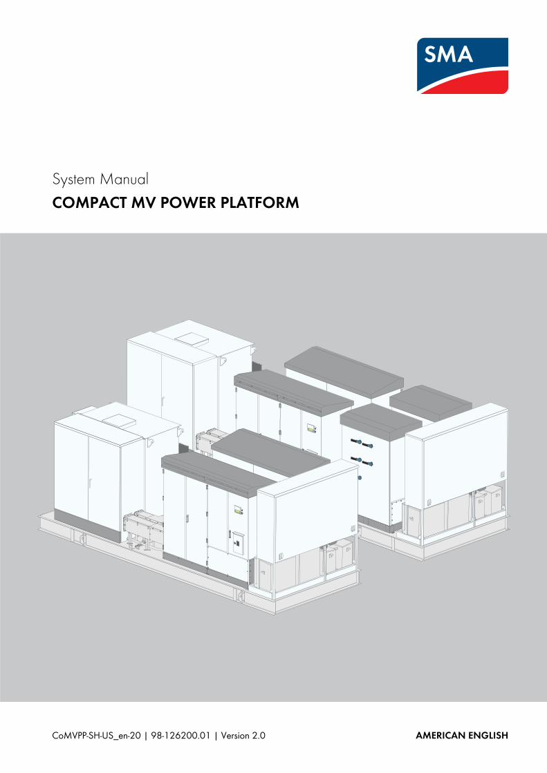
System Manual - COMPACT MV POWER PLATFORMfiles.sma.de/dl/20815/CoMVPP-SH-US_en-20w.pdf · SMA...
284
CoMVPP-SH-US_en-20 | 98-126200.01 | Version 2.0 AMERICAN ENGLISH System Manual COMPACT MV POWER PLATFORM
Transcript of System Manual - COMPACT MV POWER PLATFORMfiles.sma.de/dl/20815/CoMVPP-SH-US_en-20w.pdf · SMA...
CoMVPP-SH-US_en-20 | 98-126200.01 | Version 2.0 AMERICAN ENGLISH
System ManualCOMPACT MV POWER PLATFORM
Legal Provisions SMA America, LLC
2 CoMVPP-SH-US_en-20 System Manual
Legal ProvisionsCopyright © 2014 SMA America, LLC. All rights reserved.No part of this document may be reproduced, stored in a retrieval system, or transmitted, in any form or by any means, be it electronic, mechanical, photographic, magnetic or otherwise, without the prior written permission of SMA America, LLC.Neither SMA America, LLC nor SMA Solar Technology Canada Inc. makes representations, express or implied, with respect to this documentation or any of the equipment and/or software it may describe, including (with no limitation) any implied warranties of utility, merchantability, or fitness for any particular purpose. All such warranties are expressly disclaimed. Neither SMA America, LLC nor its distributors or dealers nor SMA Solar Technology Canada Inc. nor its distributors or dealers shall be liable for any indirect, incidental, or consequential damages under any circumstances.(The exclusion of implied warranties may not apply in all cases under some statutes, and thus the above exclusion may not apply.)Specifications are subject to change without notice. Every attempt has been made to make this document complete, accurate and up-to-date. Readers are cautioned, however, that SMA America, LLC and SMA Solar Technology Canada Inc. reserve the right to make changes without notice and shall not be responsible for any damages, including indirect, incidental or consequential damages, caused by reliance on the material presented, including, but not limited to, omissions, typographical errors, arithmetical errors or listing errors in the content material.TrademarksAll trademarks are recognized, even if not explicitly identified as such. A lack of identification does not mean that a product or symbol is not trademarked.The Bluetooth® word mark and logos are registered trademarks owned by Bluetooth SIG, Inc. and any use of these marks by SMA Solar Technology AG is under license.Modbus® is a registered trademark of Schneider Electric and is licensed by the Modbus Organization, Inc.QR Code® is a registered trademark of DENSO WAVE INCORPORATED.Phillips® and Pozidriv® are registered trademarks of Phillips Screw Company.Torx® is a registered trademark of Acument Global Technologies, Inc.
SMA America, LLC3801 N. Havana Street
Denver, CO 80239 U.S.A.
SMA Solar Technology Canada Inc.2425 Matheson Blvd. E
7th FloorMississauga, ON L4W 5K4
Canada
SMA America, LLC Important Safety Instructions
System Manual CoMVPP-SH-US_en-20 3
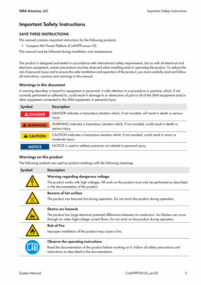
Important Safety InstructionsSAVE THESE INSTRUCTIONSThis manual contains important instructions for the following products:
• Compact MV Power Platform (CoMVPP-xxxxx-10)This manual must be followed during installation and maintenance.
The product is designed and tested in accordance with international safety requirements, but as with all electrical and electronic equipment, certain precautions must be observed when installing and/or operating the product. To reduce the risk of personal injury and to ensure the safe installation and operation of the product, you must carefully read and follow all instructions, cautions and warnings in this manual.
Warnings in this documentA warning describes a hazard to equipment or personnel. It calls attention to a procedure or practice, which, if not correctly performed or adhered to, could result in damage to or destruction of part or all of the SMA equipment and/or other equipment connected to the SMA equipment or personal injury.
Warnings on this productThe following symbols are used as product markings with the following meanings.
Symbol DescriptionDANGER indicates a hazardous situation which, if not avoided, will result in death or serious injury.WARNING indicates a hazardous situation which, if not avoided, could result in death or serious injury.CAUTION indicates a hazardous situation which, if not avoided, could result in minor or moderate injury.NOTICE is used to address practices not related to personal injury.
Symbol DescriptionWarning regarding dangerous voltageThe product works with high voltages. All work on the product must only be performed as described in the documentation of the product.Beware of hot surfaceThe product can become hot during operation. Do not touch the product during operation.
Electric arc hazardsThe product has large electrical potential differences between its conductors. Arc flashes can occur through air when high-voltage current flows. Do not work on the product during operation.Risk of FireImproper installation of the product may cause a fire.
Observe the operating instructionsRead the documentation of the product before working on it. Follow all safety precautions and instructions as described in the documentation.

General Warnings SMA America, LLC
4 CoMVPP-SH-US_en-20 System Manual
General Warnings
General WarningsAll electrical installations must be made in accordance with the local and National Electrical Code® ANSI/NFPA 70 or the Canadian Electrical Code® CSA C22.1. This document does not and is not intended to replace any local, state, provincial, federal or national laws, regulation or codes applicable to the installation and use of the product, including without limitation applicable electrical safety codes. All installations must conform with the laws, regulations, codes and standards applicable in the jurisdiction of installation. SMA assumes no responsibility for the compliance or noncompliance with such laws or codes in connection with the installation of the product.Before installing or using the product, read all of the instructions, cautions, and warnings in this manual.Before connecting the product to the electrical utility grid, contact the local utility company. This connection must be made only by qualified personnel.Wiring of the product must be made by qualified personnel only.

SMA America, LLC Table of Contents
System Manual CoMVPP-SH-US_en-20 1
Table of Contents1 Information on this Document. . . . . . . . . . . . . . . . . . . . . . . . . . . . . . . . . . . . . . . . . . . . . . . . . . . . 12
1.1 Validity . . . . . . . . . . . . . . . . . . . . . . . . . . . . . . . . . . . . . . . . . . . . . . . . . . . . . . . . . . . . . . . . . . . . . . . . . . . . . 121.2 Content and Structure of the Document . . . . . . . . . . . . . . . . . . . . . . . . . . . . . . . . . . . . . . . . . . . . . . . . . . . . 121.3 Target Group . . . . . . . . . . . . . . . . . . . . . . . . . . . . . . . . . . . . . . . . . . . . . . . . . . . . . . . . . . . . . . . . . . . . . . . . 131.4 Additional Information . . . . . . . . . . . . . . . . . . . . . . . . . . . . . . . . . . . . . . . . . . . . . . . . . . . . . . . . . . . . . . . . . 131.5 Symbols . . . . . . . . . . . . . . . . . . . . . . . . . . . . . . . . . . . . . . . . . . . . . . . . . . . . . . . . . . . . . . . . . . . . . . . . . . . . 131.6 Typographies . . . . . . . . . . . . . . . . . . . . . . . . . . . . . . . . . . . . . . . . . . . . . . . . . . . . . . . . . . . . . . . . . . . . . . . . 131.7 Nomenclature. . . . . . . . . . . . . . . . . . . . . . . . . . . . . . . . . . . . . . . . . . . . . . . . . . . . . . . . . . . . . . . . . . . . . . . . 141.8 Abbreviations . . . . . . . . . . . . . . . . . . . . . . . . . . . . . . . . . . . . . . . . . . . . . . . . . . . . . . . . . . . . . . . . . . . . . . . . 14
2 Safety . . . . . . . . . . . . . . . . . . . . . . . . . . . . . . . . . . . . . . . . . . . . . . . . . . . . . . . . . . . . . . . . . . . . . . . 152.1 Intended Use . . . . . . . . . . . . . . . . . . . . . . . . . . . . . . . . . . . . . . . . . . . . . . . . . . . . . . . . . . . . . . . . . . . . . . . . 152.2 Safety Precautions . . . . . . . . . . . . . . . . . . . . . . . . . . . . . . . . . . . . . . . . . . . . . . . . . . . . . . . . . . . . . . . . . . . . 162.3 Personal Protective Equipment . . . . . . . . . . . . . . . . . . . . . . . . . . . . . . . . . . . . . . . . . . . . . . . . . . . . . . . . . . . 19
3 Transport and Mounting . . . . . . . . . . . . . . . . . . . . . . . . . . . . . . . . . . . . . . . . . . . . . . . . . . . . . . . . 203.1 Safety Precautions for Transport and Mounting . . . . . . . . . . . . . . . . . . . . . . . . . . . . . . . . . . . . . . . . . . . . . . 203.2 Requirement for Transport and Mounting. . . . . . . . . . . . . . . . . . . . . . . . . . . . . . . . . . . . . . . . . . . . . . . . . . . 20
3.2.1 Ambient Conditions . . . . . . . . . . . . . . . . . . . . . . . . . . . . . . . . . . . . . . . . . . . . . . . . . . . . . . . . . . . . . . . . . . . . . .203.2.2 Requirements for Transport by Truck . . . . . . . . . . . . . . . . . . . . . . . . . . . . . . . . . . . . . . . . . . . . . . . . . . . . . . . . .213.2.3 Center of Gravity . . . . . . . . . . . . . . . . . . . . . . . . . . . . . . . . . . . . . . . . . . . . . . . . . . . . . . . . . . . . . . . . . . . . . . . .21
3.3 Transporting the MV Power Platform by Crane . . . . . . . . . . . . . . . . . . . . . . . . . . . . . . . . . . . . . . . . . . . . . . 213.4 Transporting the MV Power Platform by Truck . . . . . . . . . . . . . . . . . . . . . . . . . . . . . . . . . . . . . . . . . . . . . . . 23
3.4.1 Securing the MV Power Platform for Transport by Truck . . . . . . . . . . . . . . . . . . . . . . . . . . . . . . . . . . . . . . . . . .233.4.2 Preparing the MV Power Platform for Unloading from Truck. . . . . . . . . . . . . . . . . . . . . . . . . . . . . . . . . . . . . . .24
3.4.2.1 Removing the Base Plates from the MV Power Platform . . . . . . . . . . . . . . . . . . . . . . . . . . . . . . . . . . . . . . . . . . . .243.4.2.2 Removing the Lashing Chains and Tie-Down Straps . . . . . . . . . . . . . . . . . . . . . . . . . . . . . . . . . . . . . . . . . . . . . . .26
3.5 Mounting the MV Power Platform . . . . . . . . . . . . . . . . . . . . . . . . . . . . . . . . . . . . . . . . . . . . . . . . . . . . . . . . 263.5.1 Transporting the MV Power Platform to the Support Surface . . . . . . . . . . . . . . . . . . . . . . . . . . . . . . . . . . . . . .273.5.2 Fastening the MV Power Platform using Anchor Clips . . . . . . . . . . . . . . . . . . . . . . . . . . . . . . . . . . . . . . . . . . . .27
4 Installation . . . . . . . . . . . . . . . . . . . . . . . . . . . . . . . . . . . . . . . . . . . . . . . . . . . . . . . . . . . . . . . . . . . 294.1 Safety during Installation . . . . . . . . . . . . . . . . . . . . . . . . . . . . . . . . . . . . . . . . . . . . . . . . . . . . . . . . . . . . . . . 294.2 Sequence of Installation Work . . . . . . . . . . . . . . . . . . . . . . . . . . . . . . . . . . . . . . . . . . . . . . . . . . . . . . . . . . . 324.3 Preparatory Work. . . . . . . . . . . . . . . . . . . . . . . . . . . . . . . . . . . . . . . . . . . . . . . . . . . . . . . . . . . . . . . . . . . . . 32
4.3.1 Removing the Transport Locks . . . . . . . . . . . . . . . . . . . . . . . . . . . . . . . . . . . . . . . . . . . . . . . . . . . . . . . . . . . . . .324.3.2 Preparing the Cable Entry . . . . . . . . . . . . . . . . . . . . . . . . . . . . . . . . . . . . . . . . . . . . . . . . . . . . . . . . . . . . . . . . .32
4.3.2.1 Position of the Base Plates. . . . . . . . . . . . . . . . . . . . . . . . . . . . . . . . . . . . . . . . . . . . . . . . . . . . . . . . . . . . . . . . . . .334.3.2.2 Cable Entry into the Disconnect Unit. . . . . . . . . . . . . . . . . . . . . . . . . . . . . . . . . . . . . . . . . . . . . . . . . . . . . . . . . . .344.3.2.3 Cable Entry into Sunny Central Inverters . . . . . . . . . . . . . . . . . . . . . . . . . . . . . . . . . . . . . . . . . . . . . . . . . . . . . . .344.3.2.4 Cable Entry into the MV Transformer . . . . . . . . . . . . . . . . . . . . . . . . . . . . . . . . . . . . . . . . . . . . . . . . . . . . . . . . . .344.3.2.5 Cable Entry into the Auxiliary Services Rack. . . . . . . . . . . . . . . . . . . . . . . . . . . . . . . . . . . . . . . . . . . . . . . . . . . . .344.3.2.6 Punching the Holes in the Base Plates. . . . . . . . . . . . . . . . . . . . . . . . . . . . . . . . . . . . . . . . . . . . . . . . . . . . . . . . . .35
4.4 Installing the Grounding Cable in the Base Platform . . . . . . . . . . . . . . . . . . . . . . . . . . . . . . . . . . . . . . . . . . 354.4.1 Connection Overview . . . . . . . . . . . . . . . . . . . . . . . . . . . . . . . . . . . . . . . . . . . . . . . . . . . . . . . . . . . . . . . . . . . .354.4.2 Cable Requirements for Grounding. . . . . . . . . . . . . . . . . . . . . . . . . . . . . . . . . . . . . . . . . . . . . . . . . . . . . . . . . .364.4.3 Connecting the Grounding Pads . . . . . . . . . . . . . . . . . . . . . . . . . . . . . . . . . . . . . . . . . . . . . . . . . . . . . . . . . . . .37
Table of Contents SMA America, LLC
2 CoMVPP-SH-US_en-20 System Manual
4.5 Installing the Grounding Cable in the Disconnect Unit . . . . . . . . . . . . . . . . . . . . . . . . . . . . . . . . . . . . . . . . 384.5.1 Overview of the Connection Area. . . . . . . . . . . . . . . . . . . . . . . . . . . . . . . . . . . . . . . . . . . . . . . . . . . . . . . . . . .384.5.2 Cable Requirements for Cables and Terminal Lugs . . . . . . . . . . . . . . . . . . . . . . . . . . . . . . . . . . . . . . . . . . . . . .384.5.3 Connecting the Grounding Cables in Disconnect Unit . . . . . . . . . . . . . . . . . . . . . . . . . . . . . . . . . . . . . . . . . . .38
4.6 Connecting Grounding Cables in Sunny Central. . . . . . . . . . . . . . . . . . . . . . . . . . . . . . . . . . . . . . . . . . . . . 394.7 Installing the AC Connection in the MV Transformer . . . . . . . . . . . . . . . . . . . . . . . . . . . . . . . . . . . . . . . . . . 40
4.7.1 Safety during AC Connection . . . . . . . . . . . . . . . . . . . . . . . . . . . . . . . . . . . . . . . . . . . . . . . . . . . . . . . . . . . . . .404.7.1.1 Overview of the Connection Area. . . . . . . . . . . . . . . . . . . . . . . . . . . . . . . . . . . . . . . . . . . . . . . . . . . . . . . . . . . . 404.7.1.2 Position of the Deadbreak Bushings . . . . . . . . . . . . . . . . . . . . . . . . . . . . . . . . . . . . . . . . . . . . . . . . . . . . . . . . . . 414.7.1.3 Circuit Diagram . . . . . . . . . . . . . . . . . . . . . . . . . . . . . . . . . . . . . . . . . . . . . . . . . . . . . . . . . . . . . . . . . . . . . . . . . . 414.7.1.4 Connecting the AC Cables . . . . . . . . . . . . . . . . . . . . . . . . . . . . . . . . . . . . . . . . . . . . . . . . . . . . . . . . . . . . . . . . . 42
4.8 Checking the Cable Connection for Supply Voltage, Communication and Control Systems. . . . . . . . . . . . 424.8.1 Overview of the Auxiliary Services Rack . . . . . . . . . . . . . . . . . . . . . . . . . . . . . . . . . . . . . . . . . . . . . . . . . . . . . .424.8.2 Installation Sequence. . . . . . . . . . . . . . . . . . . . . . . . . . . . . . . . . . . . . . . . . . . . . . . . . . . . . . . . . . . . . . . . . . . . .434.8.3 Connecting the External Supply Voltage in the Brown Power Box . . . . . . . . . . . . . . . . . . . . . . . . . . . . . . . . . .44
4.8.3.1 Overview of the Connection Area. . . . . . . . . . . . . . . . . . . . . . . . . . . . . . . . . . . . . . . . . . . . . . . . . . . . . . . . . . . . 444.8.3.2 Cable Requirements . . . . . . . . . . . . . . . . . . . . . . . . . . . . . . . . . . . . . . . . . . . . . . . . . . . . . . . . . . . . . . . . . . . . . . 444.8.3.3 Inserting and Connecting the Cables . . . . . . . . . . . . . . . . . . . . . . . . . . . . . . . . . . . . . . . . . . . . . . . . . . . . . . . . . 45
4.8.4 Connecting the Communication in the Main Box . . . . . . . . . . . . . . . . . . . . . . . . . . . . . . . . . . . . . . . . . . . . . . .454.8.4.1 Structure of the Communication Network . . . . . . . . . . . . . . . . . . . . . . . . . . . . . . . . . . . . . . . . . . . . . . . . . . . . . . 454.8.4.2 Overview of the Connection Area. . . . . . . . . . . . . . . . . . . . . . . . . . . . . . . . . . . . . . . . . . . . . . . . . . . . . . . . . . . . 464.8.4.3 Connecting the Communication in the Main Box Using Optical Fibers. . . . . . . . . . . . . . . . . . . . . . . . . . . . . . . . 47
4.8.5 Connecting Analog Setpoints in the Main Box . . . . . . . . . . . . . . . . . . . . . . . . . . . . . . . . . . . . . . . . . . . . . . . . .484.8.5.1 Overview of the Connection Area. . . . . . . . . . . . . . . . . . . . . . . . . . . . . . . . . . . . . . . . . . . . . . . . . . . . . . . . . . . . 484.8.5.2 Cable Requirements . . . . . . . . . . . . . . . . . . . . . . . . . . . . . . . . . . . . . . . . . . . . . . . . . . . . . . . . . . . . . . . . . . . . . . 494.8.5.3 Inserting and Connecting the Cables . . . . . . . . . . . . . . . . . . . . . . . . . . . . . . . . . . . . . . . . . . . . . . . . . . . . . . . . . 49
4.8.6 Connecting the External Fast Stop in the Main Box. . . . . . . . . . . . . . . . . . . . . . . . . . . . . . . . . . . . . . . . . . . . . .494.8.6.1 Overview of the Connection Area. . . . . . . . . . . . . . . . . . . . . . . . . . . . . . . . . . . . . . . . . . . . . . . . . . . . . . . . . . . . 494.8.6.2 Cable Requirements . . . . . . . . . . . . . . . . . . . . . . . . . . . . . . . . . . . . . . . . . . . . . . . . . . . . . . . . . . . . . . . . . . . . . . 504.8.6.3 Inserting and Connecting the Cables . . . . . . . . . . . . . . . . . . . . . . . . . . . . . . . . . . . . . . . . . . . . . . . . . . . . . . . . . 50
4.8.7 Connecting the Remote Shutdown in the Main Box . . . . . . . . . . . . . . . . . . . . . . . . . . . . . . . . . . . . . . . . . . . . .514.8.7.1 Overview of the Connection Area. . . . . . . . . . . . . . . . . . . . . . . . . . . . . . . . . . . . . . . . . . . . . . . . . . . . . . . . . . . . 514.8.7.2 Cable Requirements . . . . . . . . . . . . . . . . . . . . . . . . . . . . . . . . . . . . . . . . . . . . . . . . . . . . . . . . . . . . . . . . . . . . . . 514.8.7.3 Inserting and Connecting the Cables . . . . . . . . . . . . . . . . . . . . . . . . . . . . . . . . . . . . . . . . . . . . . . . . . . . . . . . . . 51
4.8.8 Connecting the Insulation Monitoring in the Main Box . . . . . . . . . . . . . . . . . . . . . . . . . . . . . . . . . . . . . . . . . . .524.8.8.1 Overview of the Connection Area. . . . . . . . . . . . . . . . . . . . . . . . . . . . . . . . . . . . . . . . . . . . . . . . . . . . . . . . . . . . 524.8.8.2 Cable Requirements . . . . . . . . . . . . . . . . . . . . . . . . . . . . . . . . . . . . . . . . . . . . . . . . . . . . . . . . . . . . . . . . . . . . . . 524.8.8.3 Inserting and Connecting the Cables . . . . . . . . . . . . . . . . . . . . . . . . . . . . . . . . . . . . . . . . . . . . . . . . . . . . . . . . . 53
4.8.9 Connecting the Tracker Motors in the Tracker Box . . . . . . . . . . . . . . . . . . . . . . . . . . . . . . . . . . . . . . . . . . . . . .534.8.9.1 Overview of the Connection Area. . . . . . . . . . . . . . . . . . . . . . . . . . . . . . . . . . . . . . . . . . . . . . . . . . . . . . . . . . . . 534.8.9.2 Cable Requirements . . . . . . . . . . . . . . . . . . . . . . . . . . . . . . . . . . . . . . . . . . . . . . . . . . . . . . . . . . . . . . . . . . . . . . 544.8.9.3 Inserting and Connecting the Cables . . . . . . . . . . . . . . . . . . . . . . . . . . . . . . . . . . . . . . . . . . . . . . . . . . . . . . . . . 54
4.8.10 Connecting a Customer-Specific Box. . . . . . . . . . . . . . . . . . . . . . . . . . . . . . . . . . . . . . . . . . . . . . . . . . . . . . . . .544.8.10.1 Overview of the Connection Area. . . . . . . . . . . . . . . . . . . . . . . . . . . . . . . . . . . . . . . . . . . . . . . . . . . . . . . . . . . . 544.8.10.2 Inserting and Connecting the Cables . . . . . . . . . . . . . . . . . . . . . . . . . . . . . . . . . . . . . . . . . . . . . . . . . . . . . . . . . 55
4.9 Installing the DC Connection . . . . . . . . . . . . . . . . . . . . . . . . . . . . . . . . . . . . . . . . . . . . . . . . . . . . . . . . . . . . 564.9.1 Safety during DC Connection . . . . . . . . . . . . . . . . . . . . . . . . . . . . . . . . . . . . . . . . . . . . . . . . . . . . . . . . . . . . . .564.9.2 Cable Requirements. . . . . . . . . . . . . . . . . . . . . . . . . . . . . . . . . . . . . . . . . . . . . . . . . . . . . . . . . . . . . . . . . . . . . .574.9.3 Connecting the DC Cables in the Disconnect Units . . . . . . . . . . . . . . . . . . . . . . . . . . . . . . . . . . . . . . . . . . . . . .58
SMA America, LLC Table of Contents
System Manual CoMVPP-SH-US_en-20 3
4.9.3.1 Overview of the Connection Area . . . . . . . . . . . . . . . . . . . . . . . . . . . . . . . . . . . . . . . . . . . . . . . . . . . . . . . . . . . .584.9.3.2 Connecting the DC Cables in Disconnect Unit 1 . . . . . . . . . . . . . . . . . . . . . . . . . . . . . . . . . . . . . . . . . . . . . . . . .594.9.3.3 Connecting the DC Cables in Disconnect Unit 2 . . . . . . . . . . . . . . . . . . . . . . . . . . . . . . . . . . . . . . . . . . . . . . . . .59
4.9.4 Connecting the DC Cables to the Sunny Central. . . . . . . . . . . . . . . . . . . . . . . . . . . . . . . . . . . . . . . . . . . . . . . .604.10 Final Installation Work . . . . . . . . . . . . . . . . . . . . . . . . . . . . . . . . . . . . . . . . . . . . . . . . . . . . . . . . . . . . . . . . . 61
4.10.1 Sealing the Base Plates . . . . . . . . . . . . . . . . . . . . . . . . . . . . . . . . . . . . . . . . . . . . . . . . . . . . . . . . . . . . . . . . . . .614.10.2 Mounting the Panels . . . . . . . . . . . . . . . . . . . . . . . . . . . . . . . . . . . . . . . . . . . . . . . . . . . . . . . . . . . . . . . . . . . . .61
5 Disconnecting and Reconnecting . . . . . . . . . . . . . . . . . . . . . . . . . . . . . . . . . . . . . . . . . . . . . . . . . 625.1 Safety When Disconnecting and Reconnecting . . . . . . . . . . . . . . . . . . . . . . . . . . . . . . . . . . . . . . . . . . . . . . 625.2 System and Equipment Disconnecting Means . . . . . . . . . . . . . . . . . . . . . . . . . . . . . . . . . . . . . . . . . . . . . . . 63
5.2.1 Overview of System Disconnecting Means - Power Circuit . . . . . . . . . . . . . . . . . . . . . . . . . . . . . . . . . . . . . . . .635.2.2 Overview of System Disconnecting Means - Supply Voltage . . . . . . . . . . . . . . . . . . . . . . . . . . . . . . . . . . . . . .63
5.2.2.1 Internal Supply Voltage . . . . . . . . . . . . . . . . . . . . . . . . . . . . . . . . . . . . . . . . . . . . . . . . . . . . . . . . . . . . . . . . . . . .645.2.2.2 External Supply Voltage . . . . . . . . . . . . . . . . . . . . . . . . . . . . . . . . . . . . . . . . . . . . . . . . . . . . . . . . . . . . . . . . . . . .64
5.3 Disconnecting the Compact MV Power Platform . . . . . . . . . . . . . . . . . . . . . . . . . . . . . . . . . . . . . . . . . . . . . 655.3.1 Switching off the Inverters . . . . . . . . . . . . . . . . . . . . . . . . . . . . . . . . . . . . . . . . . . . . . . . . . . . . . . . . . . . . . . . . .655.3.2 Disconnecting the DC Side . . . . . . . . . . . . . . . . . . . . . . . . . . . . . . . . . . . . . . . . . . . . . . . . . . . . . . . . . . . . . . . .65
5.3.2.1 For Platforms with External DC Disconnects . . . . . . . . . . . . . . . . . . . . . . . . . . . . . . . . . . . . . . . . . . . . . . . . . . . . .655.3.2.2 For Platforms with Internal DC Switch . . . . . . . . . . . . . . . . . . . . . . . . . . . . . . . . . . . . . . . . . . . . . . . . . . . . . . . . . .66
5.3.3 Disconnecting the AC Side . . . . . . . . . . . . . . . . . . . . . . . . . . . . . . . . . . . . . . . . . . . . . . . . . . . . . . . . . . . . . . . .675.3.4 Disconnecting the Supply Voltage Source. . . . . . . . . . . . . . . . . . . . . . . . . . . . . . . . . . . . . . . . . . . . . . . . . . . . .69
5.3.4.1 For Platforms Configured for Internal Supply . . . . . . . . . . . . . . . . . . . . . . . . . . . . . . . . . . . . . . . . . . . . . . . . . . . .695.3.4.2 For Platforms Configured for External Supply . . . . . . . . . . . . . . . . . . . . . . . . . . . . . . . . . . . . . . . . . . . . . . . . . . . .71
5.4 Reconnecting the MV Power Platform. . . . . . . . . . . . . . . . . . . . . . . . . . . . . . . . . . . . . . . . . . . . . . . . . . . . . . 725.4.1 Reconnecting the Supply Voltage Source . . . . . . . . . . . . . . . . . . . . . . . . . . . . . . . . . . . . . . . . . . . . . . . . . . . . .72
5.4.1.1 For Platforms Configured for Internal Supply . . . . . . . . . . . . . . . . . . . . . . . . . . . . . . . . . . . . . . . . . . . . . . . . . . . .725.4.1.2 For Platforms Configured for External Supply . . . . . . . . . . . . . . . . . . . . . . . . . . . . . . . . . . . . . . . . . . . . . . . . . . . .72
5.4.2 Reconnecting the AC Source . . . . . . . . . . . . . . . . . . . . . . . . . . . . . . . . . . . . . . . . . . . . . . . . . . . . . . . . . . . . . . .735.4.3 Reconnecting the DC Sources . . . . . . . . . . . . . . . . . . . . . . . . . . . . . . . . . . . . . . . . . . . . . . . . . . . . . . . . . . . . . .74
5.4.3.1 For Platforms with External DC Disconnects . . . . . . . . . . . . . . . . . . . . . . . . . . . . . . . . . . . . . . . . . . . . . . . . . . . . .745.4.3.2 For Platforms with Internal DC Switches . . . . . . . . . . . . . . . . . . . . . . . . . . . . . . . . . . . . . . . . . . . . . . . . . . . . . . . .74
5.4.4 Restarting the Inverters. . . . . . . . . . . . . . . . . . . . . . . . . . . . . . . . . . . . . . . . . . . . . . . . . . . . . . . . . . . . . . . . . . . .745.5 System Disconnection . . . . . . . . . . . . . . . . . . . . . . . . . . . . . . . . . . . . . . . . . . . . . . . . . . . . . . . . . . . . . . . . . . 74
5.5.1 Disconnecting the Inverter . . . . . . . . . . . . . . . . . . . . . . . . . . . . . . . . . . . . . . . . . . . . . . . . . . . . . . . . . . . . . . . . .745.5.2 Disconnecting Both Inverters . . . . . . . . . . . . . . . . . . . . . . . . . . . . . . . . . . . . . . . . . . . . . . . . . . . . . . . . . . . . . . .765.5.3 Disconnecting the Medium-Voltage Transformer . . . . . . . . . . . . . . . . . . . . . . . . . . . . . . . . . . . . . . . . . . . . . . . .775.5.4 Disconnecting the Tracker Motor Circuits . . . . . . . . . . . . . . . . . . . . . . . . . . . . . . . . . . . . . . . . . . . . . . . . . . . . .775.5.5 Disconnecting the 120V Auxiliary Circuits of the Platform. . . . . . . . . . . . . . . . . . . . . . . . . . . . . . . . . . . . . . . . .78
6 Operation . . . . . . . . . . . . . . . . . . . . . . . . . . . . . . . . . . . . . . . . . . . . . . . . . . . . . . . . . . . . . . . . . . . . 796.1 System Settings via Touch Display . . . . . . . . . . . . . . . . . . . . . . . . . . . . . . . . . . . . . . . . . . . . . . . . . . . . . . . . 79
6.1.1 Selecting the Language . . . . . . . . . . . . . . . . . . . . . . . . . . . . . . . . . . . . . . . . . . . . . . . . . . . . . . . . . . . . . . . . . . .796.1.2 Setting the Date, Time and Time Zone . . . . . . . . . . . . . . . . . . . . . . . . . . . . . . . . . . . . . . . . . . . . . . . . . . . . . . . .796.1.3 Selecting the Display Format of the Touch Display . . . . . . . . . . . . . . . . . . . . . . . . . . . . . . . . . . . . . . . . . . . . . .796.1.4 Setting the Brightness of the Touch Display . . . . . . . . . . . . . . . . . . . . . . . . . . . . . . . . . . . . . . . . . . . . . . . . . . . .79
6.2 Changing the System Settings via the User Interface . . . . . . . . . . . . . . . . . . . . . . . . . . . . . . . . . . . . . . . . . . 806.2.1 Setting the Language . . . . . . . . . . . . . . . . . . . . . . . . . . . . . . . . . . . . . . . . . . . . . . . . . . . . . . . . . . . . . . . . . . . . .806.2.2 Setting the Date, Time and Time Zone . . . . . . . . . . . . . . . . . . . . . . . . . . . . . . . . . . . . . . . . . . . . . . . . . . . . . . . .80

SMA America, LLC
4 CoMVPP-SH-US_en-20 System Manual
6.2.3 Entering the Operator Name. . . . . . . . . . . . . . . . . . . . . . . . . . . . . . . . . . . . . . . . . . . . . . . . . . . . . . . . . . . . . . .806.2.4 Resetting the SC-COM . . . . . . . . . . . . . . . . . . . . . . . . . . . . . . . . . . . . . . . . . . . . . . . . . . . . . . . . . . . . . . . . . . .816.2.5 Changing the Password for the User Groups . . . . . . . . . . . . . . . . . . . . . . . . . . . . . . . . . . . . . . . . . . . . . . . . . .816.2.6 Customized Settings via XML File . . . . . . . . . . . . . . . . . . . . . . . . . . . . . . . . . . . . . . . . . . . . . . . . . . . . . . . . . . .81
6.2.6.1 Uploading the custom.xml File. . . . . . . . . . . . . . . . . . . . . . . . . . . . . . . . . . . . . . . . . . . . . . . . . . . . . . . . . . . . . . . 826.2.6.2 Downloading the XML File custom.xml . . . . . . . . . . . . . . . . . . . . . . . . . . . . . . . . . . . . . . . . . . . . . . . . . . . . . . . . 826.2.6.3 Deleting the custom.xml File . . . . . . . . . . . . . . . . . . . . . . . . . . . . . . . . . . . . . . . . . . . . . . . . . . . . . . . . . . . . . . . . 83
6.2.7 XML File for Customer-Specific Settings . . . . . . . . . . . . . . . . . . . . . . . . . . . . . . . . . . . . . . . . . . . . . . . . . . . . . . .836.2.7.1 Structure of the XML File custom.xml . . . . . . . . . . . . . . . . . . . . . . . . . . . . . . . . . . . . . . . . . . . . . . . . . . . . . . . . . . 836.2.7.2 Parameters and Values for the custom.xml File . . . . . . . . . . . . . . . . . . . . . . . . . . . . . . . . . . . . . . . . . . . . . . . . . . 84
6.2.8 Communication with Sunny Portal . . . . . . . . . . . . . . . . . . . . . . . . . . . . . . . . . . . . . . . . . . . . . . . . . . . . . . . . . . .856.2.8.1 Information on Communication with Sunny Portal . . . . . . . . . . . . . . . . . . . . . . . . . . . . . . . . . . . . . . . . . . . . . . . . 856.2.8.2 Accessing the SC-COM via Sunny Portal . . . . . . . . . . . . . . . . . . . . . . . . . . . . . . . . . . . . . . . . . . . . . . . . . . . . . . 86
6.2.9 User Rights and Data Security . . . . . . . . . . . . . . . . . . . . . . . . . . . . . . . . . . . . . . . . . . . . . . . . . . . . . . . . . . . . . .866.2.9.1 User Groups . . . . . . . . . . . . . . . . . . . . . . . . . . . . . . . . . . . . . . . . . . . . . . . . . . . . . . . . . . . . . . . . . . . . . . . . . . . . 866.2.9.2 Strength of Passwords . . . . . . . . . . . . . . . . . . . . . . . . . . . . . . . . . . . . . . . . . . . . . . . . . . . . . . . . . . . . . . . . . . . . . 876.2.9.3 Increasing Data Security . . . . . . . . . . . . . . . . . . . . . . . . . . . . . . . . . . . . . . . . . . . . . . . . . . . . . . . . . . . . . . . . . . . 87
6.3 Network Settings . . . . . . . . . . . . . . . . . . . . . . . . . . . . . . . . . . . . . . . . . . . . . . . . . . . . . . . . . . . . . . . . . . . . . 876.3.1 Configuring the Network Settings on the Computer . . . . . . . . . . . . . . . . . . . . . . . . . . . . . . . . . . . . . . . . . . . . .876.3.2 Configuring the Inverter for the Local Network . . . . . . . . . . . . . . . . . . . . . . . . . . . . . . . . . . . . . . . . . . . . . . . . .88
6.3.2.1 Information on Integrating the Inverter into a Local Network . . . . . . . . . . . . . . . . . . . . . . . . . . . . . . . . . . . . . . . 886.3.2.2 Configuring the Inverter for Static Networks . . . . . . . . . . . . . . . . . . . . . . . . . . . . . . . . . . . . . . . . . . . . . . . . . . . . 886.3.2.3 Configuring Inverters for Dynamic Networks. . . . . . . . . . . . . . . . . . . . . . . . . . . . . . . . . . . . . . . . . . . . . . . . . . . . 896.3.2.4 Adjusting Network Ports . . . . . . . . . . . . . . . . . . . . . . . . . . . . . . . . . . . . . . . . . . . . . . . . . . . . . . . . . . . . . . . . . . . 89
6.4 Displaying Operating Data . . . . . . . . . . . . . . . . . . . . . . . . . . . . . . . . . . . . . . . . . . . . . . . . . . . . . . . . . . . . . 906.4.1 Displaying the Operating Data on the Touch Display . . . . . . . . . . . . . . . . . . . . . . . . . . . . . . . . . . . . . . . . . . . .906.4.2 Displaying the Operating Data via the User Interface. . . . . . . . . . . . . . . . . . . . . . . . . . . . . . . . . . . . . . . . . . . .906.4.3 Displaying the Operation Data via Sunny Portal. . . . . . . . . . . . . . . . . . . . . . . . . . . . . . . . . . . . . . . . . . . . . . . .90
6.4.3.1 Registering the Inverter in Sunny Portal . . . . . . . . . . . . . . . . . . . . . . . . . . . . . . . . . . . . . . . . . . . . . . . . . . . . . . . . 906.4.3.2 Adjusting the PV System Identifier for Sunny Portal . . . . . . . . . . . . . . . . . . . . . . . . . . . . . . . . . . . . . . . . . . . . . . . 916.4.3.3 Deleting the Sunny Portal Buffer . . . . . . . . . . . . . . . . . . . . . . . . . . . . . . . . . . . . . . . . . . . . . . . . . . . . . . . . . . . . . 91
6.4.4 Displaying the Event Report . . . . . . . . . . . . . . . . . . . . . . . . . . . . . . . . . . . . . . . . . . . . . . . . . . . . . . . . . . . . . . . .916.5 Saving the Operating Data . . . . . . . . . . . . . . . . . . . . . . . . . . . . . . . . . . . . . . . . . . . . . . . . . . . . . . . . . . . . . 92
6.5.1 Increasing Storage Capacity by Averaging . . . . . . . . . . . . . . . . . . . . . . . . . . . . . . . . . . . . . . . . . . . . . . . . . . .926.5.2 Setting the Data Transmission Frequency . . . . . . . . . . . . . . . . . . . . . . . . . . . . . . . . . . . . . . . . . . . . . . . . . . . . .926.5.3 Downloading Operating Data Using the FTP Server . . . . . . . . . . . . . . . . . . . . . . . . . . . . . . . . . . . . . . . . . . . . .93
6.5.3.1 Defining Read and Write Access Rights for the FTP Server . . . . . . . . . . . . . . . . . . . . . . . . . . . . . . . . . . . . . . . . . 936.5.3.2 Accessing the FTP Server via the Internet Browser. . . . . . . . . . . . . . . . . . . . . . . . . . . . . . . . . . . . . . . . . . . . . . . . 936.5.3.3 Sending Data via FTP Push . . . . . . . . . . . . . . . . . . . . . . . . . . . . . . . . . . . . . . . . . . . . . . . . . . . . . . . . . . . . . . . . . 94
6.5.4 Downloading Operating Data via HTTP . . . . . . . . . . . . . . . . . . . . . . . . . . . . . . . . . . . . . . . . . . . . . . . . . . . . . .946.5.4.1 Downloading Data in XML Format . . . . . . . . . . . . . . . . . . . . . . . . . . . . . . . . . . . . . . . . . . . . . . . . . . . . . . . . . . . 946.5.4.2 Downloading Data in CSV Format . . . . . . . . . . . . . . . . . . . . . . . . . . . . . . . . . . . . . . . . . . . . . . . . . . . . . . . . . . . 95
6.5.5 Saving the Operating Data on the Memory Card. . . . . . . . . . . . . . . . . . . . . . . . . . . . . . . . . . . . . . . . . . . . . . .966.5.5.1 Information on Saving Data on a Memory Card . . . . . . . . . . . . . . . . . . . . . . . . . . . . . . . . . . . . . . . . . . . . . . . . 966.5.5.2 Inserting the Memory Card . . . . . . . . . . . . . . . . . . . . . . . . . . . . . . . . . . . . . . . . . . . . . . . . . . . . . . . . . . . . . . . . . 966.5.5.3 Enabling Data Storage on the Memory Card . . . . . . . . . . . . . . . . . . . . . . . . . . . . . . . . . . . . . . . . . . . . . . . . . . . 966.5.5.4 Displaying the Memory Capacity Available on the Memory Card. . . . . . . . . . . . . . . . . . . . . . . . . . . . . . . . . . . 97
6.6 Setting the Parameters . . . . . . . . . . . . . . . . . . . . . . . . . . . . . . . . . . . . . . . . . . . . . . . . . . . . . . . . . . . . . . . . . 976.6.1 Grid Management Services. . . . . . . . . . . . . . . . . . . . . . . . . . . . . . . . . . . . . . . . . . . . . . . . . . . . . . . . . . . . . . . .97

SMA America, LLC
System Manual CoMVPP-SH-US_en-20 5
6.6.1.1 Setting the Power Frequency-Dependent Active Power Limitation. . . . . . . . . . . . . . . . . . . . . . . . . . . . . . . . . . . . .976.6.1.2 Setting the Active Power Limitation Independent of the Frequency. . . . . . . . . . . . . . . . . . . . . . . . . . . . . . . . . . . .976.6.1.3 Setting the Reactive Power Control . . . . . . . . . . . . . . . . . . . . . . . . . . . . . . . . . . . . . . . . . . . . . . . . . . . . . . . . . . . .986.6.1.4 Setting “Q at Night” . . . . . . . . . . . . . . . . . . . . . . . . . . . . . . . . . . . . . . . . . . . . . . . . . . . . . . . . . . . . . . . . . . . . . . .986.6.1.5 Setting Full and Limited Dynamic Grid Support (FRT) . . . . . . . . . . . . . . . . . . . . . . . . . . . . . . . . . . . . . . . . . . . . . .99
6.6.2 Grid Monitoring. . . . . . . . . . . . . . . . . . . . . . . . . . . . . . . . . . . . . . . . . . . . . . . . . . . . . . . . . . . . . . . . . . . . . . . . .996.6.2.1 Setting the Line Voltage Monitoring . . . . . . . . . . . . . . . . . . . . . . . . . . . . . . . . . . . . . . . . . . . . . . . . . . . . . . . . . . .996.6.2.2 Setting Power Frequency Monitoring . . . . . . . . . . . . . . . . . . . . . . . . . . . . . . . . . . . . . . . . . . . . . . . . . . . . . . . . . .996.6.2.3 Setting the Active Power Ramp-Up . . . . . . . . . . . . . . . . . . . . . . . . . . . . . . . . . . . . . . . . . . . . . . . . . . . . . . . . . . 1006.6.2.4 Setting the Decoupling Protection Ramp. . . . . . . . . . . . . . . . . . . . . . . . . . . . . . . . . . . . . . . . . . . . . . . . . . . . . . 100
6.6.3 Setting the Voltage on the MV Transformer. . . . . . . . . . . . . . . . . . . . . . . . . . . . . . . . . . . . . . . . . . . . . . . . . . 1006.6.3.1 Setting the Secondary Voltage . . . . . . . . . . . . . . . . . . . . . . . . . . . . . . . . . . . . . . . . . . . . . . . . . . . . . . . . . . . . . 1006.6.3.2 Setting the Primary Voltage. . . . . . . . . . . . . . . . . . . . . . . . . . . . . . . . . . . . . . . . . . . . . . . . . . . . . . . . . . . . . . . . 101
6.6.4 Setting Optional Parameters . . . . . . . . . . . . . . . . . . . . . . . . . . . . . . . . . . . . . . . . . . . . . . . . . . . . . . . . . . . . . 1016.6.4.1 Deactivating Transformer Protection . . . . . . . . . . . . . . . . . . . . . . . . . . . . . . . . . . . . . . . . . . . . . . . . . . . . . . . . . 1016.6.4.2 Setting the Active Islanding Detection. . . . . . . . . . . . . . . . . . . . . . . . . . . . . . . . . . . . . . . . . . . . . . . . . . . . . . . . 101
6.6.5 Project-Specific Parameters . . . . . . . . . . . . . . . . . . . . . . . . . . . . . . . . . . . . . . . . . . . . . . . . . . . . . . . . . . . . . . 1026.6.5.1 Setting the Country . . . . . . . . . . . . . . . . . . . . . . . . . . . . . . . . . . . . . . . . . . . . . . . . . . . . . . . . . . . . . . . . . . . . . . 1026.6.5.2 Activating Remote Shutdown . . . . . . . . . . . . . . . . . . . . . . . . . . . . . . . . . . . . . . . . . . . . . . . . . . . . . . . . . . . . . . 102
6.7 Setting the Insulation Monitoring of the PV System. . . . . . . . . . . . . . . . . . . . . . . . . . . . . . . . . . . . . . . . . . . 1026.7.1 Setting the Insulation Monitoring Device . . . . . . . . . . . . . . . . . . . . . . . . . . . . . . . . . . . . . . . . . . . . . . . . . . . . 102
6.7.1.1 Switching between Main Menu and Standard Operation . . . . . . . . . . . . . . . . . . . . . . . . . . . . . . . . . . . . . . . . 1026.7.1.2 Selecting PV Modules Used . . . . . . . . . . . . . . . . . . . . . . . . . . . . . . . . . . . . . . . . . . . . . . . . . . . . . . . . . . . . . . . 102
6.7.2 Setting the Insulation Monitoring of the PV System with GFDI and an Insulation Monitoring Device . . . . . . 1036.7.2.1 Safety during Insulation Monitoring of the PV System with GFDI and an Insulation Monitoring Device . . . . . 1036.7.2.2 Switching to Insulated Operation . . . . . . . . . . . . . . . . . . . . . . . . . . . . . . . . . . . . . . . . . . . . . . . . . . . . . . . . . . . 1036.7.2.3 Switching to Grounded Operation . . . . . . . . . . . . . . . . . . . . . . . . . . . . . . . . . . . . . . . . . . . . . . . . . . . . . . . . . . 104
6.7.3 Setting the Insulation Monitoring of the PV System with Remote GFDI and an Insulation Monitoring Device 1046.7.3.1 Information on Insulating PV Modules Equipped with Remote GFDI and Insulation Monitoring Device . . . . . 1046.7.3.2 Switching to Insulated Operation . . . . . . . . . . . . . . . . . . . . . . . . . . . . . . . . . . . . . . . . . . . . . . . . . . . . . . . . . . . 1046.7.3.3 Switching to Grounded Operation . . . . . . . . . . . . . . . . . . . . . . . . . . . . . . . . . . . . . . . . . . . . . . . . . . . . . . . . . . 104
6.8 Integrating New Devices into the PV System . . . . . . . . . . . . . . . . . . . . . . . . . . . . . . . . . . . . . . . . . . . . . . . 1056.8.1 Detecting New Devices . . . . . . . . . . . . . . . . . . . . . . . . . . . . . . . . . . . . . . . . . . . . . . . . . . . . . . . . . . . . . . . . . 1056.8.2 Deleting Device Descriptions . . . . . . . . . . . . . . . . . . . . . . . . . . . . . . . . . . . . . . . . . . . . . . . . . . . . . . . . . . . . . 105
6.9 Updating the Firmware . . . . . . . . . . . . . . . . . . . . . . . . . . . . . . . . . . . . . . . . . . . . . . . . . . . . . . . . . . . . . . . . 1056.9.1 Information on Updating the Firmware . . . . . . . . . . . . . . . . . . . . . . . . . . . . . . . . . . . . . . . . . . . . . . . . . . . . . 1056.9.2 Enabling Automatic Firmware Updates . . . . . . . . . . . . . . . . . . . . . . . . . . . . . . . . . . . . . . . . . . . . . . . . . . . . . 1066.9.3 Updating Firmware via the User Interface . . . . . . . . . . . . . . . . . . . . . . . . . . . . . . . . . . . . . . . . . . . . . . . . . . . 106
7 Troubleshooting . . . . . . . . . . . . . . . . . . . . . . . . . . . . . . . . . . . . . . . . . . . . . . . . . . . . . . . . . . . . . . 1077.1 Safety during the Troubleshooting . . . . . . . . . . . . . . . . . . . . . . . . . . . . . . . . . . . . . . . . . . . . . . . . . . . . . . . 1077.2 Reading Error Messages . . . . . . . . . . . . . . . . . . . . . . . . . . . . . . . . . . . . . . . . . . . . . . . . . . . . . . . . . . . . . . 107
7.2.1 Reading Error Messages via Touch Display . . . . . . . . . . . . . . . . . . . . . . . . . . . . . . . . . . . . . . . . . . . . . . . . . 1077.2.2 Reading Error Messages via the User Interface. . . . . . . . . . . . . . . . . . . . . . . . . . . . . . . . . . . . . . . . . . . . . . . 107
7.3 Acknowledging Error Messages. . . . . . . . . . . . . . . . . . . . . . . . . . . . . . . . . . . . . . . . . . . . . . . . . . . . . . . . . 1077.3.1 Acknowledging the Error Messages via the Key Switch . . . . . . . . . . . . . . . . . . . . . . . . . . . . . . . . . . . . . . . . 1077.3.2 Acknowledging Error Messages via the User Interface. . . . . . . . . . . . . . . . . . . . . . . . . . . . . . . . . . . . . . . . . 1087.3.3 Displaying the Error Message Delay Time. . . . . . . . . . . . . . . . . . . . . . . . . . . . . . . . . . . . . . . . . . . . . . . . . . . 108
7.4 Corrective Measures in Event of Disturbance . . . . . . . . . . . . . . . . . . . . . . . . . . . . . . . . . . . . . . . . . . . . . . . 108

SMA America, LLC
6 CoMVPP-SH-US_en-20 System Manual
7.4.1 Inverter Behavior in the Event of an Error . . . . . . . . . . . . . . . . . . . . . . . . . . . . . . . . . . . . . . . . . . . . . . . . . . . .1087.4.2 Error Numbers 01xx to 13xx - Disturbance on the Utility Grid . . . . . . . . . . . . . . . . . . . . . . . . . . . . . . . . . . . .1117.4.3 Error Number 34xx to 40xx - Disturbance on PV Array . . . . . . . . . . . . . . . . . . . . . . . . . . . . . . . . . . . . . . . . .1127.4.4 Error Numbers 60xx to 90xx - Disturbance on the Sunny Central . . . . . . . . . . . . . . . . . . . . . . . . . . . . . . . . .1137.4.5 Displaying Error Messages and Warnings for Active Power Limitation. . . . . . . . . . . . . . . . . . . . . . . . . . . . . .1167.4.6 Displaying Error Messages and Warnings for the Reactive Power Setpoint . . . . . . . . . . . . . . . . . . . . . . . . . .117
8 Maintenance . . . . . . . . . . . . . . . . . . . . . . . . . . . . . . . . . . . . . . . . . . . . . . . . . . . . . . . . . . . . . . . . 1188.1 Safety during Maintenance . . . . . . . . . . . . . . . . . . . . . . . . . . . . . . . . . . . . . . . . . . . . . . . . . . . . . . . . . . . . 1188.2 Maintenance Schedule and Consumables . . . . . . . . . . . . . . . . . . . . . . . . . . . . . . . . . . . . . . . . . . . . . . . . 119
8.2.1 Maintenance Work Every Twelve Months. . . . . . . . . . . . . . . . . . . . . . . . . . . . . . . . . . . . . . . . . . . . . . . . . . . .1208.2.1.1 Sunny Central CP-US. . . . . . . . . . . . . . . . . . . . . . . . . . . . . . . . . . . . . . . . . . . . . . . . . . . . . . . . . . . . . . . . . . . . . 1208.2.1.2 Disconnect Unit . . . . . . . . . . . . . . . . . . . . . . . . . . . . . . . . . . . . . . . . . . . . . . . . . . . . . . . . . . . . . . . . . . . . . . . . . 1208.2.1.3 Auxiliary Services Rack . . . . . . . . . . . . . . . . . . . . . . . . . . . . . . . . . . . . . . . . . . . . . . . . . . . . . . . . . . . . . . . . . . . 1218.2.1.4 MV Power Platform . . . . . . . . . . . . . . . . . . . . . . . . . . . . . . . . . . . . . . . . . . . . . . . . . . . . . . . . . . . . . . . . . . . . . . 1218.2.1.5 MV Transformer. . . . . . . . . . . . . . . . . . . . . . . . . . . . . . . . . . . . . . . . . . . . . . . . . . . . . . . . . . . . . . . . . . . . . . . . . 121
8.2.2 Maintenance Work Every 24 Months . . . . . . . . . . . . . . . . . . . . . . . . . . . . . . . . . . . . . . . . . . . . . . . . . . . . . . .1228.2.2.1 Sunny Central CP-US. . . . . . . . . . . . . . . . . . . . . . . . . . . . . . . . . . . . . . . . . . . . . . . . . . . . . . . . . . . . . . . . . . . . . 1228.2.2.2 Disconnect Unit . . . . . . . . . . . . . . . . . . . . . . . . . . . . . . . . . . . . . . . . . . . . . . . . . . . . . . . . . . . . . . . . . . . . . . . . . 1228.2.2.3 Auxiliary Services Rack . . . . . . . . . . . . . . . . . . . . . . . . . . . . . . . . . . . . . . . . . . . . . . . . . . . . . . . . . . . . . . . . . . . 1228.2.2.4 MV Transformer. . . . . . . . . . . . . . . . . . . . . . . . . . . . . . . . . . . . . . . . . . . . . . . . . . . . . . . . . . . . . . . . . . . . . . . . . 123
8.2.3 Unscheduled Maintenance . . . . . . . . . . . . . . . . . . . . . . . . . . . . . . . . . . . . . . . . . . . . . . . . . . . . . . . . . . . . . . .1238.2.3.1 All Devices. . . . . . . . . . . . . . . . . . . . . . . . . . . . . . . . . . . . . . . . . . . . . . . . . . . . . . . . . . . . . . . . . . . . . . . . . . . . . 1238.2.3.2 MV Transformer. . . . . . . . . . . . . . . . . . . . . . . . . . . . . . . . . . . . . . . . . . . . . . . . . . . . . . . . . . . . . . . . . . . . . . . . . 123
8.3 Repair Plan and Spare Parts . . . . . . . . . . . . . . . . . . . . . . . . . . . . . . . . . . . . . . . . . . . . . . . . . . . . . . . . . . . 1238.3.1 Demand-Based Repairs . . . . . . . . . . . . . . . . . . . . . . . . . . . . . . . . . . . . . . . . . . . . . . . . . . . . . . . . . . . . . . . . . .123
8.3.1.1 Sunny Central CP-US. . . . . . . . . . . . . . . . . . . . . . . . . . . . . . . . . . . . . . . . . . . . . . . . . . . . . . . . . . . . . . . . . . . . . 1238.3.1.2 MV Transformer. . . . . . . . . . . . . . . . . . . . . . . . . . . . . . . . . . . . . . . . . . . . . . . . . . . . . . . . . . . . . . . . . . . . . . . . . 124
8.3.2 Repair Every 10 Years. . . . . . . . . . . . . . . . . . . . . . . . . . . . . . . . . . . . . . . . . . . . . . . . . . . . . . . . . . . . . . . . . . .1248.3.2.1 Sunny Central CP-US. . . . . . . . . . . . . . . . . . . . . . . . . . . . . . . . . . . . . . . . . . . . . . . . . . . . . . . . . . . . . . . . . . . . . 124
8.3.3 Repair Every 13 Years. . . . . . . . . . . . . . . . . . . . . . . . . . . . . . . . . . . . . . . . . . . . . . . . . . . . . . . . . . . . . . . . . . .1248.3.3.1 Sunny Central CP-US. . . . . . . . . . . . . . . . . . . . . . . . . . . . . . . . . . . . . . . . . . . . . . . . . . . . . . . . . . . . . . . . . . . . . 124
8.4 General Maintenance . . . . . . . . . . . . . . . . . . . . . . . . . . . . . . . . . . . . . . . . . . . . . . . . . . . . . . . . . . . . . . . . 1248.4.1 Optical Inspection . . . . . . . . . . . . . . . . . . . . . . . . . . . . . . . . . . . . . . . . . . . . . . . . . . . . . . . . . . . . . . . . . . . . . .1248.4.2 Cleaning the Interior . . . . . . . . . . . . . . . . . . . . . . . . . . . . . . . . . . . . . . . . . . . . . . . . . . . . . . . . . . . . . . . . . . . .1248.4.3 Checking the Seals . . . . . . . . . . . . . . . . . . . . . . . . . . . . . . . . . . . . . . . . . . . . . . . . . . . . . . . . . . . . . . . . . . . . .1258.4.4 Checking the Latches, Door Stops and Hinges . . . . . . . . . . . . . . . . . . . . . . . . . . . . . . . . . . . . . . . . . . . . . . . .1268.4.5 Checking the Switch Cabinet for Corrosion. . . . . . . . . . . . . . . . . . . . . . . . . . . . . . . . . . . . . . . . . . . . . . . . . . .126
8.5 Sunny Central CP-US . . . . . . . . . . . . . . . . . . . . . . . . . . . . . . . . . . . . . . . . . . . . . . . . . . . . . . . . . . . . . . . . . 1278.5.1 Maintenance after Disconnection . . . . . . . . . . . . . . . . . . . . . . . . . . . . . . . . . . . . . . . . . . . . . . . . . . . . . . . . . .127
8.5.1.1 General Maintenance . . . . . . . . . . . . . . . . . . . . . . . . . . . . . . . . . . . . . . . . . . . . . . . . . . . . . . . . . . . . . . . . . . . . 1278.5.1.2 Cleaning the Ventilation Plate . . . . . . . . . . . . . . . . . . . . . . . . . . . . . . . . . . . . . . . . . . . . . . . . . . . . . . . . . . . . . . 1278.5.1.3 Cleaning the Air Duct and the Insect Screens . . . . . . . . . . . . . . . . . . . . . . . . . . . . . . . . . . . . . . . . . . . . . . . . . . 1288.5.1.4 Checking the Fuses . . . . . . . . . . . . . . . . . . . . . . . . . . . . . . . . . . . . . . . . . . . . . . . . . . . . . . . . . . . . . . . . . . . . . . 1318.5.1.5 Checking the Bolted Connection of the Power Cabling . . . . . . . . . . . . . . . . . . . . . . . . . . . . . . . . . . . . . . . . . . 1318.5.1.6 Checking the Surge Arrester . . . . . . . . . . . . . . . . . . . . . . . . . . . . . . . . . . . . . . . . . . . . . . . . . . . . . . . . . . . . . . . 1338.5.1.7 Checking the Safety Messages . . . . . . . . . . . . . . . . . . . . . . . . . . . . . . . . . . . . . . . . . . . . . . . . . . . . . . . . . . . . . 135
8.5.2 Maintenance After Connection of the Supply Voltage . . . . . . . . . . . . . . . . . . . . . . . . . . . . . . . . . . . . . . . . . .1398.5.2.1 Safety . . . . . . . . . . . . . . . . . . . . . . . . . . . . . . . . . . . . . . . . . . . . . . . . . . . . . . . . . . . . . . . . . . . . . . . . . . . . . . . . 139
SMA America, LLC
System Manual CoMVPP-SH-US_en-20 7
8.5.2.2 Checking the Integrated DC Switch . . . . . . . . . . . . . . . . . . . . . . . . . . . . . . . . . . . . . . . . . . . . . . . . . . . . . . . . . 1398.5.2.3 Checking the Heating Elements, Hygrostat and Fans . . . . . . . . . . . . . . . . . . . . . . . . . . . . . . . . . . . . . . . . . . . . 141
8.5.3 Maintenance when Medium Voltage, Low Voltage, DC Voltage and Supply Voltage are Present . . . . . . . . . . . . . . . . . . . . . . . . . . . . . . . . . . . . . . . . . . . . . . . . . . . . . . . . . . . . . . 1428.5.3.1 Safety . . . . . . . . . . . . . . . . . . . . . . . . . . . . . . . . . . . . . . . . . . . . . . . . . . . . . . . . . . . . . . . . . . . . . . . . . . . . . . . . 1428.5.3.2 Checking the DC Contactor in Units without the Integrated DC Switch . . . . . . . . . . . . . . . . . . . . . . . . . . . . . . 1438.5.3.3 Checking the AC Disconnect . . . . . . . . . . . . . . . . . . . . . . . . . . . . . . . . . . . . . . . . . . . . . . . . . . . . . . . . . . . . . . 1448.5.3.4 Reading off the Replacement Interval Meter. . . . . . . . . . . . . . . . . . . . . . . . . . . . . . . . . . . . . . . . . . . . . . . . . . . 145
8.6 Auxiliary Services Rack. . . . . . . . . . . . . . . . . . . . . . . . . . . . . . . . . . . . . . . . . . . . . . . . . . . . . . . . . . . . . . . . 1458.6.1 Maintenance after Disconnection . . . . . . . . . . . . . . . . . . . . . . . . . . . . . . . . . . . . . . . . . . . . . . . . . . . . . . . . . 145
8.6.1.1 General Maintenance. . . . . . . . . . . . . . . . . . . . . . . . . . . . . . . . . . . . . . . . . . . . . . . . . . . . . . . . . . . . . . . . . . . . 1458.6.1.2 Checking the Safety Messages. . . . . . . . . . . . . . . . . . . . . . . . . . . . . . . . . . . . . . . . . . . . . . . . . . . . . . . . . . . . . 1468.6.1.3 Checking the Functionality of the Disconnect Switches . . . . . . . . . . . . . . . . . . . . . . . . . . . . . . . . . . . . . . . . . . . 1488.6.1.4 Checking the Functionality of the Sun Shield . . . . . . . . . . . . . . . . . . . . . . . . . . . . . . . . . . . . . . . . . . . . . . . . . . 148
8.7 Disconnect Unit . . . . . . . . . . . . . . . . . . . . . . . . . . . . . . . . . . . . . . . . . . . . . . . . . . . . . . . . . . . . . . . . . . . . . . 1498.7.1 Maintenance after Disconnection . . . . . . . . . . . . . . . . . . . . . . . . . . . . . . . . . . . . . . . . . . . . . . . . . . . . . . . . . 149
8.7.1.1 General Maintenance. . . . . . . . . . . . . . . . . . . . . . . . . . . . . . . . . . . . . . . . . . . . . . . . . . . . . . . . . . . . . . . . . . . . 1498.7.1.2 Checking the Bolted Connections of the Power Cabling . . . . . . . . . . . . . . . . . . . . . . . . . . . . . . . . . . . . . . . . . 1498.7.1.3 Checking the Seal on the Front Panel . . . . . . . . . . . . . . . . . . . . . . . . . . . . . . . . . . . . . . . . . . . . . . . . . . . . . . . . 1508.7.1.4 Checking the Functionality of the DC Switches . . . . . . . . . . . . . . . . . . . . . . . . . . . . . . . . . . . . . . . . . . . . . . . . . 151
8.8 MV Transformer . . . . . . . . . . . . . . . . . . . . . . . . . . . . . . . . . . . . . . . . . . . . . . . . . . . . . . . . . . . . . . . . . . . . . 1518.8.1 Maintenance after Disconnection . . . . . . . . . . . . . . . . . . . . . . . . . . . . . . . . . . . . . . . . . . . . . . . . . . . . . . . . . 151
8.8.1.1 General Maintenance. . . . . . . . . . . . . . . . . . . . . . . . . . . . . . . . . . . . . . . . . . . . . . . . . . . . . . . . . . . . . . . . . . . . 1518.8.1.2 Checking the Oil Separator and Oil Tray. . . . . . . . . . . . . . . . . . . . . . . . . . . . . . . . . . . . . . . . . . . . . . . . . . . . . 1528.8.1.3 Cleaning the Oil Tray Behind the Oil Separator. . . . . . . . . . . . . . . . . . . . . . . . . . . . . . . . . . . . . . . . . . . . . . . . 1548.8.1.4 Testing the Transformer Oil . . . . . . . . . . . . . . . . . . . . . . . . . . . . . . . . . . . . . . . . . . . . . . . . . . . . . . . . . . . . . . . . 1548.8.1.5 Exchanging the Fuses (Green Power Fuses) in the MV Transformer . . . . . . . . . . . . . . . . . . . . . . . . . . . . . . . . . 1558.8.1.6 Maintaining the MV Transformer . . . . . . . . . . . . . . . . . . . . . . . . . . . . . . . . . . . . . . . . . . . . . . . . . . . . . . . . . . . 1558.8.1.7 Adjusting the MV Transformer Tank Pressure . . . . . . . . . . . . . . . . . . . . . . . . . . . . . . . . . . . . . . . . . . . . . . . . . . 156
9 Periodic Actions . . . . . . . . . . . . . . . . . . . . . . . . . . . . . . . . . . . . . . . . . . . . . . . . . . . . . . . . . . . . . . 1599.1 Assembling and Disassembling . . . . . . . . . . . . . . . . . . . . . . . . . . . . . . . . . . . . . . . . . . . . . . . . . . . . . . . . . 159
9.1.1 Removing and Mounting the Protective Covers . . . . . . . . . . . . . . . . . . . . . . . . . . . . . . . . . . . . . . . . . . . . . . . 1599.1.2 Working on the Inverter. . . . . . . . . . . . . . . . . . . . . . . . . . . . . . . . . . . . . . . . . . . . . . . . . . . . . . . . . . . . . . . . . 161
9.1.2.1 Removing the Panels . . . . . . . . . . . . . . . . . . . . . . . . . . . . . . . . . . . . . . . . . . . . . . . . . . . . . . . . . . . . . . . . . . . . . 1619.1.2.2 Mounting the Panels . . . . . . . . . . . . . . . . . . . . . . . . . . . . . . . . . . . . . . . . . . . . . . . . . . . . . . . . . . . . . . . . . . . . . 161
9.1.3 Working on the Disconnect Unit . . . . . . . . . . . . . . . . . . . . . . . . . . . . . . . . . . . . . . . . . . . . . . . . . . . . . . . . . . 1629.1.3.1 Removing the Front Plate. . . . . . . . . . . . . . . . . . . . . . . . . . . . . . . . . . . . . . . . . . . . . . . . . . . . . . . . . . . . . . . . . . 1629.1.3.2 Mounting the Front Plate . . . . . . . . . . . . . . . . . . . . . . . . . . . . . . . . . . . . . . . . . . . . . . . . . . . . . . . . . . . . . . . . . . 164
9.2 Cable Entry . . . . . . . . . . . . . . . . . . . . . . . . . . . . . . . . . . . . . . . . . . . . . . . . . . . . . . . . . . . . . . . . . . . . . . . . . 1679.2.1 Inserting the Cables through the Base Plates . . . . . . . . . . . . . . . . . . . . . . . . . . . . . . . . . . . . . . . . . . . . . . . . . 167
9.3 Bolted Connections. . . . . . . . . . . . . . . . . . . . . . . . . . . . . . . . . . . . . . . . . . . . . . . . . . . . . . . . . . . . . . . . . . . 1689.3.1 Connecting the Grounding Cable and DC Cable with One Two-Hole
Terminal Lug. . . . . . . . . . . . . . . . . . . . . . . . . . . . . . . . . . . . . . . . . . . . . . . . . . . . . . . . . . . . . . . . . . . . . . . . . . 1689.3.2 Connecting the Grounding Cable and DC Cables with Two Two-Hole Terminal Lugs . . . . . . . . . . . . . . . . . 170
9.4 Clamp Connections . . . . . . . . . . . . . . . . . . . . . . . . . . . . . . . . . . . . . . . . . . . . . . . . . . . . . . . . . . . . . . . . . . 1719.4.1 Connecting the Cables to the Spring-Cage Terminals . . . . . . . . . . . . . . . . . . . . . . . . . . . . . . . . . . . . . . . . . . 1719.4.2 Connecting the Cable Shield Using a Shield Clamping Saddle . . . . . . . . . . . . . . . . . . . . . . . . . . . . . . . . . . 172
9.5 Settings on the User Interface of the Inverter . . . . . . . . . . . . . . . . . . . . . . . . . . . . . . . . . . . . . . . . . . . . . . . 173

SMA America, LLC
8 CoMVPP-SH-US_en-20 System Manual
9.5.1 Logging Into the User Interface . . . . . . . . . . . . . . . . . . . . . . . . . . . . . . . . . . . . . . . . . . . . . . . . . . . . . . . . . . . .1739.5.2 Logging Out of the User Interface . . . . . . . . . . . . . . . . . . . . . . . . . . . . . . . . . . . . . . . . . . . . . . . . . . . . . . . . . .1739.5.3 Accessing the Parameter Overview . . . . . . . . . . . . . . . . . . . . . . . . . . . . . . . . . . . . . . . . . . . . . . . . . . . . . . . . .1739.5.4 Saving Parameter Changes . . . . . . . . . . . . . . . . . . . . . . . . . . . . . . . . . . . . . . . . . . . . . . . . . . . . . . . . . . . . . . .173
9.6 Entering the Installer Password via Touch Display . . . . . . . . . . . . . . . . . . . . . . . . . . . . . . . . . . . . . . . . . . . 17410 Product Description. . . . . . . . . . . . . . . . . . . . . . . . . . . . . . . . . . . . . . . . . . . . . . . . . . . . . . . . . . . 175
10.1 Overview of the MV Power Platform . . . . . . . . . . . . . . . . . . . . . . . . . . . . . . . . . . . . . . . . . . . . . . . . . . . . . 17510.2 Design of the MV Power Platform . . . . . . . . . . . . . . . . . . . . . . . . . . . . . . . . . . . . . . . . . . . . . . . . . . . . . . . 17610.3 Devices of the MV Power Platform. . . . . . . . . . . . . . . . . . . . . . . . . . . . . . . . . . . . . . . . . . . . . . . . . . . . . . . 179
10.3.1 Sunny Central . . . . . . . . . . . . . . . . . . . . . . . . . . . . . . . . . . . . . . . . . . . . . . . . . . . . . . . . . . . . . . . . . . . . . . . . .17910.3.1.1 Design and Function of the Sunny Central CP-US . . . . . . . . . . . . . . . . . . . . . . . . . . . . . . . . . . . . . . . . . . . . . . . 17910.3.1.2 Sunny Central Communication Controller . . . . . . . . . . . . . . . . . . . . . . . . . . . . . . . . . . . . . . . . . . . . . . . . . . . . . 17910.3.1.3 Integrated AC Disconnect . . . . . . . . . . . . . . . . . . . . . . . . . . . . . . . . . . . . . . . . . . . . . . . . . . . . . . . . . . . . . . . . . 179
10.3.2 Disconnect Unit . . . . . . . . . . . . . . . . . . . . . . . . . . . . . . . . . . . . . . . . . . . . . . . . . . . . . . . . . . . . . . . . . . . . . . . .18010.3.3 MV Transformer . . . . . . . . . . . . . . . . . . . . . . . . . . . . . . . . . . . . . . . . . . . . . . . . . . . . . . . . . . . . . . . . . . . . . . . .18110.3.4 Auxiliary Services Rack . . . . . . . . . . . . . . . . . . . . . . . . . . . . . . . . . . . . . . . . . . . . . . . . . . . . . . . . . . . . . . . . . .182
10.4 Operating and Display Elements . . . . . . . . . . . . . . . . . . . . . . . . . . . . . . . . . . . . . . . . . . . . . . . . . . . . . . . . 18310.4.1 Position of the Switches . . . . . . . . . . . . . . . . . . . . . . . . . . . . . . . . . . . . . . . . . . . . . . . . . . . . . . . . . . . . . . . . . .183
10.4.1.1 Key Switch on the Inverter . . . . . . . . . . . . . . . . . . . . . . . . . . . . . . . . . . . . . . . . . . . . . . . . . . . . . . . . . . . . . . . . . 18310.4.1.2 Switch on the AC Disconnect in Sunny Central CP-US . . . . . . . . . . . . . . . . . . . . . . . . . . . . . . . . . . . . . . . . . . . 18410.4.1.3 Switches on the Disconnect Unit . . . . . . . . . . . . . . . . . . . . . . . . . . . . . . . . . . . . . . . . . . . . . . . . . . . . . . . . . . . . 18410.4.1.4 Switches on the Auxiliary Services Rack . . . . . . . . . . . . . . . . . . . . . . . . . . . . . . . . . . . . . . . . . . . . . . . . . . . . . . 18510.4.1.5 Switches on the MV Transformer . . . . . . . . . . . . . . . . . . . . . . . . . . . . . . . . . . . . . . . . . . . . . . . . . . . . . . . . . . . . 186
10.4.2 Touch Display of the Sunny Central. . . . . . . . . . . . . . . . . . . . . . . . . . . . . . . . . . . . . . . . . . . . . . . . . . . . . . . . .18610.4.2.1 Description of the Touch Display . . . . . . . . . . . . . . . . . . . . . . . . . . . . . . . . . . . . . . . . . . . . . . . . . . . . . . . . . . . . 18610.4.2.2 Explanation of Symbols . . . . . . . . . . . . . . . . . . . . . . . . . . . . . . . . . . . . . . . . . . . . . . . . . . . . . . . . . . . . . . . . . . . 187
10.4.3 User Interface of the Sunny Central. . . . . . . . . . . . . . . . . . . . . . . . . . . . . . . . . . . . . . . . . . . . . . . . . . . . . . . . .19010.4.3.1 Structure. . . . . . . . . . . . . . . . . . . . . . . . . . . . . . . . . . . . . . . . . . . . . . . . . . . . . . . . . . . . . . . . . . . . . . . . . . . . . . . 19010.4.3.2 Structural View and Device View. . . . . . . . . . . . . . . . . . . . . . . . . . . . . . . . . . . . . . . . . . . . . . . . . . . . . . . . . . . . 191
10.4.4 Insulation Monitoring Device. . . . . . . . . . . . . . . . . . . . . . . . . . . . . . . . . . . . . . . . . . . . . . . . . . . . . . . . . . . . . .19210.4.5 LEDs of the SC-COM. . . . . . . . . . . . . . . . . . . . . . . . . . . . . . . . . . . . . . . . . . . . . . . . . . . . . . . . . . . . . . . . . . . .193
10.4.5.1 LEDs on the Enclosure . . . . . . . . . . . . . . . . . . . . . . . . . . . . . . . . . . . . . . . . . . . . . . . . . . . . . . . . . . . . . . . . . . . . 19310.4.5.2 LEDs on the Network Terminal. . . . . . . . . . . . . . . . . . . . . . . . . . . . . . . . . . . . . . . . . . . . . . . . . . . . . . . . . . . . . . 19410.4.5.3 LEDs on the Optical Fiber Terminals . . . . . . . . . . . . . . . . . . . . . . . . . . . . . . . . . . . . . . . . . . . . . . . . . . . . . . . . . 194
10.5 Operating States . . . . . . . . . . . . . . . . . . . . . . . . . . . . . . . . . . . . . . . . . . . . . . . . . . . . . . . . . . . . . . . . . . . . 19610.6 Safety Functions . . . . . . . . . . . . . . . . . . . . . . . . . . . . . . . . . . . . . . . . . . . . . . . . . . . . . . . . . . . . . . . . . . . . . 198
10.6.1 Manual Shutdown Functions . . . . . . . . . . . . . . . . . . . . . . . . . . . . . . . . . . . . . . . . . . . . . . . . . . . . . . . . . . . . . .19810.6.1.1 Remote Shutdown . . . . . . . . . . . . . . . . . . . . . . . . . . . . . . . . . . . . . . . . . . . . . . . . . . . . . . . . . . . . . . . . . . . . . . . 19810.6.1.2 External Fast Stop . . . . . . . . . . . . . . . . . . . . . . . . . . . . . . . . . . . . . . . . . . . . . . . . . . . . . . . . . . . . . . . . . . . . . . . 198
10.6.2 Automatic Shutdown Functions . . . . . . . . . . . . . . . . . . . . . . . . . . . . . . . . . . . . . . . . . . . . . . . . . . . . . . . . . . . .19910.6.2.1 Grid Management Shutdown . . . . . . . . . . . . . . . . . . . . . . . . . . . . . . . . . . . . . . . . . . . . . . . . . . . . . . . . . . . . . . 19910.6.2.2 Transformer Protection . . . . . . . . . . . . . . . . . . . . . . . . . . . . . . . . . . . . . . . . . . . . . . . . . . . . . . . . . . . . . . . . . . . . 19910.6.2.3 Islanding Detection . . . . . . . . . . . . . . . . . . . . . . . . . . . . . . . . . . . . . . . . . . . . . . . . . . . . . . . . . . . . . . . . . . . . . . 19910.6.2.4 Active Islanding Detection . . . . . . . . . . . . . . . . . . . . . . . . . . . . . . . . . . . . . . . . . . . . . . . . . . . . . . . . . . . . . . . . . 19910.6.2.5 External Islanding Detection . . . . . . . . . . . . . . . . . . . . . . . . . . . . . . . . . . . . . . . . . . . . . . . . . . . . . . . . . . . . . . . 200
10.6.3 Insulation Monitoring and Ground Fault Monitoring. . . . . . . . . . . . . . . . . . . . . . . . . . . . . . . . . . . . . . . . . . . .20010.6.3.1 Operating Principles . . . . . . . . . . . . . . . . . . . . . . . . . . . . . . . . . . . . . . . . . . . . . . . . . . . . . . . . . . . . . . . . . . . . . 20010.6.3.2 Ground Fault Detection and Interruption (GFDI) . . . . . . . . . . . . . . . . . . . . . . . . . . . . . . . . . . . . . . . . . . . . . . . . 201

SMA America, LLC
System Manual CoMVPP-SH-US_en-20 9
10.6.3.3 Insulation Monitoring Device . . . . . . . . . . . . . . . . . . . . . . . . . . . . . . . . . . . . . . . . . . . . . . . . . . . . . . . . . . . . . . 20110.6.3.4 GFDI and Insulation Monitoring Device . . . . . . . . . . . . . . . . . . . . . . . . . . . . . . . . . . . . . . . . . . . . . . . . . . . . . . 20210.6.3.5 Advanced Remote GFDI and Insulation Monitoring Device . . . . . . . . . . . . . . . . . . . . . . . . . . . . . . . . . . . . . . . 203
10.6.4 Circuit Diagram . . . . . . . . . . . . . . . . . . . . . . . . . . . . . . . . . . . . . . . . . . . . . . . . . . . . . . . . . . . . . . . . . . . . . . . 20410.7 Grid Monitoring . . . . . . . . . . . . . . . . . . . . . . . . . . . . . . . . . . . . . . . . . . . . . . . . . . . . . . . . . . . . . . . . . . . . . 204
10.7.1 How Grid Monitoring Works . . . . . . . . . . . . . . . . . . . . . . . . . . . . . . . . . . . . . . . . . . . . . . . . . . . . . . . . . . . . 20410.7.2 Monitoring the Line Voltage . . . . . . . . . . . . . . . . . . . . . . . . . . . . . . . . . . . . . . . . . . . . . . . . . . . . . . . . . . . . . 20410.7.3 Monitoring the Power Frequency. . . . . . . . . . . . . . . . . . . . . . . . . . . . . . . . . . . . . . . . . . . . . . . . . . . . . . . . . . 206
10.8 Grid Management Services . . . . . . . . . . . . . . . . . . . . . . . . . . . . . . . . . . . . . . . . . . . . . . . . . . . . . . . . . . . . 20710.8.1 Active Power Limitation . . . . . . . . . . . . . . . . . . . . . . . . . . . . . . . . . . . . . . . . . . . . . . . . . . . . . . . . . . . . . . . . . 20710.8.2 Power Frequency-Dependent Active Power Limitation . . . . . . . . . . . . . . . . . . . . . . . . . . . . . . . . . . . . . . . . . . 20810.8.3 Frequency-Independent Active Power Limitation . . . . . . . . . . . . . . . . . . . . . . . . . . . . . . . . . . . . . . . . . . . . . . 209
10.8.3.1 Selecting the Procedure with the Parameter P-WMod . . . . . . . . . . . . . . . . . . . . . . . . . . . . . . . . . . . . . . . . . . . 20910.8.3.2 Off Procedure . . . . . . . . . . . . . . . . . . . . . . . . . . . . . . . . . . . . . . . . . . . . . . . . . . . . . . . . . . . . . . . . . . . . . . . . . . 20910.8.3.3 WCtlCom Procedure. . . . . . . . . . . . . . . . . . . . . . . . . . . . . . . . . . . . . . . . . . . . . . . . . . . . . . . . . . . . . . . . . . . . . 20910.8.3.4 WCnst Procedure . . . . . . . . . . . . . . . . . . . . . . . . . . . . . . . . . . . . . . . . . . . . . . . . . . . . . . . . . . . . . . . . . . . . . . . 20910.8.3.5 WCnstNom Procedure . . . . . . . . . . . . . . . . . . . . . . . . . . . . . . . . . . . . . . . . . . . . . . . . . . . . . . . . . . . . . . . . . . . 21010.8.3.6 WCnstNomAnln Procedure . . . . . . . . . . . . . . . . . . . . . . . . . . . . . . . . . . . . . . . . . . . . . . . . . . . . . . . . . . . . . . . 210
10.8.4 Reactive Power Control . . . . . . . . . . . . . . . . . . . . . . . . . . . . . . . . . . . . . . . . . . . . . . . . . . . . . . . . . . . . . . . . . 21010.8.4.1 Selecting the Procedure with the Parameter Q-VArMod. . . . . . . . . . . . . . . . . . . . . . . . . . . . . . . . . . . . . . . . . . 21010.8.4.2 Off Procedure . . . . . . . . . . . . . . . . . . . . . . . . . . . . . . . . . . . . . . . . . . . . . . . . . . . . . . . . . . . . . . . . . . . . . . . . . . 21110.8.4.3 VArCtlCom Procedure. . . . . . . . . . . . . . . . . . . . . . . . . . . . . . . . . . . . . . . . . . . . . . . . . . . . . . . . . . . . . . . . . . . . 21110.8.4.4 PFCtlCom Procedure . . . . . . . . . . . . . . . . . . . . . . . . . . . . . . . . . . . . . . . . . . . . . . . . . . . . . . . . . . . . . . . . . . . . . 21110.8.4.5 VArCnst Procedure . . . . . . . . . . . . . . . . . . . . . . . . . . . . . . . . . . . . . . . . . . . . . . . . . . . . . . . . . . . . . . . . . . . . . . 21110.8.4.6 VArCnstNom Procedure . . . . . . . . . . . . . . . . . . . . . . . . . . . . . . . . . . . . . . . . . . . . . . . . . . . . . . . . . . . . . . . . . . 21210.8.4.7 VArCnstNomAnln Procedure . . . . . . . . . . . . . . . . . . . . . . . . . . . . . . . . . . . . . . . . . . . . . . . . . . . . . . . . . . . . . . 21210.8.4.8 PFCnst Procedure . . . . . . . . . . . . . . . . . . . . . . . . . . . . . . . . . . . . . . . . . . . . . . . . . . . . . . . . . . . . . . . . . . . . . . . 21410.8.4.9 PFCnstAnln Procedure. . . . . . . . . . . . . . . . . . . . . . . . . . . . . . . . . . . . . . . . . . . . . . . . . . . . . . . . . . . . . . . . . . . . 21410.8.4.10 PFCtlW Procedure . . . . . . . . . . . . . . . . . . . . . . . . . . . . . . . . . . . . . . . . . . . . . . . . . . . . . . . . . . . . . . . . . . . . . . 21510.8.4.11 VArCtlVol Procedure . . . . . . . . . . . . . . . . . . . . . . . . . . . . . . . . . . . . . . . . . . . . . . . . . . . . . . . . . . . . . . . . . . . . 21610.8.4.12 VArCtlVolHystDb Procedure . . . . . . . . . . . . . . . . . . . . . . . . . . . . . . . . . . . . . . . . . . . . . . . . . . . . . . . . . . . . . . 217
10.8.5 Q at Night . . . . . . . . . . . . . . . . . . . . . . . . . . . . . . . . . . . . . . . . . . . . . . . . . . . . . . . . . . . . . . . . . . . . . . . . . . . 22010.8.6 Selecting the Mode with the Parameter QoDQ-VarMod . . . . . . . . . . . . . . . . . . . . . . . . . . . . . . . . . . . . . . . 221
10.8.6.1 No Q at Night: Off Procedure . . . . . . . . . . . . . . . . . . . . . . . . . . . . . . . . . . . . . . . . . . . . . . . . . . . . . . . . . . . . . 22210.8.6.2 Q at Night with Operation Command via Modbus Protocol: WCtlCom Procedure . . . . . . . . . . . . . . . . . . . . 22210.8.6.3 Q at Night with Absolute Value: VArCnst Procedure . . . . . . . . . . . . . . . . . . . . . . . . . . . . . . . . . . . . . . . . . . . . 22210.8.6.4 Q at Night as a Percentage of the Nominal Power: VArCnstNom Procedure . . . . . . . . . . . . . . . . . . . . . . . . . 22210.8.6.5 Q at Night via Standard Signal: VArCnstNomAnIn Procedure . . . . . . . . . . . . . . . . . . . . . . . . . . . . . . . . . . . . 22210.8.6.6 Q at Night Depending on the Line Voltage: VArCtlVol Procedure . . . . . . . . . . . . . . . . . . . . . . . . . . . . . . . . . . 22310.8.6.7 Measures for Voltage Support through Parameterization of Reactive Power/Voltage Characteristic Curve:
VArCtlVolHystDb Procedure . . . . . . . . . . . . . . . . . . . . . . . . . . . . . . . . . . . . . . . . . . . . . . . . . . . . . . . . . . . . . . . 22410.8.7 Full and Limited Dynamic Grid Support (FRT) . . . . . . . . . . . . . . . . . . . . . . . . . . . . . . . . . . . . . . . . . . . . . . . . 228
10.8.7.1 Full Dynamic Grid Support (FRT) . . . . . . . . . . . . . . . . . . . . . . . . . . . . . . . . . . . . . . . . . . . . . . . . . . . . . . . . . . . 22810.8.7.2 Limited Dynamic Grid Support (LVRT). . . . . . . . . . . . . . . . . . . . . . . . . . . . . . . . . . . . . . . . . . . . . . . . . . . . . . . . 230
10.9 Startup Behavior of the Inverter . . . . . . . . . . . . . . . . . . . . . . . . . . . . . . . . . . . . . . . . . . . . . . . . . . . . . . . . . 23010.9.1 Active Power Ramp-Up . . . . . . . . . . . . . . . . . . . . . . . . . . . . . . . . . . . . . . . . . . . . . . . . . . . . . . . . . . . . . . . . . 23010.9.2 Decoupling Protection Ramp . . . . . . . . . . . . . . . . . . . . . . . . . . . . . . . . . . . . . . . . . . . . . . . . . . . . . . . . . . . . . 230
10.10 Operating Data. . . . . . . . . . . . . . . . . . . . . . . . . . . . . . . . . . . . . . . . . . . . . . . . . . . . . . . . . . . . . . . . . . . . . 23110.10.1 Power Limitation . . . . . . . . . . . . . . . . . . . . . . . . . . . . . . . . . . . . . . . . . . . . . . . . . . . . . . . . . . . . . . . . . . . . . . 231

SMA America, LLC
10 CoMVPP-SH-US_en-20 System Manual
10.10.2 Error Channels . . . . . . . . . . . . . . . . . . . . . . . . . . . . . . . . . . . . . . . . . . . . . . . . . . . . . . . . . . . . . . . . . . . . . . . .23110.10.3 Measured Values . . . . . . . . . . . . . . . . . . . . . . . . . . . . . . . . . . . . . . . . . . . . . . . . . . . . . . . . . . . . . . . . . . . . . .23110.10.4 Internal Values of Device . . . . . . . . . . . . . . . . . . . . . . . . . . . . . . . . . . . . . . . . . . . . . . . . . . . . . . . . . . . . . . . .23210.10.5 Internal Meters . . . . . . . . . . . . . . . . . . . . . . . . . . . . . . . . . . . . . . . . . . . . . . . . . . . . . . . . . . . . . . . . . . . . . . . .23210.10.6 Service-Relevant Display Values. . . . . . . . . . . . . . . . . . . . . . . . . . . . . . . . . . . . . . . . . . . . . . . . . . . . . . . . . . .233
10.11 Parameters . . . . . . . . . . . . . . . . . . . . . . . . . . . . . . . . . . . . . . . . . . . . . . . . . . . . . . . . . . . . . . . . . . . . . . . . 23410.11.1 Power Limitation . . . . . . . . . . . . . . . . . . . . . . . . . . . . . . . . . . . . . . . . . . . . . . . . . . . . . . . . . . . . . . . . . . . . . . .23410.11.2 Grid Monitoring/Grid Limits . . . . . . . . . . . . . . . . . . . . . . . . . . . . . . . . . . . . . . . . . . . . . . . . . . . . . . . . . . . . .24510.11.3 Grid Support . . . . . . . . . . . . . . . . . . . . . . . . . . . . . . . . . . . . . . . . . . . . . . . . . . . . . . . . . . . . . . . . . . . . . . . . .24810.11.4 Insulation Monitoring . . . . . . . . . . . . . . . . . . . . . . . . . . . . . . . . . . . . . . . . . . . . . . . . . . . . . . . . . . . . . . . . . . .24910.11.5 Internal Values of Device . . . . . . . . . . . . . . . . . . . . . . . . . . . . . . . . . . . . . . . . . . . . . . . . . . . . . . . . . . . . . . . .250
11 Technical Data. . . . . . . . . . . . . . . . . . . . . . . . . . . . . . . . . . . . . . . . . . . . . . . . . . . . . . . . . . . . . . . 25311.1 CoMVPP 1.0 MW CP-US . . . . . . . . . . . . . . . . . . . . . . . . . . . . . . . . . . . . . . . . . . . . . . . . . . . . . . . . . . . . . 25311.2 CoMVPP 1.25 MW CP-US . . . . . . . . . . . . . . . . . . . . . . . . . . . . . . . . . . . . . . . . . . . . . . . . . . . . . . . . . . . . 25411.3 CoMVPP 1.44 MW CP-US . . . . . . . . . . . . . . . . . . . . . . . . . . . . . . . . . . . . . . . . . . . . . . . . . . . . . . . . . . . . 25611.4 CoMVPP 1.5 MW CP-US . . . . . . . . . . . . . . . . . . . . . . . . . . . . . . . . . . . . . . . . . . . . . . . . . . . . . . . . . . . . . 25811.5 CoMVPP 1.6 MW CP-US . . . . . . . . . . . . . . . . . . . . . . . . . . . . . . . . . . . . . . . . . . . . . . . . . . . . . . . . . . . . . 26011.6 CoMVPP 1.7 MW CP-US . . . . . . . . . . . . . . . . . . . . . . . . . . . . . . . . . . . . . . . . . . . . . . . . . . . . . . . . . . . . 26211.7 CoMVPP 1.8 MW CP-US . . . . . . . . . . . . . . . . . . . . . . . . . . . . . . . . . . . . . . . . . . . . . . . . . . . . . . . . . . . . 263
12 Appendix. . . . . . . . . . . . . . . . . . . . . . . . . . . . . . . . . . . . . . . . . . . . . . . . . . . . . . . . . . . . . . . . . . . 26612.1 Mounting Information. . . . . . . . . . . . . . . . . . . . . . . . . . . . . . . . . . . . . . . . . . . . . . . . . . . . . . . . . . . . . . . . . 266
12.1.1 Requirements for the Mounting Location . . . . . . . . . . . . . . . . . . . . . . . . . . . . . . . . . . . . . . . . . . . . . . . . . . . . .26612.1.2 Requirements for the Support Surface . . . . . . . . . . . . . . . . . . . . . . . . . . . . . . . . . . . . . . . . . . . . . . . . . . . . . . .26612.1.3 Dimensions of the MV Power Platform. . . . . . . . . . . . . . . . . . . . . . . . . . . . . . . . . . . . . . . . . . . . . . . . . . . . . . .26812.1.4 Position of the Supporting Pillars . . . . . . . . . . . . . . . . . . . . . . . . . . . . . . . . . . . . . . . . . . . . . . . . . . . . . . . . . . .26912.1.5 Minimum Clearances. . . . . . . . . . . . . . . . . . . . . . . . . . . . . . . . . . . . . . . . . . . . . . . . . . . . . . . . . . . . . . . . . . . .269
12.2 Storage . . . . . . . . . . . . . . . . . . . . . . . . . . . . . . . . . . . . . . . . . . . . . . . . . . . . . . . . . . . . . . . . . . . . . . . . . . . 27112.3 Installation Information. . . . . . . . . . . . . . . . . . . . . . . . . . . . . . . . . . . . . . . . . . . . . . . . . . . . . . . . . . . . . . . . 271
12.3.1 Requirements for Cables and Terminal Lugs for PE, DC and AC Connections . . . . . . . . . . . . . . . . . . . . . . . .27112.4 Torques . . . . . . . . . . . . . . . . . . . . . . . . . . . . . . . . . . . . . . . . . . . . . . . . . . . . . . . . . . . . . . . . . . . . . . . . . . . 272
12.4.1 Torques of PE, DC and AC Connections . . . . . . . . . . . . . . . . . . . . . . . . . . . . . . . . . . . . . . . . . . . . . . . . . . . . .27212.4.2 Torques for Panels, Grounding Cables and Protective Covers in the Inverter . . . . . . . . . . . . . . . . . . . . . . . . .272
12.5 Type Labels . . . . . . . . . . . . . . . . . . . . . . . . . . . . . . . . . . . . . . . . . . . . . . . . . . . . . . . . . . . . . . . . . . . . . . . . 27212.5.1 MV Power Platform . . . . . . . . . . . . . . . . . . . . . . . . . . . . . . . . . . . . . . . . . . . . . . . . . . . . . . . . . . . . . . . . . . . . .27212.5.2 Inverter . . . . . . . . . . . . . . . . . . . . . . . . . . . . . . . . . . . . . . . . . . . . . . . . . . . . . . . . . . . . . . . . . . . . . . . . . . . . . .27212.5.3 SC-COM . . . . . . . . . . . . . . . . . . . . . . . . . . . . . . . . . . . . . . . . . . . . . . . . . . . . . . . . . . . . . . . . . . . . . . . . . . . . .27312.5.4 Auxiliary Services Rack . . . . . . . . . . . . . . . . . . . . . . . . . . . . . . . . . . . . . . . . . . . . . . . . . . . . . . . . . . . . . . . . . .27312.5.5 Main Box. . . . . . . . . . . . . . . . . . . . . . . . . . . . . . . . . . . . . . . . . . . . . . . . . . . . . . . . . . . . . . . . . . . . . . . . . . . . .27312.5.6 Inverter Box . . . . . . . . . . . . . . . . . . . . . . . . . . . . . . . . . . . . . . . . . . . . . . . . . . . . . . . . . . . . . . . . . . . . . . . . . . .27312.5.7 Tracker Box . . . . . . . . . . . . . . . . . . . . . . . . . . . . . . . . . . . . . . . . . . . . . . . . . . . . . . . . . . . . . . . . . . . . . . . . . . .27312.5.8 Brown Power Box . . . . . . . . . . . . . . . . . . . . . . . . . . . . . . . . . . . . . . . . . . . . . . . . . . . . . . . . . . . . . . . . . . . . . .27312.5.9 MV Transformer . . . . . . . . . . . . . . . . . . . . . . . . . . . . . . . . . . . . . . . . . . . . . . . . . . . . . . . . . . . . . . . . . . . . . . . .27312.5.10 AC Busway . . . . . . . . . . . . . . . . . . . . . . . . . . . . . . . . . . . . . . . . . . . . . . . . . . . . . . . . . . . . . . . . . . . . . . . . . .27412.5.11 Symbols on the Type Label . . . . . . . . . . . . . . . . . . . . . . . . . . . . . . . . . . . . . . . . . . . . . . . . . . . . . . . . . . . . . .274
13 Contact. . . . . . . . . . . . . . . . . . . . . . . . . . . . . . . . . . . . . . . . . . . . . . . . . . . . . . . . . . . . . . . . . . . . . 275

SMA America, LLC
System Manual CoMVPP-SH-US_en-20 11
14 Revision History . . . . . . . . . . . . . . . . . . . . . . . . . . . . . . . . . . . . . . . . . . . . . . . . . . . . . . . . . . . . . . 276

1 Information on this Document SMA America, LLC
12 CoMVPP-SH-US_en-20 System Manual
1 Information on this Document1.1 ValidityThis document is valid for the following device types:
• Compact MV Power Platform (CoMVPP-xxxxx-10)This document contains all the necessary information for operating the Compact MV Power Platform.
1.2 Content and Structure of the DocumentThe sections in this document differ in their structure. Some sections are purely for information purposes and do not include any specific action requirements. Sections with action requirements may contain mandatory, recommended or selective action sequences. In the main sections with mandatory action sequence, you are obliged to work through the individual subsections in the given sequence. This will ensure that personal injury or property damage is avoided when work is being performed.In the main sections with selective action sequence, you will either need to select the individual subsections according to your requirement, or the relevant subsections will be cross-referenced in the document.In the main sections with recommended action sequence, SMA will give you a recommendation on how to proceed. In this case, however, it is not essential to work through the individual subsections in the given sequence.The following table gives you an overview of how the main sections of this document are structured and how to proceed in each case:Section Information provided Action sequence1 Information on this Document Structure and handling of the document −2 Safety Safety-relevant information applicable throughout the
entire document−
3 Transport and Mounting Description of transport and mounting Mandatory4 Installation Preparation and execution of the installation work Recommended5 Disconnecting and Reconnecting Description of how to carry out proper disconnection
and reconnection of the productMandatory
6 Operation Description of possible actions to be taken during operation
Selective
7 Troubleshooting Procedure in case of faults Selective8 Maintenance Servicing and maintenance of the product Selective9 Periodic Actions List of frequently repeated actions. At the respective
place in the document, there is a cross-reference to the relevant action in this section
Selective
10 Product Description Structure and functionality of the product and its devices
−
11 Technical Data Technical data of the product and its devices −12 Appendix Lists of errors and parameters, as well as
supplementary information providing deeper insight into the technology and functionality of the product and its devices
−
13 Contact Contact information −
SMA America, LLC 1 Information on this Document
System Manual CoMVPP-SH-US_en-20 13
1.3 Target GroupThis document is intended for qualified persons. Only qualified personnel are allowed to perform the tasks described in this document.A qualified person has been adequately trained and has demonstrated the ability and knowledge to install and operate electrical installations and to recognize and avoid possible hazards involved.Qualified persons are aware of the obligation to wear Hazard Risk Category 2 personal protective equipment and always comply with the general safety regulations for dealing with electric voltage.Qualified persons have been trained in how to deal with the dangers and risks associated with installing electrical installations as specified in 29 CFR, Part 1910 (OSHA), Subpart S, NEC, and NFPA 70E, and possess all the necessary knowledge for averting danger. There must be written documentation of their training.
1.4 Additional InformationAdditional information is available in the download area at www.SMA-America.com.
1.5 Symbols
1.6 Typographies
Document title Document typePlanning Information for the Compact MV Power Platform Submittal PackageInterface for Modbus Communication SUNNY WEBBOX / SC-COM Modbus® Interface Technical DescriptionSC-COM Modbus® Interface (Modbus information including the Zone Monitoring option) Technical Description
Symbol ExplanationInformation that is important for a specific topic or goal, but is not safety-relevant
Indicates a requirement for meeting a specific goal Desired result A problem that might occur
Typography Usage Examplebold • Display messages
• Elements on a user interface• Parameter• Terminals• Slots• Elements to be selected or entered
• Select the parameter ExlTrfErrEna and set to Off.
• Select the tab Parameters.
> • Connects several elements to be selected • Select Plant > Detect.[Button/Key] • The button or key to be selected or pressed • Select [Start detection].
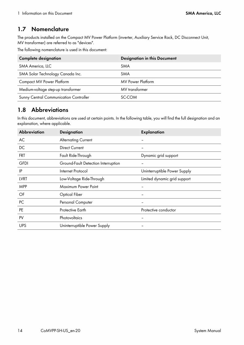
1 Information on this Document SMA America, LLC
14 CoMVPP-SH-US_en-20 System Manual
1.7 NomenclatureThe products installed on the Compact MV Power Platform (inverter, Auxiliary Service Rack, DC Disconnect Unit, MV transformer) are referred to as "devices".The following nomenclature is used in this document:
1.8 AbbreviationsIn this document, abbreviations are used at certain points. In the following table, you will find the full designation and an explanation, where applicable.
Complete designation Designation in this DocumentSMA America, LLC SMASMA Solar Technology Canada Inc. SMACompact MV Power Platform MV Power PlatformMedium-voltage step-up transformer MV transformerSunny Central Communication Controller SC-COM
Abbreviation Designation ExplanationAC Alternating Current ‒DC Direct Current ‒FRT Fault Ride-Through Dynamic grid supportGFDI Ground-Fault Detection Interruption ‒IP Internet Protocol Uninterruptible Power Supply LVRT Low-Voltage Ride-Through Limited dynamic grid supportMPP Maximum Power Point ‒OF Optical Fiber ‒PC Personal Computer ‒PE Protective Earth Protective conductorPV Photovoltaics ‒UPS Uninterruptible Power Supply ‒
SMA America, LLC 2 Safety
System Manual CoMVPP-SH-US_en-20 15
2 SafetyRead this section carefully before starting work. In this section you will find generally applicable, safety-relevant information which you must comply with while carrying out all work on the product. Read this section very carefully in order to prevent personal injury and property damage and to ensure long-term operation of the product.
2.1 Intended UseThe MV Power Platform is a complete system for large-scale PV power plants. All devices required to convert the direct current generated by the PV modules into alternating current and to feed this into the medium-voltage grid are located on the MV Power Platform.The MV Power Platform is suitable for outdoor installation. All devices installed on the MV Power Platform comply with NEMA 3R and are authorized for use under conditions of precipitation.Only persons fulfilling all the skills for the target group are permitted to work on or with the MV Power Platform.The intended use of the MV Power Platform will only be possible if you have read and fully understood this document, especially the Safety section. The MV Power Platform may only be operated providing that the maximum permissible DC input voltage and the permitted ambient conditions are observed. The permissible DC input voltage and the permitted ambient conditions are subject to the respective configuration of the MV Power Platform. Ensure that the maximum permissible DC input voltage and the permitted ambient conditions are complied with prior to commissioning the MV Power Platform.All work on the MV Power Platform must be performed using the appropriate tools and in compliance with the ESD protection regulations.NFPA 70E Table 130.7(C)(16) Hazard Risk Category 2 personal protective equipment is to be worn by all persons working on or with the MV Power Platform.The MV Power Platform must not be installed, operated or maintained by unauthorized persons. Rebuilding, modification or installation of additional components on the MV Power Platform or its constituent devices must not be performed without the express consent of SMA. Any rebuilding, modification or installation of additional components performed with the consent of SMA will be subject to customer liability. SMA does not grant any warranty for such modifications. Unauthorized installations and modifications compromise operational safety and void the operation permission and warranty claims.The MV Power Platform must only be operated when all the installed components are closed, locked and in perfect working order.The devices of the MV Power Platform must not be opened during duststorm, precipitation or at a humidity of over 95%.Any use of the MV Power Platform other than that described in the Intended Use section does not qualify as appropriate.

2 Safety SMA America, LLC
16 CoMVPP-SH-US_en-20 System Manual
2.2 Safety PrecautionsThis section contains safety precautions that must be observed at all times when working on or with the product. To prevent personal injury or property damage and to ensure long-term operation of the product, read this section carefully and follow all safety precautions at all times.
Danger to life from electric shock due to live voltageThere are high voltages present in the MV Power Platform and its components. Touching live components results in death or serious injury due to electric shock.
• When working in a high contact-risk environment, wear Hazard Risk Category 2 personal protective equipment.• Always perform work in compliance with the regulations specified in 29 CFR, Chapter XVII, Part 1910 (OSHA),
NEC, and NFPA 70E.• Do not touch live components.• Follow the instructions precisely.• Observe all safety messages on the product and in the documentation.• Before performing any work on the MV Power Platform, always disconnect all devices whenever live voltage is not
absolutely necessary.• Ensure that no disconnected devices can be reconnected.• After disconnecting the MV Power Platform, wait at least 15 minutes until the MV Power Platform capacitors have
discharged completely.• Before performing any work on the MV Power Platform, ensure that no voltage is present in any of the devices.
Danger to life from electric shock due to live DC cablesDC cables connected to PV modules that are exposed to sunlight are live. Trying to connect live DC cables will result in death or serious injury.
• Wear Hazard Risk Category 2 personal protective equipment for all work on the MV power platform.• Prior to connecting the DC cables, ensure that the DC cables are voltage-free.
Danger to life from electric shock due to ground faultIf a ground fault has occurred, parts of the plant that are supposedly grounded may in fact be live. Touching incorrectly grounded components can result in death or very serious injuries from electric shock.
• Before working on the plant, ensure that no ground fault is present and the GFDI breaker is closed. Ensure that no voltage is present. If there is a possibility of the grounded conductor becoming ungrounded, use additional grounding straps.
• Wear Hazard Risk Category 2 personal protective equipment for all work on the MV power platform.Danger to life from electric shock when entering the PV fieldGround fault monitoring with GFDI and Advanced Remote GFDI does not provide protection from injury when GFDI is activated. PV modules grounded by GFDI discharge voltage to ground. Entering the PV field may lead to lethal electric shocks.
• Before entering the PV field, switch the PV array to insulated operation.• Ensure that the insulation resistance of the PV array is greater than 1 k Ω .
SMA America, LLC 2 Safety
System Manual CoMVPP-SH-US_en-20 17
Danger to life from electric shock if the MV Power Platform is damagedOperating a damaged MV Power Platform can lead to hazardous situations that result in death or serious injuries due to electric shock.
• Only use the MV Power Platform when it is technically faultless and in an operationally safe state.• Regularly check the MV Power Platform for visible damage.• Make sure that all external safety equipment is freely accessible at all times.• Make sure that all safety equipment is in good working order.• Wear Hazard Risk Category 2 personal protective equipment for all work on the MV Power Platform.
Danger to life from electric shock even if the inverter is disconnected on the AC and DC sidesThe precharge unit of the option "" is also live if the AC contactor and the DC switch are open. Touching live components of this assembly will result in death or serious injury.
• Do not touch live components.• Do not remove protective covers.• Observe the warning messages.• Wear Hazard Risk Category 2 personal protective equipment.
Danger to life due to electric shock if devices are left unlockedIf devices are left unlocked, unauthorized persons will have access to components in which lethal voltages are present. Touching live components results in death or serious injury due to electric shock.
• Always close and lock all devices on the MV Power Platform.• Ensure that unauthorized persons do not have access to the plant.
Risk of fire due to failure to observe torque specifications on high-voltage bolted connectionsFailure to follow the specified torques reduces the ampacity of live screw connections so that the contact resistances increase. This can cause components to overheat and catch fire.
• Ensure that high-voltage bolted connections are always executed with the exact torque specified in this document. • Only use suitable tools when working on the device.• Avoid repeated tightening of high-voltage bolted connections as this may result in inadmissibly high torques.
Danger to life due to blocked escape routesIn hazardous situations, blocked escape routes can lead to death or serious injury.
• An escape route with a width of at least 3 ft. (915 mm) must be available at all times.• Do not place any objects in the escape route area.• Remove all tripping hazards from the escape routes.

2 Safety SMA America, LLC
18 CoMVPP-SH-US_en-20 System Manual
Danger of falling from elevated MV Power PlatformIf safety precautions are not observed, the qualified person could fall off MV Power Platform and be injured.
• If the MV Power Platform is elevated, erect catwalks with banisters.• When carrying out any work on the MV Power Platform, always wear suitable personal protective equipment.
Risk of burns due to hot devices or componentsSome devices or components on the MV Power Platform can reach high temperatures during operation. Touching these components can result in burn injuries.
• Observe the safety warnings on the devices.• During operation, do not touch any devices or components marked with such warnings.• After disconnecting the plant, wait until any hot components or devices, e.g., the MV transformer, have cooled
down sufficiently.• When carrying out any work on the MV Power Platform, always wear suitable personal protective equipment.
Damage to the devices due to dust or moisture penetrationDust or moisture penetration can damage the devices of the MV Power Platform or impair their functionality.
• Do not open any devices during a duststorm, precipitation or when humidity exceeds 95%.• Perform maintenance on the devices only when the environment is dry and free of dust.
Damage to electronic components due to electrostatic dischargeElectrostatic discharge can damage or destroy electronic components.
• When working on the MV Power Platform and handling the assemblies, observe the ESD safety regulations.• Wear suitable personal protective equipment for all work on the devices.• Discharge electrostatic charge by touching uncoated, grounded enclosure parts (e.g. at the PE connection on the
doors). Only then is it safe to touch any electronic components.Damage to the devices of the Auxiliary Services Rack due to direct solar irradiation on the back of the Auxiliary Services RackDirect solar irradiation on the back of the Auxiliary Services Rack can cause the devices getting too hot. High temperatures can damage the components or impair their functionality.
• Align the MV Power Platform with the front side of the Auxiliary Services Rack facing East, South or West. This prevents the back of the Auxiliary Services Rack from getting too hot.
Providing a catwalk for MV Power Platforms installed in an elevated position• If the Base Frame of the MV Power Platform is positioned more than 2 in. (50 mm) above ground level for one
of the selected installation types, a catwalk around the platform as well as railings and stairs for the catwalk must be provided for maintenance work and operating the MV Power Platform. The catwalk, railings and stairs must meet the applicable requirements of the OSHA, NEC and AHJ directives.
• The catwalk is to be provided and installed by the customer. The catwalk must be mounted prior to SMA commissioning activities.

SMA America, LLC 2 Safety
System Manual CoMVPP-SH-US_en-20 19
2.3 Personal Protective EquipmentAlways wear the personal protective equipment recommended by SMA America, LLC when working on the MV Power Platform. All clothing should be in accordance with NFPA 70E Section 130.7. Appropriate Insulated gloves for shock protection in accordance with NFPA 70E Section 130.7(C), rated at least 1000V shall be worn as required. Any other prescribed protective equipment must also be used. When carrying out work on live parts of the MV Power Platform, protective equipment of at least Hazard Risk Category 2 is required in accordance with NEMA NFPA 70E, Table 130.7(C)(16).
Hazard Risk Category 2 protective equipment requiredIn accordance to NFPA 70E, an arc flash hazard risk analysis has been performed by SMA, and appropriate Arc Flash Hazard labels stating the required Personal Protective Equipment (PPE) for exposed, energized interaction with the equipment, are installed. Hazard Risk Category 2 PPE is the requirement for all routine maintenance, diagnostics, and commissioning activities as described in the SMA protocols. Areas within the machine also exist that cannot, under any circumstances, be exposed while energized. For additional information, please contact the SMA Service Line.
3 Transport and Mounting SMA America, LLC
20 CoMVPP-SH-US_en-20 System Manual
3 Transport and MountingOnce you have taken all the preparatory measures for installing the MV Power Platform, it can be transported to the mounting location. This section explains which transport options SMA recommends and what precautions you need to take during transport in order to avoid personal injury or property damage.
3.1 Safety Precautions for Transport and Mounting
3.2 Requirement for Transport and Mounting3.2.1 Ambient Conditions The mounting location must be freely accessible at all times. The maximum permissible gradient of the access road is 4%. While unloading the minimum clearances to neighboring obstacles must be observed. All requirements for the ambient conditions must be met (see Section 11 "Technical Data", page 253).
Danger of crushing if the lifted MV Power Platform tips over, falls, or sways during liftingIf the MV Power Platform is lifted and transported too fast or without due care, it may tip over, fall or sway.
• Transport the MV Power Platform as close to the ground as possible.• Do not stand under the lifted MV Power Platform.• Use all suspension points for transportation.• When lifting with a crane, use a hoist which is designed for the weight of the MV Power Platform.• Avoid fast or jerky movements during transport of the MV Power Platform.• Keep a safe distance from the MV Power Platform during transport.• All means of transport used must be designed for the weight of the MV Power Platform.• Do not transport the MV Power Platform using a forklift truck.• Before lifting the MV Power Plattform remove snow and other loads.
Damage to the devices of the Auxiliary Services Rack due to direct solar irradiation on the back of the Auxiliary Services RackDirect solar irradiation on the back of the Auxiliary Services Rack can lead to overheating of the components. High temperatures can damage the components or impair their functionality.
• Align the MV Power Platform with the front side of the Auxiliary Services Rack facing East, South or West. This prevents the back of the Auxiliary Services Rack from getting too hot.
Damage to the MV Power Platform due to improper temporary storageIf the MV Power Platform is not stored appropriately, the frame construction and the devices of the MV Power Platform may be damaged. Dust and moisture can penetrate the devices of the MV Power Platform and damage electronic components.
• Do not place the MV Power Platform on an unstable, uneven surface. • Prior to storage, ensure that the doors of all devices are closed and that the base plates have not been removed.
Damage to the Auxiliary Service Rack during transport due to heavy snow loadSnow on the Auxiliary Services Rack can damage the roof and devices and impair their functions during transport.
• Before transporting remove snow from the Auxiliary Services Rack.

SMA America, LLC 3 Transport and Mounting
System Manual CoMVPP-SH-US_en-20 21
3.2.2 Requirements for Transport by Truck A trailer with a pneumatic suspension has to be used. SMA recommends using a double drop trailer. The MV transformer of the MV Power Platform must be positioned as close as possible to the tractor. The MV Power Platform has to be loaded flat and without further blockings under the MV Power Platform on the
trailer. The MV Power Platform has to be positioned loaded on and unloaded from the trailer suing a heavy-duty crane.
Using forklift trucks is not allowed.
3.2.3 Center of GravityThe center of gravity of the MV Power Platform is not in the middle of the unit. Take this into consideration when transporting the MV Power Platform. The center of gravity varies according to the selected option and power class of the inverters. The exact position of the center of gravity is indicated in the project-specific weight and structural calculation of the MV Power Platform.The lifting lugs are aligned at the MV Power Platform in such a way that safe transport can be guaranteed. The variations of the center of gravity must be compensated accordingly by extending the chains at the lifting lugs using shackles.
3.3 Transporting the MV Power Platform by Crane
Figure 1: Position of the lifting lugs at the MV Power Platform with Disconnect Unit
Figure 2: Position of the lifting lugs at the MV Power Platform without Disconnect Unit

3 Transport and Mounting SMA America, LLC
22 CoMVPP-SH-US_en-20 System Manual
Figure 3: Bolted connection for attaching the lifting lugs
Requirements: The crane and hoist must be suitable for the weight of the MV Power Platform. The hoist is properly attached to the crane.
Procedure:1. Attach the lifting lugs. Only use the screws, nuts and washers included in the scope of delivery (torque for slightly
oiled screws: 708 ft-lbs (960 Nm)). 2. Attach the hoist to all six lifting lugs on the MV Power Platform with
Disconnect Unit.
Position DesignationA NutB Spring washerC ScrewD Lifting lugE MV Power Platform

SMA America, LLC 3 Transport and Mounting
System Manual CoMVPP-SH-US_en-20 23
3. Attach the hoist to all four lifting lugs on the MV Power Platform without Disconnect Unit.
4. Raise the MV Power Platform slowly until the hoist is evenly taut.If the MV Power Platform is not level when raised, lower it back down to the ground.• Make sure that the hoist is properly aligned to ensure that the MV Power Platform can be lifted level. If necessary,
extend the chains of the hoist using shackles to ensure that the MV Power Platform is in a horizontal position. The angle should be smaller than 2°.
5. Ensure that the hoist is attached correctly.6. Raise the MV Power Platform slightly.7. Transport the MV Power Platform to the end location as close to the ground as possible.8. Set the MV Power Platform down. The support surface must be suitable for the weight of the MV Power Platform.9. Prior to road transport, remove the lifting lugs. With lifting lugs attached, the maximum permissible width for road
transport is exceeded.
3.4 Transporting the MV Power Platform by Truck3.4.1 Securing the MV Power Platform for Transport by TruckPrior to transporting the MV Power Platform by truck, it must be adequately secured.
Figure 4: Positions of the tie-down brackets at the MV Power Platform with Disconnect Unit
Comply with manufacturer specificationsWhen using lashing chains or tie-down straps to secure the MV Power Platform, always follow the instructions of the lashing equipment manufacturer.

3 Transport and Mounting SMA America, LLC
24 CoMVPP-SH-US_en-20 System Manual
Figure 5: Positions of the tie down brackets at the MV Power Platform without Disconnect Unit
Requirements: The lifting lugs have been removed from the MV Power Platform. The lifting lugs are properly stowed and secured against slipping.
Procedure:1. Hook the lashing chains into the anchor lugs.2. Attach the tie-down straps to the means of transport.3. Secure the lashing chains and tie-down straps on the means of transport. The lashing chains and tie-down straps must
be sufficiently tensioned. This will prevent the MV Power Platform from slipping during transport.
3.4.2 Preparing the MV Power Platform for Unloading from TruckPrior to unloading the MV Power Platform, certain preparations must be made. Otherwise, you might encounter problems when setting the MV Power Platform down on the installation foundation. Take these preparatory measures in order to avoid damage to cables and conduits.
3.4.2.1 Removing the Base Plates from the MV Power Platform
Figure 6: Position of the base plates and enclosure openings for the MV Power Platform with Disconnect Unit (top view).

SMA America, LLC 3 Transport and Mounting
System Manual CoMVPP-SH-US_en-20 25
Figure 7: Position of the base plates and openings for cable entries at the MV Power Platform without Disconnect Unit (top view).
Figure 8: Position of the base plates (side view)
Requirements: The MV Power Platform must be at the mounting location.
Position DesignationA Base plate of the MV transformerB Base plates of the Disconnect UnitsC Base plates of the Auxiliary Services Rack
Position DesignationA Base plate of the MV transformerB Base plates of the invertersC Base plates of the Auxiliary Services Rack
Position DesignationA Base plates of the Disconnect UnitsB Base plate of the Auxiliary Services Rack

3 Transport and Mounting SMA America, LLC
26 CoMVPP-SH-US_en-20 System Manual
Procedure:• Remove the base plates from the MV Power Platform. Safely store the screws and washers for mounting.
3.4.2.2 Removing the Lashing Chains and Tie-Down Straps
Requirements: The MV Power Platform must be at the mounting location. The base plates are removed (see Section 3.4.2.1, page 24).
Procedure:1. Release the tie-down straps (see relevant documentation).2. Release the lashing chains (see relevant documentation).
3.5 Mounting the MV Power PlatformThe MV Power Platform can be mounted on various foundations. The foundation used must be suitable for the weight of the MV Power Platform (see Section 12.1 "Mounting Information", page 266). There are the following possibilities for the support surface:
• Concrete piers• Concrete beams• Concrete pad• Ballast substructure
In order to facilitate access to the MV Power Platform, SMA recommends inserting the base frame of the MV Power Platform into the ground in such a way that the base frame is flush with the ground level. In the case of the MV Power Platform with the oil tray option, you must take into account that there is enough space for the oil separator and the necessary maintenance work before inserting the MV Power Platform. The customer is responsible for anchoring the MV Power Platform on the support surface. In the following, SMA describes how to attach the MV Power Platform using anchor clips. This type of anchoring is just an example. It is the responsibility of the civil engineer of record to decide on the method of anchoring to be used.
Risk of injury when releasing tie-down straps and lashing chainsSince there is tension on the tie-down straps and lashing chains, there is a risk of whiplash when they are released. This can result in cuts or crushing.
• Ensure that the tie-down straps and lashing chains cannot whiplash when released.• Observe all manufacturer instructions on handling the tie-down straps and lashing chains.
Providing a catwalk for MV Power Platforms installed in an elevated position• If the base frame of the MV Power Platform is positioned more than 2 in. (50 mm) above ground level for one
of the selected installation types, a catwalk around the platform as well as railings and stairs for the catwalk must be provided for maintenance work and operating the MV Power Platform. The catwalk, railings and stairs must meet the applicable requirements of the OSHA, NEC and AHJ directives.
• The catwalk is to be provided and installed by the customer. The catwalk must be mounted prior to SMA commissioning activities.

SMA America, LLC 3 Transport and Mounting
System Manual CoMVPP-SH-US_en-20 27
3.5.1 Transporting the MV Power Platform to the Support SurfaceRequirements: The support surface must be prepared for installation of the MV Power Platform (see Section 12.1, page 266). The MV Power Platform must be prepared for unloading (see Section 3.4.2, page 24). A suitable crane and hoist must be available.
Procedure:1. Transport the MV Power Platform by crane to the support surface (see Section 3.3, page 21).2. Route the connection cables through the base plates into the MV Power Platform. Make sure not to damage the
cables.3. Set the MV Power Platform down on a suitable support surface.
3.5.2 Fastening the MV Power Platform using Anchor ClipsThe MV Power Platform can be attached to the foundation by means of anchor clips. At least six anchor points should be used for the MV Power Platform with Disconnect Unit and the anchor points should located as close as possible to the lifting lugs. For the MV Power Platform without Disconnect Unit at least four anchor points are to be used.The anchor clips are not included in the scope of delivery and must be provided by the customer.
Figure 9: Optimum anchoring points for the anchor clips of the MV Power Platform with Disconnect Unit.
Figure 10: Optimum anchoring points for the anchor clips of the MV Power Platform without Disconnect Unit.
Position DesignationA Optimum anchoring points for anchor clips
Position DesignationA Optimum anchoring points for anchor clips
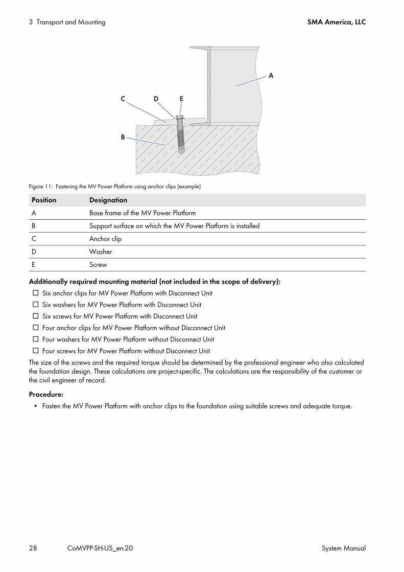
3 Transport and Mounting SMA America, LLC
28 CoMVPP-SH-US_en-20 System Manual
Figure 11: Fastening the MV Power Platform using anchor clips (example)
Additionally required mounting material (not included in the scope of delivery): Six anchor clips for MV Power Platform with Disconnect Unit Six washers for MV Power Platform with Disconnect Unit Six screws for MV Power Platform with Disconnect Unit Four anchor clips for MV Power Platform without Disconnect Unit Four washers for MV Power Platform without Disconnect Unit Four screws for MV Power Platform without Disconnect Unit
The size of the screws and the required torque should be determined by the professional engineer who also calculated the foundation design. These calculations are project-specific. The calculations are the responsibility of the customer or the civil engineer of record.Procedure:
• Fasten the MV Power Platform with anchor clips to the foundation using suitable screws and adequate torque.
Position DesignationA Base frame of the MV Power PlatformB Support surface on which the MV Power Platform is installedC Anchor clipD WasherE Screw

SMA America, LLC 4 Installation
System Manual CoMVPP-SH-US_en-20 29
4 Installation4.1 Safety during InstallationIn this section, you will find safety precautions which you must observe throughout the entire process of making the DC connection. Read this section carefully and follow the instructions to prevent personal injury and property damage and to ensure smooth operation of the inverter. The DC inputs are isolated from the enclosure and the system grounding. If required by section 250 of the National Electrical Code®, ANSI/NFPA 70, the installer is responsible for this grounding.

4 Installation SMA America, LLC
30 CoMVPP-SH-US_en-20 System Manual
Danger to life from electric shock due to live voltageThere are high voltages present in the MV Power Platform and its components. Touching live components results in death or serious injury due to electric shock.
• When working in a high contact-risk environment, wear Hazard Risk Category 2 personal protective equipment.• Always perform work in compliance with the regulations specified in 29 CFR, Chapter XVII, Part 1910 (OSHA),
NEC, and NFPA 70E.• Do not touch live components.• Follow the instructions precisely.• Observe all safety messages on the product and in the documentation.• Before performing any work on the MV Power Platform, always disconnect all devices whenever live voltage is not
absolutely necessary.• Ensure that no disconnected devices can be reconnected by following an OSHA-compliant lockout-tagout
procedure.• After disconnecting the MV Power Platform, wait at least 15 minutes until the inverter capacitors have discharged
completely.• Before performing any work on the MV Power Platform, ensure that no voltage is present in any of the devices.• Entry to specially marked areas is prohibited when they are live.
Danger to life from electric shock due to live DC cablesDC cables connected to PV modules that are exposed to sunlight are live. Trying to connect live DC cables will result in death or serious injury.
• Prior to connecting the DC cables, ensure that the DC cables are voltage-free.• When carrying out any work on the MV Power Platform, wear Hazard Risk Category 2 personal protective
equipment.•
Danger to life from electric shock due to live AC voltageHigh voltages are present in the live components of the low-voltage and medium-voltage grids. Touching live components results in death or serious injury.
• Observe all safety regulations for working with the low-voltage and medium-voltage grid.• Disconnect the AC and DC circuit breakers and ensure that they cannot be accidentally reconnected by following
an OSHA-compliant Lockout-Tagout procedure.• Disconnect the MV Power Platform from the DC sub-distributions and DC main distribution.• Ensure that no voltage is present.• When carrying out any work on the MV Power Platform, wear Hazard Risk Category 2 personal protective
equipment.

SMA America, LLC 4 Installation
System Manual CoMVPP-SH-US_en-20 31
Risk of fire due to insufficiently dimensioned connection cablesIf the ampacity of the connection cables is too low, they can overheat and pose a fire risk.
• All cable cross-sections must be designed for the maximum possible current.• All cables must be laid in compliance with the local regulations.• The stipulated ambient conditions must be complied with.• Only use aluminum cables or copper cables.
Risk of fire due to faulty connections or oxidized contact surfacesIn case of faulty connections or oxidized contact surfaces, sufficient ampacity can no longer be ensured. This may result in connections being subject to overheating and fire hazard.
• Only use the nuts, screws and washers included in the scope of delivery for the connection.• Only use tin-plated terminal lugs.• The fender washers and spring washers must not protrude the terminal lug.• Always connect two-hole terminal lugs using two screws.• Before connecting the cables, clean the contact surfaces.• Do not touch the cleaned contact surfaces.• Always adhere to the specified torque when establishing the connections.
Risk of fire due to failure to observe torque specifications on live bolted connectionFailure to follow the specified torques reduces the ampacity of live bolted connections so that the contact resistances increase. This can cause components to overheat and catch fire.
• Ensure that live bolted connections are always executed with the exact torque specified in this document. • Only use suitable tools when working on the device.• Avoid repeated tightening of live bolted connections as this may result in inadmissibly high torques.
Risk of burns due to hot componentsThe components and devices of the MV Power Platform can reach high temperatures. Touching these components can result in burns.
• Do not touch hot components.• Wait until hot components have sufficiently cooled down.• Observe the safety warnings on the MV Power Platform and its devices.• When carrying out any work on the MV Power Platform and its devices, wear Hazard Risk Category 2 personal
protective equipment.
Damage to electronic components due to electrostatic dischargeElectrostatic discharge can damage or destroy electronic components.
• Observe the ESD safety regulations when working on the device.• When carrying out any work on the MV Power Platform and its devices, wear Hazard Risk Category 2 personal
protective equipment.• Neutralize any electrostatic charge before touching electronic components, for example, by touching the
grounding connection of the doors.

4 Installation SMA America, LLC
32 CoMVPP-SH-US_en-20 System Manual
4.2 Sequence of Installation WorkThe sequence of installation work given in this section is recommended by SMA. It is important to begin the installation with the preparatory work and the grounding connection. Therefore, SMA recommends that you adhere to this sequence to avoid problems during the installation.
Recommended procedure:1. Preparatory work2. Grounding connection at the base frame3. Grounding connection in the Disconnect Units
orGrounding connection in the inverters
4. AC connection in the MV transformer5. Cable connection for supply voltage, communication and control systems on the Auxiliary Services Rack6. DC connection in the Disconnect Units
orDC connection in the inverters
4.3 Preparatory WorkIn order to ensure that the installation runs as smoothly as possible, SMA recommends performing certain preparatory work prior to beginning with the installation work.
4.3.1 Removing the Transport Locks• Remove the packaging from the Auxiliary Services Rack and from the air ducts of the Sunny Central inverters.
4.3.2 Preparing the Cable EntryPrior to starting the actual installation work, prepare the interface gland plates for cable entry.

SMA America, LLC 4 Installation
System Manual CoMVPP-SH-US_en-20 33
4.3.2.1 Position of the Base Plates
MV Power Platform with Disconnect Unit
Figure 12: Position of the base plates on the MV Power Platform with Disconnect Unit
MV Power Platform without Disconnect Unit
Figure 13: Position of the base plates on the MV Power Platform without Disconnect Unit
Position DesignationA Base plate of MV transformerB Base plates of the Disconnect Units C Base plates of the Auxiliary Services Rack
Position DesignationA Base plate of MV transformer
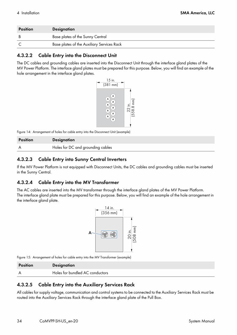
4 Installation SMA America, LLC
34 CoMVPP-SH-US_en-20 System Manual
4.3.2.2 Cable Entry into the Disconnect UnitThe DC cables and grounding cables are inserted into the Disconnect Unit through the interface gland plates of the MV Power Platform. The interface gland plates must be prepared for this purpose. Below, you will find an example of the hole arrangement in the interface gland plates.
Figure 14: Arrangement of holes for cable entry into the Disconnect Unit (example)
4.3.2.3 Cable Entry into Sunny Central InvertersIf the MV Power Platform is not equipped with Disconnect Units, the DC cables and grounding cables must be inserted in the Sunny Central.
4.3.2.4 Cable Entry into the MV TransformerThe AC cables are inserted into the MV transformer through the interface gland plates of the MV Power Platform. The interface gland plate must be prepared for this purpose. Below, you will find an example of the hole arrangement in the interface gland plate.
Figure 15: Arrangement of holes for cable entry into the MV Transformer (example)
4.3.2.5 Cable Entry into the Auxiliary Services Rack All cables for supply voltage, communication and control systems to be connected to the Auxiliary Services Rack must be routed into the Auxiliary Services Rack through the interface gland plate of the Pull Box.
B Base plates of the Sunny CentralC Base plates of the Auxiliary Services Rack
Position DesignationA Holes for DC and grounding cables
Position DesignationA Holes for bundled AC conductors
Position Designation

SMA America, LLC 4 Installation
System Manual CoMVPP-SH-US_en-20 35
4.3.2.6 Punching the Holes in the Base PlatesRequirements: The MV Power Platform must be at the final installation site. The base plates must be removed (see Section 3.4.2.1, page 24). If the cables are not laid in a concrete plate, they must be routed in conduits.
Additionally required mounting material (not included in the scope of delivery): Suitable tool for punching the holes in the base plates (e.g., stamping tool).
Procedure:1. Mark all holes for conduits on the base plate in accordance with the cable arrangement.2. Punch the holes.
4.4 Installing the Grounding Cable in the Base Platform4.4.1 Connection OverviewThe MV Power Platform is equipped at two points with grounding pads which provide the possibility of external grounding. The grounding pads made of stainless steel are connected by cable from the grounding busbar in the MV transformer.The external grounding must be executed by the customer on-site in accordance with the grounding concept of the entire PV system. Influencing factors are the conditions or conductivity of the soil, the lightning protection system and the type of ground electrode. The ground electrodes can, for instance, be executed as grounding straps or grounding electrodes.
MV Power Platform with Disconnect Unit
Figure 16: Position of the grounding points of the MV Power Platform with Disconnect Unit
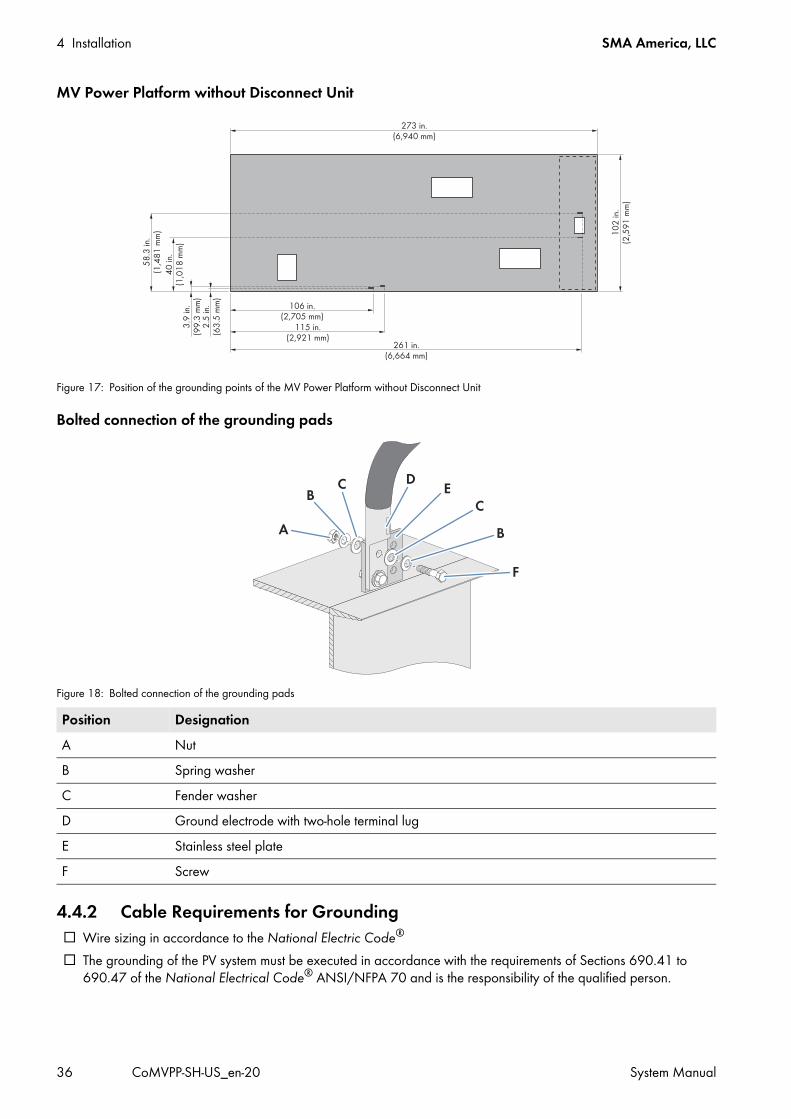
4 Installation SMA America, LLC
36 CoMVPP-SH-US_en-20 System Manual
MV Power Platform without Disconnect Unit
Figure 17: Position of the grounding points of the MV Power Platform without Disconnect Unit
Bolted connection of the grounding pads
Figure 18: Bolted connection of the grounding pads
4.4.2 Cable Requirements for Grounding Wire sizing in accordance to the National Electric Code®
The grounding of the PV system must be executed in accordance with the requirements of Sections 690.41 to 690.47 of the National Electrical Code® ANSI/NFPA 70 and is the responsibility of the qualified person.
Position DesignationA NutB Spring washerC Fender washerD Ground electrode with two-hole terminal lugE Stainless steel plateF Screw

SMA America, LLC 4 Installation
System Manual CoMVPP-SH-US_en-20 37
4.4.3 Connecting the Grounding PadsRequirements: All cable requirements must be complied with. Any additionally required material must be available.
Additionally required mounting material (not included in the scope of delivery): Screws, M12 Spring washers, external diameter: 29 mm, internal diameter: 13.5 mm, thickness: 1.25 mm Fender washers, external diameter: 32 mm, internal diameter: 13 mm Nuts, M12 Ground electrodes of the PV system suitable for the grounding concept of the PV system Clean cloth Ethanol cleaning agent Non-woven abrasive Suitable material for sealing the grounding pads (e.g. durable zinc paint)
Procedure:1. Install the ground electrode of the PV system in accordance with the applicable regulations.2. Ensure that the required grounding resistance is reached.3. If insulated grounding cables are used, strip the insulation off the cables.4. Fit the grounding cables with terminal lugs.5. Clean the contact surfaces with the non-woven abrasive until they have a light metallic sheen. At the same time,
ensure that the coated contact surfaces are not damaged.6. Clean the contact surfaces using a clean cloth and ethanol cleaning agent.7. Remove metal dust with a clean cloth. 8. Do not touch the cleaned contact surfaces.9. Connect the grounding cables to the grounding pads.
10. Connect the grounding cables to the ground electrodes of the PV system.11. Seal the grounding pads and terminals.
Grounding the MV Power PlatformGround the MV Power Platform in accordance with the applicable regulations.There are two ground connections provided on the MV Power Platform. SMA recommends connecting both grounding pads to the ground electrode of the PV system.

4 Installation SMA America, LLC
38 CoMVPP-SH-US_en-20 System Manual
4.5 Installing the Grounding Cable in the Disconnect Unit4.5.1 Overview of the Connection Area
Figure 19: Connection area of the Disconnect Unit
4.5.2 Cable Requirements for Cables and Terminal LugsIn addition to the general cable requirements (see Section 12.3.1, page 271), the following requirements are applicable:Cables: Conductor ampacity must comply with NEC articles 310 and 690.
Terminal lugs: Connect a maximum of two cables to one terminal position on the grounding busbar.
4.5.3 Connecting the Grounding Cables in Disconnect UnitRequirements: Preparation of the base plate of the Disconnect Unit must be complete (see Section 4.3.2, page 32). The grounding cables must be inserted into the Disconnect Unit through conduits (see Section 9.2.1, page 167),
if the cables are not laid in a concrete plate.
Position DesignationA Grounding busbar
Information on torquesThe torques specified in the following table are the torques used to mount the terminal lugs to the copper bar.Connection option Cable cross-section TorqueCable connection with aluminum terminal lugs 4 AWG to 800 kcmil
(25 mm2 to 405 mm2)27.5 ft.-lbs. (37 Nm)
Cable connection with copper terminal lugs 4 AWG to 800 kcmil (25 mm2 to 405 mm2)
44.5 ft.-lbs. (60 Nm)
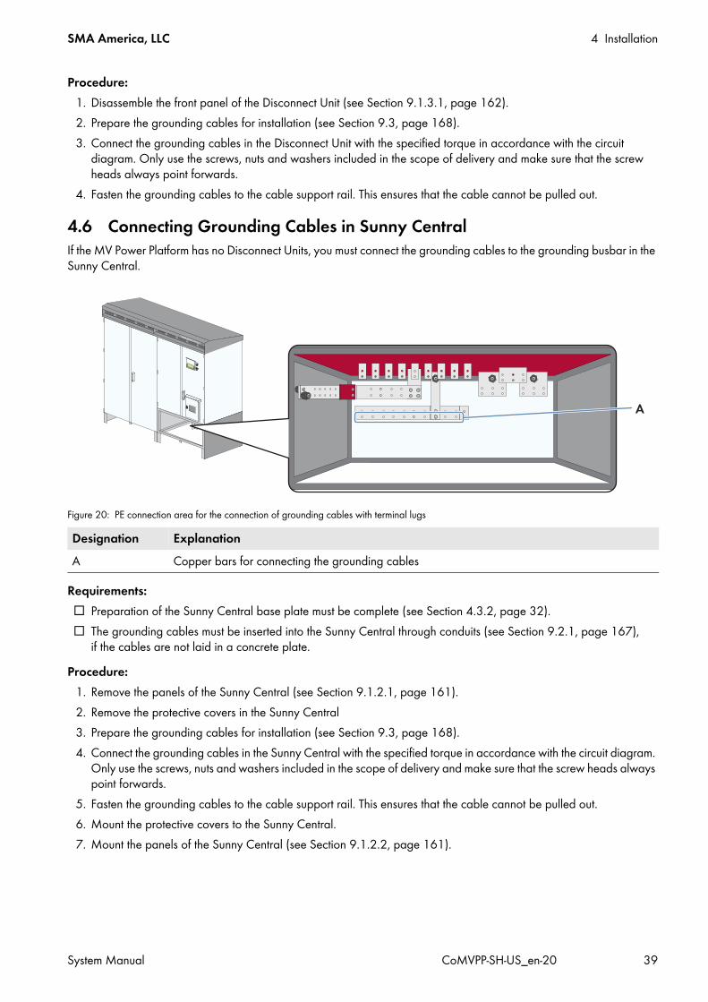
SMA America, LLC 4 Installation
System Manual CoMVPP-SH-US_en-20 39
Procedure:1. Disassemble the front panel of the Disconnect Unit (see Section 9.1.3.1, page 162).2. Prepare the grounding cables for installation (see Section 9.3, page 168).3. Connect the grounding cables in the Disconnect Unit with the specified torque in accordance with the circuit
diagram. Only use the screws, nuts and washers included in the scope of delivery and make sure that the screw heads always point forwards.
4. Fasten the grounding cables to the cable support rail. This ensures that the cable cannot be pulled out.
4.6 Connecting Grounding Cables in Sunny CentralIf the MV Power Platform has no Disconnect Units, you must connect the grounding cables to the grounding busbar in the Sunny Central.
Figure 20: PE connection area for the connection of grounding cables with terminal lugs
Requirements: Preparation of the Sunny Central base plate must be complete (see Section 4.3.2, page 32). The grounding cables must be inserted into the Sunny Central through conduits (see Section 9.2.1, page 167),
if the cables are not laid in a concrete plate.Procedure:
1. Remove the panels of the Sunny Central (see Section 9.1.2.1, page 161).2. Remove the protective covers in the Sunny Central3. Prepare the grounding cables for installation (see Section 9.3, page 168).4. Connect the grounding cables in the Sunny Central with the specified torque in accordance with the circuit diagram.
Only use the screws, nuts and washers included in the scope of delivery and make sure that the screw heads always point forwards.
5. Fasten the grounding cables to the cable support rail. This ensures that the cable cannot be pulled out.6. Mount the protective covers to the Sunny Central.7. Mount the panels of the Sunny Central (see Section 9.1.2.2, page 161).
Designation ExplanationA Copper bars for connecting the grounding cables

4 Installation SMA America, LLC
40 CoMVPP-SH-US_en-20 System Manual
4.7 Installing the AC Connection in the MV Transformer4.7.1 Safety during AC Connection
4.7.1.1 Overview of the Connection Area
Figure 21: Connection area of the MV transformer
Danger to life due to electric shockHigh voltage is present on the medium-voltage side. Touching live components results in death or serious injury.
• All work on the medium-voltage side of the MV transformer is to be carried out by duly authorized persons only.• Work on the medium-voltage side is only permitted providing that the medium-voltage side is disconnected by
means of an upstream switching device and that this switching device has been secured against reconnection.• Always perform work in compliance with the regulations specified in 29 CFR, Chapter XVII, Part 1910 (OSHA),
NEC, NFPA 70E and any locally applicable provisions.Danger to life due to electric shock when live components are touched
• Adhere to the disconnection procedure specified in the documentation of the MV transformer (see the documentation of the medium-voltage switching device).
• Do not operate the load-break switch if a fault condition is suspected. Doing so can cause an explosion or fire.• Use a hotstick to operate load-break device of the MV transformer. • After operating the load-break switch of the MV transformer, check that voltages at transformer terminals are the
expected values. Checking voltages verifies that the load-break switch is operated properly and that electrical circuit conditions are as expected.
• Before servicing transformer secondary connected equipment, verify that no voltage is present at all transformer secondary terminals and ground the transformer secondary terminals following industry accepted safe grounding practices. Grounding secondary terminals protects against situations such as a standby generator energizing transformer from the secondary circuit.
• Before servicing transformer, always de-energize the transformer from a remote upstream source and then proceed to ground all primary and secondary transformer terminals following industry accepted safe grounding practices. Grounding secondary terminals protects against situations such as a standby generator energizing transformer from the secondary circuit.
• Follow industry accepted safety practices. Use protective clothing and equipment when working with load-break equipment.
• Ground the outgoing feeder section.• Ensure that no voltage is present.

SMA America, LLC 4 Installation
System Manual CoMVPP-SH-US_en-20 41
4.7.1.2 Position of the Deadbreak BushingsThe position of the deadbreak bushings can vary depending on the type of MV transformer used. Refer to the MV transformer documentation.
Figure 22: Designation of pin connector positions (example)
4.7.1.3 Circuit DiagramRefer to this circuit diagram when connecting the MV transformer to the medium-voltage grid.
Figure 23: Circuit diagram (example)

4 Installation SMA America, LLC
42 CoMVPP-SH-US_en-20 System Manual
4.7.1.4 Connecting the AC CablesLead the AC cables on the medium-voltage side of the MV transformer through the interface gland plates under the MV transformer and connect them to the MV transformer.
Requirements: No voltage must be present in the AC cables. Preparation of the interface gland plate of the MV transformer must be complete (see Section 4.3.2.4, page 34). The AC cables must be routed into the MV transformer through conduits (see Section 9.2.1, page 167).
Additional tools required: Hotstick
Procedure:1. Ensure that all devices of the MV Power Platform are voltage-free.2. Connect the AC cables on the medium-voltage side in accordance with the circuit diagrams included with the
MV Power Platform.
4.8 Checking the Cable Connection for Supply Voltage, Communication and Control Systems
4.8.1 Overview of the Auxiliary Services RackThe Auxiliary Services Rack is an optional component of the MV Power Platform.The Auxiliary Services Rack is made up of various optional modules. Subject to your specific project, the Auxiliary Services Rack may not include all the modules.The connections for the control system must be executed separately for each inverter. As a result, the inverters can each be switched independently. The control terminals are:
• Remote shutdown• External fast stop• External setpoint• External insulation monitoring
Danger to life due to electric shock by touching live components• Disconnect the medium voltage at the transfer station.• All work on the MV Power Platform and its devices is permitted only when they are disconnected and free of
voltage. • Always follow the instruction on the electric arc safety labeling included on the MV Power Platform.• When operating the load-break switch, always use a hotstick.• Wear suitable personal protective equipment.
Authorization for switching the MV transformerOnly an authorized person trained in electrical safety and appropriate voltage levels is allowed to connect or disconnect the AC voltage of the MV transformer. To do this, use the medium-voltage switch on the MV transformer on the medium-voltage side.
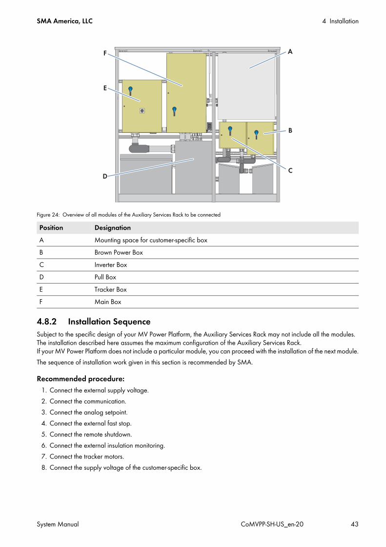
SMA America, LLC 4 Installation
System Manual CoMVPP-SH-US_en-20 43
Figure 24: Overview of all modules of the Auxiliary Services Rack to be connected
4.8.2 Installation SequenceSubject to the specific design of your MV Power Platform, the Auxiliary Services Rack may not include all the modules. The installation described here assumes the maximum configuration of the Auxiliary Services Rack. If your MV Power Platform does not include a particular module, you can proceed with the installation of the next module.The sequence of installation work given in this section is recommended by SMA.
Recommended procedure:1. Connect the external supply voltage.2. Connect the communication.3. Connect the analog setpoint.4. Connect the external fast stop.5. Connect the remote shutdown.6. Connect the external insulation monitoring.7. Connect the tracker motors.8. Connect the supply voltage of the customer-specific box.
Position DesignationA Mounting space for customer-specific boxB Brown Power BoxC Inverter BoxD Pull BoxE Tracker BoxF Main Box
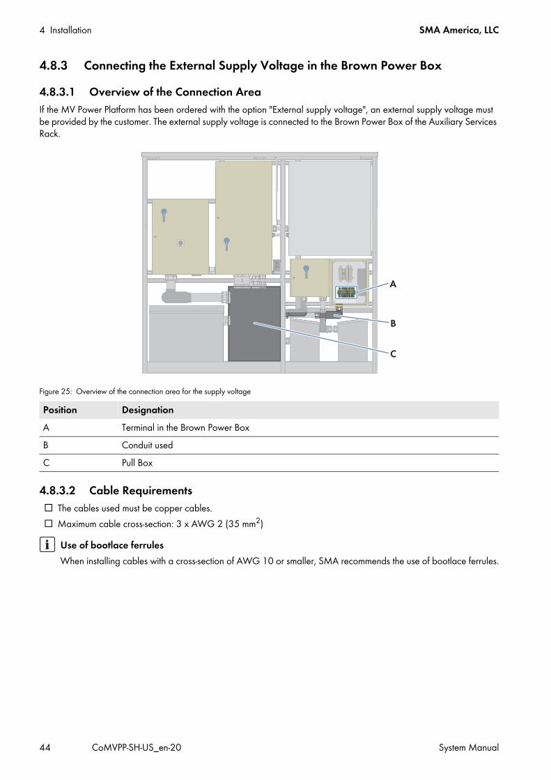
4 Installation SMA America, LLC
44 CoMVPP-SH-US_en-20 System Manual
4.8.3 Connecting the External Supply Voltage in the Brown Power Box4.8.3.1 Overview of the Connection AreaIf the MV Power Platform has been ordered with the option "External supply voltage", an external supply voltage must be provided by the customer. The external supply voltage is connected to the Brown Power Box of the Auxiliary Services Rack.
Figure 25: Overview of the connection area for the supply voltage
4.8.3.2 Cable Requirements The cables used must be copper cables. Maximum cable cross-section: 3 x AWG 2 (35 mm2)
Position DesignationA Terminal in the Brown Power BoxB Conduit usedC Pull Box
Use of bootlace ferrulesWhen installing cables with a cross-section of AWG 10 or smaller, SMA recommends the use of bootlace ferrules.

SMA America, LLC 4 Installation
System Manual CoMVPP-SH-US_en-20 45
4.8.3.3 Inserting and Connecting the CablesRequirements: Preparation of the Pull Box base plate must be complete (see Section 4.3.2, page 32). The cable requirements must be complied with. No voltage must be present on the MV Power Platform.
Procedure:1. Open the Pull Box and the Brown Power Box.2. Insert the cables through the Pull Box.3. Insert the cables through the conduits into the Brown Power Box.4. Connect the cables in the Brown Power Box in accordance with the circuit diagram (see Section 9.4, page 171).5. Secure the cables using cable ties.6. Close the Pull Box and the Brown Power Box.
4.8.4 Connecting the Communication in the Main Box4.8.4.1 Structure of the Communication NetworkThe communication network of the MV Power Platform enables the parameterization, monitoring and remote diagnosis of the MV Power Platform via computer, as well as power control by the grid operator. The communication network can be set up in ring topology.The various tasks can be organized in two separate networks:
• Control network: This network is used by the Power Reducer Box or SMA Power Plant Controller to transmit grid management specifications issued by the grid operator to the inverters. The control network is used exclusively for grid management services which are thus transmitted and implemented within the specified time period. If only a low data transfer rate is required for monitoring the PV system, grid operator specifications can also be transmitted via the monitoring network. In this case, only one network is necessary.
• Monitoring network: this network is used for monitoring, parameterization and remote diagnosis.On the MV Power Platform, there are two optical fiber inputs and two optical fiber outputs. The network is based exclusively on optical fibers.If you integrate the MV Power Platform permanently into a network with Internet access, it will be able to transmit data to Sunny Portal automatically.

4 Installation SMA America, LLC
46 CoMVPP-SH-US_en-20 System Manual
Figure 26: Structure of the communication network of a PV system
4.8.4.2 Overview of the Connection AreaThe MV Power Platform must be connected to the communication network of the PV system. To do this, the data cables must be connected in the Auxiliary Services Rack. The connection between the inverters and the Auxiliary Services Rack has already been installed.
Figure 27: Overview of the connection area for the communication connections
SMA America, LLC 4 Installation
System Manual CoMVPP-SH-US_en-20 47
4.8.4.3 Connecting the Communication in the Main Box Using Optical Fibers
To connect the communication to the MV Power Platform, the optical fibers must be inserted and connected at the splice box located in the Main Box. The splice box is equipped with SC-P plugs to which the optical fibers can be directly connected.There are two ways of connecting the optical fiber to the SC-P plug:
• Connection of optical fibers via SC plug• Connection of optical fibers via optical fiber pigtail
Connecting the Optical Fiber with SC PlugAdditionally required mounting material (not included in the scope of delivery): Four SC plugs (one plug per optical fiber)
Requirements: Preparation of the Pull Box base plate must be complete. No voltage must be present on the MV Power Platform.
Procedure:1. Open the Pull Box and the Main Box.2. Insert the optical fibers through the Pull Box.3. Insert the optical fibers into the Main Box through the right-hand conduit.4. Mount the SC plugs to the optical fibers. 5. Connect the SC plugs to the SC-P plug in the splice box in accordance with the circuit diagram.6. Secure optical fibers with cable ties.7. Close the Pull Box and the Main Box.
Connecting the Optical Fiber via PigtailOptical fiber pigtail requirements: The pigtail cable must be equipped with a 50 μm multi-mode optical fiber. The optical fiber pigtail cable must be fitted with an SC plug.
Additionally required mounting material (not included in the scope of delivery): Four optical fiber pigtails in accordance with the specifications (one pigtail per optical fiber)
Position DesignationA Splice box in the Main BoxB Conduit usedC Pull Box
Damage to optical fibers due to too tight bend radiiExcessive bending or kinking will damage the optical fiber. As a result, signals cannot be transmitted and the communication can fail.
• Observe the minimum permissible bend radii of the optical fibers.

4 Installation SMA America, LLC
48 CoMVPP-SH-US_en-20 System Manual
Requirements: Preparation of the Pull Box base plate must be complete. No voltage must be present on the MV Power Platform.
Procedure:1. Open the Pull Box and the Main Box.1. Insert the optical fibers through the Pull Box.2. Insert the optical fibers into the Main Box through the right-hand conduit.3. Splice the optical fibers with the optical fiber pigtails in the splice box.4. Connect the SC plugs to the SC-P plug in the splice box in accordance with the circuit diagram.5. Secure optical fibers with cable ties.6. Close the Pull Box and the Main Box.
4.8.5 Connecting Analog Setpoints in the Main Box4.8.5.1 Overview of the Connection AreaIf grid management is to use the analog setpoints issued by the grid operator, you can connect the analog setpoints in the Auxiliary Services Rack in accordance with the circuit diagram.
Figure 28: Overview of the connection area for connection of analog setpoints
Position DesignationA Terminal used in the Main BoxB Conduit usedC Pull Box

SMA America, LLC 4 Installation
System Manual CoMVPP-SH-US_en-20 49
4.8.5.2 Cable Requirements The cables used must be shielded against 600 V. Maximum cable cross-section: 2 x AWG 12 (4 mm2)
4.8.5.3 Inserting and Connecting the CablesRequirements: Preparation of the Pull Box base plate must be complete (see Section 4.3.2, page 32). The cable requirements must be complied with. No voltage must be present on the MV Power Platform.
Procedure:1. Open the Pull Box and the Main Box.2. Insert the cables through the Pull Box.3. Insert the cables into the Main Box through the conduit.4. Connect the cables in the Main Box in accordance with the circuit diagram (see Section 9.4, page 171).5. Secure the cables with the cable tie.6. Close the Pull Box and the Main Box.
4.8.6 Connecting the External Fast Stop in the Main Box4.8.6.1 Overview of the Connection AreaIf an external fast stop is required, you can connect the external fast stop in the Auxiliary Services Rack in accordance with the circuit diagram.
Figure 29: Overview of the connection area for connection of the external fast stop
Use of bootlace ferrulesWhen installing cables with a cross-section of AWG 10 or smaller, SMA recommends the use of bootlace ferrules.

4 Installation SMA America, LLC
50 CoMVPP-SH-US_en-20 System Manual
4.8.6.2 Cable Requirements The cables used must be shielded against 600 V. Maximum cable cross-section: 2 x AWG 12 (4 mm2)
4.8.6.3 Inserting and Connecting the CablesRequirements: Preparation of the Pull Box base plate must be complete (see Section 4.3.2, page 32). The cable requirements must be complied with. No voltage must be present on the MV Power Platform.
Procedure:1. Open the Pull Box and the Main Box.2. Insert the cables through the Pull Box and secure with cable ties.3. Insert the cables into the Main Box through the conduit.4. Connect the cables in the Main Box in accordance with the circuit diagram (see Section 9.4, page 171).5. Close the Pull Box and the Main Box.
Position DesignationA Terminal used in the Main BoxB Conduit usedC Pull Box
Use of bootlace ferrulesWhen installing cables with a cross-section of AWG 10 or smaller, SMA recommends the use of bootlace ferrules.

SMA America, LLC 4 Installation
System Manual CoMVPP-SH-US_en-20 51
4.8.7 Connecting the Remote Shutdown in the Main Box4.8.7.1 Overview of the Connection AreaThe remote shutdown enables the MV Power Platform to be switched off from a distance, e.g., from a control room. The remote shutdown function is similar to the fast stop function of the key switch.
Figure 30: Overview of the connection area for connection of the remote shutdown
4.8.7.2 Cable Requirements The cables used must be shielded. Maximum cable cross-section: 2 x AWG 12 (4 mm2)
4.8.7.3 Inserting and Connecting the CablesRequirements: Preparation of the Pull Box base plate must be complete (see Section 4.3.2, page 32). The cable requirements must be complied with. No voltage must be present on the MV Power Platform.
Position DesignationA Terminal used in the Main BoxB Conduit usedC Pull Box
Use of bootlace ferrulesWhen installing cables with a cross-section of AWG 10 or smaller, SMA recommends the use of bootlace ferrules.

4 Installation SMA America, LLC
52 CoMVPP-SH-US_en-20 System Manual
Procedure:1. Open the Pull Box and the Main Box.2. Insert the cables through the Pull Box and secure with cable ties.3. Insert the cables into the Main Box through the conduits.4. Connect the cables in the Main Box in accordance with the circuit diagram (see Section 9.4, page 171).5. Attach the cables to the cable support rail using cable ties. This ensures that the cable cannot be pulled out.6. Close the Pull Box and the Main Box.
4.8.8 Connecting the Insulation Monitoring in the Main Box4.8.8.1 Overview of the Connection AreaThe optional insulation measuring device emits a warning if the PV field does not have sufficient insulation resistance. This warning signal can be tapped via a potential-free relay contact (changeover contact).
Figure 31: Overview of the connection area for connection of the external insulation monitoring
4.8.8.2 Cable Requirements The cables used must be shielded. Maximum cable cross-section: 2 x AWG 8 (10 mm2)
Position DesignationA Terminal used in the Main BoxB Conduit usedC Pull Box
Use of bootlace ferrulesWhen installing cables with a cross-section of AWG 10 or smaller, SMA recommends the use of bootlace ferrules.

SMA America, LLC 4 Installation
System Manual CoMVPP-SH-US_en-20 53
4.8.8.3 Inserting and Connecting the CablesRequirements: Preparation of the Pull Box base plate must be complete (see Section 4.3.2, page 32). The cable requirements must be complied with. No voltage must be present on the MV Power Platform.
Procedure:1. Open the Pull Box and the Main Box.2. Insert the cables through the Pull Box and secure with cable ties.3. Insert the cables into the Main Box through the conduits.4. Connect the cables in the Main Box in accordance with the circuit diagram (see Section 9.4, page 171).5. Close the Pull Box and the Main Box.
4.8.9 Connecting the Tracker Motors in the Tracker Box4.8.9.1 Overview of the Connection AreaYou can connect the cables of the tracker motors in the Tracker Box. PV modules with tracking function are typically driven by tracker motor.
Figure 32: Overview of the connection area for connection of the Tracker Box
Position DesignationA Terminal used in the Tracker BoxB Conduit usedC Pull Box
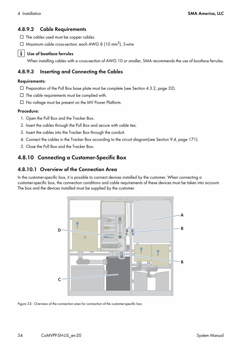
4 Installation SMA America, LLC
54 CoMVPP-SH-US_en-20 System Manual
4.8.9.2 Cable Requirements The cables used must be copper cables. Maximum cable cross-section: each AWG 8 (10 mm2), 3-wire
4.8.9.3 Inserting and Connecting the CablesRequirements: Preparation of the Pull Box base plate must be complete (see Section 4.3.2, page 32). The cable requirements must be complied with. No voltage must be present on the MV Power Platform.
Procedure:1. Open the Pull Box and the Tracker Box.2. Insert the cables through the Pull Box and secure with cable ties.3. Insert the cables into the Tracker Box through the conduit.4. Connect the cables in the Tracker Box according to the circuit diagram(see Section 9.4, page 171).5. Close the Pull Box and the Tracker Box.
4.8.10 Connecting a Customer-Specific Box4.8.10.1 Overview of the Connection AreaIn the customer-specific box, it is possible to connect devices installed by the customer. When connecting a customer-specific box, the connection conditions and cable requirements of these devices must be taken into account. The box and the devices installed must be supplied by the customer.
Figure 33: Overview of the connection area for connection of the customer-specific box
Use of bootlace ferrulesWhen installing cables with a cross-section of AWG 10 or smaller, SMA recommends the use of bootlace ferrules.

SMA America, LLC 4 Installation
System Manual CoMVPP-SH-US_en-20 55
4.8.10.2 Inserting and Connecting the CablesRequirements: Preparation of the Pull Box base plate must be complete (see Section 4.3.2, page 32). The cable requirements of the devices to be connected must be complied with. No voltage must be present on the MV Power Platform.
Procedure:1. Open the Pull Box and the customer-specific box.2. Insert the cables through the Pull Box and secure with cable ties.3. Insert the cables into the customer-specific box through the conduits.4. Connect the cables in the customer-specific box in accordance with the customer's circuit diagram.5. If necessary, connect the supply voltage for the customer-specific box in the Main Box.6. Close the Pull Box and the customer-specific box.
Position DesignationA Mounting space for customer-specific boxB Conduits usedC Pull BoxD Terminal for connecting the supply voltage of the customer-specific box
4 Installation SMA America, LLC
56 CoMVPP-SH-US_en-20 System Manual
4.9 Installing the DC Connection4.9.1 Safety during DC Connection
Danger to life from electric shock due to live voltageThere are high voltages present in the MV Power Platform and its devices. Touching live components results in death or serious injury.
• Never remove the protective covers while the devices are live.• Whenever possible, work only on disconnected equipment, following the disconnection procedures outlined in this
manual, and OSHA compliant lockout-tagout procedures. • If troubleshooting, commissioning, or maintenance requires working on the live devices, carefully follow all safety
precautions and procedures for live working described in this manual, as well as OSHA compliant work permitting processes.
• Only trained, qualified persons are allowed to work on the MV Power Platform and its components.• After disconnecting the MV Power Platform, wait at least 15 minutes until the inverter capacitors have discharged
completely.• Prior to performing any work on the MV Power Platform and its devices, ensure that no voltage is present.• Do not touch any live components in the inverter or the medium-voltage grid.• When carrying out any work on the MV Power Platform, wear Hazard Risk Category 2 personal protective
equipment.• Follow the instructions precisely.• Observe the safety messages.
Danger to life from electric shock due to live DC cablesDC cables connected to PV modules that are exposed to sunlight are live. Trying to connect live DC cables will result in death or serious injury.
• Prior to connecting the DC cables to the inverter, make sure that the DC cables are voltage-free.• When carrying out any work on the MV Power Platform, wear Hazard Risk Category 2 personal protective
equipment.
Risk of fire due to faulty connection of the DC cablesWhen connecting the DC cables in the Disconnect Unit, the terminal lugs must not be connected vertically to the connection lugs of the ungrounded terminal, otherwise the DC cables could overheat and catch fire.
• Connect the terminal lugs to the ungrounded terminal with the maximum possible angle, so that the DC cables are routed towards the side panels.
• Ensure that live bolted connections are always executed with the exact torque specified in this document. • Only use suitable tools when working on the device.

SMA America, LLC 4 Installation
System Manual CoMVPP-SH-US_en-20 57
4.9.2 Cable RequirementsIn addition to the general cable requirements (see Section 12.3.1, page 271), the following requirements are applicable:
Cables: Wire sizing in accordance to the National Electric Code®
Terminal lugs: Only connect a maximum of two cables to the connecting lugs or connection points of the DC busbars.
Risk of burns due to hot componentsThe components of the Sunny Central can get very hot. Touching these components can result in burns.
• Do not touch hot components.• Wait until hot components have sufficiently cooled down.• Observe the safety messages in the Sunny Central.• When carrying out any work on the MV Power Platform, always wear suitable personal protective equipment.
Damage to electronic components due to electrostatic dischargeElectrostatic discharge can damage or destroy electronic components.
• Observe the ESD safety regulations when working on the device.• When carrying out any work on the MV Power Platform, always wear suitable personal protective equipment.• Neutralize any electrostatic charge before touching electronic components, for example, by touching the
grounding connection of the doors.
Take the different DC cable lengths into accountDue to the differing positions of the DC cable terminals in Disconnect Unit 1 / Sunny Central 1 and Disconnect Unit 2 / Sunny Central 2, the lengths of the DC cables need to be adjusted accordingly. Takes these differences into account for estimating the DC cable lengths.
Information on torquesThe torques listed in the table below define the torques with which the terminal lugs are mounted to the copper bar.
Connection option Cable cross-section TorqueCable connection with aluminum terminal lugs 4 AWG to 800 kcmil
(25 mm2 to 405 mm2)27.5 ft.-lbs. (37 Nm)
Cable connection with copper terminal lugs 4 AWG to 800 kcmil (25 mm2 to 405 mm2)
44.5 ft.-lbs. (60 Nm)

4 Installation SMA America, LLC
58 CoMVPP-SH-US_en-20 System Manual
4.9.3 Connecting the DC Cables in the Disconnect Units4.9.3.1 Overview of the Connection AreaThe connection areas in Disconnect Unit 1 and Disconnect Unit 2 are designed differently.
Figure 34: DC connections in the Disconnect Units
Position DesignationA DC input for the grounded terminal of Disconnect Unit 1B DC input for the ungrounded terminal of Disconnect Unit 1C DC input for the ungrounded terminal of Disconnect Unit 2D DC input for the grounded terminal of Disconnect Unit 2
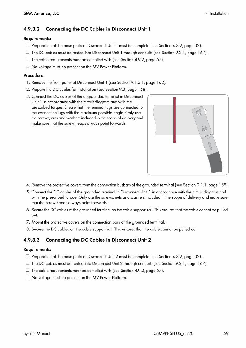
SMA America, LLC 4 Installation
System Manual CoMVPP-SH-US_en-20 59
4.9.3.2 Connecting the DC Cables in Disconnect Unit 1Requirements: Preparation of the base plate of Disconnect Unit 1 must be complete (see Section 4.3.2, page 32). The DC cables must be routed into Disconnect Unit 1 through conduits (see Section 9.2.1, page 167). The cable requirements must be complied with (see Section 4.9.2, page 57). No voltage must be present on the MV Power Platform.
Procedure:1. Remove the front panel of Disconnect Unit 1 (see Section 9.1.3.1, page 162).2. Prepare the DC cables for installation (see Section 9.3, page 168).3. Connect the DC cables of the ungrounded terminal in Disconnect
Unit 1 in accordance with the circuit diagram and with the prescribed torque. Ensure that the terminal lugs are connected to the connection lugs with the maximum possible angle. Only use the screws, nuts and washers included in the scope of delivery and make sure that the screw heads always point forwards.
4. Remove the protective covers from the connection busbars of the grounded terminal (see Section 9.1.1, page 159).5. Connect the DC cables of the grounded terminal in Disconnect Unit 1 in accordance with the circuit diagram and
with the prescribed torque. Only use the screws, nuts and washers included in the scope of delivery and make sure that the screw heads always point forwards.
6. Secure the DC cables of the grounded terminal on the cable support rail. This ensures that the cable cannot be pulled out.
7. Mount the protective covers on the connection bars of the grounded terminal.8. Secure the DC cables on the cable support rail. This ensures that the cable cannot be pulled out.
4.9.3.3 Connecting the DC Cables in Disconnect Unit 2Requirements: Preparation of the base plate of Disconnect Unit 2 must be complete (see Section 4.3.2, page 32). The DC cables must be routed into Disconnect Unit 2 through conduits (see Section 9.2.1, page 167). The cable requirements must be complied with (see Section 4.9.2, page 57). No voltage must be present on the MV Power Platform.

4 Installation SMA America, LLC
60 CoMVPP-SH-US_en-20 System Manual
Procedure:1. Remove the front panel of Disconnect Unit 2 (see Section 9.1.3.1, page 162).2. Prepare the DC cables for installation (see Section 9.3, page 168).3. Remove the protective covers from the connection busbars of the grounded terminal (see Section 9.1.1, page 159).4. Connect the DC cables of the grounded terminal in Disconnect Unit 2 in accordance with the circuit diagram and
with the prescribed torque. Only use the screws, nuts and washers included in the scope of delivery and make sure that the screw heads always point forwards.
5. Connect the DC cables of the ungrounded terminal in Disconnect Unit 2 in accordance with the circuit diagram and with the prescribed torque. Ensure that the terminal lugs are connected to the connection lugs with the maximum possible angle. Only use the screws, nuts and washers included in the scope of delivery and make sure that the screw heads always point forwards.
6. Secure the DC cables of the grounded terminal on the cable support rail. This ensures that the cable cannot be pulled out.
7. Mount the protective covers on the connection bars of the grounded terminal.
4.9.4 Connecting the DC Cables to the Sunny CentralIf the MV Power Platform is not equipped with Disconnect Units, connect the DC cables in the Sunny Central.
Figure 35: DC terminals in the Sunny Central
Position Positive grounding Negative grounding Without groundingA DC+ terminal DC– terminal DC– terminalB DC– terminal DC+ terminal DC+ terminal

SMA America, LLC 4 Installation
System Manual CoMVPP-SH-US_en-20 61
Requirements: Preparation of the Sunny Central base plate must be complete (see Section 4.3.2, page 32). The DC cables must be routed into Sunny Central through conduits (see Section 9.2.1, page 167). The cable requirements must be complied with (see Section 4.9.2, page 57). No voltage must be present on the MV Power Platform.
Procedure:1. Prepare the DC cables for installation (see Section 9.3, page 168).2. Remove the panels of the Sunny Central (see Section 9.1.2.1, page 161).3. Remove the protective covers from the connection busbars of the grounded terminal (see Section 9.1.1, page 159).4. Connect the DC cables with the specified torque in accordance with the circuit diagram. Only use the screws, nuts
and washers included in the scope of delivery and make sure that the screw heads always point forwards.5. Secure the DC cables on the cable support rail. This ensures that the cable cannot be pulled out.6. Mount the panels of the Sunny Central (see Section 9.1.2.2, page 161).
4.10 Final Installation Work4.10.1 Sealing the Base PlatesOnce installation work is completed, the base plates must be sealed. This protects the MV Power Platform from moisture.Additionally required mounting material (not included in the scope of delivery): Suitable material for sealing the base plates (e.g. expanding foam)
Procedure:• Seal the base plates of the MV Power Platform.
4.10.2 Mounting the PanelsWhen all installation work is complete, or if protracted interruptions are anticipated during installation, the panels on the devices must be closed.Procedure:
1. Mount the front panels on the Disconnect Units (see Section 9.1.3.2, page 164).2. If applicable, mount the panels of the inverters (see Section 9.1.2.2, page 161).

5 Disconnecting and Reconnecting SMA America, LLC
62 CoMVPP-SH-US_en-20 System Manual
5 Disconnecting and Reconnecting5.1 Safety When Disconnecting and Reconnecting
Danger to life from electric shock due to live voltageThere are high voltages present in the MV Power Platform and its components. Touching live components results in death or serious injury due to electric shock.
• When working in a high contact-risk environment, wear Hazard Risk Category 2 personal protective equipment.• Always perform work in compliance with the regulations specified in 29 CFR, Chapter XVII, Part 1910 (OSHA),
NEC, and NFPA 70E.• Do not touch live components.• Follow the instructions precisely.• Observe the safety warnings on the devices and in the documentation.• Ensure that no disconnected components can be reconnected.• After disconnecting the MV Power Platform, wait at least 15 minutes until the inverter capacitors have discharged
completely.• Before performing any work on the MV Power Platform, ensure that no voltage is present in any of the components.
Risk of burns due to hot devices or componentsSome devices or components on the MV Power Platform can reach high temperatures during operation. Touching these components can result in burn injuries.
• Observe the safety warnings on the devices and in the documentation.• During operation, do not touch any devices or components marked with such warnings.• After disconnecting the PV system, wait until any hot components or devices, e.g., the MV transformer, have cooled
down sufficiently.
Hazard Risk Category 2 protective equipment requiredIn accordance with NFPA 70E, an arc flash hazard risk analysis has been performed by SMA, and appropriate Arc Flash Hazard labels stating the required Personal Protective Equipment (PPE) for exposed, energized interaction with the equipment, are installed. Hazard Risk Category 2 PPE is the requirement for all routine maintenance, diagnostics, and commissioning activities as described in the SMA protocols. Areas within the machine also exist that cannot, under any circumstances, be exposed while energized. These areas are marked accordingly on the machine, and can only be made accessible after de-energization of the inverter.For additional information, please contact the SMA Service Line.
Authorization for switching the MV TransformerOnly a duly authorized person trained in electrical safety is allowed to connect or disconnect the AC voltage of the medium-voltage transformer. Use the load-break switch on the left-hand exterior panel of the MV transformer.
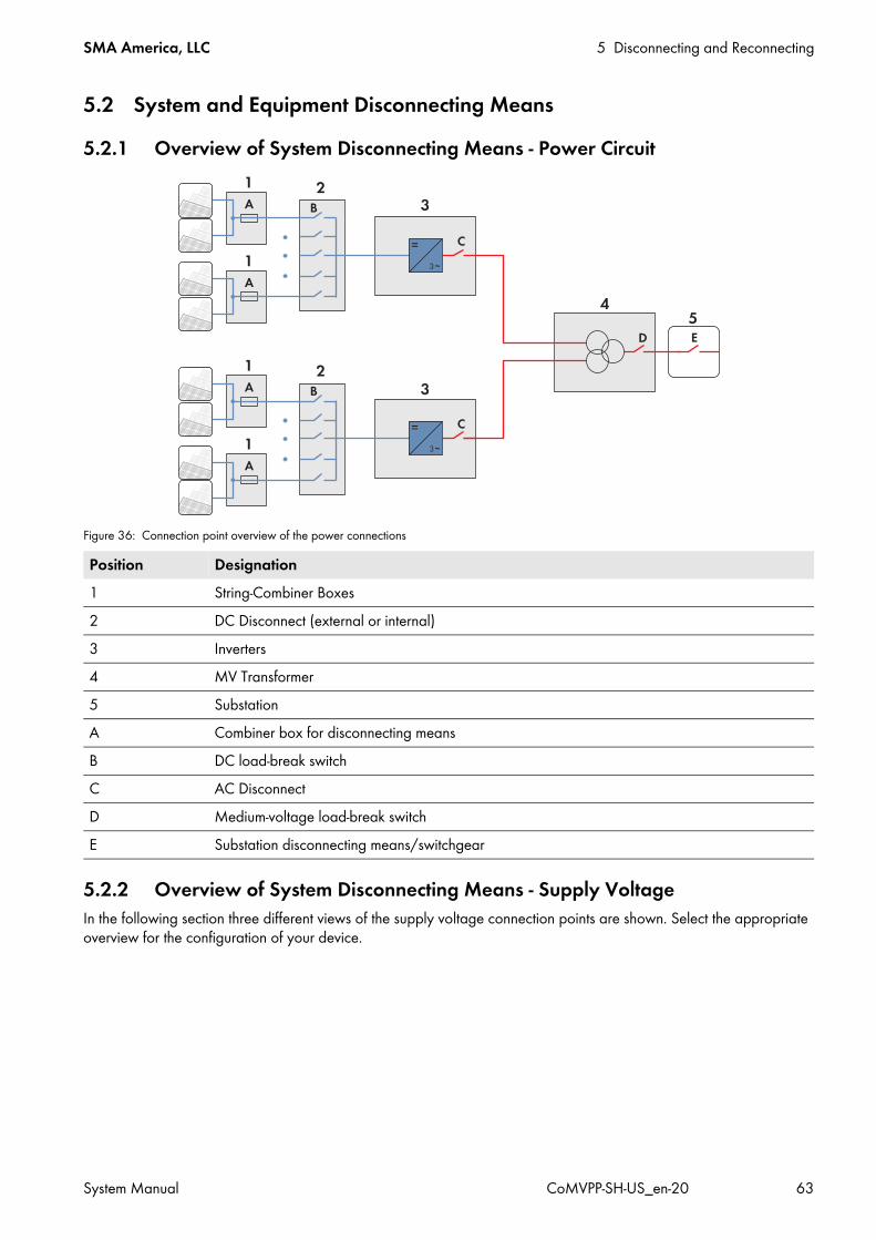
SMA America, LLC 5 Disconnecting and Reconnecting
System Manual CoMVPP-SH-US_en-20 63
5.2 System and Equipment Disconnecting Means5.2.1 Overview of System Disconnecting Means - Power Circuit
Figure 36: Connection point overview of the power connections
5.2.2 Overview of System Disconnecting Means - Supply VoltageIn the following section three different views of the supply voltage connection points are shown. Select the appropriate overview for the configuration of your device.
Position Designation1 String-Combiner Boxes2 DC Disconnect (external or internal)3 Inverters4 MV Transformer5 SubstationA Combiner box for disconnecting meansB DC load-break switchC AC DisconnectD Medium-voltage load-break switchE Substation disconnecting means/switchgear

5 Disconnecting and Reconnecting SMA America, LLC
64 CoMVPP-SH-US_en-20 System Manual
5.2.2.1 Internal Supply Voltage
Figure 37: Overview of the connection points for internal voltage supply via the Auxiliary Services Rack
5.2.2.2 External Supply Voltage
Figure 38: Overview of the connection points for external voltage supply via the Auxiliary Services Rack
Position Designation1 Main Box2 Tracker Box*
* Optional
A Main switch of the Main BoxB Main switch of the Tracker Box*
Position Designation1 Distribution*2 Brown Power Box3 Main Box4 Tracker Box**

SMA America, LLC 5 Disconnecting and Reconnecting
System Manual CoMVPP-SH-US_en-20 65
5.3 Disconnecting the Compact MV Power Platform5.3.1 Switching off the Inverters
1. Turn the key switches on the inverters to Stop.2. Remove the keys. It is recommended that the keys are kept in the possession of the technician.
5.3.2 Disconnecting the DC Side5.3.2.1 For Platforms with External DC Disconnects
Additionally required material: Five lockout devices. Diameter of the shackle: 0.2 in. to 0.3 in. (5 mm to 8 mm)
Requirement: The inverter is switched off(see Section 5.3.1, page 65).
Procedure:1. Operate the switch levers of the Disconnect Units:
• Switch all switch levers to the left to the OFF position.
5 Inverter Box**A Low-voltage distribution disconnecting meansB Main switch of the Brown Power BoxC Main switch of the Main BoxD Main switch of the Tracker Box**E Main switch of the Inverter Box**
* Not included in the scope of delivery** Optional
Position Designation

5 Disconnecting and Reconnecting SMA America, LLC
66 CoMVPP-SH-US_en-20 System Manual
• Pull the lock brackets out of the switch levers.
• Hook the lockout devices in the lock brackets and lock them. This will ensure that the switch levers cannot reconnect inadvertently.
2. Ensure that no voltage is present on the load side of the DC switches.3. Cover or shield any adjacent live components.
5.3.2.2 For Platforms with Internal DC Switch
Additionally required material: Two lockout devices. Diameter of the shackle: 0.2 in. to 0.3 in. (5 mm to 8 mm)
Requirement: The inverter is switched off(see Section 5.3.1, page 65).lockout device
Procedure:1. Operate the DC Switch on the front door of each inverter:
• Turn both switches to the OFF position. The red light repeater lights up.

SMA America, LLC 5 Disconnecting and Reconnecting
System Manual CoMVPP-SH-US_en-20 67
2. Secure the DC Switch on the inverter door against accidental reconnection using a lockout device.3. Wait 15 minutes until the Sunny Central capacitors have discharged completely.4. If necessary, disconnect the DC voltage in the combiner boxes, lock-out and tag-out.
5.3.3 Disconnecting the AC Side
It is recommended that remote disconnection be used whenever possible. Operate load-break switches using a hotstick. After the load-break switch is switched to the OPEN position, ensure that no voltage is present at the transformer secondary terminals and then ground the secondary terminals to prevent transformer backfeed energization.
Additionally required material: Three lockout devices. Diameter of the shackle: 0.2 in. to 0.3 in. (5 mm to 8 mm)
Requirement: The inverter is switched off(see Section 5.3.1, page 65).
Danger to life due to electric shock when live components are touched• Adhere to the disconnection procedure specified in the documentation of the medium-voltage switching device
(see medium-voltage switching device documentation).• Strictly follow all safety signs, labels or instructions present.• Do not operate load-break switches if a fault condition is suspected. Doing so can cause an explosion or fire.• Use a hotstick to operate the MV transformer load-break equipment. • After operating the load-break equipment of the MV transformer, check that voltages at the transformer terminals
are the expected values. Checking voltages verifies that load-break equipment is operated properly and that electrical circuit conditions are as expected.
• Before servicing transformer secondary connected equipment, ensure that no voltage is present at any of the transformer secondary terminals and ground the transformer secondary terminals in accordance with the locally applicable standards and guidelines. Grounding secondary terminals protects against situations such as a standby generator energizing an MV transformer from the secondary circuit.
• Before servicing the MV transformer, always disconnect the transformer from a remote upstream source and then proceed to ground all primary and secondary transformer terminals in accordance with the locally applicable standards and guidelines. Grounding secondary terminals protects against situations such as a standby generator energizing the transformer from the secondary circuit.
• Follow industry accepted safety practices. Utilize protective clothing and equipment when working with load-break equipment.
• Ground the outgoing feeder section.• Ensure that no voltage is present.
When switching at low temperatures, the two-position load-break switch may not work properly. Components that are supposedly disconnected, may be live.
• Three-phase padmounted transformers use R-Temp® or Envirotemp® FR3n for an transformer oil. When the transformer oil temperature is less than 0°C (32°F) for R-Temp or less than -10°C (14°F) for Envirotemp FR3, viscosity is reduced, which may reduce make and break capabilities of load-break devices. Below these temperatures, under-oil load-break accessories should not be used to make or break a load. Instead, disconnect the MV transformer from a remote upstream source before operating under-oil load-break switches.
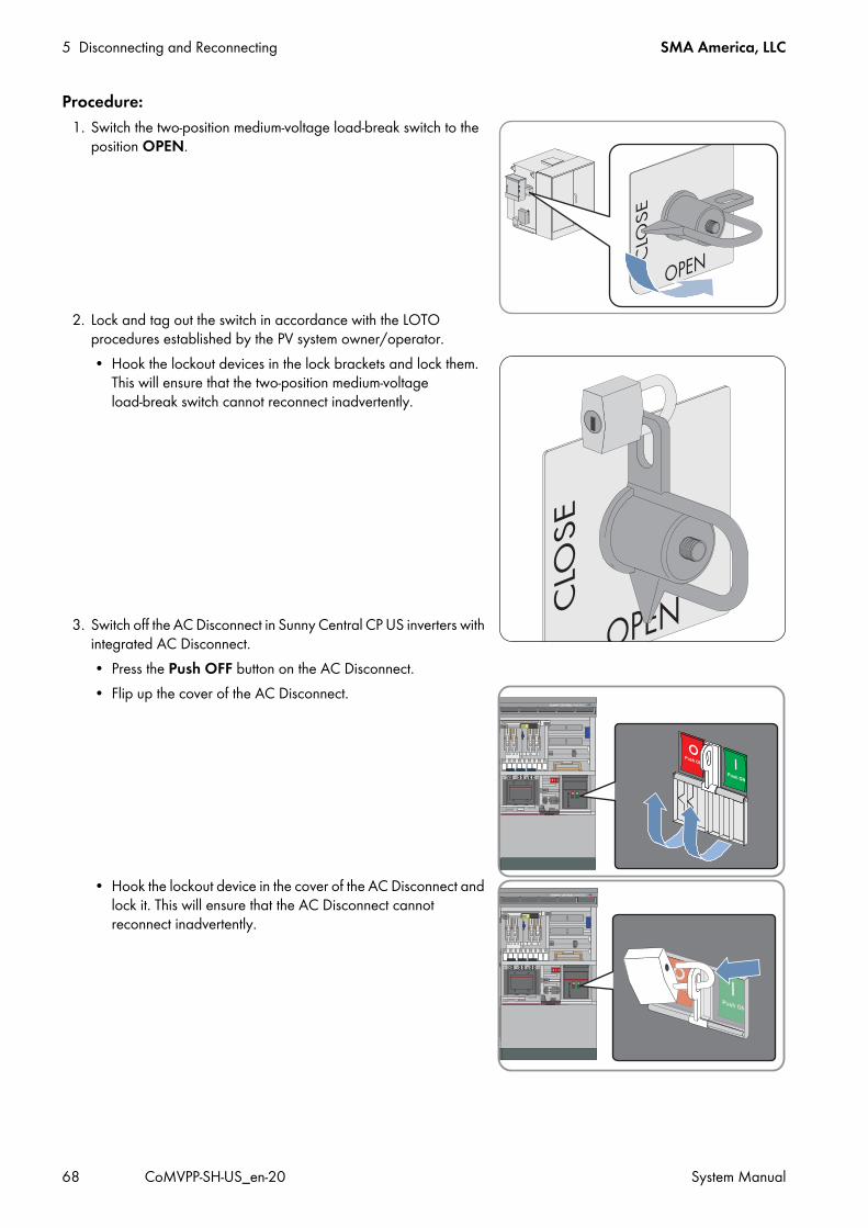
5 Disconnecting and Reconnecting SMA America, LLC
68 CoMVPP-SH-US_en-20 System Manual
Procedure:1. Switch the two-position medium-voltage load-break switch to the
position OPEN.
2. Lock and tag out the switch in accordance with the LOTO procedures established by the PV system owner/operator.• Hook the lockout devices in the lock brackets and lock them.
This will ensure that the two-position medium-voltage load-break switch cannot reconnect inadvertently.
3. Switch off the AC Disconnect in Sunny Central CP US inverters with integrated AC Disconnect.• Press the Push OFF button on the AC Disconnect. • Flip up the cover of the AC Disconnect.
• Hook the lockout device in the cover of the AC Disconnect and lock it. This will ensure that the AC Disconnect cannot reconnect inadvertently.

SMA America, LLC 5 Disconnecting and Reconnecting
System Manual CoMVPP-SH-US_en-20 69
5.3.4 Disconnecting the Supply Voltage Source5.3.4.1 For Platforms Configured for Internal Supply
Figure 39: Connection points on the Auxiliary Services Rack
Additionally required material: If the Auxiliary Services Rack is used, four lockout devices are required. Diameter of the shackle: 0.2 in. to 0.3 in.
(5 mm to 8 mm)Requirement: The inverter is switched off(see Section 5.3.1, page 65).
Position DesignationA Tracker Box*
* Optional
B Main Box
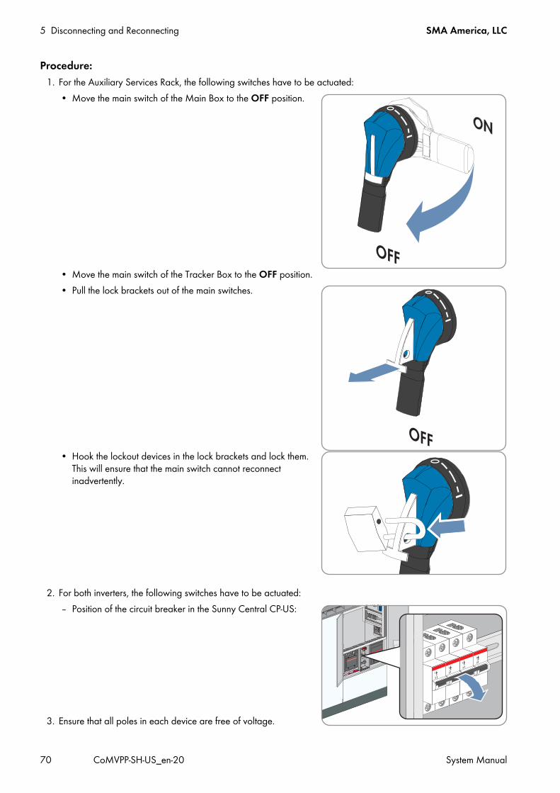
5 Disconnecting and Reconnecting SMA America, LLC
70 CoMVPP-SH-US_en-20 System Manual
Procedure:1. For the Auxiliary Services Rack, the following switches have to be actuated:
• Move the main switch of the Main Box to the OFF position.
• Move the main switch of the Tracker Box to the OFF position.• Pull the lock brackets out of the main switches.
• Hook the lockout devices in the lock brackets and lock them. This will ensure that the main switch cannot reconnect inadvertently.
2. For both inverters, the following switches have to be actuated:– Position of the circuit breaker in the Sunny Central CP-US:
3. Ensure that all poles in each device are free of voltage.
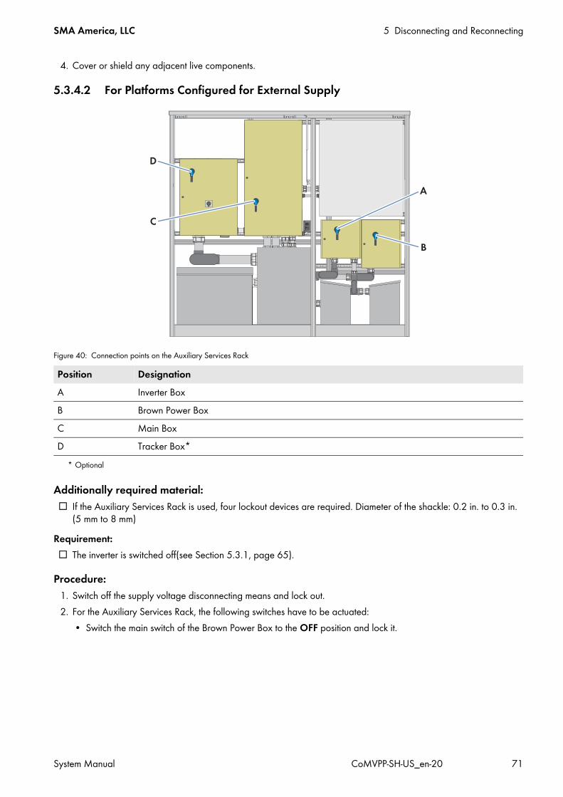
SMA America, LLC 5 Disconnecting and Reconnecting
System Manual CoMVPP-SH-US_en-20 71
4. Cover or shield any adjacent live components.
5.3.4.2 For Platforms Configured for External Supply
Figure 40: Connection points on the Auxiliary Services Rack
Additionally required material: If the Auxiliary Services Rack is used, four lockout devices are required. Diameter of the shackle: 0.2 in. to 0.3 in.
(5 mm to 8 mm)Requirement: The inverter is switched off(see Section 5.3.1, page 65).
Procedure:1. Switch off the supply voltage disconnecting means and lock out.2. For the Auxiliary Services Rack, the following switches have to be actuated:
• Switch the main switch of the Brown Power Box to the OFF position and lock it.
Position DesignationA Inverter BoxB Brown Power BoxC Main BoxD Tracker Box*
* Optional

5 Disconnecting and Reconnecting SMA America, LLC
72 CoMVPP-SH-US_en-20 System Manual
5.4 Reconnecting the MV Power Platform5.4.1 Reconnecting the Supply Voltage Source5.4.1.1 For Platforms Configured for Internal Supply
1. Switch on the circuit breakers of the supply voltage in the inverters.2. For the Auxiliary Services Rack, all switches have to be actuated:
• Unlock the lockout devices and remove them from the lock brackets.• Push the lock brackets towards the main switch. The lock brackets must line up with the main switches.• Move the main switch of the Main Box to the ON position.• If a Tracker Box is connected, switch the main switch of the Tracker Box to the ON position.
5.4.1.2 For Platforms Configured for External Supply1. If no Auxiliary Services Rack is used, switch on the circuit breakers of the supply voltage in the inverters.2. In addition, all switches have to be actuated for the Auxiliary Services Rack:
• Unlock the lockout devices and remove them from the lock brackets.• Push the lock brackets towards the main switch. The lock brackets must line up with the main switches.• In case of external supply voltage, switch the main switch of the Brown Power Box to the ON position.
3. Switch on the external supply voltage disconnecting means.

SMA America, LLC 5 Disconnecting and Reconnecting
System Manual CoMVPP-SH-US_en-20 73
5.4.2 Reconnecting the AC Source
It is recommended that remote disconnection be used whenever possible. Operate load-break switches using a hotstick. After the load-break switch is switched to the OPEN position, ensure that no voltage is present at the transformer secondary terminals and then ground the secondary terminals to prevent transformer backfeed energization.
Procedure:1. Switch on the AC Disconnect in Sunny Central CP-US inverters with integrated AC Disconnect.
• Open the lockout device and remove it. • Flip down the cover.• Press the Push ON button.
2. Unlock the lockout devices and remove them from the two-position medium-voltage load-break switch.3. Switch the two-position medium-voltage load-break switch to position CLOSE.
Danger to life due to electric shock when live components are touched• Adhere to the disconnection procedure specified in the documentation of the medium-voltage switching device
(see medium-voltage switching device documentation).• Strictly follow all safety signs, labels or instructions present.• Do not operate load-break switches if a fault condition is suspected. Doing so can cause an explosion or fire.• Use a hotstick to operate the MV transformer load-break equipment. • After operating the load-break equipment of the MV transformer, check that voltages at the transformer terminals
are the expected values. Checking voltages verifies that load-break equipment is operated properly and that electrical circuit conditions are as expected.
• Before servicing transformer secondary connected equipment, ensure that no voltage is present at any of the transformer secondary terminals and ground the transformer secondary terminals in accordance with the locally applicable standards and guidelines. Grounding secondary terminals protects against situations such as a standby generator energizing an MV transformer from the secondary circuit.
• Before servicing the MV transformer, always disconnect the transformer from a remote upstream source and then proceed to ground all primary and secondary transformer terminals in accordance with the locally applicable standards and guidelines. Grounding secondary terminals protects against situations such as a standby generator energizing the transformer from the secondary circuit.
• Follow industry accepted safety practices. Utilize protective clothing and equipment when working with load-break equipment.
• Ground the outgoing feeder section.• Ensure that no voltage is present.
When switching at low temperatures, the two-position load-break switch does not work properly. Components that are supposedly disconnected, may be live.
• Three-phase padmounted transformers use R-Temp® or Envirotemp® FR3n for an transformer oil. When the transformer oil temperature is less than 0°C (32°F) for R-Temp or less than -10°C (14°F) for Envirotemp FR3, viscosity is reduced, which may reduce make and break capabilities of load-break devices. Below these temperatures, under-oil load-break accessories should not be used to make or break a load. Instead, de-energize the transformer from a remote upstream source before operating under-oil load-break devices.
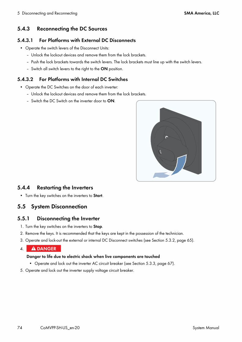
5 Disconnecting and Reconnecting SMA America, LLC
74 CoMVPP-SH-US_en-20 System Manual
5.4.3 Reconnecting the DC Sources5.4.3.1 For Platforms with External DC Disconnects
• Operate the switch levers of the Disconnect Units:– Unlock the lockout devices and remove them from the lock brackets.– Push the lock brackets towards the switch levers. The lock brackets must line up with the switch levers.– Switch all switch levers to the right to the ON position.
5.4.3.2 For Platforms with Internal DC Switches• Operate the DC Switches on the door of each inverter:
– Unlock the lockout devices and remove them from the lock brackets.– Switch the DC Switch on the inverter door to ON.
5.4.4 Restarting the Inverters• Turn the key switches on the inverters to Start.
5.5 System Disconnection5.5.1 Disconnecting the Inverter
1. Turn the key switches on the inverters to Stop.2. Remove the keys. It is recommended that the keys are kept in the possession of the technician.3. Operate and lock-out the external or internal DC Disconnect switches (see Section 5.3.2, page 65).
5. Operate and lock out the inverter supply voltage circuit breaker.
4.Danger to life due to electric shock when live components are touched
• Operate and lock out the inverter AC circuit breaker (see Section 5.3.3, page 67).

SMA America, LLC 5 Disconnecting and Reconnecting
System Manual CoMVPP-SH-US_en-20 75
– Position of the circuit breaker in the Sunny Central CP-US:
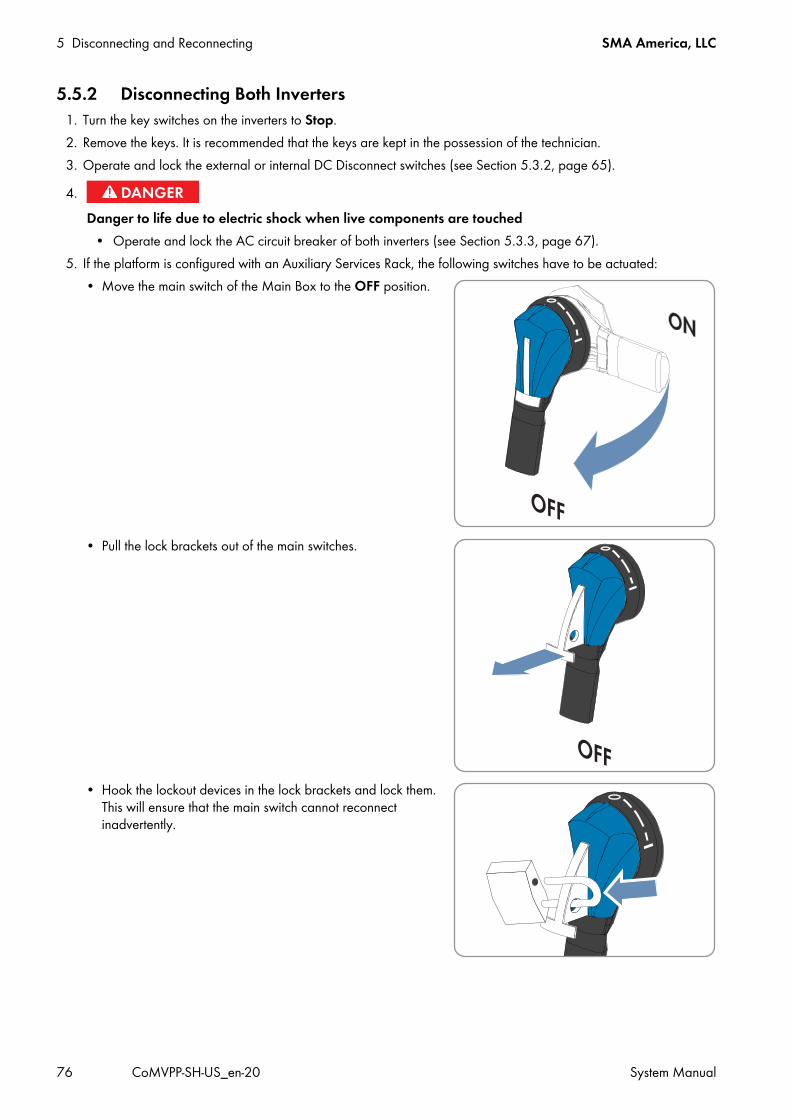
5 Disconnecting and Reconnecting SMA America, LLC
76 CoMVPP-SH-US_en-20 System Manual
5.5.2 Disconnecting Both Inverters1. Turn the key switches on the inverters to Stop.2. Remove the keys. It is recommended that the keys are kept in the possession of the technician.3. Operate and lock the external or internal DC Disconnect switches (see Section 5.3.2, page 65).
5. If the platform is configured with an Auxiliary Services Rack, the following switches have to be actuated:• Move the main switch of the Main Box to the OFF position.
• Pull the lock brackets out of the main switches.
• Hook the lockout devices in the lock brackets and lock them. This will ensure that the main switch cannot reconnect inadvertently.
4.Danger to life due to electric shock when live components are touched
• Operate and lock the AC circuit breaker of both inverters (see Section 5.3.3, page 67).
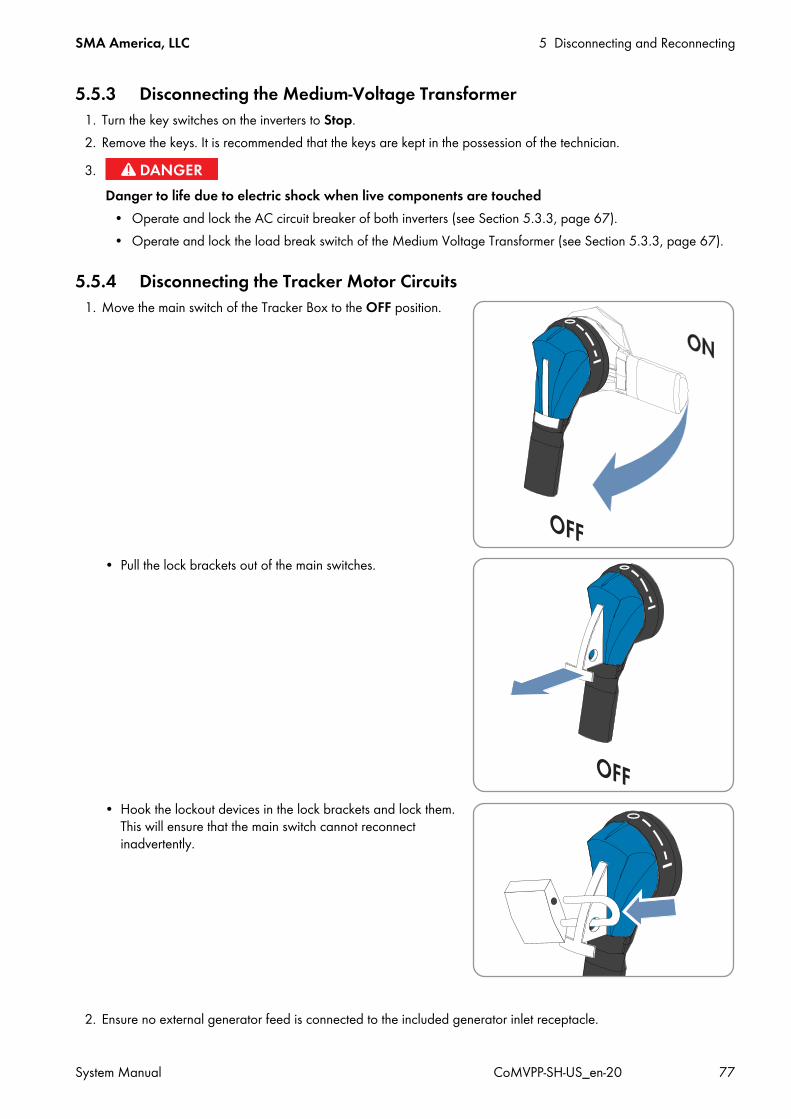
SMA America, LLC 5 Disconnecting and Reconnecting
System Manual CoMVPP-SH-US_en-20 77
5.5.3 Disconnecting the Medium-Voltage Transformer1. Turn the key switches on the inverters to Stop.2. Remove the keys. It is recommended that the keys are kept in the possession of the technician.
5.5.4 Disconnecting the Tracker Motor Circuits1. Move the main switch of the Tracker Box to the OFF position.
• Pull the lock brackets out of the main switches.
• Hook the lockout devices in the lock brackets and lock them. This will ensure that the main switch cannot reconnect inadvertently.
2. Ensure no external generator feed is connected to the included generator inlet receptacle.
3.Danger to life due to electric shock when live components are touched
• Operate and lock the AC circuit breaker of both inverters (see Section 5.3.3, page 67).• Operate and lock the load break switch of the Medium Voltage Transformer (see Section 5.3.3, page 67).

5 Disconnecting and Reconnecting SMA America, LLC
78 CoMVPP-SH-US_en-20 System Manual
5.5.5 Disconnecting the 120V Auxiliary Circuits of the PlatformDisconnect the voltage supply for the customized Box and the outlets for the main switch of the Main Box.
1. Move the main switch of the Main Box to the OFF position.
• Pull the lock brackets out of the main switches.
• Hook the lockout devices in the lock brackets and lock them. This will ensure that the main switch cannot reconnect inadvertently.
SMA America, LLC 6 Operation
System Manual CoMVPP-SH-US_en-20 79
6 OperationThis section describes the main operating elements of the devices of the MV Power Platform such as the switches, the touch display and the user interface. It also describes how to configure the system and network settings, how to switch the insulation monitoring and which parameters are important for the safe operation of the inverter. This section has no mandatory sequence of actions.
6.1 System Settings via Touch Display6.1.1 Selecting the Language
1. Select .2. Select .3. Select the language based on the country symbols.4. Confirm entry by selecting .
6.1.2 Setting the Date, Time and Time Zone
1. Select .2. Select .3. To change the date, select the day, month and year in the field. Use the and buttons to change the day,
month and year.4. To change the time, select the hour, minute and second one after another in the field. Use and to change
the hours, minutes and seconds.5. To change the time zone, select a time zone in the field . Use the and buttons to change the time zone.
6.1.3 Selecting the Display Format of the Touch Display1. Select .2. Select .3. Select the date format.4. Select the hour format.5. Select the number format.6. Confirm entry by selecting .
6.1.4 Setting the Brightness of the Touch Display1. Select .2. Select .3. Set the display brightness. Select for a darker screen or for a lighter screen.4. Confirm entry by selecting .
SC-COM accepts changesThe SC-COM will accept date, time or time zone changes made on the display.

6 Operation SMA America, LLC
80 CoMVPP-SH-US_en-20 System Manual
6.2 Changing the System Settings via the User Interface6.2.1 Setting the LanguageYou can also set the language of the user interface via the XML file custom.xml (see Section 6.2.6, page 81).Procedure:
1. Log into the user interface (see Section 9.5.1, page 173).2. Select Sunny Central > Settings > System.3. Select the desired language in the Language field.4. Select [Save].5. To log off from the user interface, select [Logout].
6.2.2 Setting the Date, Time and Time Zone1. Log into the user interface (see Section 9.5.1, page 173).2. Select Sunny Central > Settings > System.3. Select [Change] in the Time zone (UTC offset) field.4. Select the correct time zone in the Time zone (UTC offset) drop-down list.5. Select an option in the Automatic change from summer time to winter time field:
6. Enter the current date in the New date field.7. Enter the current time in the New time field.8. Select [Save].9. To log off from the user interface, select [Logout].
6.2.3 Entering the Operator Name1. Log into the user interface (see Section 9.5.1, page 173).2. Select Sunny Central > Settings > System.3. Enter the operator name in the Operator name field.4. Select [Save].5. To log off from the user interface, select [Logout].
Option Explanationyes Automatic change from daylight saving time to standard time is active.no Automatic change from daylight saving time to standard time is not active. Date and time have to be
set manually.

SMA America, LLC 6 Operation
System Manual CoMVPP-SH-US_en-20 81
6.2.4 Resetting the SC-COMResetting the SC-COM will restore all of its original default settings. If you have uploaded an XML file custom.xml, the settings of this file are copied (see Section 6.2.6, page 81).
Procedure:1. Log into the user interface as an installer (see Section 9.5.1, page 173).2. Select Sunny Central > Info.3. Select [Default setting].
A window containing a security question opens.4. Select [Confirm].5. To log off from the user interface, select [Logout].
6.2.5 Changing the Password for the User GroupsThe SC-COM differentiates between the user groups "user" and "installer" (for information on user rights, see Section 12.3, page 271). To change the password for the "installer" user group, you must be logged in as an installer. To change the password for the "user" user group, you can be logged in as a user or an installer.
While you enter your password, the user interface displays information on the security level of the password entered. The SC-COM categorizes passwords as very unsafe, unsafe, adequate, safe and very safe. Only select passwords with a security quality level that is at least safe.You can also change the password of the "installer" user group via the XML file custom.xml (see Section 6.2.6, page 81).Procedure:
1. Log into the user interface (see Section 9.5.1, page 173).2. Select Sunny Central > Settings > Security.3. Enter a secure password in the User password or Installer password fields and confirm it in the second field.4. Select [Save].5. To log off from the user interface, select [Logout].
6.2.6 Customized Settings via XML FileThis section describes how to configure the system and network settings using an XML file custom.xml. To enable the settings, the SC-COM must be reset to the default settings. This action is optional. Most settings can also be configured via the user interface.
Backing up data• Before you reset the SC-COM, note down all settings such as network or portal settings.• To avoid data loss, be sure to back up your PV system data.
PV system identifier in Sunny PortalIf you reset the SC-COM settings, the SC-COM will delete all login settings for Sunny Portal. If you restart the SC-COM after reset without changing any settings, the SC-COM will create a new PV system profile with a new system identifier in Sunny Portal.
• If the SC-COM is configured to send data to the existing PV system in Sunny Portal, adjust the identifier of the existing PV system (see Section 6.4.3.2, page 91).
• Enter the e-mail address of a user who has Sunny Portal administrator rights for the PV system.
Identical passwords for the user groupsIf your "User" password is the same as your "Installer" password, you will automatically be logged in as an installer.
6 Operation SMA America, LLC
82 CoMVPP-SH-US_en-20 System Manual
6.2.6.1 Uploading the custom.xml FileIf you upload the custom.xml file to the user interface, the SC-COM checks the file to ensure that the values entered are valid and accurate, and copies the settings when the SC-COM is next reset.
Procedure:1. Create the custom.xml file with the required settings (see Section 6.2.7, page 83).2. Log into the user interface as an installer (see Section 9.5.1, page 173).3. Select Sunny Central > Settings > System.4. Select [Browse] in the Upload settings (custom.xml) field.5. Double-click on the custom.xml file in the open dialog box.6. Select [Upload].
The message "Do you really want to copy the customer-specific settings?" is displayed. The message "The settings were not copied as the file has an invalid format or invalid entries." is displayed?
• Click on the symbol.• Read off the error in the open dialog box and correct the custom.xml file.• Ensure that the custom.xml file is valid and correct.
7. Select [Confirm]. The message "The settings were successfully saved" is displayed. The settings will become effective by carrying
out a reset to default settings." 8. To enable the settings in the custom.xml file, reset the SC-COM to the default settings (see Section 6.2.4, page 81).9. To log off from the user interface, select [Logout].
6.2.6.2 Downloading the XML File custom.xmlThe file custom.xml that you uploaded can also be downloaded.Procedure:
1. Log into the user interface as an installer (see Section 9.5.1, page 173).2. Select Sunny Central > Settings > System.3. Click on the custom.xml link in the Upload settings (custom.xml) field.4. Choose a storage location for the file and save it.5. To log off from the user interface, select [Logout].
Correct network settingsWhile uploading, the SC-COM checks the XML file custom.xml for validity and accuracy of the entered values. It is not checked whether the settings for the network are correct.
• Ensure that the custom.xml file includes the correct network settings.

SMA America, LLC 6 Operation
System Manual CoMVPP-SH-US_en-20 83
6.2.6.3 Deleting the custom.xml FileYou can delete the custom.xml file via the user interface. If you have made your personal settings effective via the custom.xml file before deleting it, these settings remain effective.
Procedure:1. Log into the user interface as an installer (see Section 9.5.1, page 173).2. Select Sunny Central > Settings > System.3. In the Upload settings (custom.xml) field, select the [Delete] button.
The custom.xml file is immediately deleted.4. To log off from the user interface, select [Logout].
6.2.7 XML File for Customer-Specific Settings6.2.7.1 Structure of the XML File custom.xmlSo that the SC-COM can correctly read the settings from the XML file, the file has to be written correctly.
No confirmation after deleting the custom.xml fileIf you perform the following steps, the SC-COM deletes the custom.xml file immediately without displaying the dialog window for confirmation.
• Save the custom.xml file before you delete the file.
Elements of the XML file Explanation<?xml version="1.0" encoding="utf-8" standalone="yes" ?>
Required element of the XML file
<WebBox xmlns:msdata="urn:schemas-microsoft-com:xml-msdata" xmlns:xsi="http://www.w3.org/2001/XMLSchema-instance" xsi:noNamespaceSchemaLocation="config_100.xsd">
Required element of the XML fileIs finished with the tag </WebBox> at the end of the XML file
<Info> <Version>my config V1.01</Version> </Info>
Required element of the XML file You have to enter the name and the version for your settings between the version tags. This information is displayed in the header of the user interface.
<Config> <Key>NetworkSettings_DhcpUsage1</Key> <Value>False</Value> </Config>
Here, you can set the parameters and your values (see Section 6.2.7.2, page 84).
<Loader> <Settings> <PowerFail>2500</PowerFail> </Settings> </Loader>
You can set the period in ms that determines the shut-down time of the SC-COM after the SC-COM has received the signal of the inverter's uninterruptible power supply about the failure of the voltage supply.The value must be greater than or equal to 2,500. This setting is immediately adopted after the file is uploaded.
6 Operation SMA America, LLC
84 CoMVPP-SH-US_en-20 System Manual
6.2.7.2 Parameters and Values for the custom.xml File
Example: XML file for setting the English language of the user interface<?xml version="1.0" encoding="utf-8" standalone="yes" ?> - <WebBox xmlns:msdata="urn:schemas-microsoft-com:xml-msdata" xmlns:xsi="http://www.w3.org/2001/XMLSchema-instance" xsi:noNamespaceSchemaLocation="config_100.xsd">-<Info> <Version>my config V1.01</Version> </Info> <Config> <Key>NativeSettings_Language</Key> <Value>en</Value> </Config> </WebBox>
Parameter Explanation Values Default values
NetworkSettings_DhcpUsage1 Activates the DHCP for LAN2. The True value ignores all other settings of the IP addresses for LAN2.
True FalseFalse
NetworkSettings_DnsIpAddr1 Sets the first IPv4 address of the DNS server for LAN2
‒ ‒0.0.0.0
A valid IPv4 addressNetworkSettings_Dns2IpAddr1 Sets the second IPv4 address of the
DNS server for LAN2.‒ 0.0.0.0
0.0.0.0A valid IPv4 address
NetworkSettings_Gateway1 Sets the gateway address for LAN2 0.0.0.0 0.0.0.0NetworkSettings_IpAddr1 Sets the IPv4 address for LAN2 A valid IPv4 address 172.24.1.51NetworkSettings_SubnetMask1 Sets the subnet mask for the LAN2 255.255.0.0 255.255.0.0NetworkSettings_DhcpUsage2 Activates the DHCP for LAN3. The True
value ignores all other settings of the IP addresses for LAN3.
True FalseFalse
NetworkSettings_DnsIpAddr2 Sets the first IPv4 address of the DNS server for LAN3
‒ ‒0.0.0.0
A valid IPv4 addressNetworkSettings_Dns2IpAddr2 Sets the second IPv4 address of the
DNS server for LAN3‒ 0.0.0.0
0.0.0.0A valid IPv4 address
NetworkSettings_Gateway2 Sets the gateway address for LAN3 0.0.0.0 0.0.0.0NetworkSettings_IpAddr2 Sets the IPv4 address for LAN3 A valid IPv4 address 172.16.1.51NetworkSettings_SubnetMask2 Sets the subnet mask for the LAN3 255.255.0.0 255.255.0.0
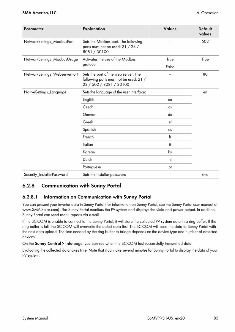
SMA America, LLC 6 Operation
System Manual CoMVPP-SH-US_en-20 85
6.2.8 Communication with Sunny Portal6.2.8.1 Information on Communication with Sunny PortalYou can present your inverter data in Sunny Portal (for information on Sunny Portal, see the Sunny Portal user manual at www.SMA-Solar.com). The Sunny Portal monitors the PV system and displays the yield and power output. In addition, Sunny Portal can send useful reports via e-mail.If the SC-COM is unable to connect to the Sunny Portal, it will store the collected PV system data in a ring buffer. If the ring buffer is full, the SC-COM will overwrite the oldest data first. The SC-COM will send the data to Sunny Portal with the next data upload. The time needed by the ring buffer to bridge depends on the device type and number of detected devices.On the Sunny Central > Info page, you can see when the SC-COM last successfully transmitted data.Evaluating the collected data takes time. Note that it can take several minutes for Sunny Portal to display the data of your PV system.
NetworkSettings_ModbusPort Sets the Modbus port. The following ports must not be used: 21 / 23 / 8081 / 30100
‒ 502
NetworkSettings_ModbusUsage Activates the use of the Modbus protocol
True TrueFalse
NetworkSettings_WebserverPort Sets the port of the web server. The following ports must not be used: 21 / 23 / 502 / 8081 / 30100
‒ 80
NativeSettings_Language Sets the language of the user interface: enEnglish enCzech cs German deGreek el Spanish es French fr Italian it Korean koDutch nl Portuguese pt
Security_InstallerPassword Sets the installer password ‒ sma
Parameter Explanation Values Default values

6 Operation SMA America, LLC
86 CoMVPP-SH-US_en-20 System Manual
6.2.8.2 Accessing the SC-COM via Sunny PortalUsing Sunny Portal, you can access the SC-COM via the Internet.Every time the SC-COM connects with Sunny Portal, Sunny Portal saves the current address of the SC-COM or your router with which the Internet connection is established. If your router is configured accordingly, you can access your SC-COM via Sunny Portal.The last IP address that the SC-COM used to connect to Sunny Portal will be updated by the SC-COM during each data transmission. You can view this IP address in Sunny Portal by selecting Device Overview > Device Properties.If your network is permanently connected to the Internet, your Internet provider may interrupt the connection at regular intervals. This usually happens every 24 hours. When you establish a new Internet connection, your Internet provider will assign a new IP address to your network. The SC-COM will use the new IP address to connect to Sunny Portal. The IP address displayed by SC-COM is always up-to-date.
6.2.9 User Rights and Data Security6.2.9.1 User GroupsThe SC-COM distinguishes between the "user" and "installer" user groups. The distinction is made via different passwords. If the password is the same for both user groups, you will be logged in as installer.To prevent two users from making changes at the same time, only one user can ever be logged into the SC-COM at a time.
Accessing the SC-COM via Sunny Portal after a Change of IP AddressWhen your Internet provider assigns a new IP address to your network, Sunny Portal will not be able to access the SC-COM immediately. Before it can be accessed, the SC-COM must first send its new IP address to the Sunny Portal. The SC-COM transmits the IP address of the network every time data is transmitted.
The Router Must Forward Data Requests to the SC-COMTo access the SC-COM via the Sunny Portal, your router must be configured to forward all data requests from Sunny Portal to the SC-COM.
• If you are unable to access the SC-COM, make sure the router settings are correct.
User group RightsUser • Configure the system settings of the SC-COM, such as date and time
• Configure all network settings of the SC-COM except for the network port setting• Read out the instantaneous values and parameter settings• Change the password for the "user" user group
Installer • All rights of the "user" user group• Set the inverter parameters• Restore the default settings of the SC-COM• Delete the device description• Delete the Sunny Portal buffer• Change passwords for both user groups

SMA America, LLC 6 Operation
System Manual CoMVPP-SH-US_en-20 87
6.2.9.2 Strength of PasswordsTo improve the strength of your password, note the following points when selecting a password:
• Use passwords with a minimum length of eight characters. The longer the password, the more secure it is.• Do not use names or common words (e.g. dog, cat or house).• Do not use data related to your person as passwords (for example names of persons or pets, personal numbers or
identification numbers, car license plates).• Do not repeat names or words (e.g. househouse, catcat).• Use a combination of upper and lower case letters, special characters and numbers.• Do not use number and letter combinations which are consecutive on a keyboard (for example "12345", "qwert").
6.2.9.3 Increasing Data SecurityThe inverter can be connected to the Internet. Note that connecting to the Internet carries the risk that unauthorized users can gain access to and manipulate your data.
• Change the password after your first login.• Make sure you use a high-strength password (see Section 6.2.9.2, page 87).• Change your passwords at regular intervals (see Section 6.2.9.2, page 87).• Protect your password from access by unauthorized users.• Never leave slips of paper with passwords lying around.• Set up a firewall.• Close unnecessary network ports.
6.3 Network SettingsThis section describes how to configure the network settings for your PV system. You must choose between a static or dynamic network and adjust the network ports if necessary.
6.3.1 Configuring the Network Settings on the ComputerBefore you can change the network settings, you must configure the computer to the network settings of the inverter.
Procedure:1. Note down the IP address of the computer.2. Adapt the IP address of the computer to the address range of the inverter.
Administrator rights in the operating systemFor commissioning, you need to have the appropriate administrator rights to change the computer network settings.
• For questions about administrator rights, contact your network administrator.
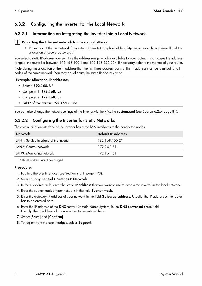
6 Operation SMA America, LLC
88 CoMVPP-SH-US_en-20 System Manual
6.3.2 Configuring the Inverter for the Local Network6.3.2.1 Information on Integrating the Inverter into a Local Network
You select a static IP address yourself. Use the address range which is available to your router. In most cases the address range of the router lies between 192.168.100.1 and 192.168.255.254. If necessary, refer to the manual of your router.Note during the allocation of the IP address that the first three address parts of the IP address must be identical for all nodes of the same network. You may not allocate the same IP address twice.
You can also change the network settings of the inverter via the XML file custom.xml (see Section 6.2.6, page 81).
6.3.2.2 Configuring the Inverter for Static NetworksThe communication interface of the inverter has three LAN interfaces to the connected nodes.
Procedure:1. Log into the user interface (see Section 9.5.1, page 173).2. Select Sunny Central > Settings > Network.3. In the IP address field, enter the static IP address that you want to use to access the inverter in the local network.4. Enter the subnet mask of your network in the field Subnet mask.5. Enter the gateway IP address of your network in the field Gateway address. Usually, the IP address of the router
has to be entered here.6. Enter the IP address of the DNS server (Domain Name System) in the DNS server address field.
Usually, the IP address of the router has to be entered here.7. Select [Save] and [Confirm].8. To log off from the user interface, select [Logout].
Protecting the Ethernet network from external attacks• Protect your Ethernet network from external threats through suitable safety measures such as a firewall and the
allocation of secure passwords.
Example: Allocating IP addresses• Router: 192.168.1.1• Computer 1: 192.168.1.2• Computer 2: 192.168.1.3• LAN2 of the inverter: 192.168.1.168
Network Default IP addressLAN1: Service interface of the inverter 192.168.100.2*
* This IP address cannot be changed.
LAN2: Control network 172.24.1.51.LAN3: Monitoring network 172.16.1.51.
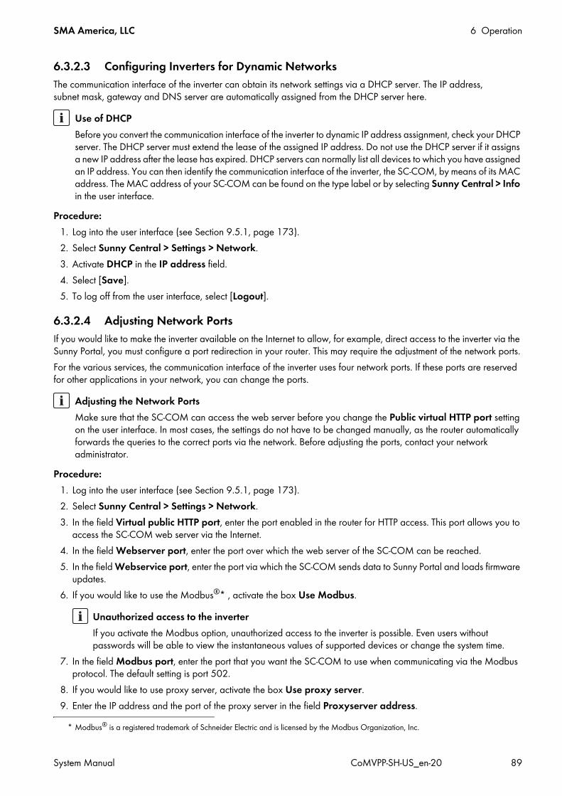
SMA America, LLC 6 Operation
System Manual CoMVPP-SH-US_en-20 89
6.3.2.3 Configuring Inverters for Dynamic NetworksThe communication interface of the inverter can obtain its network settings via a DHCP server. The IP address, subnet mask, gateway and DNS server are automatically assigned from the DHCP server here.
Procedure:1. Log into the user interface (see Section 9.5.1, page 173).2. Select Sunny Central > Settings > Network.3. Activate DHCP in the IP address field.4. Select [Save].5. To log off from the user interface, select [Logout].
6.3.2.4 Adjusting Network PortsIf you would like to make the inverter available on the Internet to allow, for example, direct access to the inverter via the Sunny Portal, you must configure a port redirection in your router. This may require the adjustment of the network ports.For the various services, the communication interface of the inverter uses four network ports. If these ports are reserved for other applications in your network, you can change the ports.
Procedure:1. Log into the user interface (see Section 9.5.1, page 173).2. Select Sunny Central > Settings > Network.3. In the field Virtual public HTTP port, enter the port enabled in the router for HTTP access. This port allows you to
access the SC-COM web server via the Internet.4. In the field Webserver port, enter the port over which the web server of the SC-COM can be reached.5. In the field Webservice port, enter the port via which the SC-COM sends data to Sunny Portal and loads firmware
updates.6. If you would like to use the Modbus®* , activate the box Use Modbus.
7. In the field Modbus port, enter the port that you want the SC-COM to use when communicating via the Modbus protocol. The default setting is port 502.
8. If you would like to use proxy server, activate the box Use proxy server.9. Enter the IP address and the port of the proxy server in the field Proxyserver address.
Use of DHCPBefore you convert the communication interface of the inverter to dynamic IP address assignment, check your DHCP server. The DHCP server must extend the lease of the assigned IP address. Do not use the DHCP server if it assigns a new IP address after the lease has expired. DHCP servers can normally list all devices to which you have assigned an IP address. You can then identify the communication interface of the inverter, the SC-COM, by means of its MAC address. The MAC address of your SC-COM can be found on the type label or by selecting Sunny Central > Info in the user interface.
Adjusting the Network PortsMake sure that the SC-COM can access the web server before you change the Public virtual HTTP port setting on the user interface. In most cases, the settings do not have to be changed manually, as the router automatically forwards the queries to the correct ports via the network. Before adjusting the ports, contact your network administrator.
* Modbus® is a registered trademark of Schneider Electric and is licensed by the Modbus Organization, Inc.
Unauthorized access to the inverterIf you activate the Modbus option, unauthorized access to the inverter is possible. Even users without passwords will be able to view the instantaneous values of supported devices or change the system time.
6 Operation SMA America, LLC
90 CoMVPP-SH-US_en-20 System Manual
10. If you would like to use the authentication of the proxy server, activate the box Use authentication.11. Enter the data of your proxy server in the fields User name and Password.12. Select [Save].13. To log off from the user interface, select [Logout].
6.4 Displaying Operating DataYou can call up the operating data on the touch display, on the user interface or in Sunny Portal. Depending on requirements, select how the operating data should be visualized.
6.4.1 Displaying the Operating Data on the Touch DisplayOn the touch display of the inverter, you can view the inverter data, the instantaneous values of the DC and AC side, the fed-in energy as well as the data on active and reactive power. You can access this operating data by selecting certain symbols on the touch display (see Section 10.4.2.1, page 186).
6.4.2 Displaying the Operating Data via the User Interface1. Log into the user interface (see Section 9.5.1, page 173).2. Select Data > Devices.3. Select .
A list of existing device types appears.4. Select the desired device type.
A list appears containing all existing devices of this type.5. Select the desired device from the list.6. Select the tab Spot values.
The list of operating data is displayed.7. To log off from the user interface, select [Logout].
6.4.3 Displaying the Operation Data via Sunny Portal6.4.3.1 Registering the Inverter in Sunny Portal
Procedure:1. Log into the user interface (see Section 9.5.1, page 173).2. Select Sunny Central > Settings > Data transmission.3. Enter the name of your PV system in the PV system name field. The name you enter will be displayed as the
PV system name in Sunny Portal.4. Set the data transmission frequency (see Section 6.5.2, page 92).5. Select yes in the field Use Sunny Portal.6. If you are already registered in Sunny Portal with the same PV system, update the PV system identifier in the
PV system identifier field (see Section 6.4.3.2, page 91).
Automatic PV system identifierSunny Portal uses this number to uniquely identify the PV system. In general, you do not have to change the preset number in the field PV system identifier field. If you have not yet registered in Sunny Portal, the SC-COM will automatically enter the preset PV system identifier in Sunny Portal after the first successful data upload. Sunny Portal will send the login data to the e-mail address you entered in the Operator e-mail field. You are now registered in Sunny Portal.
SMA America, LLC 6 Operation
System Manual CoMVPP-SH-US_en-20 91
7. Enter your e-mail address in the Operator e-mail field. Sunny Portal then sends your access data to the e-mail address entered.
8. Select [Save].9. Select Sunny Central > Info.
10. Select [Register] in the field Last Sunny Portal registration. The Sunny Portal password will be sent to the entered e-mail address.
11. To log off from the user interface, select [Logout].
6.4.3.2 Adjusting the PV System Identifier for Sunny PortalSunny Portal identifies the inverter via the PV system identifier. In the following cases, you must adjust the PV system identifier on the user interface.
• Data has already been sent to Sunny Portal via another communication device.• The set PV system identifier was reset.• The SC-COM was replaced by a different SC-COM.
Procedure:1. Log into Sunny Portal (www.SunnyPortal.com).2. Select Configuration > PV System Properties.3. Copy the PV system identifier to the clipboard.4. Log into the user interface (see Section 9.5.1, page 173).5. Select Sunny Central > Settings > Data transmission.6. Delete the content of the PV system identifier field.7. Paste the PV system identifier from the clipboard into the field PV system identifier.8. Select [Save].9. To log off from the user interface, select [Logout].
6.4.3.3 Deleting the Sunny Portal BufferYou can delete the data on the internal ring buffer.Procedure:
1. Log into the user interface as an installer (see Section 9.5.1, page 173).2. Select Sunny Central > Info.3. Select [Delete] in the field Sunny Portal buffer load.4. To log off from the user interface, select [Logout].
6.4.4 Displaying the Event ReportThe event report keeps a log of various SC-COM events, e.g. errors and warnings. The SC-COM can display the last 500 events of the report.Procedure:
1. Log into the user interface (see Section 9.5.1, page 173).2. Select Sunny Central > Events.
The event report is displayed.3. To log off from the user interface, select [Logout].
6 Operation SMA America, LLC
92 CoMVPP-SH-US_en-20 System Manual
6.5 Saving the Operating DataThis Section describes various methods for downloading and saving operating data. You must select the desired method.
6.5.1 Increasing Storage Capacity by AveragingThe communication interface of the inverter can form an average value using the data from a specified time frame. In this way, the data of the connected devices can be compressed and occupy less memory space in the SC-COM.Procedure:
1. Log into the user interface (see Section 9.5.1, page 173).2. Select Sunny Central > Recording.3. In the Averaging over field, select the time period for which the SC-COM is to calculate the average.4. Select [Save].5. To log off from the user interface, select [Logout].
6.5.2 Setting the Data Transmission FrequencyThe communication interface of the inverter can send the data to the Sunny Portal or to an external FTP server. You can specify how often and in what interval data will be sent by the SC-COM. All data upload settings are related to both data upload to the Sunny Portal as well as to data upload to an external FTP server.If the data transmission to the Sunny Portal or external FTP server fails, the SC-COM will make further attempts to transmit the data.Procedure:
1. Log into the user interface (see Section 9.5.1, page 173).2. Select Sunny Central > Settings > Data transmission.3. Select the upload frequency and time window in the field Upload frequency per time window.4. Select the maximum number of upload attempts in each time window in the field Maximum number of upload
attempts per time window.5. Select [Save].6. To log off from the user interface, select [Logout].
SMA America, LLC 6 Operation
System Manual CoMVPP-SH-US_en-20 93
6.5.3 Downloading Operating Data Using the FTP Server6.5.3.1 Defining Read and Write Access Rights for the FTP ServerThe communication interface of the inverter has an integrated FTP server. You can use the FTP server to access the data on the SC-COM. The data is available for view and download in CSV or XML format (see Section 6.5.4, page 94). In order to use the FTP server, you must first assign the respective read and write access rights for the FTP server on the user interface.Procedure:
1. Log into the user interface (see Section 9.5.1, page 173).2. Select Sunny Central > Settings > Security.3. Select an option in the field FTP server:
4. Select [Save].5. To log off from the user interface, select [Logout].
6.5.3.2 Accessing the FTP Server via the Internet BrowserYou can log into the FTP server of the SC-COM as either "user" or "installer".
Procedure:1. Start your Internet browser.2. Enter the FTP address of the SC-COM with your user name and password as:
ftp://[user name]:[password]@[IP address]
3. Press the enter key. A list of files on the FTP server is displayed.
Option ExplanationRead/write You have read and write access rights on the integrated FTP server.Read only You only have read access rights on the integrated FTP server.off The integrated FTP server is deactivated.
Stored user name and password in the Internet browserAfter you access the FTP server with an Internet browser, user name and passwords can remain saved in the Internet browser cache.
• Clear the Internet browser cache to prevent unauthorized access to the FTP server.
Example: Entering the FTP addressIf you want to log into the SC-COM with IP address 192.168.100.2 and your user name is "user" and password "1234", the correct FTP address is ftp://user:[email protected]

6 Operation SMA America, LLC
94 CoMVPP-SH-US_en-20 System Manual
6.5.3.3 Sending Data via FTP PushThe communication interface of the inverter has an FTP push function. With this function, the inverter can upload the data collected from your PV system to a local FTP server as an XML file (for information on installing a local FTP server and testing the FTP push function, see the Technical Information "Setting Up the FTP Push Function" at www.SMA-Solar.com).This section describes how to set and test the FTP push function.
Setting and Testing the FTP Push Function1. Log into the user interface (see Section 9.5.1, page 173).2. Select Sunny Central > Settings > Data transmission.3. Select yes in the Use FTP-Push service field.4. Enter the URL and port of the FTP server in the field FTP server.5. In the field Upload directory field, specify the desired folder on the FTP server in which the data is to be saved.6. Select an option in the field Use authentication:
7. Enter the data of your FTP server in the fields User name and Password.8. Set the data transmission frequency (see Section 6.5.2, page 92).9. To test the FTP push function, select the [Test] button in the field Test FTP connection.
Test file is sent to the FTP server. Test file is not sent to the FTP server?
• Ensure that the address of the FTP server and the upload directory are correct.• Repeat the FTP connection test.• If an error occurs, contact your network administrator.
10. Select [Save].11. To log off from the user interface, select [Logout].
6.5.4 Downloading Operating Data via HTTPYou can download the operating data collected via HTTP download. This function makes it possible to manually download your collected PV system data in CSV or XML format to your computer. You have to select the desired format.
6.5.4.1 Downloading Data in XML Format1. Log into the user interface (see Section 9.5.1, page 173).2. Select Sunny Central > Recording.3. Select XML in the Format field.4. Select the required month in the field Download. The data for the prior twelve months is available for download
via the user interface.5. Select [Download].6. Choose the save location.7. Select [Save].8. To log off from the user interface, select [Logout].
Option Explanationyes Authentication is needed for the FTP server. Continue with step 7.no Authentication is not required. Continue with step 8.
SMA America, LLC 6 Operation
System Manual CoMVPP-SH-US_en-20 95
6.5.4.2 Downloading Data in CSV FormatData saved in CSV format can be automatically imported into tables (e.g. in Microsoft Excel). The data is structured based on the separator and end of line characters that you specify.Procedure:
1. Log into the user interface (see Section 9.5.1, page 173).2. Select Sunny Central > Recording.3. Select the option CSV in the field Format.4. Select [Configure].5. Select the desired format of the file name in the field Filename format.6. Select an option in the field Create column headers:
7. Select an option in the field End-of-line character.
8. In the field Separator character, select the character you want to use to separate content in the CSV file. Tip: If you want to import CSV data into Microsoft Excel for evaluation, choose Comma as the separator.
9. In the field Number format, select the desired number format. Tip: If you want to import CSV data into Microsoft Excel for evaluation, select #.## as the number format.
10. In the field Timestamp format, select the desired time format.11. Select an option in the field Format of the status channels:
12. Select [Save].13. Select the required month in the field Download. The data for the prior twelve months is available for download
via the user interface.14. Select [Download].15. Select [Save].16. Choose the save location.17. Select [Save].18. To log off from the user interface, select [Logout].
Option Explanationyes A header is added to the CSV file.no No header is added to the CSV file.
Option ExplanationCRLF (Windows) Control character for Windows that is used to separate lines in a CSV file.LF (Unix/Linux) Control character for Linux that is used to separate lines in a CSV file.CR (Mac) Control character for Macintosh that is used to separate lines in a CSV file.
Option ExplanationNumeric Status information on the inverter is displayed in numeric format.Plain text Status information on the inverter is displayed as text.
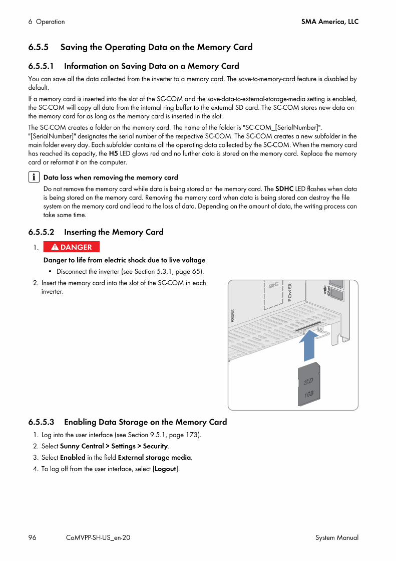
6 Operation SMA America, LLC
96 CoMVPP-SH-US_en-20 System Manual
6.5.5 Saving the Operating Data on the Memory Card6.5.5.1 Information on Saving Data on a Memory CardYou can save all the data collected from the inverter to a memory card. The save-to-memory-card feature is disabled by default.If a memory card is inserted into the slot of the SC-COM and the save-data-to-external-storage-media setting is enabled, the SC-COM will copy all data from the internal ring buffer to the external SD card. The SC-COM stores new data on the memory card for as long as the memory card is inserted in the slot.The SC-COM creates a folder on the memory card. The name of the folder is "SC-COM_[SerialNumber]". "[SerialNumber]" designates the serial number of the respective SC-COM. The SC-COM creates a new subfolder in the main folder every day. Each subfolder contains all the operating data collected by the SC-COM. When the memory card has reached its capacity, the H5 LED glows red and no further data is stored on the memory card. Replace the memory card or reformat it on the computer.
6.5.5.2 Inserting the Memory Card
2. Insert the memory card into the slot of the SC-COM in each inverter.
6.5.5.3 Enabling Data Storage on the Memory Card1. Log into the user interface (see Section 9.5.1, page 173).2. Select Sunny Central > Settings > Security.3. Select Enabled in the field External storage media.4. To log off from the user interface, select [Logout].
Data loss when removing the memory cardDo not remove the memory card while data is being stored on the memory card. The SDHC LED flashes when data is being stored on the memory card. Removing the memory card when data is being stored can destroy the file system on the memory card and lead to the loss of data. Depending on the amount of data, the writing process can take some time.
1.Danger to life from electric shock due to live voltage
• Disconnect the inverter (see Section 5.3.1, page 65).
SMA America, LLC 6 Operation
System Manual CoMVPP-SH-US_en-20 97
6.5.5.4 Displaying the Memory Capacity Available on the Memory Card1. Log into the user interface (see Section 9.5.1, page 173).2. Select Sunny Central > Info.3. The field SD card memory capacity field shows how much memory space is available on the memory card.4. To log off from the user interface, select [Logout].
6.6 Setting the ParametersIn the following section, all parameters that are relevant for the safe operation of the inverter and the MV Power Platform are specified. Only change the parameters that are relevant for your project.
6.6.1 Grid Management Services6.6.1.1 Setting the Power Frequency-Dependent Active Power Limitation Information on how power frequency-dependent active power limitation works can be found in Section 10.8.2, page 208. Information on default values and on the value range can be found in Section 10.11.1, page 234.Procedure:
1. Call up the parameter overview (see Section 9.5.3, page 173).2. Set the parameter P-HzStr.3. Set the parameter P-HzStop.4. Set the parameter P-WGra.5. Save the parameter change (see Section 9.5.4, page 173).
6.6.1.2 Setting the Active Power Limitation Independent of the FrequencyThere are five different procedures for power frequency-independent active power limitation. Information on the procedure can be found in Section 10.8.3, page 209. Information on default values and on the value range can be found in Section 10.11.1, page 234.
Procedure:1. Make sure the inverter is in the operating state "Stop".2. Call up the parameter overview (see Section 9.5.3, page 173).3. Select the procedure for power frequency-dependent active power limitation via the parameter P-WMod.4. If the WCnst procedure was selected, set the parameter P-W.5. If the WCnstNom procedure was selected, set the parameter P-WNom.6. Save the parameter change (see Section 9.5.4, page 173).
Parameter blockingThe parameter P-WMod may only be changed in the operating state "Stop". The entry will not be accepted in other operating states.

6 Operation SMA America, LLC
98 CoMVPP-SH-US_en-20 System Manual
6.6.1.3 Setting the Reactive Power ControlThere are eleven different procedures for reactive power regulation. Information on the procedure can be found in Section 10.8.4, page 210. Information on default values and on the value range can be found in Section 10.11.1, page 234.If a displacement power factor cos φ of 1 is to be maintained permanently, SMA recommends using the PFCnst procedure.
Procedure:1. Make sure the inverter is in the operating state "Stop".2. Call up the parameter overview (see Section 9.5.3, page 173).3. Select the procedure for active power limitation independent of the power frequency via the parameter Q-VArMod.4. If the VArCnst procedure was selected, set the parameter Q-VAr via the field Value.5. If the VArCnstNom procedure was selected, set the parameter Q-VArNom.6. If the PFCnst procedure was selected, set the parameters PF-PF and PF-PFExt.7. If the PFCnstAnIn procedure was selected, set the parameter PFAbsMin.8. If the PFCtlW procedure was selected, set the following parameters:
• Set the parameter PF-PFStr.• Set the parameter PF-PFExtStr.• Set the parameter PF-PFStop.• Set the parameter PF-PFExtStop.• Set the parameter PF-WStr.• Set the parameter PF-WStop.
9. If the VArCtlVol procedure was selected, set the following parameters:• Set the parameter Q-VDif.• Set the parameter Q-VArGra. • Set the parameter Q-VDifTm.• Set the parameter Q-VRtgOfsNom.
10. If the VArCtlVolHystDb procedure was selected, set the following parameters:• Set the parameter Q-VolWidNom.• Set the parameter Q-VolNomP1.• Set the parameter Q-VolNomP2.• Set the parameter Q-VArGraNom.• Set the parameter Q-VArTmsSpnt.• Set the parameter Q-VArTmsVtg.• Set the parameter Q-EnaTmsVtg.
11. Save the parameter change (see Section 9.5.4, page 173).
6.6.1.4 Setting “Q at Night”Information on the procedure can be found in Section 10.8.5, page 220
Parameter blockingThe parameter Q-VARMod may only be changed in the "Stop" operating state. The entry will not be accepted in other operating states.
SMA America, LLC 6 Operation
System Manual CoMVPP-SH-US_en-20 99
6.6.1.5 Setting Full and Limited Dynamic Grid Support (FRT)Information on full and limited dynamic grid support can be found in Section 10.8.7, page 228. Information on default values and on the value range can be found in Section 10.11.3, page 248.
Procedure:1. Call up the parameter overview (see Section 9.5.3, page 173).2. Set the parameter FRTEna.3. Set the parameter FRTArGraNom.4. Save the parameter change (see Section 9.5.4, page 173).
6.6.2 Grid Monitoring6.6.2.1 Setting the Line Voltage MonitoringInformation on how grid monitoring works in relation to the line voltage can be found in Section 10.7, page 204. Information on default values and on the value range can be found in Section 10.11.2, page 245.
Procedure:1. Call up the parameter overview (see Section 9.5.3, page 173).2. Set the parameter VCtlhhLimTm.3. Set the parameter VCtlhLimTm.4. Set the parameter VCtlhhLim.5. Set the parameter VCtlhLim.6. Save the parameter change (see Section 9.5.4, page 173).
6.6.2.2 Setting Power Frequency MonitoringInformation on how grid monitoring works in relation to power frequency can be found in Section 10.7.3, page 206. Information on default values and on the value range can be found in Section 10.11.2, page 245.
Procedure:1. Call up the parameter overview (see Section 9.5.3, page 173).
Function limitationThe FRT function cannot be active at the same time as the Active Islanding Detection function.
UL listing for Sunny Central CP-USThe default limiting values for the line voltage and the power frequency are configured in accordance with IEEE 1547, as required for UL1741 certification. These parameters may only be changed by authorized personnel at the written direction of the utility. The inverter can be operated outside the IEEE 1547 limits when required by the utility without loss of UL certification.
• Do not make any changes to the default limiting values for the grid monitoring parameters unless directed by the utility (see Section 9.3.2, page 170).
UL listing for Sunny Central CP-USThe default limiting values for the line voltage and the power frequency are configured in accordance with IEEE 1547, as required for UL1741 certification. These parameters may only be changed by authorized personnel at the written direction of the utility. The inverter can be operated outside the IEEE 1547 limits when required by the utility without loss of UL certification.
• Do not make any changes to the default limiting values for the grid monitoring parameters unless directed by the utility (see Section 10.11.2, page 245).
6 Operation SMA America, LLC
100 CoMVPP-SH-US_en-20 System Manual
2. Set the parameter HzCtlMaxTm.3. Set the parameter HzCtlhhLimTm.4. Set the parameter HzCtlhLimTm.5. Set the parameter HzCtllhLimTm.6. Set the parameter HzCtlllhLimTm.7. Set the parameter HzCtlMinTm.8. Save the parameter change (see Section 9.5.4, page 173).
6.6.2.3 Setting the Active Power Ramp-UpDuring regular start-up of the inverter, you can set the feed-in power to ramp up using the parameter WGra. This means that the inverter gradually increases the percentage feed-in power per second using the set value.If you do not set this parameter, the inverter will reach its maximum feed-in power in 400 ms.Information on default values and on the value range can be found in Section 10.10.1, page 231.Procedure:
1. Call up the parameter overview (see Section 9.5.3, page 173).2. Set the parameter WGra.3. To activate active power ramp-up, set the parameter WGraEna to On.4. Save the parameter change (see Section 9.5.4, page 173).
6.6.2.4 Setting the Decoupling Protection RampInformation on the decoupling protection ramp can be found in Section 10.9.2, page 230. Information on default values and on the value range can be found in Section 10.10.1, page 231.
Procedure:1. Make sure the inverter is in the operating state "Stop".2. Call up the parameter overview (see Section 9.5.3, page 173).3. Set the parameter WGraReconEna to On.4. Save the parameter change (see Section 9.5.4, page 173).
6.6.3 Setting the Voltage on the MV Transformer6.6.3.1 Setting the Secondary VoltageInformation on default values and on the value range can be found in Section 10.11.3, page 248.Procedure:
1. Call up the parameter overview (see Section 9.5.3, page 173).2. Set the parameter TrfVolExlLo.3. Set the parameter VRtg.4. Save the parameter change (see Section 9.5.4, page 173).
Parameter blockingThe parameter WGraReconEna must only be changed if the operating state is "Stop". The entry will not be accepted in other operating states.

SMA America, LLC 6 Operation
System Manual CoMVPP-SH-US_en-20 101
6.6.3.2 Setting the Primary VoltageInformation on default values and on the value range can be found in Section 10.11.3, page 248.Procedure:
1. Call up the parameter overview (see Section 9.5.3, page 173).2. Set the parameter TrfVolExlHi.3. Save the parameter change (see Section 9.5.4, page 173).
6.6.4 Setting Optional Parameters6.6.4.1 Deactivating Transformer ProtectionA fully hermetic protector is connected to the inverter. This fully hermetic protector is integrated into the MV transformer. If an error occurs in the MV transformer, the inverter switches off immediately.To deactivate this function, the associated parameter must be disabled.Information on default values and on the value range can be found in Section 10.11.5, page 250.
Procedure:1. Make sure the inverter is in the operating state "Stop".2. Call up the parameter overview (see Section 9.5.3, page 173).3. Set the parameter ExlTrfErrEna to Off.4. Save the parameter change (see Section 9.5.4, page 173).
6.6.4.2 Setting the Active Islanding DetectionInformation on islanding detection can be found in Section 10.6.2.4, page 199. Information on default values and on the value range can be found in Section 10.11.3, page 248.
Procedure:1. Make sure the inverter is in the operating state "Stop".2. Call up the parameter overview (see Section 9.5.3, page 173).3. Set the parameter EnaAid to On.4. Save the parameter change (see Section 9.5.4, page 173).
Parameter blockingThis parameter ExlTrfErrEna may only be changed if the operating state is "Stop". The entry will not be accepted in other operating states.
Parameter blockingThe parameter EnaAid may only be changed if the operating state is "Stop". The entry will not be accepted in other operating states.The "Active Islanding Detection" function cannot be active at the same time as the FRT function.

6 Operation SMA America, LLC
102 CoMVPP-SH-US_en-20 System Manual
6.6.5 Project-Specific Parameters6.6.5.1 Setting the Country
Procedure:1. Make sure the inverter is in the operating state "Stop".2. Call up the parameter overview (see Section 9.5.3, page 173).3. Set the parameter CntrySet.4. Save the parameter change (see Section 9.5.4, page 173).
6.6.5.2 Activating Remote ShutdownIf you activate remote shutdown, the inverter can be switched off and shut down via an external signal. Information on how to make the signal connection can be found in Section 4.8.7, page 51 and in Section 4.8.8, page 52.Procedure:
1. Call up the parameter overview (see Section 9.5.3, page 173).2. To activate remote shutdown, set the parameter ExlStrStpEna to On.3. Save the parameter change (see Section 9.5.4, page 173).
6.7 Setting the Insulation Monitoring of the PV SystemThis Section describes how you switch the PV array from grounded operation to insulated operation and back. Switching can be of use for maintenance or service work on the PV array, e.g. cutting the grass You have to select the cable applicable to the insulation monitoring of your PV system.
6.7.1 Setting the Insulation Monitoring Device6.7.1.1 Switching between Main Menu and Standard Operation
• To switch from standard operation to the main menu, press the [MENU] button. You can enter various sub-menus from the main menu.
• To return to standard operation, press the [RESET] button.6.7.1.2 Selecting PV Modules UsedThere are various measurement profiles available for the insulation monitoring. Select the measurement profile that is suitable for your PV modules.
Procedure:1. Access Main Menu.2. Select the ISO ADVANCED menu and then select the Measure menu.3. Select the measurement profile that matches the PV modules 4. and confirm by pressing [ENTER].
Parameter blockingSome parameters may only be changed in the operating state "Stop". The entry will not be accepted in other operating states.
Module types Measurement profilePV modules with crystalline cells AMP3PV modules with thin-film PV cells AMP4Other PV modules AMP
SMA America, LLC 6 Operation
System Manual CoMVPP-SH-US_en-20 103
6.7.2 Setting the Insulation Monitoring of the PV System with GFDI and an Insulation Monitoring Device
6.7.2.1 Safety during Insulation Monitoring of the PV System with GFDI and an Insulation Monitoring Device
Ground fault monitoring with GFDI does not provide protection from injury.The option "GFDI and insulation monitoring device" allows you to manually switch the PV array from grounded operation to insulated operation. To ensure that there is no insulation error on the grounded terminal, an insulation measurement is carried out. After switching to insulated operation, the insulation monitoring device checks each terminal of the PV array for potential insulation errors.Switching to insulated operation is useful whenever you need to perform maintenance or service work on or near the PV array (e.g. cutting the grass) or check the status of the insulation at regular intervals. After the maintenance work, the PV system should be switched to grounded operation once again.
6.7.2.2 Switching to Insulated Operation1. Set the key switch on the inverter to Stop.2. Wait 15 minutes. This ensures that the capacitors are discharged.3. Open the inverter.4. Manually switch off the GFDI circuit breaker. 5. Close the inverter.6. Set the key switch on the inverter to Start.
The insulation monitoring device starts collecting data. If the parameter IsoErrIgn is set to On,the error 3504 - insulation failure ignored is displayed.
The displayed error 3504 does not disappear after 15 minutes?The insulation is defective.• Have the insulation checked and, if necessary, repaired by a qualified person. • Acknowledge the error (see Section 7.3, page 107).
7. After a few minutes, display the instantaneous value Riso on the user interface (see Section 6.4.2, page 90). The insulation resistance Riso is greater than 45 k Ω . It is safe to enter the PV system. The insulation resistance Riso is less than 45 k Ω ?
There is an insulation error and the PV system must not be entered.• Have the insulation checked and, if necessary, repaired by a qualified person.
Danger to life from electric shock due to live voltageThere are high voltages present in the MV Power Platform and its components. Touching live components results in death or serious injury due to electric shock.
• Disconnect the inverters (see Section 5.3.1, page 65).
6 Operation SMA America, LLC
104 CoMVPP-SH-US_en-20 System Manual
6.7.2.3 Switching to Grounded Operation1. Set the key switch on the inverter to Stop.2. Wait 15 minutes. This ensures that the capacitors are discharged.3. Open the inverter.4. Check the insulation resistance displayed at the insulation monitoring device. If the insulation resistance is less than
1 k Ω , an insulation error occurred while the device was in insulated operation. This error must be remedied. The inverter must not be switched on. If the insulation resistance is greater than 1 k Ω , no insulation error occurred while the device was in insulated operation.
5. Switch on the GFDI circuit breaker.6. Close the inverter.7. Set the key switch on the inverter to Start.
6.7.3 Setting the Insulation Monitoring of the PV System with Remote GFDI and an Insulation Monitoring Device
6.7.3.1 Information on Insulating PV Modules Equipped with Remote GFDI and Insulation Monitoring Device
Ground fault monitoring with remote GFDI does not provide protection from injury.The "Remote GFDI and insulation monitoring device" option allows for an automatic switching of the PV array from grounded operation to insulated operation. To ensure that there is no insulation error on the grounded terminal, an insulation measurement is carried out. After switching to insulated operation, the insulation monitoring device checks each terminal of the PV array for potential insulation errors.Switching to insulated operation is useful whenever you need to perform maintenance or service work on or near the PV array (e.g. cutting the grass) or check the status of the insulation at regular intervals. After the maintenance work, the PV system should be switched to grounded operation once again.
6.7.3.2 Switching to Insulated Operation• Set the parameter RemMntSvc to On (see Section 6.6 "Setting the Parameters", page 97).
The warning 3517 ‒ Isolated mode, isolation detection is displayed. After a waiting time of approximately 15 minutes has expired, the insulation monitoring is activated.
The error message 3501 ‒ Insulation Failure is displayed.The insulation is defective.• Have the insulation checked and, if necessary, repaired by a qualified person.• Acknowledge the disturbance (see Section 7.3, page 107).
6.7.3.3 Switching to Grounded OperationSwitching to grounded operation is only possible if no insulation errors have been detected.Procedure:
• Set the parameter RemMntSvc to Off (see Section 6.6 "Setting the Parameters", page 97).or
• After a ground fault:– Turn the key switch to Stop and then back to Start after two seconds.

SMA America, LLC 6 Operation
System Manual CoMVPP-SH-US_en-20 105
6.8 Integrating New Devices into the PV SystemThis section describes how you detect devices of your PV system and delete the device description. You have to carry out these actions for commissioning or recommissioning.
6.8.1 Detecting New DevicesAll the devices connected to the inverter can be detected at once. Devices will need to be redetected if you:
• Exchanged devices in your PV system.• Removed devices from your PV system.• Added devices to your PV system.• Deleted the device description.
Procedure:1. Log into the user interface (see Section 9.5.1, page 173).2. Select Data > Detection.3. In the field Total number of devices to be detected, enter the number of devices that communicate with the
inverter.4. Select [Start detection].
The SC-COM starts detecting all devices and displays its progress. Once all devices have been detected, the SC-COM displays "### Device detection finished ###".
5. Select [OK].6. To log off from the user interface, select [Logout].
6.8.2 Deleting Device DescriptionsWhenever you replace a device in your PV system, the descriptions of the existing devices need to be deleted so that SC-COM is able to detect new devices.Procedure:
1. Log into the user interface as an installer (see Section 9.5.1, page 173).2. Select Sunny Central > Info.3. Select [Erase unit description]4. To log off from the user interface, select [Logout].
6.9 Updating the Firmware6.9.1 Information on Updating the FirmwareThere are a number of ways to update the firmware of the SC-COM. When the SC-COM firmware is updated, all the settings and data will be saved.
Detection of a PV system may take several minutesDepending on the number of devices in your PV system, the detection process may vary in duration.
• If the SC-COM does not indicate any progress after three minutes, cancel the search.• Make sure the data cable of each device is properly connected and repeat the search.
No access to the user interfaceDuring the update, the SC-COM restarts and access to the user interface will be temporarily blocked.

6 Operation SMA America, LLC
106 CoMVPP-SH-US_en-20 System Manual
6.9.2 Enabling Automatic Firmware UpdatesIf the SC-COM has Sunny Portal access, you can select to have the firmware updated automatically. Every time data is transmitted to Sunny Portal, a check is carried out to determine whether a new firmware version is available. If a new firmware update is available, the firmware update is downloaded and installed at night between 1 a.m. and 4 a.m. The automatic firmware update function is disabled on delivery.Procedure:
1. Log into the user interface (see Section 9.5.1, page 173).2. Select Sunny Central > Settings > Data transmission.3. Select the Yes option in the field Automatic firmware update.4. Select [Save].5. To log off from the user interface, select [Logout].
6.9.3 Updating Firmware via the User Interface1. Log into the user interface (see Section 9.5.1, page 173).2. Select Sunny Central > Info.
The window System information opens. If a new firmware version is available, the new version is displayed in the field Firmware version.
3. If a new version is available, select the [Update] button in the field Firmware version. The SC-COM loads and installs the new firmware.
4. To log off from the user interface, select [Logout].
SMA America, LLC 7 Troubleshooting
System Manual CoMVPP-SH-US_en-20 107
7 TroubleshootingThis section describes how to read out error messages at the inverter and acknowledge them once the cause has been eliminated. A list of error messages can be found in Section 7.4 „Corrective Measures in Event of Disturbance“, page 108.
7.1 Safety during the Troubleshooting
7.2 Reading Error MessagesIf an error occurs, you can read the error message via the touch display on the inverter or the user interface.
7.2.1 Reading Error Messages via Touch DisplayIf an error occurs, the touch display on the inverter shows a warning symbol.Procedure:
• Select the warning symbol. The touch display lists the error number, delay time, error message and the necessary corrective measure to
eliminate the error.
7.2.2 Reading Error Messages via the User InterfaceYou can read error messages with a computer via the user interface.Procedure:
1. Log into the user interface (see Section 9.5.1, page 173).2. To display the error message, select the value ErrNo in the instantaneous value view.3. To display the error message, select the value ErrNo in the instantaneous value view.4. To display the corrective measure required to eliminate the error, select the value Dsc in the instantaneous value
view.
7.3 Acknowledging Error MessagesOnce the error has been remedied, you can acknowledge the error message using the key switch on the inverter or via the user interface.
7.3.1 Acknowledging the Error Messages via the Key Switch
Danger to life from electric shock due to high voltages in the inverterEven when an error has occurred, high voltages are present in the inverter. Touching live components results in death or serious injury due to electric shock.
• All activities described in this section must be carried out by qualified personnel only.• Observe all safety precautions when working on the inverter.• Wear Hazard Risk Category 2 personal protective equipment.• If you cannot remedy the error with the help of this document, contact the SMA Service Line.
Dealing with errorsError messages should only be acknowledged once the underlying causes have been eliminated.If the causes of the error have not been eliminated, the error will still be detected after acknowledgement and the error message will appear again.

7 Troubleshooting SMA America, LLC
108 CoMVPP-SH-US_en-20 System Manual
Procedure:1. If an insulation error has occurred, switch the insulation monitoring device back on.2. Turn the key switch to Stop and then back to Start after two seconds.
7.3.2 Acknowledging Error Messages via the User Interface
You can only acknowledge errors via the user interface after entering the installer password.Procedure:
1. If an insulation error has occurred, switch the insulation monitoring device back on.2. Log into the user interface (see Section 9.5.1, page 173).3. Select the parameter Ackn in the device displaying the error, and set it to Ackn.4. Acknowledge entry with [Save].
7.3.3 Displaying the Error Message Delay TimeCertain errors, such as grid error, cause the inverter to shut down. If this is the case, there is a time for which the inverter waits before restarting. This is referred to as the delay time of the error message (TmsRmg). The inverter will show the delay time on the touch display when the error is read out.Procedure:
1. Log into the user interface (see Section 9.5.1, page 173).2. Go to the Instantaneous values tab on the user interface.3. View the delay time via the TmsRmg channel.
7.4 Corrective Measures in Event of Disturbance7.4.1 Inverter Behavior in the Event of an ErrorIf a disturbance occurs during inverter operation, this may be a warning or error.Each disturbance has two levels that influence the display and system behavior. The inverter only behaves differently in the two levels with a few disturbances. The level changes from 1 to 2 if the disturbance occurs five times within two hours or occurs permanently for two hours.A warning does not affect inverter behavior. The cause of the warning must be established and remedied.If operation is interrupted during an error, the inverter switches to the operating state "Disturbance" and opens the DC switchgear and the AC contactor. The error, error number, error message and a symbol are displayed on the touch display (see Section 10.4.2, page 186).If the cause of the error is rectified and the error is no longer displayed, the error is deleted from the fault memory. To view previous errors after they have been deleted from the fault memory, an event and disturbance file is saved on the SD card. The time when an error occurred and the type of error are entered in the event and disturbance file. This file also contains entries of relevance to service.
Dealing with errorsError messages should only be acknowledged once the underlying causes have been eliminated.If the cause of the error has not been eliminated, the error will still be detected after acknowledgement and the error message will appear again.
SMA America, LLC 7 Troubleshooting
System Manual CoMVPP-SH-US_en-20 109
You will find the following information in the error tables in Section 7.4.2, 7.4.3 and 7.4.4:Information Level Behavior ExplanationError no. ‒ ‒ Clearly identifies the disturbance presentExplanation ‒ ‒ Identifies possible causes of the disturbanceInverter behavior Depends on the severity of the disturbance
Disturbance level S1, disturbance level S2
Warning (W) The inverter has issued a warning that has no impact on how the inverter behaves.
Time The inverter has detected an error and switches into the operating state "Disturbance". The DC switching connection and AC contactor opens and the inverter does not feed in for the specified time. The time indicates how long the error is displayed on the touch display and is saved in the inverter as an error. If the time has elapsed, the error is no longer shown on the touch display. The inverter then checks whether the cause of the error has been rectified. If the cause of the error still exists after the time has expired or the error has been acknowledged, the error occurs again and the inverter remains in the operating state "Disturbance".
Acknowledge (A) The inverter switches into the operating state "Disturbance", opens the DC switching direction and AC contactor and does not feed in electricity until the error has been manually acknowledged. When the error has been acknowledged, it is no longer shown on the touch display. The inverter then checks whether the cause of the error has been rectified. If the error is no longer present, it is deleted from the memory. If the cause of the error is still present after the error has been acknowledged, the error occurs again.

7 Troubleshooting SMA America, LLC
110 CoMVPP-SH-US_en-20 System Manual
Inverter behavior Disturbance level S1, disturbance level S2
Day change (D) The inverter switches into the operating state "Disturbance", opens the DC switching connection and AC contactor and does not feed in. The error message is automatically reset when the day changes. If the error has been reset, it is no longer shown on the touch display. The inverter then checks whether the cause of the error has been rectified. If the error is no longer present, it is deleted from the memory. If the cause of the error is still present after the day has changed or after the error has been acknowledged, the error occurs again.
Plant-spec. (C) The inverter switches into the operating state "Disturbance", opens the DC switching connection and AC contactor and does not feed in. How long the inverter remains in this state depends on the plant-specific influencing factors. If the time has elapsed, the error is no longer shown on the touch display. The inverter then checks whether the cause of the error has been rectified. If the error is no longer present, it is deleted from the memory.
Reset (R) ‒ The control is restarted. The relays are checked and the voltage supply of the control is switched off. This process requires less than one minute. When the control is started up, the inverter's regular waiting times for grid monitoring are maintained.
Corrective measures
‒ ‒ The corrective measures specify measures that can help you rectify the error.
Information Level Behavior Explanation

SMA America, LLC 7 Troubleshooting
System Manual CoMVPP-SH-US_en-20 111
7.4.2 Error Numbers 01xx to 13xx - Disturbance on the Utility GridAfter a grid failure, the inverter monitors the utility grid for a specific period until it is reconnected.If the inverter monitors the utility grid after a grid error, the grid monitoring time is maintained.Certain errors, such as grid errors, cause the Sunny Central to shut down. In this case, the instantaneous value TmsRmg indicates the time during which the inverter monitors the utility grid until it is reconnected. This grid monitoring time can be defined in parameter GdErrTm.Error no. Explanation Behavior of the
Sunny CentralCorrective measures
S 1 S 2 R0103*
* Depending on the parameterization, the error message must be acknowledged manually.
Line voltage is too high. Overvoltage detected by redundant monitoring.
30 s 30 s ‒ • Check the line voltage.• Check the grid connection.• Check whether the utility grid is
stable.• Make sure the external fuses
function properly.• Make sure the AC cable
connections are securely connected.
0104* Line voltage is too high. Overvoltage detected by standard monitoring.
C C ‒
0203* Line voltage is too low. Undervoltage detected by redundant monitoring.
30 s 30 s ‒
0204* The line voltage is too low. Undervoltage detected by standard monitoring.
30 s 30 s ‒
0205* A line conductor of the utility grid has failed.
30 s 30 s ‒
0502* Power frequencyis too low. Power frequency fault detected by standard monitoring.
30 s 30 s ‒ • Check power frequency.• Check the grid monitoring relay
display.• Make sure the fuses in the load
circuit function properly.0503* Power frequency is too high. Power
frequency fault detected by standard monitoring.
30 s 30 s ‒
0504* Power frequency is too low. Power frequency fault detected by redundant monitoring.
30 s 30 s ‒
0505* Power frequency is too high. Power frequency fault detected by redundant monitoring.
30 s 30 s ‒
0506* The Sunny Central has detected a stand-alone grid and disconnected from the utility grid.
W W ‒ • Check power frequency.
0801 A line conductor of the utility grid has failed.
30 s 30 s ‒ • Check the line voltage.• Make sure the external fuses
function properly.• Make sure the AC cable
connections are securely connected.
0802*
1301 Left rotating magnetic field is connected. 30 s Q ‒ • Check phase position.• Make sure all fuses are switched on.
1500* The conditions for grid reconnection are not achieved again after a grid error.
W W ‒ • Check power frequency and line voltage.
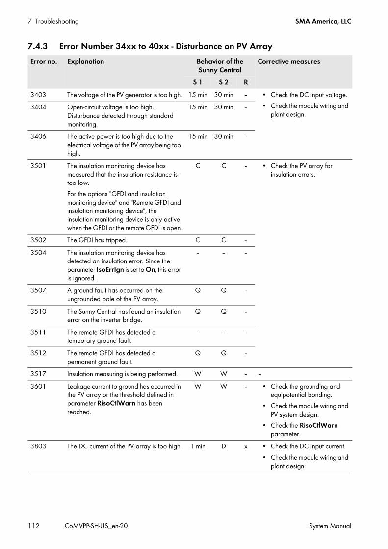
7 Troubleshooting SMA America, LLC
112 CoMVPP-SH-US_en-20 System Manual
7.4.3 Error Number 34xx to 40xx - Disturbance on PV ArrayError no. Explanation Behavior of the
Sunny CentralCorrective measures
S 1 S 2 R3403 The voltage of the PV generator is too high. 15 min 30 min ‒ • Check the DC input voltage.
• Check the module wiring and plant design.
3404 Open-circuit voltage is too high. Disturbance detected through standard monitoring.
15 min 30 min ‒
3406 The active power is too high due to the electrical voltage of the PV array being too high.
15 min 30 min ‒
3501 The insulation monitoring device has measured that the insulation resistance is too low.For the options "GFDI and insulation monitoring device" and "Remote GFDI and insulation monitoring device", the insulation monitoring device is only active when the GFDI or the remote GFDI is open.
C C ‒ • Check the PV array for insulation errors.
3502 The GFDI has tripped. C C ‒3504 The insulation monitoring device has
detected an insulation error. Since the parameter IsoErrIgn is set to On, this error is ignored.
‒ ‒ ‒
3507 A ground fault has occurred on the ungrounded pole of the PV array.
Q Q ‒
3510 The Sunny Central has found an insulation error on the inverter bridge.
Q Q ‒
3511 The remote GFDI has detected a temporary ground fault.
‒ ‒ ‒
3512 The remote GFDI has detected a permanent ground fault.
Q Q ‒
3517 Insulation measuring is being performed. W W ‒ ‒3601 Leakage current to ground has occurred in
the PV array or the threshold defined in parameter RisoCtlWarn has been reached.
W W ‒ • Check the grounding and equipotential bonding.
• Check the module wiring and PV system design.
• Check the RisoCtlWarn parameter.
3803 The DC current of the PV array is too high. 1 min D x • Check the DC input current.• Check the module wiring and
plant design.

SMA America, LLC 7 Troubleshooting
System Manual CoMVPP-SH-US_en-20 113
7.4.4 Error Numbers 60xx to 90xx - Disturbance on the Sunny Central
4003 Reverse currents detected in the PV array or DC connection polarity reversed.
30 s Q ‒ • Check PV modules for short circuits.
• Check the module wiring and plant design.
• Make sure the DC terminals have the correct polarity.
Error no. Explanation Behavior of the Sunny Central
Corrective measures
S 1 S 2 R6002 Calibration data cannot be loaded. ‒ ‒ ‒ • Contact the SMA Service Line.6113 Data block cannot be loaded from the
EEPROM or the channel list has changed (e.g. after a firmware update)
‒ ‒ ‒
6115 Hardware limiting values on the D/A converters cannot be set.
5 min 5 min x
6116 Real-time clock is not initialized. ‒ ‒ ‒6117 Device address not recognized. 5 min 5 min x6119 The data structure for the exchange
between the operation control unit and the digital signal processor is invalid.
5 min 5 min x
6120 Waiting for response from the OCU 30 s ‒ ‒6121 Waiting for response from the DSP 30 s ‒ ‒6122 Ten internal monitoring errors have
occurred in succession.‒ 5 min ‒
6128 General error 5 min 5 min ‒6404 Overcurrent on the L1, L2 or L3 line
conductors.30 s 5 min x
6405 Overvoltage in the DC link 30 s 5 min x6410 24 V voltage supply is invalid. 5 min 5 min x6417 15 V voltage supply is invalid. 5 min 5 min x6418 Overtemperature on the inverter bridge 5 min 15 min x6422 The inverter bridge is in an undefined state. 30 s 5 min x • Contact the SMA Service Line.6423 Overtemperature detected in the switch
cabinet 5 min 30 min x
6425 Synchronization error with the utility grid. 30 s 5 min x6427 Sensor error of the DC voltage
measurement.30 s C x
Error no. Explanation Behavior of the Sunny Central
Corrective measures
S 1 S 2 R

7 Troubleshooting SMA America, LLC
114 CoMVPP-SH-US_en-20 System Manual
6440 The MV transformer is no longer hermetically sealed.
30 s 5 min ‒ • Check MV transformer.
6441 Sensor error occurred during measurement of the DC voltage.
30 s 30 s ‒ • Contact the SMA Service Line.
6443 An unspecified error has occurred in the digital signal processor.
30 s ‒ ‒
6447 Self-test in the inverter bridge failed. Q Q ‒6448 Insulation monitoring delivers
non-permitted values.W W ‒ • Check insulation monitoring.
6451 Measured AC voltage from the Sunny Central is less than the voltage from the utility grid.
W W ‒
6452 Measured AC voltage from the utility grid is less than the voltage from the Sunny Central.
W W ‒
6453 AC voltage failure W W ‒6454 AC current failure W W ‒6455 AC voltage failure W W ‒6456 DC link precharging switch is defective W W ‒6457 Capacitor self-test has failed Q Q ‒6461 The insulation monitoring device has not
adopted the threshold15 mi
n15 min x • Set the threshold in parameter
RisoCtlWarn.6501 Internal temperature in the Sunny Central is
too high.30 s 1 min ‒ • Make sure that the fans are
working properly.• Clean the fans.• Clean dirty fan inlets and
ventilation plates.
6502 The temperature of the inverter bridge is too high.
30 s 1 min ‒
6508 The outside temperature is too high. 30 s 1 min ‒6605 Fast stop has tripped. 30 s 1 min ‒ • Contact the SMA Service Line.7001 Cable break or short circuit at the
Sunny Central temperature sensor‒ ‒ ‒ • Check the wiring of the
temperature sensor.• Contact the SMA Service Line.7002 Cable break or short circuit at the
Sunny Central temperature sensor‒ ‒ ‒
7006 Cable break or short circuit at the Sunny Central temperature sensor
‒ ‒ ‒
7501 Internal fan is defective. ‒ ‒ ‒ • Make sure that the fans are working properly.
• Clean the fans.• Clean dirty fan inlets and
ventilation plates.
7502 Internal fan is defective. ‒ ‒ ‒7503 Stack fan is defective. ‒ ‒ ‒7507 Motor-protective circuit-breaker of the fan
has tripped.‒ ‒ ‒
Error no. Explanation Behavior of the Sunny Central
Corrective measures
S 1 S 2 R

SMA America, LLC 7 Troubleshooting
System Manual CoMVPP-SH-US_en-20 115
7601 Internal Sunny Central error 30 s 1 min x • Contact the SMA Service Line.7602 An internal communication error has
occurred.30 s 1 min x
7605 An internal communication error has occurred.
30 s 1 min x
7704 Contactor error at the DC disconnection point
30 s Q ‒ • When disconnecting the Sunny Central from voltage sources, check that all motor-driven circuit breaker switches are set to the OFF position. If the switches are not all set to the OFF position, set all the switches to the OFF position (see the Sunny Central installation manual).
• Contact the SMA Service Line.7706 Error at the digital input of the AC
disconnection point30 s Q ‒ • Contact the SMA Service Line.
7707 Contactor error at the AC disconnection point
30 s Q ‒
7708 No remote GFDI response. ‒ ‒ ‒7709 90% of the switching cycles of the
integrated DC Disconnect reached30 s 30 s ‒
7710 100% of the switching cycles of the integrated DC Disconnect reached
30 s 30 s ‒
7714 Maximum GFDI switching cycles reached 30 s 30 s ‒7801 Surge arrester is defective. ‒ ‒ ‒ • Check the surge arrester.
Error no. Explanation Behavior of the Sunny Central
Corrective measures
S 1 S 2 R

7 Troubleshooting SMA America, LLC
116 CoMVPP-SH-US_en-20 System Manual
7.4.5 Displaying Error Messages and Warnings for Active Power LimitationThe instantaneous value P-WModFailStt displays the error messages or warnings associated with active power limitation.
7901 An inverse current has occurred at the PV array.
1 min D x • Contact the SMA Service Line.
8701 External active power setpoints are less than 2 mA and therefore invalid. The last valid value is used or Pmax is used after the day has changed.Once the valid setpoints are available again, they are used.
‒ ‒ ‒
8702 There are several digital power setpoints present.
‒ ‒ ‒
8703 External displacement power factor cos φ is invalid.
‒ ‒ ‒
8704 External active- and reactive power setpoints are invalid.
‒ ‒ ‒
9000 Power electronics self-test is being carried out. This message disappears once the self-test has been run.
W W ‒
9008 Doors were opened during operation. 30 s 1 min ‒9009 The fast stop was tripped manually. 30 s 30 s ‒ • Switch the fast stop on again
after correcting the error.9013 This relates to grid management shutdown.
The error is reset via a signal from the grid operator or a grid transfer point safety system signal.
30 s 30 s ‒ • No corrective measures possible.
9019 Fast stop cabling is faulty. 30 s Q ‒ • Check the fast stop cabling.
Display Cause and corrective measuresOff No procedure for active power limitation has been selected.Ok A procedure for active power limitation has been selected and there are no errors.ComFail The WCtlCom procedure has been chosen and the expected signal with a valid active power
limitation has been absent for at least five minutes.Corrective measures:
• Ensure that the inverter and the Power Reducer Box or the SMA Power Plant Controller can be accessed via the Internet.
• Ensure that the inverter and the Power Reducer Box or the SMA Power Plant Controller are connected correctly.
• Ensure that the cabling between the inverter and Power Reducer Box or Power or the SMA Plant Controller is OK.
Error no. Explanation Behavior of the Sunny Central
Corrective measures
S 1 S 2 R

SMA America, LLC 7 Troubleshooting
System Manual CoMVPP-SH-US_en-20 117
7.4.6 Displaying Error Messages and Warnings for the Reactive Power SetpointThe instantaneous value Q-VArModFailStt displays errors or warnings relating to the reactive power setpoint.
AnInFail The WCnstNomAnIn procedure has been chosen and the value measured at the analogue input is less than 2 mA.Corrective measures:
• Make sure the signal cable is correctly connected to the analog input.ComInvalid The WCtlCom procedure has been chosen and the information about the specified power output
contains invalid content.Corrective measures:
• Check the settings for the power setpoint on the user interface.
Display Cause and corrective measuresOff No procedure for specifying the reactive power setpoint has been selected.Ok A procedure for specifying the reactive power setpoint has been selected and there are no errors.ComFail The VArCtlCom or PFCtlCom procedure has been chosen and the expected signal with a valid
reactive power setpoint has been absent for at least five minutes.Corrective measures:
• Ensure that the inverter and the Power Reducer Box or the SMA Power Plant Controller can be accessed via the Internet.
• Ensure that the inverter and the Power Reducer Box or the SMA Power Plant Controller are connected correctly.
• Ensure that the cabling between the inverter and Power Reducer Box or Power or the SMA Plant Controller is OK.
AnInFail The VArCnstNomAnIn or PFCnstNomAnIn procedure has been chosen and the value measured at the analogue input is less than 2 mA.Corrective measures:
• Make sure the signal cable is correctly connected to the analog input.ComInvalid The VArCtlCom or PFCtlCom procedure has been chosen and the information on the power
specification settings contains invalid content.Corrective measures:
• Check the settings for the power setpoint on the user interface.
Display Cause and corrective measures

8 Maintenance SMA America, LLC
118 CoMVPP-SH-US_en-20 System Manual
8 MaintenanceThis section describes the maintenance and repair of the MV Power Platform.The MV Power Platform must always be disconnected before starting maintenance work (see Section 5.3, page 65). During maintenance work in which certain voltage conditions are necessary, the corresponding voltage must be selectively connected (see Section 5.4, page 72).The following table provides an overview of the contents of each section.
A separate maintenance report is part of the maintenance. This report serves as a master template and must be copied and completed during the maintenance work. This report is to be archived upon completion of maintenance work.
8.1 Safety during Maintenance
Section Description8.2 Maintenance Schedule and Consumables
Overview of the maintenance work, organized by maintenance intervals and devices of the MV Power Platform The materials needed for the respective maintenance work are also listed here.
8.3 Repair Plan and Spare Parts Overview of the repair works, organized by repair intervals8.4 General Maintenance Overview of the general maintenance work that is applicable to all devices and
maintenance intervals8.5 Sunny Central CP-US to 8.8 MV Transformer
Overview of the maintenance work for all MV Power Platform devices in a voltage-free condition or under voltage
Danger to life from electric shock due to live voltageThere are high voltages present in the MV Power Platform and its devices. Touching live components results in death or serious injury due to electric shock.
• All work must be carried out in accordance with this document.• When working in a high contact-risk environment, wear Hazard Risk Category 2 personal protective equipment.• Always perform work in compliance with the regulations specified in 29 CFR, Chapter XVII, Part 1910 (OSHA),
NEC, and NFPA 70E.• Do not touch live components.• Follow the instructions precisely.• Read and comply with the safety messages on the product and in the documentation.• Before performing any work on the MV Power Platform, always disconnect all devices whenever live voltage is not
absolutely necessary.• Ensure that no disconnected devices can be reconnected.• After disconnecting the MV Power Platform, wait at least 15 minutes until the inverter capacitors have discharged
completely.• Comply with all safety precautions (see Section 2.2, page 16).• Disconnect the MV Power Platform (see Section 5.3, page 65).• Before performing any work on the MV Power Platform, ensure that no voltage is present in any of the devices.

SMA America, LLC 8 Maintenance
System Manual CoMVPP-SH-US_en-20 119
8.2 Maintenance Schedule and Consumables
Damage to the devices due to dust or moisture penetrationDust or moisture penetration can damage the devices of the MV Power Platform or impair their functionality.[
• Do not open any devices during a duststorm, precipitation or when humidity exceeds 95%.• Perform maintenance on the devices only when the environment is dry and free of dust.
Damage to electronic components due to electrostatic dischargeElectrostatic discharge can damage or destroy electronic components.
• When working on the inverter and handling the assemblies, observe the ESD safety regulations.• Wear suitable personal protective equipment for all work on the devices.• Discharge electrostatic charge by touching uncoated, grounded enclosure parts (e.g. at the PE connection on the
doors). Only then is it safe to touch any electronic components.
Shorter maintenance intervals in the event of adverse ambient conditionsThe location of the PV system and ambient conditions influence the maintenance intervals.If the MV Power Platform is installed in adverse ambient conditions, SMA recommends a monthly inspection in order to determine the need for maintenance. The maintenance intervals are to be shortened depending on the determined maintenance requirements. In particular, cleaning work and corrosion protection may be necessary more frequently.Observance of maintenance intervals ensures trouble-free operation of the MV Power Platform.
Consumables and maintenance materialsThe following tables only list those consumables and maintenance materials that are not part of the standard equipment of a qualified person. Standard tools and materials such as for example torque wrench, voltage tester or wrench are required for each maintenance operation.
Spare PartsSpare parts can be identified via their reference designation and the circuit diagram. The spare-parts list includes the article numbers of each spare part. For information on a specific article number, contact the SMA Service Line.

8 Maintenance SMA America, LLC
120 CoMVPP-SH-US_en-20 System Manual
8.2.1 Maintenance Work Every Twelve MonthsUnder normal ambient conditions, the following maintenance work must be performed every twelve months.
8.2.1.1 Sunny Central CP-US
8.2.1.2 Disconnect Unit
Task Required maintenance materialPerform general maintenance work (see Section 8.4, page 124).
A suitable water-free, heat-resistant lubricant Talcum, petroleum jelly or wax for maintaining the
seals Use touch-up sticks, paint brushes, cans of spray
paint or 2K-PUR acrylic paint in the appropriate RAL color to repair small-area surface damages.
Use touch-up paint or 2K-PUR acrylic paint in the appropriate RAL color to repair large-area surface damages.
Abrasive cloth Ethanol cleaning agent
Check the bolted connections of the power cabling (see Section 8.7.1.2, page 149).
‒

SMA America, LLC 8 Maintenance
System Manual CoMVPP-SH-US_en-20 121
8.2.1.3 Auxiliary Services Rack
8.2.1.4 MV Power Platform
8.2.1.5 MV Transformer
Task Required maintenance materialPerform general maintenance work (see Section 8.4, page 124).
A suitable water-free, heat-resistant lubricant Talcum, petroleum jelly or wax for maintaining the
seals Use touch-up sticks, paint brushes, cans of spray
paint or 2K-PUR acrylic paint in the appropriate RAL color to repair small-area surface damages.
Use touch-up paint or 2K-PUR acrylic paint in the appropriate RAL color to repair large-area surface damages.
Abrasive cloth Ethanol cleaning agent
Check the safety messages (see Section 8.6.1.2, page 146).
‒
Task Required maintenance materialPerform an optical inspection of the MV Power Platform (see Section 8.4.1, page 124).
‒
Check unprotected surfaces for corrosion and signs of wear. ‒
Task Required maintenance materialMaintain the MV transformer(see Section 8.8.1.6, page 155). Additionally, the information in the manufacturer documentation is to be observed.
‒
Clean the oil tray area behind the oil separator (see Section 8.8.1.3, page 154).
‒
Perform an optical inspection of the MV Power Platform (see Section 8.4.1, page 124).
‒
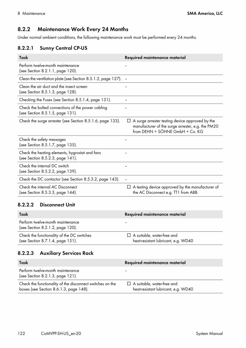
8 Maintenance SMA America, LLC
122 CoMVPP-SH-US_en-20 System Manual
8.2.2 Maintenance Work Every 24 MonthsUnder normal ambient conditions, the following maintenance work must be performed every 24 months.
8.2.2.1 Sunny Central CP-US
8.2.2.2 Disconnect Unit
8.2.2.3 Auxiliary Services Rack
Task Required maintenance materialPerform twelve-month maintenance (see Section 8.2.1.1, page 120).
‒
Clean the ventilation plate (see Section 8.5.1.2, page 127). ‒Clean the air duct and the insect screen (see Section 8.5.1.3, page 128).
‒
Checking the Fuses (see Section 8.5.1.4, page 131). ‒Check the bolted connections of the power cabling (see Section 8.5.1.5, page 131).
‒
Check the surge arrester (see Section 8.5.1.6, page 133). A surge arrester testing device approved by the manufacturer of the surge arrester, e.g. the PM20 from DEHN + SÖHNE GmbH + Co. KG
Check the safety messages (see Section 8.5.1.7, page 135).
‒
Check the heating elements, hygrostat and fans (see Section 8.5.2.3, page 141).
‒
Check the internal DC switch (see Section 8.5.2.2, page 139).
‒
Check the DC contactor (see Section 8.5.3.2, page 143). ‒Check the internal AC Disconnect (see Section 8.5.3.3, page 144).
A testing device approved by the manufacturer of the AC Disconnect e.g. TT1 from ABB.
Task Required maintenance materialPerform twelve-month maintenance (see Section 8.2.1.2, page 120).
‒
Check the functionality of the DC switches (see Section 8.7.1.4, page 151).
A suitable, water-free and heat-resistant lubricant, e.g. WD40
Task Required maintenance materialPerform twelve-month maintenance (see Section 8.2.1.3, page 121).
‒
Check the functionality of the disconnect switches on the boxes (see Section 8.6.1.3, page 148).
A suitable, water-free and heat-resistant lubricant, e.g. WD40

SMA America, LLC 8 Maintenance
System Manual CoMVPP-SH-US_en-20 123
8.2.2.4 MV Transformer
8.2.3 Unscheduled Maintenance8.2.3.1 All Devices
8.2.3.2 MV Transformer
8.3 Repair Plan and Spare Parts8.3.1 Demand-Based Repairs8.3.1.1 Sunny Central CP-US
Task Required maintenance materialPerform twelve-month maintenance (see Section 8.2.1.5, page 121).
‒
Check the oil separator and oil tray (see Section 8.8.1.2, page 152).*
* For the option with oil separator and oil tray
Pump Oil separator 4" Petro-Pipe w/1.5" male fitting 16"
long, PIT-416Test the transformer oil (see Section 8.8.1.4, page 154). ‒
Task Required maintenance materialContact the SMA Service Line after each short circuit. ‒
Task Required maintenance materialIn the event of an MV transformer fault, check the oil separator and oil tray (see Section 8.8.1.2, page 152).
‒
In the event of a high pressure alarm, reduce the tank pressure by 2 PSIG (see Section 8.8.1.7, page 156).
-
In the event of a low pressure alarm, increace the tank pressure by 2 PSIG (see Section 8.8.1.7, page 156)
Nitrogen gas tank, regulator, hose with Schrader valve nozzle.
Task Required maintenance materialReading off the Replacement Interval Meter (see Section 8.5.3.4, page 145)Replacing the GFDI / Soft Grounding / ABB high-performance circuit breaker*
* Contact the SMA Service Line.
‒
Replacing the surge arrester A surge arrester testing device approved by the manufacturer of the surge arrester, e.g. the PM20 from DEHN + SÖHNE GmbH + Co. KG.

8 Maintenance SMA America, LLC
124 CoMVPP-SH-US_en-20 System Manual
8.3.1.2 MV Transformer
8.3.2 Repair Every 10 Years8.3.2.1 Sunny Central CP-US
8.3.3 Repair Every 13 Years8.3.3.1 Sunny Central CP-US
8.4 General MaintenanceThis section contains general maintenance work that is applicable to all devices of the MV Power Platform. The tasks described in this section must only be performed when the MV Power Platform is disconnected.
8.4.1 Optical Inspection• Check the device for optical faults such as discoloration, dirt, damage and scratches on the enclosure.
If optical faults are present, these are to be repaired immediately.• Ensure that there are no objects on or around the MV Power Platform and its devices that are flammable or that can
otherwise endanger the operational reliability of the MV Power Platform.• Check the welded joints required for attaching the devices for damage.
Contact the SMA Service Line if any welded joints are damaged.
8.4.2 Cleaning the Interior
Procedure:• Ensure that the switch cabinet is sealed.
Task Required maintenance materialExchanging the Fuses (Green Power Fuses) in the MV Transformer (see Section 8.8.1.5, page 155)
Fuses Mersen AJT100
Task Required maintenance materialReplacing the 24 V Power Supply Units*
* Contact the SMA Service Line.
‒
Task Required maintenance materialReplacing the Inverter Bridge Fan*
* Contact the SMA Service Line.
‒Replacing the interior fan* ‒
Danger to life through electric shock due to incorrectly disconnected MV Power PlatformIf the MV Power Platform and its devices are not correctly disconnected, dangerous voltages can be present on the components which result in death or serious injury when touching them.
• Disconnect the MV Power Platform (see Section 5.3, page 65).• Ensure that the MV Power Platform and its devices are voltage-free.

SMA America, LLC 8 Maintenance
System Manual CoMVPP-SH-US_en-20 125
• Remove dirt and dust from the interior of the switch cabinet and from all assemblies (e.g. DC load-break switch and AC circuit breaker).
• Check for leaks.If leaks are present, fix the leaks.
• Remove moisture.
8.4.3 Checking the Seals
Figure 41: Section drawing with top view of a door seal (example)
Required maintenance material (not included in the scope of delivery): A suitable water-free, heat-resistant lubricant Talcum, petroleum jelly or wax for maintaining the seals
Procedure:• Check whether the seals in the sealing area show any damage.
If seals are damaged, contact the SMA Service Line.• Maintain seals with talcum, petroleum jelly or wax. This prevents frost damage.
Danger to life through electric shock due to incorrectly disconnected MV Power PlatformIf the MV Power Platform and its devices are not correctly disconnected, dangerous voltages can be present on the components which result in death or serious injury when touching them.
• Disconnect the MV Power Platform (see Section 5.3, page 65).• Ensure that the MV Power Platform and its devices are voltage-free.
Position DesignationA SealB Side panelC Sealing areaD HingeE DoorF Frame construction

8 Maintenance SMA America, LLC
126 CoMVPP-SH-US_en-20 System Manual
8.4.4 Checking the Latches, Door Stops and Hinges
Required maintenance material (not included in the scope of delivery): A suitable water-free, heat-resistant lubricant
Procedure:• Check whether the doors latch easily. Open and close the doors several times.
If the doors do not latch easily, lubricate all moving parts of the latch. • Check whether the doors can be held in place.
If the doors cannot be held in place, lubricate the door stops.• Check whether the door hinges move easily.
If the door hinges do not move easily, treat the hinges with lubricant.• Lubricate all moving parts and movement points.• If the MV Power Platform is installed in regions where below-freezing temperatures occur, apply non-greasing
antifreeze to the profile cylinder of the door locks and the key switches in order to protect against freezing.
8.4.5 Checking the Switch Cabinet for Corrosion
Required maintenance material (not included in the scope of delivery): Use touch-up sticks, paint brushes, cans of spray paint or, alternatively, 2K-PUR acrylic paint in the appropriate
RAL color to repair small-area surface damages. Observe the relevant instructions of the paint manufacturer. Use touch-up paint or alternatively 2K-PUR acrylic paint in the appropriate RAL color to repair large-area surface
damages. Observe the relevant instructions of the paint manufacturer.
Abrasive cloth Degreaser
Danger to life through electric shock due to incorrectly disconnected MV Power PlatformIf the MV Power Platform and its devices are not correctly disconnected, dangerous voltages can be present on the components which result in death or serious injury when touching them.
• Disconnect the MV Power Platform (see Section 5.3, page 65).• Ensure that the MV Power Platform and its devices are voltage-free.
Position RAL color Color schemeInverter roof RAL 7004 Signal grayPlatform base RAL 7005 Mouse grayInverter and disconnect enclosures RAL 9016 Traffic white
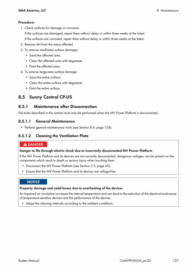
SMA America, LLC 8 Maintenance
System Manual CoMVPP-SH-US_en-20 127
Procedure:1. Check surfaces for damage or corrosion.
If the surfaces are damaged, repair them without delay or within three weeks at the latest.If the surfaces are corroded, repair them without delay or within three weeks at the latest.
2. Remove dirt from the areas affected.3. To remove small-area surface damages:
• Sand the affected area.• Clean the affected area with degreaser.• Paint the affected area.
4. To remove large-area surface damage:• Sand the entire surface.• Clean the entire surface with degreaser.• Paint the entire surface.
8.5 Sunny Central CP-US8.5.1 Maintenance after DisconnectionThe tasks described in this section must only be performed when the MV Power Platform is disconnected.
8.5.1.1 General Maintenance• Perform general maintenance work (see Section 8.4, page 124).
8.5.1.2 Cleaning the Ventilation Plate
Danger to life through electric shock due to incorrectly disconnected MV Power PlatformIf the MV Power Platform and its devices are not correctly disconnected, dangerous voltages can be present on the components which result in death or serious injury when touching them.
• Disconnect the MV Power Platform (see Section 5.3, page 65).• Ensure that the MV Power Platform and its devices are voltage-free.
Property damage and yield losses due to overheating of the devicesAn impaired air circulation increases the internal temperature and can lead to the reduction of the electrical endurance of temperature-sensitive devices and the performance of the devices.
• Adapt the cleaning intervals according to the ambient conditions.
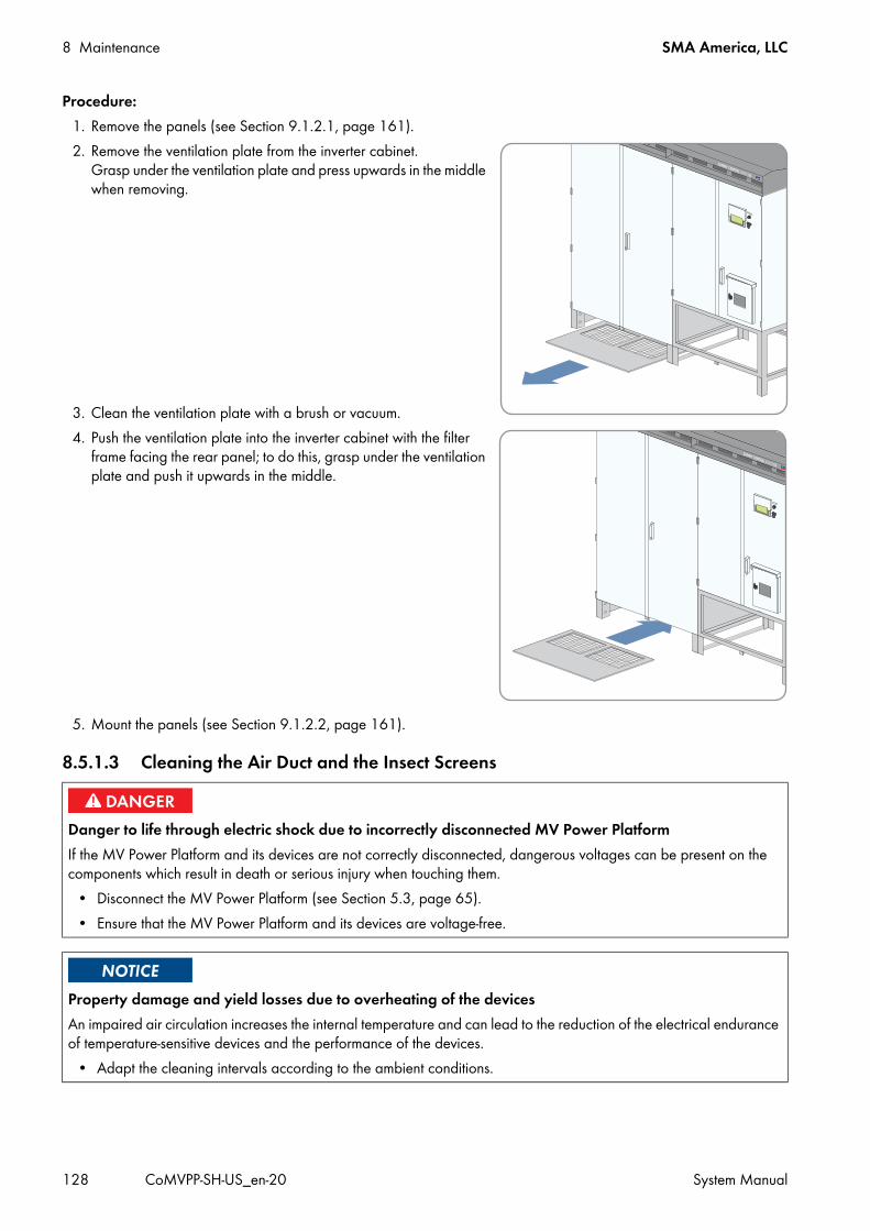
8 Maintenance SMA America, LLC
128 CoMVPP-SH-US_en-20 System Manual
Procedure:1. Remove the panels (see Section 9.1.2.1, page 161).2. Remove the ventilation plate from the inverter cabinet.
Grasp under the ventilation plate and press upwards in the middle when removing.
3. Clean the ventilation plate with a brush or vacuum.4. Push the ventilation plate into the inverter cabinet with the filter
frame facing the rear panel; to do this, grasp under the ventilation plate and push it upwards in the middle.
5. Mount the panels (see Section 9.1.2.2, page 161).
8.5.1.3 Cleaning the Air Duct and the Insect Screens
Danger to life through electric shock due to incorrectly disconnected MV Power PlatformIf the MV Power Platform and its devices are not correctly disconnected, dangerous voltages can be present on the components which result in death or serious injury when touching them.
• Disconnect the MV Power Platform (see Section 5.3, page 65).• Ensure that the MV Power Platform and its devices are voltage-free.
Property damage and yield losses due to overheating of the devicesAn impaired air circulation increases the internal temperature and can lead to the reduction of the electrical endurance of temperature-sensitive devices and the performance of the devices.
• Adapt the cleaning intervals according to the ambient conditions.

SMA America, LLC 8 Maintenance
System Manual CoMVPP-SH-US_en-20 129
Procedure:1. Remove the screws of the right-hand insect screen. Use an Allen
key.
2. Pull the bottom of the right-hand insect screen forward. This removes the insect screen.
3. Remove the screws of the left-hand insect screen. Use an Allen key.
4. Pull the bottom of the left-hand insect screen forward. This removes the insect screen.
5. Vacuum the air duct from the outside or clean it with a brush.
6. Vacuum the insect screens or clean them with a brush.7. Check the insect screens for visible damage.
The insect screens are not damaged. The insect screens are damaged?
• Replace the damaged insect screens.

8 Maintenance SMA America, LLC
130 CoMVPP-SH-US_en-20 System Manual
8. Insert the right-hand insect screen.
9. Screw the right-hand insect screen in place. Use an Allen key. Torque: 177 in-lb. (20 Nm).
10. Insert the left-hand insect screen.
11. Screw the left-hand insect screen in place. Use an Allen key. Torque: 177 in-lb. (20 Nm)
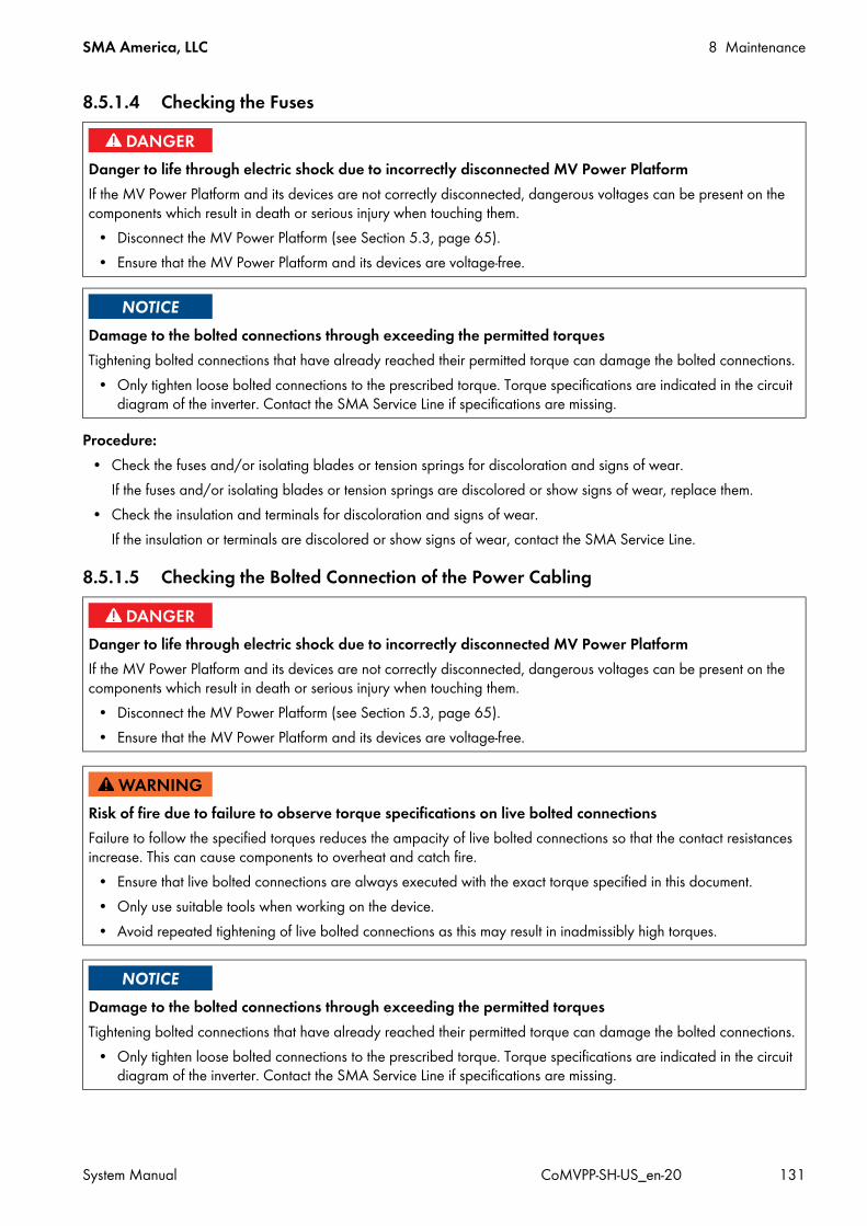
SMA America, LLC 8 Maintenance
System Manual CoMVPP-SH-US_en-20 131
8.5.1.4 Checking the Fuses
Procedure:• Check the fuses and/or isolating blades or tension springs for discoloration and signs of wear.
If the fuses and/or isolating blades or tension springs are discolored or show signs of wear, replace them.• Check the insulation and terminals for discoloration and signs of wear.
If the insulation or terminals are discolored or show signs of wear, contact the SMA Service Line.
8.5.1.5 Checking the Bolted Connection of the Power Cabling
Danger to life through electric shock due to incorrectly disconnected MV Power PlatformIf the MV Power Platform and its devices are not correctly disconnected, dangerous voltages can be present on the components which result in death or serious injury when touching them.
• Disconnect the MV Power Platform (see Section 5.3, page 65).• Ensure that the MV Power Platform and its devices are voltage-free.
Damage to the bolted connections through exceeding the permitted torquesTightening bolted connections that have already reached their permitted torque can damage the bolted connections.
• Only tighten loose bolted connections to the prescribed torque. Torque specifications are indicated in the circuit diagram of the inverter. Contact the SMA Service Line if specifications are missing.
Danger to life through electric shock due to incorrectly disconnected MV Power PlatformIf the MV Power Platform and its devices are not correctly disconnected, dangerous voltages can be present on the components which result in death or serious injury when touching them.
• Disconnect the MV Power Platform (see Section 5.3, page 65).• Ensure that the MV Power Platform and its devices are voltage-free.
Risk of fire due to failure to observe torque specifications on live bolted connectionsFailure to follow the specified torques reduces the ampacity of live bolted connections so that the contact resistances increase. This can cause components to overheat and catch fire.
• Ensure that live bolted connections are always executed with the exact torque specified in this document.• Only use suitable tools when working on the device.• Avoid repeated tightening of live bolted connections as this may result in inadmissibly high torques.
Damage to the bolted connections through exceeding the permitted torquesTightening bolted connections that have already reached their permitted torque can damage the bolted connections.
• Only tighten loose bolted connections to the prescribed torque. Torque specifications are indicated in the circuit diagram of the inverter. Contact the SMA Service Line if specifications are missing.

8 Maintenance SMA America, LLC
132 CoMVPP-SH-US_en-20 System Manual
Figure 42: Position of the power cabling for connection with terminal lugs
Procedure:
2. Check whether all screw connections for the power cabling are tight. In lieu of mechanical torque checks, inspect all power cabling connections using thermal imaging as recommended by NFPA 70B and per ASTM E1934 and/or ISO/AWI 10881. Baseline thermal imaging is recommended after initial startup and commissioning for comparisons on an annual basis. If screw connections are loose, tighten them with a torque wrench.
3. Check insulation and connections for discoloration and changed appearance. If insulation and connections are discolored or changed, contact the SMA Service Line.
4. Check the screw connections for damage and contact elements for corrosion.If screw connections are damaged or contact elements are corroded, contact the SMA Service Line.
Checking the bolted connection of the power cablingThe bolted connections of the power cabling only need to be checked if no DC Disconnect Units are used and the connection of the power cabling was made by the customer.The bolted connections of the AC connection power cabling do not need to be checked.
Position DesignationA For negative grounding: connection busbar for DC − cables
For positive grounding: connection busbar for DC+ cablesB For negative grounding: connection lugs for DC − cables
For negative grounding: connection lugs for DC+ cablesC Connection lugs for AC cablesD Connection busbar for grounding cable
1.Danger to life due to electric shock or electric arc by touching live components
• Disconnect the inverter and wait 15 minutes until the capacitors have discharged completely (see Section 5.3, page 65).

SMA America, LLC 8 Maintenance
System Manual CoMVPP-SH-US_en-20 133
8.5.1.6 Checking the Surge Arrester
Figure 43: Position of the surge arrester (example)
Additionally required maintenance material (not included in the scope of delivery): A testing device approved by the manufacturer of the surge arrester
(e.g. the PM20 from DEHN + SÖHNE GmbH + Co. KG.)Procedure:
1. Open the interface cabinet.2. Check the surge arresters (see the testing device documentation).3. Check whether the ready indicator of one of the surge arresters is red.
If the ready indicator of one of the surge arresters is red, replace the surge arresters. • Remove the cables of the surge arrester. Mark the cables. The cables must be reconnected to the same terminals
later. • Open the terminal and remove the surge arrester upwards out
of the DIN rail.
Danger to life through electric shock due to incorrectly disconnected MV Power PlatformIf the MV Power Platform and its devices are not correctly disconnected, dangerous voltages can be present on the components which result in death or serious injury when touching them.
• Disconnect the MV Power Platform (see Section 5.3, page 65).• Ensure that the MV Power Platform and its devices are voltage-free.
Position DesignationA Ready indicator of the surge arrester

8 Maintenance SMA America, LLC
134 CoMVPP-SH-US_en-20 System Manual
• Insert the new surge arrester into the DIN rail from above and press it against the DIN rail.
• Connect the cables to the same terminals of the surge arrester from which they were previously removed.4. Close the interface cabinet.

SMA America, LLC 8 Maintenance
System Manual CoMVPP-SH-US_en-20 135
8.5.1.7 Checking the Safety Messages
Inverter without Integrated DC Switch
Figure 44: Safety messages on the inverter
Danger to life through electric shock due to incorrectly disconnected MV Power PlatformIf the MV Power Platform and its devices are not correctly disconnected, dangerous voltages can be present on the components which result in death or serious injury when touching them.
• Disconnect the MV Power Platform (see Section 5.3, page 65).• Ensure that the MV Power Platform and its devices are voltage-free.
Position SMA order number DesignationA 86-0043464 Warning label general SC-US EN
86-430042 Warning label Arc Flash Hazard ProtectionB 86-00480030 Only with order option AC Disconnect: Photovoltaic System AC Disconnect
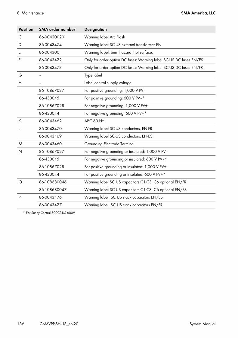
8 Maintenance SMA America, LLC
136 CoMVPP-SH-US_en-20 System Manual
C 86-00420020 Warning label Arc FlashD 86-0043474 Warning label SC-US external transformer ENE 86-004300 Warning label, burn hazard, hot surface.F 86-0043472 Only for order option DC fuses: Warning label SC-US DC fuses EN/ES
86-0043473 Only for order option DC fuses: Warning label SC-US DC fuses EN/FRG ‒ Type labelH ‒ Label control supply voltageI 86-10867027 For positive grounding: 1,000 V PV‒
86-430045 For positive grounding: 600 V PV‒*86-10867028 For negative grounding: 1,000 V PV+86-430044 For negative grounding: 600 V PV+*
K 86-0043462 ABC 60 HzL 86-0043470 Warning label SC-US conductors, EN-FR
86-0043469 Warning label SC-US conductors, EN-ESM 86-0043460 Grounding Electrode TerminalN 86-10867027 For negative grounding or insulated: 1,000 V PV‒
86-430045 For negative grounding or insulated: 600 V PV‒*86-10867028 For positive grounding or insulated: 1,000 V PV+86-430044 For positive grounding or insulated: 600 V PV+*
O 86-108680046 Warning label SC US capacitors C1-C3, C6 optional EN/FR86-108680047 Warning label SC US capacitors C1-C3, C6 optional EN/ES
P 86-0043476 Warning label, SC US stack capacitors EN/ES86-0043477 Warning label, SC US stack capacitors EN/FR
* For Sunny Central 500CP-US 600V
Position SMA order number Designation

SMA America, LLC 8 Maintenance
System Manual CoMVPP-SH-US_en-20 137
Inverter with Integrated DC Switch
Figure 45: Safety messages on the inverter
Position SMA order number DesignationA 86-0043464 Warning label general SC-US EN
86-430042 Warning label Arc Flash Hazard ProtectionB 86-0033325 Label "Closed"C 86-00480030 Label "Photovoltaic System AC Disconnect"D 86-101400.1 Label "DC-Switch"E 86-0033324 Label "Open"F 86-00480020 Warning label Arc FlashG 86-0043474 Warning label SC-US external transformer ENH 86-0033326 Warning label Electric Shock due to Live Voltage EN/ES
86-0033327 Warning label Electric Shock due to Live Voltage EN/FR
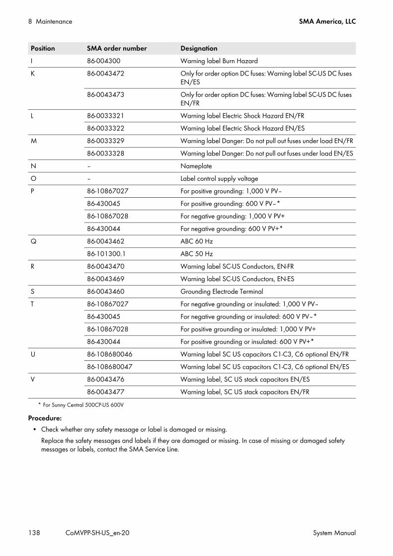
8 Maintenance SMA America, LLC
138 CoMVPP-SH-US_en-20 System Manual
Procedure:• Check whether any safety message or label is damaged or missing.
Replace the safety messages and labels if they are damaged or missing. In case of missing or damaged safety messages or labels, contact the SMA Service Line.
I 86-004300 Warning label Burn HazardK 86-0043472 Only for order option DC fuses: Warning label SC-US DC fuses
EN/ES86-0043473 Only for order option DC fuses: Warning label SC-US DC fuses
EN/FRL 86-0033321 Warning label Electric Shock Hazard EN/FR
86-0033322 Warning label Electric Shock Hazard EN/ESM 86-0033329 Warning label Danger: Do not pull out fuses under load EN/FR
86-0033328 Warning label Danger: Do not pull out fuses under load EN/ESN ‒ NameplateO ‒ Label control supply voltageP 86-10867027 For positive grounding: 1,000 V PV‒
86-430045 For positive grounding: 600 V PV‒*86-10867028 For negative grounding: 1,000 V PV+86-430044 For negative grounding: 600 V PV+*
Q 86-0043462 ABC 60 Hz86-101300.1 ABC 50 Hz
R 86-0043470 Warning label SC-US Conductors, EN-FR86-0043469 Warning label SC-US Conductors, EN-ES
S 86-0043460 Grounding Electrode TerminalT 86-10867027 For negative grounding or insulated: 1,000 V PV‒
86-430045 For negative grounding or insulated: 600 V PV‒*86-10867028 For positive grounding or insulated: 1,000 V PV+86-430044 For positive grounding or insulated: 600 V PV+*
U 86-108680046 Warning label SC US capacitors C1-C3, C6 optional EN/FR86-108680047 Warning label SC US capacitors C1-C3, C6 optional EN/ES
V 86-0043476 Warning label, SC US stack capacitors EN/ES86-0043477 Warning label, SC US stack capacitors EN/FR
* For Sunny Central 500CP-US 600V
Position SMA order number Designation

SMA America, LLC 8 Maintenance
System Manual CoMVPP-SH-US_en-20 139
8.5.2 Maintenance After Connection of the Supply Voltage8.5.2.1 Safety
8.5.2.2 Checking the Integrated DC Switch
Figure 46: Indicators and switches on the Internal DC Switch
Danger to life due to electric shockHigh voltages are present in the conductive components of the inverter. Touching live components results in death or serious injury due to electric shock.
• Switch the inverter key switch to the Stop position and ensure that the device cannot be accidentally reconnected.• After disconnecting the inverter from voltage sources, wait at least 15 minutes for the capacitors of the
Sunny Central to discharge completely.• Do not touch any live components in the inverter or the medium-voltage grid. Comply with all applicable safety
regulations for handling medium-voltage grids.• Wear Hazard Risk Category 2 personal protective equipment.• Always perform work in compliance with the regulations specified in 29 CFR, Chapter XVII, Part 1910 (OSHA),
NEC, and NFPA 70E.
Danger to life through electric shock due to incorrectly disconnected MV Power PlatformIf the MV Power Platform and its devices are not correctly disconnected, dangerous voltages can be present on the components which result in death or serious injury when touching them.
• Disconnect the MV Power Platform (see Section 5.3, page 65).• Ensure that the MV Power Platform and its devices are voltage-free.
Position DescriptionA Spring status indicator (not applicable for these motor driven switches)B Position indicatorC ON buttonD OFF button

8 Maintenance SMA America, LLC
140 CoMVPP-SH-US_en-20 System Manual
Requirements before proceeding: The inverter is operating without faults or errors.
Proceedure:
2. Open the doors of the inverter cabinet.3. Reconnect the supply voltage(see Section 5.4, page 72).
The internal fan and the inverter bridge fan start up for a short time. The internal fan and inverter bridge fan do not start?
• Contact the SMA Service Line.
Context:The Integrated DC Switch option consists of a control actuator switch on the inverter door, red and green indictor lights on the inverter door, and two motor driven DC load-break switches inside the inverter. This proceedure tests the correct operation of each of these components.
Proceedure: 1. Verify that the Integrated DC Switch control actuator switch on the inverter door is in the ON position, and that the
green CLOSED indicator light is illuminated.2. Switch the key switch of the inverter to Stop.3. Check whether the red OPEN indicator light on the inverter door is illuminated, indicating that the DC load-break
switches are open.4. Open the doors of the interface cabinet.5. Check whether the DC load-break switches are both indicating the Off position. If either of the DC load-break
switches are not indicating the Off position, contact the SMA Service Line. 6. Close the doors of the interface cabinet.7. Switch the key switch of the inverter to Start.8. Check whether the green CLOSED indicator is illuminated, indicating that the DC load-break switches are closed.9. Open the doors of the interface cabinet.
10. Check whether the DC load-break switches are indicating the On position. If the DC load-break switches are not both indicating the On position, contact the SMA Service Line.
11. Switch the Integrated DC Switch control actuator switch on the inverter door to OFF.12. Check whether the DC load-break switches are both indicating the Off position. If either of the DC load-break
switches are not indicating the Off position, contact the SMA Service Line.13. Check whether the red OPEN indicator light on the inverter door is illuminated, indicating that the DC load-break
switches are open.14. Test the switching process three times. Check each time whether the DC load-break switches have switched.15. Close the doors of the interface cabinet.
1.Danger to life due to electric shock or electric arc by touching live components
• Disconnect the inverter and wait 15 minutes until the capacitors have discharged completely.

SMA America, LLC 8 Maintenance
System Manual CoMVPP-SH-US_en-20 141
8.5.2.3 Checking the Heating Elements, Hygrostat and Fans
Figure 47: Positions of the heating element, hygrostat and fans
Danger to life through electric shock due to incorrectly disconnected MV Power PlatformIf the MV Power Platform and its devices are not correctly disconnected, dangerous voltages can be present on the components which result in death or serious injury when touching them.
• Disconnect the MV Power Platform (see Section 5.3, page 65).• Ensure that the MV Power Platform and its devices are voltage-free.
Risk of burns due to hot heating elementsDuring the functional test, the heating element becomes hot. There is a risk of burns if you touch the heating element without protective gloves.
• Do not touch heating elements with bare hands.• Wear personal protective equipment.• Always maintain a suitable distance when checking the function of the heating elements.
Low humidityIf humidity is below 50%, you will not be able to perform the function test since the minimum value of the hygrostat is 50%.
Position DesignationA Heating elementB FansC Hygrostat
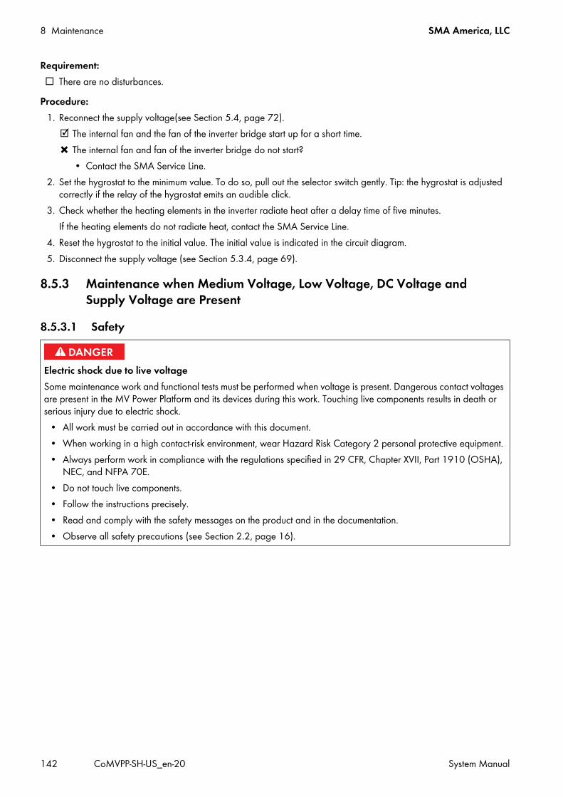
8 Maintenance SMA America, LLC
142 CoMVPP-SH-US_en-20 System Manual
Requirement: There are no disturbances.
Procedure:1. Reconnect the supply voltage(see Section 5.4, page 72).
The internal fan and the fan of the inverter bridge start up for a short time. The internal fan and fan of the inverter bridge do not start?
• Contact the SMA Service Line.2. Set the hygrostat to the minimum value. To do so, pull out the selector switch gently. Tip: the hygrostat is adjusted
correctly if the relay of the hygrostat emits an audible click.3. Check whether the heating elements in the inverter radiate heat after a delay time of five minutes.
If the heating elements do not radiate heat, contact the SMA Service Line.4. Reset the hygrostat to the initial value. The initial value is indicated in the circuit diagram.5. Disconnect the supply voltage (see Section 5.3.4, page 69).
8.5.3 Maintenance when Medium Voltage, Low Voltage, DC Voltage and Supply Voltage are Present
8.5.3.1 Safety
Electric shock due to live voltageSome maintenance work and functional tests must be performed when voltage is present. Dangerous contact voltages are present in the MV Power Platform and its devices during this work. Touching live components results in death or serious injury due to electric shock.
• All work must be carried out in accordance with this document.• When working in a high contact-risk environment, wear Hazard Risk Category 2 personal protective equipment.• Always perform work in compliance with the regulations specified in 29 CFR, Chapter XVII, Part 1910 (OSHA),
NEC, and NFPA 70E.• Do not touch live components.• Follow the instructions precisely.• Read and comply with the safety messages on the product and in the documentation.• Observe all safety precautions (see Section 2.2, page 16).

SMA America, LLC 8 Maintenance
System Manual CoMVPP-SH-US_en-20 143
8.5.3.2 Checking the DC Contactor in Units without the Integrated DC Switch
Figure 48: Position of the DC contactor
Requirements: Supply voltage is present. DC voltage is present.
Procedure:1. Switch the inverter to Stop. By doing so, the DC contactor is audibly switched off.2. Open the doors of the interface cabinet.3. Check the switching state of the DC contactor.
The DC contactor is switched off.
Electric shock due to live voltageSome maintenance work and functional tests must be performed when voltage is present. Dangerous contact voltages are present in the MV Power Platform and its devices during this work. Touching live components results in death or serious injury due to electric shock.
• All work must be carried out in accordance with this document.• When working in a high contact-risk environment, wear Hazard Risk Category 2 personal protective equipment.• Always perform work in compliance with the regulations specified in 29 CFR, Chapter XVII, Part 1910 (OSHA),
NEC, and NFPA 70E.• Do not touch live components.• Follow the instructions precisely.• Read and comply with the safety messages on the product and in the documentation.• Observe all safety precautions (see Section 2.2, page 16).
Position DesignationA DC contactor

8 Maintenance SMA America, LLC
144 CoMVPP-SH-US_en-20 System Manual
The DC contactor does not switch off?• Contact the SMA Service Line.
4. Close the doors of the interface cabinet.5. Switch the inverter to Start.6. Open the doors of the interface cabinet.7. Check the switching state of the DC contactor.
The DC contactor is switched off. The DC contactor does not switch off?
• Contact the SMA Service Line.8. Switch the inverter to Stop.9. Test the switching process three times. Check three times whether the DC contactor has switched.
10. Close the doors of the interface cabinet.
8.5.3.3 Checking the AC Disconnect
Figure 49: Position of the AC Disconnect
Electric shock due to live voltageSome maintenance work and functional tests must be performed when voltage is present. Dangerous contact voltages are present in the MV Power Platform and its devices during this work. Touching live components results in death or serious injury due to electric shock.
• All work must be carried out in accordance with this document.• When working in a high contact-risk environment, wear Hazard Risk Category 2 personal protective equipment.• Always perform work in compliance with the regulations specified in 29 CFR, Chapter XVII, Part 1910 (OSHA),
NEC, and NFPA 70E.• Do not touch live components.• Follow the instructions precisely.• Read and comply with the safety messages on the product and in the documentation.• Observe all safety precautions (see Section 2.2, page 16).

SMA America, LLC 8 Maintenance
System Manual CoMVPP-SH-US_en-20 145
Additionally required maintenance material (not included in the scope of delivery): A testing device approved by the manufacturer of the AC Disconnect, e.g. TT1 from ABB
Procedure:• Use the testing device to check whether the AC Disconnect is ready for operation (instructions for testing are included
in the documentation of the testing device).If a fault occurs during the test, contact the SMA Service Line.
8.5.3.4 Reading off the Replacement Interval Meter1. Log in to the user interface.2. Enter the password in the appropriate field on the homepage and confirm with [Login].3. Select Data > Device.4. Select .
A list of all existing device types appears.5. Select the device type Sunny Central.
A list appears containing all existing devices of this type.6. Select the desired device from the list.7. Select the tab Instantaneous values.8. Check the following meters and compare them with the replacement intervals (see Section 4.1, page 22):
• Number of GFDI trippings in the instantaneous value CntGfdiTripSw. If replacement of the GFDI is necessary, the error message 7714 will appear on the display.
• Number of switching cycles of the Remote Switch Unit of the GFDI in the instantaneous value CntGfdiSw.9. If the corresponding instantaneous value equals or is greater than the replacement interval of the device, replace the
device. Contact the SMA Service Line.
8.6 Auxiliary Services Rack8.6.1 Maintenance after DisconnectionThe tasks described in this section must only be performed when the MV Power Platform is disconnected.
8.6.1.1 General Maintenance• Perform general maintenance work (see Section 8.4, page 124).
Position DesignationA OFF buttonB ON buttonC Spring status indicatorD Position indicator

8 Maintenance SMA America, LLC
146 CoMVPP-SH-US_en-20 System Manual
8.6.1.2 Checking the Safety Messages
Danger to life through electric shock due to incorrectly disconnected MV Power PlatformIf the MV Power Platform and its devices are not correctly disconnected, dangerous voltages can be present on the components which result in death or serious injury when touching them.
• Disconnect the MV Power Platform (see Section 5.3, page 65).• Ensure that the MV Power Platform and its devices are voltage-free.

SMA America, LLC 8 Maintenance
System Manual CoMVPP-SH-US_en-20 147
Figure 50: Positions of the safety messages
Position SMA order number DesignationA 86-79616 Warning label, hot surfaceB 86-00338 Warning label, risk of electrical shockC - Type label

8 Maintenance SMA America, LLC
148 CoMVPP-SH-US_en-20 System Manual
Procedure:• Check whether any safety message or label is damaged or missing.
Replace the safety messages and labels if they are damaged or missing. In case of missing or damaged safety messages or labels, contact the SMA Service Line.
8.6.1.3 Checking the Functionality of the Disconnect Switches
Required maintenance material (not included in the scope of delivery): A suitable, water-free and heat-resistant lubricant, e.g. WD40
Procedure:• Check whether the disconnect switches of the boxes in the Auxiliary Services Rack function correctly.
If the disconnect switches can only be switched with difficulty, treat the switch mechanisms with lubricant.8.6.1.4 Checking the Functionality of the Sun Shield
1. Unlock latches.2. Lift latch T-handles and twist.
The sun shield will slightly open to approximately 45°.3. Use the push stick located in the bottom of the Auxiliary Services Rack to push the sun shield to a horizontal position.
The mechanical arm locks when reaching this position.4. Disengage the mechanical arm.
• Use the push stick to slightly lift the sun shield.• Pull the chain attached to the eyebolt to disengage the mechanical arm.• Slowly let the sun shield drop to approximately 45°.
5. Place the push stick back into the Auxiliary Services Rack.6. Push the sun shield into the closed position.7. Twist the T-handles to engage the latches and recess the T-handles.8. Lock latches.9. If the correct functioning of the sun shield is not guaranteed, contact the SMA Service Line.
D 86-01250117 Label, Main disconnectE 86-04053 Warning label, Arc Flash and Shock HazardF 86-01250119 Label, max. 250 W eachG - Reference designationH 86-01250118 Label, Platform supply - Off - Generator supplyI 86-00336 Label, operating the sunshadeK - Type labelL - Type label
Danger to life through electric shock due to incorrectly disconnected MV Power PlatformIf the MV Power Platform and its devices are not correctly disconnected, dangerous voltages can be present on the components which result in death or serious injury when touching them.
• Disconnect the MV Power Platform (see Section 5.3, page 65).• Ensure that the MV Power Platform and its devices are voltage-free.
Position SMA order number Designation

SMA America, LLC 8 Maintenance
System Manual CoMVPP-SH-US_en-20 149
8.7 Disconnect Unit8.7.1 Maintenance after DisconnectionThe tasks described in this section must only be performed when the MV Power Platform is disconnected.
8.7.1.1 General Maintenance• Perform general maintenance work (see Section 8.4, page 124).
8.7.1.2 Checking the Bolted Connections of the Power Cabling
Danger to life through electric shock due to incorrectly disconnected MV Power PlatformIf the MV Power Platform and its devices are not correctly disconnected, dangerous voltages can be present on the components which result in death or serious injury when touching them.
• Disconnect the MV Power Platform (see Section 5.3, page 65).• Ensure that the MV Power Platform and its devices are voltage-free.
Risk of fire due to failure to observe torque specifications on live bolted connectionsFailure to follow the specified torques reduces the ampacity of live bolted connections so that the contact resistances increase. This can cause components to overheat and catch fire.
• Ensure that live bolted connections are always executed with the exact torque specified in this document.• Only use suitable tools when working on the device.• Avoid repeated tightening of live bolted connections as this may result in inadmissibly high torques.
Damage to the bolted connections through exceeding the permitted torquesTightening bolted connections that have already reached their permitted torque can damage the bolted connections.
• Only tighten loose bolted connections to the prescribed torque. Torque specifications are indicated in the circuit diagram of the inverter. Contact the SMA Service Line if specifications are missing.
Checking the bolted connection of the power cablingThe bolted connections of the power cabling only need to be checked if no DC Disconnect Units are used and the connection of the power cabling was made by the customer.

8 Maintenance SMA America, LLC
150 CoMVPP-SH-US_en-20 System Manual
Figure 51: Customer DC connection points in the Disconnect Units
Procedure:• Check whether all bolted connections for the power cabling are tight. In lieu of mechanical torque checks, inspect
all power cabling connections using thermal imaging as recommended by NFPA 70B and per ASTM E1934 and/or ISO/AWI 10881. Baseline thermal imaging is recommended after initial startup and commissioning for comparisons on an annual basis.If bolted connections are loose, tighten them with a torque wrench.
• Check insulation and connections for discoloration and changed appearance.If insulation and connections are discolored or changed, contact the SMA Service Line.
• Replace damaged power connections and corroded contact elements.
8.7.1.3 Checking the Seal on the Front Panel
Required maintenance material (not included in the scope of delivery): A suitable water-free, heat-resistant lubricant
Procedure:• Check whether the seal on the front panel is damaged.
Position DesignationA DC input for the grounded terminal of Disconnect Unit 1B DC input for the ungrounded terminal of Disconnect Unit 1C PE connection of the Disconnect UnitsD DC input for the ungrounded terminal of Disconnect Unit 2E DC input for the grounded terminal of Disconnect Unit 2
Danger to life through electric shock due to incorrectly disconnected MV Power PlatformIf the MV Power Platform and its devices are not correctly disconnected, dangerous voltages can be present on the components which result in death or serious injury when touching them.
• Disconnect the MV Power Platform (see Section 5.3, page 65).• Ensure that the MV Power Platform and its devices are voltage-free.

SMA America, LLC 8 Maintenance
System Manual CoMVPP-SH-US_en-20 151
If the seal is damaged, contact the SMA Service Line.• Maintain the seal with talcum, petroleum jelly or wax. This prevents frost damage.
8.7.1.4 Checking the Functionality of the DC Switches
Required maintenance material (not included in the scope of delivery): A suitable, water-free and heat-resistant lubricant, e.g. WD40
Procedure:• Check whether the DC switches function correctly.
If the DC switches can only be switched with difficulty, treat the switches with lubricant.
8.8 MV Transformer8.8.1 Maintenance after DisconnectionThe tasks described in this section must only be performed when the MV Power Platform is disconnected.
8.8.1.1 General Maintenance• Perform general maintenance work (see Section 8.4, page 124).
Danger to life through electric shock due to incorrectly disconnected MV Power PlatformIf the MV Power Platform and its devices are not correctly disconnected, dangerous voltages can be present on the components which result in death or serious injury when touching them.
• Disconnect the MV Power Platform (see Section 5.3, page 65).• Ensure that the MV Power Platform and its devices are voltage-free.

8 Maintenance SMA America, LLC
152 CoMVPP-SH-US_en-20 System Manual
8.8.1.2 Checking the Oil Separator and Oil Tray
Figure 52: Position of the oil separator and oil tray
Required maintenance material (not included in the scope of delivery): Pump Oil separator 4" Petro-Pipe w/1.5" male fitting 16" long, PIT-416
Procedure:1. Remove the grill above the oil tray.2. Check whether there is oil present in the oil tray.
If there is oil present in the oil tray, pump out the oil using a pump and properly dispose of the oil.If there is no oil in the oil tray, it is not necessary to replace the oil separator.
3. After having pumped out the oil, replace the oil separator.
Position DesignationA Oil trayB Oil separator

SMA America, LLC 8 Maintenance
System Manual CoMVPP-SH-US_en-20 153
• Remove the safety ring. Press the safety ring together and pull upwards.
• Remove the grill, net, filter pad and oil separator.
• Rinse the filter pad with water. The water flows easily through the filter pad. The water flows slowly through the filter pad.
• Clean or replace the filter pad.• Clean the hollow space.• Insert the new oil separator.• Insert the new filter pad.• Insert the net and grill.• Insert the safety ring. When inserting, press the safety ring together.
4. Insert the grill above the oil tray.

8 Maintenance SMA America, LLC
154 CoMVPP-SH-US_en-20 System Manual
8.8.1.3 Cleaning the Oil Tray Behind the Oil Separator
Figure 53: Position of the oil separator and oil tray
Procedure:1. Remove the grill above the oil tray.2. Clean the area behind the oil separator extensively. Ensure that the oil separator is not blocked by impurities.3. Insert the grill above the oil tray.
8.8.1.4 Testing the Transformer Oil1. Take an oil sample and send it to a third party tester to check dissolved gas levels. 2. Compare dissolved gas analysis results to the baseline result.3. Look for abrupt changes in dissolved gas levels.4. Check all abrupt changes.
Position DesignationA Oil trayB Oil separator

SMA America, LLC 8 Maintenance
System Manual CoMVPP-SH-US_en-20 155
8.8.1.5 Exchanging the Fuses (Green Power Fuses) in the MV TransformerIf the fuses fail during internal supply voltage, you can change these in the MV transformer. Disconnect the MV Power Platform at the AC and DC sides.
Required maintenance material (not included in the scope of delivery): Fuses Mersen AJT100 (SMA order number: 61-0305)
Procedure:1. Open the doors of the MV transformer.2. Change the fuses in the fuse block.3. Close the doors of the MV transformer.
8.8.1.6 Maintaining the MV Transformer
Danger to life through electric shock due to incorrectly disconnected MV Power PlatformIf the MV Power Platform and its devices are not correctly disconnected, dangerous voltages can be present on the components which result in death or serious injury when touching them.
• Disconnect the MV Power Platform (see Section 5.3, page 65).• Ensure that the MV Power Platform and its devices are voltage-free.
Task MeasuresExterior Surfaces
• Inspect for evidence of tampering, battered metal, gouges, etc.
Any such damage should be repaired immediately.
Paint or Protective Coatings• Inspect for scratches or weathering.
Any such damage should be touched up immediately.
Tank Leaks• Check tank exterior for signs of a leak.
Any such leaks should be repaired immediately.
General Location• Check the area around the transformer for stored tools,
materials, equipment or debris.
Anything on or against the transformer should be removed.
Gauges and Controls• Check for proper operation.
Repair or replace damaged or defective equipment.
Equipment Leaks• Inspect drain cocks, plugs, fuse mountings, and
switches. Look for evidence of insulating liquid seepage around tank-wall gaskets, seals, etc.
Repair as required. Replacement of gaskets or seals in the tank wall may require that the tank be opened and the insulating liquid lowered to the appropriate level. For instruction on opening the tank and for draining and replacing the insulating liquid, refer to the Insulating Liquid Maintenance section in the Maintenance Instructions Manual.
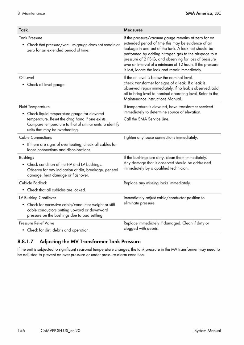
8 Maintenance SMA America, LLC
156 CoMVPP-SH-US_en-20 System Manual
8.8.1.7 Adjusting the MV Transformer Tank PressureIf the unit is subjected to significant seasonal temperature changes, the tank pressure in the MV transformer may need to be adjusted to prevent an over-pressure or under-pressure alarm condition.
Tank Pressure• Check that pressure/vacuum gauge does not remain at
zero for an extended period of time.
If the pressure/vacuum gauge remains at zero for an extended period of time this may be evidence of air leakage in and out of the tank. A leak test should be performed by adding nitrogen gas to the airspace to a pressure of 2 PSIG, and observing for loss of pressure over an interval of a minimum of 12 hours. If the pressure is lost, locate the leak and repair immediately.
Oil Level• Check oil level gauge.
If the oil level is below the nominal level, check transformer for signs of a leak. If a leak is observed, repair immediately. If no leak is observed, add oil to bring level to nominal operating level. Refer to the Maintenance Instructions Manual.
Fluid Temperature• Check liquid temperature gauge for elevated
temperature. Reset the drag hand if one exists. Compare temperature to that of similar units to identify units that may be overheating.
If temperature is elevated, have transformer serviced immediately to determine source of elevation.Call the SMA Service Line.
Cable Connections• If there are signs of overheating, check all cables for
loose connections and discolorations.
Tighten any loose connections immediately.
Bushings• Check condition of the HV and LV bushings.
Observe for any indication of dirt, breakage, general damage, heat damage or flashover.
If the bushings are dirty, clean them immediately. Any damage that is observed should be addressed immediately by a qualified technician.
Cubicle Padlock• Check that all cubicles are locked.
Replace any missing locks immediately.
LV Bushing Cantilever• Check for excessive cable/conductor weight or stiff
cable conductors putting upward or downward pressure on the bushings due to pad settling.
Immediately adjust cable/conductor position to eliminate pressure.
Pressure Relief Valve• Check for dirt, debris and operation.
Replace immediately if damaged. Clean if dirty or clogged with debris.
Task Measures
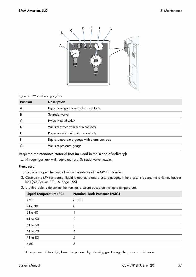
SMA America, LLC 8 Maintenance
System Manual CoMVPP-SH-US_en-20 157
Required maintenance material (not included in the scope of delivery): Nitrogen gas tank with regulator, hose, Schrader valve nozzle.
Procedure:1. Locate and open the gauge box on the exterior of the MV transformer.2. Observe the MV transformer liquid temperature and pressure gauges. If the pressure is zero, the tank may have a
leak (see Section 8.8.1.6, page 155)3. Use this table to determine the nominal pressure based on the liquid temperature.
If the pressure is too high, lower the pressure by releasing gas through the pressure relief valve.
Figure 54: MV transformer gauge box
Position DescriptionA Liquid level gauge and alarm contactsB Schrader valveC Pressure relief valveD Vacuum switch with alarm contactsE Pressure switch with alarm contactsF Liquid temperature gauge with alarm contactsG Vacuum pressure gauge
Liquid Temperature (°C) Nominal Tank Pressure (PSIG)< 21 -1 to 021to 30 031to 40 141 to 50 251 to 60 361 to 70 471 to 80 5> 80 6

8 Maintenance SMA America, LLC
158 CoMVPP-SH-US_en-20 System Manual
If the pressure is too low, add nitrogen gas through the Schrader valve.4. To lower the tank pressure:
• With a rag in hand, pull the ring on the pressure relief valve.• Let gas escape until the tank pressure reaches the target value.
5. To raise the tank pressure:• Set the regulator on the nitrogen gas tank to 8 PSIG.• Apply the nozzle to the Schrader valve until the tank pressure reaches the target value.
6. .Verify that the tank pressure in now within the acceptable range7. Close the gauge box cover.

SMA America, LLC 9 Periodic Actions
System Manual CoMVPP-SH-US_en-20 159
9 Periodic ActionsIndividual paragraphs in this Section are periodic actions that need to be carried out when working on the MV Power Platform. These actions do not need to be carried out in the given order.
9.1 Assembling and Disassembling9.1.1 Removing and Mounting the Protective CoversSome assemblies in the inverter and the Disconnect Unit are equipped with protective covers.
Figure 55: Position of the protective covers in the inverter
Position DesignationA Protective cover

9 Periodic Actions SMA America, LLC
160 CoMVPP-SH-US_en-20 System Manual
Figure 56: Position of the protective covers in the Disconnect Unit
Removing the protective cover:• Unscrew the protective cover in front of the corresponding assembly.
Mounting the protective cover:• Tighten the protective cover in front of the corresponding assembly with the indicated torque:
Position DesignationA Protective cover in front of the grounded terminal
Protective cover TorqueProtective covers in the inverter and in the Disconnect Unit (without cover in front of the AC main switch of the inverter)
88.5 in-lb. (10 Nm)
Cover in front of the AC main switch of the inverter 26.5 in-lb. (3 Nm)

SMA America, LLC 9 Periodic Actions
System Manual CoMVPP-SH-US_en-20 161
9.1.2 Working on the Inverter9.1.2.1 Removing the PanelsTo insert the cables in the inverter and to connect them, you must remove the panels of the connection area at the inverter.
Procedure:1. Remove the panel screws of the connection area using a Torx screwdriver (T30).2. Carefully pull the front panel of the connection area approximately 3 in. to 4 in. (80 mm to 100 mm) towards the
front. 3. Detach the grounding straps from the rear side of the panels.
4. Remove the panels.
9.1.2.2 Mounting the Panels1. Make sure that all cables are attached to the cable support rails with cable ties.2. Position the panels on the inverter.3. Tighten the grounding straps at the panels of the interface cabinet (torque: 124 in.-lb. (14 Nm)). 4. Make sure that the grounding straps are securely connected. 5. Tighten the panels to the inverter using a Torx screwdriver
(torque: 53 in.-lb. (6 Nm)).
Property damage due to rupture of grounding cablesThe panels are connected to the inverter via grounding cables.
• When removing the panels, make sure not to damage the grounding cables.

9 Periodic Actions SMA America, LLC
162 CoMVPP-SH-US_en-20 System Manual
9.1.3 Working on the Disconnect Unit9.1.3.1 Removing the Front PlateThe front of the Disconnect Unit consists of an individual front plate that is secured with screws to the enclosure of the Disconnect Unit.
Requirement: The MV Power Platform must be disconnected (see Section 5, page 62).
Procedure:1. Remove the three screws on the switch levers on the left-hand side
of the front plate.
2. Turn all switch levers of the Disconnect Unit to the left into the OFF position.
Risk of injury due to heavy and bulky front plate of the Disconnect UnitThe front plate of the Disconnect Unit is heavy and bulky. If you try to remove and move the front plate on your own, you run a risk of limbs being crushed.
• Note the weight of the front plate of the Disconnect Unit.• Two persons are needed to move the front plate of the Disconnect Unit.• Ensure that one person is holding the front plate at all times when the other person is working on it.
Property damage due to rupture of grounding cablesThe panels are connected to the inverter via grounding cables.
• When removing the panels, make sure not to damage the grounding cables.
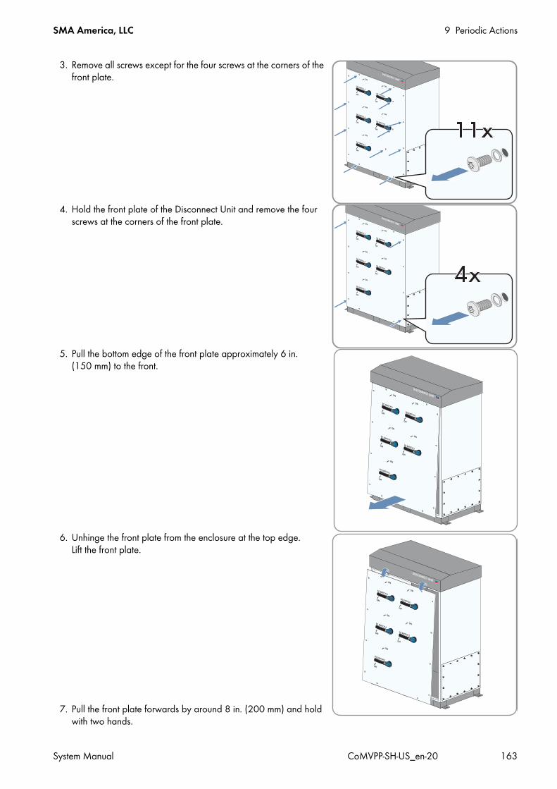
SMA America, LLC 9 Periodic Actions
System Manual CoMVPP-SH-US_en-20 163
3. Remove all screws except for the four screws at the corners of the front plate.
4. Hold the front plate of the Disconnect Unit and remove the four screws at the corners of the front plate.
5. Pull the bottom edge of the front plate approximately 6 in. (150 mm) to the front.
6. Unhinge the front plate from the enclosure at the top edge. Lift the front plate.
7. Pull the front plate forwards by around 8 in. (200 mm) and hold with two hands.

9 Periodic Actions SMA America, LLC
164 CoMVPP-SH-US_en-20 System Manual
8. Remove the grounding strap from the bottom left corner of the front plate.
9. Remove the front plate.
9.1.3.2 Mounting the Front Plate
Requirement: The MV Power Platform must be disconnected (see Section 5, page 62).
Procedure:1. Turn all switch levers on the removed front plate to the OFF position.2. Attach the terminal brackets of the enclosure from the sides to the
correct position between 11.75 in. and 1 ft. 3.75 in. (300 mm to 400 mm).
3. Secure the front plate using two hands and hold it against the front of the Disconnect Unit. The distance between the Disconnect Unit and the front plate must be approximately 8 in. (200 mm).
Risk of injury due to heavy and bulky front plate of the Disconnect UnitThe front plate of the Disconnect Unit is heavy and bulky. If you try to mount and move the front plate on your own, you run a risk of limbs being crushed.
• Note the weight of the front plate of the Disconnect Unit.• Two persons are needed to move the front plate of the Disconnect Unit.• Ensure that one person is holding the front plate at all times when the other person is working on it.
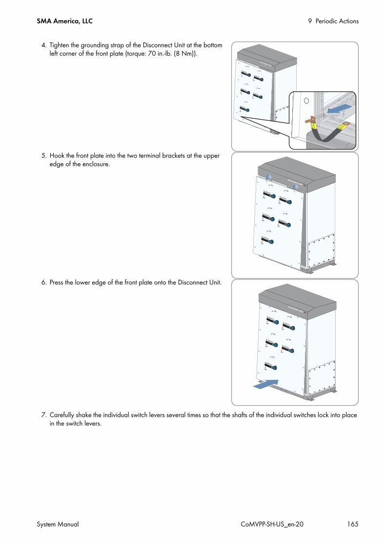
SMA America, LLC 9 Periodic Actions
System Manual CoMVPP-SH-US_en-20 165
4. Tighten the grounding strap of the Disconnect Unit at the bottom left corner of the front plate (torque: 70 in.-lb. (8 Nm)).
5. Hook the front plate into the two terminal brackets at the upper edge of the enclosure.
6. Press the lower edge of the front plate onto the Disconnect Unit.
7. Carefully shake the individual switch levers several times so that the shafts of the individual switches lock into place in the switch levers.
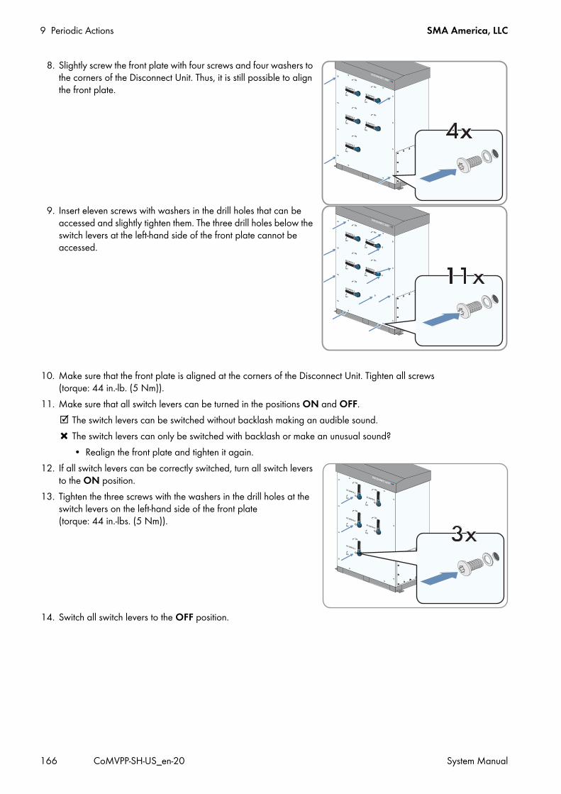
9 Periodic Actions SMA America, LLC
166 CoMVPP-SH-US_en-20 System Manual
8. Slightly screw the front plate with four screws and four washers to the corners of the Disconnect Unit. Thus, it is still possible to align the front plate.
9. Insert eleven screws with washers in the drill holes that can be accessed and slightly tighten them. The three drill holes below the switch levers at the left-hand side of the front plate cannot be accessed.
10. Make sure that the front plate is aligned at the corners of the Disconnect Unit. Tighten all screws (torque: 44 in.-lb. (5 Nm)).
11. Make sure that all switch levers can be turned in the positions ON and OFF. The switch levers can be switched without backlash making an audible sound. The switch levers can only be switched with backlash or make an unusual sound?
• Realign the front plate and tighten it again.12. If all switch levers can be correctly switched, turn all switch levers
to the ON position.13. Tighten the three screws with the washers in the drill holes at the
switch levers on the left-hand side of the front plate (torque: 44 in.-lbs. (5 Nm)).
14. Switch all switch levers to the OFF position.

SMA America, LLC 9 Periodic Actions
System Manual CoMVPP-SH-US_en-20 167
9.2 Cable Entry9.2.1 Inserting the Cables through the Base Plates
Procedure:1. Cut the conduits to length to the base plates.2. Attach the conduit fittings to the conduits.3. Lead the conduit fittings of the conduits through the base plate.4. Lead the cables through the conduits into the prepared holes of the base plate.5. Mount the base plates (torque: 17 ft.-lb. (23 Nm)). 6. Secure the conduit fittings of the conduits to the base plates using counter nuts.7. Seal all conduit fittings and conduits. This will prevent dust and moisture intrusion.8. If the installation is not to be continued on the same day, the device must be closed. Panels must also be mounted in
the inverters (see Section 9.1.2.2, page 161).
Damage to the devices due to moisture penetrationMoisture and water penetration can damage the devices of the MV Power Platform or impair their functionality.
• The openings must not be too large so that they can be sealed easily.• Use fittings and conduits to seal all openings as required by the National Electrical Code® ANSI/NFPA 70.

9 Periodic Actions SMA America, LLC
168 CoMVPP-SH-US_en-20 System Manual
9.3 Bolted Connections9.3.1 Connecting the Grounding Cable and DC Cable with One Two-Hole
Terminal LugWhen carrying out the individual actions, always observe the safety precautions described in the Section 4.1 "Safety during Installation".
Overview of the Connection with One Two-Hole Terminal Lug
Figure 57: Assembly of the connection with one two-hole terminal lug
Requirements: All cable requirements must be complied with. The cables must be routed into the corresponding device via conduits. The panels in the connection area of the inverter must be removed (see Section 9.1.2.1, page 161). The protective covers in the connection area of the inverter must be removed (see Section 9.1.2.1, page 161).
Position DesignationA Nut M12B Spring washerC Fender washerD Copper barE Tin-plated two-hole terminal lugF Screw M12

SMA America, LLC 9 Periodic Actions
System Manual CoMVPP-SH-US_en-20 169
Additionally required mounting material (not included in the scope of delivery): Clean cloth Ethanol cleaning agent Non-woven abrasive
Procedure:1. Strip the cable insulation.2. Fit the cables with terminal lugs.3. Clean the contact surfaces using a clean cloth and ethanol cleaning agent.4. Clean the contact surfaces of the areas that are not tin-plated with the non-woven abrasive until they have a light
metallic sheen. Ensure that the coated contact surfaces are not damaged.5. Remove metal dust with a clean cloth and ethanol cleaning agent.6. Do not touch the contact surfaces after cleaning.7. Connect the cables with the specified torque in accordance with the circuit diagram. Only use the screws, nuts and
washers included in the scope of delivery and make sure that the screw heads always point forwards.
8. Secure the cables at the cable support rails.9. If other cables are not installed immediately afterwards, mount the front panel of the Disconnect Unit
(see Section 13.3.2).
Type of terminal lug TorqueTin-plated aluminum terminal lug 27.5 ft.-lb. (37 Nm)Tin-plated copper terminal lug 44.5 ft.-lb. (60 Nm)Aluminum terminal lug on tin-plated aluminum bar 27.5 ft.-lbs. (37 Nm)Copper terminal lug on tin-plated aluminum bar 27.5 ft.-lbs. (37 Nm)

9 Periodic Actions SMA America, LLC
170 CoMVPP-SH-US_en-20 System Manual
9.3.2 Connecting the Grounding Cable and DC Cables with Two Two-Hole Terminal Lugs
Connection Overview with Two Two-Hole Terminal Lugs
Figure 58: Design of the connection with two two-hole terminal lugs
Requirements: All cable requirements must be complied with. The cables must be routed into the corresponding device via conduits. The panels in the connection area of the inverter must be removed (see Section 9.1.2.1, page 161). The protective covers in the connection area of the inverters must be removed (see Section 9.1.2.1, page 161).
Additionally required mounting material (not included in the scope of delivery): Clean cloth Ethanol cleaning agent Non-woven abrasive
Position DesignationA Nut M12B Spring washerC Fender washerD Tin-plated two-hole terminal lugE Copper barF Screw M12

SMA America, LLC 9 Periodic Actions
System Manual CoMVPP-SH-US_en-20 171
Procedure:1. Strip the cable insulation.2. Fit the cables with terminal lugs.3. Clean the contact surfaces using a clean cloth and ethanol cleaning agent.4. Clean the contact surfaces of the areas that are not tin-plated with the non-woven abrasive until they have a light
metallic sheen. Ensure that the coated contact surfaces are not damaged.5. Remove metal dust with a clean cloth and ethanol cleaning agent.6. Do not touch the contact surfaces after cleaning.7. Connect the cables with the specified torque in accordance with the circuit diagram. Only use the screws and nuts
included in the scope of delivery.
8. Secure the cables at the cable support rails.9. If other cables are not installed immediately afterwards, mount the front panel of the Disconnect Unit
(see Section 9.1.3.2, page 164).
9.4 Clamp Connections9.4.1 Connecting the Cables to the Spring-Cage Terminals
1. Das Kabel 2.4 in. (60 mm) abmanteln. 2. Strip 0.2 in. (5 mm) off the conductor insulation.
3. Connect the cable in accordance with the circuit diagram.
• Insert the screwdriver into the square-shaped opening next to the terminal. This will unlock the terminal.
• Insert the insulated conductors of the cable in the terminal in accordance with the circuit diagram.
Type of terminal lug TorqueTin-plated aluminum terminal lug 27.5 ft.-lb. (37 Nm)Tin-plated copper terminal lug 44.5 ft.-lb. (60 Nm)

9 Periodic Actions SMA America, LLC
172 CoMVPP-SH-US_en-20 System Manual
• Pull the screwdriver out of the terminal.
9.4.2 Connecting the Cable Shield Using a Shield Clamping SaddleIf the MV Power Platform is not fitted with an Auxiliary Services Rack, you will need to connect the data and supply cables in the inverter. You must connect the cable shields to the shield clamping saddles.
Cable requirement: The cable used must be shielded.
Requirement: No voltage must be present on the MV Power Platform.
Procedure:1. Lead the cable into the interface cabinet (see Section 9.4.1, page 171).2. Connect the cable in accordance with the circuit diagram.3. Remove the shield clamping saddle from the busbar.4. Position the shield clamping saddle on the stripped cable until it
clicks into place, and fasten hand-tight. Make sure that the shield clamping saddle is in contact with the cable shield.
5. Attach the cable to the cable support rail using a cable tie. This ensures that the cable cannot be pulled out.
SMA America, LLC 9 Periodic Actions
System Manual CoMVPP-SH-US_en-20 173
9.5 Settings on the User Interface of the Inverter9.5.1 Logging Into the User InterfaceThe default password for the user groups "Installer" and "User" is "sma".
Requirement: JavaScript must be enabled in your Internet browser (e.g. Internet Explorer).
Procedure:1. Connect the laptop to the service interface of the inverter.2. Start your Internet browser.3. Enter the IP address of the inverter into the address bar and press the enter key.4. Select the desired language in the Language field.5. Enter the password in the Password field.6. Select the button [Login].
9.5.2 Logging Out of the User InterfaceAlways log out from the user interface when you have finished your work. If you only close the Internet browser, you will not be logged out of the user interface.Procedure:
• Select the button [Logout].
9.5.3 Accessing the Parameter Overview1. Log into the user interface as an installer (see Section 9.5.1, page 173).2. Select Data > Devices.3. Select the desired device.4. Select the tab Parameters.
9.5.4 Saving Parameter ChangesRequirement: You must be logged into the user interface (see Section 9.5.1, page 173).
Procedure:1. Change the respective parameter via the Value field.2. To adopt this value for all devices of the same type and with the same firmware version, activate the box
Save for all devices of this device type. 3. Select the button [Save].
The communication interface adjusts the required value on the device(s). When the value is changed, the message "### Parameter change finished ###" appears.
4. Select the button [OK].
Identical passwords for the user groupsIf your "User" password is the same as your "Installer" password, you will automatically be logged in as an installer.
• Change the default passwords for the user groups after you log in for the first time (see Section 6.2.5, page 81).

9 Periodic Actions SMA America, LLC
174 CoMVPP-SH-US_en-20 System Manual
9.6 Entering the Installer Password via Touch Display
Procedure:1. Select .2. Select .3. Enter the installer password. Use the keypad to do this.4. Confirm entry by selecting .
The symbol appears in the status info line. The status info line does not show the symbol?
An incorrect password was entered.• Enter the password again.
Installer accessThe "Installer" access level is activated by entering the installer password.The access level will be reset after 15 minutes.
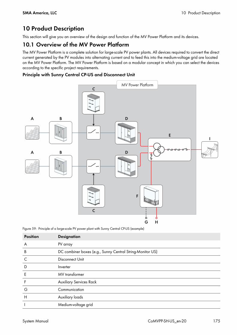
SMA America, LLC 10 Product Description
System Manual CoMVPP-SH-US_en-20 175
10 Product DescriptionThis section will give you an overview of the design and function of the MV Power Platform and its devices.10.1 Overview of the MV Power PlatformThe MV Power Platform is a complete solution for large-scale PV power plants. All devices required to convert the direct current generated by the PV modules into alternating current and to feed this into the medium-voltage grid are located on the MV Power Platform. The MV Power Platform is based on a modular concept in which you can select the devices according to the specific project requirements.Principle with Sunny Central CP-US and Disconnect Unit
Figure 59: Principle of a large-scale PV power plant with Sunny Central CP-US (example)
Position DesignationA PV arrayB DC combiner boxes (e.g., Sunny Central String-Monitor US)C Disconnect UnitD InverterE MV transformerF Auxiliary Services RackG CommunicationH Auxiliary loadsI Medium-voltage grid

10 Product Description SMA America, LLC
176 CoMVPP-SH-US_en-20 System Manual
Principle with Sunny Central CP-US without Disconnect Unit
Figure 60: Principle of a large-scale PV power plant with Sunny Central CP-US (example)
10.2 Design of the MV Power PlatformSubject to the individual order, the MV Power Platform is equipped with two inverters, two Disconnect Units, one Auxiliary Services Rack and one MV transformer. The MV Power Platform is a fully integrated, turnkey solution which is cabled and tested at the factory. The MV Power Platform can be erected on concrete piers, a concrete pad, grade beam or on a compacted gravel bed, and is suitable for installation in all regions of North America.Underneath each individual device on the MV Power Platform there are removable base plates to which conduits can be mounted. The conduits protect the cables when they are inserted into the devices.When connecting the communication and carrying out maintenance work, it is important to distinguish between inverter 1 and inverter 2.
Position DesignationA PV arrayB DC combiner boxes (e.g., Sunny Central String-Monitor US)C InvertersD MV transformerE Auxiliary Services RackF CommunicationG Auxiliary loadsH Medium-voltage grid
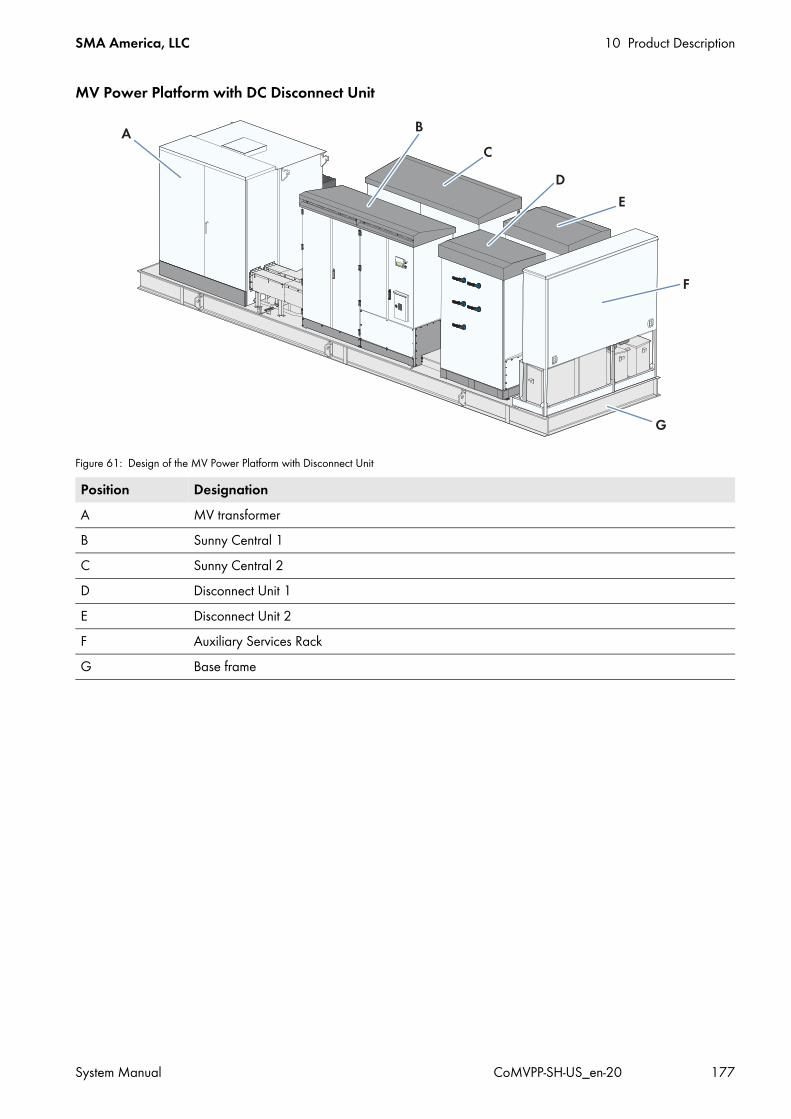
SMA America, LLC 10 Product Description
System Manual CoMVPP-SH-US_en-20 177
MV Power Platform with DC Disconnect Unit
Figure 61: Design of the MV Power Platform with Disconnect Unit
Position DesignationA MV transformerB Sunny Central 1C Sunny Central 2D Disconnect Unit 1E Disconnect Unit 2F Auxiliary Services RackG Base frame
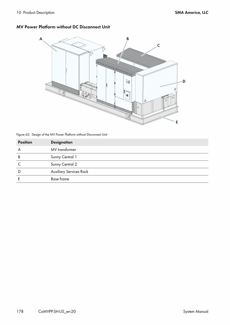
10 Product Description SMA America, LLC
178 CoMVPP-SH-US_en-20 System Manual
MV Power Platform without DC Disconnect Unit
Figure 62: Design of the MV Power Platform without Disconnect Unit
Position DesignationA MV transformerB Sunny Central 1C Sunny Central 2D Auxiliary Services RackE Base frame
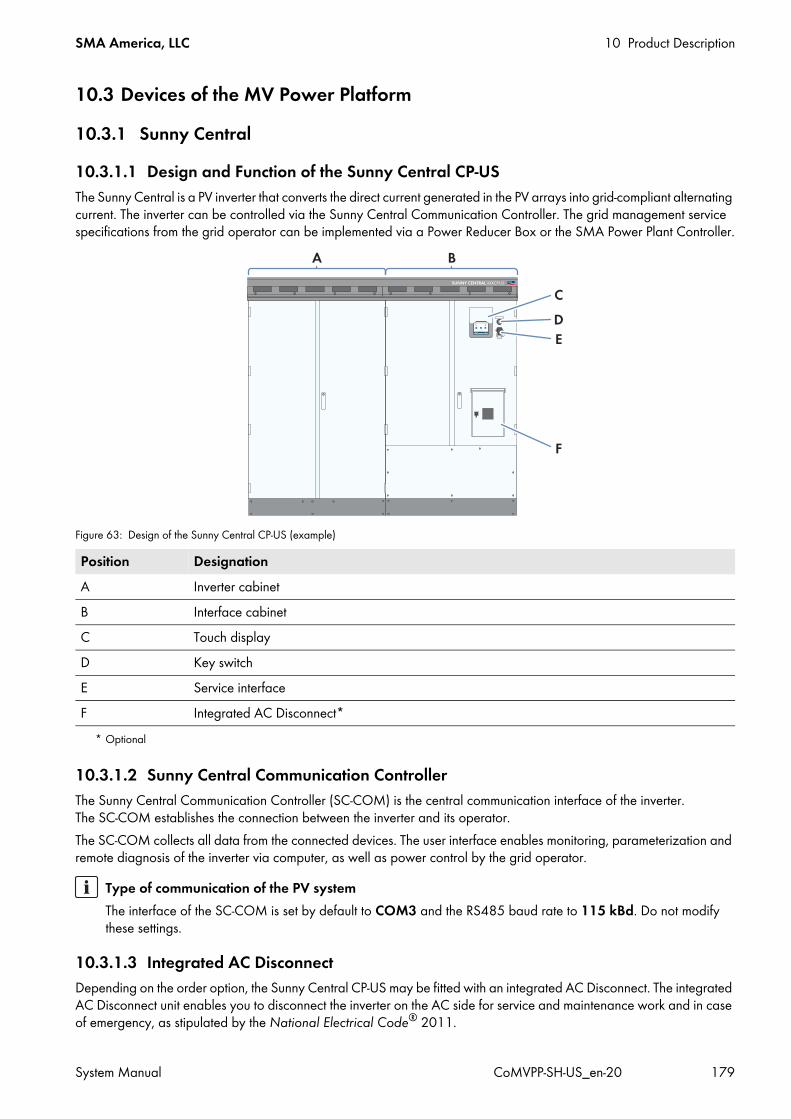
SMA America, LLC 10 Product Description
System Manual CoMVPP-SH-US_en-20 179
10.3 Devices of the MV Power Platform10.3.1 Sunny Central10.3.1.1 Design and Function of the Sunny Central CP-USThe Sunny Central is a PV inverter that converts the direct current generated in the PV arrays into grid-compliant alternating current. The inverter can be controlled via the Sunny Central Communication Controller. The grid management service specifications from the grid operator can be implemented via a Power Reducer Box or the SMA Power Plant Controller.
Figure 63: Design of the Sunny Central CP-US (example)
10.3.1.2 Sunny Central Communication ControllerThe Sunny Central Communication Controller (SC-COM) is the central communication interface of the inverter. The SC-COM establishes the connection between the inverter and its operator.The SC-COM collects all data from the connected devices. The user interface enables monitoring, parameterization and remote diagnosis of the inverter via computer, as well as power control by the grid operator.
10.3.1.3 Integrated AC DisconnectDepending on the order option, the Sunny Central CP-US may be fitted with an integrated AC Disconnect. The integrated AC Disconnect unit enables you to disconnect the inverter on the AC side for service and maintenance work and in case of emergency, as stipulated by the National Electrical Code® 2011.
Position DesignationA Inverter cabinetB Interface cabinetC Touch displayD Key switchE Service interfaceF Integrated AC Disconnect*
* Optional
Type of communication of the PV systemThe interface of the SC-COM is set by default to COM3 and the RS485 baud rate to 115 kBd. Do not modify these settings.

10 Product Description SMA America, LLC
180 CoMVPP-SH-US_en-20 System Manual
10.3.2 Disconnect UnitThe Disconnect Unit is used to disconnect the MV Power Platform from the PV arrays for service and maintenance work and in case of emergency, as stipulated by the National Electrical Code® 2011. The internal cabling of the Disconnect Unit 1 and Disconnect Unit 2 differs due to the arrangement on the MV Power Platform.
Figure 64: Disconnect Unit
Position DesignationA Switch for the DC inputs

SMA America, LLC 10 Product Description
System Manual CoMVPP-SH-US_en-20 181
10.3.3 MV TransformerThe MV transformer is the link between the inverters and the medium-voltage grid. The MV transformer is equipped with a disconnection device on the low and medium-voltage side, enabling simple and safe disconnection. You can find further information on the MV transformer in the Technical Description document "SC_CoMVPP 3w Trafo-TD-EN-10" at www.SMA-Solar.com.
Figure 65: Design of the MV transformer
Position DesignationA Liquid level gauge and alarm contactsB Pressure relief valveC Vacuum switch with alarm contactsD Pressure switch with alarm contactsE Liquid temperature gauge with alarm contactsF Vacuum pressure gaugeG Fuse holders / fuses, oil immersed expulsion (for MV < 23 kV)H Tap changerI Primary (MV) bushingsK Secondary (LV) bushingsL Fuse block (for LV distribution)M Grounding busbarsN Drain valve in lockable enclosureO Alarm contact terminalsP Medium-voltage load-break switch (lockable)

10 Product Description SMA America, LLC
182 CoMVPP-SH-US_en-20 System Manual
10.3.4 Auxiliary Services RackThe Auxiliary Services Rack enables the connection of supply voltage, communication and control systems. The disconnect units on the boxes enable simple and safe disconnection of the supply voltages from the MV Power Platform or, if configured, the array tracker motor circuits. The Auxiliary Services Rack is protected from solar irradiation by a sun shield. The push stick to open the sun shield is located at the bottom of the Auxiliary Services Rack in front of the transformers.Depending on the specific order, the Auxiliary Services Rack is equipped with various devices:
Figure 66: Auxiliary Services Rack
Position Designation DescriptionA Customer-specific box This space is reserved for a customer-specific box in which additional devices
may be installed.B Brown Power Box Fusing of the inverter when operated with an external supply voltageC Inverter Box Supply voltage for Sunny Central CP-USD Outlets Two outlets each with 120 V and 250 W for connecting external devicesE Pull Box All cables for supply voltage, communication and control systems to be
connected in the Main Box or Tracker Box must be routed into the Auxiliary Service Rack through the interface gland plate of the Pull Box.
F Generator inlet The Tracker Box is equipped with a generator inlet for the external voltage supply of the solar trackers.
G Tracker Box Supply voltage of the solar trackers with up to eight outputs and max. 30 kVAH Main Box Terminals for the supply voltage of 120 V devices, communication and control
systems
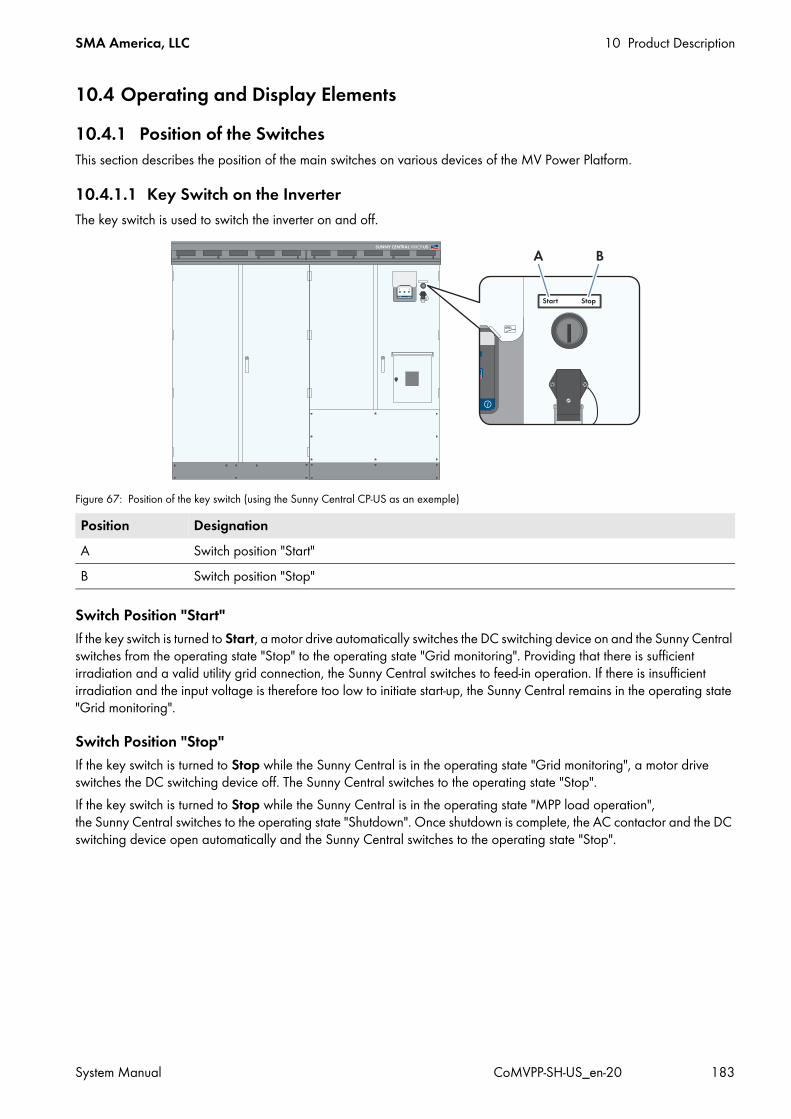
SMA America, LLC 10 Product Description
System Manual CoMVPP-SH-US_en-20 183
10.4 Operating and Display Elements10.4.1 Position of the SwitchesThis section describes the position of the main switches on various devices of the MV Power Platform.
10.4.1.1 Key Switch on the InverterThe key switch is used to switch the inverter on and off.
Figure 67: Position of the key switch (using the Sunny Central CP-US as an exemple)
Switch Position "Start"If the key switch is turned to Start, a motor drive automatically switches the DC switching device on and the Sunny Central switches from the operating state "Stop" to the operating state "Grid monitoring". Providing that there is sufficient irradiation and a valid utility grid connection, the Sunny Central switches to feed-in operation. If there is insufficient irradiation and the input voltage is therefore too low to initiate start-up, the Sunny Central remains in the operating state "Grid monitoring".
Switch Position "Stop"If the key switch is turned to Stop while the Sunny Central is in the operating state "Grid monitoring", a motor drive switches the DC switching device off. The Sunny Central switches to the operating state "Stop".If the key switch is turned to Stop while the Sunny Central is in the operating state "MPP load operation", the Sunny Central switches to the operating state "Shutdown". Once shutdown is complete, the AC contactor and the DC switching device open automatically and the Sunny Central switches to the operating state "Stop".
Position DesignationA Switch position "Start"B Switch position "Stop"
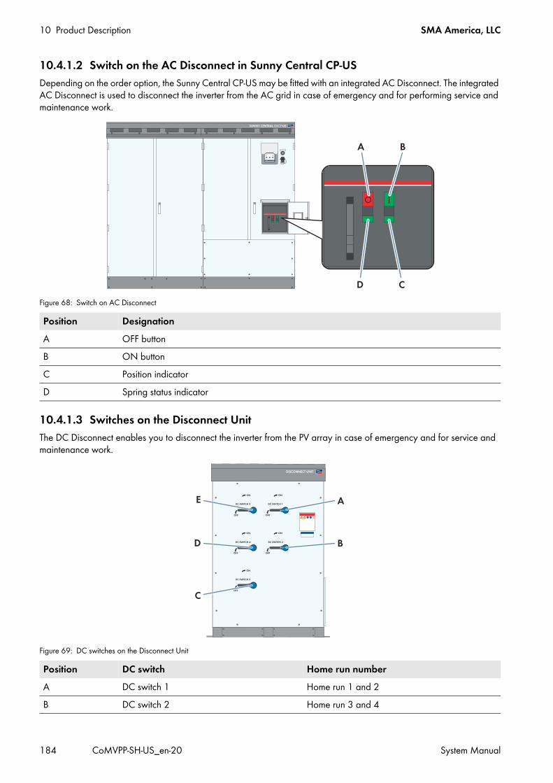
10 Product Description SMA America, LLC
184 CoMVPP-SH-US_en-20 System Manual
10.4.1.2 Switch on the AC Disconnect in Sunny Central CP-USDepending on the order option, the Sunny Central CP-US may be fitted with an integrated AC Disconnect. The integrated AC Disconnect is used to disconnect the inverter from the AC grid in case of emergency and for performing service and maintenance work.
Figure 68: Switch on AC Disconnect
10.4.1.3 Switches on the Disconnect UnitThe DC Disconnect enables you to disconnect the inverter from the PV array in case of emergency and for service and maintenance work.
Figure 69: DC switches on the Disconnect Unit
Position DesignationA OFF buttonB ON buttonC Position indicatorD Spring status indicator
Position DC switch Home run numberA DC switch 1 Home run 1 and 2B DC switch 2 Home run 3 and 4

SMA America, LLC 10 Product Description
System Manual CoMVPP-SH-US_en-20 185
10.4.1.4 Switches on the Auxiliary Services RackUsing the switches on the optional Auxiliary Services Rack, you can disconnect the supply voltage of various devices on the MV Power Platform.
Figure 70: Connection points on the Auxiliary Services Rack
C DC switch 3 Home run 9D DC switch 4 Home run 7 and 8E DC switch 5 Home run 5 and 6
Position Designation ExplanationA Switch of the Inverter Box* Disconnects the supply voltage from the inverterB Switch of the Brown Power Box* Disconnects the MV Power Platform from the external supply voltageC Switch of the Main Box Disconnects all 208 V / 120 V components from the
Auxiliary Services Rack, e.g. communication devices, outlet and customer-specific boxes.
D Switch of the Tracker Box** optional
Disconnects the voltage supply to the external tracker motors
Position DC switch Home run number

10 Product Description SMA America, LLC
186 CoMVPP-SH-US_en-20 System Manual
10.4.1.5 Switches on the MV TransformerThe medium-voltage load-break switch enables the operator to disconnect the MV Power Platform from the medium-voltage grid.
10.4.2 Touch Display of the Sunny Central10.4.2.1 Description of the Touch DisplayThe touch display of the Sunny Central is used to display instantaneous values and parameter settings. The touch display is fitted with a cover to protect it from weather influences. This cover can be pushed up to read the display.The display area is activated by touching the touch display. Tapping the symbols on the touch display activates the corresponding function. If the touch display is not touched for five minutes, it will switch off.You cannot set any inverter parameters on the touch display, but only configure display settings such as language, time, brightness (see Section 6.1, page 79). You can also display the operating data (see Section 6.4.1, page 90).The touch display is divided into three areas.
Figure 71: Touch display areas
Position DesignationA Medium voltage load-break switch
Object DesignationA Status info line

SMA America, LLC 10 Product Description
System Manual CoMVPP-SH-US_en-20 187
10.4.2.2 Explanation of Symbols
Status Info Line
Figure 72: Structure of the status info line
Information Area - Main MenuYou can access the following sub-menus and screens from the main menu:
B Information areaC Navigation line
Object DesignationA Number of the active menuB Symbol indicating whether the inverter is currently password-protected or is free for configurationC Date and time display
Symbol Designation ExplanationE-today line graph Select this symbol to see the energy fed-in on the current day in kWh.
Bar chart Select this symbol to see the energy fed in over the last 14 days in kWh.
DC side Select this symbol to see the following instantaneous values:• PV power in W• Insulation resistance in Ω• PV current in A• PV voltage in V
The page which opens also contains the symbol. Select this symbol to see the diagrams on the sub-menu level.
Object Designation

10 Product Description SMA America, LLC
188 CoMVPP-SH-US_en-20 System Manual
Switch on DC or AC side closed
If you see this symbol between the "DC side" symbol and the "Inverter data" symbol, the DC contactor is closed.If you see this symbol between the "Inverter data" symbol and the "AC side" symbol, the AC contactor is closed.
Switch on DC or AC side open
If you see this symbol between the "DC side" symbol and the "Inverter data" symbol, the DC contactor is open.If you see this symbol between the "Inverter data" symbol and the "AC side" symbol, the AC contactor is open.
Status of switches on DC or AC side unknown
If you see this symbol between the "DC side" symbol and the "Inverter data" symbol, the switch status of the DC contactor is not known.If you see this symbol between the "Inverter data" symbol and the "AC side" symbol, the switch status of the AC contactor is not known.
Inverter data Select this symbol to see the following data:• Device type• Operating state• Symbol for utility grid menu• Symbol for temperature display• Symbol for fan display
AC side Select this symbol to see the following instantaneous values:• Active power in W• Reactive power in VAr• Power frequency in Hz• Alternating current in A• AC voltage in V
Grid Select this symbol to see the following data on the first page of the menu:
• Active procedure for active power limitation (see Section 10.8.1, page 207)
• Target active power in kW• Actual active power in kW
Select to see the following data on the second page of the menu:• Active procedure for reactive power setpoint (see Section 10.8.4,
page 210)• Target reactive power in VAr• Target displacement power factor cos phi• Target excitation type of the displacement power factor• Actual reactive power in VAr• Actual displacement power factor cos phi• Actual excitation type of the displacement power factor
Symbol Designation Explanation
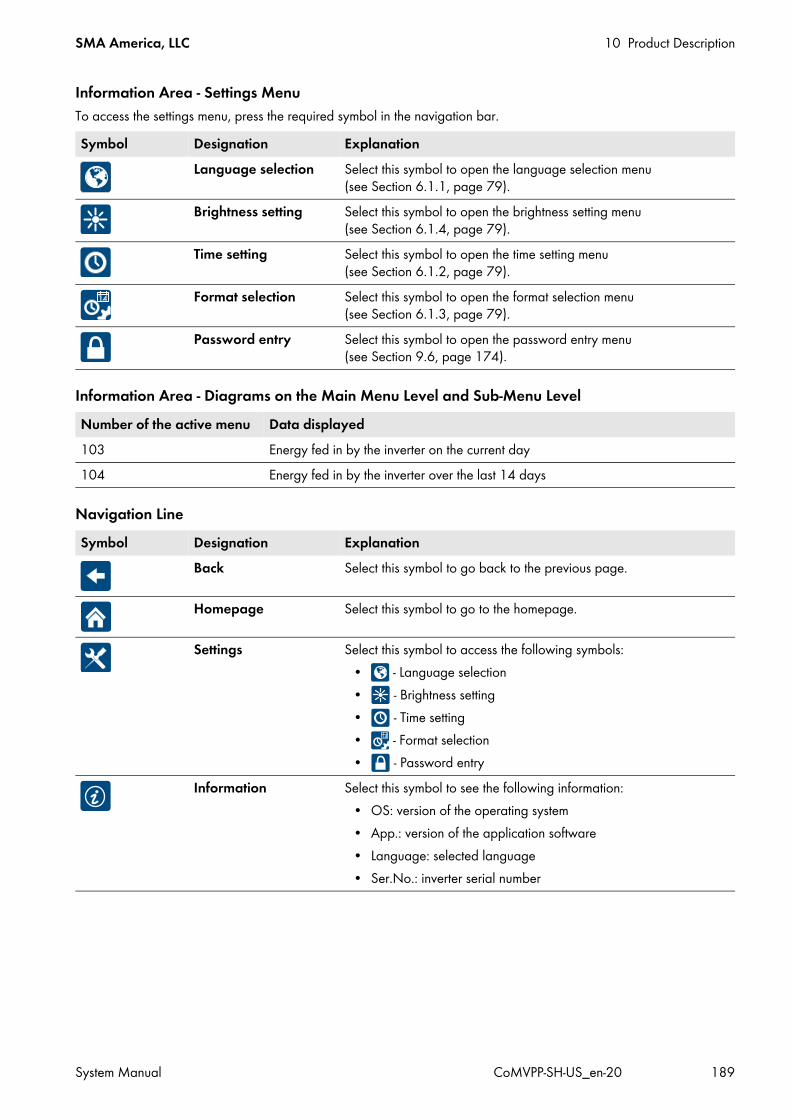
SMA America, LLC 10 Product Description
System Manual CoMVPP-SH-US_en-20 189
Information Area - Settings MenuTo access the settings menu, press the required symbol in the navigation bar.
Information Area - Diagrams on the Main Menu Level and Sub-Menu Level
Navigation Line
Symbol Designation ExplanationLanguage selection Select this symbol to open the language selection menu
(see Section 6.1.1, page 79).Brightness setting Select this symbol to open the brightness setting menu
(see Section 6.1.4, page 79).Time setting Select this symbol to open the time setting menu
(see Section 6.1.2, page 79).Format selection Select this symbol to open the format selection menu
(see Section 6.1.3, page 79).Password entry Select this symbol to open the password entry menu
(see Section 9.6, page 174).
Number of the active menu Data displayed103 Energy fed in by the inverter on the current day104 Energy fed in by the inverter over the last 14 days
Symbol Designation ExplanationBack Select this symbol to go back to the previous page.
Homepage Select this symbol to go to the homepage.
Settings Select this symbol to access the following symbols:• - Language selection• - Brightness setting• - Time setting• - Format selection• - Password entry
Information Select this symbol to see the following information:• OS: version of the operating system• App.: version of the application software• Language: selected language• Ser.No.: inverter serial number

10 Product Description SMA America, LLC
190 CoMVPP-SH-US_en-20 System Manual
10.4.3 User Interface of the Sunny Central10.4.3.1 StructureVia the user interface, you can set the communication of your PV system devices, configure the inverter parameters and read off error messages and operating data.
Figure 73: Structure of the user interface (example)
Errors This symbol appears when an error occurs.The symbol is displayed once in the symbol of the PV system section where the error has occurred and again in the menu bar. Select this symbol from the menu bar to see the following data:
• ErrNo: error number• TmsRmg: time until reconnection• Msg: error message• Dsc: corrective measure
Service The "telephone" symbol appears when you are advised to contact the SMA Service Line.The "tool" symbol appears when you are advised to have the error corrected by your installer. Contact your installer.
Position DesignationA Structure view or device view(see Section 10.4.3.2, page 191)B Status barC Logout buttonD Navigation barE Content area
Symbol Designation Explanation
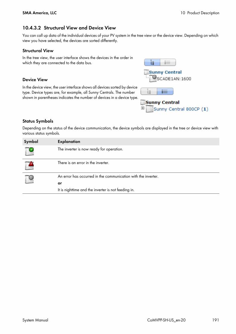
SMA America, LLC 10 Product Description
System Manual CoMVPP-SH-US_en-20 191
10.4.3.2 Structural View and Device ViewYou can call up data of the individual devices of your PV system in the tree view or the device view. Depending on which view you have selected, the devices are sorted differently.
Structural ViewIn the tree view, the user interface shows the devices in the order in which they are connected to the data bus.
Device ViewIn the device view, the user interface shows all devices sorted by device type. Device types are, for example, all Sunny Centrals. The number shown in parentheses indicates the number of devices in a device type.
Status SymbolsDepending on the status of the device communication, the device symbols are displayed in the tree or device view with various status symbols.Symbol Explanation
The inverter is now ready for operation.
There is an error in the inverter.
An error has occurred in the communication with the inverter.orIt is nighttime and the inverter is not feeding in.

10 Product Description SMA America, LLC
192 CoMVPP-SH-US_en-20 System Manual
10.4.4 Insulation Monitoring DeviceDepending on the configuration, an insulation monitoring device monitors the insulation resistance of the PV plant in ungrounded utility grids.In the operating state "MPP load operation", the insulation resistance of the entire system, from the PV modules to the medium-voltage transformer, will be measured.If the inverter is in the "Grid monitoring" operating state, only the insulation resistance from the PV modules to the inverter is measured.
Figure 74: Insulation monitoring device in the inverterA measuring circuit and a relay with a change-over contact are integrated in the insulation monitoring device.The insulation monitoring device is connected between the PV voltage and the PE protective conductor.The contacts of the relay are routed to the customer connecting terminal plate and can be used by the customer to trip a signal light or horn. The characteristics of the relay are indicated in the circuit diagram.If the insulation resistance falls below the warning threshold specified in the RisoCtlWarn parameter, the measuring circuit closes and the LED ALARM1 on the insulation monitoring device lights up. The error message 3601‒ Warning insulation error is generated by the inverter. Simultaneously, the insulation monitoring device activates the relay with changeover contact. This relay is installed in the inverter. If the insulation resistance falls below the error threshold (1 kΩ), an insulation error has occurred and the LEDs ALARM1 and ALARM2 on the insulation monitoring device light up. In this case, the operating behavior of the inverter can be set via parameters:
• If the parameter IsoErrIgn is set to Off, the measuring circuit issues a disturbance when the insulation resistance falls below the error threshold, the inverter switches off and issues the error message 3501 - Insulation error. The LEDs ALARM1 and ALARM2 are glowing.
• If the parameter IsoErrIgn is set to On, the error message from the measuring circuit is ignored when the insulation resistance falls below the error threshold. The inverter continues to feed into the grid and generates the error message 3504 ‒ Insulation error ignored.
If the parameter IsoErrIgn is set to Run and the insulation resistance falls below the error threshold, the error message from the measuring circuit will only be ignored if the inverter is in feed-in operation. In feed-in operation, the inverter continues to feed in and issues the error message 3504 ‒ Insulation error ignored. If the insulation resistance falls below the error threshold in another operating state, the error is not ignored and the inverter does not go into feed-in operation. The error message 3501 ‒ Insulation error appears on the touch display. The LEDs ALARM1 and ALARM2 are glowing.Type of insulation monitoring device usedThe insulation monitoring device used is the A-ISOMETER iso-PV1685 device supplied by Bender GmbH & Co. KG.

SMA America, LLC 10 Product Description
System Manual CoMVPP-SH-US_en-20 193
10.4.5 LEDs of the SC-COMIf there is a disturbance in the internal communication, you can determine the status of the SC-COM via the LEDs. To do this, you will have to open the inverter.
10.4.5.1 LEDs on the Enclosure
Figure 75: LEDs on the enclosure of the SC-COM
Name of LED Status ExplanationPOWER Is glowing green The SC-COM has voltage supply.
Off The SC-COM has no voltage supply.HDD1 Is flashing green Read or write access to system driveHDD2 Is flashing green Read or write access to the internal memorySDHC Is flashing green Read or write access to the SD memory cardH1 Is flashing green The SC-COM is transmitting data to Sunny Portal/the FTP server.
Is glowing green The most recent data transmission to Sunny Portal/the FTP server was successful.
Is glowing red The most recent data transmission to Sunny Portal/the FTP server has failed.Off Data transmission to Sunny Portal/the FTP server is disabled.
H2 Is flashing green The SC-COM is communicating with the devices connected within the system.Is glowing green Internal communication has taken place in the last five minutes.Is glowing red A disturbance has occurred in the internal communication.Off No internal communication for more than five minutes.

10 Product Description SMA America, LLC
194 CoMVPP-SH-US_en-20 System Manual
10.4.5.2 LEDs on the Network TerminalIf the SC-COM is connected with a patch cable, you can determine the connection status from the LEDs of the network terminal.
Figure 76: LEDs on the network terminal
10.4.5.3 LEDs on the Optical Fiber TerminalsDepending on the order option, the SC-COM may be equipped with optical fibers.If the optical fibers are connected to the splice box of the inverter, the status of the connection will be indicated by the LEDs of the SC-COM.
H3 Is flashing red The SC-COM is starting up.Is glowing red An error has occurred in the SC-COM.Is glowing green The SC-COM is ready for use.
H4 Is glowing green An internal memory is available and it is less than 90% full.Is glowing red The internal memory is full. The oldest data will be overwritten.Is flashing red The internal memory is 90% full.
H5 Is glowing green An SD memory card is available and it is less than 90% full.Is glowing red The SD memory card is full.Is flashing red The SD memory card is 90% full.Off No SD memory card
H6 ‒ Not assignedH7 ‒ Not assignedH8 Is flashing green Application is running.
Position LED Color Status ExplanationA Speed yellow On Data transfer rate: 100 MBit
Off Data transfer rate: 10 MBitB Link /
Activitygreen On Connection established (link)
Flashing The SC-COM is currently transmitting or receiving data (activity).Off No connection established
Name of LED Status Explanation
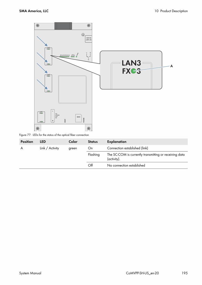
SMA America, LLC 10 Product Description
System Manual CoMVPP-SH-US_en-20 195
Figure 77: LEDs for the status of the optical fiber connection
Position LED Color Status ExplanationA Link / Activity green On Connection established (link)
Flashing The SC-COM is currently transmitting or receiving data (activity).
Off No connection established
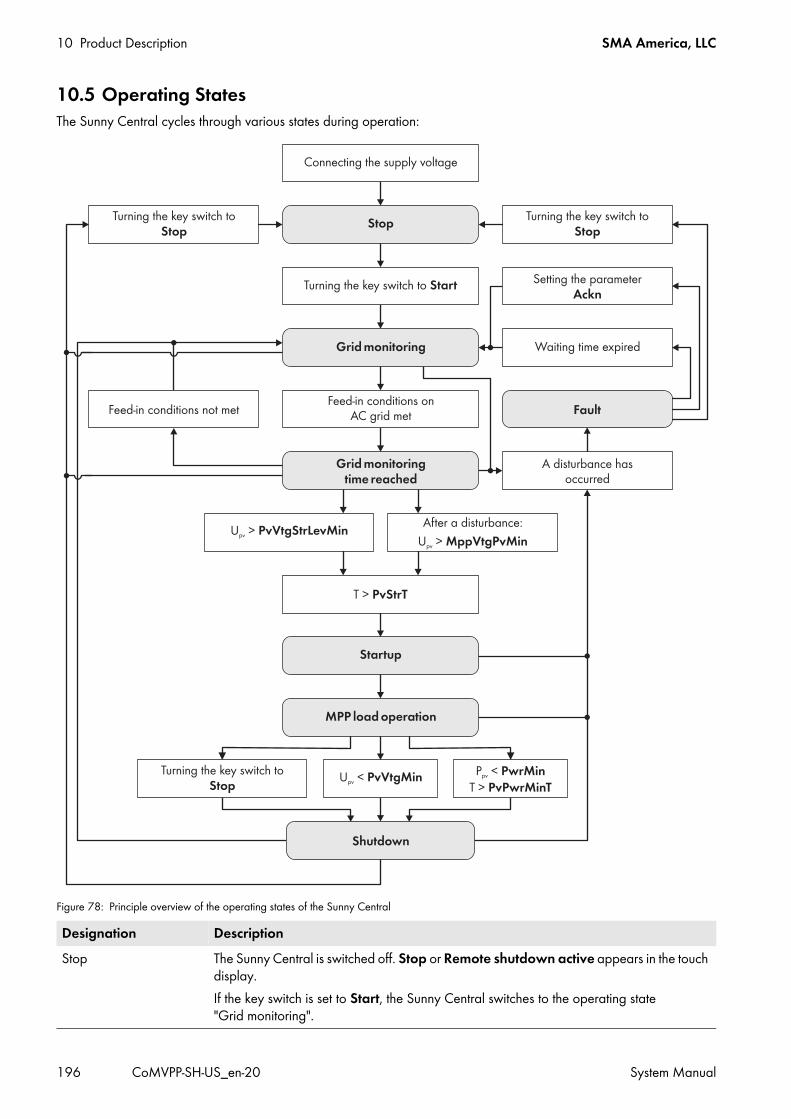
10 Product Description SMA America, LLC
196 CoMVPP-SH-US_en-20 System Manual
10.5 Operating StatesThe Sunny Central cycles through various states during operation:
Figure 78: Principle overview of the operating states of the Sunny Central
Designation DescriptionStop The Sunny Central is switched off. Stop or Remote shutdown active appears in the touch
display.If the key switch is set to Start, the Sunny Central switches to the operating state "Grid monitoring".
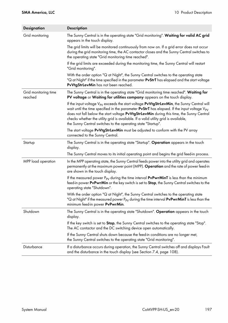
SMA America, LLC 10 Product Description
System Manual CoMVPP-SH-US_en-20 197
Grid monitoring The Sunny Central is in the operating state "Grid monitoring". Waiting for valid AC grid appears in the touch display.The grid limits will be monitored continuously from now on. If a grid error does not occur during the grid monitoring time, the AC contactor closes and the Sunny Central switches to the operating state "Grid monitoring time reached".If the grid limits are exceeded during the monitoring time, the Sunny Central will restart "Grid monitoring".With the order option "Q at Night", the Sunny Central switches to the operating state "Q at Night" if the time specified in the parameter PvStrT has elapsed and the start voltage PvVtgStrLevMin has not been reached.
Grid monitoring time reached
The Sunny Central is in the operating state "Grid monitoring time reached". Waiting for PV voltage or Waiting for utilities company appears on the touch display.If the input voltage VPV exceeds the start voltage PvVtgStrLevMin, the Sunny Central will wait until the time specified in the parameter PvStrT has elapsed. If the input voltage VPV does not fall below the start voltage PvVtgStrLevMin during this time, the Sunny Central checks whether the utility grid is available. If a valid utility grid is available, the Sunny Central switches to the operating state "Startup".The start voltage PvVtgStrLevMin must be adjusted to conform with the PV array connected to the Sunny Central.
Startup The Sunny Central is in the operating state "Startup". Operation appears in the touch display.The Sunny Central moves to its initial operating point and begins the grid feed-in process.
MPP load operation In the MPP operating state, the Sunny Central feeds power into the utility grid and operates permanently at the maximum power point (MPP). Operation and the rate of power feed-in are shown in the touch display.If the measured power PPV during the time interval PvPwrMinT is less than the minimum feed-in power PvPwrMin or the key switch is set to Stop, the Sunny Central switches to the operating state "Shutdown".With the order option "Q at Night", the Sunny Central switches to the operating state "Q at Night" if the measured power PPV during the time interval PvPwrMinT is less than the minimum feed-in power PvPwrMin.
Shutdown The Sunny Central is in the operating state "Shutdown". Operation appears in the touch display.If the key switch is set to Stop, the Sunny Central switches to the operating state "Stop". The AC contactor and the DC switching device open automatically.If the Sunny Central shuts down because the feed-in conditions are no longer met, the Sunny Central switches to the operating state "Grid monitoring".
Disturbance If a disturbance occurs during operation, the Sunny Central switches off and displays Fault and the disturbance in the touch display (see Section 7.4, page 108).
Designation Description
10 Product Description SMA America, LLC
198 CoMVPP-SH-US_en-20 System Manual
10.6 Safety FunctionsThe functions of the MV Power Platform depend on the order.All cables for communication and control are connected in the Auxiliary Services Rack. If there is no Auxiliary Services Rack, the cables are connected directly in the inverter.
10.6.1 Manual Shutdown Functions10.6.1.1 Remote ShutdownBy means of remote shutdown, you can selectively shut down and switch off the MV Power Platform within approximately 6 s, e.g. from the control room. The function of the remote shutdown is similar to the stop function of the key switch. If the remote shutdown is activated from the control room while the MV Power Platform is in "Grid monitoring", a motor drive automatically opens the DC main switch and the MV Power Platform switches to the operating state "Stop".If the remote shutdown is activated from the control room while the MV Power Platform is in "MPP load operation", the MV Power Platform switches to the operating state "Shutdown". Once the shutdown sequence is completed, the AC contactor and the DC main switch are switched to Off automatically and the MV Power Platform switches to "Stop".The design of the remote shutdown is wire-break safe. If 24 V are present in the remote shutdown, the MV Power Platform continues to operate in its current operating state. If the remote shutdown has tripped or a wire-break has occurred, 0 V will be present in the remote shutdown unit and the MV Power Platform will switch from its current operating state to "Stop".In order to be able to use the remote shutdown, the parameter ExlStrStpEna must be set to On. The remote shutdown signal must be connected to the MV Power Platform.
10.6.1.2 External Fast StopThe external fast stop is used if the MV Power Platform is to be disconnected by an external signal in accordance with IEEE 1547 (e.g. for external islanding detection). The Sunny Central is delivered with a fast stop input. An external switch that is switched via a 24 V signal can be connected to this fast stop input.The external fast stop disconnects the MV Power Platform from the utility grid in less than 100 ms.Options for configuring the external fast stop:
• The external fast stop is deactivated:The terminals of the active fast stop are bridged in the inverter. The fast stop function is thus deactivated. Bridge the terminals as necessary.
• The external fast stop is operated with external 24 V supply:The standard connection of the external fast stop to the terminals of the Auxiliary Service Rack is via an external 24 V voltage supply with a push-lock switch (break contact). When the switch is closed, the all-or-nothing relay is energized and the MV Power Platform feeds energy to the grid. If the fast stop is tripped, the switch opens and the relay is de-energized. The MV Power Platform is stopped and no longer feeds energy to the grid.
The MV Power Platform is supplied with open terminals in the Auxiliary Services Rack to which the required function must be connected. If there is no Auxiliary Services Rack, the required function must be connected to the inverter.
Tripping of the fast stop functionThe fast stop function should only be tripped in the event of imminent danger. Tripping the fast stop does not trigger rapid discharge of the capacitors. If the MV Power Platform is to be switched off and correctly shut down via an external signal, use the remote shutdown function.
SMA America, LLC 10 Product Description
System Manual CoMVPP-SH-US_en-20 199
10.6.2 Automatic Shutdown Functions10.6.2.1 Grid Management ShutdownIf the utility grid becomes unstable, grid management requires that the inverter disconnects from the utility grid immediately to avoid grid overload. In this event a corresponding Modbus signal will be provided by the grid operator or the safety system at the grid transfer point. The inverter disconnects from the utility grid immediately and displays error message 9013.After another signal from the grid operator or the transfer point safety system, the error will be reset in the inverter.
10.6.2.2 Transformer ProtectionSubject to the specific order option, the MV transformer may be equipped with a system for monitoring temperature, pressure and oil level. The alarm contacts are connected to the inverters. Upon receiving an alarm signal, the inverters show error 4660 and the MV Power Platform disconnects from the utility grid.
10.6.2.3 Islanding DetectionThe islanding detection function detects the formation of stand-alone grids and disconnects the MV Power Platform from the utility grid. Islanding can occur when at the time of utility grid failure the load in the shut-down sub-grid is roughly equivalent to the current feed-in power of the PV system. Depending on the order option, the MV Power Platform may be equipped with active and passive islanding detection.
10.6.2.4 Active Islanding DetectionThe islanding detection function detects the formation of stand-alone grids and disconnects the Sunny Central from the utility grid.Islanding can occur when at the time of utility grid failure the load in the shut-down sub-grid is roughly equivalent to the current feed-in power of the PV system.With active islanding detection, the inverter continuously checks the stability of the utility grid by actively attempting to influence the power frequency.If the utility grid is intact, this has no impact on the utility grid. The power frequency can only be influenced if a stand-alone grid is established. The inverter changes the phase shift of the current fed in.The following power frequency changes can occur:
In this case, the frequency is modified so that the configured frequency limits are exceeded and the inverter disconnects from the utility grid (see Section 10.11.2, page 245).This function is configured via the parameter EnaAID and cannot be active at the same time as the "FRT" function.
Power frequency change Inverter behaviorfcur > faverageCurrent power frequency is greater than the average power frequency
The phase of the feed-in current will be shifted so that the frequency of the line voltage is increased.
fcur < faverageCurrent power frequency is less than the average power frequency
The phase of the feed-in current will be shifted so that the frequency of the line voltage is decreased.
10 Product Description SMA America, LLC
200 CoMVPP-SH-US_en-20 System Manual
10.6.2.5 External Islanding DetectionIn the event of a grid failure, the formation of stand-alone grids is detected at the farm level. If a stand-alone grid is formed, a signal is transmitted to the fast stop input of the inverter. For this purpose, a suitable cable must be connected at the fast stop input during installation.If the signal appears at the fast stop input of the inverter while the inverter is in the operating state "MPP load operation", the inverter switches to the operating state "Shutdown". Once shutdown is complete, the AC contactor and the DC contactor open automatically and the inverter switches to the operating state "Stop".
10.6.3 Insulation Monitoring and Ground Fault MonitoringThe insulation and ground fault monitoring ensures system protection. The type of monitoring depends on whether the PV array is grounded or not.Depending on the order option, the MV Power Platform may be equipped with one of the following insulation or ground fault monitoring options:
10.6.3.1 Operating PrinciplesThe insulation and ground fault monitoring ensures system protection. The type of monitoring depends on whether the PV array is grounded or not.
• In grounded PV arrays, the ground fault monitoring can be implemented by means of a residual current monitoring device. If a ground fault occurs, the residual currents will be detected and interrupted.– Ground fault on ungrounded terminal: If a ground fault occurs on the ungrounded pole of the PV array,
the normally ungrounded pole of the PV array is grounded non-specifically by the ground fault and a residual current flows to the grounded pole. This residual current flows through the GFDI and triggers it.
– Ground fault on grounded terminal: The GFDI is bypassed when a ground fault occurs on the grounded pole of the PV array. The ground fault on the grounded terminal cannot be reliably detected. A ground fault that occurs unnoticed on the grounded terminal poses a safety risk. An additional ground fault on the ungrounded terminal leads to high residual currents that cannot be interrupted by the GFDI.
Information:In order to assure the ground fault monitoring function in grounded systems, the insulation of the PV array must be checked at regular intervals. We therefore recommend using an additional insulation monitoring device in grounded systems. This will enable the insulation to be checked at regular intervals.
• In ungrounded PV arrays: An insulation monitoring device constantly determines the insulation resistance using an active measurement procedure. If the insulation resistance falls below the warning threshold specified in the insulation monitoring device, an insulation warning will be issued via the light repeaters or on the touch display. As a result, preventative measures can be taken before errors occur which might pose a risk to personnel due to leakage currents or system failure. If the insulation resistance falls below the set warning limiting value, the plant can switch off. Disconnection under fault conditions can be activated or deactivated via the IsoErrIgn parameter.
Insulation Monitoring and Ground Fault Monitoring SeeGround Fault Detection and Interruption (GFDI) Section 10.6.3.2, page 201Insulation monitoring device Section 10.6.3.3, page 201GFDI and insulation monitoring Section 10.6.3.4, page 202Remote GFDI and insulation monitoring Section 10.6.3.5, page 203

SMA America, LLC 10 Product Description
System Manual CoMVPP-SH-US_en-20 201
10.6.3.2 Ground Fault Detection and Interruption (GFDI)Depending on the order option, ground fault monitoring in the Sunny Central will be carried out via ground fault detection and interruption. In this process, one terminal of the PV array is grounded via the GFDI.GFDI is performed via a high-performance K type circuit breaker. The GFDI is integrated in the inverter and connected between a DC input busbar and the grounding busbar.
10.6.3.3 Insulation Monitoring DeviceA measuring circuit and a relay with a change-over contact are integrated in the insulation monitoring device.The insulation monitoring device is connected between the PV voltage and the grounding conductor. The contacts of the relay are routed to the customer terminal plate and can be used by the customer to trip a signal light or siren. The characteristics of the relay are indicated in the circuit diagram. If the insulation resistance falls below the warning threshold specified in the RisoCtlWarn parameter, the measuring circuit closes and the LED ALARM1 on the insulation monitoring device lights up. The error message 3601‒ Warning insulation error is generated by the inverter. Simultaneously, the insulation monitoring device activates the relay with changeover contact. This relay is installed in the inverter. If the insulation resistance falls below the error threshold (1 kΩ), an insulation error has occurred and the LEDs ALARM1 and ALARM2 on the insulation monitoring device light up. In this case, the operating behavior of the inverter can be set via parameters:
• If the parameter IsoErrIgn is set to Off, the measuring circuit issues a disturbance when the insulation resistance falls below the error threshold, the inverter switches off and issues the error message 3501 - Insulation error. The LEDs ALARM1 and ALARM2 are glowing.
• If the parameter IsoErrIgn is set to On, the error message from the measuring circuit is ignored when the insulation resistance falls below the error threshold. The inverter continues to feed into the grid and generates the error message 3504 ‒ Insulation error ignored.
• If the parameter IsoErrIgn is set to Run and the insulation resistance falls below the error threshold, the error message from the measuring circuit will only be ignored if the inverter is in feed-in operation. In feed-in operation, the inverter continues to feed in and issues the error message 3504 ‒ Insulation error ignored. If the insulation resistance falls below the error threshold in another operating state, the error is not ignored and the inverter does not go into feed-in operation. The error message 3501 ‒ Insulation error appears on the touch display. The LEDs ALARM1 and ALARM2 are glowing.
Type of insulation monitoring device usedThe insulation monitoring device used is the A-ISOMETER iso-PV1685 device supplied by Bender GmbH & Co. KG.
Position DesignationA GFDI

10 Product Description SMA America, LLC
202 CoMVPP-SH-US_en-20 System Manual
10.6.3.4 GFDI and Insulation Monitoring DeviceWith the order option "GFDI and Insulation Monitoring", it is possible to temporarily disable the PV array grounding and to check the insulation via the integrated insulation monitoring device.When the GFDI is closed, the PV array is grounded. In this state, the insulation resistance cannot be determined.When the GFDI is open, grounding is disabled. The insulation monitoring device continuously measures the insulation resistance. In the operating state "MPP load operation", the insulation resistance of the entire system, from the PV modules to the MV transformer, is captured. If the inverter is in the operating state "Grid monitoring", only the insulation resistance of the PV array to the inverter will be captured.Insulation monitoring should be performed in the operating state "MPP load operation" This will ensure that all parts of the system are included in the insulation measurement.Via the parameter for insulation monitoring, you can configure how an error message in the insulation monitoring device will affect the operation of the inverter as follows:
• If the parameter IsoErrIgn is set to Off, the measuring circuit issues a disturbance as soon as the insulation resistance falls below the ALARM1 threshold, the inverter switches off and displays the error message 3501 ‒ Insulation failure. LED 1 is glowing.
• If the parameter IsoErrIgn is set to On, the error message from the measuring circuit is ignored when the insulation resistance falls below the ALARM1 threshold. The inverter continues to feed into the grid and generates the error message 3504 ‒ Insulation failure ignored.
• When the parameter IsoErrIgn is set to Run and the insulation resistance falls below the ALARM1 threshold, the error message from the measuring circuit will only be ignored if the inverter is in feed-in operation. In feed-in operation, the inverter continues to feed into the grid and generates the error message 3504 ‒ Insulation failure ignored.If the insulation resistance falls below the ALARM1 threshold in another operating state, the error is not ignored and the inverter does not go into feed-in operation. The error message 3501 ‒ Insulation Failure is displayed on the touch display. The LEDs ALARM1 and ALARM2 are glowing.
Insulation MonitoringThe insulation monitoring device will start measuring once the GFDI is open. The device will initially assume that the insulation is poor. If the parameter IsoErrIgn is set to Off, the inverter will switch off temporarily.After approximately five minutes, the insulation monitoring device will have determined the correct insulation resistance and the value of the insulation resistance can be viewed on the display of the insulation monitoring device. If the insulation is intact, the inverter switches back to the operating state "MPP load operation". Once the insulation monitoring process is complete, the GFDI should be closed again so that the PV array reverts to grounded operation.If after approximately five minutes one of the errors 3501 ‒ Insulation failure, 3504 ‒ Insulation failure ignored, or 3601 ‒ Warning insulation failure is displayed, the insulation is defective. In this case, an electrically qualified person will need to check and, if necessary, repair the insulation and then acknowledge the error.Type of insulation monitoring device usedThe insulation monitoring device used is the A-ISOMETER iso-PV1685 device supplied by Bender GmbH & Co. KG.

SMA America, LLC 10 Product Description
System Manual CoMVPP-SH-US_en-20 203
10.6.3.5 Advanced Remote GFDI and Insulation Monitoring DeviceWith the "Advanced Remote GFDI and Insulation Monitoring US" order option, it is possible to temporarily disable the PV array grounding and to check the insulation via the integrated insulation monitoring device.
Figure 79: Advanced Remote GFDI in the Sunny CentralWhen the remote GFDI is closed, the PV array is grounded. In this state, the insulation resistance cannot be determined.The remote GFDI opens in the event of:
• Disturbance, e.g. a ground fault• Manual activation of the PV system maintenance• Automatic maintenance of PV system
Each switching process of the Advanced Remote GFDI is counted in the instantaneous value CntGfdiSw.
DisturbanceIf a ground fault occurs, the Sunny Central opens the remote GFDI and stops feed-in operation. The AC and DC switching devices are opened. The Sunny Central displays the error 3502 - Ground fault detected. After a waiting time of approximately 15 minutes has expired, the insulation monitoring is activated.You must close the remote GFDI manually via the parameter RemMntSvc or the key switch (see Section 6.7.3.3, page 104). This will only be possible if all errors have been acknowledged.
If an insulation error has been detected, the remote GFDI cannot be closed via the parameter RemMntSvc. In this case, a qualified person will need to check and, if necessary, repair the insulation and then acknowledge the error.
Manual activation of the PV system maintenanceManual maintenance of PV system can be activated via the parameter RemMntSvc (see Section 6.7.3.2, page 104). If manual maintenance of the PV system is activated, the Sunny Central opens the remote GFDI and the AC switching device. The DC switching device remains closed. The Sunny Central displays the warning 3517 ‒ Insulated mode, insulation detection. After a waiting time of approximately 15 minutes has expired, the insulation monitoring is activated.Manual maintenance of the PV system can be ended via the parameter RemMntSvc (see Section 6.7.3.3, page 104).
Manual maintenance deactivation of PV systemAutomatic resetting of the parameter RemMntSvc after a ground fault will forfeit the UL listing.
10 Product Description SMA America, LLC
204 CoMVPP-SH-US_en-20 System Manual
Automatic Maintenance of the PV SystemDepending on the order option, automatic maintenance of the PV system will be activated. In this case the Sunny Central performs an automatic insulation measurement in the morning before switching to feed-in operation.As soon as the DC voltage of the PV array exceeds the value set in the parameter PvVtgRisoStart in the morning, automatic maintenance of the PV system begins.If automatic maintenance of the PV system is activated, the Sunny Central opens the remote GFDI. The AC switching device is opened and remains open until completion of PV system maintenance. The DC switching device remains closed. The Sunny Central displays the warning 3517 ‒ Insulated mode, insulation detection. After a waiting time of approximately 15 minutes has expired, the insulation monitoring is activated.If there is no insulation error present, automatic maintenance of the PV system can be interrupted via the key switch.If the voltage of the PV array exceeds the sum of the values of PvVtgStrLevMin and PvVtgRisoDif, a waiting time of approximately 15 minutes has elapsed and there are no insulation errors present, the Sunny Central will end automatic maintenance of the PV system and switch to feed-in operation.
Insulation MonitoringIf the error message 3501 ‒ Insulation failure is displayed, the insulation is defective. In this case, a qualified person will need to check and, if necessary, repair the insulation and then acknowledge the error.Once the error has been corrected, PV system maintenance can be ended manually via the parameter RemMntSvc (see Section 6.7.3.3, page 104).Type of insulation monitoring device usedThe insulation monitoring device used is the A-ISOMETER iso-PV1685 device supplied by Bender GmbH & Co. KG.
10.6.4 Circuit DiagramSchematic diagrams in PDF format contain jump marks. Double-clicking on a jump mark takes you to the corresponding current path or the point referenced in the list of electrical equipment. SMA recommends using schematic diagrams in PDF format for troubleshooting. The schematic diagrams in PDF format are available on request. Contact the SMA Service Line.
10.7 Grid Monitoring10.7.1 How Grid Monitoring WorksThe inverter has an integrated grid monitoring function. This means that the inverter monitors the utility grid to check whether it is still within a defined range of limiting values. If the line voltage and the power frequency go above or fall below the configured limiting values for a specified time, the inverter will disconnect from the utility grid.
10.7.2 Monitoring the Line VoltageFor grid monitoring, two limiting values are defined in percent for the minimum line voltage and two for the maximum line voltage, in accordance with IEEE 1547. The percentage is based on the nominal voltage of the inverter.If the line voltage falls below the value defined in the parameter VCtllLim or VCtlllLim, the inverter waits for the time defined in the parameters VCtllLimTm and VCtlllLimTm and disconnects from the utility grid.If the line voltage increases above the value defined in the parameter VCtlhLim or VCtlhhLim, the inverter waits for the time defined in the parameter VCtlhLimTm or VCtlLimhhTm and disconnects from the utility grid.

SMA America, LLC 10 Product Description
System Manual CoMVPP-SH-US_en-20 205
Figure 80: Parameters for monitoring the line voltage
Example: Inverter behavior in the event of undervoltageThe first limiting value for undervoltage is defined in the parameter VCtllLim at 88% of the nominal voltage of the inverter. The associated time is set to 2,000 ms in the parameter VCtllLimTm. The second limiting value for undervoltage is defined in the parameter VCtlllLim at 50% of the nominal voltage of the inverter. The associated time is set to 160 ms in the parameter VCtlllLimTm.The line voltage is 85% of the inverter nominal voltage and has therefore fallen below the first limit for undervoltage. The inverter waits 2,000 ms. If the line voltage does not rise above the first limiting value within this period, the inverter disconnects from the utility grid. If the line voltage falls below the second limiting value, the inverter switches off after 160 ms.
Parameter Explanation Default valueVCtlllLim Second limiting value for undervoltage 50%VCtlllLimTm Tripping time of the second limiting value for undervoltage 160 msVCtllLim First limiting value for undervoltage 88%VCtllLimTm Tripping time of the first limiting value for undervoltage 2,000 msVCtlhLim First limiting value for overvoltage 110%VCtlhLimTm Tripping time of the first limiting value for overvoltage 1,000 msVCtlhhLim Second limiting value for overvoltage 120%VCtlhhLimTm Tripping time of the second limiting value for overvoltage 160 ms

10 Product Description SMA America, LLC
206 CoMVPP-SH-US_en-20 System Manual
10.7.3 Monitoring the Power FrequencyFor power frequency monitoring, two limiting values are defined for the minimum power frequency and one limiting value for the maximum power frequency, in accordance with IEEE 1547. Any modification of these limiting values will forfeit the UL listing.If the power frequency falls below the value defined in the parameters HzCtllLim or HzCtlllLim, the inverter waits for the time defined in the parameters HzCtllLimTm and HzCtlllLimTm and disconnects from the utility grid.If the power frequency increases above the value defined in the parameter HzCtlhLim, the inverter waits for the time defined in the parameter HzCtlhLimTm and disconnects from the utility grid.
Figure 81: Parameters for monitoring the power frequency
Example: Inverter behavior in the event of underfrequencyThe first limiting value for underfrequency is defined in the parameter HzCtllLim at 59.3 Hz. The associated time is set to 160 ms in the parameter HzCtllLimTm. The second limiting value for underfrequency is defined in the parameter HzCtlllLim at 57 Hz. The associated time is set to 160 ms in the parameter HzCtlllLimTm.The power frequency is 59 Hz and has therefore fallen below the first underfrequency limit. The inverter waits 160 ms. If the power frequency does not rise above the first limiting value within this time, the inverter disconnects from the utility grid.
Parameter Explanation Default valueHzCtllLim First limiting value for underfrequency 59.3 HzHzCtllLimTm Tripping time for the first limiting value for underfrequency 160 msHzCtlllLim Second limiting value for underfrequency 57 HzHzCtlllLimTm Tripping time for the second limiting value for underfrequency 160 msHzCtlhLim Limiting value for overfrequency 60.5 HzHzCtlhLimTm Tripping time for the limiting value for overfrequency 160 ms

SMA America, LLC 10 Product Description
System Manual CoMVPP-SH-US_en-20 207
10.8 Grid Management ServicesPV systems must participate in feed-in management in accordance with IEEE 1547. First and foremost, the grid operator must be able to limit the power of the PV system by remote control and temporarily reduce it to zero in critical cases. The relevant control commands of the grid operator must therefore be transmitted to the MV Power Platform quickly and reliably and implemented accordingly.The following figure shows how the specifications of the grid operator are implemented. The Power Reducer Box transmits the grid operator specifications to the inverters.
Figure 82: Principle of grid integrationBesides the Power Reducer Box, there are two other possibilities of fulfilling the requirement for grid management services:
• Reception of signals via two analog inputs on the inverter• Manual adjustment of the specifications via parameters
10.8.1 Active Power LimitationThere are five methods of limiting active power independently of the power frequency. The limits can be configured by means of a parameter or supplied by the grid operator as an external signal (see Section 10.8.2 "Power Frequency-Dependent Active Power Limitation", page 208). In addition to these methods, the active power can also be limited depending on the power frequency (see Section 10.8.3 "Frequency-Independent Active Power Limitation", page 209).The inverter can be set to limit its active power upon the demand of the grid operator. The limitation of active power can be performed either dependent on the power frequency or independently thereof.The frequency-dependent active power limitation is regulated in accordance with the specifications of IEEE 1547 and cannot be changed. This section describes the function and configuration of both types of active power limitation.

10 Product Description SMA America, LLC
208 CoMVPP-SH-US_en-20 System Manual
10.8.2 Power Frequency-Dependent Active Power LimitationIn addition to the procedures for active power limitation which can be selected via the parameter P-WMod, active power can be limited depending on the power frequency.During active power limitation via the power frequency, the inverter constantly checks the connected power frequency.If the active power is to be limited by a hysteresis, the parameter WCtlHzMod must be set to CurveHys.
Figure 83: Behavior of the inverter when the P-HzStr frequency limit is exceeded If the power frequency exceeds a limiting value defined in the parameter P-HzStr, shown here at point A, the inverter will save the current feed-in power Pcur. This saved value is used to calculate the reduced feed-in power. The reduction of the feed-in power is defined via the parameter P-WGra. This parameter indicates the percentage of the saved power Pcur by which the power per Hz will be reduced if the power frequency continues to rise.If the power frequency decreases again as shown here at point B, the last feed-in power reached will remain valid. Only when the power frequency falls below the limiting value defined in the parameter P-HzStop, as shown here at point C, can the feed-in power be increased again. This renders the saved value Pcur invalid. n addition, a minimum threshold for power frequency shortfall can be defined with the parameter P-HzStopMin, shown here at point D.If the power frequency exceeds the grid limit, the inverter will shut down and switch to the operating state "Grid monitoring". The inverter will remain in the operating state "Grid monitoring" until all feed-in conditions are fulfilled again.Calculation of the active power limit:Formula: Plim = Pcur – ( (fpower – P-HzStr) * P-WGra * Pcur )Plim Power limitPcur Current powerfpower Power frequencyP-HzStr Selected frequency limit at which the feed-in power will be reducedP-WGra Gradient for reducing the active power

SMA America, LLC 10 Product Description
System Manual CoMVPP-SH-US_en-20 209
10.8.3 Frequency-Independent Active Power Limitation10.8.3.1 Selecting the Procedure with the Parameter P-WModYou can set the active power limitation via the parameter P-WMod (see Section 9.5, page 173). Use this parameter to configure how the specifications of the grid operator are to be received and implemented. The default setting for this parameter is Off.
There are five different procedures for frequency-independent active power limitation:
10.8.3.2 Off ProcedureThe feed-in power is limited to the parameter Pmax.The parameter Pmax defines the nominal power of the inverter and is set to the local conditions during commissioning. Before the parameter Pmax can be changed, the device must be in the operating state "Stop" and the installer password must be entered.
10.8.3.3 WCtlCom ProcedureThe SC-COM receives the setpoint for active power limitation via the Power Reducer Box and transmits it to the inverter. If the inverter has received no signal for five minutes, the error message will be displayed in the instantaneous value P-WModFailStt.
10.8.3.4 WCnst ProcedureThe active power limitation is entered as an absolute value via the parameter P-W.The parameter P-W defines the active power to be fed in. The parameter P-W can be changed during feed-in operation. The parameter P-W must not be greater than the parameter Pmax.
Example: Calculating the active power limitAn inverter with 500 kW is feeding 350 kW (Pcur) into the utility grid. The frequency goes up to 51.2 Hz.The difference between the current power frequency and P-HzStr (51.2 Hz to 50.2 Hz) multiplied by the gradient P-WGra (40%/Hz) results in an active power reduction of 40% of the last available power Pcur (350 kW). This results in a power limitation of 140 kW and a maximum active power of 210 kW.Calculation:210 kW = 350 kW – ( (51.2 Hz – 50.2 Hz) * 40%/Hz * 350 kW)
Parameter blockingThe parameter P-WMod can only be changed in the operating state "Stop". The entry will not be accepted in any other operating state.
Procedure DescriptionOff The active power is limited to the nominal power Pmax of the device.WCtlCom The SC-COM receives the setpoint for active power limitation via the Power Reducer Box and
transmits it to the inverter. WCnst The active power limitation is entered as an absolute value via the parameter P-W.WCnstNom The active power limitation is entered as a percentage value via the parameter P-WNom.WCnstNomAnIn The active power limitation is set via an analog signal at the input terminals for the setpoint.
Parameters used Pmax
Parameters used None

10 Product Description SMA America, LLC
210 CoMVPP-SH-US_en-20 System Manual
10.8.3.5 WCnstNom ProcedureThe active power limitation is set as a percentage value via the parameter P-WNom. The percentage value refers to the parameter Pmax.The parameter P-WNom indicates the percentage of maximum possible power to be fed in. The parameter P-WNom can be changed during feed-in operation.
10.8.3.6 WCnstNomAnln ProcedureThe active power limitation is set via an analog signal at the input terminals for the setpoint (see inverter installation manual). This is usually accomplished via a ripple control receiver.The electrical current strength of the connected signal determines the nominal active power.The analog measured values must be between 4 mA and 19 mA. If the analog signal is less than 2 mA, the error message will be displayed in the instantaneous value P-WModFailStt.
The analog value is converted to a setpoint for power limitation. Here, the parameter Pmax forms the end point of the linear characteristic curve.
10.8.4 Reactive Power ControlThe MV Power Platform can provide reactive power. There are eleven methods for implementing the reactive power setpoint. They include entering a fixed parameter, processing an external signal from the grid operator or specifying the reactive power using adjustable characteristic curve parameters.
10.8.4.1 Selecting the Procedure with the Parameter Q-VArModThe Sunny Central can supply reactive power upon the demand of the grid operator. The grid operator defines the procedures and setpoints used for this.You can set the procedure for reactive power control via the parameter Q-VArMod. Use this parameter to configure how the specifications of the grid operator are to be received and implemented.There are eleven different procedures for reactive power control. The default value for this parameter is Off.If a displacement power factor cos φ of 1 is to be maintained permanently, SMA recommends using the PFCnst procedure.
Parameters used P-W
Parameters used P-WNom
Signal Power limit Description< 2 mA Last valid value or Pmax
after restartSignal is in the invalid range. The display shows error 8701.
2 mA to 4 mA 0 kW No power is fed into the grid.4 mA to 19 mA 0 kW to Pmax The energy fed into the grid is determined by a characteristic curve.> 19 mA Pmax The energy fed into the grid equals Pmax.
Parameters used None
Procedure ExplanationOff The reactive power setpoint is limited to 0 kVAr.VArCtlCom The SC-COM receives the reactive power setpoint via the Power Reducer Box or the
SMA Power Plant Controller, and transmits it to the Sunny Central.
SMA America, LLC 10 Product Description
System Manual CoMVPP-SH-US_en-20 211
10.8.4.2 Off ProcedureThe reactive power setpoint is limited to 0 kVAr. This setpoint cannot be influenced.
10.8.4.3 VArCtlCom ProcedureThe SC-COM receives the reactive power setpoint via the Power Reducer Box or the SMA Power Plant Controller, and transmits it to the Sunny Central. The setpoint is transmitted as a percentage value and converted to kVAr in the inverter.If the Sunny Central has received no signal for five minutes, the error message will be displayed in the instantaneous value Q-VArModFailStt (see Section 7.4.6, page 117).
10.8.4.4 PFCtlCom ProcedureThe SC-COM receives the reactive power setpoint via the Power Reducer Box or the SMA Power Plant Controller, and transmits it to the Sunny Central. The setpoint is transmitted as a displacement power factor cos φ.If the Sunny Central has received no signal for five minutes, the error message will be displayed in the instantaneous value Q-VArModFailStt (see Section 7.4.6, page 117).
10.8.4.5 VArCnst ProcedureThe reactive power setpoint is set using the parameter Q-VAr. It is permissible for the parameter Q-VAr to be within the range from ‒Qmax to +Qmax.
PFCtlCom The SC-COM receives the reactive power setpoint via the Power Reducer Box or the SMA Power Plant Controller, and transmits it to the Sunny Central. The setpoint is transmitted as a displacement power factor cos φ.
VArCnst The parameter Q-VAr is used to set the reactive power setpoint in kVAr.VArCnstNom The parameter Q-VArNom is used to set the reactive power setpoint in % based on Pmax.VArCnstNomAnIn The reactive power setpoint is imported via an analog input. The analog value is converted into a
reactive power setpoint. PFCnst The reactive power setpoint is set using a displacement power factor cos φ.PFCnstAnIn The reactive power setpoint is imported via the analog input for the setpoint. The analog value is
converted into a displacement power factor cos phi. PFCtlW The displacement power factor cos phi is set depending on the feed-in power. The dependency is
depicted by a configurable characteristic curve.VArCtlVol The reactive power is set depending on the line voltage. The parameterization of this function is
based on the medium voltage. VArCtlVolHystDb The provision of reactive power helps perform voltage-stabilizing measures in the event of
overvoltage or undervoltage. The parameterization is performed using a reactive power/voltage characteristic curve.
Parameters used None
Parameters used None
Parameters used None
Parameters used Q-VAr
Procedure Explanation

10 Product Description SMA America, LLC
212 CoMVPP-SH-US_en-20 System Manual
10.8.4.6 VArCnstNom ProcedureThe parameter Q-VArNom is used to set the reactive power setpoint in %. The parameter Q-VArNom refers to Pmax. If the calculated amount of reactive power exceeds the predefined value of Qmax, the power will be limited to Qmax. If the calculated amount of reactive power falls below the predefined value of ‒Qmax, the power will be limited to ‒Qmax.
10.8.4.7 VArCnstNomAnln ProcedureThe reactive power setpoint is set via an analog signal at the input terminals for the setpoint (see the inverter installation manual). This is usually accomplished via a ripple control receiver. The analog value is converted into a reactive power setpoint. The electrical current strength of the connected signal determines the setpoint.The analog measured values must be between 4 mA and 19 mA. If the analog signal is less than 2 mA, the error message will be displayed in the instantaneous value Q-VArModFailStt (see Section 7.4.6, page 117).
The analog value is converted to a setpoint for power limitation. Here, the Qmax parameter forms the end point of the linear characteristic curve.
Parameters used Q-VArNom
Signal Power limit Explanation< 2 mA Last valid value or 0 kVAr
after restartSignal is in the invalid range.
2 mA to 4 mA − Qmax The maximum amount of negatively excited reactive power is fed in.4 mA − Qmax Starting point of the characteristic curve
The maximum amount of negatively excited reactive power is fed in.11.5 mA 0 kVAr Zero-crossing of the characteristic curve
No reactive power is fed in.> 19 mA +Qmax End point of the characteristic curve
The maximum amount of positively excited reactive power is fed in.

SMA America, LLC 10 Product Description
System Manual CoMVPP-SH-US_en-20 213
Figure 84: Limitation of the parameter Pmax to the parameter QmaxIf the value of Pmax exceeds the value of Qmax, the characteristic curve will be limited to Qmax at the value Qmax and the reactive power value in the range from +Qmax to +Pmax will remain constant at Qmax.If the value of ‒Pmax falls below the value of ‒Qmax, the characteristic curve will be limited to ‒Qmax at the value ‒Qmax and the reactive power value in the range from ‒Qmax to ‒Pmax will remain constant at ‒Qmax.Parameters used None

10 Product Description SMA America, LLC
214 CoMVPP-SH-US_en-20 System Manual
10.8.4.8 PFCnst ProcedureThe reactive power setpoint is set using the parameters PF-PF and PF-PFExt. The parameter PF-PF indicates the displacement power factor cos φ and the parameter PF-PFExt indicates the degree of overexcitation or underexcitation.
10.8.4.9 PFCnstAnln ProcedureThe reactive power setpoint is set via an analog signal at the input terminals for the setpoint (see the inverter installation manual). This is usually accomplished via a ripple control receiver. The analog value is converted into a displacement power factor cos phi. The electrical current strength of the connected signal determines the setpoint.The analog measured values must be between 4 mA and 19 mA. If the analog signal is less than 2 mA, the error message will be displayed in the instantaneous value Q-VArModFailStt (see Section 7.4.6, page 117).
The analog value is converted into a setpoint for the displacement power factor cos φ. Here, the parameter PFAbsMin is the start and end point of the linear characteristic curve.
Parameters used PF-PFPF-PFExt
Signal Power limit Explanation< 2 mA Last valid value or 1 after
restartSignal is in the invalid range.
2 mA to 4 mA PFAbsMin / underexcited
The maximum amount of negatively excited reactive power is fed in.
4 mA PFAbsMin / underexcited
Starting point of the characteristic curve Maximum amount of negatively excited reactive power is fed in.
11.5 mA 1 Zero-crossing of the characteristic curve No reactive power is fed in.
> 19 mA PFAbsMin / overexcited End point of the characteristic curve Maximum amount of positively excited reactive power is fed in.
Parameters used PFAbsMin

SMA America, LLC 10 Product Description
System Manual CoMVPP-SH-US_en-20 215
10.8.4.10 PFCtlW ProcedureFor the PFCtlW procedure, the displacement power factor cos φ is set depending on the feed-in power. The dependency is depicted by a configurable characteristic curve. The characteristic curve can be configured as increasing or decreasing. The start and end points of the characteristic curve can be set via parameters.
Figure 85: Characteristic curve for reducing reactive power depending on the active powerOn the basis of a linear characteristic curve with an upper and lower limit, a displacement power factor cos φ can be regulated depending on the active power being fed in at the time. The start and end points of the characteristic curve can be set via parameters. The course of the characteristic curve is determined by setting the start and end points.Parameters used PF-PFStr
PF-PFExtStrPF-PFStopPF-PFExtStopPF-WStrPF-WStop

10 Product Description SMA America, LLC
216 CoMVPP-SH-US_en-20 System Manual
10.8.4.11 VArCtlVol Procedure
The reactive power is set depending on the line voltage. The reactive power setpoint is adjusted in stages.
Figure 86: Characteristic curve for reducing reactive power depending on the line voltageIf the line voltage changes by the configurable voltage difference Q-VDif for the configurable duration of Q-VDifTm, the reactive power setpoint is adjusted to the value Q-VArGr.The parameterization of this function is based on the medium voltage.
Contact the SMA Service Line before changing any parametersIt is essential to consult the SMA Service Line before selecting or configuring the VArCtlVol procedure.
Parameters used Q-VDifQ-VArGraQ-VDifTmQ-VRtgOfsNom
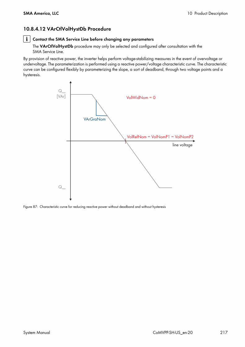
SMA America, LLC 10 Product Description
System Manual CoMVPP-SH-US_en-20 217
10.8.4.12 VArCtlVolHystDb Procedure
By provision of reactive power, the inverter helps perform voltage-stabilizing measures in the event of overvoltage or undervoltage. The parameterization is performed using a reactive power/voltage characteristic curve. The characteristic curve can be configured flexibly by parameterizing the slope, a sort of deadband, through two voltage points and a hysteresis.
Figure 87: Characteristic curve for reducing reactive power without deadband and without hysteresis
Contact the SMA Service Line before changing any parametersThe VArCtlVolHystDb procedure may only be selected and configured after consultation with the SMA Service Line.

10 Product Description SMA America, LLC
218 CoMVPP-SH-US_en-20 System Manual
Figure 88: Characteristic curve for reducing reactive power with deadband
Figure 89: Characteristic curve for reducing reactive power with hysteresis
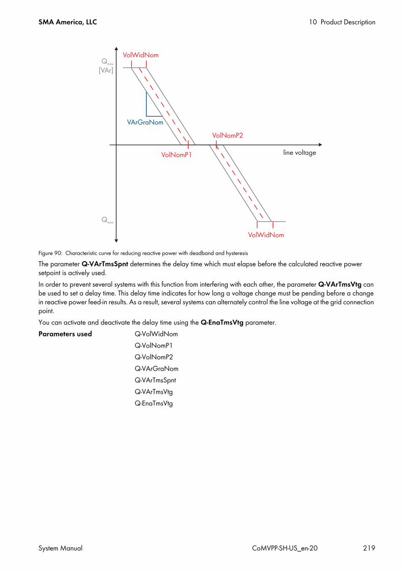
SMA America, LLC 10 Product Description
System Manual CoMVPP-SH-US_en-20 219
Figure 90: Characteristic curve for reducing reactive power with deadband and hysteresisThe parameter Q-VArTmsSpnt determines the delay time which must elapse before the calculated reactive power setpoint is actively used.In order to prevent several systems with this function from interfering with each other, the parameter Q-VArTmsVtg can be used to set a delay time. This delay time indicates for how long a voltage change must be pending before a change in reactive power feed-in results. As a result, several systems can alternately control the line voltage at the grid connection point.You can activate and deactivate the delay time using the Q-EnaTmsVtg parameter.Parameters used Q-VolWidNom
Q-VolNomP1Q-VolNomP2Q-VArGraNomQ-VArTmsSpntQ-VArTmsVtgQ-EnaTmsVtg
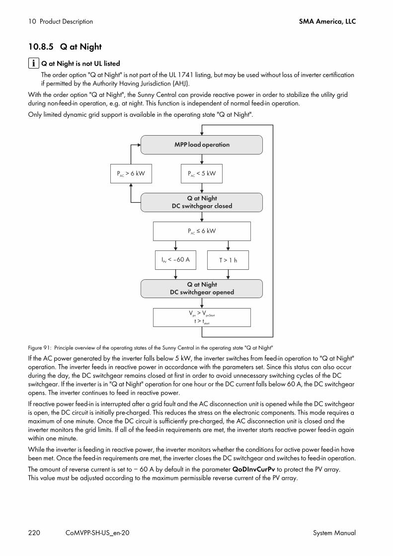
10 Product Description SMA America, LLC
220 CoMVPP-SH-US_en-20 System Manual
10.8.5 Q at Night
With the order option "Q at Night", the Sunny Central can provide reactive power in order to stabilize the utility grid during non-feed-in operation, e.g. at night. This function is independent of normal feed-in operation.Only limited dynamic grid support is available in the operating state "Q at Night".
Figure 91: Principle overview of the operating states of the Sunny Central in the operating state "Q at Night"If the AC power generated by the inverter falls below 5 kW, the inverter switches from feed-in operation to "Q at Night" operation. The inverter feeds in reactive power in accordance with the parameters set. Since this status can also occur during the day, the DC switchgear remains closed at first in order to avoid unnecessary switching cycles of the DC switchgear. If the inverter is in "Q at Night" operation for one hour or the DC current falls below 60 A, the DC switchgear opens. The inverter continues to feed in reactive power.If reactive power feed-in is interrupted after a grid fault and the AC disconnection unit is opened while the DC switchgear is open, the DC circuit is initially pre-charged. This reduces the stress on the electronic components. This mode requires a maximum of one minute. Once the DC circuit is sufficiently pre-charged, the AC disconnection unit is closed and the inverter monitors the grid limits. If all of the feed-in requirements are met, the inverter starts reactive power feed-in again within one minute. While the inverter is feeding in reactive power, the inverter monitors whether the conditions for active power feed-in have been met. Once the feed-in requirements are met, the inverter closes the DC switchgear and switches to feed-in operation.The amount of reverse current is set to − 60 A by default in the parameter QoDInvCurPv to protect the PV array. This value must be adjusted according to the maximum permissible reverse current of the PV array.
Q at Night is not UL listedThe order option "Q at Night" is not part of the UL 1741 listing, but may be used without loss of inverter certification if permitted by the Authority Having Jurisdiction (AHJ).

SMA America, LLC 10 Product Description
System Manual CoMVPP-SH-US_en-20 221
10.8.6 Selecting the Mode with the Parameter QoDQ-VarModThe inverter can supply reactive power in the "Q at Night" operating state if required by the grid operator. The grid operator defines the modes and setpoints used for this. The settings for the "Q at Night" operating state are independent from normal feed-in operation.You can set the mode for reactive power control via the parameter QoDQ-VArMod. Use this parameter to configure how the specifications of the grid operator are to be received and implemented.There are seven different modes for reactive power control. The default value for this parameter is Off.
Procedure:1. Ensure that the inverter is in the operating state "Stop".2. Log in to the user interface.3. Enter the password in the appropriate field on the homepage and confirm with [Login].4. Change the parameter QoDQ-VArMod (see Section 6.6 "Setting the Parameters", page 97).5. Change parameters associated with the selected mode.6. You can select the desired behavior in the absence of setpoint specifications in the parameter PwrMonErrMod as
follows:
Mode DescriptionOff The reactive power setpoint is limited to 0 kVAr.VArCtlCom The communication unit receives the reactive power setpoint via the Power Reducer Box or the
SMA Power Plant Controller, and transmits it to the Sunny Central.VArCnst The parameter QoDQ-VAr is used to set the reactive power setpoint in kVAr.VArCnstNom The parameter QoDQ-VArNom is used to set the reactive power setpoint as a percentage
relative to Pmax.VArCnstNomAnIn The reactive power setpoint is imported via an analog input. The analog value is converted into a
reactive power setpoint. VArCtlVol The reactive power is set depending on the line voltage.VArCtlVolHystDb The provision of reactive power helps perform voltage-stabilizing measures in the event of
overvoltage or undervoltage. The parameterization is carried out by means of a reactive power/voltage characteristic curve.VArCtlVolHysDbA
(for Italy)
Parameter blockThe parameter QoDQ-VarMod can only be changed in the operating state "Stop". The entry will not be accepted in any other operating state.
Validity of parameters in feed-in operation and in Q at Night operationThe parameters used for this proxy value are also valid in feed-in operation and in Q at Night operation.
• Ensure that the settings of the parameters for the proxy values meet the requirements for feed-in and Q at Night operation.
Setting DescriptionLastVal If specified via communication: utilization of the last received value. In case of analog
setpoints: utilization of the last valid mean valueSubVal Utilization of the configured proxy values. SMA recommends use of the proxy values when
setpoint specifications are effected via analog signals.

10 Product Description SMA America, LLC
222 CoMVPP-SH-US_en-20 System Manual
7. If SubVal has been selected, enter the proxy values for normal feed-in operation and for operation outside of normal feed-in operation, as follows:
8. In the parameter PwrMonErrTm configure the time lapse until recognition of the absence of setpoint values.9. Confirm the parameter entry with [Save].
10.8.6.1 No Q at Night: Off ProcedureThe reactive power setpoint is limited to 0 kVAr. This setpoint cannot be controlled.
10.8.6.2 Q at Night with Operation Command via Modbus Protocol: WCtlCom ProcedureThe SC-COM receives the reactive power setpoint via Modbus and transmits it to the inverter. The setpoint is transmitted as a percentage and converted to kVAr in the device.If the inverter has not received any signal for the last five minutes, the error message will be displayed in the instantaneous value Q-VArModFailStt.
10.8.6.3 Q at Night with Absolute Value: VArCnst ProcedureThe reactive power setpoint is set using the parameter QoDQ-VAr. Note that the parameter QoDQ-VAr may be within the range ‒QoDQmax to +QoDQmax.
10.8.6.4 Q at Night as a Percentage of the Nominal Power: VArCnstNom ProcedureThe parameter QoDQ-VArNom is used to set the reactive power setpoint in %. The parameter QoDQ-VArNom refers to Pmax. If the calculated amount of reactive power exceeds the predefined value of QoDQmax, the power will be limited to QoDQmax. If the calculated amount of reactive power falls below the predefined value of ‒QoDQmax, the power will be limited to ‒QoDQmax.
10.8.6.5 Q at Night via Standard Signal: VArCnstNomAnIn ProcedureThe reactive power setpoint is set via an analog signal at the input terminals for setpoint specification (see Sunny Central installation manual). This is usually implemented by a ripple control receiver. The analog value is converted into a reactive power setpoint. The electrical current strength of the connected signal determines the setpoint.The analog measured values must be between 4 mA and 19 mA. If the analog signal is less than 2 mA, the error message will be displayed in the instantaneous value Q-VArModFailStt.
Parameters DescriptionQ-VArSubValRun Proxy value for the reactive power setpoint in feed-in operationPF-PFSubValRun Proxy value for the displacement power factor in feed-in operationPF-PFExtSubValR Proxy value for the excitation of the displacement power factor in feed-in operationQ-VArSubVal Proxy value for the reactive power setpoint outside of feed-in operationPF-PFSubVal Proxy value for the displacement power factor outside of feed-in operationPF-PFExtSubVal Proxy value for the excitation of the displacement power factor outside of feed-in operation
Parameters used none
Parameters used none
Parameters used QoDQ-VAr
Parameters used QoDQ-VArNom

SMA America, LLC 10 Product Description
System Manual CoMVPP-SH-US_en-20 223
The analog value is converted to a setpoint for power limitation. Here, the parameter QoDQmax is the end point of the linear characteristic curve.
Figure 92: Limitation of the parameter Pmax to the parameter QoDQmaxIf the value of Pmax exceeds the value of QoDQmax, the characteristic curve will be limited to QoDQmax at the value QQoDmax and the reactive power value will remain constant at QoDQmax in the range from +QQoDmax to +Pmax.If the value of ‒Pmax falls below the value of ‒QoDQmax, the characteristic curve will be limited to ‒QoDQmax at the value ‒QQoDmax and the reactive power value will remain constant at ‒QoDQmax in the range from ‒Pmax to ‒QQoDmax.
10.8.6.6 Q at Night Depending on the Line Voltage: VArCtlVol Procedure
Signal Power limit Description< 2 mA Last valid value or 0 kVAr
after restartSignal is in the invalid range.
2 mA to 4 mA − Pmax The maximum amount of negatively excited reactive power is fed in.4 mA − Pmax Starting point of the characteristic curve
The maximum amount of negatively excited reactive power is fed in.11.5 mA 0 kVAr Zero-crossing of the characteristic curve
No reactive power is fed in.> 19 mA +Pmax End point of the characteristic curve
The maximum amount of positively excited reactive power is fed in.
Parameters used none
Contact the SMA Service Line before changing any parameters.The SMA Service Line must be consulted prior to selection or configuration of the VArCtlVol mode.

10 Product Description SMA America, LLC
224 CoMVPP-SH-US_en-20 System Manual
The reactive power is configured as a function of the line voltage. The reactive power setpoint is adjusted in stages.
Figure 93: Characteristic curve for reducing reactive power as a function of the line voltageIf the line voltage is changed by the configurable voltage difference Q-VDif for the configurable duration of Q-VDifTm, the reactive power setpoint will be adjusted by the value Q-VArGra.The parameterization of this function refers to the medium voltage.
10.8.6.7 Measures for Voltage Support through Parameterization of Reactive Power/Voltage Characteristic Curve: VArCtlVolHystDb Procedure
The provision of reactive power helps perform voltage-stabilizing measures in the event of overvoltage or undervoltage. The parameterization is carried out by means of a reactive power/voltage characteristic curve. The characteristic curve can be flexibly configured by parameterizing the slope, a type of deadband through two voltage points, and a hysteresis.
Validity of parameters in feed-in operation and in Q at Night operationThe parameters used for this mode are also valid for the VArCtlVol mode in feed-in operation.
• Make sure that the parameter settings meet the requirements of the VArCtlVol mode in feed-in operation and in Q at Night operation.
Parameters used Q-VDif Q-VArGra Q-VDifTm Q-VRtgOfsNom
Contact the SMA Service Line before changing any parameters.The SMA Service Line must be consulted prior to selection or configuration of the VArCtlVolHystDb mode.

SMA America, LLC 10 Product Description
System Manual CoMVPP-SH-US_en-20 225
Figure 94: Characteristic curve for reducing reactive power without deadband and without hysteresis
Figure 95: Characteristic curve for reducing reactive power with deadband

10 Product Description SMA America, LLC
226 CoMVPP-SH-US_en-20 System Manual
Characteristic curve for reducing reactive power with hysteresis
Figure 96: Characteristic curve for reducing reactive power with deadband and hysteresisThe parameter Q-VArTmsSpnt determines the delay time which must elapse before the calculated reactive power setpoint is actively used.
SMA America, LLC 10 Product Description
System Manual CoMVPP-SH-US_en-20 227
To avoid mutual interference of several systems with this function, the parameter Q-VArTmsVtg can be used to set a delay time. This delay time defines how long a voltage change must be pending before a change in reactive power feed-in is triggered. Consequently, control of the line voltage at the grid connection point can be staggered across several systems.You can activate and deactivate the delay time by means of the parameter Q-EnaTmsVtg.
Parameters used Q-VolWidNom Q-VolNomP1 Q-VolNomP2 Q-VArGraNom Q-VArTmsSpnt Q-VArTmsVtg Q-EnaTmsVtg

10 Product Description SMA America, LLC
228 CoMVPP-SH-US_en-20 System Manual
10.8.7 Full and Limited Dynamic Grid Support (FRT)With full dynamic grid support (Fault Ride-Through - FRT), the MV Power Platform supports the utility grid during a brief grid voltage drop by feeding reactive current into the grid. In this case, the behavior of the MV Power Platform depends on the percentage ratio of line voltage VGrid to nominal voltage V. With limited dynamic grid support, the MV Power Platform interrupts grid feed-in during the grid voltage drop.The "FRT" function is set via the parameter FRTEna. The level of reactive current provided with full dynamic grid support is determined via the parameter FRTArGraNom. The "FRT" function cannot be active at the same time as the "Active Islanding Detection" function.
10.8.7.1 Full Dynamic Grid Support (FRT)With full dynamic grid support, the Sunny Central supports the utility grid during a brief grid voltage drop by feeding in reactive current. In this case, the behavior of the Sunny Central depends on the percentage ratio of line voltage VGrid to nominal voltage V.With limited dynamic grid support, the Sunny Central interrupts grid feed-in during the grid voltage drop.
Figure 97: Maximum duration of a voltage dip that the Sunny Central can work through without disconnecting from the utility grid
Ratio VGrid/V Behavior of the Sunny Central90% to 100% The ratio of line voltage VGrid to nominal voltage V is in the normal range and the Sunny Central
feeds in without any problem.20% to 90% The ratio of line voltage VGrid to nominal voltage V is in the critical range. There is a disturbance
in the utility grid. While this disturbance is active, the Sunny Central supports the utility grid with reactive current.The Sunny Central can bridge disturbances of up to two seconds without disconnecting from the utility grid.If the set grid monitoring time is exceeded during this period, the Sunny Central disconnects from the utility grid.

SMA America, LLC 10 Product Description
System Manual CoMVPP-SH-US_en-20 229
0% to 20% The ratio of line voltage VGrid to nominal voltage V is in the critical range. There is a disturbance in the utility grid. While this disturbance is active, the Sunny Central supports the utility grid with reactive current.The Sunny Central can bridge disturbances of up to one second without disconnecting from the utility grid. The requirement is that the ratio VGrid/V was >= 90% before the error occurred.If the set grid monitoring time is exceeded during this period, the Sunny Central disconnects from the utility grid.
Ratio VGrid/V Behavior of the Sunny Central

10 Product Description SMA America, LLC
230 CoMVPP-SH-US_en-20 System Manual
The dynamic grid support function is activated via the parameter FRTEna.The operating mode of the dynamic grid support is set via the parameter FRTMod. Here, you can select full dynamic grid support (FRT_BDEW), full dynamic grid support with FRT characteristic curve (FRT_SDLWindV) and limited dynamic grid support (FRT_Partial).The level of reactive current provided with full dynamic grid support is determined via the parameter FRTArGraNom. The level of reactive current provided with full dynamic grid support with FRT characteristic curve is determined via the parameters FRT2ArGraNomHi and FRT2ArGraNomLo.For the "Q at Night" order option, limited dynamic grid support is available in the operating state "Q at Night".Contact the SMA Service Line to activate the "FRT" function and to change the operating mode.
10.8.7.2 Limited Dynamic Grid Support (LVRT)With limited dynamic grid support, the Sunny Central interrupts grid feed-in during the grid voltage drop.
10.9 Startup Behavior of the Inverter10.9.1 Active Power Ramp-UpIn the operating state "Startup", the MV Power Platform gradually increases feed-in power up to the maximum. Using the parameter WGra, you can set the percentage by which the MV Power Platform is to increase the feed-in power per second. If you do not set this parameter, the MV Power Platform will reach its maximum feed-in power in 400 ms.
10.9.2 Decoupling Protection RampAfter a grid error, the Sunny Central restarts at a maximum of 10% of nominal power per minute using a decoupling protection ramp. You have the option of switching this decoupling protection ramp on or off. If you deactivate the decoupling protection ramp, the Sunny Central will run up to the maximum power in the shortest time possible.If you wish to deactivate the decoupling protection ramp, contact the SMA Service Line.
Full and limited dynamic grid support and islanding detectionThe "FRT" function cannot be active at the same time as the "Active Islanding Detection" function. If the "FRT" function is activated via the parameter FRTEna, the "Active Island Detection" function will be deactivated automatically. Any change to this parameter will therefore forfeit the UL listing.The "FRT" function can be active at the same time as the "Active Islanding Detection" function. To enable this, the parameters VCtllLimTm and VCtlllLimTm must be set to 2,000 ms.

SMA America, LLC 10 Product Description
System Manual CoMVPP-SH-US_en-20 231
10.10 Operating DataThis section describes the instantaneous values of the inverter which you can display on the user interface (see Section 6.4.2, page 90).
10.10.1 Power Limitation
10.10.2 Error Channels
10.10.3 Measured Values
Designation Display ExplanationP-WModFailStt ‒ Error messages and warnings relating to active power limitation
(see Section 7.4.5, page 116)P-WModStt Status messages of active power limitation for data logs
Off No procedure for active power limitation has been selected.WMax Active power is limited by specification of a maximum upper limit. This limit is
based on Pmax.Hz Active power is limited by a frequency increase.Tmp Active power is limited by temperature derating.AmpPv Active power is limited via a PV current limitation.AmpAC Active power is limited via an AC current limitation.
P-WSpt ‒ Current specified power outputPF ‒ Current displacement power factor cos phiPFExt ‒ Current excitation of displacement power factor cos phiQ-VArModFailStt ‒ Errors and warnings relating to the reactive power setpoint
(see Section 7.4.6, page 117)
Designation ExplanationDsc Measure for error correctionErrNo Error numberError Localization of errorGriSwStt State of AC contactorMode Operating state of inverterMsg Error messagePrio Priority of error messageTmsRmg Time until reconnection
Designation ExplanationExtSollIrr External irradiation sensorFac Power frequency in HzIac Line current in AIpv PV current in A

10 Product Description SMA America, LLC
232 CoMVPP-SH-US_en-20 System Manual
10.10.4 Internal Values of Device
10.10.5 Internal Meters
* To view these instantaneous values, you must enter the installer password.
Pac AC power in kWPpv PV power in kWQac Reactive power in kVArRiso Insulation resistanceSac Apparent power in kVAVac Line voltage in VVpv PV voltage in V
Designation ExplanationCntry Country setting or specified standardDInExlStrStp Status of remote shutdownDInGfdi Status of GFDIDInKeySwStrStp Status of key switchDOutMntSvc Status of light signal for PV system maintenanceDt DateFirmware Firmware version of the operation control unitFirmware-2 Firmware version of the digital signal processorTm TimeType Device type
Designation ExplanationCntFanCab1* Operating hours of interior fan 1 in hCntFanCab2* Operating hours of interior fan 2 in hCntFanHs* Operating hours of heat sink fan in hCntFanTrf1* Operating hours of transformer fan 1 in hCntFanTrf2* Operating hours of transformer fan 2 in hCntGfdiSw* Number of GFDI switch cyclesCntHtCab2* Operating hours of heater, in hE-Today Energy fed into the grid during the current day, in kWhE-total Total energy fed into the grid, in kWhh-HighV Operating hours of the Sunny Central at high DC voltageh-On Operating hours of Sunny Central, in hh-Total Feed-in hours of Sunny Central, in h
Designation Explanation

SMA America, LLC 10 Product Description
System Manual CoMVPP-SH-US_en-20 233
10.10.6 Service-Relevant Display ValuesDisplay values that are only relevant to SMA are listed below.Designation ExplanationBfrSolIrr Service information for SMACardSttFirmware-3Firmware-4Firmware-5Firmware-6Firmware-7Firmware-8Firmware-9InfFlgsFirmware-CRCFirmware-2-CRCFirmware-5-CRCFirmware-6-CRCLvrtVtgNomGriSwSttLvrtVtgNomManResSttModeParaSetSttStkErrFirstStkErrFlgsSVMMode
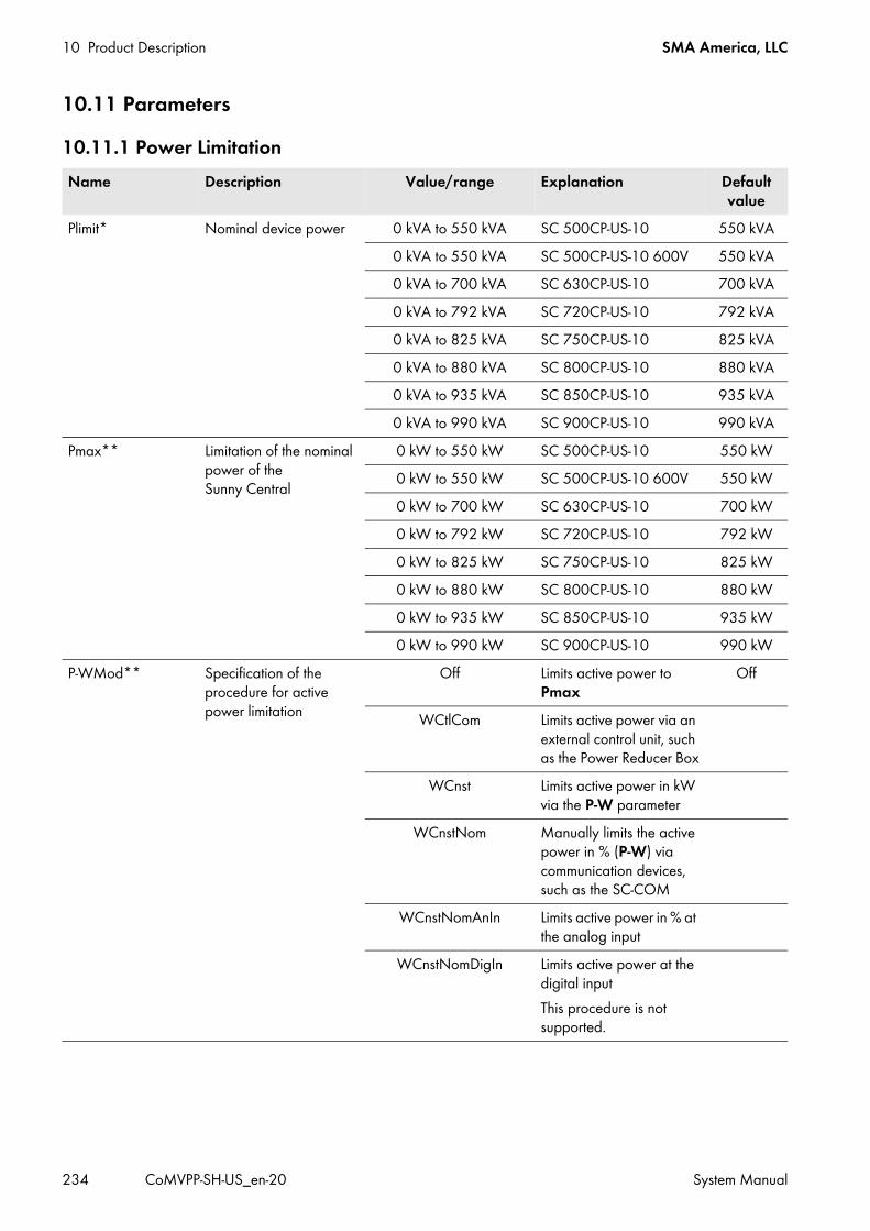
10 Product Description SMA America, LLC
234 CoMVPP-SH-US_en-20 System Manual
10.11 Parameters10.11.1 Power LimitationName Description Value/range Explanation Default
valuePlimit* Nominal device power 0 kVA to 550 kVA SC 500CP-US-10 550 kVA
0 kVA to 550 kVA SC 500CP-US-10 600V 550 kVA0 kVA to 700 kVA SC 630CP-US-10 700 kVA0 kVA to 792 kVA SC 720CP-US-10 792 kVA0 kVA to 825 kVA SC 750CP-US-10 825 kVA0 kVA to 880 kVA SC 800CP-US-10 880 kVA0 kVA to 935 kVA SC 850CP-US-10 935 kVA0 kVA to 990 kVA SC 900CP-US-10 990 kVA
Pmax** Limitation of the nominal power of the Sunny Central
0 kW to 550 kW SC 500CP-US-10 550 kW0 kW to 550 kW SC 500CP-US-10 600V 550 kW0 kW to 700 kW SC 630CP-US-10 700 kW0 kW to 792 kW SC 720CP-US-10 792 kW0 kW to 825 kW SC 750CP-US-10 825 kW0 kW to 880 kW SC 800CP-US-10 880 kW0 kW to 935 kW SC 850CP-US-10 935 kW0 kW to 990 kW SC 900CP-US-10 990 kW
P-WMod** Specification of the procedure for active power limitation
Off Limits active power to Pmax
Off
WCtlCom Limits active power via an external control unit, such as the Power Reducer Box
WCnst Limits active power in kW via the P-W parameter
WCnstNom Manually limits the active power in % (P-W) via communication devices, such as the SC-COM
WCnstNomAnIn Limits active power in % at the analog input
WCnstNomDigIn Limits active power at the digital inputThis procedure is not supported.

SMA America, LLC 10 Product Description
System Manual CoMVPP-SH-US_en-20 235
P-W Limitation of active power in kWThe active power cannot exceed Pmax.
0 kW to 1,000 kW SC 500CP-US-10 550 kWSC 500CP-US-10 600V 550 kWSC 630CP-US-10 700 kWSC 720CP-US-10 792 kWSC 750CP-US-10 825 kWSC 800CP-US-10 880 kWSC 850CP-US-10 935 kWSC 900CP-US-10 990 kW
P-WNom Limitation of active power in %
0% to 100% ‒ 100%
WCtlHzMod** Frequency control setpoint
Off Deactivated OffOn Activated
P-HzStr** Starting point of frequency control
40 Hz to 70 Hz ‒ 60.2 Hz
P-HzStop** End point of frequency control
40 Hz to 70 Hz ‒ 60.05 Hz
P-HzStopMin** Minimum frequency at end point of frequency control
40 Hz to 70 Hz ‒ 60.05 Hz
P-WGra** Gradient of power reduction
1%/Hz to 100%/Hz ‒ 40%/Hz
Qlimit* Reactive power of device 0 kVAr to 332 kVAr SC 500CP-US-10 332 kVAr0 kVAr to 332 kVAr SC 500CP-US-10 600V 332 kVAr0 kVAr to 417 kVAr SC 630CP-US-10 417 kVAr0 kVAr to 477 kVAr SC 720CP-US-10 477 kVAr0 kVAr to 497 kVAr SC 750CP-US-10 497 kVAr0 kVAr to 530 kVAr SC 800CP-US-10 530 kVAr0 kVAr to 561 kVAr SC 850CP-US-10 561 kVAr0 kVAr to 594 kVAr SC 900CP-US-10 594 kVAr
Qmax** Limitation of the reactive power of the inverter
0 kVAr to 550 kVAr SC 500CP-US-10 550 kVAr0 kVAr to 550 kVAr SC 500CP-US-10 600V 550 kVAr0 kVAr to 700 kVAr SC 630CP-US-10 700 kVAr0 kVAr to 792 kVAr SC 720CP-US-10 792 kVAr0 kVAr to 825 kVAr SC 750CP-US-10 825 kVAr0 kVAr to 880 kVAr SC 800CP-US-10 880 kVAr0 kVAr to 935 kVAr SC 850CP-US-10 935 kVAr0 kVAr to 990 kVAr SC 900CP-US-10 990 kVAr
Name Description Value/range Explanation Default value

10 Product Description SMA America, LLC
236 CoMVPP-SH-US_en-20 System Manual
QoDQmax* Limitation of the reactive power of the Sunny Central in the operating state "Q at Night"The reactive power cannot exceed Qlimit.
0 kVAr to 300 kVAr SC 500CP-US-10 300 kVAr0 kVAr to 300 kVAr SC 500CP-US-10 600V 300 kVAr0 kVAr to 378 kVAr SC 630CP-US-10 378 kVAr0 kVAr to 432 kVAr SC 720CP-US-10 432 kVAr0 kVAr to 450 kVAr SC 750CP-US-10 450 kVAr0 kVAr to 480 kVAr SC 800CP-US-10 480 kVAr0 kVAr to 510 kVAr SC 850CP-US-10 510 kVAr0 kVAr to 540 kVAr SC 900CP-US-10 540 kVAr
PFAbsMin* Limitation of the displacement power factor cos φ
0.5 to 1 ‒ 0.8
Name Description Value/range Explanation Default value

SMA America, LLC 10 Product Description
System Manual CoMVPP-SH-US_en-20 237
Q-VArMod** Setpoint for the reactive power setpoint procedure
Off Sets reactive power to 0 kVAr and displacement power factor cos phi to 1
Off
VArCtlCom Specifies reactive power via external control unit, e.g. Power Reducer Box
PFCtlCom Specifies the displacement power factor cos phi and the excitation of the displacement power factor via an external control unit, e.g. Power Reducer Box
VArCnst Specifies reactive power in kVAr via the parameter Q-VAr
VArCnstNom Specifies reactive power in % via the parameter Q-VArNom
VArCnstNomAnIn Specifies reactive power at the analog input QExlSpnt via control unit
PFCnst Manually specifies the displacement power factor cos phi and the excitation of the displacement power factor via the parameters PF-PF and PF-PFExt
PFCnstAnIn Specifies the displacement power factor cos phi at the analog input QExlSpnt via control unit
PFCtlW Specifies the displacement power factor cos phi depending on the feed-in power
VArCtlVol Specifies reactive power depending on the line voltage
VArCtlVolHystDb Specifies reactive power depending on the line voltage (Q = f(V) characteristic curve)
VArCtlVolHysDbA(for Italy)
Name Description Value/range Explanation Default value
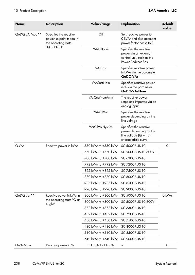
10 Product Description SMA America, LLC
238 CoMVPP-SH-US_en-20 System Manual
QoDQ-VArMod** Specifies the reactive power setpoint mode in the operating state "Q at Night"
Off Sets reactive power to 0 kVAr and displacement power factor cos φ to 1
VArCtlCom Specifies the reactive power via an external control unit, such as the Power Reducer Box
VArCnst Specifies reactive power in kVAr via the parameter QoDQ-VAr
VArCnstNom Specifies reactive power in % via the parameter QoDQ-VArNom
VArCnstNomAnIn The reactive power setpoint is imported via an analog input.
VArCtlVol Specifies the reactive power depending on the line voltage
VArCtlVolHystDb Specifies the reactive power depending on the line voltage (Q = f(V) characteristic curve)
Q-VAr Reactive power in kVAr -550 kVAr to +550 kVAr SC 500CP-US-10 0-550 kVAr to +550 kVAr SC 500CP-US-10 600V-700 kVAr to +700 kVAr SC 630CP-US-10-792 kVAr to +792 kVAr SC 720CP-US-10-825 kVAr to +825 kVAr SC 750CP-US-10-880 kVAr to +880 kVAr SC 800CP-US-10-935 kVAr to +935 kVAr SC 850CP-US-10-990 kVAr to +990 kVAr SC 900CP-US-10
QoDQ-Var** Reactive power in kVAr in the operating state "Q at Night"
-300 kVAr to +300 kVAr SC 500CP-US-10 0 kVAr-300 kVAr to +300 kVAr SC 500CP-US-10 600V-378 kVAr to +378 kVAr SC 630CP-US-10-432 kVAr to +432 kVAr SC 720CP-US-10-450 kVAr to +450 kVAr SC 750CP-US-10-480 kVAr to +480 kVAr SC 800CP-US-10-510 kVAr to +510 kVAr SC 850CP-US-10-540 kVAr to +540 kVAr SC 900CP-US-10
Q-VArNom Reactive power in % − 100% to +100% ‒ 0
Name Description Value/range Explanation Default value
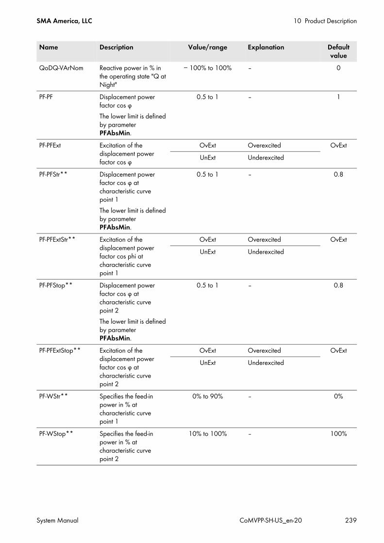
SMA America, LLC 10 Product Description
System Manual CoMVPP-SH-US_en-20 239
QoDQ-VArNom Reactive power in % in the operating state "Q at Night"
− 100% to 100% ‒ 0
PF-PF Displacement power factor cos φThe lower limit is defined by parameter PFAbsMin.
0.5 to 1 ‒ 1
PF-PFExt Excitation of the displacement power factor cos φ
OvExt Overexcited OvExtUnExt Underexcited
PF-PFStr** Displacement power factor cos φ at characteristic curve point 1The lower limit is defined by parameter PFAbsMin.
0.5 to 1 ‒ 0.8
PF-PFExtStr** Excitation of the displacement power factor cos phi at characteristic curve point 1
OvExt Overexcited OvExtUnExt Underexcited
PF-PFStop** Displacement power factor cos φ at characteristic curve point 2The lower limit is defined by parameter PFAbsMin.
0.5 to 1 ‒ 0.8
PF-PFExtStop** Excitation of the displacement power factor cos φ at characteristic curve point 2
OvExt Overexcited OvExtUnExt Underexcited
PF-WStr** Specifies the feed-in power in % at characteristic curve point 1
0% to 90% ‒ 0%
PF-WStop** Specifies the feed-in power in % at characteristic curve point 2
10% to 100% ‒ 100%
Name Description Value/range Explanation Default value

10 Product Description SMA America, LLC
240 CoMVPP-SH-US_en-20 System Manual
PF-WLockInVtg** Power at which the cos φ(P) characteristic curve is activated, in % relative to the nominal voltage
0% to 110% ‒ 0%
PF-WLockOutVtg** Power at which the cos φ(P) characteristic curve is deactivated, in % relative to the nominal voltage
0% to 110% ‒ 0%
PF-WLockTm** Waiting time for activating or deactivating the cos φ(P) characteristic curve
0 s to 100 s ‒ 2 s
Q-VDif** Definition of the voltage change which will trigger a change in reactive power.
0.1% to 10% The value refers to the nominal voltage VRtg.
1%
Q-VArGra** Definition of the reactive power setpoint change during a voltage step.
0% to 100% The value refers to the nominal power Pmax.
1%
Q-VDifTm** Time span for which a voltage change must be pending before the reactive power setpoint Q-VArGra is changed.
0 s to 120 s ‒ 1 s
Q-VRtgOfsNom** Changes the nominal voltage VRtg of the voltage-dependent reactive power controlThis parameter is only active if parameter Q-VArMod is set to VArCtlCol.
− 10% to +10% ‒ 0%
Q-VArGraNom** Reactive power gradient 0%/V to 40.06%/V SC 500CP-US-10 0%/V0%/V to 54.15%/V SC 500CP-US-10 600V0%/V to 31.47%/V SC 630CP-US-100%/V to 27.82%/V SC 720CP-US-100%/V to 26.70%/V SC 750CP-US-100%/V to 25.04%/V SC 800CP-US-100%/V to 23.56%/V SC 850CP-US-100%/V to 22.25%/V SC 900CP-US-10
Q-VolWidNom** Voltage spread 0% to 20% ‒ 0%Q-VolNomP1** Voltage at point 1 80% to 120% ‒ 100%
Name Description Value/range Explanation Default value
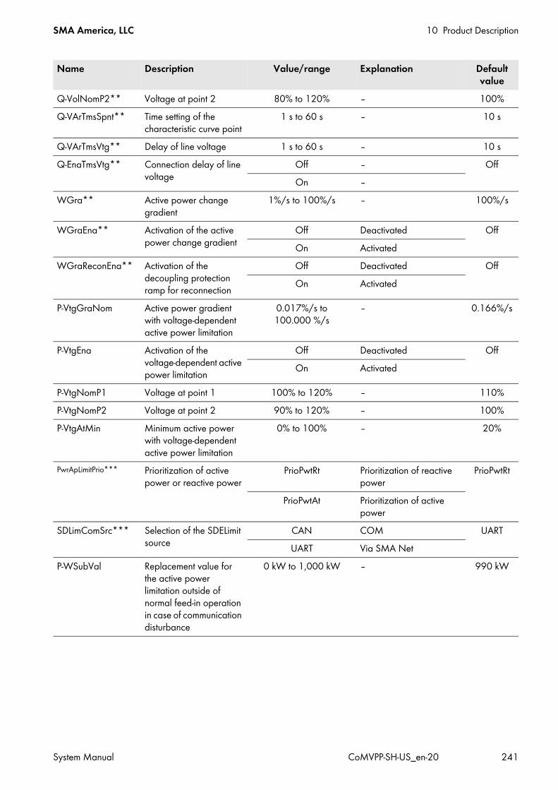
SMA America, LLC 10 Product Description
System Manual CoMVPP-SH-US_en-20 241
Q-VolNomP2** Voltage at point 2 80% to 120% ‒ 100%Q-VArTmsSpnt** Time setting of the
characteristic curve point1 s to 60 s ‒ 10 s
Q-VArTmsVtg** Delay of line voltage 1 s to 60 s ‒ 10 sQ-EnaTmsVtg** Connection delay of line
voltageOff ‒ OffOn ‒
WGra** Active power change gradient
1%/s to 100%/s ‒ 100%/s
WGraEna** Activation of the active power change gradient
Off Deactivated OffOn Activated
WGraReconEna** Activation of the decoupling protection ramp for reconnection
Off Deactivated OffOn Activated
P-VtgGraNom Active power gradient with voltage-dependent active power limitation
0.017%/s to 100.000 %/s
‒ 0.166%/s
P-VtgEna Activation of the voltage-dependent active power limitation
Off Deactivated OffOn Activated
P-VtgNomP1 Voltage at point 1 100% to 120% ‒ 110%P-VtgNomP2 Voltage at point 2 90% to 120% ‒ 100%P-VtgAtMin Minimum active power
with voltage-dependent active power limitation
0% to 100% ‒ 20%
PwrApLimitPrio*** Prioritization of active power or reactive power
PrioPwtRt Prioritization of reactive power
PrioPwtRt
PrioPwtAt Prioritization of active power
SDLimComSrc*** Selection of the SDELimit source
CAN COM UARTUART Via SMA Net
P-WSubVal Replacement value for the active power limitation outside of normal feed-in operation in case of communication disturbance
0 kW to 1,000 kW ‒ 990 kW
Name Description Value/range Explanation Default value
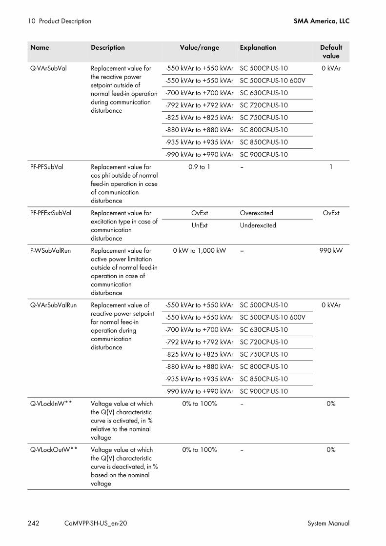
10 Product Description SMA America, LLC
242 CoMVPP-SH-US_en-20 System Manual
Q-VArSubVal Replacement value for the reactive power setpoint outside of normal feed-in operation during communication disturbance
-550 kVAr to +550 kVAr SC 500CP-US-10 0 kVAr-550 kVAr to +550 kVAr SC 500CP-US-10 600V-700 kVAr to +700 kVAr SC 630CP-US-10-792 kVAr to +792 kVAr SC 720CP-US-10-825 kVAr to +825 kVAr SC 750CP-US-10-880 kVAr to +880 kVAr SC 800CP-US-10-935 kVAr to +935 kVAr SC 850CP-US-10-990 kVAr to +990 kVAr SC 900CP-US-10
PF-PFSubVal Replacement value for cos phi outside of normal feed-in operation in case of communication disturbance
0.9 to 1 ‒ 1
PF-PFExtSubVal Replacement value for excitation type in case of communication disturbance
OvExt Overexcited OvExtUnExt Underexcited
P-WSubValRun Replacement value for active power limitation outside of normal feed-in operation in case of communication disturbance
0 kW to 1,000 kW ‒ 990 kW
Q-VArSubValRun Replacement value of reactive power setpoint for normal feed-in operation during communication disturbance
-550 kVAr to +550 kVAr SC 500CP-US-10 0 kVAr-550 kVAr to +550 kVAr SC 500CP-US-10 600V-700 kVAr to +700 kVAr SC 630CP-US-10-792 kVAr to +792 kVAr SC 720CP-US-10-825 kVAr to +825 kVAr SC 750CP-US-10-880 kVAr to +880 kVAr SC 800CP-US-10-935 kVAr to +935 kVAr SC 850CP-US-10-990 kVAr to +990 kVAr SC 900CP-US-10
Q-VLockInW** Voltage value at which the Q(V) characteristic curve is activated, in % relative to the nominal voltage
0% to 100% ‒ 0%
Q-VLockOutW** Voltage value at which the Q(V) characteristic curve is deactivated, in % based on the nominal voltage
0% to 100% ‒ 0%
Name Description Value/range Explanation Default value
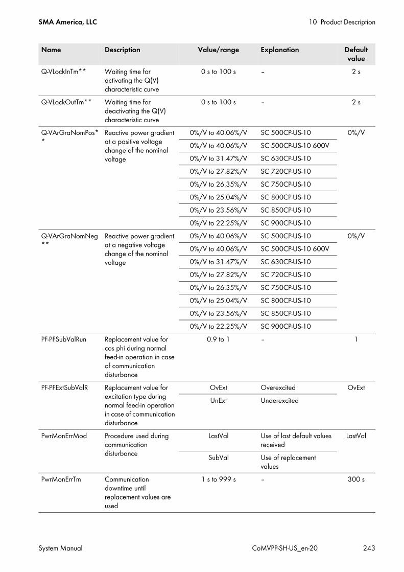
SMA America, LLC 10 Product Description
System Manual CoMVPP-SH-US_en-20 243
Q-VLockInTm** Waiting time for activating the Q(V) characteristic curve
0 s to 100 s ‒ 2 s
Q-VLockOutTm** Waiting time for deactivating the Q(V) characteristic curve
0 s to 100 s ‒ 2 s
Q-VArGraNomPos**
Reactive power gradient at a positive voltage change of the nominal voltage
0%/V to 40.06%/V SC 500CP-US-10 0%/V0%/V to 40.06%/V SC 500CP-US-10 600V0%/V to 31.47%/V SC 630CP-US-100%/V to 27.82%/V SC 720CP-US-100%/V to 26.35%/V SC 750CP-US-100%/V to 25.04%/V SC 800CP-US-100%/V to 23.56%/V SC 850CP-US-100%/V to 22.25%/V SC 900CP-US-10
Q-VArGraNomNeg**
Reactive power gradient at a negative voltage change of the nominal voltage
0%/V to 40.06%/V SC 500CP-US-10 0%/V0%/V to 40.06%/V SC 500CP-US-10 600V0%/V to 31.47%/V SC 630CP-US-100%/V to 27.82%/V SC 720CP-US-100%/V to 26.35%/V SC 750CP-US-100%/V to 25.04%/V SC 800CP-US-100%/V to 23.56%/V SC 850CP-US-100%/V to 22.25%/V SC 900CP-US-10
PF-PFSubValRun Replacement value for cos phi during normal feed-in operation in case of communication disturbance
0.9 to 1 ‒ 1
PF-PFExtSubValR Replacement value for excitation type during normal feed-in operation in case of communication disturbance
OvExt Overexcited OvExtUnExt Underexcited
PwrMonErrMod Procedure used during communication disturbance
LastVal Use of last default values received
LastVal
SubVal Use of replacement values
PwrMonErrTm Communication downtime until replacement values are used
1 s to 999 s ‒ 300 s
Name Description Value/range Explanation Default value
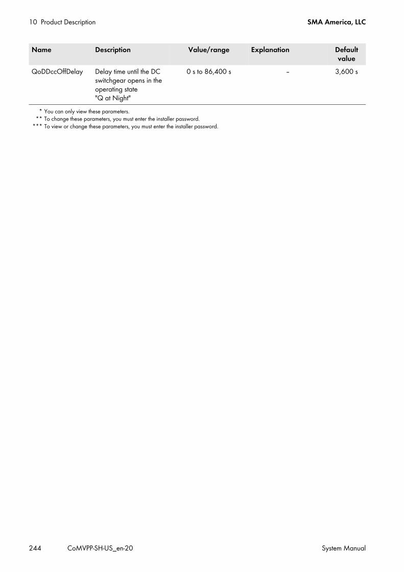
10 Product Description SMA America, LLC
244 CoMVPP-SH-US_en-20 System Manual
QoDDccOffDelay Delay time until the DC switchgear opens in the operating state "Q at Night"
0 s to 86,400 s ‒ 3,600 s
* You can only view these parameters.** To change these parameters, you must enter the installer password.
*** To view or change these parameters, you must enter the installer password.
Name Description Value/range Explanation Default value
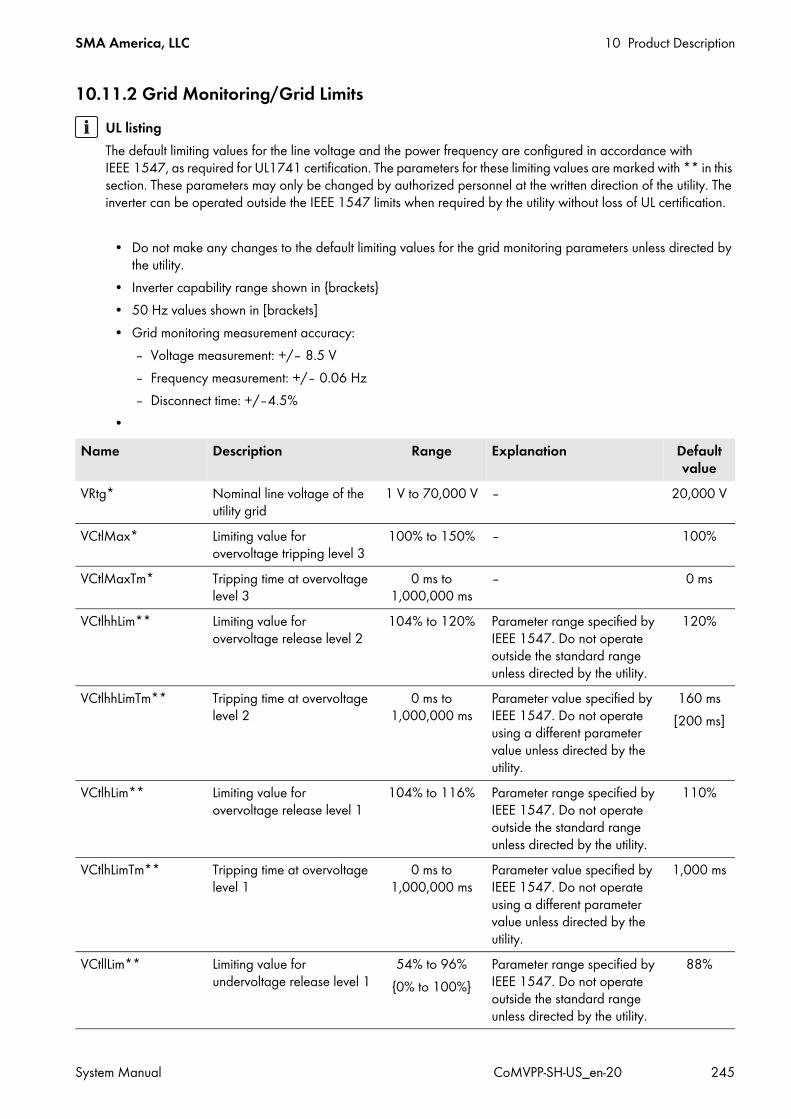
SMA America, LLC 10 Product Description
System Manual CoMVPP-SH-US_en-20 245
10.11.2 Grid Monitoring/Grid LimitsUL listingThe default limiting values for the line voltage and the power frequency are configured in accordance with IEEE 1547, as required for UL1741 certification. The parameters for these limiting values are marked with ** in this section. These parameters may only be changed by authorized personnel at the written direction of the utility. The inverter can be operated outside the IEEE 1547 limits when required by the utility without loss of UL certification.
• Do not make any changes to the default limiting values for the grid monitoring parameters unless directed by the utility.
• Inverter capability range shown in brackets• 50 Hz values shown in [brackets]• Grid monitoring measurement accuracy:
– Voltage measurement: +/– 8.5 V– Frequency measurement: +/– 0.06 Hz– Disconnect time: +/–4.5%
•Name Description Range Explanation Default
valueVRtg* Nominal line voltage of the
utility grid1 V to 70,000 V ‒ 20,000 V
VCtlMax* Limiting value for overvoltage tripping level 3
100% to 150% ‒ 100%
VCtlMaxTm* Tripping time at overvoltage level 3
0 ms to 1,000,000 ms
‒ 0 ms
VCtlhhLim** Limiting value for overvoltage release level 2
104% to 120% Parameter range specified by IEEE 1547. Do not operate outside the standard range unless directed by the utility.
120%
VCtlhhLimTm** Tripping time at overvoltage level 2
0 ms to 1,000,000 ms
Parameter value specified by IEEE 1547. Do not operate using a different parameter value unless directed by the utility.
160 ms[200 ms]
VCtlhLim** Limiting value for overvoltage release level 1
104% to 116% Parameter range specified by IEEE 1547. Do not operate outside the standard range unless directed by the utility.
110%
VCtlhLimTm** Tripping time at overvoltage level 1
0 ms to 1,000,000 ms
Parameter value specified by IEEE 1547. Do not operate using a different parameter value unless directed by the utility.
1,000 ms
VCtllLim** Limiting value for undervoltage release level 1
54% to 96%0% to 100%
Parameter range specified by IEEE 1547. Do not operate outside the standard range unless directed by the utility.
88%

10 Product Description SMA America, LLC
246 CoMVPP-SH-US_en-20 System Manual
VCtllLimTm** Tripping time at undervoltage level 1
160 ms to 2,000 ms
Parameter value specified by IEEE 1547. Do not operate using a different parameter value unless directed by the utility.
2,000 ms
VCtlllLim** Limiting value for undervoltage release level 2
50% to 96%0% to 100%
Parameter range specified by IEEE 1547. Do not operate outside the standard range unless directed by the utility.
50%
VCtlllLimTm** Tripping time at undervoltage level 2
160 ms to 1,000,000 ms
‒ 160 ms[200 ms]
VCtlMin* Limiting value for undervoltage tripping level 3
0% to 100% ‒ 0%
VCtlMinTm* Tripping time at undervoltage level 3
0 ms to 1,000,000 ms
‒ 0 ms
VCtllCharEna* Activation of dynamic undervoltage detection
Off OffOn
VCtllCharTm* Start time dynamic undervoltage detection
0 ms to 1,000,000 ms
‒ 77 ms
VCtlPeakMax* Overvoltage limiting value 120% to 150% ‒ 134%VCtlPeakMaxTm* Tripping time overvoltage 0 ms to 20 ms ‒ 1 msVCtlOpMinNom* Minimum connection voltage 0% to 100% ‒ 95%VCtlOpMaxNom* Maximum connection voltage 100% to 200% ‒ 106%HzCtlOpMin* Minimum connection
frequency55 Hz to 60 Hz
[45 Hz to 50 Hz]‒ 59.5 Hz
[49.5 Hz]HzCtlOpMax* Maximum connection
frequency60 Hz to 65 Hz
[50 Hz to 55 Hz]‒ 60.5 Hz
[50.5 Hz]HzCtlOpMaxRecon* Maximum connection
frequency after grid error60 Hz to 65 Hz
[50 Hz to 55 Hz]‒ 60.5 Hz
[50.5 Hz]HzCtlMax* Limiting value for
overfrequency level 360 Hz to 66 Hz
[50 Hz to 56 Hz]‒ 60 Hz
[50 Hz]HzCtlMaxTm* Tripping time for
overfrequency level 30 ms to
1,000,000 ms‒ 0 ms
HzCtlhhLim* Limiting value for overfrequency level 2
60 Hz to 66 Hz[50 Hz to 56 Hz]
‒ 65 Hz[55 Hz]
HzCtlhhLimTm* Tripping time for overfrequency level 2
0 ms to 1,000,000 ms
‒ 100 ms
Name Description Range Explanation Default value
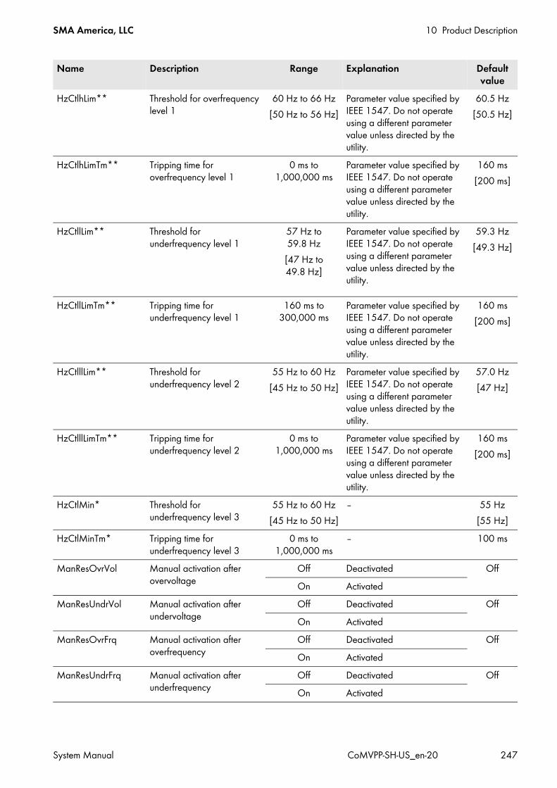
SMA America, LLC 10 Product Description
System Manual CoMVPP-SH-US_en-20 247
HzCtlhLim** Threshold for overfrequency level 1
60 Hz to 66 Hz[50 Hz to 56 Hz]
Parameter value specified by IEEE 1547. Do not operate using a different parameter value unless directed by the utility.
60.5 Hz[50.5 Hz]
HzCtlhLimTm** Tripping time for overfrequency level 1
0 ms to 1,000,000 ms
Parameter value specified by IEEE 1547. Do not operate using a different parameter value unless directed by the utility.
160 ms[200 ms]
HzCtllLim** Threshold for underfrequency level 1
57 Hz to 59.8 Hz[47 Hz to 49.8 Hz]
Parameter value specified by IEEE 1547. Do not operate using a different parameter value unless directed by the utility.
59.3 Hz[49.3 Hz]
HzCtllLimTm** Tripping time for underfrequency level 1
160 ms to 300,000 ms
Parameter value specified by IEEE 1547. Do not operate using a different parameter value unless directed by the utility.
160 ms[200 ms]
HzCtlllLim** Threshold for underfrequency level 2
55 Hz to 60 Hz[45 Hz to 50 Hz]
Parameter value specified by IEEE 1547. Do not operate using a different parameter value unless directed by the utility.
57.0 Hz[47 Hz]
HzCtlllLimTm** Tripping time for underfrequency level 2
0 ms to 1,000,000 ms
Parameter value specified by IEEE 1547. Do not operate using a different parameter value unless directed by the utility.
160 ms[200 ms]
HzCtlMin* Threshold for underfrequency level 3
55 Hz to 60 Hz[45 Hz to 50 Hz]
‒ 55 Hz[55 Hz]
HzCtlMinTm* Tripping time for underfrequency level 3
0 ms to 1,000,000 ms
‒ 100 ms
ManResOvrVol Manual activation after overvoltage
Off Deactivated OffOn Activated
ManResUndrVol Manual activation after undervoltage
Off Deactivated OffOn Activated
ManResOvrFrq Manual activation after overfrequency
Off Deactivated OffOn Activated
ManResUndrFrq Manual activation after underfrequency
Off Deactivated OffOn Activated
Name Description Range Explanation Default value
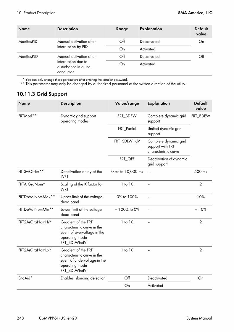
10 Product Description SMA America, LLC
248 CoMVPP-SH-US_en-20 System Manual
10.11.3 Grid Support
ManResPID Manual activation after interruption by PID
Off Deactivated OnOn Activated
ManResPLD Manual activation after interruption due to disturbance in a line conductor
Off Deactivated OffOn Activated
* You can only change these parameters after entering the installer password.** This parameter may only be changed by authorized personnel at the written direction of the utility.
Name Description Value/range Explanation Default value
FRTMod** Dynamic grid support operating modes
FRT_BDEW Complete dynamic grid support
FRT_BDEW
FRT_Partial Limited dynamic grid support
FRT_SDLWindV Complete dynamic grid support with FRT characteristic curve
FRT_OFF Deactivation of dynamic grid support
FRTSwOffTm** Deactivation delay of the LVRT
0 ms to 10,000 ms ‒ 500 ms
FRTArGraNom* Scaling of the K factor for LVRT
1 to 10 ‒ 2
FRTDbVolNomMax** Upper limit of the voltage dead band
0% to 100% ‒ 10%
FRTDbVolNomMin** Lower limit of the voltage dead band
− 100% to 0% ‒ − 10%
FRT2ArGraNomHi* Gradient of the FRT characteristic curve in the event of overvoltage in the operating mode FRT_SDLWindV
1 to 10 ‒ 2
FRT2ArGraNomLo* Gradient of the FRT characteristic curve in the event of undervoltage in the operating mode FRT_SDLWindV
1 to 10 ‒ 2
EnaAid* Enables islanding detection Off Deactivated OnOn Activated
Name Description Range Explanation Default value

SMA America, LLC 10 Product Description
System Manual CoMVPP-SH-US_en-20 249
10.11.4 Insulation Monitoring
TrfVolExlHi* Line-to-line voltage on the overvoltage side of the MV transformer
1 V to 70,000 V ‒ 20,000 V
TrfVolExlLo* Line-to-line voltage on the undervoltage side of the MV transformer
1 V to 500 V SC 500CP-US-10 270 VSC 500CP-US-10 600V 200 VSC 630CP-US-10 315 VSC 720CP-US-10 324 VSC 750CP-US-10 342 VSC 800CP-US-10 360 VSC 850CP-US-10 386 VSC 900CP-US-10 405 V
* You can only change these parameters after entering the installer password.
Name Description Value/range Explanation Default value
IsoErrIgn* Enables insulation error detection
Off Deactivated OnOn Activated
RemMntSvc PV array grounding is deactivated.
Off PV system maintenance off
Off
On PV system maintenance on
IsoSmidOutGrp Procedure for the correction of insulation errors
Auto Automatic insulation measuring
Auto
Man Manual insulation measuring
Start Start of string isolation for insulation measuring
RisoCtlWarn Alert threshold for the insulation monitoring device iso-PV1685
0 kΩ to 50 kΩ ‒ 45 kΩ
PvVtgRisoStart Start voltage of insulation measuring
0 V to 1,200 V SC 500CP-US-10 500 VSC 500CP-US-10 600V 390 VSC 630CP-US-10 610 VSC 720CP-US-10 675 VSC 750CP-US-10 715 VSC 800CP-US-10 760 VSC 850CP-US-10 760 VSC 900CP-US-10 770 V
Name Description Value/range Explanation Default value

10 Product Description SMA America, LLC
250 CoMVPP-SH-US_en-20 System Manual
10.11.5 Internal Values of Device
PvVtgRisoDif Differential voltage to PvVtgStrLevMin for switching from insulation measuring to feed-in operation
− 250 V to +250 V ‒ 0 V
IsoDev* Selection of the insulation monitoring device
isoPV3 ‒ isoPV1685isoPV1685 ‒
* These parameters can only be viewed and changed after entering the installer password.
Name Description Value/range Explanation Default value
PvPwrMinTr Limiting value for starting the MPP tracker
0 W to 20 kW ‒ 20 kW
PvPwrMinTrT Timeout for starting the MPP tracker
1 s to 1,800 s ‒ 600 s
PvVtgStrLevMin* Limiting value for switching to feed-in operation
0 V to 1,800 V SC 500CP-US-10 500 VSC 630CP-US-10 600V 390 VSC 630CP-US-10 610 VSC 720CP-US-10 675 VSC 750CP-US-10 715 VSC 800CP-US-10 760 VSC 850CP-US-10 760 VSC 900CP-US-10 770 V
PVStrT Timer: after time has elapsed, target status switches from Wait-PV to Grid-Connect
1 s to 300 s ‒ 90 s
VArGra** Gradient of reactive power change (VAr/s)
0%/s to 200%/s ‒ 20%/s
QoDInvCurPv** Maximum allowed reverse current to the PV array
− 1,600 A to 0 A ‒ − 60 A
RmpVtgPvSNg Internal channel: negative PV voltage ramp (DSP)
0 V/s to 200 V/s ‒ 200 V/s
RmpVtgPvSPos Internal channel: positive PV voltage ramp (DSP)
0 V/s to 200 V/s ‒ 200 V/s
MppFact Ratio between maximum power PMPP of the PV cell at the maximum power point and the product of open-circuit voltage VOC and short-circuit current ISC
0.5 to 1 ‒ 0.8
Serial Number * Serial number of the Sunny Central
0 to 2,147,483,647 ‒ ‒
Name Description Value/range Explanation Default value

SMA America, LLC 10 Product Description
System Manual CoMVPP-SH-US_en-20 251
CntrySet* Country setting Country-specific ‒ ‒CardFunc* MMC/SD memory card
function‒ ‒ ‒
ForcedWrite SD memory card logoutStoFailHis Writes error history to SD
memory cardDtSet Date 20060101 to
20991231‒ 0
TmSet Time 0 to 235959 ‒ 0TmZn Time zone GMT − 12:00 to
GMT +12:00Time zone setting Country-s
pecificExtSolIrrOfs Offset of the external irradiation
sensor− 5,000 to +5,000 ‒ 0
ExtSolIrrGain Amplification of the external irradiation sensor
− 1,000 to +1,000 ‒ 1
CntRs* Meter reset h-Cnt Operating hours meter ‒E-Cnt Energy meter
CntFanHs All fan runtime metersCntFanCab2 Fan runtime meterCntHtCab2 Fan runtime meter
Ofs_h-On** Offset for operating hours 0 h to 2,147,482 h ‒ 0Ofs_h-Total** Offset for feed-in hours 0 h to 2,147,482 h ‒ 0Ofs_E-Total** Offset for total supplied energy 0 kWh to
214,748,367 kWh‒ 0
Ofs_CntFanHs* Offset for operating hours of heat sink fan
0 h to 2,147,482 h ‒ 0
Ofs_CntFanCab1* Offset for operating hours of internal fan 1
0 h to 2,147,482 h ‒ 0
Ofs_CntFanCab2* Offset for operating hours of internal fan 2
0 h to 2,147,482 h ‒ 0
Ofs_CntHtCab2* Offset for operating hours of internal heater 2
0 h to 2,147,482 h ‒ 0
SpntRemEna Remote activation of the system Stop Deactivated RunRun Activated
Ackn Acknowledgement of errors in Sunny Central
Ackn Parameter selection to acknowledge an error
-
GdErrTm** Waiting time for grid error 0 s to 600 s ‒ 300 sExlStrStpEna* Activation of the external
shutdown signal/remote shutdown
Off Deactivated OffOn Activated
Name Description Value/range Explanation Default value

10 Product Description SMA America, LLC
252 CoMVPP-SH-US_en-20 System Manual
ExlTrfErrEna* Activation of hermetic protection of MV transformer
Off Deactivated OnOn Activated
* These parameters can only be viewed after entering the installer password.** You can only change these parameters after entering the installer password.
Name Description Value/range Explanation Default value
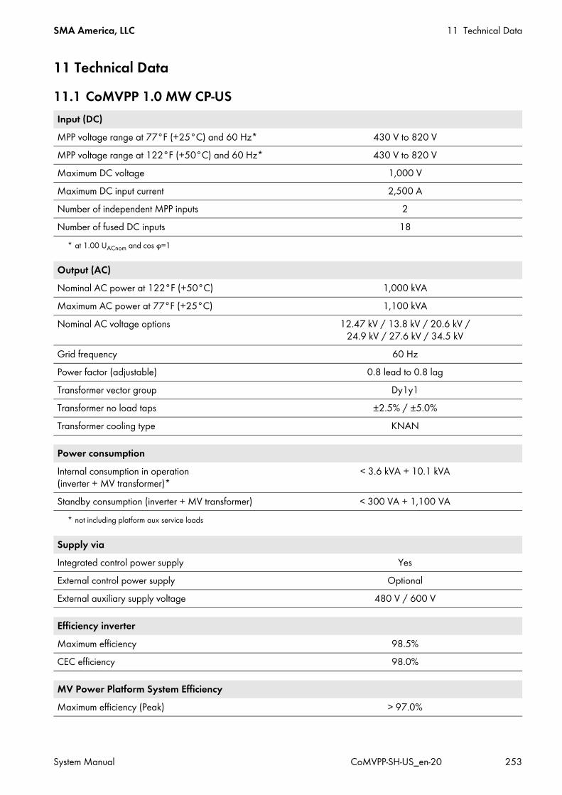
SMA America, LLC 11 Technical Data
System Manual CoMVPP-SH-US_en-20 253
11 Technical Data11.1 CoMVPP 1.0 MW CP-USInput (DC)MPP voltage range at 77°F (+25°C) and 60 Hz*
* at 1.00 UACnom and cos φ=1
430 V to 820 VMPP voltage range at 122°F (+50°C) and 60 Hz* 430 V to 820 VMaximum DC voltage 1,000 VMaximum DC input current 2,500 ANumber of independent MPP inputs 2Number of fused DC inputs 18
Output (AC)Nominal AC power at 122°F (+50°C) 1,000 kVAMaximum AC power at 77°F (+25°C) 1,100 kVANominal AC voltage options 12.47 kV / 13.8 kV / 20.6 kV /
24.9 kV / 27.6 kV / 34.5 kVGrid frequency 60 HzPower factor (adjustable) 0.8 lead to 0.8 lagTransformer vector group Dy1y1Transformer no load taps ±2.5% / ±5.0%Transformer cooling type KNAN
Power consumptionInternal consumption in operation (inverter + MV transformer)*
* not including platform aux service loads
< 3.6 kVA + 10.1 kVA
Standby consumption (inverter + MV transformer) < 300 VA + 1,100 VA
Supply viaIntegrated control power supply YesExternal control power supply OptionalExternal auxiliary supply voltage 480 V / 600 V
Efficiency inverterMaximum efficiency 98.5%CEC efficiency 98.0%
MV Power Platform System EfficiencyMaximum efficiency (Peak) > 97.0%

11 Technical Data SMA America, LLC
254 CoMVPP-SH-US_en-20 System Manual
11.2 CoMVPP 1.25 MW CP-US
Protection rating and ambient conditionsProtection rating IP54 (complies with NEMA 3R)Operation temperature range*
* at nominal power
− 13°F to +122°F ( − 25°C to +50°C)Storage temperature standard − 13°F to +140°F ( − 25°C to +60°C)Relative humidity 15% to 95%Snow load > 40 psf (195 kg/m²)Wind load > 110 mph (177 km/h)Fresh air consumption 3,532 cfm (100 m³/min)Maximum altitude above sea level 6,562 ft. (2,000 m)Design lifetime > 20 yearsSeismic rating for pier height 3 ft. maximum**
** according to UBC sec. 1632 and IBC sec. 1613
Ss=2.25 g, S1=1.24 g
FeaturesCustomer SCADA system compartment (Width x Height x Depth)
34 in. x 30 in. x 12 in. (864 mm x 762 mm x 305 mm)
Supply for customer SCADA system compartment 120 V / 60 Hz / maximum 250 WConvenience receptacles 2 x 120 V / maximum 250 W each
Dimensions and Weight of MV Power Platform with Disconnect UnitLength* x Height x Width
* When configured with the oil containment option, the installed length, including the oil separating valve assembly, is 30 ft. 11 in. (9,423 mm).
30 ft. 6 in. x 8 ft. 6 in. x 8 ft. 6 in. (9,300 mm x 2,590 mm x 2,590 mm)
Weight < 39,000 lbs. (17,690 kg)
Dimensions and Weight of MV Power Platform without Disconnect UnitLength* x Height x Width
* When configured with the oil containment option, the installed length, including the oil separating valve assembly, is 25 ft. 8 in. (7,823 mm).
22 ft. 9.2 in. x 8 ft. 6 in. x 8 ft. 6 in. (6,940 mm x 2,590 mm x 2,590 mm)
Weight < 35,000 lbs. (15,876 kg)
Input (DC)MPP voltage range at 77°F (+25°C) and 60 Hz*
* at 1.00 UACnom and cos φ=1
500 V to 820 VMPP voltage range at 122°F (+50°C) and 60 Hz* 500 V to 820 VMaximum DC voltage 1,000 VMaximum DC input current 2,700 ANumber of independent MPP inputs 2Number of fused DC inputs 18

SMA America, LLC 11 Technical Data
System Manual CoMVPP-SH-US_en-20 255
Output (AC)Nominal AC power at 122°F (+50°C) 1,260 kVAMaximum AC power at 77°F (+25°C) 1,400 kVANominal AC voltage options 12.47 kV / 13.8 kV / 20.6 kV /
24.9 kV / 27.6 kV / 34.5 kVGrid frequency 60 HzPower factor (adjustable) 0.8 lead to 0.8 lagTransformer vector group Dy1y1Transformer no load taps ±2.5% / ±5.0%Transformer cooling type KNAN
Power consumptionInternal consumption in operation (inverter + MV transformer)*
* not including platform aux service loads
< 3.6 kVA + 12.4 kVA
Standby consumption (inverter + MV transformer) < 300 VA + 1,350 VA
Supply viaIntegrated control power supply YesExternal control power supply OptionalExternal auxiliary supply voltage 480 V / 600 V
Efficiency inverterMaximum efficiency 98.5%CEC efficiency 98%
MV Power Platform System EfficiencyMaximum efficiency (Peak) > 97.0%
Protection rating and ambient conditionsProtection rating IP54 (complies with NEMA 3R)Operation temperature range* − 13°F to +122°F ( − 25°C to +50°C)Storage temperature standard − 13°F to +140°F ( − 25°C to +60°C)Relative humidity 15% to 95%Snow load > 40 psf (195 kg/m²)Wind load > 110 mph (177 km/h)Fresh air consumption 3,532 cfm (100 m³/min)Maximum altitude above sea level 6,562 ft. (2,000 m)Design lifetime > 20 years

11 Technical Data SMA America, LLC
256 CoMVPP-SH-US_en-20 System Manual
11.3 CoMVPP 1.44 MW CP-US
Seismic rating for pier height 3 ft. maximum** Ss=2.25 g, S1=1.24 g* at nominal power
** according to UBC sec. 1632 and IBC sec. 1613
FeaturesCustomer SCADA system compartment (Width x Height x Depth)
34 in. x 30 in. x 12 in. (864 mm x 762 mm x 305 mm)
Supply for customer SCADA system compartment 120 V / 60 Hz / maximum 250 WConvenience receptacles 2 x 120 V / maximum 250 W each
Dimensions and Weight of MV Power Platform with Disconnect UnitLength* x Height x Width
* When configured with the oil containment option, the installed length, including the oil separating valve assembly, is 30 ft. 11 in. (9,423 mm).
30 ft. 6 in. x 8 ft. 6 in. x 8 ft. 6 in. (9,300 mm x 2,590 mm x 2,590 mm)
Weight < 39,000 lbs. (17,690 kg)
Dimensions and Weight of MV Power Platform without Disconnect UnitLength* x Height x Width
* When configured with the oil containment option, the installed length, including the oil separating valve assembly, is 25 ft. 8 in. (7,823 mm).
22 ft. 9.2 in. x 8 ft. 6 in. x 8 ft. 6 in. (6,940 mm x 2,590 mm x 2,590 mm)
Weight < 35,000 lbs. (15,876 kg)
Input (DC)MPP voltage range at 77°F (+25°C) and 60 Hz*
* at 1.00 UACnom and cos φ=1
525 V to 820 VMaximum DC voltage 1,000 VMaximum DC input current 3,200 ANumber of independent MPP inputs 2Number of fused DC inputs 18
Output (AC)Nominal AC power at 122°F (+50°C) 1,440 kVAMaximum AC power at 77°F (+25°C) 1,584 kVANominal AC voltage options 12.47 kV / 13.8 kV / 20.6 kV /
24.9 kV / 27.6 kV / 34.5 kVGrid frequency 60 HzPower factor (adjustable) 0.8 lead to 0.8 lagTransformer vector group Dy1y1Transformer no load taps − 5.0% / − 2.5% / +2.5% / +5.0% / +7.5% / +10.0%Transformer cooling type KNAN
Protection rating and ambient conditions
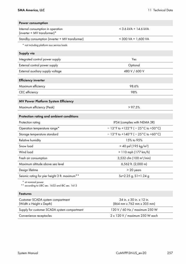
SMA America, LLC 11 Technical Data
System Manual CoMVPP-SH-US_en-20 257
Power consumptionInternal consumption in operation (inverter + MV transformer)*
* not including platform aux service loads
< 3.6 kVA + 14.6 kVA
Standby consumption (inverter + MV transformer) < 300 VA + 1,600 VA
Supply viaIntegrated control power supply YesExternal control power supply OptionalExternal auxiliary supply voltage 480 V / 600 V
Efficiency inverterMaximum efficiency 98.6%CEC efficiency 98%
MV Power Platform System EfficiencyMaximum efficiency (Peak) > 97.5%
Protection rating and ambient conditionsProtection rating IP54 (complies with NEMA 3R)Operation temperature range*
* at nominal power
− 13°F to +122°F ( − 25°C to +50°C)Storage temperature standard − 13°F to +140°F ( − 25°C to +60°C)Relative humidity 15% to 95%Snow load > 40 psf (195 kg/m²)Wind load > 110 mph (177 km/h)Fresh air consumption 3,532 cfm (100 m³/min)Maximum altitude above sea level 6,562 ft. (2,000 m)Design lifetime > 20 yearsSeismic rating for pier height 3 ft. maximum**
** according to UBC sec. 1632 and IBC sec. 1613
Ss=2.25 g, S1=1.24 g
FeaturesCustomer SCADA system compartment (Width x Height x Depth)
34 in. x 30 in. x 12 in. (864 mm x 762 mm x 305 mm)
Supply for customer SCADA system compartment 120 V / 60 Hz / maximum 250 WConvenience receptacles 2 x 120 V / maximum 250 W each

11 Technical Data SMA America, LLC
258 CoMVPP-SH-US_en-20 System Manual
11.4 CoMVPP 1.5 MW CP-US
Dimensions and Weight of MV Power Platform with Disconnect UnitLength* x Height x Width
* When configured with the oil containment option, the installed length, including the oil separating valve assembly, is 30 ft. 11 in. (9,423 mm).
30 ft. 6 in. x 8 ft. 6 in. x 8 ft. 6 in. (9,300 mm x 2,590 mm x 2,590 mm)
Weight < 39,000 lbs. (17,690 kg)
Dimensions and Weight of MV Power Platform without Disconnect UnitLength* x Height x Width
* When configured with the oil containment option, the installed length, including the oil separating valve assembly, is 25 ft. 8 in. (7,823 mm).
22 ft. 9.2 in. x 8 ft. 6 in. x 8 ft. 6 in. (6,940 mm x 2,590 mm x 2,590 mm)
Weight < 35,000 lbs. (15,876 kg)
Input (DC)MPP voltage range at 77°F (+25°C) and 60 Hz*
* at 1.05 UACnom and cos φ=1
545 V to 820 VMPP voltage range at 122°F (+50°C) and 60 Hz* 545 V to 820 VMaximum DC voltage 1,000 VMaximum DC input current 3,200 ANumber of independent MPP inputs 2Number of fused DC inputs 18
Output (AC)Nominal AC power at 122°F (+50°C) 1,500 kVAMaximum AC power at 77°F (+25°C) 1,650 kVANominal AC voltage options 12.47 kV / 13.8 kV / 20.6 kV /
24.9 kV / 27.6 kV / 34.5 kVGrid frequency 60 HzPower factor (adjustable) 0.8 lead to 0.8 lagTransformer vector group Dy1y1Transformer no load taps − 5.0% / − 2.5% / +2.5% / +5.0% / +7.5% / +10.0%Transformer cooling type KNAN
Power consumptionInternal consumption in operation (inverter + MV transformer)*
* not including platform aux service loads
< 3.6 kVA + 14.6 kVA
Standby consumption (inverter + MV transformer) < 300 VA + 1,600 VA
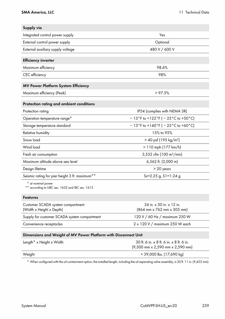
SMA America, LLC 11 Technical Data
System Manual CoMVPP-SH-US_en-20 259
Supply viaIntegrated control power supply YesExternal control power supply OptionalExternal auxiliary supply voltage 480 V / 600 V
Efficiency inverterMaximum efficiency 98.6%CEC efficiency 98%
MV Power Platform System EfficiencyMaximum efficiency (Peak) > 97.5%
Protection rating and ambient conditionsProtection rating IP54 (complies with NEMA 3R)Operation temperature range*
* at nominal power
− 13°F to +122°F ( − 25°C to +50°C)Storage temperature standard − 13°F to +140°F ( − 25°C to +60°C)Relative humidity 15% to 95%Snow load > 40 psf (195 kg/m²)Wind load > 110 mph (177 km/h)Fresh air consumption 3,532 cfm (100 m³/min)Maximum altitude above sea level 6,562 ft. (2,000 m)Design lifetime > 20 yearsSeismic rating for pier height 3 ft. maximum**
** according to UBC sec. 1632 and IBC sec. 1613
Ss=2.25 g, S1=1.24 g
FeaturesCustomer SCADA system compartment (Width x Height x Depth)
34 in. x 30 in. x 12 in. (864 mm x 762 mm x 305 mm)
Supply for customer SCADA system compartment 120 V / 60 Hz / maximum 250 WConvenience receptacles 2 x 120 V / maximum 250 W each
Dimensions and Weight of MV Power Platform with Disconnect UnitLength* x Height x Width
* When configured with the oil containment option, the installed length, including the oil separating valve assembly, is 30 ft. 11 in. (9,423 mm).
30 ft. 6 in. x 8 ft. 6 in. x 8 ft. 6 in. (9,300 mm x 2,590 mm x 2,590 mm)
Weight < 39,000 lbs. (17,690 kg)
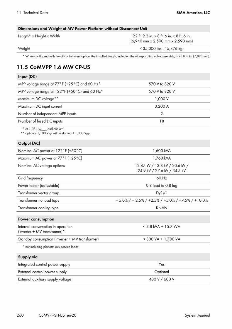
11 Technical Data SMA America, LLC
260 CoMVPP-SH-US_en-20 System Manual
11.5 CoMVPP 1.6 MW CP-US
Dimensions and Weight of MV Power Platform without Disconnect UnitLength* x Height x Width
* When configured with the oil containment option, the installed length, including the oil separating valve assembly, is 25 ft. 8 in. (7,823 mm).
22 ft. 9.2 in. x 8 ft. 6 in. x 8 ft. 6 in. (6,940 mm x 2,590 mm x 2,590 mm)
Weight < 35,000 lbs. (15,876 kg)
Input (DC)MPP voltage range at 77°F (+25°C) and 60 Hz*
* at 1.05 UACnom and cos φ=1
570 V to 820 VMPP voltage range at 122°F (+50°C) and 60 Hz* 570 V to 820 VMaximum DC voltage**
** optional 1,100 VDC with a start-up < 1,000 VDC
1,000 VMaximum DC input current 3,200 ANumber of independent MPP inputs 2Number of fused DC inputs 18
Output (AC)Nominal AC power at 122°F (+50°C) 1,600 kVAMaximum AC power at 77°F (+25°C) 1,760 kVANominal AC voltage options 12.47 kV / 13.8 kV / 20.6 kV /
24.9 kV / 27.6 kV / 34.5 kVGrid frequency 60 HzPower factor (adjustable) 0.8 lead to 0.8 lagTransformer vector group Dy1y1Transformer no load taps − 5.0% / − 2.5% / +2.5% / +5.0% / +7.5% / +10.0%Transformer cooling type KNAN
Power consumptionInternal consumption in operation (inverter + MV transformer)*
* not including platform aux service loads
< 3.8 kVA + 15.7 kVA
Standby consumption (inverter + MV transformer) < 300 VA + 1,700 VA
Supply viaIntegrated control power supply YesExternal control power supply OptionalExternal auxiliary supply voltage 480 V / 600 V

SMA America, LLC 11 Technical Data
System Manual CoMVPP-SH-US_en-20 261
Efficiency inverterMaximum efficiency 98.7%CEC efficiency 98.5%
MV Power Platform System EfficiencyMaximum efficiency (Peak) > 97.5%
Protection rating and ambient conditionsProtection rating IP54 (complies with NEMA 3R)Operation temperature range*
* at nominal power
− 13°F to +122°F ( − 25°C to +50°C)Storage temperature standard − 13°F to +140°F ( − 25°C to +60°C)Relative humidity 15% to 95%Snow load > 40 psf (195 kg/m²)Wind load > 110 mph (177 km/h)Fresh air consumption 3,532 cfm (100 m³/min)Maximum altitude above sea level 6,562 ft. (2,000 m)Design lifetime > 20 yearsSeismic rating for pier height 3 ft. maximum**
** according to UBC sec. 1632 and IBC sec. 1613
Ss=2.25 g, S1=1.24 g
FeaturesCustomer SCADA system compartment (Width x Height x Depth)
34 in. x 30 in. x 12 in. (864 mm x 762 mm x 305 mm)
Supply for customer SCADA system compartment 120 V / 60 Hz / maximum 250 WConvenience receptacles 2 x 120 V / maximum 250 W each
Dimensions and Weight of MV Power Platform with Disconnect UnitLength* x Height x Width
* When configured with the oil containment option, the installed length, including the oil separating valve assembly, is 30 ft. 11 in. (9,423 mm).
30 ft. 6 in. x 8 ft. 6 in. x 8 ft. 6 in. (9,300 mm x 2,590 mm x 2,590 mm)
Weight < 39,000 lbs. (17,690 kg)
Dimensions and Weight of MV Power Platform without Disconnect UnitLength* x Height x Width
* When configured with the oil containment option, the installed length, including the oil separating valve assembly, is 25 ft. 8 in. (7,823 mm).
22 ft. 9.2 in. x 8 ft. 6 in. x 8 ft. 6 in. (6,940 mm x 2,590 mm x 2,590 mm)
Weight < 35,000 lbs. (15,876 kg)
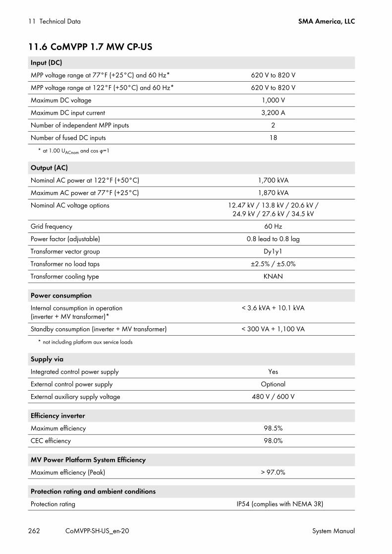
11 Technical Data SMA America, LLC
262 CoMVPP-SH-US_en-20 System Manual
11.6 CoMVPP 1.7 MW CP-US Input (DC)MPP voltage range at 77°F (+25°C) and 60 Hz*
* at 1.00 UACnom and cos φ=1
620 V to 820 VMPP voltage range at 122°F (+50°C) and 60 Hz* 620 V to 820 VMaximum DC voltage 1,000 VMaximum DC input current 3,200 ANumber of independent MPP inputs 2Number of fused DC inputs 18
Output (AC)Nominal AC power at 122°F (+50°C) 1,700 kVAMaximum AC power at 77°F (+25°C) 1,870 kVANominal AC voltage options 12.47 kV / 13.8 kV / 20.6 kV /
24.9 kV / 27.6 kV / 34.5 kVGrid frequency 60 HzPower factor (adjustable) 0.8 lead to 0.8 lagTransformer vector group Dy1y1Transformer no load taps ±2.5% / ±5.0%Transformer cooling type KNAN
Power consumptionInternal consumption in operation (inverter + MV transformer)*
* not including platform aux service loads
< 3.6 kVA + 10.1 kVA
Standby consumption (inverter + MV transformer) < 300 VA + 1,100 VA
Supply viaIntegrated control power supply YesExternal control power supply OptionalExternal auxiliary supply voltage 480 V / 600 V
Efficiency inverterMaximum efficiency 98.5%CEC efficiency 98.0%
MV Power Platform System EfficiencyMaximum efficiency (Peak) > 97.0%
Protection rating and ambient conditionsProtection rating IP54 (complies with NEMA 3R)

SMA America, LLC 11 Technical Data
System Manual CoMVPP-SH-US_en-20 263
11.7 CoMVPP 1.8 MW CP-US
Operation temperature range* − 13°F to +122°F ( − 25°C to +50°C)Storage temperature standard − 13°F to +140°F ( − 25°C to +60°C)Relative humidity 15% to 95%Snow load > 40 psf (195 kg/m²)Wind load > 110 mph (177 km/h)Fresh air consumption 3,532 cfm (100 m³/min)Maximum altitude above sea level 6,562 ft. (2,000 m)Design lifetime > 20 yearsSeismic rating for pier height 3 ft. maximum** Ss=2.25 g, S1=1.24 g
* at nominal power** according to UBC sec. 1632 and IBC sec. 1613
FeaturesCustomer SCADA system compartment (Width x Height x Depth)
34 in. x 30 in. x 12 in. (864 mm x 762 mm x 305 mm)
Supply for customer SCADA system compartment 120 V / 60 Hz / maximum 250 WConvenience receptacles 2 x 120 V / maximum 250 W each
Dimensions and Weight of MV Power Platform with Disconnect UnitLength* x Height x Width
* When configured with the oil containment option, the installed length, including the oil separating valve assembly, is 30 ft. 11 in. (9,423 mm).
30 ft. 6 in. x 8 ft. 6 in. x 8 ft. 6 in. (9,300 mm x 2,590 mm x 2,590 mm)
Weight < 39,000 lbs. (17,690 kg)
Dimensions and Weight of MV Power Platform without Disconnect UnitLength* x Height x Width
* When configured with the oil containment option, the installed length, including the oil separating valve assembly, is 25 ft. 8 in. (7,823 mm).
22 ft. 9.2 in. x 8 ft. 6 in. x 8 ft. 6 in. (6,940 mm x 2,590 mm x 2,590 mm)
Weight < 35,000 lbs. (15,876 kg)
Input (DC)MPP voltage range at 77°F (+25°C) and 60 Hz* 655 V to 820 VMPP voltage range at 122°F (+50°C) and 60 Hz* 655 V to 820 VMaximum DC voltage 1,000 VMaximum DC input current 3,200 ANumber of independent MPP inputs 2Number of fused DC inputs 18
Protection rating and ambient conditions

11 Technical Data SMA America, LLC
264 CoMVPP-SH-US_en-20 System Manual
* at 1.00 UACnom and cos φ=1
Output (AC)Nominal AC power at 122°F (+50°C) 1,800 kVAMaximum AC power at 77°F (+25°C) 1,980 kVANominal AC voltage options 12.47 kV / 13.8 kV / 20.6 kV /
24.9 kV / 27.6 kV / 34.5 kVGrid frequency 60 HzPower factor (adjustable) 0.8 lead to 0.8 lagTransformer vector group Dy1y1Transformer no load taps ±2.5% / ±5.0%Transformer cooling type KNAN
Power consumptionInternal consumption in operation (inverter + MV transformer)*
* not including platform aux service loads
< 3.6 kVA + 10.1 kVA
Standby consumption (inverter + MV transformer) < 300 VA + 1,100 VA
Supply viaIntegrated control power supply YesExternal control power supply OptionalExternal auxiliary supply voltage 480 V / 600 V
Efficiency inverterMaximum efficiency 98.5%CEC efficiency 98.0%
MV Power Platform System EfficiencyMaximum efficiency (Peak) > 97.0%
Protection rating and ambient conditionsProtection rating IP54 (complies with NEMA 3R)Operation temperature range* − 13°F to +122°F ( − 25°C to +50°C)Storage temperature standard − 13°F to +140°F ( − 25°C to +60°C)Relative humidity 15% to 95%Snow load > 40 psf (195 kg/m²)Wind load > 110 mph (177 km/h)Fresh air consumption 3,532 cfm (100 m³/min)Maximum altitude above sea level 6,562 ft. (2,000 m)Design lifetime > 20 years

SMA America, LLC 11 Technical Data
System Manual CoMVPP-SH-US_en-20 265
Seismic rating for pier height 3 ft. maximum** Ss=2.25 g, S1=1.24 g* at nominal power
** according to UBC sec. 1632 and IBC sec. 1613
FeaturesCustomer SCADA system compartment (Width x Height x Depth)
34 in. x 30 in. x 12 in. (864 mm x 762 mm x 305 mm)
Supply for customer SCADA system compartment 120 V / 60 Hz / maximum 250 WConvenience receptacles 2 x 120 V / maximum 250 W each
Dimensions and Weight of MV Power Platform with Disconnect UnitLength* x Height x Width
* When configured with the oil containment option, the installed length, including the oil separating valve assembly, is 30 ft. 11 in. (9,423 mm).
30 ft. 6 in. x 8 ft. 6 in. x 8 ft. 6 in. (9,300 mm x 2,590 mm x 2,590 mm)
Weight < 39,000 lbs. (17,690 kg)
Dimensions and Weight of MV Power Platform without Disconnect UnitLength* x Height x Width
* When configured with the oil containment option, the installed length, including the oil separating valve assembly, is 25 ft. 8 in. (7,823 mm).
22 ft. 9.2 in. x 8 ft. 6 in. x 8 ft. 6 in. (6,940 mm x 2,590 mm x 2,590 mm)
Weight < 35,000 lbs. (15,876 kg)
Protection rating and ambient conditions

12 Appendix SMA America, LLC
266 CoMVPP-SH-US_en-20 System Manual
12 Appendix12.1 Mounting Information12.1.1 Requirements for the Mounting Location The mounting location must be accessible at all times. The altitude of the mounting location must be below the maximum installation altitude (see Section 11, page 253). The ambient temperature must be within the operating temperature range (see Section 11, page 253). The front of the Auxiliary Services Rack of the MV Power Platform is either facing East, South or West. This prevents
the back of the Auxiliary Services Rack from getting too hot. High temperatures can damage the components inside or impair their functionality.
12.1.2 Requirements for the Support SurfaceThe MV Power Platform requires a suitable support surface for mounting. If the support surface is made of concrete, the MV Power Platform should be anchored to the support surface with anchor clips. The excavation pit and foundation must be prepared by the customer according to the project-specific weight and structural plan. The project-specific weight and structural calculation for the MV Power Platform has already been sent to you by SMA upon receipt of your order.In order to facilitate access to the MV Power Platform, SMA recommends inserting the base frame of the MV Power Platform into the ground in such a way that the base frame is flush with the ground level.
Ensuring sufficient space for the oil separator• In case of order option with oil tray, you must ensure that there is sufficient space for the oil separator and the
necessary maintenance work before inserting the MV Power Platform into the ground.• Cover the shaft for the oil separator.
Providing a catwalk for MV Power Platforms installed in an elevated position• If the base frame of the MV Power Platform is positioned more than 2 in. (50 mm) above ground level for one
of the selected installation types, a catwalk around the platform as well as railings and stairs for the catwalk must be provided for maintenance work and operation of the MV Power Platform. The catwalk, railings and stairs must meet the applicable requirements of the OSHA, NEC and AHJ directives.
• The catwalk is to be provided and installed by the customer. The catwalk must be mounted prior to SMA commissioning activities.

SMA America, LLC 12 Appendix
System Manual CoMVPP-SH-US_en-20 267
Figure 98: Overview of mounting surface
There are four possibilities for the support surface:• Concrete piers
If the MV Power Platform is to be mounted on supporting pillars, these must be located as close as possible to the suspension points for the lifting lugs (see Section 12.1.4, page 269). At least six supporting pillars are required.
• Concrete barsIf the MV Power Platform is to be mounted on beams, these must be located underneath the suspension points for the lifting lugs (see Section 12.1.4, page 269).
• Concrete padThe MV Power Platform can be mounted on a lean concrete plate. In this case, the cables do not have to be laid in conduits.
• GravelThe MV Power Platform can be mounted on a solid ballast bed.
If the base frame of the MV Power Platform is positioned more than 2 in. (50 mm) above ground level for one of the selected installation types, a catwalk around the platform as well as railings and stairs for the catwalk must be provided for maintenance work and operation of the MV Power Platform. Ensure that the following requirements are met: The exterior grounding systems according to the instructions of the grid operator or distribution grid operator are in
place. A working area of at least 20 in. (500 mm) around the foundation must be available. The corners of the excavation pit are clearly marked. The excavated material is dumped in a location which will not hinder the trucks during transport. The subgrade is drawn off level. The unevenness of the support surface must not be more than 0.25%.
Position DesignationA Space for maintenance work on oil separatorB Cover of the shaft over the oil separatorC Base frameD Mounting surface
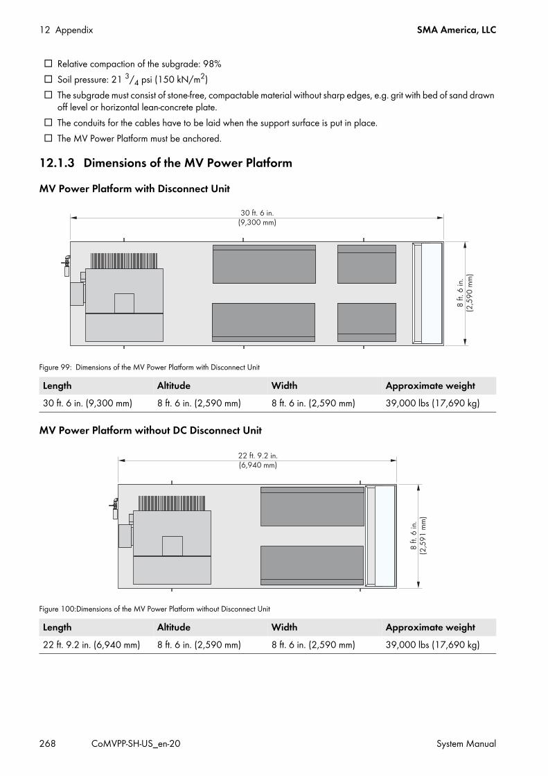
12 Appendix SMA America, LLC
268 CoMVPP-SH-US_en-20 System Manual
Relative compaction of the subgrade: 98% Soil pressure: 21 3/4 psi (150 kN/m2) The subgrade must consist of stone-free, compactable material without sharp edges, e.g. grit with bed of sand drawn
off level or horizontal lean-concrete plate. The conduits for the cables have to be laid when the support surface is put in place. The MV Power Platform must be anchored.
12.1.3 Dimensions of the MV Power PlatformMV Power Platform with Disconnect Unit
Figure 99: Dimensions of the MV Power Platform with Disconnect Unit
MV Power Platform without DC Disconnect Unit
Figure 100:Dimensions of the MV Power Platform without Disconnect Unit
Length Altitude Width Approximate weight30 ft. 6 in. (9,300 mm) 8 ft. 6 in. (2,590 mm) 8 ft. 6 in. (2,590 mm) 39,000 lbs (17,690 kg)
Length Altitude Width Approximate weight22 ft. 9.2 in. (6,940 mm) 8 ft. 6 in. (2,590 mm) 8 ft. 6 in. (2,590 mm) 39,000 lbs (17,690 kg)

SMA America, LLC 12 Appendix
System Manual CoMVPP-SH-US_en-20 269
12.1.4 Position of the Supporting PillarsIf the MV Power Platform is to be mounted on supporting pillars, these must be located as close as possible to the suspension points for the lifting lugs.
MV Power Platform with Disconnect Unit
Figure 101:Position of supporting pillars for the MV Power Platform with Disconnect Unit (example)
MV Power Platform without DC Disconnect Unit
Figure 102:Position of supporting pillars for the MV Power Platform without Disconnect Unit (example)
12.1.5 Minimum ClearancesFor optimum operation of the MV Power Platform, observe the following points: Do not block or close any exhaust air outlets on the devices. The exhaust air outlets on the devices must be accessible for cleaning at all times.
Recommended clearances for the facilitation of installation and service workTo facilitate mounting and cleaning, SMA Solar Technology AG and the National Electrical Code® 2011 require clearances of 4 ft. (1,300 mm) around the MV Power Platform. The properties of the accessible support surface must meet the requirements of the mounting surface (see Section 12.1.2, page 266) or a suitable catwalk with railing must be installed.
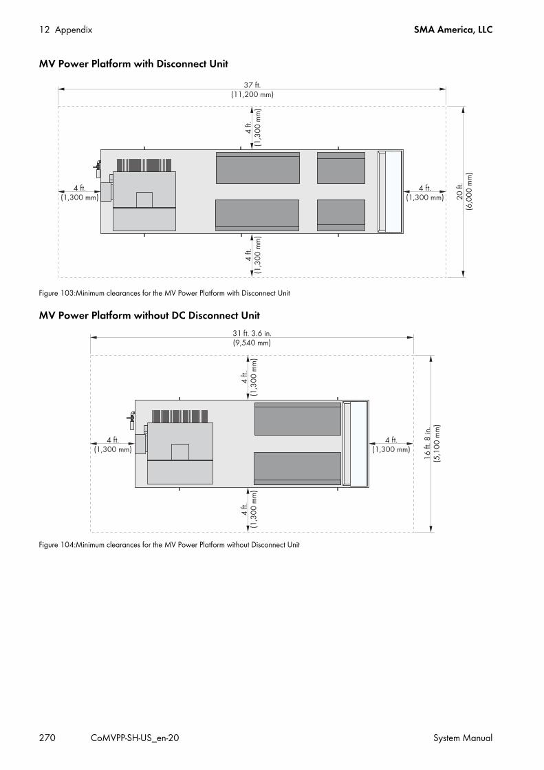
12 Appendix SMA America, LLC
270 CoMVPP-SH-US_en-20 System Manual
MV Power Platform with Disconnect Unit
Figure 103:Minimum clearances for the MV Power Platform with Disconnect Unit
MV Power Platform without DC Disconnect Unit
Figure 104:Minimum clearances for the MV Power Platform without Disconnect Unit

SMA America, LLC 12 Appendix
System Manual CoMVPP-SH-US_en-20 271
12.2 StorageThe information in this section is relevant if the MV Power Platform cannot be mounted immediately on a suitable foundation or base. Note these instructions to prevent damage to the MV Power Platform.
12.3 Installation Information12.3.1 Requirements for Cables and Terminal Lugs for PE, DC and AC ConnectionsCables: All cables must be suitable for temperatures of up +197°F (+90°C) and in accordance with the
National Electrical Code® ANSI/NFPA 70. Conductor cross-sections must be selected in compliance with the National Electrical Code® 310 and must have
sufficient ampacity. Use copper or aluminum cables only.
Terminal lugs: All used terminal lugs must have a valid UL approval. All terminal lugs used must be UL certified crimp-type terminal lugs with two securement holes
(diameter: 0.5 in. (3 mm)). A minimum clearance of 1.75 in. (44 mm) must be maintained between the holes. Both holes have to be utilized in installation.
The terminal lug width must be larger than the diameter of the washers (1.25 in. (32 mm)). This will ensure that the specified torques are effective over the whole surface.
Only use tin-plated terminal lugs. Only use screws, nuts and washers included in the scope of delivery. All torques must always be complied with.
Damage to the MV Power Platform due to improper storageIf the MV Power Platform is not stored properly, the frame construction and the devices of the MV Power Platform may be damaged. Dust and moisture can penetrate the devices of the MV Power Platform and damage electronic components.
• The support surface must be suitable for the weight of the MV Power Platform.• The unevenness of the support surface must not be more than 0.25%.• Store at a temperature between ‒13°F to 140°F (‒25°C to +50°C).• Store the MV Power Platform only when all devices are closed.
Storage in high humidityIf you connect the external voltage supply and switch on the circuit breaker of the external voltage supply during storage of the MV Power Platform, the heating element will be activated automatically in the event of high humidity (see Section "Electrical Connection" in the respective inverter manual).
12 Appendix SMA America, LLC
272 CoMVPP-SH-US_en-20 System Manual
12.4 Torques12.4.1 Torques of PE, DC and AC ConnectionsThe torques to be adhered to depend on the materials of the terminal lugs used as well as on the cable cross-section
12.4.2 Torques for Panels, Grounding Cables and Protective Covers in the Inverter
12.5 Type Labels12.5.1 MV Power PlatformThe type label clearly identifies the MV Power Platform. Two type labels are attached to the MV Power Platform. The type labels are positioned on the base frame between the MV transformer and inverter 1 and on the left-hand inside of the Auxiliary Services Rack.You will require the information on the type label to use the product safely and when seeking customer support from the SMA Service Line. The type label must remain permanently attached to the product.
12.5.2 InverterThe type label clearly identifies the product. Two type labels are attached to the inverter. The type labels can be found at the top right on the inside of the interface cabinet and on the top left-hand side of the inverter cabinet.You will require the information on the type label to use the product safely and when seeking customer support from the SMA Service Line. The type labels must be permanently attached to the product.
You will require the information on the type label to use the product safely and when seeking customer support from the SMA Service Line. The type label must remain permanently attached to the product.
Connection option Cable cross-section TorqueCable connection with aluminum terminal lugs
4 AWG to 800 kcmil (25 mm2 to 405 mm2)
27.5 ft-lb. (37 Nm)
Cable connection with copper terminal lugs
4 AWG to 800 kcmil (25 mm2 to 405 mm2)
44.5 ft-lb. (60 Nm)
Devices TorqueGrounding cable on roof of inverter 125.7 in-lb. (14.2 Nm)Grounding cable on the panels of the inverter 70.8 in-lb. to 88.5 in-lb. (8 Nm to 10 Nm)Panels on the inverter 17.7 in-lb. to 26.5 in-lb. (2 Nm to 3 Nm)Ventilation grid on the roof of the inverter 177.0 in-lb. (20 Nm)Protective covers in the inverter (without cover in front of the AC main switch)
88.5 in-lb. (10 Nm)
Protective cover in front of the AC main switch 26.5 in-lb. (3 Nm)
Reading off the serial numberYou can read off the serial number without opening the inverter. The serial number can be found on the roof of the inverter at the top left. You can also read off the serial number from the display.
Reading off the firmware versionYou can read the version number of the firmware of the inverter and the touch display via the user interface or on the touch display.

SMA America, LLC 12 Appendix
System Manual CoMVPP-SH-US_en-20 273
12.5.3 SC-COMThe type label clearly identifies the SC-COM. The type label can be found on the top of the enclosure.The type label contains a label with the serial number of the SC-COM, the registration ID and the MAC addresses of the LAN interfaces. You can pull off this label and attach it to your documents or to a place where you can quickly access the data.The firmware version can be found in the user interface. The current firmware version is displayed on the right-hand side of the status bar.You will require the information on the type label to use the product safely and when seeking customer support from the SMA Service Line. The type label must remain permanently attached to the product.
12.5.4 Auxiliary Services RackThe type label clearly identifies the Auxiliary Services Rack. The type label is located on the left-hand inside of the Auxiliary Services Rack.You will require the information on the type label to use the product safely and when seeking customer support from the SMA Service Line. The type label must remain permanently attached to the product.
12.5.5 Main BoxThe type label clearly identifies the Main Box. Two type labels are attached to the Main Box. The type labels are attached on the top of the door and on the bottom left-hand side of the Main Box.You will require the information on the type label to use the product safely and when seeking customer support from the SMA Service Line. The type label must remain permanently attached to the product.
12.5.6 Inverter BoxThe type label clearly identifies the Inverter Box. Two type labels are attached to the Inverter Box. The type labels are attached on the top of the door and on the bottom left-hand side of the Inverter Box.You will require the information on the type label to use the product safely and when seeking customer support from the SMA Service Line. The type label must remain permanently attached to the product.
12.5.7 Tracker BoxThe type label clearly identifies the Tracker Box. Two type labels are attached to the Tracker Box. The type labels can be found on the top of the door and on the bottom left-hand side in the Tracker Box.You will require the information on the type label to use the product safely and when seeking customer support from the SMA Service Line. The type label must remain permanently attached to the product.
12.5.8 Brown Power BoxThe type label clearly identifies the Brown Power Box. Two type labels are attached to the Brown Power Box. The type labels can be found on the top of the door and on the bottom left-hand side in the Brown Power Box.You will require the information on the type label to use the product safely and when seeking customer support from the SMA Service Line. The type label must remain permanently attached to the product.
12.5.9 MV TransformerThe type label clearly identifies the MV transformer. The type label is attached to the side panel of the MV transformer on the right-hand side of the medium-voltage load-break switch. The position of the type label may vary depending on the manufacturer (see MV transformer documentation).You will require the information on the type label to use the product safely and when seeking customer support from the SMA Service Line. The type label must remain permanently attached to the product.
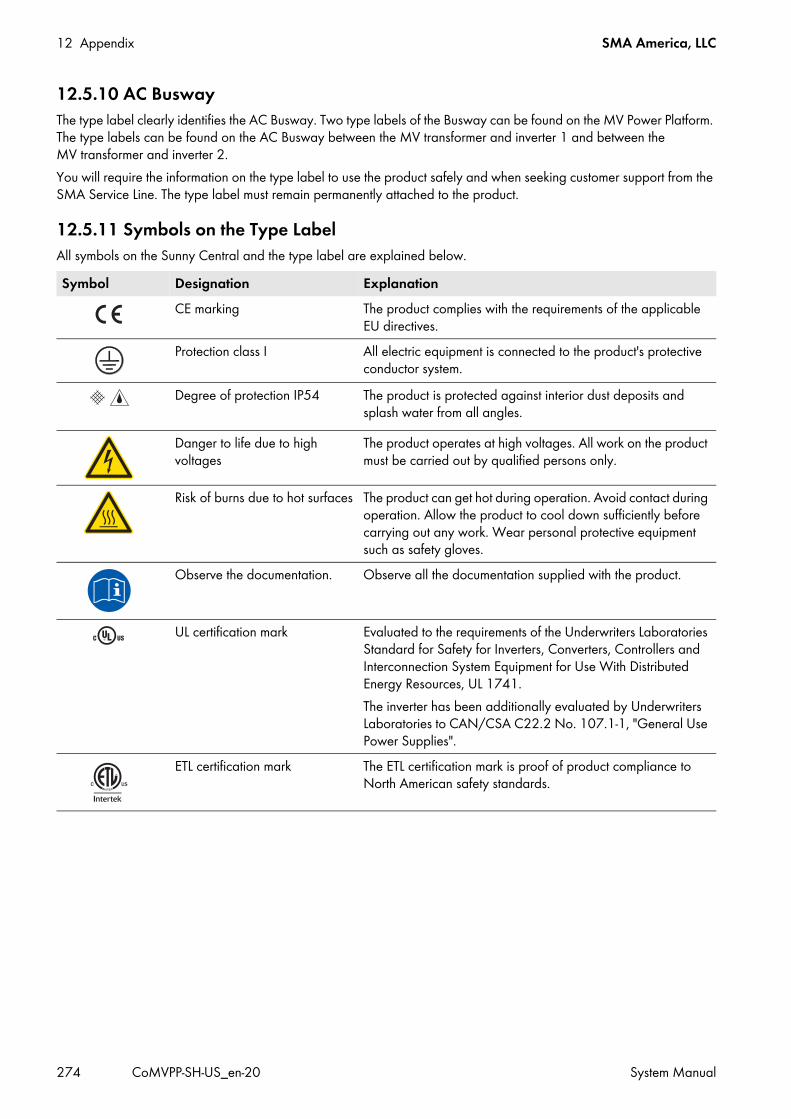
12 Appendix SMA America, LLC
274 CoMVPP-SH-US_en-20 System Manual
12.5.10 AC BuswayThe type label clearly identifies the AC Busway. Two type labels of the Busway can be found on the MV Power Platform. The type labels can be found on the AC Busway between the MV transformer and inverter 1 and between the MV transformer and inverter 2.You will require the information on the type label to use the product safely and when seeking customer support from the SMA Service Line. The type label must remain permanently attached to the product.
12.5.11 Symbols on the Type LabelAll symbols on the Sunny Central and the type label are explained below.Symbol Designation Explanation
CE marking The product complies with the requirements of the applicable EU directives.
Protection class I All electric equipment is connected to the product's protective conductor system.
Degree of protection IP54 The product is protected against interior dust deposits and splash water from all angles.
Danger to life due to high voltages
The product operates at high voltages. All work on the product must be carried out by qualified persons only.
Risk of burns due to hot surfaces The product can get hot during operation. Avoid contact during operation. Allow the product to cool down sufficiently before carrying out any work. Wear personal protective equipment such as safety gloves.
Observe the documentation. Observe all the documentation supplied with the product.
UL certification mark Evaluated to the requirements of the Underwriters Laboratories Standard for Safety for Inverters, Converters, Controllers and Interconnection System Equipment for Use With Distributed Energy Resources, UL 1741.The inverter has been additionally evaluated by Underwriters Laboratories to CAN/CSA C22.2 No. 107.1-1, "General Use Power Supplies".
ETL certification mark The ETL certification mark is proof of product compliance to North American safety standards.

SMA America, LLC 13 Contact
System Manual CoMVPP-SH-US_en-20 275
13 ContactIf you have technical problems concerning our products, contact the SMA Service Line. We require the following information in order to provide you with the necessary assistance:
• Device type• Serial number of the MV Power Platform• Serial number of the component• Type and number of the PV modules connected• Type of communication• Error number and error message
Country Company Name SMA Service LineAmerica SMA America, LLC
Rocklin, CA+1 877-MY-SMATech (+1 877-697-6283)*+1 916 625-0870**
* toll free for USA, Canada and Puerto Rico** international
Canada SMA Canada, Inc.Toronto
+1 877-MY-SMATech (+1 877-697-6283)***
*** toll free for Canada

14 Revision History SMA America, LLC
276 CoMVPP-SH-US_en-20 System Manual
14 Revision HistoryIn this section, you will find an overview of the content changes in the new version of this document. The pages where changes were made are indicated behind the version.
Revisions to version 1.1New 24 month maintenance
Check bolted power connections 122New content
Safety during installation 29New Danger
Entering the PV field 16New danger
Q at Night 17New error message
Error 0802 111Error 3406 112Error 3511 112Error 3517 112Error 6120 113Error 6121 113Error 6128 113Error 6451 114Error 6452 114Error 6453 114Error 6454 114Error 6455 114Error 6456 114Error 6457 114Error 6461 114Error 7709 115Error 7710 115Error 7714 115Error 8702 116Error 9000 116Error 9008 116Error 9019 116
New featureIntegrated DC Switch 137
New function"Q at Night" 98, 197, 220, 230

SMA America, LLC 14 Revision History
System Manual CoMVPP-SH-US_en-20 277
MV Power Platform without Disconnect Unit 12, 21, 24, 25, 27, 33, 36, 176, 254, 256, 258, 260, 261, 263, 265, 268, 269, 270SC-COM Modbus (Zone Monitor) 13
New installation contentConnecting DC cables in the Sunny Central 60Connecting grounding cables in the Sunny Central 39
New instantaneous valueCntGfdiSw 232DInGfdi 232DOutMntSvc 232h-HighV 232ManResStt 233
New maintenance contentAdjusting the MV transformer tank pressure 123, 156Changing fuses in the MV transformer 124, 155Checking the Integrated DC Switch 139Thermal imaging recommendation 132, 150
New parameterFirmware-2-CRC 233Firmware-5-CRC 233Firmware-6-CRC 233Firmware-CRC 233IsoDev 250ManResPLD 248PF-WLockInVtg 240PF-WLockOutVtg 240PF-WLockTm 240P-HzStopMin 208, 235P-VtgAtMin 241P-VtgEna 241P-VtgGraNom 241P-VtgNomP1 241P-VtgNomP2 241QoDDccOffDelay 244QoDInvCurPv 220, 250QoDQmax 223, 236QoDQ-VAr 222QoDQ-Var 238QoDQ-VArMod 221, 238QoDQ-VArNom 222, 239Q-VArGraNomNeg 243

14 Revision History SMA America, LLC
278 CoMVPP-SH-US_en-20 System Manual
Q-VArGraNomPos 243Q-VLockInTm 243Q-VLockInW 242Q-VLockOutTm 243Q-VLockOutW 242RisoCtlWarn 112, 114, 192, 201, 249VArCtlVolHysDbA 221, 237VCtllCharEna 246VCtllCharTm 246
New parameter rangeHzCtlhLim added parameter range 247HzCtlhLimTm added parameter range 247HzCtllLim added parameter range 247HzCtllLimTm added parameter range 247HzCtlllLim added parameter range 247HzCtlllLimTm added parameter range 247Qlimit new maximum value SC 850CP-US-10 235Qlimit new maximum value SC 950CP-US-10 235QMax new maximum value and default 235QoDQMax new maximum value 236Q-VAr new minumum and maximum value 238Q-VArGraNom new maximum value 240Q-VArSubVal new minumum and maximum value 242Q-VArSubValRun new minumum and maximum value 242VCtlhhLimTm added parameter range 245VCtlhLimTm added parameter range 245VCtllLim added inverter setting range 245VCtlllLim added inverter setting range 246VCtlllLimTm new maximum value 246
New parameter valueCurveHys 208Default is Off 247FRT_OFF 248
New parameter unitsPlimit values in kVA 234
New specification50 Hz operation 245, 246grid monitoring measurement accuracy 245
New technical dataCoMVPP 1.7 MW CP-US 262CoMVPP 1.8 MW CP-US 263

SMA America, LLC 14 Revision History
System Manual CoMVPP-SH-US_en-20 279
New transport contentRequirement for Transport by Truck 21
Removed contentlow-temperature option 12, 51Sunny Central CP XT 12
Revised hardwareInsulation monitoring device 192, 201, 202, 204
Revised waiting timeError 0104 111Error 0506 111Error 1301 111Error 6418 113Error 6423 113
Updated contentarc flash hazard 62Clarified effect of IEEE 1547 limits on UL certification 99, 245, 247, 248DC input grounding 29Dust or moisture penetration 119Hazard Risk Category 2 13, 15, 16, 17, 19, 30, 31, 56, 62, 107, 118, 139, 142, 143, 144Internal supply voltage 64, 69Maximum FRT time 228Operating states diagram 196Personal protective equipment clothing requirement 19Personal protective equipment glove requirement 19Personal protective equipment specification 15, 19Reading error messages 107Trademark information 2Updated figure 208
Updated specificationStorage temperature 271

www.SMA-Solar.comSMA Solar Technology


![AN INTRODUCTION TO EXCELLENT CLASSEShomepages.math.uic.edu/~jbaldwin/math512/newexcellent.pdf · [Sh 3], [KoSh], [MaSh], [Sh 48], [Sh 87a], and [Sh 87b], [Sh 88], [Sh 394], [ShVi],](https://static.fdocuments.in/doc/165x107/60aaaf1f6961bf542f19ee7a/an-introduction-to-excellent-jbaldwinmath512newexcellentpdf-sh-3-kosh.jpg)