Technical Assessment of Toyota Electronic Throttle Control ...

IESO_REP_0350
System Impact Assessment Report CONNECTION ASSESSMENT &
APPROVAL PROCESS
Issue 1.0
Final Draft Report Project: Toyota TS Applicant: Hydro One Networks Inc.
CAA ID 2006-225
Transmission Assessments & Performance Department October 11, 2007

Document ID IESO_REP_0350
Document Name System Impact Assessment Report
Issue Issue 1.0
Reason for Issue First issue.
Effective Date October 11, 2007

System Impact Assessment Report for Toyota Woodstock TS
System Impact Assessment Report Toyota TS Acknowledgement The IESO wishes to acknowledge the assistance of Hydro One in completing this assessment. Disclaimers IESO
This report has been prepared solely for the purpose of assessing whether the connection applicant's proposed connection with the IESO-controlled grid would have an adverse impact on the reliability of the integrated power system and whether the IESO should issue a notice of approval or disapproval of the proposed connection under Chapter 4, section 6 of the Market Rules.
Approval of the proposed connection is based on information provided to the IESO by the connection applicant and the transmitter(s) at the time the assessment was carried out. The IESO assumes no responsibility for the accuracy or completeness of such information, including the results of studies carried out by the transmitter(s) at the request of the IESO. Furthermore, the connection approval is subject to further consideration due to changes to this information, or to additional information that may become available after the approval has been granted. Approval of the proposed connection means that there are no significant reliability issues or concerns that would prevent connection of the proposed facility to the IESO-controlled grid. However, connection approval does not ensure that a project will meet all connection requirements. In addition, further issues or concerns may be identified by the transmitter(s) during the detailed design phase that may require changes to equipment characteristics and/or configuration to ensure compliance with physical or equipment limitations, or with the Transmission System Code, before connection can be made.
This report has not been prepared for any other purpose and should not be used or relied upon by any person for another purpose. This report has been prepared solely for use by the connection applicant and the IESO in accordance with Chapter 4, section 6 of the Market Rules. The IESO assumes no responsibility to any third party for any use, which it makes of this report. Any liability which the IESO may have to the connection applicant in respect of this report is governed by Chapter 1, section 13 of the Market Rules. In the event that the IESO provides a draft of this report to the connection applicant, you must be aware that the IESO may revise drafts of this report at any time in its sole discretion without notice to you. Although the IESO will use its best efforts to advise you of any such changes, it is the responsibility of the connection applicant to ensure that it is using the most recent version of this report. HYDRO ONE
Special Notes and Limitations of Study Results The results reported in this study are based on the information available to Hydro One, at the time of the study, suitable for a preliminary assessment of a new generation or load connection proposal. The short circuit and thermal loading levels have been computed based on the information available at the time of the study. These levels may be higher or lower if the connection information changes as a result of, but not limited to, subsequent design modifications or when more accurate test measurement data is available.

System Impact Assessment Report for Toyota Woodstock TS
This study does not assess the short circuit or thermal loading impact of the proposed connection on facilities owned by other load and generation (including OPGI) customers. In this study, short circuit adequacy is assessed only for Hydro One breakers and does not include other Hydro One facilities. The short circuit results are only for the purpose of assessing the capabilities of existing Hydro One breakers and identifying upgrades required to incorporate the proposed connection. These results should not be used in the design and engineering of new facilities for the proposed connection. The necessary data will be provided by Hydro One and discussed with the connection proponent upon request. The ampacity ratings of Hydro One facilities are established based on assumptions used in Hydro One for power system planning studies. The actual ampacity ratings during operations may be determined in real-time and are based on actual system conditions, including ambient temperature, wind speed and facility loading, and may be higher or lower than those stated in this study. The additional facilities or upgrades which are required to incorporate the proposed connection have been identified to the extent permitted by a preliminary assessment under the current IESO Connection Assessment and Approval process. Additional facility studies may be necessary to confirm constructability and the time required for construction. Further studies at more advanced stages of the project development may identify additional facilities that need to be provided or that require upgrading.

System Impact Assessment Report for Toyota Woodstock TS
i
System Impact Assessment Report
SIA Findings This System Impact Assessment has examined the effect of connecting the additional Toyota plant load on the reliability of the IESO-controlled grid focusing on the impact on the area transmission ability to supply the growing load. This is a connection project which might stress the local transmission beyond the IESO reliability criteria and requires additional reinforcements.
Conclusions This System Impact Assessment has examined the effect of supplying additional Toyota plant load of up to 25 MW expected to materialize in two stages. Hydro One plans to supply the first stage of up to 15 MW from the existing Woodstock TS until 2008 when the connection of the new Toyota TS will be completed. The studies concluded that:
1. The addition of the new supply point does not have a material effect on the short circuit currents
observed at the other transformer stations connected to this circuit.
2. The proposed project and the area load growth will require new transmission reinforcements in Woodstock as the 115kV system will be overloaded. Hydro One has proposed to increase the power supply capability in Woodstock area by reinforcing the local transmission system with a new 230/115 kV transformer station. It is anticipated that the transmission system in the area will be upgraded prior to 2010. This is known as the Woodstock Area Transmission Reinforcement (WATR) project and is assessed in System Impact Assessment Report CAA ID 2006-253.
3. Currently, the loading at Woodstock TS including Toyota’s load may result in an unacceptable
post-contingency voltage at Woodstock TS for a permanent fault on W7W or W12W. Hence, the load at Woodstock TS should be limited to 89 MW before an additional 20 MVAr shunt capacitor is installed at Woodstock TS. This will help maintain voltage at Toyota TS remain within acceptable levels
4. For the current system configuration and before the connection of Toyota load, the addition of a
20 MVAr shunt capacitor at Woodstock TS will resolve the voltage concern identified at Woodstock TS.
5. After Toyota TS comes into service, the post-contingency voltage at Toyota TS is slightly above
the minimum required operating voltage of 108 kV. The load at Woodstock TS must be limited to 80 MW so that the voltage at Toyota TS will remain within acceptable levels. Or this may require to operate the station with bus-tie open, when load is greater than 80 MW.
6. The LV voltage changes at Woodstock TS slightly exceed 4% of steady state rms for shunt
capacitor switching operations.
7. Motors at Toyota plant can only be started with both W7W and W12W in service.
8. There is no thermal concern identified for the proposed project.

System Impact Assessment Report for Toyota Woodstock TS
ii
9. Under a contingency associated with W7W or W12W the Buchanan in-line disconnect switch on the remaining circuit will be at a risk of overloading.
Notification of Approval for Connection Proposal It is recommended that Notification of Conditional Approval for connection be issued to Hydro One, subject to IESO’s Requirements for Connection listed below, and any further requirements that may be identified by Hydro One Networks Inc. in the Customer Impact Assessment.
IESO’s Requirements for Connection The IESO requirements for the connection of the proposed Toyota TS are as follows:
• It is required that the applicant ensure that the load power factor at the new station meets the Market requirements.
• Hydro One is required to confirm that UFLS will be installed at the station to meet the Market
Rules requirements.
• Hydro One must provide 3% or 5% voltage reduction capability that can be implemented in five minutes.
• The IESO requires that the following quantities at Toyota TS be provided to the IESO on a
continual basis via approved communication protocols: 1. The voltage on the low tension bus 2. The status of the bus tie breaker 3. The status of the transformer low voltage breakers 4. The status of the capacitor breaker 5. The status of the transformer disconnect switches 6. The real and reactive power flow through both transformers 7. The transformer tap position for both transformers
IESO’s Recommendations for Connection Depending on the in-service schedule of additional shunt capacitors at Woodstock TS and the proposed Toyota TS, certain amount of loads must be limited at Woodstock TS to ensure post-contingency voltages are above an acceptable level. It is strongly recommended that Hydro One build the proposed Woodstock Area Transmission System Reinforcement project as schedule for 2010 to eliminate the voltage limitations at Woodstock TS and Toyota TS.

System Impact Assessment Report for Toyota Woodstock TS
iii
Table of Contents
SIA Findings _________________________________________________________________ i
Conclusions________________________________________________________________________ i
Notification of Approval for Connection Proposal_______________________________________ ii
IESO’s Requirements for Connection _________________________________________________ ii
IESO’s Recommendations for Connection _____________________________________________ ii
Table of Contents_____________________________________________________________ iii
1. Project Description _______________________________________________________1
2. Review of Connection Proposal _____________________________________________2
2.1 Connection Arrangement_______________________________________________________2
2.2 Power Factor _________________________________________________________________3
2.3 Underfrequency Load Shedding Requirements_____________________________________3
2.4 Voltage Reduction Facilities Requirements ________________________________________4
2.5 On-line Monitoring ____________________________________________________________4
2.6 Protection Systems____________________________________________________________5
3. Data Verification _________________________________________________________6
4. Fault Level Assessment____________________________________________________7
5. Impact on System Reliability _______________________________________________8
5.1 Description of Area Transmission________________________________________________8
5.2 Load Forecasts _______________________________________________________________9
5.3 Study Assumptions ____________________________________________________________9
5.4 Voltage Analysis _____________________________________________________________11 5.4.1 Voltage Decline Studies _______________________________________________________________ 11 5.4.2 Shunt Capacitor Switching Studies ______________________________________________________ 14
5.5 Thermal Study_______________________________________________________________15
5.6 Motor Starting Study _________________________________________________________15 5.6.1 Motor Information ___________________________________________________________________ 15 5.6.2 Motor Starting Study Assumptions ______________________________________________________ 16 5.6.3 Motor Starting Study Results ___________________________________________________________ 16
5.7 Summary ___________________________________________________________________16

System Impact Assessment Report for Toyota Woodstock TS
1
1. Project Description Hydro One Networks is proposing to construct a new transformer station located in the Woodstock area to supply the new Toyota plant load. The new Toyota TS will provide supply to a new car manufacturing plant with an ultimate load of 25 MW. The new transformer station will be equipped with a 25/33.3/41 MVA, 115/13.8 kV transformer that is to be connected to the 115 kV circuit B8W. A schematic diagram of the existing 115 kV transmission system as well as the location of the proposed Toyota TS is shown in Figure 1. Before the new transformer station comes in service, the initial plant load will be supplied from the existing Woodstock TS for a couple of years before the proposed Toyota TS comes in service. To improve voltage profile in Woodstock area, Hydro One is also proposing to install an additional 28.8kV 21.6MVAr shunt capacitors at Woodstock TS. The following schedule for supplying the Toyota plant was provided by Hydro One:
1) Up to 15 MW of the plant initial load will be supplied via LV feeders from Woodstock TS in 2007/2008,
2) An additional 28.8 kV 21.6 MVAr shunt capacitor will be installed at Woodstock TS by April 2008, and
3) The proposed Toyota TS will be ready for service in 2008. This connection assessment study will examine the proposed supply arrangement for the new facilities and their impact on reliability of the IESO-controlled grid.
Toyota TS
Buc
hana
n TS
1
15 k
VB
u rlington TS
115 kV
Brant TS
Lafarge TS
Woodstock TS
B12
B13W12W
W7W
N.C. N.O.
B8W
31.8 Km 13.5 Km
5 Km
2 Km
30.1 Km
3.3 Km
Figure 1. Connection arrangement of Toyota TS
– End of Section –

System Impact Assessment Report for Toyota Woodstock TS
2
2. Review of Connection Proposal
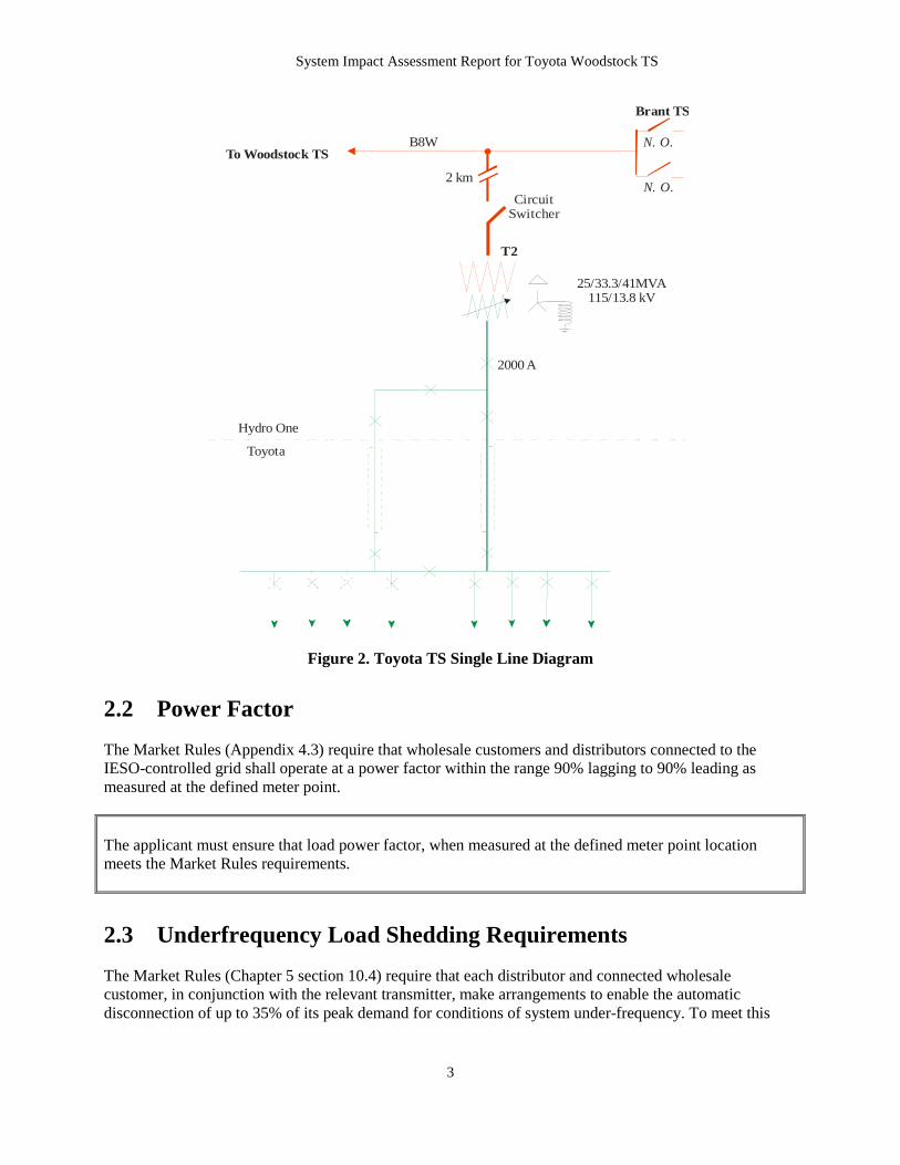
2.1 Connection Arrangement The proposed Toyota TS will consist of a single 115/13.8 kV, 25/41 MVA transformer that is to be connected to the 115 kV circuit B8W. The ultimate stage of the station will be a DESN with two transformers. The footprint for the station should be one that will accommodate the ultimate stage. The tap point would be approximately 5 km from Woodstock TS on 115 kV circuit B8W. A new 2 km double circuit 115 kV tap will provide the connection between the transformer-station-site on Toyota’s property and the 115 kV circuit B8W. The new 115 kV dual winding transformer will be connected to the IESO-controlled grid via one 115 kV circuit switcher. The transformer is configured with a delta winding on the high side and wye winding (neutral grounded via a 0.7 or 7.5 ohms reactor) on the low voltage side. The transformer is equipped with under-load tap changer located on the low voltage winding with a range of about ±2.13 kV that is to be achieved in 24 steps. The transformer impedance is 12% based on 25 MVA. The 2 km 115 kV line taps are to meet the following requirements:
• Nominal system voltage 115 kV • Maximum continuous operating voltage 127 kV • Maximum normal current 600 A
The transformer is to supply two 13.8 kV feeders. The LV breakers are rated for 2000 A with maximum operating voltage of 15 kV. Hydro One did not provide the short circuit interrupting capability for the LV breakers. Woodstock TS is an existing 50/83.3 MVA 115/28 kV station with one 21.6 MVAr 28.8 kV capacitor connected to one of the two LV buses. The new 21.6 MVAr 28.8 kV capacitor is to be connected to the other LV bus. Proposed Toyota TS single line diagram is shown in Figure 2.
System Impact Assessment Report for Toyota Woodstock TS
3
B8W
T2
Hydro One
2000 A
Circuit Switcher
25/33.3/41MVA115/13.8 kV
Toyota
N. O.
Brant TS
To Woodstock TSN. O.
2 km
Figure 2. Toyota TS Single Line Diagram
2.2 Power Factor The Market Rules (Appendix 4.3) require that wholesale customers and distributors connected to the IESO-controlled grid shall operate at a power factor within the range 90% lagging to 90% leading as measured at the defined meter point. The applicant must ensure that load power factor, when measured at the defined meter point location meets the Market Rules requirements.
2.3 Underfrequency Load Shedding Requirements The Market Rules (Chapter 5 section 10.4) require that each distributor and connected wholesale customer, in conjunction with the relevant transmitter, make arrangements to enable the automatic disconnection of up to 35% of its peak demand for conditions of system under-frequency. To meet this

System Impact Assessment Report for Toyota Woodstock TS
4
requirement an under frequency load shedding (UFLS) scheme must be installed at the station. The single line diagram does not show the presence of the UFLS scheme. The under frequency automatic load shedding should be provided by tripping feeder breakers to achieve:
• Automatic load shedding of 12% of station peak load at a nominal set point of 59.3 Hz and • Automatic load shedding of an additional 23% of station peak load at a nominal set point of 58.8
Hz, for a total load reduction of 35% of the total station load. The Connection Applicant is required to commit that UFLS will be installed at the station to meet the Market Rules requirements.
2.4 Voltage Reduction Facilities Requirements The Market Rules (Chapter 4 Appendix 4.3) requires that distributors connected to the IESO controlled grid with directly connected load facilities of aggregated rating of 20 MVA or more and the capability to regulate distribution voltage under load, shall install and maintain facilities to provide voltage reduction capability to achieve load reduction during periods when supply resources are limited. Voltage reduction capability represents the capability of reducing demand by lowering the customer voltage by 3% and 5% and having the controlling authority to be able to effect the voltage reduction within five minutes of receipt of the direction from the IESO. The Connection Applicant is required to commit to install voltage reduction capability that provides 3% and 5% voltage reduction within five minutes.
2.5 On-line Monitoring The Market Rules (Chapter 4 section 7.4) require that each transmitter shall provide the IESO on a continual basis with on-line monitored quantities as specified in Appendix 4.16. Hydro One must install all the equipment needed to monitor the information required by the IESO on a continuous basis. The IESO requires that the following quantities at Toyota TS be provided to the IESO on a continual basis via approved communication protocols:
1. The voltage on the high/low tension buses 2. The status of the bus tie breaker 3. The status of the transformer low voltage breakers 4. The status of the transformer high voltage disconnect switches 5. The real and reactive power flow through the transformer 6. The transformer tap position of the transformer
Hydro One is required to install all the equipment needed to continuously monitor the information that is required by the IESO. The IESO will finalize items to be monitored during the IESO Facility Registration Process.
System Impact Assessment Report for Toyota Woodstock TS
5
2.6 Protection Systems With respect to the protection and telecommunication requirements, the connection applicant must follow the Transmission System Code technical requirements for tapped transformer stations supplying load. The applicant has indicated that the station equipment and station control/protection were designed to meet the intent of the Transmission System Code. The applicant indicated that the transformer will be separated from the transmission system via a circuit switcher. The switcher is required to trip for local transformer faults and LV breaker failure. Independent inputs for the tripping of the interrupter and opening of the disconnect switch shall be provided. Protections that trip the interrupter shall simultaneously initiate opening of the disconnect switch portion of the interrupter. The protection systems associated with B8W are to be revised as required.
– End of Section –

System Impact Assessment Report for Toyota Woodstock TS
6
3. Data Verification The proposed new Toyota TS will be a single transformer station with one 25/41 MVA transformer. The high voltage circuit switcher is designed for a maximum continuous operating voltage of 138 kV and a continuous rating of 1200 A and an interrupting capability of 4000 A. Hydro One indicated that the maximum short circuit current at the tapping point of Toyota on B8W is 3180 A when supplied from the Buchanan end and 2160 A when supplied from the Burlington end. However, when the Woodstock area reinforcements go into service in 2010, the short circuit currents are expected to increase beyond the capability of this circuit switcher. Hydro One confirmed that a circuit switcher with acceptable fault interrupting capability will be installed at that time. The system performance standards listed in the Transmission System Code requires that the 13.8 kV system fault level not exceed 21 kA. This indicates that 13.8 kV equipments must be sized to interrupt 21 kA. Hydro One must ensure that the LV breakers proposed for installation at Toyota TS meet the interrupting capability as recommended by the Transmission System Code. A full description of the connection arrangement of the proposed Toyota TS is included in Section 2.1 of this report.
– End of Section –

System Impact Assessment Report for Toyota Woodstock TS
7
4. Fault Level Assessment The customer has advised that there is no generation or large synchronous motors connected to their distribution system. In general, radial loads do not have a large impact on the system fault levels, but a small contribution in short circuit currents can be observed due to the grounding of the transformers. In the case of Toyota TS the high voltage winding is ungrounded, hence line-to-ground faults occurring on the distribution side will have no impact on the short circuit levels.
– End of Section –
System Impact Assessment Report for Toyota Woodstock TS
8
5. Impact on System Reliability This connection assessment study concentrated on identifying the effect of the proposed load supply at Woodstock TS and Toyota TS on thermal loading of the transmission lines and system voltages for pre and post contingency situations.
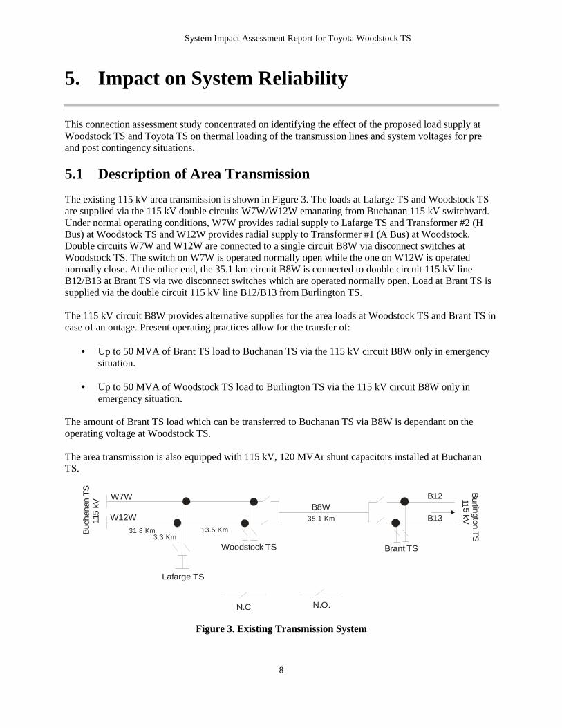
5.1 Description of Area Transmission The existing 115 kV area transmission is shown in Figure 3. The loads at Lafarge TS and Woodstock TS are supplied via the 115 kV double circuits W7W/W12W emanating from Buchanan 115 kV switchyard. Under normal operating conditions, W7W provides radial supply to Lafarge TS and Transformer #2 (H Bus) at Woodstock TS and W12W provides radial supply to Transformer #1 (A Bus) at Woodstock. Double circuits W7W and W12W are connected to a single circuit B8W via disconnect switches at Woodstock TS. The switch on W7W is operated normally open while the one on W12W is operated normally close. At the other end, the 35.1 km circuit B8W is connected to double circuit 115 kV line B12/B13 at Brant TS via two disconnect switches which are operated normally open. Load at Brant TS is supplied via the double circuit 115 kV line B12/B13 from Burlington TS. The 115 kV circuit B8W provides alternative supplies for the area loads at Woodstock TS and Brant TS in case of an outage. Present operating practices allow for the transfer of:
• Up to 50 MVA of Brant TS load to Buchanan TS via the 115 kV circuit B8W only in emergency situation.
• Up to 50 MVA of Woodstock TS load to Burlington TS via the 115 kV circuit B8W only in
emergency situation. The amount of Brant TS load which can be transferred to Buchanan TS via B8W is dependant on the operating voltage at Woodstock TS. The area transmission is also equipped with 115 kV, 120 MVAr shunt capacitors installed at Buchanan TS.
Buc
han
an T
S
115
kV
Burl in
gton T
S 11
5 kV
Brant TS
Lafarge TS
Woodstock TS
B12
B13W12W
W7W
N.C. N.O.
B8W
31.8 Km 13.5 Km
35.1 Km
3.3 Km
Figure 3. Existing Transmission System

System Impact Assessment Report for Toyota Woodstock TS
9
5.2 Load Forecasts The IESO forecasts the summer peak load at existing Woodstock TS, Lafarge TS, Ingersoll TS and Brantford TS and the load forecast at Toyota plant based on the operation records and Market Participants’ forecasts. The assumptions/sources for the forecast are:
1. As shown in IESO operation records, coincident summer peak load at Woodstock in 2006 was 89.4 MW. 8 MW load will be transferred to Ingersoll in 2007. The load growth at Woodstock is 5.1% to 2010 and 2.7% between 2010 and 2016.
2. Lafarge load forecast was provided by Market Participants. 3. Load at Toyota plant was provided by HO. 4. IESO records indicate that the coincident summer peak at Ingersoll was 79 MW in 2006. Load
growth is 3% to 2010 and 2% afterwards as provided by Market Participants. 8 MW load will be transferred from Woodstock to Ingersoll in 2007 and then will be transferred to proposed Woodstock East TS in 2010.
5. Load forecast for Brantford was provided by Market Participants. The load forecast for these stations as well as the station load capabilities are summarized in Table 1.
Table 1. Station Capability (MVA) and Load Forecast (MW)
*: data not available **: single transformer It should be noted that the loads at Woodstock TS and Brantford TS exceed the station load capability. Hydro One is planning to build Woodstock East TS to alleviate the load at the existing Woodstock TS. As indicated in the SIA study for Powerline TS (CAA ID 2005-196), load at Brantford is to be limited within the station capability and all the loads above the capability in that area will be supplied via Powerline TS.
5.3 Study Assumptions For this system impact study the modified summer 2006 base case was used. Based on the schedule and arrangement of load supply for Toyota plant provided by Hydro One, the following three cases were selected for the analysis:
Scenario I: Up to 15 MW load at Toyota factory supplied via LV feeders from Woodstock TS Scenario II: Scenario I with an additional 20 MVAr shunt capacitor bank installed at Woodstock TS Scenario III: Load at Toyota plant entirely supplied by the proposed Toyota TS
Simulations were performed for the loads shown in Table 2 and under the following assumptions:
Stations Capability 2006 2007 2008 2009 2010 2011 2012 2013 2014 2015
Woodstock 92 MVA 89.4 86.0 90.3 95.0 99.8 102.5 105.3 108.1 111.0 114.0 Lafarge N/A* 10 11 11 11 11 11 11 11 11 11 Toyota N/A** 0 8 15 25 25 25 25 25 25 25
Ingersoll 175 MVA 79.0 89.4 92.1 94.8 89.7 91.5 93.3 95.1 97.0 99.0
Brantford 173 MVA 172 176 180 184 188 191 194 197 201 204
System Impact Assessment Report for Toyota Woodstock TS
10
1) Loads at Lafarge, Woodstock and Toyota were scaled to 2007 level for Scenarios I and II and
2009 level for Scenario III shown in Table 1, 2) 8 MW of load from Woodstock TS was transferred to Ingersoll TS as indicated by Hydro One, 3) Loads at Lafarge, Woodstock and Toyota were modeled with a power factor of 0.9 at the delivery
point, 4) Existing 1 × 20 MVAr LV shunt capacitors at Woodstock TS was in service, 5) Existing 1 × 120 MVAr 115 kV shunt capacitors at Buchanan TS was in service.
Table 2. Load Level Used in Study (MW)
Stations Scenario I Scenario II Scenario III
Woodstock TS 94 94 95 Lafarge TS 11 11 11 Ingersoll TS 89.4 89.4 94.8 Toyota TS 0 0 25
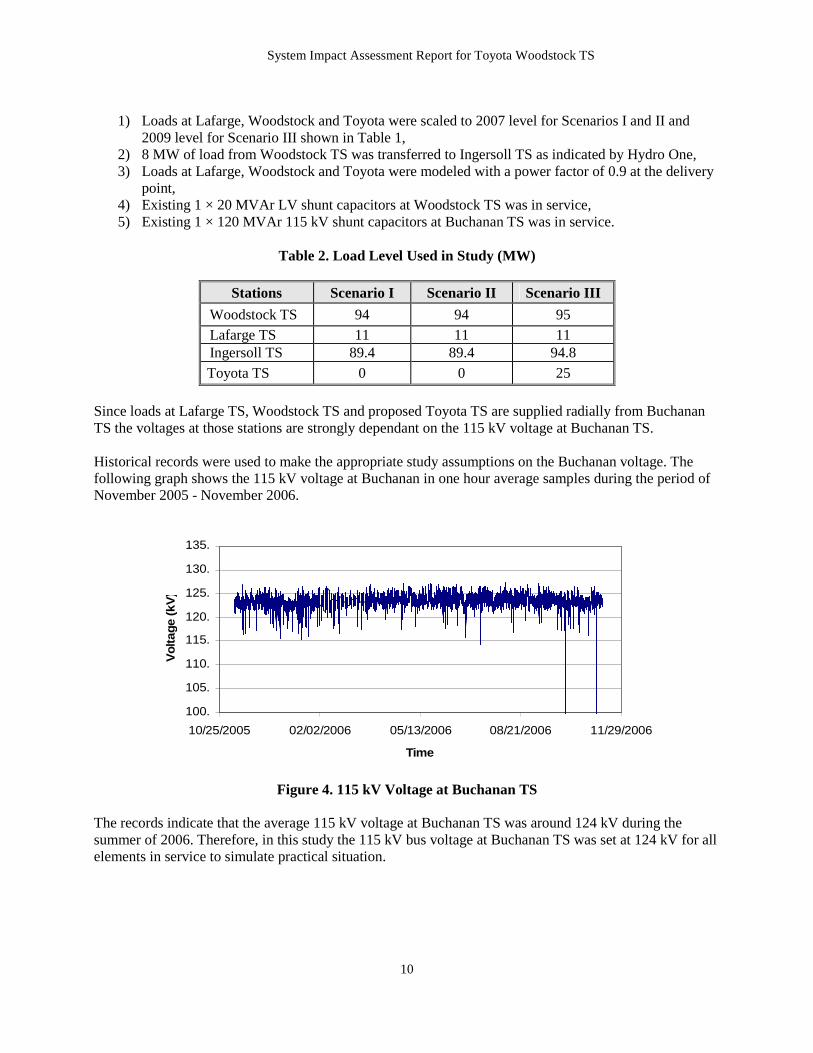
Since loads at Lafarge TS, Woodstock TS and proposed Toyota TS are supplied radially from Buchanan TS the voltages at those stations are strongly dependant on the 115 kV voltage at Buchanan TS. Historical records were used to make the appropriate study assumptions on the Buchanan voltage. The following graph shows the 115 kV voltage at Buchanan in one hour average samples during the period of November 2005 - November 2006.
100.
105.
110.
115.
120.
125.
130.
135.
10/25/2005 02/02/2006 05/13/2006 08/21/2006 11/29/2006
Time
Vol
tage
(kV
)
Figure 4. 115 kV Voltage at Buchanan TS
The records indicate that the average 115 kV voltage at Buchanan TS was around 124 kV during the summer of 2006. Therefore, in this study the 115 kV bus voltage at Buchanan TS was set at 124 kV for all elements in service to simulate practical situation.

System Impact Assessment Report for Toyota Woodstock TS
11
5.4 Voltage Analysis
5.4.1 Voltage Decline Studies The following IESO criteria must be satisfied when any new equipment is connected to the transmission system:
1. The pre-contingency voltage on 115 kV buses can not be less than113 kV. 2. The post-contingency voltage on 115 kV buses can not be less than 108 kV. 3. The voltage drop following a contingency can not exceed 10% pre-ULTC and 10% post-ULTC.
All the assumptions listed in section 5.3 were implemented in the base case model developed for these studies. Historical Records Presently, voltage performance at Woodstock TS is a concern for a contingency associated with W7W or W12W. This concern was confirmed in a detailed analysis of historical data described below. The next graph shows the voltage on 115 kV A bus and H Bus at Woodstock TS during the period of May 29 to June 4, 2006. Records show that for brief periods of time the voltage on 115 kV A bus at Woodstock TS was below 113 kV. In these instances, a comparison between the voltages at Woodstock TS buses A and H shows that the voltage at bus A was much lower than the voltage at H bus. The average voltage at H bus during the period of time is 127.3 kV which is higher than that of 124.4 kV at Buchanan TS. The voltage difference between A bus and H Bus could be attributed to W7W being out of service which would result in loads at Lafarge TS and Woodstock TS being supplied from W12W.
105.
110.
115.
120.
125.
130.
135.
05/27/2006 05/29/2006 05/31/2006 06/02/2006 06/04/2006 06/06/2006
Time
Vo
ltag
e (k
V)
A Bus H Bus
Figure 5. Voltage on 115 kV buses at Woodstock TS (May 29 – June 4, 2006) It can be seen from Figure 5 that the voltage was as low as 108 kV when W7W was not in service, which barely met the IESO’s criteria.

System Impact Assessment Report for Toyota Woodstock TS
12
Voltage Analysis Load flow studies have been carried out to examine the system voltage performance for the three selected scenarios under contingencies associated with W7W or W12W. Operating data and simulation results indicate that under normal operating conditions the voltage at H Bus was slightly lower than A Bus at Woodstock TS. Therefore, for pre-contingency voltage only H Bus voltage at Woodstock TS is presented and analyzed. Simulation results indicate that the loss of W7W or loss of W12W result in similar post-contingency system voltages. Therefore, only results with contingencies involved W12W are shown in this report. Scenario I: Voltage studies were performed for Scenario I to investigate the voltage performance as the Toyota load was added to Woodstock TS before the new 20 MVAr shunt capacitors are in service at Woodstock TS. The pre- and post-contingency voltages are shown in Table 3.
Table 3. Voltages Declines for Scenario I in 2007
Stations Buchanan Lafarge Woodstock Buses (kV) 115 115 13.8 115 27.6 Pre-contingency (kV) 123.9 118.5 13.5 116.9 28.0
Pre-ULTC (kV) 123.7 113.1 12.8 109.4 24.7 Voltage Decline (%) 0.2 4.6 5.2 6.4 11.8 Post-ULTC (kV) 123.3 110.4 12.5 105.8 27.6
Post-Contingency
Voltage Decline (%) 0.5 6.8 7.4 9.5 1.4 Study results show that the post-contingency voltage at Woodstock TS is only 105.8 kV which is under the minimum required operating voltage of 108 kV. To improve the post-contingency voltage to an acceptable level some amount of load must be rejected at Woodstock TS. Simulations were performed to determine the amount of load needed to be curtailed under contingency involved W7W or W12W. The results indicated that the combined load at Woodstock TS and Lafarge CTS must be limited to 100 MW so that the voltage at Woodstock TS will remain within acceptable levels. With the initial load at Toyota plant supplied from Woodstock TS the 2007 peak load is projected to be 94 MW. Before Toyota TS and new shunt capacitor at Woodstock TS come to service, the load at Woodstock TS must be limited to 89 MW or the combined load at Woodstock TS and Lafarge CTS must be limited to 100 MW. Before the new shunt capacitor is installed loads in excess of 89MW at Woodstock TS would have to be curtailed under contingency associated with W7W or W12W. Or may require to operate the station with bus-tie open, when load is greater than 89 MW.
System Impact Assessment Report for Toyota Woodstock TS
13
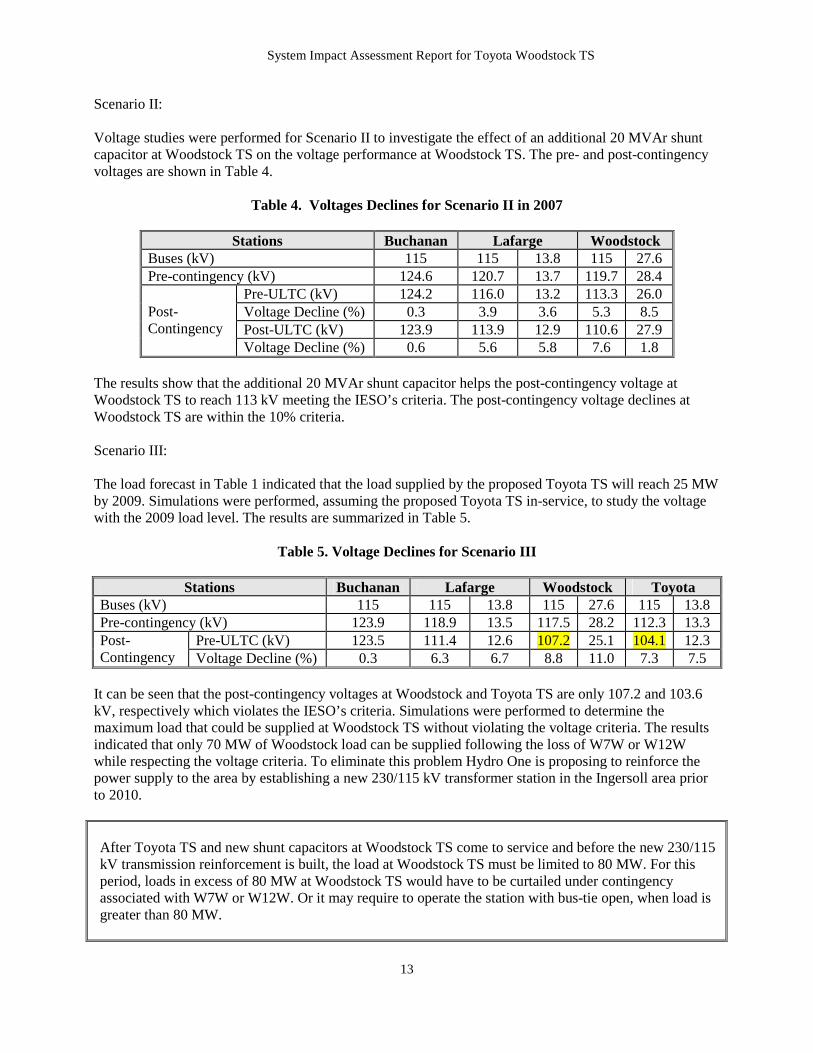
Scenario II: Voltage studies were performed for Scenario II to investigate the effect of an additional 20 MVAr shunt capacitor at Woodstock TS on the voltage performance at Woodstock TS. The pre- and post-contingency voltages are shown in Table 4.
Table 4. Voltages Declines for Scenario II in 2007
Stations Buchanan Lafarge Woodstock Buses (kV) 115 115 13.8 115 27.6 Pre-contingency (kV) 124.6 120.7 13.7 119.7 28.4
Pre-ULTC (kV) 124.2 116.0 13.2 113.3 26.0 Voltage Decline (%) 0.3 3.9 3.6 5.3 8.5 Post-ULTC (kV) 123.9 113.9 12.9 110.6 27.9
Post-Contingency
Voltage Decline (%) 0.6 5.6 5.8 7.6 1.8 The results show that the additional 20 MVAr shunt capacitor helps the post-contingency voltage at Woodstock TS to reach 113 kV meeting the IESO’s criteria. The post-contingency voltage declines at Woodstock TS are within the 10% criteria. Scenario III: The load forecast in Table 1 indicated that the load supplied by the proposed Toyota TS will reach 25 MW by 2009. Simulations were performed, assuming the proposed Toyota TS in-service, to study the voltage with the 2009 load level. The results are summarized in Table 5.
Table 5. Voltage Declines for Scenario III
Stations Buchanan Lafarge Woodstock Toyota Buses (kV) 115 115 13.8 115 27.6 115 13.8 Pre-contingency (kV) 123.9 118.9 13.5 117.5 28.2 112.3 13.3
Pre-ULTC (kV) 123.5 111.4 12.6 107.2 25.1 104.1 12.3 Post-Contingency Voltage Decline (%) 0.3 6.3 6.7 8.8 11.0 7.3 7.5
It can be seen that the post-contingency voltages at Woodstock and Toyota TS are only 107.2 and 103.6 kV, respectively which violates the IESO’s criteria. Simulations were performed to determine the maximum load that could be supplied at Woodstock TS without violating the voltage criteria. The results indicated that only 70 MW of Woodstock load can be supplied following the loss of W7W or W12W while respecting the voltage criteria. To eliminate this problem Hydro One is proposing to reinforce the power supply to the area by establishing a new 230/115 kV transformer station in the Ingersoll area prior to 2010. After Toyota TS and new shunt capacitors at Woodstock TS come to service and before the new 230/115 kV transmission reinforcement is built, the load at Woodstock TS must be limited to 80 MW. For this period, loads in excess of 80 MW at Woodstock TS would have to be curtailed under contingency associated with W7W or W12W. Or it may require to operate the station with bus-tie open, when load is greater than 80 MW.

System Impact Assessment Report for Toyota Woodstock TS
14
5.4.2 Shunt Capacitor Switching Studies The requirements for abrupt voltage changes due to capacitor switching are listed in Appendix 4.4 in Market Rules as follows:
• Voltage changes shall not normally exceed 4% of steady state rms for capacitor switching operations.
Presently Woodstock TS has one 21.6MVAr 28.8kV capacitor. Historic operating records indicated a voltage change of 1.7% at HV buses but a change of 4.3% at LV bus for capacitor switching. Figure 6 shows the voltage changes on LV bus at Woodstock TS was 4.3% due to shunt capacitor switching. Records were sampled every two seconds during the period of 08:19:30 to 08:19:44 on Aug. 01, 2006.
27.6
27.8
28.0
28.2
28.4
28.6
28.8
29.0
08:19:28 08:19:32 08:19:36 08:19:41 08:19:45
Time
Vo
ltag
e (k
V)
Figure 6. Voltage changes on LV bus at Woodstock TS (Aug. 01, 2006)
Switching study was carried out to investigate the effect of the existing and new LV shunt capacitor banks on the voltage changes at Woodstock TS. The study was performed using the same base case as used in previous study. IESO Transmission Assessment Criteria specifies that voltage-dependant model should be used for capacitor switching studies. The voltages at LV bus and HV buses (A and H) at Woodstock TS were monitored and the results are summarized in Table 6.
Table 6. Voltage Changes at Woodstock TS for Shunt Switching
LV HV A Bus HV H Bus Scenario Initial Condition PRE POST % PRE POST % PRE POST % 0 MVAr I/S 28.0 29.2 4.3 114.8 116.9 1.8 114.0 116.2 1.9
II 20 MVAr I/S 28.0 29.2 4.3 117.7 119.8 1.8 116.9 119.0 1.8 0 MVAr I/S 28.1 29.4 4.6 109.6 111.8 2.0 111.4 113.6 2.0
III 20 MVAr I/S 27.7 29.0 4.7 112.7 114.7 1.8 114.5 116.6 1.8

System Impact Assessment Report for Toyota Woodstock TS
15
As shown in Table 5, the HV busses at Woodstock TS exhibit voltages changes less than 4% which meets Market Rules requirements. However, similar with the operating records shown in Figure 6, the simulated LV bus has voltage changes greater than 4%.
5.5 Thermal Study
This section covers an investigation of thermal capability of the 115 kV circuits W7W, W12W and B8W to supply the Woodstock area load. Circuits W7W, W12W and B8W have identical ratings as shown in Table 7. The continuous rating was calculated 4 km wind speed and 35˚ daytime sheltered.
Table 7. 115 kV Circuit Ratings
Continuous Rating 15 Minutes LTR A MVA@115 kV A MVA@115kV Pre-Load (%)
783 156 50 751 150 75 736 147 85
530 106
720 143 95
The same base case of Scenario III was used for the thermal capability study as it was used for the voltage assessment. The results indicate that power flowing on W7W and W12W from Buchanan TS is about 64 MVA each which is well within the circuit continuous rating. For a contingency associated with W7W or W12W simulation for scenarios III was performed with 70 MW load at Woodstock TS. It was found that the flow on the remaining circuit from Buchanan TS is 121 MVA. Therefore, it can be concluded that there is no thermal concern identified on the 115 kV circuits with the proposed Toyota TS. It should be noted that the line disconnect switches associated with W7W & W12W at Buchanan terminal are rated at 600 A each which is about 125 MVA at 120 kV. Under a contingency associated with W7W or W12W the disconnect switch on the remaining circuit will be at a risk of overloading.
5.6 Motor Starting Study 5.6.1 Motor Information Hydro One indicated the Toyota plant will be equipped with several induction motors. The motor starting study was carried out in this section based on the following motor information provided by Hydro One. Frequency of starting 5 Chillers (each has 2* 700 HP motors) Each chiller is started 2 times per day. No chillers are started simultaneously. When a chiller is started, both motors are not started at the same time. 4 Air compressors (1*1250 HP & 3*1000 HP) Two air compressors will be running normally with 3 running at peak periods.

System Impact Assessment Report for Toyota Woodstock TS
16
The air compressors would be started 4 times per day. The 1250 HP is always on when chillers are running Induction Motor Data 700HP (Full Load Current=77A @4.16 kV), and (Locked Rotor Current =462 A at 4.16 kV) 1000HP (Full Load Current=121A @4.16 kV), and (Locked Rotor Current =785 A at 4.16 kV) 1250HP (Full Load Current= 148A @4.16 kV), and (Locked Rotor Current =963 A at 4.16 kV)
5.6.2 Motor Starting Study Assumptions The same modified summer 2006 base case was used in the study. Based on the schedule and arrangement of load supply for Toyota plant provided by Hydro One, the following assumptions were used in the analysis:
1. No new shunt capacitor at Woodstock TS 2. 8 MW load at Toyota TS 3. Start-up of the biggest motor (1250 HP) 4. An impedance of 5% on a 5 MVA base for the 13.8/4.16 kV transformer 5. Locked rotor current used as starting current 6. Motor starting up at a power factor of 0.3
5.6.3 Motor Starting Study Results The study results for motor starting are shown in Table 8.
Table 8. Motor Starting Study Results Bus Pre-Start Voltage (kV) Start-up Voltage (kV) Voltage Dip (%)
Toyota 115 kV 113.5 112.2 1.15 Toyota 13.8 kV 13.7 13.1 4.40 Toyota 4.16 kV 4.14 3.65 11.83
Results show that the start of the 1250 HP motor will reduce 115 kV voltage from 113.5 kV down to 112.2 kV (1.15 % drop) and 4.16 kV voltage to 3.65 kV (11.83 % drop). Low post-contingency voltage problems were identified in Section 4.2. Simulations were performed for the motor start-up with a contingency associated with W7W or W12W. The results show that the motor cannot start due to low post-contingency voltage. It should be noted that the motors at Toyota plant can only be started with both W7W and W12W in service prior to the in-service of Hydro One’s WATR project.
5.7 Summary Voltage problems at Woodstock TS were identified in this study. The findings of analysis are summarized as follows:

System Impact Assessment Report for Toyota Woodstock TS
17
1. Before Toyota TS and new shunt capacitors at Woodstock TS come into service, the post-contingency voltage at Woodstock TS is under the minimum required operating voltage of 108 kV. The combined load at Woodstock TS and Lafarge GTS must be limited to 100 MW so that the voltage at Woodstock TS will remain within acceptable levels. Or may require to operate the station with bus-tie open, when the combined load at Woodstock TS and Lafarge CTS is greater than 100 MW.
2. Before Toyota TS is in service and with additional 20 MVAr shunt capacitors installed at
Woodstock TS, there are no voltage concerns at Woodstock TS.
3. After Toyota TS comes into service, the post-contingency voltage at Toyota TS is below the minimum required operating voltage of 108 kV. The combined load at Woodstock TS and Lafarge CTS must be limited to 91 MW so that the voltage at Toyota TS will remain within acceptable levels. Or may require to operate the Woodstock TS with bus-tie open, when combined load at Woodstock TS and Lafarge CTS is greater than 91 MW.
4. The LV voltage changes at Woodstock TS slightly exceed 4% of steady state rms for shunt
capacitor switching operations.
5. It should be noted that the motors at Toyota plant can only be started with both W7W and W12W in service prior to the in-service of Hydro One’s WATR project.
6. There is no thermal concern identified for the proposed project.
7. Under a contingency associated with W7W or W12W the disconnect switch on the remaining
circuit will be at a risk of overloading.
Voltage performance in Woodstock area is an on-going problem and limits the power supply capability for that area. The addition of load at Toyota factory will make the situation even worse. The addition of a 20 MVAr shunt capacitor at Woodstock TS will resolve the voltage concern identified at Woodstock TS temporally. Hydro One has proposed to increase the power supply capability in Woodstock area by reinforcing the local transmission system with 230 kV power supply. The Woodstock Area Transmission System Reinforcement project is assessed in a separate SIA study (CAA ID 2006-253).
– End of Report –