SYSTEM FOR CONVERTING ELECTROMAGNETIC RADIATION …
17
A Practical Guide to ‘Free Energy’ Devices Device Patent No 24: Last updated: 25th February 2007 Author: Patrick J. Kelly This patent shows a system for converting Zero-Point Energy into conventional electrical power. Patent US 5,590,031 31st December 1996 Inventors: Franklin Mead & Jack Nachamkin SYSTEM FOR CONVERTING ELECTROMAGNETIC RADIATION ENERGY TO ELECTRICAL ENERGY ABSTRACT A system is disclosed for converting high-frequency zero-point electromagnetic radiation energy to electrical energy. The system includes a pair of dielectric structures which are positioned near each other and which receive incident zero-point electromagnetic radiation. The volumetric sizes of the structures are selected so that they resonate at a frequency of the incident radiation. The volumetric sizes of the structures are also slightly different so that the secondary radiation emitted from them at resonance, interferes with each other producing a beat frequency radiation which is at a much lower frequency than that of the incident radiation and which is amenable to conversion to electrical energy. An antenna receives the beat frequency radiation. The beat frequency radiation from the antenna is transmitted to a converter via a conductor or waveguide and converted to electrical energy having a desired voltage and waveform. US Patent References: 3882503 May., 1975 Gamara 343/100. 4725847 Feb., 1988 Poirier 343/840. 5008677 Apr., 1991 Trigon et al. 342/17. Description: BACKGROUND OF THE INVENTION The invention relates generally to conversion of electromagnetic radiation energy to electrical energy, and, more particularly, to conversion of high frequency bandwidths of the spectrum of a type of radiation known as ‘zero-point electromagnetic radiation’ to electrical energy. The existence of zero-point electromagnetic radiation was discovered in 1958 by the Dutch physicist M. J. Sparnaay. Mr. Sparnaay continued the experiments carried out by Hendrik B. G. Casimir in 1948 which showed the existence of a force between two uncharged parallel plates which arose from electromagnetic radiation surrounding the plates in a vacuum. Mr. Sparnaay discovered that the forces acting on the plates arose from not only thermal radiation but also from another type of radiation now known as classical electromagnetic zero-point radiation. Mr. Sparnaay determined that not only did the zero-point electromagnetic radiation exist in a vacuum but also that it persisted even at a temperature of absolute zero. Because it exists in a vacuum, zero-point radiation is homogeneous and isotropic as well as ubiquitous. In addition, since zero-point radiation is also invariant with respect to Lorentz transformation, the zero-point radiation spectrum has the characteristic that the intensity of the radiation at any frequency is proportional to the cube of that frequency. Consequently, the intensity of the radiation increases without limit as the frequency increases resulting in an infinite energy density for the radiation spectrum. With the introduction of the zero-point radiation into the classical electron theory, a vacuum at a temperature of absolute zero is no longer considered empty of all electromagnetic fields. Instead, the vacuum is now considered as filled with randomly fluctuating fields having the zero-point radiation spectrum. The special characteristics of the zero-point radiation which are that it has a virtually infinite energy density and that it is ubiquitous (even
Transcript of SYSTEM FOR CONVERTING ELECTROMAGNETIC RADIATION …

A Practical Guide to ‘Free Energy’ Devices Device Patent No 24: Last updated: 25th February 2007 Author: Patrick J. Kelly This patent shows a system for converting Zero-Point Energy into conventional electrical power. Patent US 5,590,031 31st December 1996 Inventors: Franklin Mead & Jack Nachamkin
SYSTEM FOR CONVERTING ELECTROMAGNETIC RADIATION
ENERGY TO ELECTRICAL ENERGY ABSTRACT A system is disclosed for converting high-frequency zero-point electromagnetic radiation energy to electrical energy. The system includes a pair of dielectric structures which are positioned near each other and which receive incident zero-point electromagnetic radiation. The volumetric sizes of the structures are selected so that they resonate at a frequency of the incident radiation. The volumetric sizes of the structures are also slightly different so that the secondary radiation emitted from them at resonance, interferes with each other producing a beat frequency radiation which is at a much lower frequency than that of the incident radiation and which is amenable to conversion to electrical energy. An antenna receives the beat frequency radiation. The beat frequency radiation from the antenna is transmitted to a converter via a conductor or waveguide and converted to electrical energy having a desired voltage and waveform. US Patent References: 3882503 May., 1975 Gamara 343/100. 4725847 Feb., 1988 Poirier 343/840. 5008677 Apr., 1991 Trigon et al. 342/17. Description: BACKGROUND OF THE INVENTION The invention relates generally to conversion of electromagnetic radiation energy to electrical energy, and, more particularly, to conversion of high frequency bandwidths of the spectrum of a type of radiation known as ‘zero-point electromagnetic radiation’ to electrical energy. The existence of zero-point electromagnetic radiation was discovered in 1958 by the Dutch physicist M. J. Sparnaay. Mr. Sparnaay continued the experiments carried out by Hendrik B. G. Casimir in 1948 which showed the existence of a force between two uncharged parallel plates which arose from electromagnetic radiation surrounding the plates in a vacuum. Mr. Sparnaay discovered that the forces acting on the plates arose from not only thermal radiation but also from another type of radiation now known as classical electromagnetic zero-point radiation. Mr. Sparnaay determined that not only did the zero-point electromagnetic radiation exist in a vacuum but also that it persisted even at a temperature of absolute zero. Because it exists in a vacuum, zero-point radiation is homogeneous and isotropic as well as ubiquitous. In addition, since zero-point radiation is also invariant with respect to Lorentz transformation, the zero-point radiation spectrum has the characteristic that the intensity of the radiation at any frequency is proportional to the cube of that frequency. Consequently, the intensity of the radiation increases without limit as the frequency increases resulting in an infinite energy density for the radiation spectrum. With the introduction of the zero-point radiation into the classical electron theory, a vacuum at a temperature of absolute zero is no longer considered empty of all electromagnetic fields. Instead, the vacuum is now considered as filled with randomly fluctuating fields having the zero-point radiation spectrum. The special characteristics of the zero-point radiation which are that it has a virtually infinite energy density and that it is ubiquitous (even

present in outer space) make it very desirable as an energy source. However, because high energy densities exist at very high radiation frequencies and because conventional methods are only able to convert or extract energy effectively or efficiently only at lower frequencies at which zero-point radiation has relatively low energy densities, effectively tapping this energy source has been believed to be unavailable using conventional techniques for converting electromagnetic energy to electrical or other forms of easily usable energy. Consequently, zero-point electromagnetic radiation energy which may potentially be used to power interplanetary craft as well as provide for society's other needs has remained unharnessed. There are many types of prior art systems which use a plurality of antennas to receive electromagnetic radiation and provide an electrical output from them. An example of such a prior art system is disclosed in U.S. Pat. No. 3,882,503 to Gamara. The Gamara system has two antenna structures which work in tandem and which oscillate by means of a motor attached to them in order to modulate the radiation reflected from the antenna surfaces. The reflecting surfaces of the antennas are also separated by a distance equal to a quarter wavelength of the incident radiation. However, the Gamara system does not convert the incident radiation to electrical current for the purpose of converting the incident electromagnetic radiation to another form of readily usable energy. In addition, the relatively large size of the Gamara system components make it unable to resonate at and modulate very high frequency radiation. What is therefore needed is a system which is capable of converting high frequency electromagnetic radiation energy into another form of energy which can be more readily used to provide power for transportation, heating, cooling as well as various other needs of society. What is also needed is such a system which may be used to provide energy from any location on earth or in space. SUMMARY OF THE INVENTION It is a principle object of the present invention to provide a system for converting electromagnetic radiation energy to electrical energy. It is another object of the present invention to provide a system for converting electromagnetic radiation energy having a high frequency to electrical energy. It is another object of the present invention to provide a system for converting zero-point electromagnetic radiation energy to electrical energy. It is another object of the present invention to provide a system for converting electromagnetic radiation energy to electrical energy which may used to provide such energy from any desired location on earth or in space. It is another object of the present invention to provide a system for converting electromagnetic radiation energy to electrical energy having a desired waveform and voltage. It is an object of the present invention to provide a miniaturised system for converting electromagnetic radiation energy to electrical energy in order to enhance effective utilisation of high energy densities of the electromagnetic radiation. It is an object of the present invention to provide a system for converting electromagnetic radiation energy to electrical energy which is simple in construction for cost effectiveness and reliability of operation. Essentially, the system of the present invention utilises a pair of structures for receiving incident electromagnetic radiation which may be propagating through a vacuum or any other medium in which the receiving structures may be suitably located. The system of the present invention is specifically designed to convert the energy of zero-point electromagnetic radiation; however, it may also be used to convert the energy of other types of electromagnetic radiation. The receiving structures are preferably composed of dielectric material in order to diffract and scatter the incident electromagnetic radiation. In addition, the receiving structures are of a volumetric size selected to enable the structures to resonate at a high frequency of the incident electromagnetic radiation based on the parameters of frequency of the incident radiation and propagation characteristics of the medium and of the receiving structures. Since zero-point radiation has the characteristic that its energy density increases as its frequency increases, greater amounts of electromagnetic energy are available at higher frequencies. Consequently, the size of the structures are preferably miniaturised in order to produce greater amounts of energy from a system located within a space

or area of a given size. In this regard, the smaller the size of the receiving structures, the greater the amount of energy that can be produced by the system of the present invention. At resonance, electromagnetically induced material deformations of the receiving structures produce secondary fields of electromagnetic energy therefrom which may have evanescent energy densities several times that of the incident radiation. The structures are of different sizes so that the secondary fields arising therefrom are of different frequencies. The difference in volumetric size is very small so that interference between the two emitted radiation fields, and the receiving structures at the two different frequencies produces a beat frequency radiation which has a much lower frequency than the incident radiation. The beat frequency radiation preferably is at a frequency which is sufficiently low that it may be relatively easily converted to usable electrical energy. In contrast, the incident zero-point radiation has its desirable high energy densities at frequencies which are so high that conventional systems for converting the radiation to electrical energy either cannot effectively or efficiently so convert the radiation energy or simply cannot be used to convert the radiation energy for other reasons. The system of the present invention also includes an antenna which receives the beat frequency radiation. The antenna may be a conventional metallic antenna such as a loop or dipole type of antenna or a rf cavity structure which partially encloses the receiving structures. The antenna feeds the radiation energy to an electrical conductor (in the case of a conventional dipole or comparable type of antenna) or to a waveguide (in the case of a rf cavity structure). The conductor or waveguide feeds the electrical current (in the case of the electrical conductor) or the electromagnetic radiation (in the case of the waveguide) to a converter which converts the received energy to useful electrical energy. The converter preferably includes a tuning circuit or comparable device so that it can effectively receive the beat frequency radiation. The converter may include a transformer to convert the energy to electrical current having a desired voltage. In addition, the converter may also include a rectifier to convert the energy to electrical current having a desired waveform. BRIEF DESCRIPTION OF THE DRAWINGS
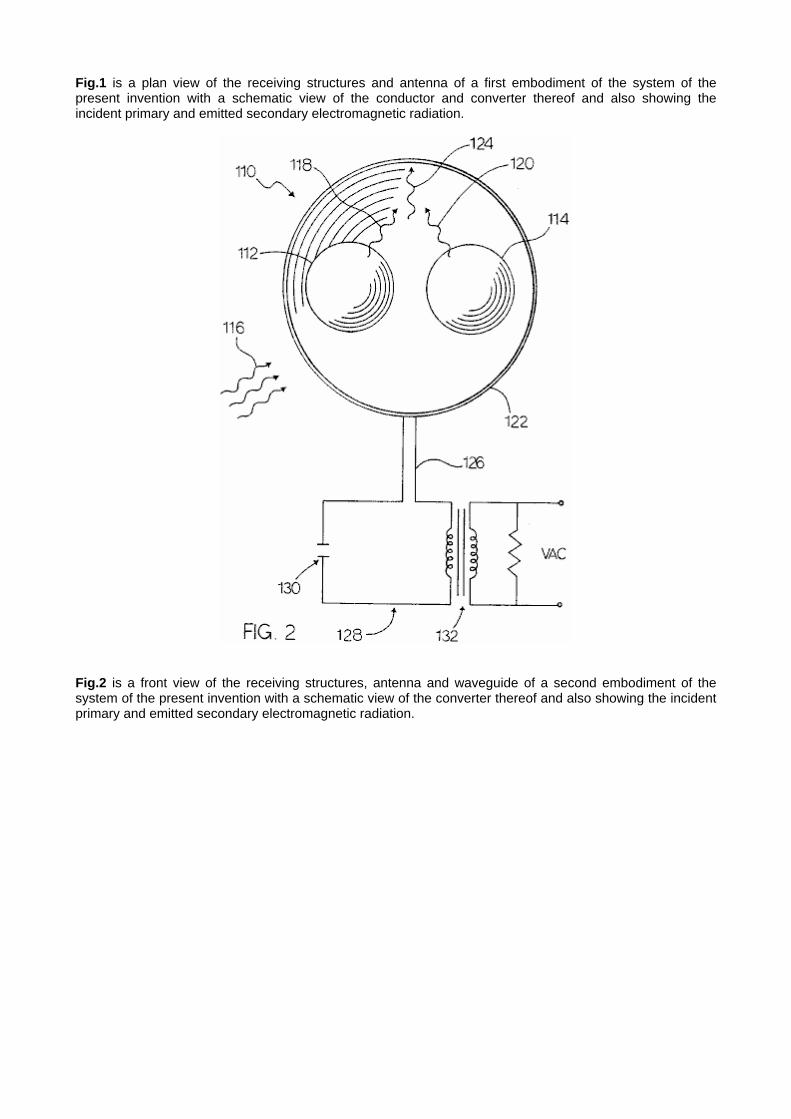
Fig.1 is a plan view of the receiving structures and antenna of a first embodiment of the system of the present invention with a schematic view of the conductor and converter thereof and also showing the incident primary and emitted secondary electromagnetic radiation.
Fig.2 is a front view of the receiving structures, antenna and waveguide of a second embodiment of the system of the present invention with a schematic view of the converter thereof and also showing the incident primary and emitted secondary electromagnetic radiation.

Fig.3 is a perspective view of the receiving structures, antenna and waveguide of the second embodiment shown in Fig.2 with a schematic view of the converter thereof and also showing the incident primary and emitted secondary electromagnetic radiation.

Fig.4 is a front view of the substrate and a plurality of pairs of the receiving structures and a plurality of antennas of a third embodiment of the system of the present invention with a schematic view of the conductor and converter thereof and also showing the incident primary and emitted secondary electromagnetic radiation.
Fig.5 is a top view of some of the components of the third embodiment of the system of the present invention showing two of the plurality of pairs of receiving structures and two of the plurality of antennas mounted on the substrate.

Fig.6 is a diagram of a receiving structure of the system of the present invention showing an incident electromagnetic plane wave impinging on the receiving structure and illustrating the directions of the electric and magnetic field vectors thereof.
Fig.7 is a diagram of a spherical co-ordinate system as used in the formulas utilised in the system of the present invention.

Fig.8 is a graph showing an imaginary rho parameter plotted against a real rho parameter illustrating the values thereof at resonance as well as values thereof at other than resonance.
Fig.9 is a graph showing a portion of the graphical representation shown in Fig.8 illustrating the real and imaginary rho values at or near a single resonance.

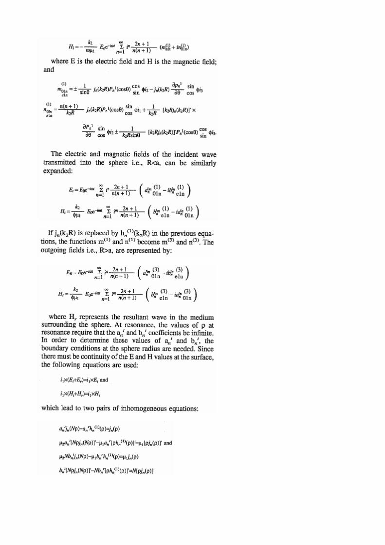
DETAILED DESCRIPTION OF THE PREFERRED EMBODIMENT Referring to the drawings, a first embodiment of the present invention is generally designated by the numeral 10. The system 10 includes a first and second means for receiving 12 and 14 incident electromagnetic radiation 16. The means for receiving 12 and 14 are preferably a pair of spherical structures 12 and 14 which are preferably composed of a dielectric material. Alternatively, the spheres 12 and 14 may be cubical structures or any other suitable shape. The spheres 12 and 14 may be mounted on a suitable foundation by any suitable mounting means (not shown), or spheres 12 and 14 may be suspended from a suitable foundation by any suitable suspension means (not shown). The spheres 12 and 14 are preferably composed of a dielectric material. The dielectric spheres 12 and 14 scatter and concentrate electromagnetic waves. At very sharply defined frequencies, the spheres 12 and 14 will have resonances wherein the internal energy densities can be five orders of magnitude larger than the energy density of the incident electromagnetic field driving the spheres 12 and 14. At resonance, the electromagnetic stresses, equivalent to pressures proportional to the energy density, can cause material deformation of the spheres 12 and 14 which produce a secondary electromagnetic field. The spheres 12 and 14 are preferably positioned proximal to each other, as shown in Fig.1. Although the proximity of the spheres to each other will adversely affect the resonances, the very high "Q"s of the isolated-sphere resonances results in such adverse affect being relatively small. However, the proximity of the spheres 12 and 14 allows the spheres to interact electromechanically which increases the magnitude of the secondary radiation emitted from them. The electromagnetic radiation incident upon the spheres 12 and 14 which drives the spheres to resonance is preferably zero-point radiation 16. However, other types of electromagnetic radiation may also be used to drive the spheres 12 and 14, if desired. The effect of a dielectric sphere such as 12 or 14 on an incident electromagnetic radiation such as a plane wave thereof is shown in Fig.6. The plane wave propagates in the z axis direction and is diffracted by the sphere 12 resulting in scattering thereof. This scattering is commonly known as Mie scattering. The incident radiation wave has an electric vector component which is linearly polarised in the x axis direction and a magnetic vector component which is linearly polarised in the y axis direction. An electromagnetic wave incident upon a structure produces a forced oscillation of free and bound charges in synch with the primary electromagnetic field of the incident electromagnetic wave. The movements of the charges produce a secondary electromagnetic field both inside and outside the structure. The secondary electromagnetic radiation comprising this secondary electromagnetic field is shown in Fig.1 and designated by the numerals 18 and 20. An antenna which is shown simply as a loop antenna but may also be a dipole or any other suitable type of antenna, is also shown in Fig.1 and designated by the numeral 22. The non-linear mutual interactions of the spheres produces interference between the secondary electromagnetic radiation 18 and 20 produces a beat frequency radiation 24 which is preferably at a much lower frequency than the primary radiation 16. It is this beat frequency radiation 24 which is desired for conversion into electrical energy because it preferably is within the frequency range of rf radiation which may be converted into electrical energy by generally conventional systems. Thus, the radiation 24 received by the antenna 22 is fed via an electrical conductor 26 to a means for converting the beat frequency radiation 24 to electrical energy. This means for converting is designated by the numeral 28 and preferably includes a tuning capacitor 30 and a transformer 32 and a rectifier (preferably a diode) 34. Instead of including the capacitor 30, transformer 32 and rectifier 34, the converter 28 may alternatively include an rf receiver of any suitable type. The resultant field at any point is the vector sum of the primary and secondary fields. For the equations that follow, the structure receiving the incident plane wave is a sphere of radius a having a propagation constant k1 positioned in an infinite, homogeneous medium having a propagation constant k2. The incident plane wave propagates in the z axis direction and is as shown in Fig.6. The spherical co-ordinate system used for the vector spherical wave functions is shown in Fig.7. Note: As this patent contains so many non-standard keyboard characters, the remainder of this document is produced using direct images of the original text.