
System Cabinets 42U 1280 mm System Cabinet Guide
35
Transcript of System Cabinets 42U 1280 mm System Cabinet Guide


Contents
Preparing to install the system cabinet ....................................................... 4System cabinet features ............................................................................................... 4
Required tools and equipment ..................................................................................... 6
Space requirements and system cabinet dimensions ................................................... 6
Supported PDU types and specifications .................................................................... 8
Unpacking the system cabinet ..................................................................... 9Installing a system cabinet ......................................................................... 10
Installing the cabinet interconnect kit ....................................................................... 10
Installing the bolt-down kit ....................................................................................... 15
Installing additional support rails .............................................................................. 16
Installing equipment in the system cabinet ............................................................... 18
Powering on the system cabinet ................................................................................ 19
Replacing PDUs .......................................................................................... 21Reversing the system cabinet front door .................................................. 22
Removing the illuminated badge ............................................................................... 23
Removing the system cabinet door ........................................................................... 24
Moving the badge power supply and cabling ............................................................ 24
Reversing the door hinge and lock catch ................................................................... 27
Reinstalling the door and illuminated badge ............................................................. 29
Reinstalling the system cabinet door ............................................................. 29
Reinstalling the illuminated badge ................................................................ 30
Copyright information ............................................................................... 31Trademark information ............................................................................. 32How to send comments about documentation and receive update
notifications ............................................................................................ 33Index ............................................................................................................. 34
Table of Contents | 3

Preparing to install the system cabinet
Before installing the system cabinet, you should familiarize yourself with its features. You must alsoverify that your site can support the system cabinet, move it to the desired location, and then unpackit.
System cabinet featuresThe system cabinet consists of side panels, front and rear doors, an optional bolt-down kit, anoptional interconnect kit, PDUs for your equipment, and an integrated cable management system.
Feature Description
Side panels System cabinets have lockable, removable, andinterchangeable side panels.
Perforated front and rear doors System cabinets have removable front and reardoors with a quick release mechanism. Thefront door is reversible, and the rear doors aresplit. Both doors are perforated for cooling.
Common key This key unlocks the front doors, rear doors,and side panels.
Spares kit This kit is inside the system cabinet, attached tothe cabinet door. It contains the followingcomponents:
• Four 10-32 x 0.75 inch Phillips pilot screws
• Four 10-32 cage nuts
• One cage nut insertion tool
• Two master key copies
Cable access Cable pass-throughs are built into the top andbottom of the cabinet, as well as between thebottom of the rear door and the frame.
Cable management Cable management hook and loop strapping isattached to the frame of the system cabinet atequal intervals.
Support rails The number of support rails you receivedepends on your configuration. The emptysystem cabinet is shipped with no support railsinstalled.
• For configured system cabinets, one fixedrail kit is shipped with the system cabinet tosupport the 80xx, FAS8200, and DS4486rear hold-down brackets.
• Quick-ship system cabinets do not includethe additional fixed rail kit.
4

Feature Description
Blanking panels The number and size of blanking panels youreceive depends on your configuration. Theempty system cabinet is shipped with noblanking panels installed.
Bolt-down kit This optional kit enables you to secure thesystem cabinet to the data center floor. The kit itis not intended for seismic stability.
• Four bolt-down brackets
• Four spacer brackets
• Six M8x20 mm hex head bolts and washers
Interconnect kit This optional kit enables you to connectmultiple system cabinets to each other.
• Interconnect brackets
◦ One set of four interconnect brackets forconnecting the system cabinets with sidepanels on
◦ One set of four interconnect brackets forconnecting the system cabinets with theside panels off
• Four M12x20 Torx-30 screws used insystem cabinet with side panels on.
• Eight M6x10 countersunk Torx-30 screwsused in system cabinet with side panels off.
Support rail kit If you ordered additional support rails with yoursystem cabinet, each kit contains one left andone right support rail.
Attention: The support rails and kit aredesigned to fit only the NetApp 42U 1280mm system cabinet. Do not use the rails or arail kit from other system cabinets becausethey are not designed for use in the 42U 1280mm system cabinet.
• A left and right support rail
• Two screws per rail for securing the rail tothe system cabinet frame
Crescent wrench The crescent wrench is used to remove the hold-down brackets on the packing pallet, adjust thesystem cabinet leveling feet, and install the bolt-down kit brackets, if ordered.
Preparing to install the system cabinet | 5

Required tools and equipmentBefore unpacking and installing on your system cabinet, you should gather the necessary tools andequipment to move the system cabinet into place and install it or to perform maintenance on it.
• The appropriate hardware guide for your disk shelves
• The appropriate installation and setup instructions for your systemNetApp All Flash FAS ResourcesNetApp FAS Storage Systems ResourcesNetApp E-Series Systems Documentation Center
• #1 and #2 Phillips screwdrivers
• Torx driver for system cabinet screws
• Leveling tool for leveling the system cabinet
Space requirements and system cabinet dimensionsWhen unpacking your system cabinet, you must make sure that you have enough room to remove thesystem cabinet from the packing material. Also make sure that the intended location for the systemcabinet is large enough for you to move the cabinet into place.
Required space for unpacking the system cabinet
The following table defines the requires space needed to unpack and install your system cabinet:
Dimensions U.S. Metric
Shipping ramp length 80 in. 203.2 cm
Clearance beyond the ramp forcabinet mobility
72 in. 182.9 cm
Shipping pallet depth 59 in. 149.9 cm
Shipping pallet width 42 in. 106.6 cm
Shipping pallet and packagingheight
86 in. 218.4 cm
Total rack space, 42U 73.5 in. 186.7 cm
Rail load capacity Supports all current systems Supports all current systems
Empty weight ~400 lbs (~181 kg) lbs ~ 181 kg
Fully loaded ship weight Up to 1,800 lbs Up to 816.5 kg
Fully loaded static weight Up to 2,700 lbs Up to 1,224.7 kg
Front service clearance 47.2 in. 120 cm
Rear service clearance
Note: The rear door is split.Actual minimum rearclearance is approximately1/2 the recommendation.
30 in. 76.3 cm
6 | 42U 1280 mm System Cabinet Guide

Dimensions U.S. Metric
Minimum side clearance forpanel removal
24 in. 61 cm
Minimum top clearance 12 in. 30 cm
System cabinet exterior dimensions
The following illustration shows the front, rear, and side views of the system cabinet:
FRONT OF CABINET RIGHT SIDE OF CABINET REAR OF CABINET
24.0 in(60.9 cm)
79.3 in (201.4 cm)
50.4 in (128.0 cm)
The following illustrations show top and bottom views of the system cabinet, and identify theopenings through which you can run cable bundles from the floor of your data center into the systemcabinet. The illustrations also show the location of the system cabinet casters and leveling feet.
Caution: To prevent your system cabinet from falling through the data center floor, do not attemptto roll the system cabinet over a floor opening that is wider than the cable access opening at thebottom of the system cabinet.
Preparing to install the system cabinet | 7

TOP VIEW OF CABINET
BOTTEM VIEW OF CABINET
(479.88 cm) Cable Access
(62.75 cm)
(69.7 cm) (148.38 cm) Cable Access
OPEN
(112 cm)Cable Access
(824 cm)Cable Access
(535 cm)Centerline of Leveling Feet
(368.5 cm)Centerlineof Casters
(1135 cm)Centerline of Leveling Feet
(968 cm)Centerline of Casters
(160 cm)Cable Access
(512 cm)CableAccess
REAR FRONT
OPEN
OPENOPEN
Supported PDU types and specificationsThe system cabinet supports different Power Distribution Unit (PDU) types. The PDUs are compliantwith NEMA or IEC.
The most current information for PDUs supported in your system cabinet is listed in the HardwareUniverse.
hwu.netapp.com
8 | 42U 1280 mm System Cabinet Guide

Unpacking the system cabinet
You must remove the packing material that surrounds your system cabinet before you move it intoplace. You should also recycle the packing material after the cabinet is unpacked.
1
Remove external bag and cut straps (x3).
2
x6
Cut straps (x2)
Unbuckle the straps and remove top outside bumpers.
4
X straps and top bumpers not used with light load or empty cabinet shipments.
3
Extra support bracket not used with light load or empty cabinet shipments.
5 6
Attach ramp to pallet on side labeled UNLOAD: align ramp end bolts with the holes on the pallet and lower it into place.
x2 front x2
rear x2
7
Rem
ove
side
pane
ls
Rear
Front
8
RearRemove cabinet
9
3X
Rear
Front
Move to setup location
9

Installing a system cabinet
You can order a system cabinet with NetApp storage controllers and disk shelves installed in it or anempty system cabinet if you already have NetApp equipment. Several system cabinets can beconnected together by using the optional interconnect kit, and they can be anchored to the data centerfloor by using the optional bolt-down kit.
Installing the cabinet interconnect kitYou can connect system cabinets together by using the optional cabinet interconnect kit. It isrecommended that you install the kit to prevent the cabinets from pulling apart and damaging systemcables.
Steps
1. Place the system cabinets close together.
The cabinets should be arranged similarly to the following illustration, with the cabinet with thecontroller modules in the middle, and the cabinets with additional disk shelves on either side. Thesides of the cabinets should be close, but do not need to touch each other yet.
10

System cabinet #3 System cabinet #1 System cabinet #2
2. If you are installing the interconnect kit with the side panels on as recommended, reinstall theside panels that were removed during unpacking:
a. Lift the side panel, tilting it about 15 degrees away from the system cabinet bottom, and thenhang it over the lip at the top of the system cabinet frame.
b. Gently push the side panel against the cabinet frame, and then lock it in place with the key.
c. Repeat these substeps for the remaining side panels.
3. If you are installing the interconnect kit with the side panels removed, remove the front doorwhose hinges are on the edge where the cabinets meet:
a. Unlock and open the front door that is being removed.
b. Use the following illustration for reference to unplug the power to the illuminated bezel:
Installing a system cabinet | 11

Front:
2
Back:
press
1
1Illuminated bezel circuit board and cable
2Back panel and thumbscrews
c. Use the following illustration for reference to remove the front door:
12 | 42U 1280 mm System Cabinet Guide

1
2
3
1Door grounding cable
2Door top hinge
3Hinge pin
Make sure that you set the removed doors in a safe place so that they are not accidently damaged.
4. Remove the rear door whose hinges are on the edge where the cabinets meet:
a. Unlock and open the rear door that you are removing.
b. Lift the top hinge pin until it clears the bottom of the hinge.
c. Gently tip the top of the door away from the system cabinet frame, and then release the hingepin.
d. Lift the door off the bottom hinge, and then set the door aside.
5. Move the system cabinets completely together, and then align and level them by adjusting thefour leveling feet at the bottom of the system cabinets.
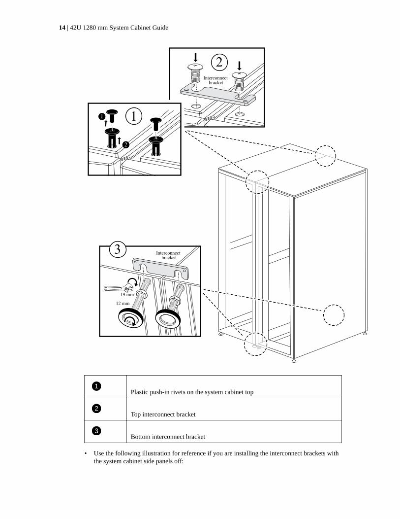
6. Install the interconnect brackets.
• Use the following illustration for reference if you are installing the interconnect brackets withthe system cabinet side panels on, as recommended:
Installing a system cabinet | 13
12 mm
19 mm
Interconnect bracket
Interconnect bracket
1
2
1
2
3
1Plastic push-in rivets on the system cabinet top
2Top interconnect bracket
3Bottom interconnect bracket
• Use the following illustration for reference if you are installing the interconnect brackets withthe system cabinet side panels off:
14 | 42U 1280 mm System Cabinet Guide

7. Repeat the process for any remaining system cabinets.
8. Tighten all interconnect bracket screws.
Installing the bolt-down kitYou can secure the system cabinet to the floor by installing the optional bolt-down kit. Installing thekit prevents the system cabinets from being rolled out of position.
Before you begin
You must supply the appropriate anchor bolt for your floor for each bolt-down bracket.
Steps
1. Mark the area on your floor where the system cabinet will be installed, and then roll the cabinetinto place.
Installing a system cabinet | 15

413 mm1,257 mm
M8x20 mmbolts x2
rear
M8x20 mmbolts x4
front
Secure all 4 brackets to base with
appropriate bolts
(not provided)
1
1
2
1Front and rear bolt-down brackets
2Location of floor anchor point on the bracket
2. Mark the anchoring points where the rear bolt-down brackets will be anchored to the floor, andthen drill the holes for the brackets.
Be sure to use the appropriate bolt sizes and type for your floor.
3. If the bolt-down brackets are too low to align with the mount points on the system cabinet frame,place a spacer bracket over the hole in the floor.
4. Loosely bolt the rear brackets to the floor, and then using the kit bolts, bolt the brackets to thecabinet frame.
5. Mark the anchoring points where the front bolt-down brackets will be anchored to the floor, andthen drill the holes for the brackets.
6. If the bolt-down brackets are too low to align with the mount points on the system cabinet frame,place a spacer bracket over the hole in the floor.
7. Bolt the front brackets to the floor, and then using the kit bolts, bolt the brackets to the cabinetframe.
8. Lower the leveling feet as needed, and then tighten the rear bolt-down brackets to the floor.
Installing additional support railsYour system cabinet has some support rails already installed in it. If you need additional support railsfor your system, you must install them before installing your system components.
About this task
This task applies to all controller and disk shelves except the DS212C and the DE212C disk shelves.Use the instructions in the rail kit flyer applicable to those two disk shelves.
Installing a DE212C or DS212C Shelf in a Two-Post or Four-Post Rack
16 | 42U 1280 mm System Cabinet Guide

Steps
1. Determine how much space your equipment requires.
Calculate the amount of U space (1.75 inches per U) the equipment requires, based on theequipment height, and then determine where the equipment will be installed in the system cabinetbased on available space.
2. Locate where you need to install the support rails, and then install them using the followingillustration for reference:
1
2
5
10x32screw
Use with DS460C only
Use with all othersystem chassis
Repeat the steps for the opposite rail
4Rear view
Front view
10x32screw
3
3. If your equipment mounting flanges extend beyond the screw holes in the support rail, install cagenuts above the support rail, where needed.
Installing a system cabinet | 17
Installing equipment in the system cabinetAfter you have installed any additional support rails into the system cabinet, you can add moresystem components to your prepopulated system cabinet or add your existing system components toan empty system cabinet.
Steps
1. Unlock and open the rear doors of the system cabinet and the front door, if it is not already open.
2. Install your equipment into the system cabinet as described in the installation instructionsaccompanying your equipment.
The storage controllers should be in the middle of the system cabinet. The disk shelves should beabove and below the storage controllers. Any switches should be at the very top of the systemcabinet.
Note: If your equipment mounting flanges extend beyond the screw holes in the support rail,install cage nuts above the support rail where needed to secure the equipment to the cabinetupright.
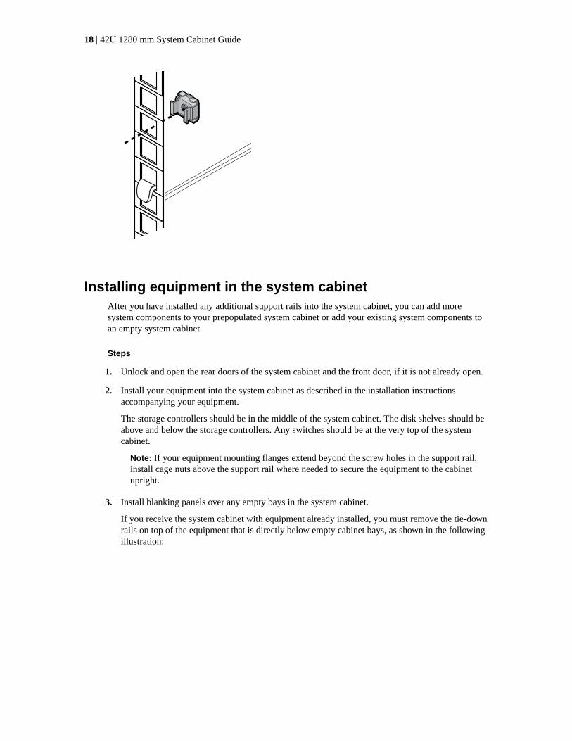
3. Install blanking panels over any empty bays in the system cabinet.
If you receive the system cabinet with equipment already installed, you must remove the tie-downrails on top of the equipment that is directly below empty cabinet bays, as shown in the followingillustration:
18 | 42U 1280 mm System Cabinet Guide

7
Blank shipped on top of unit .
Remove and install.
Rear view
1
5
3
2
6
4
7
7
4. Reinstall the front and rear system cabinet doors.
Powering on the system cabinetYou must connect the system components to the PDUs, route the PDU cables to the AC powersources, connect them to the power sources, and power on the system.
Before you begin
You must have separate power circuits available for each PDU in your system cabinet.
Steps
1. Connect your equipment to the PDUs, making sure that you connect each component's powersupplies to a PDU on opposite sides of the system cabinet.
2. Feed the PDU power cables through an opening in the system cabinet.
Use one of the following openings:
• The top of the system cabinet
• Between the rear door bottom and frame of the system cabinet
• Through the floor opening and under the system cabinet
3. Turn off the power switches or circuit breakers on the PDUs.
Installing a system cabinet | 19

4. Plug each PDU power cable into individual AC power sources that are on separate AC circuits.
5. Turn on the power switches or circuit breakers to the PDUs.
6. Turn on the power to your components, and then boot the system.
7. Close and lock the system cabinet doors.
20 | 42U 1280 mm System Cabinet Guide

Replacing PDUs
You can replace a failed PDU in your system cabinet or replace an existing PDU with a different typeof PDU.
Before you begin
The replacement PDU must be supported by your system cabinet and must provide sufficient powerto the installed equipment.
hwu.netapp.com
Steps
1. Turn off the circuit breakers on the target PDU, and then unplug the old PDU from the AC powersource.
2. Ground yourself to the system cabinet, and then unplug the power cords from each of the systemcomponents and from the PDU.
3. Remove the screws from the PDU frame, bottom screw first.
Note: Ensure that you support the PDU with one hand while you remove the last screw fromthe top of the PDU. This prevents the PDU from dropping or falling toward you after the screwis removed.
4. Remove the old PDU from the system cabinet.
Make sure that you keep track of the mounting screws so that you can reuse them when installingthe replacement PDU.
5. Remove the brackets from the old PDU, and then install them on the back of the replacementPDU.
6. While supporting the replacement PDU, align the slot on the mounting bracket of the PDU withthe top holes of the frame on the inside of the system cabinet, and then secure the PDU to thesystem cabinet frame using the mounting screws from the old PDU.
7. Secure the bottom of the PDU to the system cabinet frame, and then tighten all of the mountingscrews.
8. Verify that all of the power switches or circuit breakers are in the Off position.
If the circuit breakers are not in the Off position, push a small screwdriver or straightened paperclip into the slot to the right of the Off label to trip the circuit breaker and turn off the circuit.
9. Plug the system power cords into the PDU, plugging each component into the PDU outlet directlyacross from the component.
Tip: A best practice is to distribute the total load across the PDU branches, making each branchload as equal as possible.
10. Lock each component power cable plug in place with the cable retainer clip above it by slidingthe curved edge of the cable retainer clip over the plug shoulder.
11. Plug the PDU power cord into the AC power source.
12. Turn on the PDU power switches or PDU circuit breakers.
For PDU circuit breakers, the button is on when it is flush with the PDU frame.
21

Reversing the system cabinet front door
You can change the direction the front door opens by removing the illuminated badge, door, tophinge, and related hardware, and then installing them on the opposite side of the front of the systemcabinet frame.
Before you begin
About this task
You need the following tools and equipment to complete the door reversal for system cabinets withilluminated badges:
• A Phillips screwdriver
• A 5-mm Allen wrench; magnetic Allen wrench is recommended
• Needle-nose pliers
• A step ladder so that you can easily access the Allen bolts in the top hinge
22

Removing the illuminated badgeRemoving the illuminated badge requires that you open the system cabinet front door, unplug thepower cord from the back of the badge, and then remove the badge components from the systemcabinet door.
About this task
Use the following illustration along with the following steps:
Front:
Back:
press
Back:
Front:
2
13
4
Steps
1. Unlock and open the system cabinet front door.
2. Loosen the captive screws on the badge back panel on the inside of the door, and then gently pullthe back panel away from the door mesh.
3. Unplug the power cord from the back panel by pressing the locking clip on the plug, unpluggingthe cord from the socket, and removing the cable from the back panel.
Set the back panel aside.
4. Carefully remove the screws from the back of the badge.
Note: The stems on the thumbscrews are very short. Place your free hand under the screw tocatch the thumbscrew if you drop it.
5. Remove the badge from the front of the door and set it aside.
Reversing the system cabinet front door | 23

Removing the system cabinet doorYou must remove the system cabinet door and side panels to move the illuminated badge andcomponents, and to reverse the door.
Steps
1. Open the system cabinet door if it is not already open.
2. Perform the appropriate action depending on whether your cabinets are connected with theinterconnect kit.
If your system cabinet is... Then...
Not connected to anothersystem cabinet
Go to the next step.
Connected to another systemcabinet with an interconnectkit
Remove all four interconnect kit brackets and set the brackets and screwsin a safe place.
3. Unlock both side panels, disconnect the grounding wires from the side panels, and then removethem and set them aside.
4. Disconnect the grounding wire from the grounding spade located at the top of the door.
5. Unscrew the grounding lug and wire assembly from the system cabinet frame and set it aside.
6. Unscrew the grounding lug assembly from the system cabinet door and set it aside.
7. Lift the top hinge pin until it clears the bottom of the hinge.
8. Gently tip the top of the door away from the system cabinet frame, and then release the hinge pin.
9. Lift the door off the bottom hinge, and set the door aside.
Moving the badge power supply and cablingYou must move the power supply and illuminated badge cabling to the opposite side of the systemcabinet frame before you reverse the door and reinstall the illuminated badge.
Before you begin
You must have removed the system cabinet door and side panels.
About this task
You must move the illuminated badge power supply, power cable, and cabling conduit to the oppositeside of the system cabinet when you reverse the system cabinet door. The assembly is designed sothat the cable to the badge is on the side of the cabinet where the door hinge is installed.
Steps
1. Open the power cable retaining clip, and then disconnect the power cable from the power supply.
2. Remove the power supply housing and power supply, using the illustration for reference:
24 | 42U 1280 mm System Cabinet Guide

2
1
press
a. Lift the retaining pin on the power supply housing, and then remove the housing cover byrotating it downward and lifting it off the rear power supply housing.
Note: The power supply is attached to the power supply housing with a hook and looppatch.
b. Disconnect the power supply from the illuminated badge cable, and then set the power supplyand power supply cover to the side.
c. Remove the screws from the top and bottom of the power supply housing that is attached tothe system cabinet frame, and then remove the power supply housing.
3. Install the power supply and power supply housing on the opposite side of the system cabinet:
a. Locate the two screw holes next to each other on the cabinet frame, and then attach the top ofthe power supply housing to the bottom-most of the two screw holes.
Note: You might need to remove the bottom cable retention strap, if present.
b. Secure the bottom of the power supply housing to the system cabinet frame.
c. Install the power supply cover and power supply by aligning the cover hooks with the powersupply back, pulling the plunger up on the cover, rotating the plunger closed, and thenreleasing the plunger.
Reversing the system cabinet front door | 25

4. Remove the bezel power supply conduit by removing the conduit retaining clips from theretaining clips, and then slide the conduit off the power cable.
Keep the retaining clips and screws for installing the conduit on the opposite side of the cabinet.
5. Move the badge power cable to the other side of the cabinet:
26 | 42U 1280 mm System Cabinet Guide

180o1
a. Rotate the rubber cable retainer on the cabinet upright 180° to the right, remove it from thesystem cabinet frame, and then gently pull the cable out of the system cabinet.
b. Move the cable to the other side of the cabinet, and then thread it completely through the holenear the top of the cabinet upright.
c. Align the rubber cable retainer with the hole in the frame, push it in as far as it will go, andthen rotate the cable retainer 180° to the left to secure it.
d. Run the cable along the cabinet frame to the back of the cabinet.
6. Reinstall the cable conduit:
a. Slide the conduit over the PDU power cable and route the conduit along the system cabinetframe to the PDU.
b. Install the conduit retaining clips from the other side of the cabinet over the conduit to secureit to the cabinet frame.
7. Plug the badge cable back into the power supply, but do not reconnect the power supply to thepower source.
Reversing the door hinge and lock catchWhen reversing the system cabinet door, you must move the system cabinet door hinge and lockcatch to the opposite front-side system cabinet upright.
Before you begin
You need the following tools:
• Phillips screwdriver
Reversing the system cabinet front door | 27

• 5 mm Allen wrench; magnetic Allen wrench is recommended
• Needle-nose pliers
• Step ladder so that you can easily access the Allen screws in the top hinge
Steps
1. Remove the screws securing the top hinge from the system cabinet frame, and set the screws andhinge aside.
Attention: Be careful when removing the Allen screws to avoid dropping them into the cabinetframe. Spare Allen screws are provided in the spares kit that shipped with your system cabinet.
2. Remove the screws securing the bottom hinge from the system cabinet frame, and set the screwsand hinge aside.
4
5
1
2
3
1Door grounding screw with grounding wire spade
2Grounding wire
3Frame grounding wire lug
4Top front door hinge with hinge pin held by retaining clip
5Lock catch
3. Reverse the hinge pin from the top hinge:
a. Lift the hinge pin and expose the retaining clip on the hinge pin shaft.
28 | 42U 1280 mm System Cabinet Guide

b. Using the needle-nose pliers, gently remove the retaining clip from the hinge pin shaft and setit aside.
c. Slide the hinge pin and spring out of the hinge body.
d. Rotate the hinge so that the thread holes are facing the opposite side of the hinge, and theninstall the hinge pin and spring back into the hinge.
e. Install the hinge retaining clip onto the hinge pin.
Make sure that you push the retaining clip completely onto the hinge pin.
4. Reinstall the hinges:
a. Insert the top Allen screw through the system cabinet upright, aligning it with the top threadedhole on the top hinge, and then partially tighten the Allen screw.
Do not completely tighten the screw until after the second Allen screw is installed.
b. Insert the bottom Allen screw through the system cabinet upright, aligning it with the bottomthreaded hole on the top hinge, and then partially tighten the Allen screw.
c. Tighten the top and bottom Allen screws.
d. Repeat these steps for the bottom hinge.
5. Remove the screws from the lock catch, and then move the lock catch to the opposite front-sidesystem cabinet upright.
6. Rotate the catch 180 degrees, and then secure it to the system cabinet upright.
Reinstalling the door and illuminated badgeAfter you move the power supply and components to the other side of the system cabinet and movedthe hinges and lock catch, you must reinstall the system cabinet door and the illuminated badge, andthen reconnect the badge to the power source.
Reinstalling the system cabinet door
After you reverse the door hinge and door catch, you must reinstall the grounding wire and lugassembly and wire, and the system cabinet front door prior to reinstalling the illuminated badge.
Steps
1. Rotate the door 180 degrees.
2. Align the bottom of the door with the bottom hinge post, and then seat the door bottom on thehinge post.
3. Lift the top hinge pin so that it clears the hinge housing.
4. Tip the top of the door into the hinge housing so that the hinge pin and door hinge are aligned,and then release the hinge pin.
Make sure that the hinge pin is seated completely through the door hinge and the bottom of thedoor hinge housing.
5. Reattach the grounding lug and wire assembly to the system cabinet frame on the same side of thenewly reversed front door and reinstall the grounding lug with spade on the top of the systemcabinet door.
6. Reattach the grounding wire to the spade on the grounding lug assembly on the system cabinetdoor.
Reversing the system cabinet front door | 29
7. Reinstall either the side panels or the interconnect brackets, as applicable:
• If your system cabinet is not connected to another system cabinet, reinstall the side panels.
• If your system cabinet is connected to another system cabinet with an interconnect kit,reinstall the interconnect brackets.
Reinstalling the illuminated badge
After the system cabinet door is installed, you need to install the illuminated badge to complete thedoor reversal process, and then close and lock the front door.
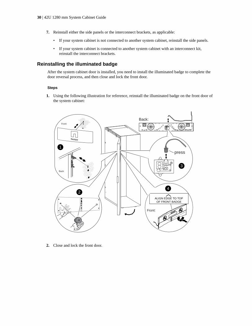
Steps
1. Using the following illustration for reference, reinstall the illuminated badge on the front door ofthe system cabinet:
Front:
Back:
Back:
Front:
ALIGN EDGE TO TOPOF FRONT BADGE
1
24
press
3
2. Close and lock the front door.
30 | 42U 1280 mm System Cabinet Guide

Copyright information
Copyright © 2018 NetApp, Inc. All rights reserved. Printed in the U.S.
No part of this document covered by copyright may be reproduced in any form or by any means—graphic, electronic, or mechanical, including photocopying, recording, taping, or storage in anelectronic retrieval system—without prior written permission of the copyright owner.
Software derived from copyrighted NetApp material is subject to the following license anddisclaimer:
THIS SOFTWARE IS PROVIDED BY NETAPP "AS IS" AND WITHOUT ANY EXPRESS ORIMPLIED WARRANTIES, INCLUDING, BUT NOT LIMITED TO, THE IMPLIEDWARRANTIES OF MERCHANTABILITY AND FITNESS FOR A PARTICULAR PURPOSE,WHICH ARE HEREBY DISCLAIMED. IN NO EVENT SHALL NETAPP BE LIABLE FOR ANYDIRECT, INDIRECT, INCIDENTAL, SPECIAL, EXEMPLARY, OR CONSEQUENTIALDAMAGES (INCLUDING, BUT NOT LIMITED TO, PROCUREMENT OF SUBSTITUTEGOODS OR SERVICES; LOSS OF USE, DATA, OR PROFITS; OR BUSINESS INTERRUPTION)HOWEVER CAUSED AND ON ANY THEORY OF LIABILITY, WHETHER IN CONTRACT,STRICT LIABILITY, OR TORT (INCLUDING NEGLIGENCE OR OTHERWISE) ARISING INANY WAY OUT OF THE USE OF THIS SOFTWARE, EVEN IF ADVISED OF THEPOSSIBILITY OF SUCH DAMAGE.
NetApp reserves the right to change any products described herein at any time, and without notice.NetApp assumes no responsibility or liability arising from the use of products described herein,except as expressly agreed to in writing by NetApp. The use or purchase of this product does notconvey a license under any patent rights, trademark rights, or any other intellectual property rights ofNetApp.
The product described in this manual may be protected by one or more U.S. patents, foreign patents,or pending applications.
Data contained herein pertains to a commercial item (as defined in FAR 2.101) and is proprietary toNetApp, Inc. The U.S. Government has a non-exclusive, non-transferrable, non-sublicensable,worldwide, limited irrevocable license to use the Data only in connection with and in support of theU.S. Government contract under which the Data was delivered. Except as provided herein, the Datamay not be used, disclosed, reproduced, modified, performed, or displayed without the prior writtenapproval of NetApp, Inc. United States Government license rights for the Department of Defense arelimited to those rights identified in DFARS clause 252.227-7015(b).
31

Trademark information
NETAPP, the NETAPP logo, and the marks listed on the NetApp Trademarks page are trademarks ofNetApp, Inc. Other company and product names may be trademarks of their respective owners.
http://www.netapp.com/us/legal/netapptmlist.aspx
32

How to send comments about documentation andreceive update notifications
You can help us to improve the quality of our documentation by sending us your feedback. You canreceive automatic notification when production-level (GA/FCS) documentation is initially released orimportant changes are made to existing production-level documents.
If you have suggestions for improving this document, send us your comments by email.
To help us direct your comments to the correct division, include in the subject line the product name,version, and operating system.
If you want to be notified automatically when production-level documentation is released orimportant changes are made to existing production-level documents, follow Twitter account@NetAppDoc.
You can also contact us in the following ways:
• NetApp, Inc., 1395 Crossman Ave., Sunnyvale, CA 94089 U.S.
• Telephone: +1 (408) 822-6000
• Fax: +1 (408) 822-4501
• Support telephone: +1 (888) 463-8277
33

Index
A
adding system componentsto prepopulated system cabinets 18
B
bolt-down kitssecuring system cabinet to the floor 15
C
cabinetsfeatures for setting up and cabling 4reversing door hinge and lock catch on system 27
commentshow to send feedback about documentation 33
componentssystem cabinet setup and cabling 4
D
dimensionssystem cabinet 6
documentationhow to receive automatic notification of changes to33how to send feedback about 33
doorsreversing system cabinet 27
E
empty system cabinetsinstalling system components 18
equipmentrequired for installing 6
F
featuressystem cabinet setup and cabling 4
feedbackhow to send comments about documentation 33
front doorsreversing 22
H
hingesreversing system cabinet door 27
I
illuminated badgeinstalling 29removing 23
illuminated badge removal 23information
how to send feedback about improvingdocumentation 33
installationrequired tools for 6
installingadditional support rails 16equipment in an empty system cabinet 18illuminated badge 29introduction to 10
interconnect kitsconnecting system cabinets together using 10
K
kitsfeatures 4
L
lock catchreversing system cabinet door 27
M
movingsystem cabinet power supply illuminated badgepower supply and cables 24
O
optional kitsdescription of system cabinet 4
P
PDU internal wiringsupported types of 8
PDUsreplacing 21supported types of 8
power suppliesmoving system cabinet illuminated badge 24
powering onsystem cabinets 19
R
reinstallingthe system cabinet door 29
removingsystem cabinet door 24the illuminated badge 23
replacingPDUs 21
reversing
34 | 42U 1280 mm System Cabinet Guide

system cabinet door hinge and lock catch 27the door 22
S
setupintroduction to installing 10
space requirementssystem cabinet 6
suggestionshow to send feedback about documentation 33
support railsinstalling additional 16
supported PDUstypes of 8
system cabinet doorremoving 24
system cabinet doorsreinstalling 29
system cabinetsconnecting with the interconnect kit 10dimensions and space requirements 6
features for setting up and cabling 4installing bolt-down kit to secure 15introduction to preparing to install 4powering on 19reversing door hinge and lock catch 27unpacking 9
system componentsadding to prepopulated system cabinets 18
T
toolsrequired for installing 6
Twitterhow to receive automatic notification ofdocumentation changes 33
U
unpackingsystem cabinets 9
Index | 35