System Aspects of Smart Antennas Technologyipd481/Papers varios/presentacion.pdf · System Aspects...
71
System Aspects of Smart Antennas Technology Helsinki University of Technology Communications Laboratory
Transcript of System Aspects of Smart Antennas Technologyipd481/Papers varios/presentacion.pdf · System Aspects...

System Aspects of SmartAntennas Technology
Helsinki University of TechnologyCommunications Laboratory

5/6/99 2
Content1. Introduction2. Main components of wireless network influenced by SA tech.3. Radio Interface Receiver Structure and Algorithms Air interface compatibility with SA Integration SA receiver into cell environments4. Network Planning HSR, SFIR, SDMA , SFIR-SDMA concepts CDMA network planning with SA, 3-G /UTRA with SA Network upgrade with SA Network simulation with SA5. Network Control with SA Layer 1, 2 ,3 Handover, Initial access, Resource management with SA, packet transmission with SA6. Conclusion: research problems7. Existing SA commercial and test systems their performance

"Spatial Processing remains as the most promising,if not the last frontier, in the evolution of multiple
access systems"
Andrew Viterbi

5/6/99 4
Existing SA commercial productsand experimental systems
- MetaWave (Switched-Beam SA)
- ArrayComm (PHS,WLL, )- Raytheon (SW based )
- Ericsson (System Level Testbed- GSM/DCS)- DoCoMo (Testbed with 3 BS - W-CDMA)
- TSUNAMI - SUNBEAM
- Lucent ...

5/6/99 5
1. IntelliWave Wireless Local Loop System

5/6/99 6
1. Main Advantages of SmartAntennas Technology
- CCI cancellation at the up and down links -> - CCI cancellation at the up and down links -> capacitycapacity
- SNR improvement due to antenna gain -> - SNR improvement due to antenna gain -> coveragecoverage
- Effects of multi-path mitigation - Effects of multi-path mitigation -> high -> high QoSQoS, bit rate, bit rate

5/6/99 7
1. Main Advantages of SmartAntennas Technology for:
Operator ->Operator -> Network capacity, coverage, Network capacity, coverage, filling “dead spots”, less amount of BS,filling “dead spots”, less amount of BS,QoSQoS, new services.., new services..
OEM ->OEM -> New more advanced BSS equipment, New more advanced BSS equipment,more flexible radio network control... more flexible radio network control...
User ->User -> Higher Higher QoSQoS, more reliable, secure, more reliable, secure communication, longer battery life... communication, longer battery life...

5/6/99 8
2. Impact of Spatial Processing Technology onCellular Mobile Communications.
Network Planning-
- WCDMA air interface- packet/ circuit- multi-rate services- user dedicated pilotsat the up and downlinks
Smart Ant. Tech.
4G
3G
2.5G
2G
3G -
2G- GSMsome limitationsby standard forspatial proc. tech.
2.5G-GPRS
1G
Radio Interface
-Receiverstructure-Tx, Rx alg.
Air Interface
ICtech.
SWradio
Packet transfer
WirelessATM
relaying
SA at MS
RadioNetworkManagement
4G-High-speed WLAN < 60GHz
1G- analog systems
mobile localization
Reconfigurable Mobile Network

5/6/99 9
2. Impact of Spatial Processing Technology on Cellular Mobile Communications.
Smart Ant. Tech.
Network Planning- Capacity Planning- Coverage Planning- Interference Planning- Joint fixed and radio networkoptimization, planning- System upgrade, economical issues
Network control- Resource manag. (DCA)- call control
Radio Interface
Receiver structure,Tx, Rx algorithms
- Antennas- Spatial proc.- Time dom. processing- Channel coding- Detection- Diversity
Air Interface- Multiple access- Duplexing- Modulation- Framing- Availability of pilots
DSP tech.
SWRadio
Radio NetworkManagement
Link level control
- Power Control - Quality Control- Tracking
Cell control- admission control- broadcast ch. control- handover control- macro-diversity control
Service -> MS location

5/6/99 10
2. System Aspects of Spatial Processing TechnologyMobile Communications. Main Interactions.
Expected cells load variationsLayers structure…...
NetworkPlanning:
Propagation Maps
- offered traffic spatial distribution, services. -mobility
=Network Infrastructure (BS position, ant. parameters,fixed network. topology)
UMTS environments
Radio channel,Interference environment,mobility,services
Receiver,antennas parameters
Radio Interface
-Receiverstructure-Tx, Rx alg.
Air Interface DSP tech.
Smart Ant. Tech.
3G
Protocols,dynamic
System parametersrelated to controlfunctions
Radio Network Management
C U

5/6/99 11
3. Spatial processing techniques
- Macro-diversity(omni and directional ant.)- Sectorisation- Switched-beam system- Phased arrays,Adaptive Antennas- Joint Space - Time,MU ST processing,Rec.- Trx .- Spatial-temp coding- Multiple antennas at MS and BS

5/6/99 12
3.Types of Smart Antenna Receivers- Switched beam, adaptive algorithms.. - Side reference information available (Spat Ref. , Ref. Signal, signal structure and their combinations) for spatial processing
- Narrowband , broaband (CDMA)
- Optimization method (if any) (max ML, min MSE, MV, MAP)
- Processing domain -> Space, Space-Time, …
- Amount and type of channel knowledge available
- Combination of space/space-time processing with other technologies (diversity, interference cancellation, channel coding, space-time coding …)
- SA at the MS

5/6/99 13
SA receivers structures
Demod. Det.RF IF
W
W
W
W
W
W
W
W
W
BF BF Comb.
SideInformation
PsignalCIR
SINR Data, BER
BBSpat. Sign.
Time Ref.Time Ref.post det
Ref.SS

5/6/99 14
Switched-beam and adaptive antenna
Acquisition initialweights W generation(omni directional , scanning, obtaining reference signal)
Beam-forming W
θ
Error (t)
P( )->
or ε
θ
AoA trackingAdaptivealgorithm
Tracking modeAcquisition mode
Reference
Beam-forming
W
Reference
P( )->
Beam(s) selection
Set of fixed beams
Acquisition mode
Acquisition(omni directional ,scanning-switching ,…..)

5/6/99 15
3. References for beamforming or/andoptimum combining
- Spatial Reference based BF,Direction of arrival BF
- Reference signal based/time reference BF and/or optimum combining
- Signal Structure (temporal /spectral) based BF/ property restored BF
Optimal

5/6/99 16
3. Direction of Arrival Based Beamformers
- require angle of arrival (AOA)estimation
- estimates output power at theoutputor eigen-decomposition ofcorrelation matrix
- sensitive to AoA estimationerrors,calibration problem
- problem with coherent multipath
- As/A should be low
- FDD applications
Array
ProcessorθArray Output

5/6/99 17
3. Reference Signal (Time) Based Beamformersor/and optimal combiner (TRB)
- requires reference signal or the replicacorrelated with desired signal- based on Wiener solution (MSE)- reference signal multiplexed with des.signal or reconstructed signal obtainedfrom detected symbols (det. and BF dep.attractive for tracking)- better for varying radio channel- diversity- more processing extensive methods- receiver is simpler at expense ofspectral efficiency- synchronization problem- Ds/T should be low- TDD applications
Beamformer
Σ
W1
W2
Wn
+
Arrayoutput
Error- +
Ref.
y(t)
X1(t)
X2(t)
Xn(t)
Controlalgorithm
Signal processor
1
2
N
Adaptive processor

5/6/99 18
3. Signal Structure Based Beamforming
- Do not require reference signal - - Do not require reference signal - more spectral efficientmore spectral efficient
- useful method tracking between references- useful method tracking between references
- convergence properties ?- convergence properties ?
- methods based on partial information are- methods based on partial information areusually non-linearusually non-linear
- performance from robustness point of vie- performance from robustness point of vie
are similar to reference signal based methodsare similar to reference signal based methods
BF(W)
CMA

5/6/99 19
Beamforming Methods
Data independent beamforming (CBF,..)
Optimum BF
- Based on cost function maximization/minimization (max SINR,…)
- Based on Statistical Estimation ML (Likelihood function)MSE (Reference ) - Adaptive algorithms (LS…., MAP,…)
(GSLC,…)

5/6/99 20
3. Achievable Improvements with SA
- Improvement in signal to noise ratio due to beamformingarray gain. Improve coverage.
- Mitigation of multipath effects. Reduce ISI.
- Enhance spatial diversity.
- Interference Cancellation. In Tx and Rx. Capacity.
These goals may be conflicting. Need blancing to achievesynergy with propagation enviroment, offered traffic,infrastructure.

5/6/99 21
Trade-offs between achievable improvements with SA SNR CCI Div. ISI Time Div Doppler
Spa
ce D
om. P
roc .
S-T
Pro
cess
ing
Sign
al
Dom
.
Data Indep. BF
Optimal BF
Space ref.
Ref. Signal
SS based BF
Combining
Opt.Comb.
Based on ref.
signal
Blind SS
Optimization

5/6/99 22
SNR CCI Div. ISI Time Div Doppler
Spa
ce D
om. P
roc .
S-T
Pro
cess
ing
Sign
al
Dom
.
Data Indep. BF
Optimal BF
Space ref.
Ref. Signal
SS based BF
Combining
Opt.Comb.
Based on ref.
signal
Blind SS
Max. SNR
BSBS MSMS
Beamforming
Combining

5/6/99 23
Spa
ce D
om. P
roc .
S-T
Pro
cess
ing
SNR CCI Div. ISI Time Div DopplerSi
gnal
D
om.
Data Indep. BF
Optimal BF
Space ref.
Ref. Signal
SS based BF
Combining
Opt.Comb.
Based on ref.
signal
Blind SS
Combining
3. CCI cancellation
BSBS
MS 1MS 1
Interfering Interfering MS 2MS 2
Beamforming

5/6/99 24
Spa
ce D
om. P
roc .
S-T
Pro
cess
ing
SNR CCI Div. ISI Time Div DopplerSi
gnal
D
om.
Data Indep. BF
Optimal BF
Space ref.
Ref. Signal
SS based BF
Combining
Opt.Comb.
Based on ref.
signal
Blind SS
Combining
3. Diversity
Multi-pathMulti-path
BSBS
MS MS
Beamforming
Space Div.
Ang. Div.

5/6/99 25
Spa
ce D
om. P
roc .
S-T
Pro
cess
ing
SNR CCI Div. ISI Time Div DopplerSi
gnal
D
om.
Data Indep. BF
Optimal BF
Space ref.
Ref. Signal
SS based BF
Combining
Opt.Comb.
Based on ref.
signal
Blind SS
3. ISI cancellation
MultipathMultipath
BSBS
Path with ISIPath with ISI
Delayed Signals
Combining
Beamforming

5/6/99 26
Spa
ce D
om. P
roc .
S-T
Pro
cess
ing
SNR CCI Div. ISI Time Div DopplerSi
gnal
D
om.
Data Indep. BF
Optimal BF
Space ref.
Ref. Signal
SS based BF
Combining
Opt.Comb.
Based on ref.
signal
Blind SS
3. Optimal Algorithms
BSBS
MS 1MS 1
Multi-pathMulti-path
Interfering Interfering MS 2MS 2
Path with ISI,Path with ISI,uncorrelated uncorrelated pathspaths
Beamforming
Delayed Signals
Combining

5/6/99 27
SNR CCI Div. ISI
Spa
ce D
om. P
roc .
Sign
al
Dom
.
Optimum
Data Indep. BF
Optimal BFSpace ref.
Ref. Signal
SS based BF
Combining
Opt.Comb.
1/M (M-1) ~M ang. div (M-1)
Optimum
(M-1) M spat div. (M-1)/2 interferes gain del. symb.or M-1 del. signals with any. del
- amount of SA elements (M) can be considered as resource
- M define also “spatial selectivity” of SA

5/6/99 28
3. Optimal S-T Algorithms S
pace
Dom
. Pro
c . S
-TP
roce
ssin
g SNR CCI Div. ISI Time Div Doppler
Sign
al
Dom
.
Data Indep. BF
Optimal BF
Space ref.
Ref. Signal
SS based BF
Combining
Opt.Comb.
Based on ref.
signal
Blind SS
Delayed Signals
Time

5/6/99 29
3. S-T Processing- Space Processing:- Efficient CCI mitigation - Space Diversity- ISI mitigation depends on As of multipath and amount of SA elementsand cannot be very efficient
- Time Only ProcessingVery limited against CCITime diversity, ISI mitigation
- ST Processing- Simultaneous operations in Time and Space- ST-ML and ST-MMSEJoint ST- Channel and Data Estimation(ST- JCDE) - SS blind methods..- MU-ST Processing - Joint Rec. Tr. ST-Processing
Demod
Demod
ST-MLSE
ST-MMSE
ST-CMA
VectorVA
W
W
Sk
Sk
Sk
Channel
Training
yk
yk
f(y)
Σ-
+
5/6/99 30
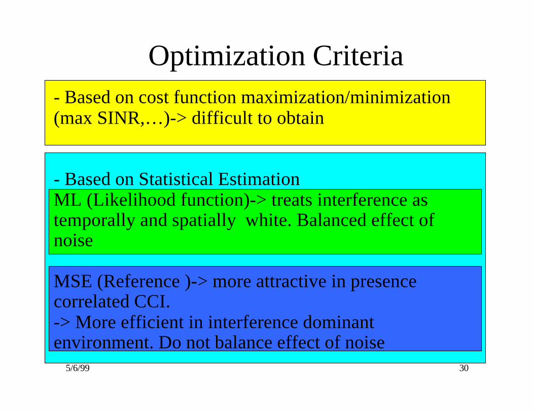
Optimization Criteria- Based on cost function maximization/minimization(max SINR,…)-> difficult to obtain
- Based on Statistical EstimationML (Likelihood function)-> treats interference astemporally and spatially white. Balanced effect ofnoise
MSE (Reference )-> more attractive in presencecorrelated CCI.-> More efficient in interference dominantenvironment. Do not balance effect of noise

5/6/99 31
SNR CCI Diversity ISI Time Div.
S
T
S
T
S
patia
l
B
eam
form
ing
BF
dive
rsity
r
ecei
ver
d
iver
sity
Opt
imal
Dat
a
i
ndep
ende
nt
Convent. BF Matched BF Null BF MU BF
Space Ref. BFML
Ref. Signal Bfor/and OC
sel . div
MRC
Non Coh.
Wiener Filt.
MLSE
MMSE
STF/MLSR
1/M (M-1) K , M (M-1)/2 , M-1
- conflicting parameters
- joint optimum
- choice between two opt.
Diversity
No path diversity since ISI regardedas interference
3. SA Receiver integration into cell environment
Macrocell
Microcell
Complex
More Simple
Receiver. complexityTracking

3.TDMA Rx Structures (Ch. Knowledge <->Optimality)
After A. Paulraj
S-DIV CCI ISI T-DIV
X X X X
X X X X
X X X X
X X X X
X
Decreasing Channel Knowledge
MU-MLSE
ST-MMSE-MLSE
S-MMSE-MLSE
MMSE
ANT-HOP
H1 H2
H1 RS-T
H1 RS
H1 θ
Nil

3. CDMA Rx Structures (Ch. Knowledge <-> Optimality)
After A. Paulraj
S-DIV T-DIV MUI
X X X
X X X
X X X
X X
X
Decreasing Channel Knowledge
ST-MU
ST-MMSE
ST-RAKE
BF-RAKE
ANT-HOP
H1 H2
H1 RS-T
H1 RS
H1 θ
Nil

5/6/99 34
3. SA receivers types and algorithms
Space reference BFOpt. SINR, ML, MSE
Reference signalbased BF and/or
OC (MSE)
Signal Structure based BF(SE,..)
AoA estimation
Signal properties (t,f)
Referencesignal,..
Tracking in time
Reference signalbased ch. est.(ML, MSE)
Signal structure ch. est (MSE,..)
Optim. Alg.max. SINR,ML,MSE,...
Spat
ial D
omai
n Pr
oc.
S-T
pro
cess
ing
Tracking ofchannel variation
Referencesignal,..
Signal properties (t,f)
Sign
al d
omai
n

5/6/99 35
SpaceDomainProcessing
Time DomainProcessing
SSBFRef.signal TRB DOB
Data indepen-dent BF
Statistically optimum BF
AoA estimation
CM Adaptive GSC CBF LMS, RLS MVDR
Otimizationcriteria- max.SINR- MSE and MV- ML
Non-blindRef. sign
BlindCM, FA
ST blind algorithms CM, OS
ST - non blind algorithmsMMSEMLSE
3. Space Domain Only and Space-Time SA Algorithms

5/6/99 36
3. Wideband Beamforming Broadband beamforming (TDL filter):
w11 w12 w1J
wL1 wL2 wLJ
Σ
Σ
Σ
Output
w i1
wi2w iJ
w1 w2 wJ
TT T
TTT
x t1 ( )
x tL ( )
x tj ( )
T1( )θ
TL( )θ
Ti ( )θ
FIR filter
Optimum filters with specify rejection response
Weighted Chebyshev method
Davis beamformer, which adapts one filter at a time ...................................................

5/6/99 37
3. Wideband SA receivers.BF + Space-Time RAKE (single user approach)
WidebandBeamformer (BF):
switched-beam
* AOA (Eigen, multi-targ.BF)* Eigenfilter approach
- Ref. signal-.> MSE- CMA ?- code-filteringexploit spatial and temporalsiganal structure + Eigen F.
1 or 2D RAKEreceiver

5/6/99 38
3. Wideband SA receivers .Multi-user MLSE.
Bank of the matched filters
Multi-user VA
- computational complexity linear to the number of users- same degree of the near-far resistance and error rate performanceas optimum MU receiver- require knowledge of the all users channels - optmal in Gaussian noise only

5/6/99 39
- In non-multiuser case users are seen as interference to eachother and there are many weaker CCI in the uplink.
- Multipath gives rise to the MAI due to the losses of codesorthogonality.
- code can seen as “free” reference signal
- ISI compensation has less importance in CDMA thaninterchip interference (ICI). But for very high bit rate ISIcancellation may be required.
- Channel estimations can be based on spreading codes and itpresumes introduction of novel techniques
- Wideband beamforming realization and methods of AOAestimation are different from narrowband
3. Wideband SA receivers

5/6/99 40
3. Wideband SA receivers - For low SNR sophisticated spatial-based blind methods are not efficientand it was the reason of more extensive research in the area of switched-beam solutions for system with IS-95 air interface.
- User dedicated pilots at the up- and down-links of the UMTS airinterface give additional advantage for SA technology especially in highlyloaded cells (MMSE).
- In CDMA the forward link channel estimation problem is simpler than inTDMA because it is possible to decouple the channel mapping for eachpath and deal with lower angle spread.
- In CDMA SA receiver is less sensitive to channel estimation errors butbeam pattern optimization can be is more complex.
- In multi-bit rate CDMA SA receiver can successfully cancelinterference coming from the limited number of high bit rate users thusconsiderably increasing system capacity .

5/6/99 41
3. Impact of an air interface parameters on STreceiver structure and algorithms
Mappingcontrol andtrafficchannelsintophysical channel(s)
PhysicalChannelDefinition,Multi-plexing
FrameStructure
DuplexingTechnology
RF- Channelparameters
MultipleAccess
Technology ChannelCoding
SourceCoding
Interworking
ModulationTechnology
TDMAFDMACDMA
FDDTDD
Availabilityof the trainingsequencesFrame length
Packetstructureand length
Modulation typeCM...Digital Modulation (FiniteAlphabet)LinearitySymbol or chip interval - T
Combinationwith Space ProcessingBandwidth - B
Carrierfrequency fo
Antennas elements geometry,numbers of elements - M. Radio Transmission Technologies
Up<->Downlinks
Up<->Downlinks Wideband rec,
BF, AoA estWideband rec, BF, AoA est
Blind methodsSS BF, S-T
Blind methodsSS BF, S-T
Dopplerspread
Ref. Signal based BF, S-T
Ref. Signal based BF, S-T
MS

5/6/99 42
Combination SA receiver withother signal processing tech.
- Diversity (polarization, space )
- ST coding
- RAKE receiver
- MU detection
- Decoupled time domain processing

5/6/99 43Power Control
3. SA Receiver integration Algorithm (Up-Link)
Radio Channel
- Spread:Time,Doppler,Angle
- Fading -
Interference - Power level- Spatial, temporaldistribution,- bandwidth - correlationproperties
=
BER,delay/service
Requirements forST receiver:- CCI mitigation- Diversity- ISI reduction- SNR
Dynamic parameters- algorithm convergencetime,- tracking
Implementation- SW, HW complexity
+
Air interface type, system parameters
Users
MS mobility/service type
Noise
Offeredtrafficspatial,temporal,spectraldistribution
Targetrequirements/for service
SIR

5/6/99 44After A.Paulraj
3. Macrocell and Microcell Channel Response
Microcell Macrocell
Delay (microsec)0 1 0 20
θ
θθ
-1800
1800
θ
1800
Delay (microsec)
Remotescatters
Scatterslocal toBS
Scatterslocal toMS

5/6/99 45
3. Relations between spreads and relativequantities of interests for different types of cells.
Location of scatters
at MS at BS Remote
Dopplerspreadfd = fo(v/c)DelayspreadDsAngle spreadAs
Spread Type
Criticalsystemparameter
MS motion
static
ArrayResolution
A=1/MAs/A
B
TMicrocell
Macrocell
Ds/T
fd/B

5/6/99 46
TDMACell type Spatial domain-only processing Space - Time ProcessingMicrocellHigh angular spread (As),High traffic - CCIdominant,low user mobilitylow delay spread
TRB (Reference signal based)Downlink spatial selectivetransmission to improve capacity.Downlink BF in TDD can be basedon up-link BF.
ST-MMSEST-MLSE - if ISI more important problemthan CCI
Macrocelllow angular spread,low traffic,high user mobility
DOB. Performance depends on theratio As/M.For ISI limited transmission somedegree of freedom can be spent forISI cancellation at expense of timediversity or CCI cancellation.
ST-MLSEST-MMSE for users with high mobilityMixed solution STF/MLSE
CDMAMicrocell Eigenfilter approach
SSBF code-filteringTRB based on training signal
2D RAKE based on MMSE and RAKE
Macrocell Some superresolution algorithmscan be used for AoA estimationTRB based on training signalSwitched beam SA
2D RAKE based on MMSE and RAKE
Table 1. Compatibility of SA receivers structures and algorithms.
3.Compatibility of SA receivers structures and algorithms

5/6/99 47
4. Network Planning with SA
1. Concepts of HSR, SFIR, SDMA.. in TDMA networks
2. CDMA network planning with SA (near-far problemmitigation).
3. Feasibility of sectorization and SA (3-4 sectors with SA based on ULA)
4. Networks upgrade with SA (different areas, strategies)
5. Simulation tools

5/6/99 48
4. Three Stages of Introduction AdaptiveAntenna Technology in Cell Planning
Process
1. High Sensitivity Reception (HSR)
2. Spatial Filtering for Interference Reduction (SFIR)
3. Space Division Multiple Access (SDMA)
4. SFIR+SDMA ?

5/6/99 49
4. HSR concept
- SA at the up-link only
- Gain approx. 10logM
- with 8 elements reduction of BS by factor of 0.3 by factorof 0.5 with diversity -
BSBS MSMS
Multi-pathMulti-path
BSBSMS MS
5/6/99 50
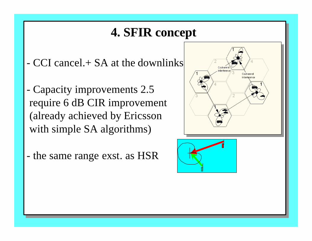
- CCI cancel.+ SA at the downlinks
- Capacity improvements 2.5 require 6 dB CIR improvement (already achieved by Ericsson with simple SA algorithms)
- the same range exst. as HSR
4. SFIR concept

5/6/99 51
- it was found reasonable to combine in GSM SFIR withrandom slow FH to benefit from interference and frequency div.
-reuse factor 1/3 seems resonable1/1 possible but to complex sincedynamic RR manag. based on CCImeasurements is required
- frequency re-planning , but network control (RR) less affected
4. SFIR concept

5/6/99 52
4. SDMA concept- Expected up to 8 times capacity improvements-
- power classes concept (dyn./ stat.)
- with ref. signal BF MS can be separated even when they have the same angular position to BS!
- network planning (frequency) is simpler, but larger cell size can require new planning, smooth migration into existing network
- more network management upgrade required
BSBS
PCH 1 PCH 1
PCH 1PCH 1

5/6/99 53
4. SFIR+SDMA concept
- In theory it is possible to combine SFIR and SDMAconcepts
- Intercell reuse distance (1/n) and intracell reusedistance of co-channels will increase
- Complexity is very high to be implemented in the near future

5/6/99 54
4. CDMA network planning with SA- Reuse factor 1, only “SFIR” concept is applicable
- In multi- layer ( single carrier ) CDMA network may (?)exist since SA can reduce near-far effect
- Range will increase - Capacity will increase since less interferenceat the receiver
- SA can be very effective in interference suppressionwhich is coming from high bit rate users (UTRA)

5/6/99 55
4. Impact of SA on Network Planning
Capacity Planning
Coverage Planning
Frequency/interferencePlanning
Network Upgrade
larger capacity
extended rangeUp/Down L balance
BF and non BFchannels reuseSFIR require re-planning
smooth migrationother techniques

5/6/99 56
4. The Main Direction in IncreasingCapacity of future Cellular Systems
CellPlanning
SDMACell RepeatPattern
- Codec rate- More spectrally efficient modulation- Cells spliting

5/6/99 57
4. Evolutional Path for System Upgrades of aMobile Communication Systems
rural areas“low end”
urban areas“higth end”
urban areassectorised cell
codec rate reduction
SDMA
spectrum upgrade
cell splitting
codec rate reduction codec rate reduction
spectrum upgrade spectrum upgrade
sectorisation SDMA
SDMA cell splitting
cell splitting

5/6/99 58
4. Spatial Distribution of Signal Power with SA
SA

5/6/99 59
4. Radio Network Simulator “NetSim” * NetSim - simulation tool for study Planning Methods and Control Algorithms (power , admission control, handover)for Cellular Radio Networks with Adaptive Antennas .
* NetSim provides detail information about capacity, coverageand control algorithms performance of cellular system.
* NetSim well fit to the existing gap between signal level simulators(COSSAP) and higher level network simulators (OPNET) and can used in combination with them.
* NetSim can be easily updated for different air interface standards and propagation models.

5/6/99 60
4. “NetSim” structure Current version Version under development
Pedestrians on Models domestic users predefined route and car passengers
Control and traffic Multi-services model channels model packet and circuit Voice service switchedwith VAD
Deterministic -Deterministic 3D raytracing model raytracing models - Model based on measurements - Statistical model
Conventional, 2D-RAKE,optimal more complexbeamformers SA models.. downlink model
SIR base Joint BS assignment,distributed power control andpower control beamforming
Soft/hard HO, Multi-carrier network optimum simulation combining at the uplink
Visualization tools
Users Model: locations, velocities
Teletraffic Model/ Services
Propagation data processing
Smart Antennas Models
RAKE Receiver model/Interf.Model
Power Control Model
Admission Control Model
Quality Monitoring
HO, macro-diversity Control Model
Offered traffic/servicespatial distribution
SIR
System performance related data
Referencescenario
ReceiverTx, Rx
algorithms
RadioNetworkManagementAlgorithms
Propagationdata,electronic map
COSSAP
OPNET
5/6/99 61
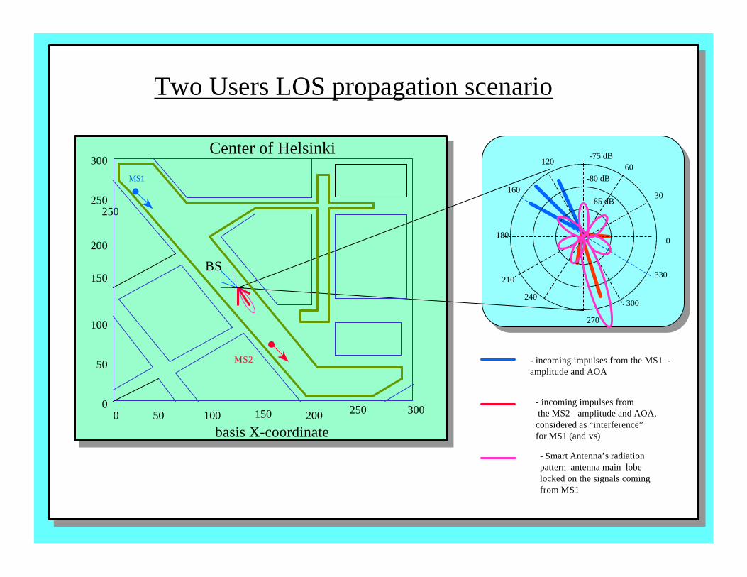
MS2
Two Users LOS propagation scenario
Center of Helsinki
BS
MS1
0180
-75 dB
-85 dB
-80 dB
30
60120
160
210
240
270
300
330
- incoming impulses from the MS1 -amplitude and AOA
- Smart Antenna’s radiationpattern antenna main lobelocked on the signals comingfrom MS1
- incoming impulses from the MS2 - amplitude and AOA,considered as “interference”for MS1 (and vs)
300
250
200
150
250
100
50
00 50 100 150 200 250 300
basis X-coordinate

5/6/99 62
4. NetSim specification
Platform: UNIX, Windows under development
Language: C
NetSim Voice and Data services, Smart Antennas,can Packet Switched , Circuit switchedsimulate: Different users behavior and their spatial distribution Radio
Network Control Functions (HO, admission, power control)
Simulation Capacity function of traffic, propagation, BS parameters and results: location. Network Control algorithms performance Location of problem areas Coverage prediction
Output ASCII format files can be easily read by information: MATLAB for statistical processing and visualization

5/6/99 63
5. Network Control with SA.
- Network control (initial access, HO, initial access, resource management )
- Packet transmission with SA
- FH with SA, fractional loading reuse ???
- DCA (AoA, link quality measurements, averaging)

5/6/99 64
5. Layer 1.Power control. Qualitymonitoring. Tracking.
- dynamic behavior of tracking , power control
- physical ch. structure, down-link problem FDD/TDD
- user identification problem to support SDMA individual color codes needed to support each SDMAtraffic channel channel
- for “rescue” omni directional channel for call recoveryis proposed

5/6/99 65
5. Layer 2. Initial access. Handover.
BS BS BS
-location aware HO or through omni-directional channel ?
- initial access with omni dir. ch. further narrow beam
- to setup beamformer just beforeuser dedicated channel is allocated (access proceduremodification or increasing access are proposed)
- how to make down-link BF when ch. info at up-linkis not available yet (tempor. omni DL or longer acces)
Initial access
t
5/6/99 66
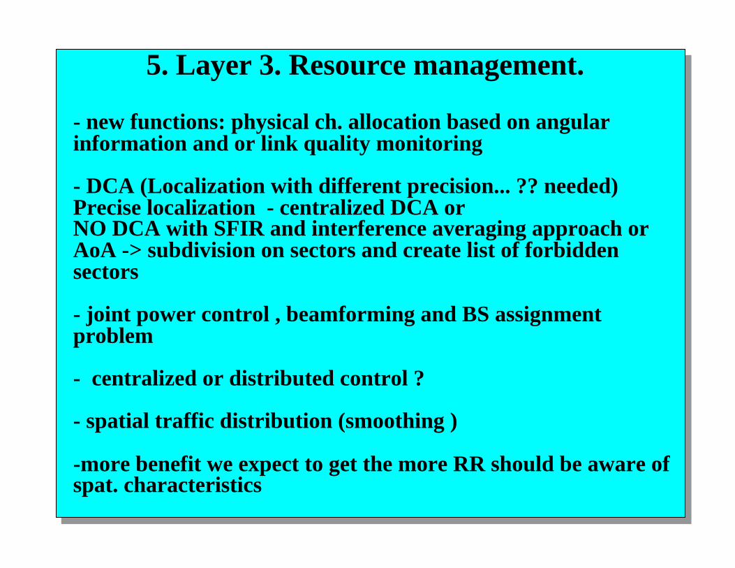
5. Layer 3. Resource management.
- new functions: physical ch. allocation based on angularinformation and or link quality monitoring
- DCA (Localization with different precision... ?? needed)Precise localization - centralized DCA orNO DCA with SFIR and interference averaging approach orAoA -> subdivision on sectors and create list of forbiddensectors
- joint power control , beamforming and BS assignmentproblem
- centralized or distributed control ?
- spatial traffic distribution (smoothing )
-more benefit we expect to get the more RR should be aware ofspat. characteristics

5/6/99 67
5. Network Control with SA. Higher layers.Geolocation.
New service (991, transport control…)
Combined DOA measurements and time delay based approach
Raytheon proposed commercial available geolocation system (SA option is included)

5/6/99 68
3-G network control with SA
- some loose form of synchronization between cells may required for ref. signal based BF
- user dedicated pilot channel or reference bits(implemented) - combination with link adaptation (since at the beginning“channel history” is not available. This combination will increase “soft capacity limit”
- Packet mode and DTX can create difficulties for BFdue to the “silence periods”
- With DTX downlink channel required during silence per.
-

5/6/99 69
6. Topics for Further Research
Smart Ant. Tech.
Network Planning-
Radio Network Management
C U
Radio interface-Receiverstructure-Tx, Rx alg.
AirInterface
DSP tech.
Packet transfer ,GPRS, EDGE
WirelessATM
relaying
SA at MS
mobile localization
UMTS radio network planning with SA
Receiver structures and Rx,Tx algorithms for different types of UMTS environments
Hierarchical CDMA cells architecture with SA
Study performance of the radio networkcontrol algorithms with smart antennas (initial access, HO, quality control)
Resource management.Joint power control,BS assignment, S-T algorithms.
Smart Antennas in Wireless ATM
Packet transmission in UMTS Radio Network with Smart Antennas
S-T coding

5/6/99 70
System integration of Smart Antennas technology in to UMTS environments
- Resource management. Joint power control , BS assignment, S-T algorithms. - Hierarchical CDMA cells architecture with SA.
- UMTS radio network planning with SA. GSM network planning (SFIR )
- Packet transmission in UMTS Radio Network with Smart Antennas at BS.
- GPRS and EDGE with SA
- Study optimal receiver structures and Rx,Tx algorithms for different types of UMTS environments.
- Study performance of the radio network control algorithms with SA (initial access, HO, quality control).
- S-T coding.
6. Research topics

5/6/99 71
Designer Airinterface
Antenna (M)
SA Receiver algorithm Remarks Ref.
SA experimental systems Ericsson & Mannesmann Mobilfunk )
GSM/DCS1800
8 Up-link: DOBDown-link: DOA switched-beamand adaptive
Several BS equippedwith SA integratedinto network
[41]
EricssonResearch(SW/US)
IS - 136(D-AMPS)
spacingup-link15λ &pol. div.
Up-link: MRC and IRC,Down-link:fixed beam approach
[43]
AT&T Labs-Research (US)
IS-136 4 Up-link: 4 branch adaptive TRB,DMI algorithmDown-link: switched beam withor without PC (up to 3 beams)
Up and down linksare independent
[45]
NTT DoCoMo(Japan)
UMTS 6 Up-link: Decision directed MMSE(tentative data and pilot)4 finger 2D-RAKEDown-link: calibration of weightsgenerated for reverse link
-include 3 cell sites-data transmissionup to 2 Mbps
[47]
TSUNAMI(SUNBEAM)Consortium (EU)
DECT ->SDMA->DCS1800
ULA_MUSIC for DOA estimationKalman Filtering for tracking
SDMA wasStudied based onDECT
[48]
CNET & CSF-THOMPSON (F)
GSM/DCS180SDMA
10circular
Up-link: DOA based BFCapon , MUSIC for DOA estim.Down-link: DOA based BF
[49]
UppsalaUniversity (SW)
DCS 1800SDMA
10circular
Up-link only: TRB with SMI Data traffic fromDCS-1800 was used
[50]
Commercially available productsMetawave (US)SpotlightTM2000
AMPS,CDMA
12 Up- and down links :12 switched beam
[51]
Raytheon (US) Flexibleupgradedby SW
8 Up-link: DOB based algorithm (?) SA can beconnected to RFinput at the BS
[52]
ArrayComm"IntelliCell"(US)
WLL, PHS,GSM
4 Up-link: ESPRITAdaptive interference cancellation
First mass marketcommercial product
[53]
7.