System Architecture Virtual Integration SAVI AFE...
20
System Architecture Virtual Integration SAVI AFE 61S1 Report Summary Final Report Release: Public Release Document ID: SAVI-AFE61S1-05-002 Related AFE Task: Task 5: Management Date: 3/9/2015 Issue: Version 0.4 Author(s): J. J. Chilenski M. S. Kerstetter Approved: SAVI PMC 3/9/2015 Aerospace Vehicle Systems Institute 3141 TAMU – HRBB #754 College Station, TX 77843-3141 Office: +1-979-845-5568 FAX: +1-979-339-4079 Web: www.avsi.aero CONFIDENTIALITY WARNING: This document contains proprietary and/or privileged information of the Aerospace Vehicle Systems Institute / Texas A&M Engineering Experiment Station. The confidentiality of the information herein must be protected per the terms of the AVSI Cooperative Agreement concerning Project Technology and may not be released outside of the relevant Participating Member organizations without the express approval of the Project Management Committee.
Transcript of System Architecture Virtual Integration SAVI AFE...
System Architecture Virtual Integration
SAVI AFE 61S1 Report Summary Final Report
Release: Public Release Document ID: SAVI-AFE61S1-05-002
Related AFE Task: Task 5: Management Date: 3/9/2015
Issue: Version 0.4
Author(s): J. J. Chilenski
M. S. Kerstetter
Approved: SAVI PMC
3/9/2015
Aerospace Vehicle Systems Institute 3141 TAMU – HRBB #754 College Station, TX 77843-3141 Office: +1-979-845-5568 FAX: +1-979-339-4079 Web: www.avsi.aero
CONFIDENTIALITY WARNING: This document contains proprietary and/or privileged information of the Aerospace Vehicle Systems Institute / Texas A&M Engineering Experiment Station. The confidentiality of the information herein must be protected per the terms of the AVSI Cooperative Agreement concerning Project Technology and may not be released outside of the relevant Participating Member organizations without the express approval of the Project Management Committee.

CONFIDENTIALITY WARNING: This document contains proprietary and/or privileged information of the Aerospace Vehicle
Systems Institute / Texas A&M Engineering Experiment Station. The confidentiality of the information herein must be protected per the terms of the AVSI Cooperative Agreement concerning Project Technology and may not be released outside of the relevant Participating Member organizations without the express approval of the Project Management Committee.
Page ii
Document Revisions REV DATE Author(s) Modifications Approved 0.1 2/25/2015 Outline only; moved to new template 0.2 5/1/2015 MSK Built the TOC, LOF and Applicable Documents 0.3 5/5/2015 MSK Incorporated last edits from JJC and DTW 0.4 5/7/2015 MSK Incorporated edits from AM, KW, GP, and SM.

CONFIDENTIALITY WARNING: This document contains proprietary and/or privileged information of the Aerospace Vehicle Systems Institute / Texas A&M Engineering Experiment Station. The confidentiality of the information herein must be protected per the terms of the AVSI Cooperative Agreement concerning Project Technology and may not be released outside of the relevant Participating Member organizations without the express approval of the Project Management Committee.
Page 1
Table of Contents
Document Revisions .......................................................................................................................................... ii
Table of Contents .............................................................................................................................................. 1
List of Figures .................................................................................................................................................... 1
Executive Summary ........................................................................................................................................... 2
Applicable Documents ....................................................................................................................................... 3
1 Introduction .................................................................................................................................................. 4
1.1 SAVI VIP Version 1.0 Development Roadmap ............................................................................................. 4
2 SAVI VIP Version 1.0A Summary ................................................................................................................ 6
2.1 VIP Specification ............................................................................................................................ 6
2.1.1 Domain Model ......................................................................................................................... 7
2.1.2 Use Cases ............................................................................................................................... 7
2.2 Model Repository/Data Exchange Layer (MR/DEL) Specification ................................................... 7
2.2.1 Components of SAVI Data Management ................................................................................. 7
2.2.2 Model Set ................................................................................................................................ 8
2.2.2.1 Requirements Model .................................................................................................... 8
2.2.2.2 Publisher/Subscriber Model ......................................................................................... 8
2.2.2.3 SysML and AADL Models with Translation ................................................................... 8
2.2.2.4 Solid Geometry Models ................................................................................................ 8
3.1 Mature and Extend the VIP Capabilities ......................................................................................... 9
3.2 Integrate ISO 10303-239 (PLCS) into the SAVI VIP ..................................................................... 10
3.3 Develop and Demonstrate Initial “Fit” Analysis Capabilities .......................................................... 12
3.4 Initial Behavior Consistency Checks and Integrated Behavior Analysis ........................................ 14
3.5 Manage SAVI Version 1.0B Development .................................................................................... 16
4 Conclusions and Recommendations .......................................................................................................... 18
4.1 Conclusions .................................................................................................................................. 18
4.2 Recommendations ....................................................................................................................... 18
List of Figures
Figure 1 SAVI VIP Version 1.0 incremental development roadmap ................................................................... 5
Figure 2 SAVI VIP capability growth tree ........................................................................................................... 6
Figure 3 Product Life Cycle Support (PLCS) DEX components ....................................................................... 11
Figure 4 Showing the “logical” and physical properties are consistent ............................................................. 13
Figure 5 Simple Sliding Mass System .............................................................................................................. 15

CONFIDENTIALITY WARNING: This document contains proprietary and/or privileged information of the Aerospace Vehicle Systems Institute / Texas A&M Engineering Experiment Station. The confidentiality of the information herein must be protected per the terms of the AVSI Cooperative Agreement concerning Project Technology and may not be released outside of the relevant Participating Member organizations without the express approval of the Project Management Committee.
Page 2
Executive Summary
This document summarizes the second year of development by the System Architecture Virtual Integration (SAVI) project of an initial Virtual Integration Process (VIP) designed as a “game-changing” shift toward early life-cycle verification within an architecture-centric model-based systems engineering (MBSE) process for the development of complex aerospace systems. During the first year of development, the SAVI team concentrated on use cases surrounding the Preliminary System Safety Analysis (PSSA) [3] of a simplified Wheel Braking System (WBS) based on the example in the SAE AIR 6110 [18] document within a procurement trade study. During this second year of initial VIP development, the team looked into use cases surrounding two additional capabilities.
The initial focus of this year’s effort was on producing and demonstrating an initial capability within the SAVI VIP to generate system-wide analyses of geometric and logical interfaces (categorized as “fit” in this context) for a representative small avionics assembly. This approach allowed the SAVI team to take the first concrete steps toward using the SAVI Model Repository/Data Exchange Layer (MR/DEL) as a standardized means of exchanging data within the VIP. Moreover, this “fit” work led to a much closer tie with the evolving MoSSEC standards group [20], which appears well-aligned with SAVI purposes and objectives.
The remainder of this year’s effort focused on producing a set of models to allow both domain-specific analyses and system level analyses for behavioral aspects of representative systems. This behavioral category of integration issues was, as it was anticipated, a rather difficult group of problems. While “fit” analysis is able to look at a set of static properties, behavior analysis additionally needs to look at the dynamic response of a system over time.
The behavior-oriented effort started by looking into extending the WBS from last year to include auto-brake and antiskid. This led to several problems. First, simply obtaining or generating a complete model set took more time than originally expected. Second, the complexity of the expanded WBS in terms of behavior analysis was too great to handle with no prior experience. This led the team to start with a simpler physical system.
A simple sliding mass system was chosen as a good vehicle for learning and developing basic principles. This system consisted of a sliding mass on a flat, horizontal surface moved by an actuator along a single axis of movement. This simplification allowed the SAVI working group to concentrate on differences between specific modeling tools (assumptions, computational techniques, etc.). It also allowed a more careful look at how consistency checks between various models, modeling assumptions and their interfaces need to be conducted to support early verification of the system behavior and underpin the expected system level behavior analysis. Multi-model co-simulation was also investigated as a way of performing early virtual integration analysis.
Finally, the behavior team looked at the push button selection of auto-braking mode. This allowed them to look into the use of model checking to perform both safety-related behavior checks and consistency checking.
Behavioral virtual integration issues demand intelligent use of the MR/DEL in more complex ways than the “fit” effort suggested and a much broader cooperation with several of the MoSSEC principals is anticipated to accommodate comprehensive behavioral consistency checks and integrated system behavior analyses. It is still expected that a more complicated physical set of models for the SAE AIR6110-based WBS example [18, 19] will suffice for this typical system behavioral integration in a SAVI environment. The semi-automated technique to carry out system safety analyses like the Preliminary System Safety Analysis (PSSA) [23] that was completed during year one of the SAVI VIP development was expanded to show an approach to conducting Common Mode Analysis (CMA). This effort was a straight-forward extension of last year’s work but it also introduced some new software tools that have potential for future exploitation [15].
The SAVI team has also revised two initial specifications, one for the VIP and one for its two major supporting infrastructure enablers, the Model Repository and the Data Exchange Layer, giving both of these documents additional structure and detail [4, 7]. In addition, an initial draft of the VIP process specification was prepared.
This work has provided a firm foundation for continuing efforts in AFE61S2 which is expected to culminate in a demonstration illustrating several foundational SAVI goals and principles including use of standards for data exchange with commercial-strength tools, intellectual property protection, consistency checking and early detection of errors at OEM and sub-tier levels.

CONFIDENTIALITY WARNING: This document contains proprietary and/or privileged information of the Aerospace Vehicle Systems Institute / Texas A&M Engineering Experiment Station. The confidentiality of the information herein must be protected per the terms of the AVSI Cooperative Agreement concerning Project Technology and may not be released outside of the relevant Participating Member organizations without the express approval of the Project Management Committee.
Page 3
Applicable Documents
[1] Avizienis, A., Laprie, J., Randell, B. and Landwehr, C., “Basic Concepts and Taxonomy of Dependable and Secure Computing”, IEEE Transactions on Dependable and Secure Computing, Vol. 1, No. 1, Jan-Mar 2004.
[2] “Technology Readiness Assessment Guidance”, Department of Defense, Assistant Secretary of
Defense for Research and Engineering (ASD(R&E)), April 2011 (Revision posted 13 May 2011).
[3] Chilenski, J. J. and Ward, D. T., “SAVI AFE 61 Report, Summary Final Report,” AFE 61 Report SAVI-AFE61-04-001, Aerospace Vehicle Systems Institute, 12 March 2014.
[4] vanHorn, S. B., Chilenski, J. J., and Ward, D. T., “Updated SAVI Virtual Integration Process (VIP) Specification,” AFE 61S1 Report SAVI-AFE61S1-01-001, Aerospace Vehicle Systems Institute, 23 April 2015.
[5] http://www.plcs.org/plcslib/plcslib/sys/dex_index_base.html
[6] http://www.plcs.org/plcslib/plcslib/
[7] Pollari, G. M., Chilenski, J. J., and vanHorn, S. B., ”SAVI Model Repository/Data Exchange Layer (MR_DEL) Specification (Updated)”, AFE 61S1 Report SAVI-AFE61S1-02-001, Aerospace Vehicle Systems Institute, 13 March 2015.
[8] Horta, B. M., Chilenski, J. J., and Ward, D. T., “Background Document for SAVI Standard”, AFE 61S1 Report, SAVI-AFE61S1-05-001, Aerospace Vehicle Systems Institute, 13 March 2015.
[9] http://www.epmtech.jotne.com/products.242624.no.html
[10] http://www.oasis-oslc.org
[11] Pollari, G. M., Chilenski, J. J., and vanHorn, S. B., “Fit Capability for SAVI VIP”, AFE 61S1 Report SAVI-
AFE61S1-03-001, Aerospace Vehicle Systems Institute, 13 March 2015.
[12] “Authority For Expenditure AFE 61S1 – Virtual Integration Process – SAVI Version 1.0B,” Aerospace Vehicle Systems Institute, 17 Jan 2014.
[13] “Authority For Expenditure AFE 61S2 – SAVI 1.0C”, Aerospace Vehicle Systems Institute, 1 Feb 2015.
[14] Woodham, K., Neto, F. C., Delange, J., and Hall, B., “Simple Sliding Mass System to Illustrate Behavioral Modeling”, AFE 61S1 Report SAVI-AFE61S1-04-005, Aerospace Vehicle Systems Institute, 12 March 2015.
[15] Delange, J., Feiler, P., Hall, B., Horta, B. M., Lewis, B., and Woodham, K., “Enhanced Wheel Brake System Model with Safety and Behavior Validation”, AFE 61S1 Report SAVI-AFE61S1-04-004, Aerospace Vehicle Systems Institute, 12 March 2015.
[16] Backes, J., “Resolute: An Assurance Case Language for Architecture Models”, High Integrity Language Technology, ACM SIGAdas Annual International Conference, 2014.
[17] Neto, F. C., Horta, B. M., Woodham, K., Delange, J., and Hall, B., "Wheel Braking System Model in Simulink", AFE 61S Report SAVI-AFE61-04-003, Aerospace Vehicle Systems Institute, 13 March, 2015.
[18] SAE AIR6110, “Contiguous Aircraft/System Development Process Example,” SAE International, December 2011.
[19] Chilenski, J. J., Hall, B., Oliveira, F., “Model Set Defining AIR 6110 Braking System Example,” SAVI-AFE61-03-001, AVSI, March 15, 2014.
[20] http://www.asd-ssg.org/mossec

CONFIDENTIALITY WARNING: This document contains proprietary and/or privileged information of the Aerospace Vehicle Systems Institute / Texas A&M Engineering Experiment Station. The confidentiality of the information herein must be protected per the terms of the AVSI Cooperative Agreement concerning Project Technology and may not be released outside of the relevant Participating Member organizations without the express approval of the Project Management Committee.
Page 4
1 Introduction
This document summarizes the results of the development activities carried out by the SAVI program during 2014, with Authorization for Expenditure (AFE) 61S1 serving as the governing project description. This was the second year of operational development for SAVI resulting in SAVI Version 1.0B. Concise task statements for this development phase include:
Mature and extend the VIP capabilities beyond the operational constraints of SAVI VIP Version 1.0A
Integrate an ISO 10303-239 Product Life Cycle Standard (PLCS) Data Exchange Specification (DEX) into the SAVI VIP that is the foundation for intermediate exchange of information between differing model types and all actors in the VIP
Develop and demonstrate initial “fit” analysis capabilities
Develop an initial methodology for initial behavior consistency checks and integrated behavior analysis within the SAVI VIP
Manage SAVI Version 1.0B Development
After spending one full year focused on system safety analysis capability, the SAVI Program Management Committee (PMC) chose to stress two additional aspects of system integration during the 2013-2014 efforts: (1) “fit” capability and (2) behavioral capability. The choices were pragmatic in that the team believed it could make considerable progress in the somewhat less complicated “fit” area rather than putting full concentration of limited SAVI resources into the behavioral area. Progress was deemed essential to obtaining continued support for the incremental development of SAVI and previous initial exploration of the behavioral issues had suggested that initial capability in this aspect of the VIP was too broad to complete in one year.
Moreover, as noted in all previous documentation of the project, the incremental development approach is based on the premise that SAVI participation will continue to grow. As Figure 1 on the following page shows, the project team has been constrained throughout the VIP development time (since 2008) with a shortfall in the resources needed to complete needed research objectives. Fortunately, three new members were added at the conclusion of the AFE and their contributions to the follow-on AFE are greatly anticipated. Even with this additional participation, SAVI’s continued under-participation will continue to affect the development progress for SAVI initial capability.
1.1 SAVI VIP Version 1.0 Development Roadmap
Feasibility demonstrations completed in 2012 and 2013 laid the foundation for the first phase of capability development for Version 1.0 of the SAVI VIP. Version 1.0 of the VIP is being developed over a four-year period and is targeted to provide capability aimed primarily at integration efforts for system integrators (OEMs) and first level (Tier 1) suppliers. Figure 1 illustrates the phasing for SAVI Version 1.0 development, which is currently set to take place over approximately four years’ time (SAVI Versions 1.0A, 1.0B, 1.0C, and 1.0D). During this development period the number of participants is assumed to grow from 10 to 22 participants. Two additional tool vendor participants (TVPs) were added during the last quarter of 2013. Late in the work on SAVI 1.0B (2014-2015), three new participants joined the effort, bringing the total number of participants to 14.

CONFIDENTIALITY WARNING: This document contains proprietary and/or privileged information of the Aerospace Vehicle Systems Institute / Texas A&M Engineering Experiment Station. The confidentiality of the information herein must be protected per the terms of the AVSI Cooperative Agreement concerning Project Technology and may not be released outside of the relevant Participating Member organizations without the express approval of the Project Management Committee.
Page 5
Figure 1 SAVI VIP Version 1.0 incremental development roadmap
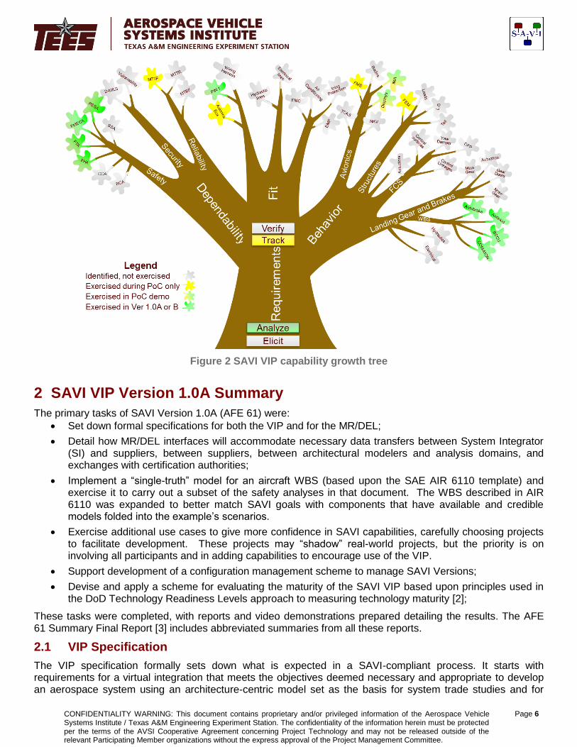
In addition to the development roadmap, carefully structured use cases designed to demonstrate SAVI’s capabilities were utilized during both the Proof of Concept phase and during the first two years of development of the SAVI VIP (Version 1.0A&B). Figure 2 depicts the capabilities that exist and offers a simple visualization of additional capabilities that must be added. The legend explains the color coding and the graphic captures four classes of capabilities needed to develop an aircraft system along with a qualitative assessment of the current maturity of the VIP. The Use Case methodology used during AFE 61 strongly influenced this “capability tree”. This graphic is the latest modification approved by the PMC during AFE 61S1 (SAVI 1.0B) and shows a Dependability branch that includes Safety, Reliability, and Security branches. This change was made to conform to the IEEE definition of Dependability [1] and has the added advantage of elevating the importance of security (especially in light of growing concerns of cybersecurity within systems with large amounts of embedded software).
CONFIDENTIALITY WARNING: This document contains proprietary and/or privileged information of the Aerospace Vehicle Systems Institute / Texas A&M Engineering Experiment Station. The confidentiality of the information herein must be protected per the terms of the AVSI Cooperative Agreement concerning Project Technology and may not be released outside of the relevant Participating Member organizations without the express approval of the Project Management Committee.
Page 6
Figure 2 SAVI VIP capability growth tree
2 SAVI VIP Version 1.0A Summary
The primary tasks of SAVI Version 1.0A (AFE 61) were:
Set down formal specifications for both the VIP and for the MR/DEL;
Detail how MR/DEL interfaces will accommodate necessary data transfers between System Integrator (SI) and suppliers, between suppliers, between architectural modelers and analysis domains, and exchanges with certification authorities;
Implement a “single-truth” model for an aircraft WBS (based upon the SAE AIR 6110 template) and exercise it to carry out a subset of the safety analyses in that document. The WBS described in AIR 6110 was expanded to better match SAVI goals with components that have available and credible models folded into the example’s scenarios.
Exercise additional use cases to give more confidence in SAVI capabilities, carefully choosing projects to facilitate development. These projects may “shadow” real-world projects, but the priority is on involving all participants and in adding capabilities to encourage use of the VIP.
Support development of a configuration management scheme to manage SAVI Versions;
Devise and apply a scheme for evaluating the maturity of the SAVI VIP based upon principles used in the DoD Technology Readiness Levels approach to measuring technology maturity [2];
These tasks were completed, with reports and video demonstrations prepared detailing the results. The AFE 61 Summary Final Report [3] includes abbreviated summaries from all these reports.
2.1 VIP Specification
The VIP specification formally sets down what is expected in a SAVI-compliant process. It starts with requirements for a virtual integration that meets the objectives deemed necessary and appropriate to develop an aerospace system using an architecture-centric model set as the basis for system trade studies and for

CONFIDENTIALITY WARNING: This document contains proprietary and/or privileged information of the Aerospace Vehicle Systems Institute / Texas A&M Engineering Experiment Station. The confidentiality of the information herein must be protected per the terms of the AVSI Cooperative Agreement concerning Project Technology and may not be released outside of the relevant Participating Member organizations without the express approval of the Project Management Committee.
Page 7
repetitively carrying out consistency checks at each iteration in the architectural design and subsequent model-based system engineering processes.
2.1.1 Domain Model
Delineation of the specification began with laying out a SysML domain model to guide the selection of use cases and, flowing from these use cases, the requirements for the VIP. The domain model serves as the collection point for what is to be included in the VIP and therefore guides the specification of that process. Four use cases and five requirements for the VIP are defined in the domain model. There are still open questions about what should and what should not be included in this model which will be resolved as the development of the VIP progresses and more capabilities are exercised.
2.1.2 Use Cases
The next step in generating this specification was to select use cases essential to the capability being added to the VIP. Since this was the first operational capability and since it is focused on system safety analysis at the early stages of the development cycle, the use cases chosen were centered on use of the VIP to set up a system architecture that allows interaction between all members of the development team and facilitates trade studies to select appropriate elements. Detecting and correcting defects at requirements definition rather than later during verification and validation testing is crucial to success or failure. Detection and correction of anomalies with the use of models and architectural analyses can be orders of magnitude less expensive and less time-consuming when the detection is made in the early life of a system.
With this motivation, the SAVI team set down four use cases that drive the VIP toward early detection of requirements errors and one use case that applies system safety analyses to a proposed system architecture:
Develop Proposed Architecture
Obtain Proposed Architectures
Perform Model Change Impact Analysis
Perform Consistency Checks
Perform Proposed System PSSA
These five use cases then lead logically to the five requirements defined for this first version of the VIP. Note that the first four of these are the requirements for the VIP in general and the last one is related to the demonstrations generated to illustrate VIP capabilities under AFE 61. Of course, this fifth use case is also generally necessary for systems development, but it is constrained to some extent to what the team did in 2013.
2.2 Model Repository/Data Exchange Layer (MR/DEL) Specification
The SAVI MR/DEL specification spells out high level requirements for the SAVI MR and DEL in executing the SAVI VIP. The VIP applies to a model set consisting of models from different domains, typically written in different modeling languages, having different data representations, and accessed with tools that may not inherently share data. But the SAVI VIP must ensure model consistency across this model set so that shared properties and dependencies have no contradictions – that is, the VIP must ensure consistency. The underlying information technology framework (MR and DEL) must support this single truth concept across the model set so that it starts integrated and stays integrated.
The high level requirements developed in this effort must be further decomposed and expanded to create testable, verifiable detailed requirements for an MR/DEL implementation during a given system development.
2.2.1 Components of SAVI Data Management
The two critical data management components are:
Model Repository (MR): a data structure needed for information storage and analysis of the reference model. It can also be defined as a container or place in which things (models, model initialization files, model products, etc.) can be stored [4].

CONFIDENTIALITY WARNING: This document contains proprietary and/or privileged information of the Aerospace Vehicle Systems Institute / Texas A&M Engineering Experiment Station. The confidentiality of the information herein must be protected per the terms of the AVSI Cooperative Agreement concerning Project Technology and may not be released outside of the relevant Participating Member organizations without the express approval of the Project Management Committee.
Page 8
Data Exchange Layer (DEL): the set of interfaces that allows data transfer between the elements and components of the SAVI repository structure and the various domain analysis tools [5]. A DEL can consist of data translators, data models, data file specifications, data schema, tools and processes for transporting and linking data and metadata.
2.2.2 Model Set
AFE 61 implemented a “single-truth” [8] model set based upon an aircraft WBS based upon the example in SAE AIR 6110.
2.2.2.1 Requirements Model
A Requirements Model was defined that was a representative subset of the functional and safety requirements for the WBS extracted from Air 6110. This requirements model traces from aircraft requirements through high level system requirements down to system requirements allocated to system items.
2.2.2.2 Publisher/Subscriber Model
A Publisher/Subscriber (Pub/Sub) model was created defining the major functional components of the WBS and the interconnections between them. This model identifies all components in the system of interest, interfacing connections between all components, “publishing” and “subscribing” information and “signal” type, among other details. The types used in this project include both power (electrical, hydraulic, and mechanical) and signal (input to an actuator or readings from a sensor). This model would form the basis of an interface control document (ICD) later in the project.
2.2.2.3 SysML and AADL Models with Translation
An initial functional system architecture model of the WBS was created in SysML using Enterprise Architect, version 10. This model was then translated into the detailed real-time embedded architectural model in AADL. SysML captures the logical and physical architecture views and AADL lays the foundation for formal analyses. In particular, the AADL was annotated with additional information supporting the safety analyses demonstrated during AFE 61.
In order to leverage these dissimilar languages, an AADL profile for SysML was developed during AFE 61. This profile was implemented in Enterprise Architect 10.0 so that SysML models could be constructed which would then be translated to AADL using an enhanced version of the DARPA META translator. This enhanced SysML-AADL translator was derived from the DARPA META program.
2.2.2.4 Solid Geometry Models
The AP214 Solid Geometry Model defines the location of the major system components and the routing of the interconnections between them in three-dimensional space. This model was produced using the Solid Works tool. Since not all member organizations in AFE 61 have this tool, it was exported from Solid Works in STEP AP203 format, read up into NX and exported in STEP AP214 format. AFE 61 is the first SAVI project that incorporated a solid geometry model into the model set. The main purpose for adding this solid geometry model is to facilitate inter-model consistency checks that deal with real-world implementation issues rather than only those that can be represented in an abstract functional or logical model.
2.2.3 Safety Analyses
In support of the PSSA conducted within the SAVI VIP, the following analyses were developed:
Fault Hazard Analysis (FHA) – automated generation of the FHA table off of the annotated AADL model.
Fault Tree Analysis (FTA) – automated generation of fault trees off of the annotated AADL model.
Failure Modes and Effects Analysis (FMEA) – automated generation of the FMEA from the annotated AADL model.
Common Cause Analysis (CCA) – automated generation of the CCA report from the annotated AADL model.
Reliability/Availability analysis – automated generation of the Reliability Block Diagram and

CONFIDENTIALITY WARNING: This document contains proprietary and/or privileged information of the Aerospace Vehicle Systems Institute / Texas A&M Engineering Experiment Station. The confidentiality of the information herein must be protected per the terms of the AVSI Cooperative Agreement concerning Project Technology and may not be released outside of the relevant Participating Member organizations without the express approval of the Project Management Committee.
Page 9
reliability report from the annotated AADL model.
In addition, an architectural trade study was conducted utilizing the five analyses to compare and contrast a federated architecture versus an integrated modular avionics (IMA) architecture for the WBS.
2.2.4 Demonstrations
The SAVI team generated four recorded demonstrations of how to use the SAVI VIP.
Automated FHA generation.
Automated FT generation and analysis.
Automated fault-impact analysis.
Automated inter-model consistency checking.
3 SAVI VIP Version 1.0B Summary
The four core tasks described in Section 1.0 provided the basis for developing Version 1.0B of the SAVI VIP over the period shown. During 2014, the team made healthy progress in extending and augmenting the capabilities developed in the previous AFE.
The primary tasks for AFE 61S1 (2014) were:
Mature and extend the VIP capabilities beyond the operational constraints of SAVI VIP Version 1.0A
Integrate an ISO 10303-239 PLCS DEX into the SAVI VIP that is the foundation for intermediate exchange of information between differing model types and all actors in the VIP
Develop and demonstrate initial “fit” analysis capabilities
Develop an initial methodology for initial behavior consistency checks and integrated behavior analysis within the SAVI VIP
Manage SAVI Version 1.0B Development
Each of these tasks and their deliverables will be described in the following sections.
3.1 Mature and Extend the VIP Capabilities
Additional research and development is necessary to improve robustness of the operational capabilities developed in the previous AFE. Under this task, specific attention was placed on refining the workflow through the AFE 61 analysis processes, including consistency checking between models; generation, archival, and retrieval of analysis results; and conducting change impact analysis.
The primary accomplishments from this effort were:
a. Documentation and Videos
Completed documentation of Version 1.0A capability with four narrated videos illustrating: (1) the VIP specification and its impact on a development project, (2) the main features and uses of the SAVI MR/DEL, (3) the character and capability of SAVI consistency checking, and (4) SAVI constructs as applied to generate a Preliminary System Safety Analysis (PSSA) for the modified aircraft WBS during 2013. The four story boards that were started during the close-out meeting for AFE 61 were completed early in the SAVI Version 1.0B effort.
b. Revision to SAVI 1.0A VIP Specification
The SysML Domain model forming the basis for the SAVI VIP Specification was updated with additional: (1) use cases for the “fit” and “behavior” capabilities; (2) requirements for the SAVI VIP, DEL and MR supporting “fit” and “behavior”; and (3) user needs from the SAVI participants. All these added capabilities must support architectural level analyses that detect software and hardware defects reliably and allow SAVI-compliant consistency checking of modifications to the models with the same or better integrity than that achieved under the SAVI Version 1.0A specification. The complete SAVI VIP specification to date can be found in [4].

CONFIDENTIALITY WARNING: This document contains proprietary and/or privileged information of the Aerospace Vehicle Systems Institute / Texas A&M Engineering Experiment Station. The confidentiality of the information herein must be protected per the terms of the AVSI Cooperative Agreement concerning Project Technology and may not be released outside of the relevant Participating Member organizations without the express approval of the Project Management Committee.
Page 10
c. Revision to SAVI 1.0A MR/DEL Specification
The SAVI MR/DEL Specification added robustness by: (1) formalizing the MR/DEL configuration specification by moving resolutely toward standards-based data exchange based upon ISO 10303-239 Product Life Cycle Standard (PLCS) Data Exchange Specifications [5, 6] as incorporated within MoSSEC [20]; (2) incorporating stronger and more formal protection of intellectual property and sensitive information within the VIP framework within the MR/DEL structure; (3) initiating “fit” capability within the SAVI MR/DEL to allow capture from geometry and architectural models necessary interconnections between avionics boards that must interface, whether they be from the same supplier or different suppliers; (4) and adding components to the AIR 6110 Wheel Braking System example to allow both static and dynamic behavioral analyses of system performance and SAVI-compliant consistency checking whenever modifications are made to cyber-physical components delineated in the architecture. Again, as with the revision to the VIP specification, additional capabilities must support architectural level analyses that detect hardware and software defects reliably and allow SAVI-compliant consistency checking of the modifications. The complete MR/DEL specification to date can be found in [7].
d. Document capturing an Initial SAVI Process Specification.
This document, [8], intends to give a high level and broad view of virtual integration processes. In its final form, this document will describe terminology, requirements, capabilities and processes for performing virtual integration as developed in SAVI program. Currently, this is a “living” document providing at this time an introduction and descriptions of topics developed through the end of AFE 61S1.
3.2 Integrate ISO 10303-239 (PLCS) into the SAVI VIP
The MR/DEL Specification describes the high level requirements for a SAVI MR and DEL. The SAVI VIP applies to a model set that consists of models from different domains using different modeling languages and data representations and accessed with different tools that do not necessarily share data. The SAVI VIP ensures model consistency across a model set so that shared properties and dependencies are in synch – that is, consistent. The underlying Information Technology framework (MR and DEL) must support this single truth across a model set so that it starts integrated and stays integrated.
The SAVI MR/DEL is one of the cornerstone enablers for SAVI inter-model consistency checking. SAVI consistency checking involves shared properties and relationships between models that don’t normally communicate due to different data representations, purpose, language, and tool implementations. Since data interoperability plays a key role in the SAVI consistency check, SAVI seeks to leverage existing standards to implement the MR and DEL.
A significant effort was expended under previous SAVI AFEs to identify the characteristics of an underlying language that could be used within the MR/DEL to map models and model data to/from various tool and analysis environments. These previous studies concluded emphatically that there is no specific language that could be used to universally accomplish this purpose. In AFE 61S1, SAVI explored the viability of using ISO 10303-239, or STEP AP-239, Product Life Cycle Support (PLCS) with a Data Exchange Specification (DEX) to provide the information exchange capability necessary for the VIP to function. This standards-based option appears very promising and the SAVI project team negotiated a TVP agreement with Eurostep Group to assist in expanding this capability in AFE 61S2. Integrating the preliminary DEX into the SAVI VIP was an important task for AFE 61S1 and sets the stage for future integration of other tools and model types within SAVI. There is also the potential for implementing a significant level of IP protection and data security with some of the tools suggested by Eurostep using the MoSSEC DEX under this ISO standard. Other tool vendors are also utilizing this standards-based approach to data exchange [9].
CONFIDENTIALITY WARNING: This document contains proprietary and/or privileged information of the Aerospace Vehicle Systems Institute / Texas A&M Engineering Experiment Station. The confidentiality of the information herein must be protected per the terms of the AVSI Cooperative Agreement concerning Project Technology and may not be released outside of the relevant Participating Member organizations without the express approval of the Project Management Committee.
Page 11
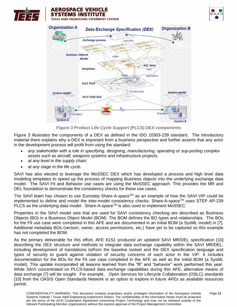
Figure 3 Product Life Cycle Support (PLCS) DEX components
Figure 3 illustrates the components of a DEX as defined in the ISO 10303-239 standard. The introductory material there explains why a DEX is important from a business perspective and further asserts that any actor in the development process will profit from using the standard:
any stakeholder with a role in specifying, designing, manufacturing, operating or sup-porting complex assets such as aircraft, weapons systems and infrastructure projects;
at any level in the supply chain;
at any stage in the life cycle.
SAVI has also elected to leverage the MoSSEC DEX which has developed a process and high level data modeling templates to speed up the process of mapping Business objects into the underlying exchange data model. The SAVI Fit and Behavior use cases are using the MoSSEC approach. This provides the MR and DEL foundation to demonstrate the consistency checks for these use cases.
The SAVI team has chosen to use Eurostep Share-A-spaceTM as an example of how the SAVI VIP could be implemented to define and model the inter-model consistency checks. Share-A-spaceTM uses STEP AP-239 PLCS as the underlying data model. Share-A-spaceTM is also used to implement MoSSEC.
Properties in the SAVI model sets that are used for SAVI consistency checking are described as Business Objects (BO) in a Business Object Model (BOM). The BOM defines the BO types and relationships. The BOs for the Fit use case were completed in this AFE and are documented in an initial BOM (a SysML model) in [7]. Additional metadata BOs (version, owner, access permissions, etc.) have yet to be captured so this example has not completed the BOM.
As the primary deliverable for this effort, AFE 61S1 produced an updated SAVI MR/DEL specification [10] describing the DEX structure and methods to integrate data exchange capability within the SAVI MR/DEL, including development of translations to/from the baseline toolset and the DEX specification language and types of security to guard against violation of security concerns of each actor in the VIP. It includes documentation for the BOs for the Fit use case completed in the AFE as well as the initial BOM (a SysML model). This update incorporated all lessons learned from the “fit” and “behavior” work performed this year. While SAVI concentrated on PLCS-based data exchange capabilities during this AFE, alternative means of data exchange [7] will be sought. For example, Open Services for Lifecycle Collaboration (OSLC) standards [10] from the OASIS Open Standards Network is an option to explore in future AFEs as available resources permit.
CONFIDENTIALITY WARNING: This document contains proprietary and/or privileged information of the Aerospace Vehicle Systems Institute / Texas A&M Engineering Experiment Station. The confidentiality of the information herein must be protected per the terms of the AVSI Cooperative Agreement concerning Project Technology and may not be released outside of the relevant Participating Member organizations without the express approval of the Project Management Committee.
Page 12
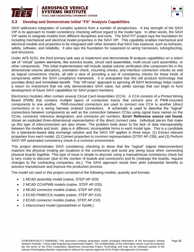
3.3 Develop and Demonstrate Initial “Fit” Analysis Capabilities
SAVI addresses integration of complex systems from a number of perspectives. A key strength of the SAVI VIP is its approach to model consistency checking without regard to the model type. In other words, the SAVI VIP seeks to integrate models from different disciplines and tools. The SAVI FIT project lays the foundation for including mechanical and electrical model properties in the SAVI VIP. This capability enables mechanical and electrical models and properties to be integrated with other domains that SAVI has explored, such as behavior, safety, software, and reliability. It also lays the foundation for expansion to wiring harnesses, tubing/ducting, and structures.
Under AFE 61S1, the third primary task was to implement and demonstrate fit analysis capabilities on a select set of “virtual” system elements, like avionics boxes, circuit card assemblies, multi-circuit card assemblies, or other components. This initial implementation will include spatial volume verification (the component fits in the dimensional volume allocation), orientation check, mounting checks, and interface connection checks as well as logical connections checks, all with a view of providing a set of consistency checks for these kinds of components within the SAVI compliance framework. It is anticipated that this will produce technology that provides direct and immediate benefit. This “off-ramp” approach to spinning off SAVI technology helps realize a return on investment that not only demonstrates SAVI value, but yields savings that can begin to fund development of future SAVI capabilities for SAVI project members.
Electronics modules often contain several Circuit Card Assemblies (CCA). A CCA consists of a Printed Wiring Board (PWB) that contains multiple layers of conductive traces that connect pins of PWB-mounted components to one another. PWB-mounted connectors are used to connect one CCA to another (direct connection) or to a wiring harness (indirect connection). A schematic is used to describe the “logical” connections between components as well as the connection between CCAs using signal trace names on the CCAs, connector reference designators, and connector pin numbers. Error! Reference source not found. shows an exploded three-dimensional representation of the direct connect case. Individual pieces that make up this type of interconnection are also shown. The problem boils down to the lack of data interoperability between the models and tools: data is in different, incompatible forms in each model type. This is a candidate for a standards-based data exchange solution and the SAVI VIP applies in three ways: (1) Extract relevant properties from each model, (2) Convert properties to common representation (STEP AP-239), and (3) Perform SAVI VIP automated consistency check in a common environment.
This project demonstrates SAVI consistency checking to show that the “logical” (signal interconnection) matches the physical (mating pin locations in the connectors) and avoid any wiring issue when connecting physical boards together. This type of issue is simple to discover using a manual/visual consistency check but is very costly to discover (due to the number of boards and connectors) and fix (redesign the boards, request changes to the contracting companies, etc.). The SAVI approach would then yield substantial benefits to avionics manufacturer and improve the production process.
The model set used in this project consisted of the following models, quantity and formats:
1 MCAD assembly model (native, STEP AP-203)
2 MCAD CCA/PWB models (native, STEP AP-203)
2 MCAD connector models (native, STEP AP-203)
2 ECAD PWB/CCA models (native, STEP AP-210)
2 ECAD connector models (native, STEP AP-210)
1 Interconnect model (spreadsheet or SysML)

CONFIDENTIALITY WARNING: This document contains proprietary and/or privileged information of the Aerospace Vehicle Systems Institute / Texas A&M Engineering Experiment Station. The confidentiality of the information herein must be protected per the terms of the AVSI Cooperative Agreement concerning Project Technology and may not be released outside of the relevant Participating Member organizations without the express approval of the Project Management Committee.
Page 13
Figure 4 Showing the “logical” and physical properties are consistent
In current industry practice, a manual, visual process is used to make sure that signals on one CCA are connected to the correct signals on the other CCA. This project defined a series of automated SAVI consistency checks that would replace the manual, visual checks currently in use. The MR/DEL is using the following standards and tool:
ISO 10303 STEP (AP-203, AP-210)
ISO 10303 AP239 PLCS
MoSSEC BOM & DEX
Eurostep Share-A-space
SAVI seeks to use existing tools and standards where possible. For this use case, the STEP AP-239 data interoperability standard is leveraged through the MoSSEC DEX (Data Exchange Specification) as implemented in the Eurostep Share-A-space™ collaboration hub. Reference [11] provides a more detailed description of how this tool was utilized.
The SAVI VIP is being extended to use the above standards and tool to perform the following three steps:
Contacts
Connector Pins
Contacts
Connector Pins
Terminals
PCB Pads
PCB Signal Traces
PCB Pads
PCB Signal Traces
PCB (Printed Circuit Board
PCB (Printed Circuit Board
Terminals
Physical
Logical
CONFIDENTIALITY WARNING: This document contains proprietary and/or privileged information of the Aerospace Vehicle Systems Institute / Texas A&M Engineering Experiment Station. The confidentiality of the information herein must be protected per the terms of the AVSI Cooperative Agreement concerning Project Technology and may not be released outside of the relevant Participating Member organizations without the express approval of the Project Management Committee.
Page 14
Extract relevant properties from each model
Convert properties to common representation (STEP AP-239)
Perform SAVI VIP automated consistency check in a common environment (Eurostep Share-A-space)
In order to perform a consistency check, the set of properties in the model set are identified. These properties, or “Business Objects,” are identified in a SysML model diagram. The Business Objects for this use case (described in [7]) are mapped to the MoSSEC BOM. Additional metadata Business Objects (version, owner, access permissions, etc.) have yet to be captured and the Business Objects for “Coordinates” is not complete. Additional work will be done in the next phase of SAVI to refine this mapping.
This task delivered documentation of methods and steps used to perform the fit analysis, including development of any constraint algorithms used to implement the spatial violation, orientation and interface consistency checks.
The SAVI Fit project has made excellent progress under AFE 61S1. The problem is well understood and technologies and tools exist to meet the project goals defined in AFE 61S2. The business value is recognized and brings SAVI closer to realizing actual savings, which will help pay for future investment. This use case lays a structural foundation not only for geometry related models and properties, but for the information technology infrastructure to implement the tools and capabilities – scaled to an industrial setting.
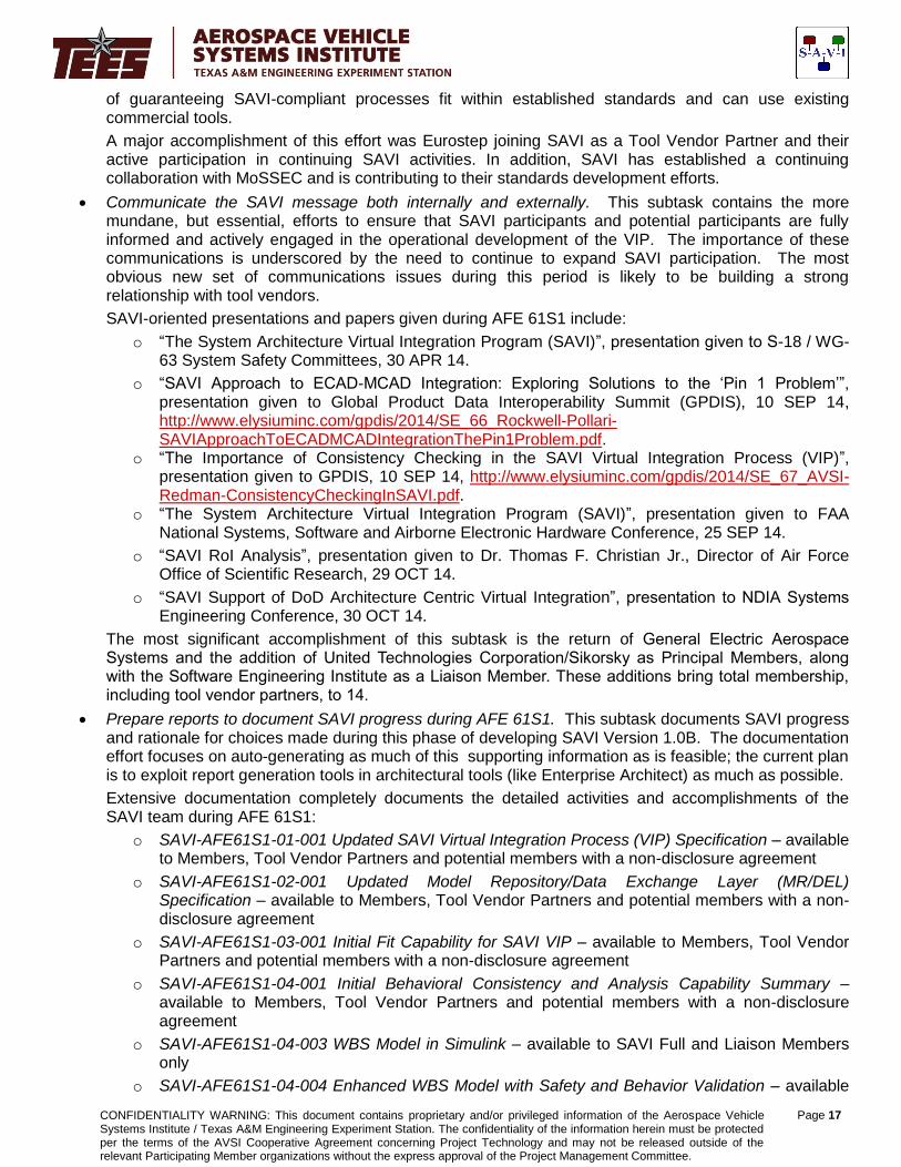
3.4 Initial Behavior Consistency Checks and Integrated Behavior Analysis
A primary objective of SAVI is to define a means (realized by a set of processes and tools) for performing virtual integration of a complex cyber-physical system in a multi-tiered environment [12, 13]. This virtual integration approach is intended to assist the system integrator by helping to identify integration issues early in the development project. The system is realized virtually through the use of a System Reference Model (SRM) assembled and queried through the SAVI MR/DEL.
The initial focus areas for SAVI address two specific integration concern viewpoints identified as “fit” and “behavior.”
“Fit,” as described in [11], addresses integration from the electro-mechanical perspective using:
Physical component geometry (volume, dimensions, orientation, etc.),
Physical connections (electrical signal paths, wiring harnesses, electronic interfaces, etc.), and
Physical interfaces (connector pin configurations, identifiers and orientations, mechanical mounts, etc.).
While “fit” represents system integration from what could be considered as a static perspective, “behavior” addresses the functional or dynamic response of the integrated system or its constituent elements. Because systems interact with the environment in which they operate, system behavior analysis often requires the characterization of the environment, and system/environment interfaces as well.
The term “behavior” implies a temporal system response given a set of initial conditions, input conditions and environmental conditions. The response may be observed as a time-trace, such as a plot of a position response of a dynamic system under control. Alternatively, aspects of the behavior can be expressed as behavioral property assertions that are not strictly a function of time. For instance, a property assertion can state a time-independent property (“the system position will never exceed X”), a general time property (“the system will eventually converge to steady state”), or time-bounded property (“the system will always transition to mode B within 10 seconds of a mode transition command”).
A major portion of AFE 61S1 was dedicated to examining analytical methods that can support SAVI behavior analysis, definition of SAVI model dependency registration and model-to-model consistency checks, requirements verification and design analysis. After initial examinations into the addition of consistency checking capability in the wheel braking system model, the development team concluded that the complexity of the WBS model set from AFE 61 masked the discovery of this process work flow. Therefore, a simpler sliding mass model incorporating a feedback control loop (Figure 5) was determined more useful as the first iteration in laying out the behavioral virtual integration steps for the VIP. The motivation for this is to provide a simple pathfinder example in support of the task objectives and provide some traction in scaling these processes to

CONFIDENTIALITY WARNING: This document contains proprietary and/or privileged information of the Aerospace Vehicle Systems Institute / Texas A&M Engineering Experiment Station. The confidentiality of the information herein must be protected per the terms of the AVSI Cooperative Agreement concerning Project Technology and may not be released outside of the relevant Participating Member organizations without the express approval of the Project Management Committee.
Page 15
the scope of a realistic aircraft system such as the WBS.
Figure 5 Simple Sliding Mass System
Behavioral consistency checking as described in [14] distinguishes between consistency checking of behavior model properties (parameter values contained within the behavior model) and checking that the behavioral response of two or more models are equivalent.
Behavior consistency checks in [14] were further decomposed into:
Data value consistency
Model property consistency
Model behavior consistency (time-history)
Model behavior consistency (property assertion)
Models used in this exercise were expressed in different modeling languages, specifically, SysML, AADL, Simulink, and Modelica. As a part of this exercise, the team developed and demonstrated a system model that used a Functional Mockup Unit (FMU) of the system dynamics in a co-simulation with the Scilab control system. This was introduced as a proof-of-concept to illustrate that system behavior checking may not necessarily be between two models, but between system models that are themselves composed from a diverse model set. Ref [14] goes on to discuss at a high level some implications of co-simulation to behavior consistency checking.
Additional work on the representative WBS model, documented in [15], centered on requirements analysis verification using Resolute. A set of general, Brake and Steering Control Unit (BSCU), and hydraulic system requirements as a notional specification of the WBS were compiled, and then were restated in the form of Resolute theorems.
The hierarchical set of WBS requirements was processed by Resolute and, as noted in [15], the Resolute analysis failed when applied to a non-redundant architecture, violating requirements mandating the use of redundancy. This initial exploratory proof of concept investigation illustrated the potential for integrated property analysis given an integrated model. For this specific analysis, it serves to illustrate that Resolute will identify inconsistencies between the requirements and the architecture model purported to be compliant with them.
Assume/guarantee relationships between components of an Architecture Analysis and Design Language (AADL) [16] model of a hypothetical WBS auto-brake mode selection panel were applied, captured from a real-

CONFIDENTIALITY WARNING: This document contains proprietary and/or privileged information of the Aerospace Vehicle Systems Institute / Texas A&M Engineering Experiment Station. The confidentiality of the information herein must be protected per the terms of the AVSI Cooperative Agreement concerning Project Technology and may not be released outside of the relevant Participating Member organizations without the express approval of the Project Management Committee.
Page 16
world system that suffered a failure in an aviation accident, and then processed the models and assume/guarantee relationships to demonstrate that the system components behaved consistently. Note that this initial proof of concept is implemented at a very high level of abstraction.
In addition to consistency checking at the model property and the model behavior level, and requirements verification analysis, work performed under AFE61S1 also addresses aspects of behavioral design analysis. Aspects of safety-oriented design analysis were also demonstrated, such as what would be used to support an ARP-4761 Preliminary System Safety Assessment (PSSA), by developing a Common Mode Assessment (CMA) plugin using the AADL Behavior Annex and demonstrating the use of the CMA plugin on the A-320 WBS.
During AFE61S1, an initial Simulink model of the WBS auto-brake and anti-skid system was developed to be used in closed-loop WBS behavior modeling. This model constitutes a major accomplishment within the AFE, and it provides a solid baseline for continued dynamic analysis of the WBS.
Progress on behavior analysis under AFE 61S1 provides a solid basis for achieving the behavior analysis objectives defined under AFE 61S2. The following general observations show that the behavior working group is well positioned to address the next phase of the work:
Consistency Checking documented in [14] and [15] shows the foundation for covering consistency checking relevant to data values within behavior models, model structure (components and connections), and behavioral consistency – both from a time-history and a property assertion perspective. Work to be performed in collaboration with Eurostep will pave the way for moving these checks from a proof-of-concept to regimented processes managed through the SAVI VIP MR/DEL. The team will also demonstrate during AFE 61S2 consistency checks of several models using requirements analysis.
Requirements Analysis documented in [15] using Resolute demonstrated an automated method for aspects of requirements verification on behavior models. SAVI is continuing to evaluate the best way to manage requirements and to address mode-based requirements verification. The team will exercise its requirements analysis tools in SAVI to check requirements enforcement and auto-generate assurance cases.
Design Analysis conducted under [15] demonstrates a preliminary proof-of-concept for conducting an aspect of the safety analysis through the development of a CMA plugin. Other types of analysis supporting the PSSA can be configured similarly within the open Eclipse tools and used to analyze system architecture models expressed in AADL.
The design analysis on the initial WBS model documented in [17] provides a solid analytical basis for integrating a comprehensive WBS model set to support AFE 61S2. In particular, the behavior working group is discussing potential ways to refactor the [17] model to integrate aspects of the computational system, and potentially parsing the physical dynamics into a separate model accessed through a co-simulation capability.
This study underscored the difference between “static” properties of the model (be they specific parameter values or properties defined and assess using AGREE), and the dynamic behavior of the executed model, such as through a time-domain simulation. In some instance, models may be dramatically different at the structural/architectural level, but have virtually identical responses to time-based input profile. In such a case, the models may be determined to be inconsistent (because they have different structures or parameter values) or consistent (because they have essentially equivalent response characteristics). This drives home the need for careful definition of consistency for a specific purpose.
3.5 Manage SAVI Version 1.0B Development
The management task covers all aspects of managing the SAVI Version 1.0B development effort:
Strengthen liaison with Tool Vendor Participants and establish partnership(s) with standards bodies. Tool vendors began working with SAVI during AFE 61 and SAVI explored collaboration with groups primarily interested in promoting standards for collaboration. A significant part of management efforts were expended in expanding these ties with PDES, INCOSE, and other standards groups, with the goal
CONFIDENTIALITY WARNING: This document contains proprietary and/or privileged information of the Aerospace Vehicle Systems Institute / Texas A&M Engineering Experiment Station. The confidentiality of the information herein must be protected per the terms of the AVSI Cooperative Agreement concerning Project Technology and may not be released outside of the relevant Participating Member organizations without the express approval of the Project Management Committee.
Page 17
of guaranteeing SAVI-compliant processes fit within established standards and can use existing commercial tools.
A major accomplishment of this effort was Eurostep joining SAVI as a Tool Vendor Partner and their active participation in continuing SAVI activities. In addition, SAVI has established a continuing collaboration with MoSSEC and is contributing to their standards development efforts.
Communicate the SAVI message both internally and externally. This subtask contains the more mundane, but essential, efforts to ensure that SAVI participants and potential participants are fully informed and actively engaged in the operational development of the VIP. The importance of these communications is underscored by the need to continue to expand SAVI participation. The most obvious new set of communications issues during this period is likely to be building a strong relationship with tool vendors.
SAVI-oriented presentations and papers given during AFE 61S1 include:
o “The System Architecture Virtual Integration Program (SAVI)”, presentation given to S-18 / WG-63 System Safety Committees, 30 APR 14.
o “SAVI Approach to ECAD-MCAD Integration: Exploring Solutions to the ‘Pin 1 Problem’”, presentation given to Global Product Data Interoperability Summit (GPDIS), 10 SEP 14, http://www.elysiuminc.com/gpdis/2014/SE_66_Rockwell-Pollari-SAVIApproachToECADMCADIntegrationThePin1Problem.pdf.
o “The Importance of Consistency Checking in the SAVI Virtual Integration Process (VIP)”, presentation given to GPDIS, 10 SEP 14, http://www.elysiuminc.com/gpdis/2014/SE_67_AVSI-Redman-ConsistencyCheckingInSAVI.pdf.
o “The System Architecture Virtual Integration Program (SAVI)”, presentation given to FAA National Systems, Software and Airborne Electronic Hardware Conference, 25 SEP 14.
o “SAVI RoI Analysis”, presentation given to Dr. Thomas F. Christian Jr., Director of Air Force Office of Scientific Research, 29 OCT 14.
o “SAVI Support of DoD Architecture Centric Virtual Integration”, presentation to NDIA Systems Engineering Conference, 30 OCT 14.
The most significant accomplishment of this subtask is the return of General Electric Aerospace Systems and the addition of United Technologies Corporation/Sikorsky as Principal Members, along with the Software Engineering Institute as a Liaison Member. These additions bring total membership, including tool vendor partners, to 14.
Prepare reports to document SAVI progress during AFE 61S1. This subtask documents SAVI progress and rationale for choices made during this phase of developing SAVI Version 1.0B. The documentation effort focuses on auto-generating as much of this supporting information as is feasible; the current plan is to exploit report generation tools in architectural tools (like Enterprise Architect) as much as possible.
Extensive documentation completely documents the detailed activities and accomplishments of the SAVI team during AFE 61S1:
o SAVI-AFE61S1-01-001 Updated SAVI Virtual Integration Process (VIP) Specification – available to Members, Tool Vendor Partners and potential members with a non-disclosure agreement
o SAVI-AFE61S1-02-001 Updated Model Repository/Data Exchange Layer (MR/DEL) Specification – available to Members, Tool Vendor Partners and potential members with a non-disclosure agreement
o SAVI-AFE61S1-03-001 Initial Fit Capability for SAVI VIP – available to Members, Tool Vendor Partners and potential members with a non-disclosure agreement
o SAVI-AFE61S1-04-001 Initial Behavioral Consistency and Analysis Capability Summary – available to Members, Tool Vendor Partners and potential members with a non-disclosure agreement
o SAVI-AFE61S1-04-003 WBS Model in Simulink – available to SAVI Full and Liaison Members only
o SAVI-AFE61S1-04-004 Enhanced WBS Model with Safety and Behavior Validation – available

CONFIDENTIALITY WARNING: This document contains proprietary and/or privileged information of the Aerospace Vehicle Systems Institute / Texas A&M Engineering Experiment Station. The confidentiality of the information herein must be protected per the terms of the AVSI Cooperative Agreement concerning Project Technology and may not be released outside of the relevant Participating Member organizations without the express approval of the Project Management Committee.
Page 18
to Members, Tool Vendor Partners and potential members with a non-disclosure agreement
o SAVI-AFE61S1-04-005 Simple Sliding Mass System to Illustrate Behavioral Modeling – available to SAVI members and Tool Vendor Partners
o SAVI-AFE61S1-05-001 Background Document for SAVI Standard – available to Members, Tool Vendor Partners and potential members with a non-disclosure agreement
o SAVI-AFE61S1-05-002 Summary Final Report – available to the general public
4 Conclusions and Recommendations
4.1 Conclusions
This report illustrates how the SAVI VIP was advanced during its second year of developing an operational set of capabilities. In this second year, effort was applied to two areas of concern: fit and behavior. As anticipated, incorporating behavior into the SAVI VIP turned out to be a challenge. Unfortunately, it turned out to be an even bigger challenge than anticipated. Nevertheless, progress was made. In keeping with the focus of last year, safety analyses were advanced during this year’s work.
The end of 2014 saw the return of General Electric Aerospace Systems and the addition of United Technologies Corporation/Sikorsky as Principal Members, along with the Software Engineering Institute as a Liaison Member. These additions bring total membership, including tool vendor partners, to 14. This is a very positive trend and is indicative of growing understanding of the importance and objectives of the SAVI program.
4.2 Recommendations
Engage more fully with related efforts. The Non-Advocate Review (NAR) conducted in November 2013 pointed strongly to the necessity of closer cooperation with other projects. While SAVI has attempted to stay in touch with a number of these efforts, there are others that need to be included as well.
More please! The Non-Advocate Review (NAR) conducted in November 2013 pointed strongly to the necessity of closer ties between all groups working on model-based engineering activities.
Ensure that current work does not conflict with overall MBSE developments. The success of this long term goal depends on the depth and breadth of MBSE knowledge that the SAVI team maintain; in that context, this recommendation is an extension of the second near term recommendation. But this knowledge is broader and more comprehensive than is needed in the near term. Keeping up with this goal will be difficult to accomplish, given the urgency of the resource limitations SAVI is likely to be under. On the other hand, the long term ramifications of ignoring such depth and breadth of outlook are potentially even more damaging than not completing some of the short term activities. The difficulty part will be balancing the short term urgencies against the long term benefits.
Concentrate on attracting more full (paying) participants in SAVI. The most uncertain assumptions in the SAVI project plan are those made concerning available resources, especially skill sets to carry out the necessary process development. Modelers able to knowledgeably address specific untapped domains are in very short supply and their talents are fully committed for the most part. One way to compensate for this shortage of modelers is to contract with other organizations (industry, government, and academia) that have these skill sets. To meet this essential SAVI need, the team needs the flexibility of cash for contracted efforts. This is the most pressing immediate need to ensure the health of the SAVI program.