System Architecture and High Level Design · PDF fileSystem Architecture and High Level Design...
16
System Architecture and High Level Design for AGORA Version 2.0 A Versatile Environment for the Development of IntelliDrive Applications (Visual …Extensible …Rule-Based) Department of Computer Science, Western Michigan University
-
Upload
nguyendiep -
Category
Documents
-
view
214 -
download
0
Transcript of System Architecture and High Level Design · PDF fileSystem Architecture and High Level Design...
System Architecture and High Level Design
for
AGORA
Version 2.0
A Versatile Environment for the Development of IntelliDrive Applications
(Visual …Extensible …Rule-Based)
Department of Computer Science, Western Michigan University

System Architecture and High Level Design for AGORA
ii
Table of Contents 1. Introduction ..............................................................................................................................1
1.1 Purpose ........................................................................................................................................ 1 1.2 Document Conventions ............................................................................................................... 1 1.3 Intended Audience and Reading Suggestions.............................................................................. 1 1.4 References ................................................................................................................................... 1
2. Overall Description ..................................................................................................................1 2.1 Product Perspective ..................................................................................................................... 1
3. Building Blocks.........................................................................................................................1 3.1 Architecture Building Blocks ...................................................................................................... 1
3.1.1 Centroid ................................................................................................................................... 1 3.1.2 Regional Managers .................................................................................................................. 2 3.1.3 Super Nodes ............................................................................................................................ 2 3.1.4 On-Board Equipments ............................................................................................................. 2 3.1.5 Road Side Equipment .............................................................................................................. 3
3.2 Solutions Building Blocks ........................................................................................................... 5 3.2.1 TMC-Traffic Management Centers ......................................................................................... 5 3.2.2 Gov 2.0 .................................................................................................................................... 8 3.2.3 A3 ............................................................................................................................................ 8 3.2.4 VIS .......................................................................................................................................... 8
4. Architecture Vision ..................................................................................................................9
5. System Architecture...............................................................................................................10 5.1 TMC .......................................................................................................................................... 12
5.1.1 Software requirement ............................................................................................................ 12 5.2 VIS ............................................................................................................................................. 12
5.2.1 Software requirement ............................................................................................................ 12 5.3 Gov 2.0 ...................................................................................................................................... 13
5.3.1 Software requirement ............................................................................................................ 13 5.4 A3 .............................................................................................................................................. 13
5.4.1 Software requirement ............................................................................................................ 13
6. Tools and Utilities ..................................................................................................................13 6.1 Road Sign Capture Tool ............................................................................................................ 13
Revision History
Name Date Reason For Changes Version
Vinay B
Gavirangaswamy
02/13/2010 Intial Draft 1.0
Vinay B
Gavirangaswamy
02/16/2010 Changed project name from VII to AGORA, changed
paragraph formatting, and reformatted cover page.
1.1
Vinay B
Gavirangaswamy
06/23/2010 Added TMC architecture and related documentation 1.2
Vinay B
Gavirangaswamy
07/06/2010 New version release 2.0

System Architecture and High Level Design for AGORA
iii
System Architecture and High Level Design for AGORA
1
1. Introduction
1.1 Purpose
AGORA refers to a set of application and infrastructure which constitutes intellidrive environment that is being developed at Computer Science Department, Western Michigan University. This infrastructure consists of On-Board Equipment (OBE), Road Side Equipment (RSE), and Traffic Management Centers (TMC), which work together to increase the safety and efficiency of the transportation network. Current system that is deployed across the university consists of initial versions RSE’s, OBE’s and VIS. And Current scope of work involves enhancement of VIS to include more features and functionality through incorporating different capability/applications. And it will also include development of TMC (Traffic Management Center). However the goal of this program is to facilitate MDOT in enforcing a safe and an efficient transportation system. This document rationalizes different views of the AGORA system, and also tries to identify components which will be used to architect AGORA.
1.2 Document Conventions
TBD
1.3 Intended Audience and Reading Suggestions
Document is primarily intended for members of MDOT team which consists of graduate students working under the guidance of Dr. Ala Al-Fuqaha and Dr. Dionysios Kountanis.
1.4 References
Project Proposal Document System Specification for AGORA
2. Overall Description
2.1 Product Perspective
AGORA is a futuristic technology that is engineered to increase the safety and efficiency of the transportation network. This is achieved through integration of number of platforms such as OBE, RSE, and TMC.
3. Building Blocks
3.1 Architecture Building Blocks
3.1.1 Centroid
System Architecture and High Level Design for AGORA
2
A primary principle upon which AGORA system is defined includes increased safety and efficiency of the transportation network. Based on this aspect one of the basic requirement is to track vehicles that operate on the transportation network. For this purpose we have defined centroid, which is location with co-ordinate of an object in the transportation network. Group of centroid allocated to a region or geography are known as centroid set.
3.1.2 Regional Managers
Regional managers are special purpose building blocks which are built in association with centroid sets. A typical regional manager will keep track of other components of typical transportation ecosystem; which includes vehicles, road attributes, and point of interests for a particular centroid set.
3.1.3 Super Nodes
Super node consists of one or more regional managers. It is constructed for multiple reasons, which are primarily because of the sheer number of components that a transportation network will consist
To introduce fault tolerance Act as facilitator among regional managers Govern regional managers, etc.
3.1.4 On-Board Equipments
Typical on-board equipment will consist of both hardware and software components used to integrate vehicles with other building blocks in AGORA.
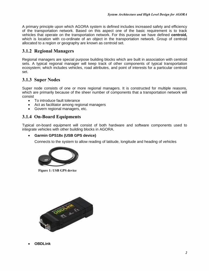
Garmin GPS18x (USB GPS device)
Connects to the system to allow reading of latitude, longitude and heading of vehicles
OBDLink
Figure 1: USB GPS device
System Architecture and High Level Design for AGORA
3
Connects to On Board Diagnostic (OBD) system of 1996 and newer vehicles allowing for collection of vehicle data such as RPMs, speed, etc.
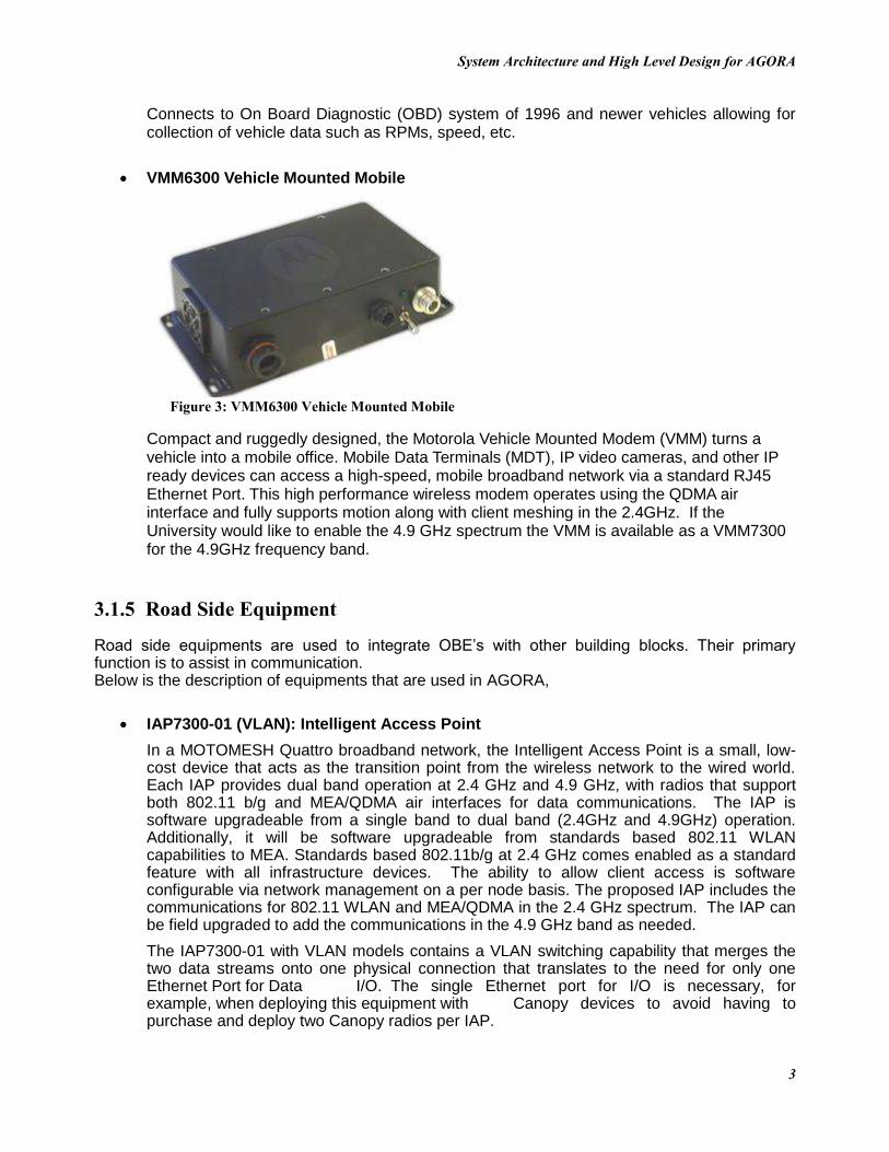
VMM6300 Vehicle Mounted Mobile
Compact and ruggedly designed, the Motorola Vehicle Mounted Modem (VMM) turns a vehicle into a mobile office. Mobile Data Terminals (MDT), IP video cameras, and other IP ready devices can access a high-speed, mobile broadband network via a standard RJ45 Ethernet Port. This high performance wireless modem operates using the QDMA air interface and fully supports motion along with client meshing in the 2.4GHz. If the University would like to enable the 4.9 GHz spectrum the VMM is available as a VMM7300 for the 4.9GHz frequency band.
3.1.5 Road Side Equipment
Road side equipments are used to integrate OBE’s with other building blocks. Their primary function is to assist in communication. Below is the description of equipments that are used in AGORA,
IAP7300-01 (VLAN): Intelligent Access Point
In a MOTOMESH Quattro broadband network, the Intelligent Access Point is a small, low-cost device that acts as the transition point from the wireless network to the wired world. Each IAP provides dual band operation at 2.4 GHz and 4.9 GHz, with radios that support both 802.11 b/g and MEA/QDMA air interfaces for data communications. The IAP is software upgradeable from a single band to dual band (2.4GHz and 4.9GHz) operation. Additionally, it will be software upgradeable from standards based 802.11 WLAN capabilities to MEA. Standards based 802.11b/g at 2.4 GHz comes enabled as a standard feature with all infrastructure devices. The ability to allow client access is software configurable via network management on a per node basis. The proposed IAP includes the communications for 802.11 WLAN and MEA/QDMA in the 2.4 GHz spectrum. The IAP can be field upgraded to add the communications in the 4.9 GHz band as needed.
The IAP7300-01 with VLAN models contains a VLAN switching capability that merges the two data streams onto one physical connection that translates to the need for only one Ethernet Port for Data I/O. The single Ethernet port for I/O is necessary, for example, when deploying this equipment with Canopy devices to avoid having to purchase and deploy two Canopy radios per IAP.
Figure 2: OBD Link
Figure 3: VMM6300 Vehicle Mounted Mobile

System Architecture and High Level Design for AGORA
4
MWR7300: Wireless Router
The Mobile Wireless Router (MWR) provides dual band (2.4 GHz and 4.9 GHz) broadband wireless data coverage for client access and wireless backhaul support for other wireless routers. This device also provides wireless network access to one or more IP devices via its built-in RJ45 Ethernet port. For the proposed MWR the ports are enabled with the included software licenses, which are enabled from the MiSC. Like the IAP, the MWR includes the communications for 802.11 WLAN and MEA/QDMA in the 2.4 GHz spectrum. The MWR can be field upgraded to add the communications in the 4.9 GHz band as needed.
MiSC: Mobile internet Switching Controller
The MiSC system includes hardware and software to provide routing, switching and network management functions. It also supplies the connection to the wired world. The proposed MiSC hardware has been provided to operate on the supplied Motorola supplied ML series laptop, core router and two LAN switches, one for the wireless equipment with its specific configuration and the other to support the connection of other application servers.
Figure 4:IAP7300-01 (VLAN), Intelligent Access Point
Figure 5: MWR7300, Wireless Router
System Architecture and High Level Design for AGORA
5
The MeshManager software resides on the Motorola supplied ML series laptop and provides all of the network management and gateway element functionality for the MOTOMESH Quattro network. As proposed the MeshManager application has been provided to support up to 50 MOTOMESH devices.
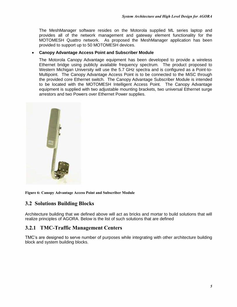
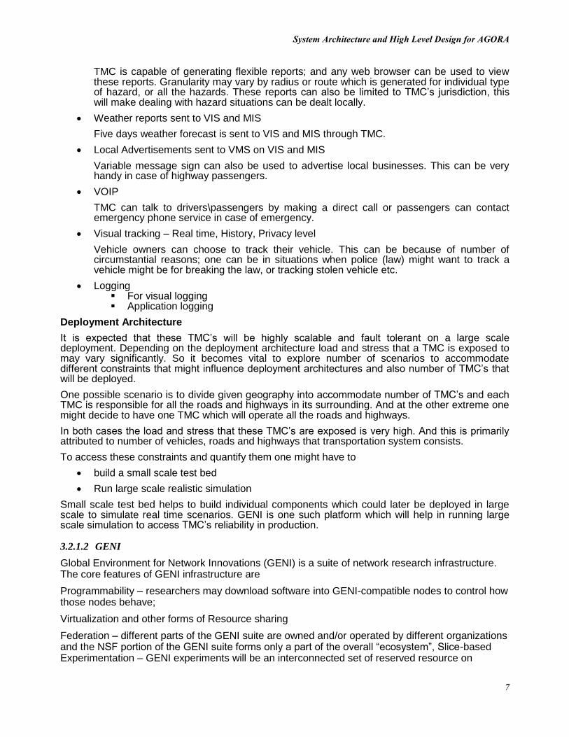
Canopy Advantage Access Point and Subscriber Module
The Motorola Canopy Advantage equipment has been developed to provide a wireless Ethernet bridge using publicly available frequency spectrum. The product proposed to Western Michigan University will use the 5.7 GHz spectra and is configured as a Point-to-Multipoint. The Canopy Advantage Access Point is to be connected to the MiSC through the provided core Ethernet switch. The Canopy Advantage Subscriber Module is intended to be located with the MOTOMESH Intelligent Access Point. The Canopy Advantage equipment is supplied with two adjustable mounting brackets, two universal Ethernet surge arrestors and two Powers over Ethernet Power supplies.
Figure 6: Canopy Advantage Access Point and Subscriber Module
3.2 Solutions Building Blocks
Architecture building that we defined above will act as bricks and mortar to build solutions that will realize principles of AGORA. Below is the list of such solutions that are defined
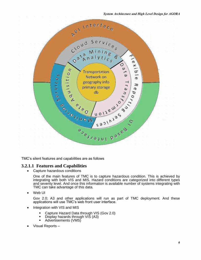
3.2.1 TMC-Traffic Management Centers
TMC’s are designed to serve number of purposes while integrating with other architecture building block and system building blocks.
System Architecture and High Level Design for AGORA
6
TMC’s silent features and capabilities are as follows
3.2.1.1 Features and Capabilities Capture hazardous conditions
One of the main features of TMC is to capture hazardous condition. This is achieved by integrating with both VIS and MIS. Hazard conditions are categorized into different types and severity level. And once this information is available number of systems integrating with TMC can take advantage of this data.
Web UI
Gov 2.0; A3 and other applications will run as part of TMC deployment. And these applications will use TMC’s web front user interface.
Integration with VIS and MIS
Capture Hazard Data through VIS (Gov 2.0) Display hazards through VIS (A3) Advertisements (VMS)
Visual Reports –
System Architecture and High Level Design for AGORA
7
TMC is capable of generating flexible reports; and any web browser can be used to view these reports. Granularity may vary by radius or route which is generated for individual type of hazard, or all the hazards. These reports can also be limited to TMC’s jurisdiction, this will make dealing with hazard situations can be dealt locally.
Weather reports sent to VIS and MIS
Five days weather forecast is sent to VIS and MIS through TMC.
Local Advertisements sent to VMS on VIS and MIS
Variable message sign can also be used to advertise local businesses. This can be very handy in case of highway passengers.
VOIP
TMC can talk to drivers\passengers by making a direct call or passengers can contact emergency phone service in case of emergency.
Visual tracking – Real time, History, Privacy level
Vehicle owners can choose to track their vehicle. This can be because of number of circumstantial reasons; one can be in situations when police (law) might want to track a vehicle might be for breaking the law, or tracking stolen vehicle etc.
Logging For visual logging Application logging
Deployment Architecture
It is expected that these TMC’s will be highly scalable and fault tolerant on a large scale deployment. Depending on the deployment architecture load and stress that a TMC is exposed to may vary significantly. So it becomes vital to explore number of scenarios to accommodate different constraints that might influence deployment architectures and also number of TMC’s that will be deployed.
One possible scenario is to divide given geography into accommodate number of TMC’s and each TMC is responsible for all the roads and highways in its surrounding. And at the other extreme one might decide to have one TMC which will operate all the roads and highways.
In both cases the load and stress that these TMC’s are exposed is very high. And this is primarily attributed to number of vehicles, roads and highways that transportation system consists.
To access these constraints and quantify them one might have to
build a small scale test bed
Run large scale realistic simulation
Small scale test bed helps to build individual components which could later be deployed in large scale to simulate real time scenarios. GENI is one such platform which will help in running large scale simulation to access TMC’s reliability in production.
3.2.1.2 GENI
Global Environment for Network Innovations (GENI) is a suite of network research infrastructure. The core features of GENI infrastructure are
Programmability – researchers may download software into GENI-compatible nodes to control how those nodes behave;
Virtualization and other forms of Resource sharing
Federation – different parts of the GENI suite are owned and/or operated by different organizations and the NSF portion of the GENI suite forms only a part of the overall “ecosystem”, Slice-based Experimentation – GENI experiments will be an interconnected set of reserved resource on

System Architecture and High Level Design for AGORA
8
platforms in diverse locations. One will be able to remotely discover, reserve, configure, program, debug, operate, manage, and teardown distributed systems established across parts of the GENI suite.
Because of these feature especially slice creation will enable us to deploy number of TMC’s and run number of scenarios. These slices can accommodate different aspects of TMC which are highlighted in the block diagram. Some of features of TMC that can be directly tested through GENI are interfaces
UI based interface API based interface
3.2.2 Gov 2.0
Gov 2.0 is a capability which is being developed to enable real time feedback to VIS regarding hazards. These hazards can be divided into number of categories. And public/vehicles can inform/gather this information either intelligently or it can be conveyed explicitly (manufactured).
3.2.2.1 Features and Capabilities
Detailed category list Category types
Natural (e.g. Icy condition, foggy) Artificial (e.g. Potholes, accidents etc)
Web interface In-vehicle interface Sync categories with TMC (idea is to keep VIS light weight) Methods to detect hazards
Intelligent – In vehicle Offline – manufactured (e.g. web, cell phone)
3.2.3 A3
A3 (Advisory alert application) is used in conjunction with Gov 2.0; A3 is the intelligence behind hazard awareness in VIS.
3.2.3.1 Features and Capabilities Detailed category list Category types
Natural (e.g. Icy condition, foggy) Artificial (e.g. Potholes, accidents etc)
Web interface In-vehicle interface Sync categories with TMC (idea is to keep VIS light weight) Methods to detect hazards
Intelligent – In vehicle Offline – manufactured (e.g. web, cell phone)
3.2.4 VIS
Vehicle Integrated System is tailored solution that will be integrated in all the vehicles that operate in the given transportation network. This solution will also be custom tailored for different type of vehicles that operate on the transportation network.

System Architecture and High Level Design for AGORA
9
3.2.4.1 Features and Capabilities Coarse context visualization and detailed context visualization Road side signs Traffic light timing information Icy road conditions Foggy conditions School-bus, emergency vehicle, road work, Hazardous road conditions Unsafe proximity to vehicles Fuel consumption Trip time Carbon footprint VoIP Toll application Parking application Gas prices around current GPS location Weather summary
4. Architecture Vision
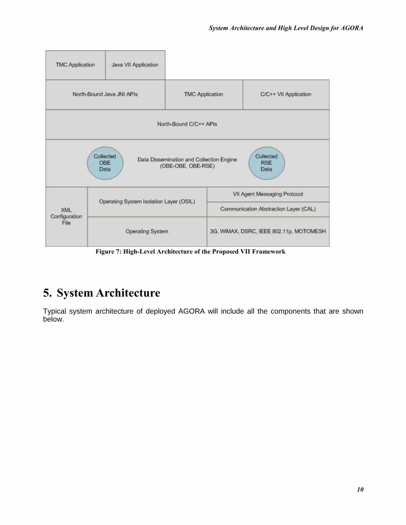
The high level architecture of the proposed AGORA framework is as shown below. It should be noticed that the framework hides the complexities associated with the data exchange process (between OBE’s and between OBE’s and RSE’s) from application developers. This enables developers to focus on utilizing the collected data from neighboring vehicles and road-side equipment to build advanced AGORA application.
System Architecture and High Level Design for AGORA
10
5. System Architecture
Typical system architecture of deployed AGORA will include all the components that are shown below.
Figure 7: High-Level Architecture of the Proposed VII Framework

System Architecture and High Level Design for AGORA
11
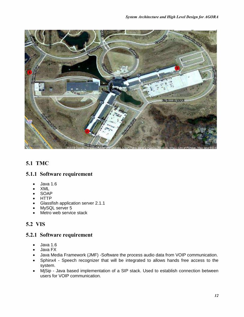
This system architecture at Western Michigan University provides a MOTOMESH Quattro system that is similar to the equipment that has been deployed around the Rack Financial Center in Novi, Michigan. This includes equipment for one Mobile Internet Switching Controller (MiSC), one MOTOMESH Quattro Intelligent Access Point (IAP), two MOTOMESH Quattro Mobile Wireless Routers (MWR) and three MOTOMESH 6300 Vehicle Mounted Modems (VMM). Also included with the MOTOMESH equipment is one Canopy Advantage Access Point and Subscriber Module to be used to extend the Ethernet link between the Mobile Internet Switching Controller and the MOTOMESH Intelligent Access Point. Locations 1, 2, and 3 shown in the image below denote the future placement of the IAP and (2) MWR. The device at location 1 will be powered by a wind turbine.
Figure 8: Typical System
System Architecture and High Level Design for AGORA
12
5.1 TMC
5.1.1 Software requirement
Java 1.6 XML SOAP HTTP Glassfish application server 2.1.1 MySQL server 5 Metro web service stack
5.2 VIS
5.2.1 Software requirement
Java 1.6 Java FX
Java Media Framework (JMF) -Software the process audio data from VOIP communication.
Sphinx4 - Speech recognizer that will be integrated to allows hands free access to the system.
MjSip - Java based implementation of a SIP stack. Used to establish connection between users for VOIP communication.

System Architecture and High Level Design for AGORA
13
5.3 Gov 2.0
5.3.1 Software requirement
Java 1.6 Java FX JAX-WS VIS
5.4 A3
5.4.1 Software requirement
Java 1.6 Java FX JAX-WS VIS
6. Tools and Utilities
As part of the system design and construction number of tools and utilities will be developed to facilitate in the design. Some of these have been mentioned below
6.1 Road Sign Capture Tool
This tool is used to capture road signs such as speed limits, pedestrian crossing, stop sign etc. For each of the signs corresponding metadata is generated and stored in configuration store, which is later communicated in the VIS and other systems.
Appendix A: Glossary
MDOT – Michigan Department of Transportation OBE – On-Board Equipment RSE – Road-Side Equipment TMC – Traffic Management Centers A3– Advisory Alert Application LSA – Life Safety Application VIS – Vehicle Integrated Software