System and Software Architecture Description (SSAD ... · System and Software Architecture...
31
System and Software Architecture Description (SSAD) Version 3.0 Software System Architecture Document (SSAD) Healthy Kids Zone Survey App Team 14 Name Primary Role Contact Email Jessie Kim Client [email protected] Joseph Martinez Client [email protected] Malcolm Carson Client [email protected] Yang Wang Project Manager [email protected] Chad Honkofsky IIV&V/QFP [email protected] Xu Zhang Builder (Front-end Designer) [email protected] Chenglu Wang Tester [email protected] Junjun Ji Builder (Mobile Designer) [email protected] Ye Tao Builder (Back-end Designer) [email protected]
Transcript of System and Software Architecture Description (SSAD ... · System and Software Architecture...

System and Software Architecture Description (SSAD) Version 3.0
Software System Architecture Document (SSAD)
Healthy Kids Zone Survey App
Team 14
Name Primary Role Contact Email Jessie Kim Client [email protected] Joseph Martinez Client [email protected] Malcolm Carson Client [email protected] Yang Wang Project Manager [email protected] Chad Honkofsky IIV&V/QFP [email protected] Xu Zhang Builder (Front-end
Designer) [email protected]
Chenglu Wang Tester [email protected] Junjun Ji Builder (Mobile
Designer) [email protected]
Ye Tao Builder (Back-end Designer)

System and Software Architecture Description (SSAD) Version 3.0
ii
Version History Date Author Version Changes made Rationale
10/16/2013 Qianu Liao 1.0 • System Context Diagram • Consolidated System Context
Diagram to match OCD
10/17/2013 Qianyu Liao 1.1 • System Users Behavior • Consolidated System Users Behavior
to match OCD
10/17/2013 Qianyu Liao 1.2 • System Use Case • Consolidated use cases to match
OCD
10/18/2013 Qianyu Liao 1.3 • System Use Case • Consolidated use cases to match
OCD
10/18/2013 Qianyu Liao 1.4 • System Use Case • Consolidated use cases to match
OCD
10/18/2013 Qianyu Liao 1.5 • System physical architecture • Consolidated use cases to match the
clients requirement
10/19/2013 Qianyu Liao 1.6 • Add Survey Monkey to System Context
Diagram • Added System Context Diagram to
match Client Requirement
10/20/2013 Qianyu Liao 2.1 • Reduce Use Case • Reduced use cases to match ARB
Review
11/20/2013 Qianyu Liao 2.2 • Modify use case, physical architecture • Modified use cases and physical
architecture to match DCR Review
11/27/2013 Qianyu Liao 2.3 • Rewrite the SSAD
• Rewrite the SSAD document to match the DCR Review and prepare for the development phase
11/28/2013 Qianyu Liao 2.4 • Modify Artifact and Information
Diagram • To satisfy the requirement
12/09/2013 Qianyu Liao 2.5 • Add the NDI/NCS evaluation part to
SSAD • To complete the whole SSAD
02/09/2014 Ye Tao 3.0 • Update Artifact and Information Diagram and System Behavior
• To comply with the system requirement
02/17/2014 Ye Tao 3.1 • Update Artifact and Information Diagram and System Behavior
• To comply with the system requirement

System and Software Architecture Description (SSAD) Version 3.0
iii
Table of Contents SOFTWARE SYSTEM ARCHITECTURE DOCUMENT (SSAD) ....................................................................................... I VERSION HISTORY ................................................................................................................................................ II TABLE OF CONTENTS ........................................................................................................................................... III TABLE OF TABLES ................................................................................................................................................ IV TABLE OF FIGURES ............................................................................................................................................... V
1. Introduction ................................................................................................................................................. 1 1.1 Purpose of the SSAD ............................................................................................................................................... 1 1.2 Status of the SSAD ................................................................................................................................................... 1
2. System Analysis ............................................................................................................................................ 2 2.1 System Analysis Overview ....................................................................................................................................... 2
2.1.1 System Context ............................................................................................................................................... 2 2.1.2 Artifacts and information ................................................................................................................................ 3 2.1.3 Behavior .......................................................................................................................................................... 5
3. NDI/NCS Interoperability Analysis ............................................................................................................. 17 3.1 Introduction .......................................................................................................................................................... 17
3.1.1 COTS / GOTS / ROTS / Open Source / NCS .................................................................................................... 17 3.1.2 NDI/NCS Evaluation ...................................................................................................................................... 17
3.2 System Structure ................................................................................................................................................... 18 4. Class Design ............................................................................................................................................... 22
4.1 Interface Classes ................................................................................................................................................... 22 4.2 Process Realization ................................................................................................................................................ 24
4.2.1 Render Survey Import Page .......................................................................................................................... 24 5. Architectural Styles, Patterns and Framework .......................................................................................... 26

System and Software Architecture Description (SSAD) Version 3.0
iv
Table of Tables Table 1: Context Summary ............................................................................................................................ 3
Table 2: Artifact and Information Summary ................................................................................................. 4
Table 3: Use Case Description ..................................................................................................................... 5
Table 4: Use Case Description ..................................................................................................................... 6
Table 5: Use Case Description ..................................................................................................................... 6
Table 6: Use Case Description ..................................................................................................................... 7
Table 7: Use Case Description ..................................................................................................................... 8
Table 8: Use Case Description ..................................................................................................................... 8
Table 9: Use Case Description ..................................................................................................................... 9
Table 10: Use Case Description ................................................................................................................... 9
Table 11: Use Case Description ................................................................................................................. 10
Table 12: Use Case Description ................................................................................................................. 10
Table 13: Use Case Description ................................................................................................................. 11
Table 14: Use Case Description ................................................................................................................. 11
Table 15: Use Case Description ................................................................................................................. 11
Table 16: Use Case Description ................................................................................................................. 12
Table 17: Use Case Description ................................................................................................................. 13
Table 18: Use Case Description ................................................................................................................. 14
Table 19: Use Case Description ................................................................................................................. 14
Table 20: Use Case Description ................................................................................................................. 15
Table 21: Use Case Description ................................................................................................................. 15
Table 22: Use Case Description ................................................................................................................. 15
Table 23: Use Case Description ................................................................................................................. 16
Table 24: NDI/NCS Product List ................................................................................................................ 17
Table 25: Comparison of hybrid mobile app platform ............................................................................... 17
Table 26: Comparison of survey application .............................................................................................. 18
Table 27: Hardware Component Description ............................................................................................. 19
Table 28: Software Component Description ............................................................................................... 20
Table 29: Design Class Description ........................................................................................................... 22
Table 30: Architectural Styles, Patterns, and Frameworks ........................................................................ 26

System and Software Architecture Description (SSAD) Version 3.0
v
Table of Figures Figure 1: System Context Diagram ................................................................................................ 2 Figure 2: Artifact and Information Diagram .................................................................................. 4
Figure 3: Process Diagram ............................................................................................................ 5 Figure 4: Hardware component Diagram .................................................................................... 19
Figure 5: Software component Diagram ...................................................................................... 20 Figure 6: Deployment Diagram .................................................................................................... 21
Figure 7: Design Class Diagram .................................................................................................. 22 Figure 8: Render Survey Import Page Class Diagram ................................................................ 23
Figure 9: Survey Import Class Diagram ...................................................................................... 24 Figure 10: Render Survey Import Page Sequence Diagram ........................................................ 25
Figure 11: Survey Import Sequence Diagram .............................................................................. 25
1
1. Introduction
1.1 Purpose of the SSAD The purpose of the SSAD is to document the results of the object-oriented analysis and design (OOA&D) of the website being developed. The SSAD is used by the developer as reference to the system architecture. The website being developed should be faithful to the architecture specified in the SSAD. Furthermore, the SSAD is used by the maintainer and clients to help understand the structure of the system once the proposed website is delivered.
1.2 Status of the SSAD The current version of the SSAD is 3.0 and it is at the end of the Rebaselined Foundation phase. At this point, all sections of the document are filled out with system context diagram, system behavior diagram, use case diagram, component diagram, deployment diagram, class diagram and sequence diagram. Team is actively exploring NDI, NCS and the selected architecture (3-tier architecture) and prototyping the system using it. Thus this document reflects current understanding of the developing system and the high risk features, and is an agreement with current prototype.

2
2. System Analysis
2.1 System Analysis Overview The primary purpose of Healthy Kids Zone Survey App is to map and assess physical assets and detriments to health as part of our initiative to reduce rates of obesity and hypertension in South Los Angeles. The Healthy Kids Zone Survey App System allows administrator to import the survey from survey monkey application (the administrator should create the survey on the survey monkey first), configure the connection between school, path and survey, and then the administrator could export the survey results. The Healthy Kids Zone Survey App System allows user take survey on their mobile app easily. Figure 1 is the System Context Diagram. Table 1 is the diagram summary.
2.1.1 System Context
Figure 1: System Context Diagram

3
Table 1: Context Summary
Actor Description Responsibilities Healthy Kids Zone Survey System
The new system our team will build
• The website system will be used by administrator to import survey, configure the connection between schools, paths and surveys, and export survey results
• The mobile app system will be used by uses to take survey easily
Administrator People who use the Healthy Kids Zone website system and manage the system.
• Import survey from survey monkey
• Configure the connection between school, path and survey
• Export the survey results
Users People who use the Healthy Kids Zone survey app to take survey
• Take survey
Survey monkey An application that the administrator could create survey An API that the website system could retrieve the surveys list and details
• Create survey • Retrieve survey details
Google map An API that the administrator could draw the path coordinates An API that the users could add markers and comments
• Draw path coordinates • Add markers and comments
2.1.2 Artifacts and information Figure 2 illustrates the data structure of our system.

4
Figure 2: Artifact and Information Diagram
Table 2: Artifact and Information Summary
Artifact Purpose ATF-1: Schools School information the administrator adds through the website ATF-2: Paths Path coordinates the administrator selects on the google map ATF-3: Surveys General information about survey which is retrieved from Survey
Monkey API ATF-4: Associates Based on our requirements, one survey can be used in many paths;
one path can contain many surveys. They are many-to-many relationship, so we generate a new table to store the relations.
ATF-5: Questions Question information in the survey which is retrieved from Survey Monkey
ATF-6: Options Option information of multiple choice question in the survey which is retrieved from survey monkey
ATF-7: Answers Answer information sent from Mobile application. ATF-8: CommentsAnswers Long text-based answer of comments question. ATF-9: Markers To store markers that our app system provide ATF-10: BreakingPoints To describe path curve for mobile path display ATF-11: Image To store images binding to survey questions

5
2.1.3 Behavior Figure 3 illustrates the behaviors of users and administrators.
Figure 3: Process Diagram
2.1.3.1 Administrator use cases
Table 3: Use Case Description
Identifier UC-1: Main page Pre-conditions Administrator is logged into the system. Post-conditions Administrator is logged out of the system. Typical Course of Action
Actor Input System Response 1 Administrator clicks logout
button
6
2 System logs user out and redirects him to HKZ login page
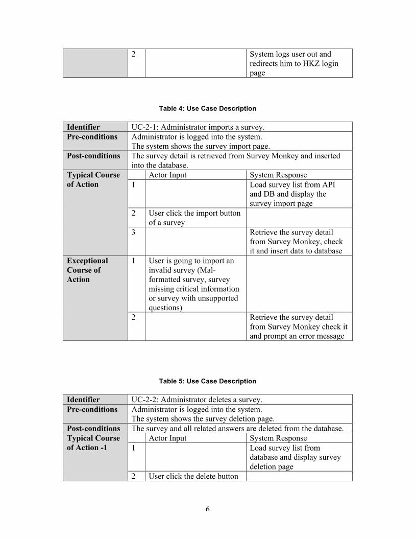
Table 4: Use Case Description
Identifier UC-2-1: Administrator imports a survey. Pre-conditions Administrator is logged into the system.
The system shows the survey import page. Post-conditions The survey detail is retrieved from Survey Monkey and inserted
into the database. Typical Course of Action
Actor Input System Response 1 Load survey list from API
and DB and display the survey import page
2 User click the import button of a survey
3 Retrieve the survey detail from Survey Monkey, check it and insert data to database
Exceptional Course of Action
1 User is going to import an invalid survey (Mal-formatted survey, survey missing critical information or survey with unsupported questions)
2 Retrieve the survey detail from Survey Monkey check it and prompt an error message
Table 5: Use Case Description
Identifier UC-2-2: Administrator deletes a survey. Pre-conditions Administrator is logged into the system.
The system shows the survey deletion page. Post-conditions The survey and all related answers are deleted from the database. Typical Course of Action -1
Actor Input System Response 1 Load survey list from
database and display survey deletion page
2 User click the delete button

7
of a survey 3 Check the database whether
there are answers under this survey. If so, prompt a confirm message to the administrator that it is an irreversible operation
4 User click confirm button 5 Delete the survey from
database Typical Course of Action -2
4 User click cancel button 5 Return to the survey deletion
page Exceptional Course of Action
1 If there is no answer under the survey to be deleted, delete the survey without confirmation
Table 6: Use Case Description
Identifier UC-3-1: Administrator adds a school. Pre-conditions Administrator is logged into the system.
The system shows the school adding page. Post-conditions A school (including school name, address and location
information) is added and inserted into the database. Typical Course of Action
Actor Input System Response 1 Display the school adding
page 2 User types in the school
name and address and then click add button
3 Retrieve the school information from the database. Check if there is a school with the same name and address. If not, insert the school name and address into the database.
Exceptional Course of Action
1 If there is a school with the same name and address in the database, prompt an alert that the school is already in the database.

8
Table 7: Use Case Description
Identifier UC-3-2: Administrator deletes a school. Pre-conditions Administrator is logged into the system.
The system shows the school deletion page. Post-conditions The school and all related answers are deleted from the database. Typical Course of Action
Actor Input System Response 1 Load school list from the
database and display the school deletion page
2 User clicks the delete button of a school
3 Check the database whether there are answers under this school. If so, prompt a confirm message to the administrator that it is an irreversible operation
4 User clicks confirm button 5 Delete the school from the
database Typical Course of Action -2
4 User click cancel button 5 Return to the school deletion
page Exceptional Course of Action
1 If there is no answer under the school to be deleted, delete the school without confirmation
Table 8: Use Case Description
Identifier UC-3-3: Administrator modifies a school name. Pre-conditions Administrator is logged into the system.
The system shows the school modify page. Post-conditions The school name is modified in the database. Typical Course of Action
Actor Input System Response 1 Load school list from the
database and display the school modify list including school name and address
2 User select a school and types in the school name and then click add button
3 Update the school name in the database

9
Table 9: Use Case Description
Identifier UC-4-1: Administrator adds a path. Pre-conditions Administrator is logged into the system.
The system shows the path adding page. Post-conditions The selected path is inserted into the database. Typical Course of Action
Actor Input System Response 1 Load school list from the
database and display the school list, a text box for path name and a map
2 Select one of the schools 3 Pin location of the school in
the map 4 Drop a starting point and an
ending point in the map, type in path name and click confirm
5 Insert the information of path name and location to database
Table 10: Use Case Description
Identifier UC-4-2: Administrator deletes a path. Pre-conditions Administrator is logged into the system.
The system shows the path deletion page. Post-conditions The selected path is deleted from the database. Typical Course of Action
Actor Input System Response 1 Load school list from the
database and display the path deletion page
2 Selects a school from the list.
3 Load path list from the database and display path list related to the selected school.
4 Clicks the delete button of a path
5 Check the database whether there are answers under this path. If so, prompt a confirm message to the administrator that it is an irreversible

10
operation 6 Clicks confirm button 7 Delete the path and answers
related to the path from the database.
Exceptional Course of Action
1 If there is no answer under the path to be deleted, delete the path without confirmation
Table 11: Use Case Description
Identifier UC-5-1: Administrator associates a path with a survey. Pre-conditions Administrator is logged into the system.
The system shows the association page. Post-conditions The selected path is associated with the selected path and the
association is inserted into the database. Typical Course of Action
Actor Input System Response 1 Load survey list and school
list from the database and display the association page
2 Select survey name and school name from the lists.
3 Load path list from the database
4 Select path name from the list and click associate button.
5 Check if there is already an association between the path and the survey. If not, insert an association to the database
Table 12: Use Case Description
Identifier UC-5-2: Administrator unlinks an association. Pre-conditions Administrator is logged into the system.
The system shows the association page. Post-conditions The association is deleted from the database. Typical Course of Action
Actor Input System Response 1 Load association list from the
database and display the association deletion page
2 Select an association from
11
the list and click unlink 3 Delete the association from
the database
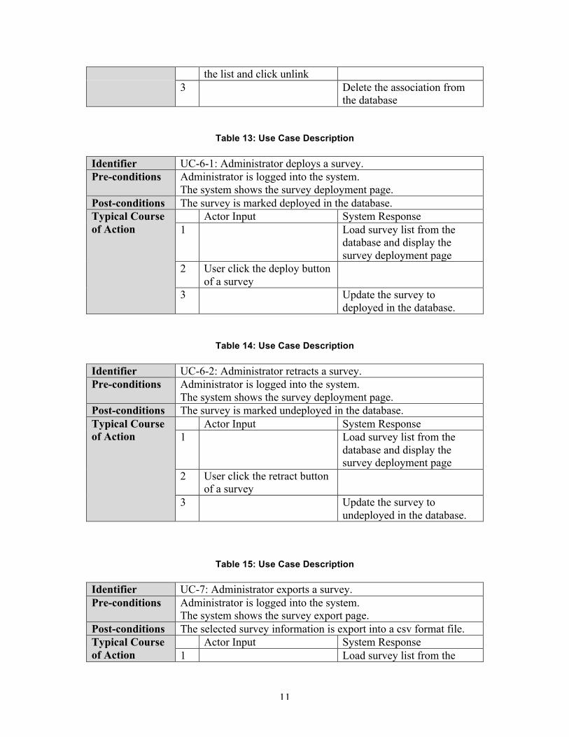
Table 13: Use Case Description
Identifier UC-6-1: Administrator deploys a survey. Pre-conditions Administrator is logged into the system.
The system shows the survey deployment page. Post-conditions The survey is marked deployed in the database. Typical Course of Action
Actor Input System Response 1 Load survey list from the
database and display the survey deployment page
2 User click the deploy button of a survey
3 Update the survey to deployed in the database.
Table 14: Use Case Description
Identifier UC-6-2: Administrator retracts a survey. Pre-conditions Administrator is logged into the system.
The system shows the survey deployment page. Post-conditions The survey is marked undeployed in the database. Typical Course of Action
Actor Input System Response 1 Load survey list from the
database and display the survey deployment page
2 User click the retract button of a survey
3 Update the survey to undeployed in the database.
Table 15: Use Case Description
Identifier UC-7: Administrator exports a survey. Pre-conditions Administrator is logged into the system.
The system shows the survey export page. Post-conditions The selected survey information is export into a csv format file. Typical Course of Action
Actor Input System Response 1 Load survey list from the

12
database and display the survey export page
2 User click the export button of a survey
3 Retrieve the survey detail from the database. Construct a survey report containing all the answers grouped by location information in csv format
Exceptional Course of Action
1 1 stands for yes, and 0 stands for no. Missing information should be marked as -9 in the report
2.1.3.2 Mobile user use cases
Table 16: Use Case Description
Identifier UC-8: User starts a new survey. Pre-conditions The application shows the application homepage. Post-conditions Information of the selected survey is retrieved from the database
and system jumps into a question category page of the selected survey.
Typical Course of Action
Actor Input System Response 1 User click the new survey
button
2 Send request and retrieve school, path and survey list from the server and display a school list
3 Select a school in the list 4 Display a path list of the
selected school 5 Select a path in the list 6 Display a survey list with
surveys associated with the selected path
7 Select a survey in the list 8 Send request and retrieve the
selected survey from the server and display a category page with a question list

13
Table 17: Use Case Description
Identifier UC-9-1: User answers survey questions. Pre-conditions The application shows the question page. Post-conditions The answer to the question is stored in temporary storage on the
phone, waiting to be submitted. Typical Course of Action -1
Actor Input System Response 1 Displays a question with
multiple choice (single answer)
2 Clicks one of the answers. 3 The answer appears chosen.
Updates the answer in the temporary storage file.
Typical Course of Action -2
1 Displays a question with multiple choice (multiple answer)
2 Clicks a collection of the answers
3 The answers are chosen. Updates the answer in the temporary storage file
Typical Course of Action -3
1 Displays a comment question with an edit box
2 Types in comments in the edit box
3 Updates the answer in the temporary storage file
Typical Course of Action -4
1 Displays a tally question with a number, a plus and a minus mark
2 Clicks on plus or minus 3 Updates the answer in the
temporary storage file Exceptional Course of Action -1
1 Click the function bar 2 Display a function menu
including show map, save, quit without saving and submit
3 Click one of these choices 4 Jump to execute
corresponding feature

14
Exceptional Course of Action -2
1 Click category button 2 Jump to question category list
Table 18: Use Case Description
Identifier UC-9-2: User navigates in the category list. Pre-conditions The system shows a question category list of the selected survey. Post-conditions The system jumps into the selected question page. Typical Course of Action
Actor Input System Response 1 Display a question category
list 2 Click a question type
(Block/Tally/Other)
3 Display a question list of selected question type
4 Click a question in the list 5 Jump into question page of
the selected question
Table 19: Use Case Description
Identifier UC-10: User adds a marker. Pre-conditions The system shows a map of the selected path. Post-conditions Marker location and comments are inserted into database. Typical Course of Action
Actor Input System Response 1 Display a map of the selected
path 2 Right click on the map to
create a marker
3 Display a comment box over the map
4 Type in comments with respect to the marker (For example, report some hazard)
5 Send the comment text to the server and the server insert data into the database
Exceptional Course of Action
1 User types in comment over 500 characters.
2 Display an error message that character number is over-limited

15
Table 20: Use Case Description
Identifier UC-11-1: User saves a survey to the mobile device. Pre-conditions The system shows a function menu in question or category page. Post-conditions Answers to the ongoing survey are stored in the mobile device. Typical Course of Action
Actor Input System Response 1 User clicks the save button
in function menu
2 Store the temporary file to app storage.
Exceptional Course of Action
1 The mobile device is out of available space.
2 Display an error message that the device does not have enough space.
Table 21: Use Case Description
Identifier UC-11-2: User loads an existing survey from the mobile device. Pre-conditions The system shows the application homepage. Post-conditions Survey answers and questions are retrieved from local storage of
the mobile device and the system shows a question page. Typical Course of Action
Actor Input System Response 1 User clicks the load survey
button in homepage
2 Load and continue a survey from record file in app storage. Jump to question category page.
Exceptional Course of Action
1 There is no existing survey saved in the device.
2 Display an error message that no saved survey is found.
Table 22: Use Case Description
Identifier UC-12-1: User submits a survey. Pre-conditions The system shows a function menu in question or category page.

16
Post-conditions The survey answers are submitted to the server and inserted into the database.
Typical Course of Action
Actor Input System Response 1 User clicks the submit
button in function menu
2 Check whether all the questions are answered. If so, send the answer to the server. The server inserts the answer into the database.
Exceptional Course of Action
1 If some of the answers are unanswered, prompt a message that finish the survey first and then try again.
Table 23: Use Case Description
Identifier UC-12-2: User relinquishes a survey. Pre-conditions The system shows a function menu in question or category page. Post-conditions The survey answers are deleted and the system returns to the
application homepage. Typical Course of Action
Actor Input System Response 1 User clicks the quit without
saving button in function menu
2 Display a confirmation that it will delete all the answers and quit.
3 Click confirm button. 4 Delete the temporary file and
return to the homepage.

17
3. NDI/NCS Interoperability Analysis
3.1 Introduction In this project, Healthy Kids Zone Survey App will retrieve the survey detail info from Survey Monkey API and use Google Map to define the path for the survey.
3.1.1 COTS / GOTS / ROTS / Open Source / NCS
Table 24: NDI/NCS Product List
NDI/NCS Products Purposes Survey Monkey Help administrator to create survey
Retrieve survey detail info from Survey Monkey API
PhoneGap / JQuery Mobile A framework to develop a hybrid mobile app
Google Map Administrator can define the path coordinates on the map User can add markers and comments on the map
MySQL To store survey data Apache web server Such as, provide different languages
compiling, font-end and back-end communication, data transmission service
3.1.2 NDI/NCS Evaluation
Table 25: Comparison of hybrid mobile app platform
NDI/NCS Pros Cons Titanium 1. Rapid prototyping;
2. Native UI; 3. native app performance, we did the tab
transition prototype comparison with other platform to prove that;
4. accessible to device features, we did the taking picture prototype to prove it;
1. Only compatible with Android and IOS and BlackBerry. However, our clients only require us to develop the mobile app based on the android platform
PhoneGap 1. Rapid testing and deployment; 2. Access basic native functionality; 3. Relatively flat learning curve.
1. Poor performance especially in the automation, transition and tabs change. , we
18
proved it by prototyping. Basically, it need 0.5 minute more than Titanium);
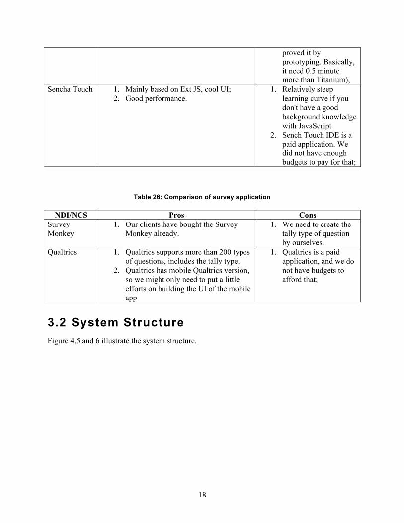
Sencha Touch 1. Mainly based on Ext JS, cool UI; 2. Good performance.
1. Relatively steep learning curve if you don't have a good background knowledge with JavaScript
2. Sench Touch IDE is a paid application. We did not have enough budgets to pay for that;
Table 26: Comparison of survey application
NDI/NCS Pros Cons Survey Monkey
1. Our clients have bought the Survey Monkey already.
1. We need to create the tally type of question by ourselves.
Qualtrics 1. Qualtrics supports more than 200 types of questions, includes the tally type.
2. Qualtrics has mobile Qualtrics version, so we might only need to put a little efforts on building the UI of the mobile app
1. Qualtrics is a paid application, and we do not have budgets to afford that;
3.2 System Structure Figure 4,5 and 6 illustrate the system structure.

19
Figure 4: Hardware component Diagram
Table 27: Hardware Component Description
Hardware Component Description Networked Computer A computer that is connected to other networked computers
through the internet. In our system, every computer will be networked in this manner.
Application Server A networked computer which provides applications to workstations. In our system, this will be the server our software will be deployed on.
Workstation A networked computer which is used to access services on the internet. In our system, this will be computers used by people at home or in an office to interact with the timeline application server.
Networked Smartphone A mobile phone built on a mobile operating system, with more advanced computing capability and connectivity than a feature phone
Networked Device The device such as, router

20
Figure 5: Software component Diagram
Table 28: Software Component Description
Software Component Description Website User Interface The HTML and php pages and forms that users of the
system interact with directly Survey Import Manager The part of the system that used to retrieve survey detail
from survey monkey and then import survey Survey Configuration Manager
Manage the school and paths, such as, add, delete, modify, create, and associate the connection between school, path and surveys
Database Manager Control the database connection Survey Export Manager Export the survey results by csv file format Survey Completion Manager
Loading schools, paths, surveys from database and then insert the survey results to database, help users to complete the survey.
Mobile App System User Interface
The HTML and JS pages and forms that users of the system interact with directly
Apache Such as, provide different languages compiling, font-end and back-end communication, data transmission service

21
Figure 6: Deployment Diagram

22
4. Class Design
4.1 Interface Classes
Figure 7: Design Class Diagram
Table 29: Design Class Description
Class Type Description Home page Boundary Main page of the website system Login page Boundary Page with a login form Survey creation page Boundary Page that redirect user to survey monkey.com Survey import page Boundary Page that import survey School and path management page
Boundary Page that administrator could add/delete/modify school and path
Associate connection page Boundary Page that administrator could associate the connection between school, path and survey
Survey export page Boundary Page that administrator could export survey results School selection screen Boundary Screen that user can select a school Path selection screen Boundary Screen that user can select a path Survey selection screen Boundary Screen that user can select a survey Question category screen Boundary Screen that user can view all the question type Block 1-n question screen Boundary Screen that user answer the question for each

23
block Tally question screen Boundary Screen that user answer the question of tally type Home screen Boundary Main page of the mobile app system Google map screen Boundary Screen that user can see the path of the survey and
add marker/comment to the map Survey completion screen Boundary Screen that user submit the survey successfully
Figure 8: Render Survey Import Page Class Diagram
24
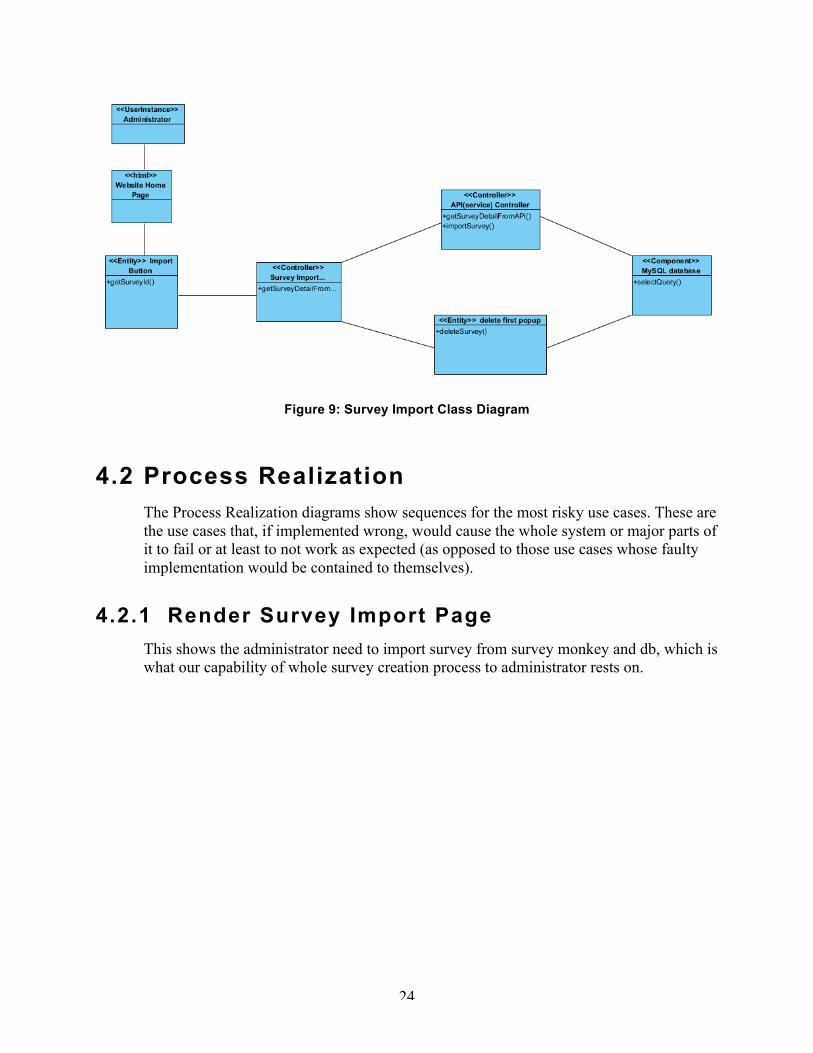
Figure 9: Survey Import Class Diagram
4.2 Process Realization The Process Realization diagrams show sequences for the most risky use cases. These are the use cases that, if implemented wrong, would cause the whole system or major parts of it to fail or at least to not work as expected (as opposed to those use cases whose faulty implementation would be contained to themselves).
4.2.1 Render Survey Import Page This shows the administrator need to import survey from survey monkey and db, which is what our capability of whole survey creation process to administrator rests on.

25
Figure 10: Render Survey Import Page Sequence Diagram
Figure 11: Survey Import Sequence Diagram

26
5. Architectural Styles, Patterns and
Framework
Table 30: Architectural Styles, Patterns, and Frameworks
Name Description Benefits, Costs, and Limitations Three-tier Architecture
Three-tier architecture is an architectural style and a design pattern that separates the presentation of data, business logic and the data itself into tiers that, in the case of our system, reside on two different systems and are managed with three different applications:
• All data is presented within web browsers on networked machines that will in most cases be offsite.
• The business logic platform will be Apache running on Linux Cent OS 5.9
• The data will be managed using a MySQL database running on Linux CentOS 5.9 on the same virtual machine as Apache (this is based on the setup of the physical system)
Benefits: • Individual tiers can be
modified independently from the rest of the system without breaking it (less coupled than a monolithic architecture)
• Enforces separation of data, business logic and presentation on the developers, thereby making them create code that is more easily maintained because its functionality is more easily understood due to its impact being more localized within the system.
Cost: • There is no specific cost
required. • Limitations: Potential limited
speed losses when data which is transferred between the browser and the database and vice versa has to pass through the separate business layer and has to be replicated in the database and the servlet container