System 800xA 5.1 RevD Release Notes New …...Power and productivity for a better worldTM System...
342
Power and productivity for a better world TM System 800xA Release Notes New Functions and Known Problems System Version 5.1 Rev D
Transcript of System 800xA 5.1 RevD Release Notes New …...Power and productivity for a better worldTM System...

Power and productivity
for a better worldTM
System 800xARelease NotesNew Functions and Known Problems
System Version 5.1 Rev D

System 800xARelease Notes
New Functions and Known Problems
System Version 5.1 Rev D
NOTICEThis document contains information about one or more ABB products and may include adescription of or a reference to one or more standards that may be generally relevant tothe ABB products. The presence of any such description of a standard or reference to astandard is not a representation that all of the ABB products referenced in this documentsupport all of the features of the described or referenced standard. In order to determinethe specific features supported by a particular ABB product, the reader should consult theproduct specifications for the particular ABB product.
ABB may have one or more patents or pending patent applications protecting the intel-lectual property in the ABB products described in this document.
The information in this document is subject to change without notice and should not beconstrued as a commitment by ABB. ABB assumes no responsibility for any errors thatmay appear in this document.
In no event shall ABB be liable for direct, indirect, special, incidental or consequentialdamages of any nature or kind arising from the use of this document, nor shall ABB beliable for incidental or consequential damages arising from use of any software or hard-ware described in this document.
This document and parts thereof must not be reproduced or copied without written per-mission from ABB, and the contents thereof must not be imparted to a third party nor usedfor any unauthorized purpose.
The software or hardware described in this document is furnished under a license andmay be used, copied, or disclosed only in accordance with the terms of such license. Thisproduct meets the requirements specified in EMC Directive 2004/108/EC and in Low Volt-age Directive 2006/95/EC.
TRADEMARKSAll rights to copyrights, registered trademarks, and trademarks reside with their respec-tive owners.
Copyright © 2003-2016 by ABB. All rights reserved.
Release: June 2016Document number: 2PAA111287-510 B

2PAA111287-510 B 5
Table of Contents
About This Release NoteGeneral ............................................................................................................................15
How Feature Packs Work in System 800xA?..................................................................15
Release Note Conventions ...............................................................................................16
Warning, Caution, Information, and Tip Icons................................................................16
Terminology.....................................................................................................................17
Released User Manuals and Release Notes.....................................................................17
Section 1 - Release NotesIntroduction .....................................................................................................................19
Products Participating in This Revision ..........................................................................20
Release Notes Safety Notices .......................................................................................20
Related Documentation ...................................................................................................21
Additional References ..........................................................................................22
Product Support ...............................................................................................................22
Section 2 - Functionality ChangesIntroduction .....................................................................................................................23
Third Party Software in 800xA 5.1 .................................................................................23
Microsoft Office 2007 and 2010 ..........................................................................23
SQL Sever 2008 SP3............................................................................................24
Oracle Updates .....................................................................................................24
Crystal Reports 2008............................................................................................24
Internet Explorer 9 ...............................................................................................25
VMware ESX (i) ..................................................................................................25
Internet Protocol Security (IPsec) Configuration Tool ....................................................25

Table of Contents
6 2PAA111287-510 B
Licensing and Automation Sentinel ................................................................................ 25
System Installer (Automated Installation) ...................................................................... 26
Base System .................................................................................................................... 26
New Functions for 800xA 5.1 Revision D........................................................... 26
New Functions for 800xA 5.1 Revision C........................................................... 27
New Functions for 800xA 5.1 Revision B........................................................... 27
New Functions for 800xA 5.1 Revision A........................................................... 28
New Functions for 800xA 5.1.............................................................................. 28
Functionality Changes in 800xA 5.1 ................................................................... 30
System Services .............................................................................................................. 32
SMS and Email Messaging.................................................................................. 32
Central Licensing System .................................................................................... 32
Diagnostics Collection Tool................................................................................. 33
Engineering Studio.......................................................................................................... 34
New Functions for 800xA 5.1 Revision D........................................................... 34
New Functions for 800xA 5.1 Revision C........................................................... 36
New Functions for 800xA 5.1 Revision B........................................................... 36
New Functions for 800xA 5.1 Revision A........................................................... 36
Function Settings ................................................................................................. 36
New Functions for 800xA 5.1.............................................................................. 36
Function Designer................................................................................................ 37
Document & Parameter Manager ........................................................................ 40
Bulk Data Manager .............................................................................................. 40
AC 800M......................................................................................................................... 41
New Functions in System Version 5.1 Revision D .............................................. 42
New Functions in System Version 5.1 Revision C .............................................. 42
New Functions in System Version 5.1 Revision A .............................................. 47
Discontinued and Replaced Functions and Units ................................................ 50
New Functions in 800xA 5.1 ............................................................................... 50
Discontinued and Replaced Functions and Units in 800xA 5.1 .......................... 59
Restrictions and Preparations Before Start of Online Upgrade of HI Controller 63
Considerations and Restrictions for Hardware Configurations in SIL3 .............. 63

Table of Contents
2PAA111287-510 B 7
2PAA111287-510 B 7
PLC Connect ...................................................................................................................63
New Functions for 800xA 5.1 Revision D ...........................................................63
New Functions for 800xA 5.1 ..............................................................................63
Multisystem Integration...................................................................................................64
New Functions for 800xA 5.1 ..............................................................................64
SFC Viewer......................................................................................................................65
New Functions for 800xA 5.1 ..............................................................................65
Process Engineering Tool Integration..............................................................................65
New Functions for 800xA 5.1 ..............................................................................65
Removed functionality .........................................................................................67
Device Management FOUNDATION Fieldbus...............................................................67
New Functions for 800xA 5.1 ..............................................................................67
Asset Optimization ..........................................................................................................68
New Functions for 800xA 5.1 Revision D ...........................................................68
New Functions for 800xA 5.1 ..............................................................................68
PC, Network and Software Monitoring...........................................................................69
New Functions in 800xA 5.1 Revision B.............................................................69
New Functions in 800xA 5.1................................................................................70
Batch Management ..........................................................................................................70
New Functions for 800xA 5.1 ..............................................................................70
Information Management ................................................................................................70
New Functions in 800xA 5.1 Revision B.............................................................71
New Functions in 800xA 5.1 Revision A.............................................................71
New Functions in 800xA 5.1................................................................................72
800xA for Advant Master................................................................................................73
New Functions in 800xA 5.1 Revision B.............................................................73
New Functions in 800xA 5.1................................................................................73
800xA for Safeguard .......................................................................................................74
New Functions in 800xA 5.1 Revision B.............................................................74
New Functions in 800xA 5.1................................................................................74
800xA for AC 870P/Melody ...........................................................................................74
New Functions for 800xA 5.1 ..............................................................................75

Table of Contents
8 2PAA111287-510 B
Restrictions .......................................................................................................... 75
800xA for Harmony ........................................................................................................ 76
New Functions in 800xA 5.1 Revision A ............................................................ 76
New Functions in 800xA 5.1 ............................................................................... 76
800xA for MOD 300....................................................................................................... 77
New Functions in 800xA 5.1 Revision B ............................................................ 77
New Functions in 800xA 5.1 Revision A ............................................................ 77
Features not Supported ........................................................................................ 78
Requirements ....................................................................................................... 79
800xA for TRIO/Genius ................................................................................................. 79
New Functions for 800xA 5.1.............................................................................. 79
Aspect Studio .................................................................................................................. 79
New Functions for 800xA 5.1.............................................................................. 79
Section 3 - Automated InstallationKnown Problems ............................................................................................................. 85
Installation ........................................................................................................... 85
Section 4 - Base SystemKnown Problems ............................................................................................................. 95
Installation ........................................................................................................... 95
Administration ..................................................................................................... 97
Configuration ....................................................................................................... 99
Operation .......................................................................................................... 100
Instruction Manual Changes .............................................................................. 102
IPsec Configuration Tool............................................................................................... 103
Configuration ..................................................................................................... 103
Section 5 - System ServicesKnown Problems ........................................................................................................... 105
Central Licensing Service ............................................................................................. 105
Diagnostics Collection Tool .......................................................................................... 106
Installation ......................................................................................................... 106

Table of Contents
2PAA111287-510 B 9
2PAA111287-510 B 9
Configuration .....................................................................................................106
Operation ...........................................................................................................107
Instruction Manual Changes ..............................................................................109
SMS and Email Messaging ...........................................................................................110
Structured Data Logger .................................................................................................110
Configuration .....................................................................................................110
Section 6 - Engineering StudioKnown Problems ...........................................................................................................113
Installation..........................................................................................................113
Operation ...........................................................................................................113
Instructional Manual Changes............................................................................130
Section 7 - AC 800MIntroduction ...................................................................................................................131
Safety ............................................................................................................................131
Version Designation.......................................................................................................132
Software ...........................................................................................................132
Hardware ...........................................................................................................133
Compatibility .................................................................................................................133
Supported Versions.............................................................................................134
Compatible Hardware Modules.....................................................................................137
Compatible Firmware ....................................................................................................141
Included Library Version ...............................................................................................141
Known Problems ...........................................................................................................146
Installation..........................................................................................................146
Administration....................................................................................................148
Configuration .....................................................................................................158
Operation ...........................................................................................................182
Miscellaneous.....................................................................................................203
Preparations Before an Online Upgrade of an AC 800M using CI857 .........................204
Section 8 - PLC Connect and SoftPoint Server

Table of Contents
10 2PAA111287-510 B
Known Problems ........................................................................................................... 207
Installation ......................................................................................................... 207
Configuration ..................................................................................................... 208
Operation .......................................................................................................... 209
Section 9 - Multisystem IntegrationKnown Problems ........................................................................................................... 211
Configuration ..................................................................................................... 211
Section 10 - SFC ViewerKnown Problems ........................................................................................................... 213
Operation .......................................................................................................... 213
Section 11 - Process Engineering Tool IntegrationKnown Problems ........................................................................................................... 215
Operation .......................................................................................................... 215
Section 12 - IEC 61850Known Problems ........................................................................................................... 217
Installation ......................................................................................................... 217
Configuration ..................................................................................................... 217
Operation .......................................................................................................... 220
Miscellaneous .................................................................................................... 220
Section 13 - Device Management FOUNDATION FieldbusKnown Problems ........................................................................................................... 223
Installation ......................................................................................................... 223
Configuration ..................................................................................................... 225
Operation .......................................................................................................... 233
Section 14 - Device Management PROFIBUS and HARTKnown Problems ........................................................................................................... 235
Installation ......................................................................................................... 235
Administration ................................................................................................... 235

Table of Contents
2PAA111287-510 B 11
2PAA111287-510 B 11
Configuration .....................................................................................................237
Operation ...........................................................................................................245
Miscellaneous.....................................................................................................252
Section 15 - Device Library WizardKnown Problems ...........................................................................................................255
Operation ...........................................................................................................255
Section 16 - Asset OptimizationKnown Problems ...........................................................................................................257
Installation..........................................................................................................257
Configuration .....................................................................................................259
Operation ...........................................................................................................260
Section 17 - PC, Network and Software MonitoringKnown Problems ...........................................................................................................261
Configuration .....................................................................................................261
Miscellaneous.....................................................................................................262
Section 18 - Batch ManagementKnown Problems ...........................................................................................................265
Configuration .....................................................................................................265
Operation ...........................................................................................................265
Procedure to Provide the Path in the Excel Sheet ..............................................283
Instruction Manual Changes ..............................................................................285
Section 19 - Information ManagementKnown Problems ...........................................................................................................287
Installation..........................................................................................................287
Configuration .....................................................................................................288
Operation ...........................................................................................................289
Instruction Manual Changes ..............................................................................294
Section 20 - 800xA for Advant Master
Table of Contents
12 2PAA111287-510 B
Known Problems ........................................................................................................... 297
Configuration ..................................................................................................... 297
Operation .......................................................................................................... 297
Section 21 - 800xA for SafeguardKnown Problems ........................................................................................................... 301
Operation .......................................................................................................... 301
Section 22 - 800xA for AC 870P / Melody
Section 23 - 800xA for DCIInstallation ......................................................................................................... 305
Configuration ..................................................................................................... 306
Operation .......................................................................................................... 307
Workaround for Issue 800xADCI-OL-5101-007............................................... 311
Section 24 - 800xA for HarmonyKnown Problems ........................................................................................................... 313
Installation ......................................................................................................... 313
Administration ................................................................................................... 314
Configuration ..................................................................................................... 314
Operation .......................................................................................................... 316
Section 25 - 800xA for MOD 300Known Problems ........................................................................................................... 319
Installation ......................................................................................................... 319
Configuration ..................................................................................................... 319
Operation .......................................................................................................... 320
Section 26 - 800xA for TRIOKnown Problems ........................................................................................................... 325
Installation ......................................................................................................... 325
Configuration ..................................................................................................... 326
Operation .......................................................................................................... 330

Table of Contents
2PAA111287-510 B 13
2PAA111287-510 B 13
Miscellaneous.....................................................................................................335
Section 27 - Snapshot Reports for 800xA
Revision HistoryUpdates in Revision Index A.........................................................................................339
Updates in Revision Index B .........................................................................................340

Table of Contents
14 2PAA111287-510 B

2PAA111287-510 B 15
About This Release Note
General
This release note describes the new functionalities and the known problems for the current revision of System 800xA 5.1.
How Feature Packs Work in System 800xA?Feature Packs are intended to release new features and functions in between system version releases. Feature Packs are intended as add-ons to an already available system version. Feature Packs allow a more agile response to the market requirements without revising or releasing a system version.
Users are not compelled to adopt the Feature Pack. At a new installation, they can choose to install the main version only, or to also add the Feature Pack. Those having an existing installation, can choose to stay on the main version, or to install the Feature Pack at any time. Once any Feature Pack is installed in a 5.1 system, the system has to stay on the Feature Pack track.
The System Version 5.1 Revision D and System Version 5.1 FP4 Revision D are delivered as two separate install kits which does the complete installation for the respective cases. One to be used by System Version 5.1 plain system users, one to be used by Feature Pack users.
Any security measures described in this Release Note, for example, for user access, password security, network security, firewall, virus protection, etc., represent possible steps that a user of an 800xA System may want to consider based on a risk assessment for a particular application and installation. This risk assessment, as well as the proper implementation, configuration, installation, operation, administration, and maintenance of all relevant security related equipment, software, and procedures, are the responsibility of the user of the 800xA System.

Release Note Conventions About This Release Note
16 2PAA111287-510 B
The Release Notes have one common part that applies for both use cases, which are the two documents System 800xA 5.1 Revision D Release Notes Fixed Problems (2PAA111288-510*) and System 800xA 5.1 Revision D Release Notes New Functions and Known Problems (2PAA111287-510*), and System 800xA 5.1 Feature Pack 4 Revision D Release Notes (2PAA109967-514*) that is applicable to the Feature Pack users only.
For more information on Feature Pack deliverable, see the System Guide Technical Data and Configuration Information (3BSE041434-510*).
Release Note ConventionsMicrosoft Windows conventions are normally used for the standard presentation of material when entering text, key sequences, prompts, messages, menu items, screen elements, etc.
Warning, Caution, Information, and Tip IconsThis Release Note includes Warning, Caution, and Information where appropriate to point out safety related or other important information. It also includes Tip to point out useful hints to the reader. The corresponding symbols should be interpreted as follows:
Electrical warning icon indicates the presence of a hazard that could result in electrical shock.
Warning icon indicates the presence of a hazard that could result in personal injury.
Caution icon indicates important information or warning related to the concept discussed in the text. It might indicate the presence of a hazard that could result in corruption of software or damage to equipment/property.
Information icon alerts the reader to pertinent facts and conditions.
Tip icon indicates advice on, for example, how to design your project or how to use a certain function

About This Release Note Terminology
2PAA111287-510 B 17
Although Warning hazards are related to personal injury, and Caution hazards are associated with equipment or property damage, it should be understood that operation of damaged equipment could, under certain operational conditions, result in degraded process performance leading to personal injury or death. Therefore, fully comply with all Warning and Caution notices.
TerminologyA complete and comprehensive list of terms is included in System 800xA System Guide Functional Description (3BSE038018*). The listing includes terms and definitions that apply to the 800xA System where the usage is different from commonly accepted industry standard definitions and definitions given in standard dictionaries such as Webster’s Dictionary of Computer Terms.
Released User Manuals and Release NotesA complete list of all User Manuals and Release Notes applicable to System 800xA is provided in System 800xA Released User Manuals and Release Notes (3BUA000263*).
System 800xA Released User Manuals and Release Notes (3BUA000263*) is updated each time a document is updated or a new document is released. It is in pdf format and is provided in the following ways:
• Included on the documentation media provided with the system and published to ABB SolutionsBank when released as part of a major or minor release, Service Pack, Feature Pack, or System Revision.
• Published to ABB SolutionsBank when a User Manual or Release Note is updated in between any of the release cycles listed in the first bullet.
A product bulletin is published each time System 800xA Released User Manuals and Release Notes (3BUA000263*) is updated and published to ABB SolutionsBank.

Released User Manuals and Release Notes About This Release Note
18 2PAA111287-510 B
2PAA111287-510 B 19
Section 1 Release Notes
IntroductionThis document represents the release notes for the current revision of the System 800xA Version 5.1.
This document describes the functionality changes and new functionalities introduced for this product in this release. It also enumerates known problems encountered in the final testing of this product release and identifies workarounds that help overcome the problem. The document contains additional notes that may be valuable to the customers and service personnel working with the product.
Known Problems are divided into categories by individual Functional Area or product. The categories are:
• Installation• Administration• Configuration• Operation• Instruction Manual Changes• Miscellaneous
Fixed problems are described in System 800xA Release Notes, Fixed Problems (2PAA111288-510*), which contains known problems from the previous release that are fixed in this release.
Some known issues are more important than others. Pay attention to the Workarounds, Clarifications and Helpful Hints provided, particularly for the issues that are marked Important.

Products Participating in This Revision Section 1 Release Notes
20 2PAA111287-510 B
Products Participating in This RevisionThe following products are participating in the current revision of System 800xA 5.1.
Release Notes Safety Notices
Install the software within the design limitations as described in the installation and upgrade instructions. This software is designed to operate within the specifications of the 800xA System. Do not install this software to systems that exceed these limits.
Follow your company's safety procedures.
These Release Notes are written only for qualified persons and are not intended to be a substitute for adequate training and experience in the safety procedures for installation and operation of this software. Personnel working with this software must also exhibit common sense and good judgment regarding potential hazards for themselves and other personnel in the area. Should clarification or additional
• Automated Installation
• Base System
• System Services (Central Licensing Service, SMS and e-mail Messaging, and Diagnostics Collection Tool)
• Engineering Studio
• AC 800M• PLC Connect• Multisystem Integration• IEC 61850• Device Management FOUNDATION
Fieldbus
• Device Management PROFIBUS & HART• Asset Optimization• PC, Network and Software Monitoring• Batch Management• Information Management• 800xA for Advant Master• 800xA for AC 870P / Melody• 800xA for TRIO
Failure to follow all Warnings and Instructions may lead to loss of process, fire, or death.
Read Release Notes carefully before attempting to install, operate, or maintain this software.

Section 1 Release Notes Related Documentation
2PAA111287-510 B 21
information be required, refer the matter to your ABB sales representative and/or local representative.
File these Release Notes with other instruction books, drawings, and descriptive data of the 800xA System. Keep these release notes available for the installation, operation and maintenance of this equipment. Use of these release notes will facilitate proper operation and maintenance of the 800xA System and its software and prolong its useful life.
All information contained in release notes are based on the latest product information available at the time of printing. The right is reserved to make changes at any time without notice.
Related DocumentationThe documents to be used in conjunction with this release note document are:
• System 800xA, System Update Tool (2PAA106938*): The System Update Tool (SUT) is a wizard for installing the rollups in a System Revision for System 800xA on a node by node basis.
• System 800xA Release Notes Fixed Problems (2PAA111288*): Contains the known problems from the previous release that were fixed in the current release along with the fixes in previous System 800xA 5.1 releases.
• System 800xA 5.x System Software Versions (3BSE037782*): Lists the rollups released for each Functional Area and product with each revision of System 800xA 5.x. It includes links to the rollups.
• Third Party Software System 800xA (3BUA000500*): Details the third party software that has been evaluated for use with System 800xA including Microsoft operating system software, Microsoft software, service packs, and hot fixes.
• System 800xA, 800xA for AC 100 Release Notes (3BDS013981*): Contains the known and fixed problems of 800xA AC 100 in the current revision.
• System 800xA, AC 100 OPC Server Release Notes (3BDS013982*): Contains the known and fixed problems of AC 100 OPC Server in the current revision.

Additional References Section 1 Release Notes
22 2PAA111287-510 B
Additional References
The following Release Note contains the new functions, known problems, and the fixed problems that were identified for the latest Feature Pack release.
System 800xA Feature Pack 4 Revision D Release Notes (2PAA109967*)
Product SupportContact ABB technical support or you local ABB representative for assistance in problem reporting.
2PAA111287-510 B 23
Section 2 Functionality Changes
IntroductionThis section describes the functionality changes for the 800xA Base System, and the functional area software with changes in the current revision of System 800xA 5.1.
Third Party Software in 800xA 5.1The following are the third party software products required for 800xA 5.1 Revision D. Note that significant change was made between 800xA 5.1 and 800xA 5.1 Revision D.
Microsoft Office 2007 and 2010
Upgrade the system with the Microsoft Office 2007 and 2010, as it supports both versions.
Microsoft Office 2013
800xA 5.1 Revision D supports Microsoft Office 2013.
Execute the following steps (before Upgrade) to resolve a known Microsoft issue during the upgrade of Microsoft Office 2007 to Microsoft Office 2010:
1. Navigate to 3rd_Party_SW > Office Patch in the System 800xA 5.1 Rev D media.
2. Double-click the 111020325357820 - workaround.reg file.
3. This prompts for a confirmation. Click Yes to proceed.
4. Click OK on the successful message.
SQL Sever 2008 SP3 Section 2 Functionality Changes
24 2PAA111287-510 B
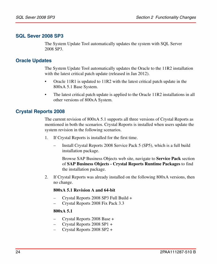
SQL Sever 2008 SP3
The System Update Tool automatically updates the system with SQL Server 2008 SP3.
Oracle Updates
The System Update Tool automatically updates the Oracle to the 11R2 installation with the latest critical patch update (released in Jan 2012).
• Oracle 11R1 is updated to 11R2 with the latest critical patch update in the 800xA 5.1 Base System.
• The latest critical patch update is applied to the Oracle 11R2 installations in all other versions of 800xA System.
Crystal Reports 2008
The current revision of 800xA 5.1 supports all three versions of Crystal Reports as mentioned in both the scenarios. Crystal Reports is installed when users update the system revision in the following scenarios.
1. If Crystal Reports is installed for the first time.
– Install Crystal Reports 2008 Service Pack 5 (SP5), which is a full build installation package.
Browse SAP Business Objects web site, navigate to Service Pack section of SAP Business Objects - Crystal Reports Runtime Packages to find the installation package.
2. If Crystal Reports was already installed on the following 800xA versions, then no change.
800xA 5.1 Revision A and 64-bit
– Crystal Reports 2008 SP3 Full Build +– Crystal Reports 2008 Fix Pack 3.3
800xA 5.1
– Crystal Reports 2008 Base +– Crystal Reports 2008 SP1 +– Crystal Reports 2008 SP2 +

Section 2 Functionality Changes Internet Explorer 9
2PAA111287-510 B 25
– Fix Pack 2.7
Internet Explorer 9
The current revision of 800xA 5.1 supports Internet Explorer 9.
VMware ESX (i)
The current revision of 800xA 5.1 supports VMware ESX (4.1) and VMware ESXi (4.1, 5.0, and 5.1).
Internet Protocol Security (IPsec) Configuration ToolThe Internet Protocol Security (IPsec) is a protocol suite for securing Internet Protocol (IP) communications by authenticating and encrypting each IP packet of a communication session.
A new tool, IPSec Configuration Tool, assists in configuring IPSec to protect the communication between clients and servers that are members of the Active Directory Domain in the 800xA system.
It also offers the possibility to allow system nodes to communicate without using IPSec towards explicitly defined nodes that do not support IPSec.
The tool can configure IPSec for a newly installed system but also for an existing system using System Version 5.1 or later versions.
Licensing and Automation SentinelThe current revision of System 800xA 5.1 is a licensed product as part of the Automation Sentinel Software Lifecycle program. The System 800xA 5.1 Revision A and the Feature Pack along with the later software releases requires a valid Automation Sentinel license and a valid system license to install and use the release.
The user can install the current release of System 800xA 5.1 with the following condition.
Systems have a valid System 800xA 5.1 license and a valid Automation Sentinel subscription, which is validated by the Automation Sentinel feature.

System Installer (Automated Installation) Section 2 Functionality Changes
26 2PAA111287-510 B
System Installer (Automated Installation)The following are the functionalities introduced for System Installer in 800xA 5.1:
• Upgrade 800xA 5.0 SP2 to 800xA 5.1
An upgrade information file from the current version is used to generate Setup Packages for installing the upgrade.
• Install 800xA Common Third Party Software
800xA Common Third Party Install Tool runs automatically to install third party software common to all 800xA System nodes.
• Removed support for installation or upgrade of 800xA Systems with 800xA for DCI
This version of System Installer does not support installation of 800xA for DCI.
Base SystemThis section describes the functionality changes and additions done to Base System in 800xA 5.1.
New Functions for 800xA 5.1 Revision D
The following are the functionalities introduced in the current revision of 800xA 5.1:
If the above condition is not met by the systems, the license annoyance messages are displayed after updating the software versions to the current release of System 800xA 5.1.
Since 800xA for DCI is not included with the initial release of 800xA 5.1, alternate installation instructions are provided with the 800xA for DCI 5.1 release documentation.

Section 2 Functionality Changes New Functions for 800xA 5.1 Revision C
2PAA111287-510 B 27
Supported Operating Systems
System 800xA 5.1 version runs on 64-bit (x64) and 32-bit (x86) operating systems. The initial System 800xA 5.1 version was 32-bit and Revision A had separate media boxes for 64- and 32-bit operating systems. The later revisions and feature packs are in a single media supporting both options. New installations should be installed on 64-bit operating systems. However, if desired older hardware and available operating system licenses can be used, it is possible to install the 800xA software on a 32-bit operating system.
It is possible to install mixed 64- and 32-bit systems. The most common use case is when a client is added or exchanged. Here it is possible to use a 64-bit node with 64-bit operating system, even if the rest of the system is running on 32-bit. Exchanging a Connectivity Server or even an Aspect Server to a node running on a 64-bit operating system is possible under certain circumstances. It is recommended to discuss this with Product Management. Swapping nodes to a 32-bit operating system on a system generally running on a 64-bit operating system is not considered as a relevant use case and should not be done.
The supported operating systems, service packs, and hot fixes are listed in System 800xA 5.1, 5.0, 4.x, 3.1 Third Party Software (3BUA000500). This document can be found in ABB SolutionsBank.
The same capabilities and performance as the previously released 32-bit version apply also to the 64-bit version.
The US English version of the operating system is required even if a translation NLS package for System 800xA is used.
New Functions for 800xA 5.1 Revision C
No new functions are listed.
New Functions for 800xA 5.1 Revision B
The following are the functionalities introduced in the current revision of 800xA 5.1:

New Functions for 800xA 5.1 Revision A Section 2 Functionality Changes
28 2PAA111287-510 B
Acknowledge all Visible Alarms
Added the possibility to configure the users who can access Acknowledge All Visible Alarms in the context menu. For more information, refer to System 800xA Engineering Process Graphics (3BSE049230*) manual.
New Functions for 800xA 5.1 Revision A
The following functionality is introduced in the System 800xA 5.1 Revision A:
Timer support on Hiding Mask and Hiding Rule
When defining hiding conditions, the time required for an alarm to be hidden may be longer than the time the actual hiding condition is active. To achieve this, a new hiding off delay is introduced. When a hiding off delay is defined, alarms will remain hidden during the delay even if the hiding condition is inactive. The off delay can be applied to both the hiding mask (deactivation delay) and hiding rules (hiding off delay).
The Hiding Off Delay in the Hiding rule aspect view indicates the hiding delay in seconds for hidden alarms.
The Deactivation Delay in the Hiding mask aspect view indicates the delay in seconds for disabling the containing rules after deactivation of the mask activating condition.
New Functions for 800xA 5.1
The following are the new functions introduced for Base System in 800xA 5.1.
System Configuration Console
The tool System Configuration Console is used for changing the system settings such as load balancing, workplace creation, user administration, and security settings. This tool can be accessed through the Start menu.
Wide Screen Workplaces
A set of wide screen workplaces has been defined for 800xA 5.1. The workplaces and the corresponding settings can be created from an aspect in Workplace Structure > Web System Workplace. The available workplaces cover the

Section 2 Functionality Changes New Functions for 800xA 5.1
2PAA111287-510 B 29
resolutions: 1680x1050, 1920x1080 and 1920x1200 for both wide screen monitors and large operator workplaces.
Point of Control
Point of Control is used to move the operational responsibility between users and locations. This feature can be used to move the operational responsibility to a central control room during night shift and back to the local control rooms during day shift.
Point of Control uses the 800xA security features to assign, enforce, and move the responsibility. The responsibility is moved by a set of interaction dialogs performed during the responsibility transfer.
When changing the Point of Control, the following settings are changed:
• The security settings (defines what interaction that is allowed).• Alarm and event lists filtering.
Alarm Analysis
The Alarm Analysis function is an effective alarm management function that allows operators to monitor the quality of alarm system. It includes measurement and presentation of the following key performance indicators in graphical elements and reports:
• Number of Active, Unacknowledged, Hidden, and Shelved alarms• Alarm rates and Average, Max number of alarms per hour• Average time to acknowledge alarms • Percentages of alarms above Acceptability level (user defined)• Percentages of alarms above Intense level (user defined)• 20 most frequent alarms • 20 alarms that were active for the longest time • 20 still active alarms that were active for the longest time • Runtime distribution of alarm priorities

Functionality Changes in 800xA 5.1 Section 2 Functionality Changes
30 2PAA111287-510 B
Alarm Shelving
Shelving is a facility where operators can shelve nuisance or standing alarms for a specified time. By “Shelving” an alarm, the alarm is temporarily removed from the alarm list.
The following are the two modes available to shelve an alarm:
• Standard shelving: Alarm is removed from the alarm list during a user-defined time and then appears again in the alarm list.
• One-shot shelving: Alarm is removed from the alarm list until it disappears.
Shelved alarms can always be accessed in a separate alarm list.
Functionality Changes in 800xA 5.1
The following are the functionality changes done to Base System in 800xA 5.1:
License Enforcement of 800xA 5.1
The 800xA 5.1 license is enforced, that is, System 800xA 5.1 cannot run with the license file of System 800xA 5.0.
Retrieval of System License ID
The system identity (SID) is created in ABB Software Factory. In 800xA System Versions prior to System Version 5.1, the SID is not available when the system is in operation.
In 800xA 5.1, this has been addressed and the SID can be retrieved from within the system.
On-line Upgrade
On-line upgrade to 800xA 5.1 is supported from the latest revision of 800xA 5.0.
Domain Controller in Combined Aspect and Connectivity Server
800xA 5.1 introduces support for configuration where the domain controller can reside in a combined Aspect and Connectivity Server.

Section 2 Functionality Changes Functionality Changes in 800xA 5.1
2PAA111287-510 B 31
Aspect Server Restart
Restart of 1oo2 Aspect Server has been improved.
If a change occurs to the directory when the two servers are separated, there is no way to see which one is correct. In this scenario, System 800xA versions prior to 800xA 5.1 required a manual restart. In 800xA 5.1, the restart is initiated automatically.
Installation on Multiple Disks
The 800xA 5.1 system performance can be further improved by allowing exclusive hard drives for system functions such as Aspect Directory in the Aspect Server and History Storage in the Connectivity Server. This is configured in the System Configuration Console tool.
Virtualized Configuration for 800xA
800xA 5.1 configured in a virtual environment now supports system sizes up to 40000 tags.
Multisystem Integration
Multisystem Integration has been extended to support the following in 800xA 5.1:
• Connectivity support for 800xA for AC 870P/Melody.
• Object Lock support for 800xA for Advant Master.
• Support for mixed traditional OCS connectivity in provider and subscriber systems.
Default Process Graphics Version
Process Graphics 2 is now the default graphics package. The Visual Basic based graphics version is still supported for customers performing the upgrade from previous versions of System 800xA.

System Services Section 2 Functionality Changes
32 2PAA111287-510 B
Acknowledge of all Alarms in a Display
The Acknowledge Visible Alarms tool allows the operator to acknowledge all alarms for all objects in a graphic display. No configuration is needed. This feature is included by default for all graphic displays.
System ServicesThis section includes functionalities introduced for System Services.
SMS and Email Messaging
This section includes functionalities introduced for the SMS and Email Messaging.
New Functions for 800xA 5.1 Revision D
The SMS and Email Messaging software includes the following enhancements in the System 800xA 5.1 Revision D:
• The e-mail message shall contain the alarm message in the body of the text along with the subject field.
Central Licensing System
This section includes functionalities introduced for the Central Licensing System.
New Functions for 800xA 5.1 Revision B
The Central Licensing System (CLS) software includes the following enhancements in the System 800xA 5.1 Revision B:
• The loss of connection to CLS Server node is reported on CLS client nodes by a communication failure error message only after a period of 24 hours. This functionality is applicable only in the scenario where Primary Aspect Server (CLS Server Node) node is restarted or becomes unavailable due to maintenance activity.
New Functions for 800xA 5.1 Revision A
The Central Licensing System (CLS) software includes the following enhancements in the System 800xA 5.1 Revision A:

Section 2 Functionality Changes Diagnostics Collection Tool
2PAA111287-510 B 33
• Native Language Support for German, French, Chinese, Spanish, Swedish, and Russian for global annoyance popup messages.
• Loss of connection to CLS Server node is reported on CLS Client nodes by a communication failure error message. Subsequently, annoyance messages for Temporary or Invalid licenses are reported only if the CLS Server remains unavailable for more than 24 hours.
New Functions for 800xA 5.1
The following are the new functionalities introduced for the System Services in 800xA 5.1:
• In SMS and e-mail Messaging, Object Description field is added to Message Configuration.
• In Licensing, License Entry application displays System Identifier (SID) key in product properties.
Diagnostics Collection Tool
This section includes functionalities introduced for the Diagnostics Collection Tool.
New Functions for 800xA 5.1 Revision D
The following are the changes done to Diagnostics Collection Tool (DCT) in 800xA 5.1 Revision D:
• The System 800xA Performance Data plug-in is used to collect the performance related data in the standard xml format to be analyzed by My Control System portal and eventually reports are created for the users.
New Functions for 800xA 5.1 Revision C
No new functions for 800xA 5.1 Revision C for Diagnostics Collection Tool.
New Functions for 800xA 5.1 Revision B
The following are the changes done to Diagnostics Collection Tool (DCT) in 800xA 5.1 Revision B:

Engineering Studio Section 2 Functionality Changes
34 2PAA111287-510 B
• The collection files are split into multiple equal parts before downloading the files from remote nodes. The size of the files can be configured using the DCT Options dialog box.
• A new feature is added to the Diagnostics Collection Tool for the data collection for consistency analysis of the installed 800xA System and associated software products. It allows data collection in simple steps. This information is to provide for the ABB service team for software consistency analysis.
New Functions for 800xA 5.1
The following are the changes done to Diagnostics Collection Tool (DCT) in 800xA 5.1:
• System Checker Tool is merged with the DCT. System Checker Tool functions are consolidated into DCT plug-ins.
• PPA Diagnostics Data is consolidated into Log Files plug-in.
• Windows Error Reporting (WER) replaces Dr. Watson plug-in.
Engineering StudioThis section includes functionalities introduced for the Engineering Studio.
New Functions for 800xA 5.1 Revision D
Subscription of Live Data functionality
Following are the changes in Subscription of live data functionality:
• From the following user can enable only one option at a time:– Subscribe for Live Data All Output Ports– Subscribe for Live Data For Connected Output Ports– Subscribe for Live Data– Subscribe for Live Data For All diagrams
• Subscribing the live data for a current page will subscribe all the pages in that diagram.

Section 2 Functionality Changes New Functions for 800xA 5.1 Revision D
2PAA111287-510 B 35
Paste Rename Functionality
In the regular copy paste operation names are automatically decided by the function settings, where as, Paste Rename functionality enables renaming of Function Diagrams and its various components interactively.
Figure 1. Paste Rename functionality

New Functions for 800xA 5.1 Revision C Section 2 Functionality Changes
36 2PAA111287-510 B
Synchronization between Control Builder Name aspect and Name aspect
Function Designer extensions enable synchronization between Name aspect and Control Builder Name aspect of an objects in 800xA System. In case engineering is not carried out using Function Designer, synchronization can be disabled. A new function setting has been introduced, which can be created under the Main View of the function settings aspect, and in this the Value can be set to False to disable the synchronization.
New Functions for 800xA 5.1 Revision C
No new functions are listed.
New Functions for 800xA 5.1 Revision B
No new functions are listed.
New Functions for 800xA 5.1 Revision A
The following are the functionalities introduced in the System 800xA 5.1 Revision A:
• Label_Report.xlsx
A New template is added in the Engineering Templates folder.
Function Settings
The following two new settings are added in Function Settings:
• Config Data For SFC
• Diagram Suffix String
These settings are used by SFC viewer Feature Pack versions to navigate from action window.
New Functions for 800xA 5.1
The following are the new functionalities introduced for the Engineering Studio in 800xA 5.1:

Section 2 Functionality Changes Function Designer
2PAA111287-510 B 37
Function Designer
In 800xA 5.1, Function Designer has been modified to provide improved engineering efficiency. Menu options and toolbars in Function Designer have been optimized and redefined to reduce complex engineering efforts.
Enhanced error tracking, configuration data generation performance, reduced code block sorting loops, and standardized XML interfaces are also implemented to improve the performance of Function Designer. 800xA 5.1 introduces the Diagram and inter-application communication features to simplify the integration of Function Designer with Control Builder M.
DIAGRAM and Single Control Module
800xA 5.1 supports engineering using Function Designer based on DIAGRAMs and Single Control Modules. The DIAGRAM is less complex and has more user-friendly features. DIAGRAMs use the new graphical FDCodeBlock language in Control Builder M. Each DIAGRAM generates a corresponding FuDCodeBlock in Control Builder M on generating configuration data. The Diagram aspect indicates the newly created Function Diagrams in 800xA 5.1.
DIAGRAM does not replace Single Control Module based Function Diagrams. To achieve a smooth system upgrade from previous system versions, the Single Control Module diagrams remain unaffected during the upgrade.
• Nested Diagrams:
Creation of nested Function Diagrams using the Diagram aspect without any diagram parameters is supported in the Functional Structure.
Control Builder M and Control Structure maintain a flat diagram structure, so it is recommended to maintain a flat diagram structure in the Functional Structure as well.
• Connection and Direction Rules:
The direction of Control Module Type parameters can now be specified to improve the reliability of executing applications having Control Modules. Function Designer displays warnings and error messages in case the connections lead to undesired execution.
• Implicit Casts:

Function Designer Section 2 Functionality Changes
38 2PAA111287-510 B
Implicit casts are obsolete in the new DIAGRAMs to ensure that the engineering logics are more transparent in Control Builder M. An implicit variable is automatically generated while using Splitter and Joiner blocks along with the in-out ports.
• Page Connectors:
Interconnected function components in newly created Function Diagrams of 800xA 5.1 can be moved to other pages, based on the network connection rules between different pages of a Function Diagram.
• Splitter and Joiner blocks:
Splitter and Joiner blocks are available for only newly created Function Diagrams in 800xA 5.1.
Splitter and Joiner blocks that have Data Flow Order value:
– Establish the connection mapping between the structured data type and the basic data types.
– Assign constant values to basic data type, which are part of structured data type.
• Diagram Execution Order:
The order of DIAGRAM execution within an application can be explicitly defined in Control Builder M. It is possible to assign a task to the DIAGRAM folder in Control Builder M using the context menu.
Communication Variables and Global Variables
Communication Variables are available in Function Diagrams created in any system version (800xA 5.1 and earlier versions). Global variables are available only in Function Diagrams created prior to 800xA 5.1.
• Communication Variables:
– Used to connect various diagrams that are available within the same or different applications, controllers, and aspect directories.
– Supported on the parent level of Single Control Module based Function Diagrams.

Section 2 Functionality Changes Function Designer
2PAA111287-510 B 39
– Provide system-wide communication capabilities without the explicit need for automatic cross communication generation from Function Designer.
– Can not be mapped to CIs and IO modules.
– Dependent on data flow directions and each output communication variable must be unique in a system.
• Control Builder M Signal mapping to Global Variables:
Configuration data generation of Control Builder M signals in newly created Function Diagrams of 800xA 5.1 creates local variables instead of global variables.
Local variables can not be accessed from other applications such as I/O simulation.
• Global Variable access via X: Functionality:
Global variables can be accessed through the X: functionality. For example, global variables can be referenced on Single Control Module diagrams. Control Builder M project constants can be used to reference global settings on DIAGRAMs.
• 1: N Connection:
The Communication variable concept is based on directions and enforces 1: N connections for unidirectional data types and 1:1 connections for bidirectional data types. M: 1 or M: N connections for variables within a controller can be implemented using MMS access variable code.
Caching
If the function setting CachingEnabled is set to True, caching is enabled and diagram modifications are not saved to aspect directory until Save operation is performed. This increases the engineering performance in a multi node environment, especially when working with sequences. Some functional discrepancies may occur.
By default, the function setting CachingEnabled is set to False.

Document & Parameter Manager Section 2 Functionality Changes
40 2PAA111287-510 B
Migrate Single Control Modules to DIAGRAMs
Export Diagram Data / Import Diagram Data in Function Designer enable the users to migrate the existing Single Control Modules (Function Diagrams created up to 800xA 5.0 SP2) to Diagrams.
The engineering logics created in Function Diagrams using earlier system versions can be exported through Function Designer to a XML file and re-imported to a newly created Function Diagram created in 800xA 5.1.
After migrating the Single Control Modules to DIAGRAMs, delete the existing connections between the Local Variables, Control Builder M signals, and Diagram References and establish new connections. Sequence blocks are excluded from this functionality.
Improved Difference Report in Import/Export Tool
Difference report feature in the Import/Export tool is improved in 800xA 5.1 to provide a detailed comparative report for additions / deletions / modifications between Function Diagrams present in the .afw files and the DIAGRAMs in the system.
Document & Parameter Manager
This section includes functionalities introduced for the Document & Parameter Manager.
Aspect Blob
Parameter Manager stores the parameter and document aspect property data and the parameter aspect category definitions in an aspect blob instead of Microsoft SQL Data Engine. The migration of the data for upgraded projects is performed while restoring a system.
Bulk Data Manager
This section includes functionalities introduced for the Bulk Data Manager.
Section 2 Functionality Changes AC 800M
2PAA111287-510 B 41
Engineering Templates
Some Bulk Data Manager templates available in earlier versions prior to 800xA 5.1 are obsolete.
The following templates are available in 800xA 5.1:
• BDM_DiagramRef_Var_Adv.xlsx • BDM_DiagramRef_Var_Basic.xlsx • BDM_for_FunctionDiagrams.xlsx • LogConfig.xlsx • TrendConfig.xlsx
AC 800MThe functionality changes related to Control Software for AC 800M in the 800xA System Version 5.1 Revisions include the following:• New Functions in System Version 5.1 Revision C, page 42• New Functions in System Version 5.1 Revision A, page 47.• Discontinued and Replaced Functions and Units, page 50.
For functionality changes made in Control Software for AC 800M in 800xA System Version 5.1 and 5.0 SP2 revision, refer System 800xA Release Notes New Functions And Known Problems (2PAA106188-510).
For information on SIL (Safety Integrity Level) conformance according to IEC 61508 or other applicable safety standards, refer to the manual System 800xA Safety AC 800M High Integrity Safety Manual(3BNP004865*).
The term Control Builder refers to Control Builder M Professional.The term OPC Server refers to OPC Server for AC 800M.The term Modem refers to modems that are configured and controlled by a controller. It does not refer to modems that are transparent for the controller.The term Controller refers to a Process Automation (PA) Controller. If it is a High Integrity Controller, the text will say High Integrity or HI Controller.

New Functions in System Version 5.1 Revision D Section 2 Functionality Changes
42 2PAA111287-510 B
New Functions in System Version 5.1 Revision D
INSUMCommlib
• InsumReceive block
INSUM receive blocks may stop and show status-19 after warm re-configuration. This problem is fixed in INSUMCommlib.
New Functions in System Version 5.1 Revision C
PROFINET CI871
• Support for ABB standard drive ACS 880 with FENA-11 and PROFINET
The new hardware library – ABBDrvFenaCI871HwLib – provides the PROFINET connectivity to the new ACS 880 drive via the communication adapter FENA-11.
• New motor starters for MNS iS on PROFINET
The MNS iS hardware library – ABBMNSiSCI871HwLib – offers support for the two new motor starter types – Sace Circuit Breakers (Sace CBR) and DC Feeder (DC MFeed).
Fieldbus FF CI860
• Support for accessing CI860 via AC 800M web interface
Like PROFIBUS with CI854 and PROFINET with CI871, FF HSE with CI860 is now also accessible via the AC 800M web interface. The list of supported functions is described in the AC 800M Foundation Fieldbus HSE (3BDD012903*) manual.
Standard Libraries
This topic lists the objects that are modified in the libraries delivered with Control Builder in this revision. For a complete list of fixed problems, including these changes, refer to System 800xA 5.1 Revision C Release Notes Fixed Problems (2PAA109826-510).

Section 2 Functionality Changes New Functions in System Version 5.1 Revision C
2PAA111287-510 B 43
The objects that are modified in the libraries are:
• ControlBasicLib
– PidLoop, PidLoop3P, PidCascadeLoop, and PidCascadeLoop3P
The problem that caused PID function block windup if the signal connected as Pv (Process Value) to the slave controller was outside the range of 0 - 100%, has been corrected.(800xACON-OL-5000-086)
• ControlStandardLib
– AccelerationLimCC
AccelerationLimCC can be used to limit the output value from VelocityLimiterCC, without any errors. In this case, the component ControlConnection.Backward.MaxReached or ControlConnection.Backward.MinReached of the input signal node of AccelerationLimCC is set to true.
– PidCC
The change of sign in control error (deviation of Pv in both positive and negative directions around the Sp value) does not lead to any unwanted behavior in PID.(800xACON-OL-5101-015)
– VelocityLimiterCC
A backward change in the input value (from high to low) does not result in a wrong value from VelocityLimiterCC.(800xACON-OL-4100-053)

New Functions in System Version 5.1 Revision C Section 2 Functionality Changes
44 2PAA111287-510 B
– ManualAutoCC
– The display element of ManualAutoCC appears without any error even if its input CC is not connected.(800xACON-OL-5100-081)
– From the normal faceplate, extended faceplate, and reduced faceplate of ManualAutoCC, it is possible to change the manual value.(800xACON-OL-5100-075)
– AnalogInCC
The component ControlConnection.Forward.Status displays the Uncertain status for underflow and overflow.(800xACON-OL-5100-084)
• ControlAdvancedLib
– PidAdvancedCC
– The calculation of the derivative part has no dependency on the selected dead zone, which means that the output signal may change even if the difference between Sp and Pv is less than the dead zone value. Small changes is Pv is filtered by a special low pass filter assigned for the derivative part.(800xACON-OL-5101-015)
– The windup function is removed for controllers without an integral part. This helps in removing the oscillations if these controllers are used in combination with MaxCC or MinCC.(800xACON-OL-5020-051)
– Any change to the value of Dead Zone does not immediately affect the PID output.(800xACON-OL-5101-015)
Section 2 Functionality Changes New Functions in System Version 5.1 Revision C
2PAA111287-510 B 45
• ProcessObjBasicLib
– BiSimple, UniSimple
The graphic element displays Data Quality (IO status) indication.
– BiCore, BiSimple(M)
During restart after a power failure, the process objects based on BiCore start up in the manual mode.(800xACON-OL-5000-090, 3BSE047421D0119)
• ProcessObjExtLib
– MotorValveM
The pulse setting is also involved in the signal evaluation. This results in the correct behavior of the output if PulseOut is set to true.(800xACON-CN-5101-018)
– Bi(M), MotorBi(M), MotorValve(M)
During restart after a power failure, the process objects based on BiCore start up in the manual mode.(800xACON-OL-5000-090)
• ProcessObjInsumLib
– MCUBasic(M), MCUExtended(M)
During restart after a power failure, the process objects based on BiCore start up in the manual mode.(800xACON-OL-5000-090)
• SeqStartLib
– Sequence2DHeader
In the faceplate of Sequence2DHeader, the arrows are disabled when the sequence has reached the end position.(800xACON-OL-5020-049)

New Functions in System Version 5.1 Revision C Section 2 Functionality Changes
46 2PAA111287-510 B
• SignalBasicLib
– SignalBasicInReal
When there is an underflow or overflow of the input signal, the Warning and Error parameters are set to true.(800xACON-OL-5101-014)
• SignalLib
– SignalRealCalcInM
The Trend aspect of SignalRealCalcInM shows the trend for Out.Forward.Value, which is the same as the logged value in the Log Configuration aspect.(800xACON-CN-5000-100)
– SignalInRealM, SignalSimpleInRealM
The component ControlConnection.Forward.Status displays the Uncertain status for underflow and overflow.(800xACON-OL-5100-084)
– SignalInRealM, SignalSimpleInReal(M)
When there is an underflow or overflow of the input signal, the Warning and Error parameters are set to true.(800xACON-OL-5101-014)
• SignalSupportLib
– ErrorDetection
When there is an underflow or overflow of the input signal, the Warning and Error parameters are set to true.(800xACON-OL-5101-014)
• SupervisionBasicLib
– SDInReal
When there is an underflow or overflow of the input signal, the Warning and Error parameters are set to true.(800xACON-OL-5101-014)

Section 2 Functionality Changes New Functions in System Version 5.1 Revision A
2PAA111287-510 B 47
New Functions in System Version 5.1 Revision A
This section includes functionalities introduced for AC 800M in System Version 5.1 Revision A.
Control Network
• Network storm protection for Controller network
The Control Network filter in PM8xx now provides a general protection against excessive network traffic, not only against network loops.
Field Networks
• Network filter protection for Fieldbus network
A network filter has been introduced to provide protection against, for example, network storms. These functions have been introduced in the following communication modules:
CI857 (INSUM)
CI867 (MODBUS TCP)
CI868 (IEC 61850)
CI871 (PROFINET)
CI873 (EtherNet/IP)
• Handling of Sub Status bits
I/O handling is enhanced to handle sub status bits (OPC status). In this release, this feature is used by CI871 (PROFINET IO).
Standard Libraries
Objects that have been added to the libraries delivered with the Control Builder, are:
• ProcessObjExtLib
– MotorBi, MotorBiM
PriorityCmd01 will not generate an alarm.

New Functions in System Version 5.1 Revision A Section 2 Functionality Changes
48 2PAA111287-510 B
– MotorUni, MotorUniM
PriorityCmd01 will not generate an alarm.
– ValveUniM
A second output (Out0) has been added to support bi-stable valves.
– SimpleUni, SimpleUniM
The display elements has been updated to be able to show valve-, motor- and a generic icon.
– Uni, UniM
The display elements has been updated to be able to show valve-, motor- and a generic icon.
• SignalLib
– SignalRealCalcOutM
Handling of alarm acknowledgement has been corrected, the signal will wait for both signal quality and alarm acknowledgement before ramping up.
• AlarmEventLib
– ProcessObjectAE
Alarm detection will now be done within one scan.
• ProcessObjDriveLib
– ACStdDrive, ACStdDriveM
Reset button added to the Main Faceplate.
– DCStdDrive, DCStdDriveM
Reset button added to the Main Faceplate.
– EngDrive and EngDriveM
Reset button added to the Main Faceplate.
• All standard libraries

Section 2 Functionality Changes New Functions in System Version 5.1 Revision A
2PAA111287-510 B 49
1131 Standard Libraries have been updated to handle diverse sub status in I/O data types. In this release, this feature is used by PROFINET IO devices.
For users handling status I/O status int in application code or user defined libraries, the status should be evaluated from the Q bits (major quality bits in OPC standard). 00xxxxxx gives Bad quality, 11xxxxxx gives Good quality and 01xxxxxx gives Uncertain quality. For Uncertain, the sub status and two limit status bits are used.16#55 (01010101) overflow and 16#56 (01010110) underflow are treated as Good values; other values are treated as Uncertain.
OPC Server
• Manual handling of files for OPC server
Due to the changes for “Improved user scenario when using Compact Flash cards in Controllers” there are some new files that need to be handled if manually backing up or copying download files for OPC server. The additional files has the following extensions .cdobXml,.rrsbXml and .ctdbXml.
New Hardware Units
• New Firmware for Communication Module LD 800DN
New firmware for Linking Device for DeviceNet used with CI873 for EtherNet/IP. The user should ensure that the LD 800DN is updated with the latest firmware. For the latest firmware list of Compatible firmware, refer to System 800xA 5.1 Revision A Release Notes New Functions and Known Problems (2PAA107250-510).
Backup Media
• Improved user scenario when using backup media in Controllers
It is now possible to create a backup media and still go online with Control Builder.
This functionality is not supported in the AC 800M High Integrity controller.
• Time zone saved on backup media

Discontinued and Replaced Functions and Units Section 2 Functionality Changes
50 2PAA111287-510 B
The configured time zone of the Control Builder used to create the application image to backup media will be saved to the backup media and used in the Controller when starting up.
This functionality is not supported in the AC 800M High Integrity controller.
Discontinued and Replaced Functions and Units
Unconnected Control Module string parameters no longer truncated to 40 characters length
In earlier versions initial value for unconnected string parameters has been truncated to 40 characters independent on the defined string length. If the parameter was connected, the length was limited by the connected variable. The length of unconnected string parameter will now be as long as defined by the parameter definition. For system generated strings the length will still be 40 characters.
New Functions in 800xA 5.1
Support for PM891
The PM891 controller is a new controller with 256-Mbyte of memory and performance data which is approximately three times the performance of PM864. PM891 may be used in both single and redundant configurations. The Controller does not have any local ModuleBus, and hence cluster modem is always needed when S800 I/O on ModuleBus is used.
Support for AF100 using CI869
The CI869 Communication Interface makes it possible for an AC 800M Controller to be connected to AF100. This is achieved using the AF100 hardware library (CI869AF100HWLIB). CI869 has support for line and CI module redundancy.
CI869 is not supported in AC 800M HI.

Section 2 Functionality Changes New Functions in 800xA 5.1
2PAA111287-510 B 51
Support for PROFINET IO using CI871
The CI871 Communication Interface makes it possible for an AC 800M Controller to be connected to a PROFINET IO network. This is achieved using the PROFINET IO hardware library (CI871PROFINETHwLib). The Device Import Wizard included in Control Builder can be used to import definition files for PROFINET IO. CI871 has no support for redundancy.
Support for MOD5 using CI872
The CI872 Communication Interface makes it possible for an AC 800M Controller to be connected to a MOD5 Controller. This is achieved using the MOD-To-MOD communication library (MTMCommLib) and the CI872 hardware library (CI872MTMHWLib). CI872 has support for CI module redundancy.
Support for DeviceNet using CI873
The CI873 Communication Interface makes it possible for an AC 800M Controller to be connected to the DeviceNet protocol via the gateway LD 800DN. This is achieved using the EtherNet/IP hardware library (CI873EthernetIPHwLib). The Device Import Wizard included in Control Builder can be used to import definition files for EtherNet/IP and DeviceNet.
Diagram
A new entity called Diagram is introduced in the Control Builder. A Diagram in Control Builder corresponds to a Diagram created by Function Designer. It is not possible to edit the Diagrams in Control Builder. The Function Designer is required for editing. However the compilation of the code can be done using Control Builder and online values can be seen and changed from the Control Builder. Instead of the MMS communication generated by Function Designer, Communication Variables
CI871 is not supported in AC 800M HI.
CI873 is not supported in AC 800M HI.

New Functions in 800xA 5.1 Section 2 Functionality Changes
52 2PAA111287-510 B
(Inter Application Communication) can be used to set up Communication between Diagrams. The maximum number of Diagrams per application is 100.
Communication Variables - Inter Application Communication (IAC)
Communication Variables - Inter Application Communication (IAC) can be used for communication between applications running in the same or different controllers. IAC can handle communication variables with a size that is less than or equal to 1400 byte with a maximum of 1000 components. Communication Variables can be defined in the POU types: Diagram, Program and Single Control Module located in the Application root. The status of a Communication Variable can be accessed in the application code by adding:status to the communication variable, for example CVApp1:status. The status type is of the data type dword. ISP values can also be configured for Communication Variables. The reverse attribute is used to determine value ownership of bidirectional communication. A diagnostic overview of Communication Variables can be viewed from the Remote System dialog in Control Builder. Communication Variables can be used instead of the MMS communication that is generated by Function Designer. Communication Variables are not supported for Load evaluate Go.
Engineering Environments — Project Explorer
• Enhancement to Connect Library and Connect Application Dialogs – The dialog for connecting libraries to libraries, applications, or controllers, and the dialog for connecting applications to controllers are enhanced. They now support multiple selection of items. The connect operation can also be done using drag-and-drop in the Project Explorer, that is, drag an application to a controller instead of using the connect application dialog.
• Improvements in the Message Pane of the Project Explorer – The performance of the message pane has been improved. It can now hold a lot of text without slowing down performance during compilation operations, etc. It has also been enhanced with icons for errors and warnings. This makes it easier to find these kinds of messages during a compilation and download operation.
Diagram is not supported in AC 800M HI.
Communication Variables are not supported in AC 800M HI.

Section 2 Functionality Changes New Functions in 800xA 5.1
2PAA111287-510 B 53
• Number of Applications per Controller – The maximum number of applications running in a controller has been increased to 32.
• Application Folder Object – In a Project there is support for a structuring object called Folder. The Folder object can be used to get a better overview of the applications in a project. One or several Folders can be inserted below the Applications object. A Folder object can contain one or several applications, and a Folder can be placed in other Folders.
• Increased maximum length for library name – The maximum length on library names is increased from 20 to 32 characters. This applies to both 1131 libraries and hardware libraries.
• Support for more than 255 major library versions – The maximum major version number for a library is increased from 255 to 32767.
Engineering Environments — Application Programming
• Reverse Attribute on Structured Data Types – On a component in a structured data type it is possible to set the reverse attribute to indicate the data flow direction. For example, a data type can have the attribute retain reverse. The reverse attribute enables compilation checks on Control Module parameters with direction attributes and forward and backward components. The reverse attribute is also used for Inter Application Communication to determine value ownership for bidirectional communication. All libraries that are delivered together with the Control Builder are updated with the reverse attribute.
• Parameter Direction for Control Modules – It is now possible to define the direction for a Control Module parameter. The different directions are: in, out, in_out, or unspecified. Unspecified has the same behavior as earlier versions where no parameter direction could be set on control modules. The direction for Control Module parameters in Control Module types created in earlier system versions will default to Unspecified after upgrading to 800xA 5.1. Parameters in libraries delivered with AC 800M connects have been set to a specific direction where applicable.All libraries that are delivered with the Control Builder are updated with the Unspecified attribute when applicable.

New Functions in 800xA 5.1 Section 2 Functionality Changes
54 2PAA111287-510 B
Engineering Environments — Improved Navigation in the FBD and LD Editors
In the FBD/LD Editors is it now possible to:
• Scroll left/right in view using SHIFT + Scroll wheel• Zoom in/out in view using CTRL + Scroll wheel
Engineering Environments — Compile and Download
• Task Analysis Tool – A tool called Task Analysis is available to analyze the tasks in the controller. The tool helps the user identify potential problems during download due to task settings. The tool will prevent download if severe problems are found.
• Compiler Checks Parameter Direction – A compilation check verifies that code in a Control Module does not write to its input parameters. It is allowed to both read and write to output parameters. Special rules apply for parameters of structured data types containing reverse components:
– A control module is not allowed to write to reverse components in output parameters.
– It is allowed to write to reverse components in input parameters.
• Compilation Warnings Saved in Difference Report Files – Compiler warnings shown in Difference Report files are saved so that they can be viewed when opening a saved Difference Report from an earlier download.
• Prohibit Re-configuration of Max no. of Forces Less Than Current Active Forces – If the configuration for max number of allowed forces is set to a lower value than previous, a new check will provide a warning during download. If the warning is ignored and download is continued the controller will shut down if the actual number of forces exceeds the new configured value.
• Inhibit Download when Difference Report is not Complete – If the difference report fails to show the differences for any reason, the download to the HI controller is stalled.
Section 2 Functionality Changes New Functions in 800xA 5.1
2PAA111287-510 B 55
Engineering Environments — Hardware Configuration
• User Defined Names on Hardware Units – It is possible to define an additional name to a hardware unit name by right-clicking on the hardware object and selecting Rename, that is, a DI810 can be renamed to Valves DI810.
• Hardware Configuration – The Move To functionality on hardware units is improved. If the new position that is selected in the Move To dialog is occupied, the user will be prompted if the units should swap places (functionality before 800xA 5.1) or if the unit (and subsequent units) on the target position should be moved down one position.
• Device Import Wizard – The Device Import Wizard is improved in this release to also handle definition files for PROFINET IO, EtherNet/IP, and DeviceNet. It is also possible to make configuration changes and change diagnostic settings (for example mapping to hardware status or alarm settings) on a type in the Device Import Wizard without the need for a full import of the definition files.
Operation
• Shelving Indication in Faceplates – In the faceplates that are delivered in the AC 800M Connect there is an indication for shelved alarms.
• Increased performance for OPC write – The performance of OPC write requests from an OPC Client is increased by an average of 200 to 300 ms.
• Replace AC800MC_Trace.log with use of AfwApplog – The method of enabling debug printouts for the AC800M aspect system (AC800MC_Trace.log) is replaced with standard 800xA AppLog functionality.
Control Network
• RNRP Loop Protection – In the controller, there is a protection against network loops enabled by default. If a network loop is detected then the network interface of the controller is disabled and a system event about this
Shelving indication is available only in the operator graphics that is based on Process Graphics 2 which is installed by Default. The faceplates included in the operator graphics based on Visual Basic, that was installed by default in previous system versions, do not support shelving.

New Functions in 800xA 5.1 Section 2 Functionality Changes
56 2PAA111287-510 B
issue is generated. When the network interface is disabled due to a network loop, the controller will still run, but may not be able to communicate depending on whether both network interfaces or only one is/are disabled. The controller will detect when the network loop has been resolved and then the interface will be enabled again.
Control and IO
All supported S900 input modules have support for ISP.
Standard Libraries
Objects that have been added to the libraries delivered with the Control Builder, are:
• New Firmware Functions:
– ClearBit – sets one specified bit to 0 in a word/dword.
– ClearBits – sets several specified bits to 0 in a word/dword.
– GetCVStatus – used to get the status of a Communication Variable.
– RealInfo – used to get information about a real value (if it is within the allowed range). RealInfo is typically used for check of overflow/underflow of arithmetic operations.
– SetBit – sets one specified bit to 1 in a word/dword.
– SetBits – sets several specified bits to 1 in a word/dword.
– TestBit – checks if one specified bit is 1 in a word/dword.
– TestBits – checks if several specified bits are all 1 in a word/dword.
• BasicLib:
Detection of Reset Forces from SM810/811 in ForcedSignals(M) – In the function block type ForcedSignals and the control module type
In AC 800M HI, the RNRP Loop Protection is not enabled by default but can be enabled by a special parameter as described in the Technical Description 3BSE060651*.
The new firmware functions are not supported in AC 800M HI.

Section 2 Functionality Changes New Functions in 800xA 5.1
2PAA111287-510 B 57
ForcedSignals(M) a parameter called SMResetControllerForces is added. The parameter is used to indicate when the reset forces input on the SM810/811 is activated.
• ProcessObjLib:
– UniCore – During the startup after a power failure, the objects are updated (mandatory) to reflect the actual state of the connected feedback signals. In earlier versions this was only performed in case a signal quality transfer is detected from bad to good (refer to technical description 3BSE047421D0071).
– BiCore – During the startup after a power failure, the objects are updated (mandatory) to reflect the actual state of the connected feedback signals. In earlier versions this was only performed in case a signal quality transfer was detected from bad to good (refer to technical description 3BSE047421D0071).
• ProcessObjExtLib:
– MotorValve – The MotorValve function block type is suitable for graphical control and supervision of a bidirectional (two activated position) motor valve. This object has operator graphics in Process Portal.
– MotorValveCC – The MotorValveCC function block type is suitable for graphical control and supervision of a bidirectional (two activated position) motor valve. The input interface is of type control connection that can be connected to an output object from a control loop. This object has operator graphics in Process Portal.
– MotorValveM – The MotorValveM control module type is suitable for graphical control and supervision of a bidirectional (two activated position) motor valve. This object has operator graphics in Process Portal.
• GraphicSupportLib
– Graphical Elements for AC 800M Graphics Available in GraphicSupportLib – The graphical elements that are used by the AC 800M Connect graphics are available in the library GraphicSupportLib. By using the elements in GraphicSupportLib it is possible to create user defined graphics with the same look and feel as the graphics that are delivered for the standard AC 800M libraries. The

New Functions in 800xA 5.1 Section 2 Functionality Changes
58 2PAA111287-510 B
elements can be accessed from the three tool boxes in the Graphics Builder that starts with AC 800M.
SFC Viewer
The Sequential Function Chart (SFC) Viewer is a tool in the System 800xA that allows the Operator to display SFC structures with live data for active steps and transitions on Operator workplaces without additional installation of a controller configuration tool.
A transition in an SFC code block can use more than two inputs. This is now shown in a compact format with only one block in the SFC Viewer.
New Hardware Units
• New Controller
– PM891– The PM891 controller is a new controller with 256-Mbyte memory and performance data which is approximately three times the performance of PM864.
• New Communication Modules
– CI869 – Communication interface for AF100– CI871 – Communication interface for PROFINET IO– CI872 – Communication interface for MOD5– CI873 – Communication interface for ETHERNET/IP – LD 800DN – Linking Device for DeviceNet
• New I/O Units
– DSDP 160 – Support for the S100 I/O board DSDP 160 is added.
Legacy Protocols
• MODBUS support for FC23 – Modbus now has support for FC23, which allows both writing and reading registers in one telegram. This improves performance when reading time-stamped data.
MODBUS FC23 is not supported in AC 800M HI.

Section 2 Functionality Changes Discontinued and Replaced Functions and Units in 800xA 5.1
2PAA111287-510 B 59
• Handling of negative values on Modbus TCP – It is now possible to transmit negative values on Modbus TCP when using signed data types (DINT and INT). All values over 32767 will be translated into negative values when signed data types are used with Modbus function blocks. Signal range is from -32768 to 32767.
Maintenance
• Detailed Difference Report at Import – It is now possible to make a detailed difference report when importing an *.afw file in the Import Export tool in Process Portal. It is possible to see changes (example 1131 code) or changes of variable declarations in the detailed difference report.
• Load Firmware to Removable Media from Project Explorer – Right-clicking on a controller in Project Explorer provides access to the Load Firmware to Removable Media context menu. Using this menu command causes the selected card to be formatted (if necessary) and then the firmware will be placed on the card.
Discontinued and Replaced Functions and Units in 800xA 5.1
Engineering Environments — Project Explorer
• Applications Not Populated at Creation – When a new application is created in the Control Builder it is not automatically populated, that is, the user needs to right-click the application and select New > Data Type, Function Block Type, Control Module Type, Single Control Module, Control Module or Program.
• New Icons in Project Explorer – The icons of the objects in Project Explorer are changed. Some of the tools in the Control Builder, for example, difference report and search and navigation also have new icons. There will be a mix of new and old icons for upgraded projects in Plant Explorer.
• Compact Flash Context Menu on Controller in Project Explorer – In previous versions the Compact Flash context menu option used to generate an image of the files was needed to load the application from a compact flash card. The Compact Flash context menu option is replaced with Download to Removable Media.

Discontinued and Replaced Functions and Units in 800xA 5.1 Section 2 Functionality Changes
60 2PAA111287-510 B
• Compact Flash Card Renamed to Backup Media – As some of the controller types use CF cards and others use SD cards, some of the menu options and error messages are renamed in Backup Media.
• Enabling of Toolbar buttons in the FBD/LD Editor changed – To avoid high CPU load in the PC, when a deep structured FB type is instantiated, the enabling of some toolbar buttons in the FBD/LD editor has been changed. Instead of cyclically updating the toolbar, it is now updated only on demand (demand as in, when a button is clicked).
Engineering Environments — Compile and Download
• Maximum Number of IO Variable Connects per Controller – The maximum number of variables that can be connected via I/O in a controller has been increased from 1000 to 50000. This is not supported in AC 800M HI.
• Changed Default value for Compiler Switch Implicit Cast – The default value for the Compiler switch Implicit Cast has been changed from Allowed to Error for SIL1-2 and SIL3.
• Maximum 12 S800 I/O-Modules on a ModuleBus Cluster at Hardware Simulation – Having more than 12 S800 I/O-modules on a ModuleBus cluster is not allowed, a compilation check in the Control Builder verifies this at download. This restriction is now also applicable for hardware simulation, that is, it will not be possible to download to a hardware simulated controller if more than 12 S800 I/O-modules are configured on a ModuleBus cluster.
S800 IO
• Changed Default Value of FJT Parameter in AI835, AI835A, and AI893TC – The default value of the Fix Junc Temp parameter in the IO modules AI835, AI835A, and AI893TC has been changed to 25.0.
• Changed Default Value of Signal Range Parameters in AO890 – The default value of the Signal range channel parameters in the IO module AO890 has been changed to 4-20 mA.
Six redundant S800 I/O-modules are counted as 12 modules.

Section 2 Functionality Changes Discontinued and Replaced Functions and Units in 800xA 5.1
2PAA111287-510 B 61
• Changed Default Value of Operation Mode and Shunt Mode Parameters in DP840 – The default value of the Operation Mode parameter in DP840 has been changed to Single (Operation Mode is called Redundant Mode when DP840 is used together with CI840). The default value of the Shunt Mode parameter in DP840 has been changed to Internal Shunt.
RNRP
• Multicast Enable Parameter Removed from RNRP Wizard – The Multicast Enabled parameter is removed from the RNRP Wizard because there is no requirement for this parameter.
Operation
• Operator Graphics Based on New Graphics Installed by Default – The operator graphics (Process Graphics) aspects (faceplates and graphical elements) that are installed by AC 800M Connect are now based on Process Graphics 2. The operator graphics based on Visual Basic, that were installed by default in previous system versions are now placed in a system extension and can be loaded to the system when needed.
• Hardware Status and Alarms are Translated - The OPC server now translates the status and bit information from the hardware to readable text in the Alarm and Event lists. Previously the information was presented in bit codes. Since the translated text is not NLS handled, it is possible in the OPC server to select if the text should be translated or if the status and bit information should be presented instead.
Installation
• Operating System - Due to the change from Windows XP to Windows 7, the icons and menus in the products are updated.
• Firmware for AC 800M High Integrity in Separate Library – The firmware for AC 800M HI is moved to the new library: BasicHIHwLib. In previous versions the firmware for AC 800M HI was located in BasicHwLib. The new library BasicHIHwLib is installed by loading the new system extension AC 800M HI Extension.
Discontinued and Replaced Functions and Units in 800xA 5.1 Section 2 Functionality Changes
62 2PAA111287-510 B
• Control Builder Uses Windows Heap instead of Own Heap – In previous System Versions the Control Builder had its own heap. This was configured in the Setup Wizard of the Control Builder. Configuration of the heap in Control Builder is no longer required.
• CI851 and CI852 Only Supported for Upgrade – The Communication Interfaces CI851 (PROFIBUS) and CI852 (FF) are only supported for upgrade of projects where these units are used. It is not possible to add new CI851 and CI852 units to a project. For new projects, CI854 shall be used instead of CI851 and CI860 replaces CI852. If a project that contains CI851 or CI852 units is upgraded to 800xA 5.1 it will still be possible to use the CI851 and CI852 units in the project.
License
• New License Required for 800xA 5.1 – A license valid for 800xA 5.0 SP2 is not valid for 800xA 5.1.
• CCP Licenses instead of CLP – From 800xA 5.1, the Controller Capacity Points (CCP) license is introduced. This replaces the Control License Points (CLP) license that was used in previous versions. The CCP license cost depends on the type of controller, that is, higher the CPU capacity, higher the license cost. The CCP is counted based on the type of controller used in the project.
Maintenance
• Default Firmware Selection in Firmware Information Dialog – Some controllers, for example PM865 can be updated with either PA firmware or HI firmware. The firmware information dialog now suggests the firmware most suitable for the current controller. If it is configured as a HI controller, the HI firmware is suggested and vice versa.
Backup Media
• Supported File System for Compact Flash cards in Controllers – The external compact flash cards in the Controller can now also handle FAT32. When using compact flash cards for firmware upgrades they must still be formatted for FAT16. There is a context menu available on the controller in the

Section 2 Functionality ChangesRestrictions and Preparations Before Start of Online Upgrade of HI
2PAA111287-510 B 63
Project Explorer called Load Firmware to Removable Media. This menu provides guidance through the process of configuring the card. A tool is included in the Control Builder to make it easier to format compact flash cards >2 GB for FAT16. This functionality is not supported in the AC 800M HI in this version.
Restrictions and Preparations Before Start of Online Upgrade of HI Controller
Refer to the System 800xA Release Notes New Functions and Known Problems (2PAA106188*) for important restrictions and preparations before starting the online upgrade of the HI Controller.
Considerations and Restrictions for Hardware Configurations in SIL3
Refer to the System 800xA 5.1 Release Notes New Functions and Known Problems (2PAA106188*) for important considerations and restrictions for hardware configurations in SIL3.
PLC ConnectThis section includes functionalities introduced for PLC Connect.
New Functions for 800xA 5.1 Revision D
The following are the functionalities introduced for PLC Connect in 800xA 5.1 Revision D:
• Delays are entered between telegrams for the Comli protocol.
New Functions for 800xA 5.1
The following are the functionalities introduced for PLC Connect in 800xA 5.1.
• Operator Action Text Groups
The parts of the default alarm text group that are related to operator actions, such as force, unforce, and control have been moved to an Operator Action Text Group which can now be selected in the Signal Configuration aspect. At the same time new texts have been added, it is now possible to set values for

Multisystem Integration Section 2 Functionality Changes
64 2PAA111287-510 B
force, force on, force off, and unforce; control, control on, and control off; enable control and disable control.
• Subfolders and Libraries for PLC Object Types
It is now possible to place PLC Connect object types in libraries or object type groups in the Plant Explorer. This can be used to create groups of object types for easier navigation.
• Timeout for Aspect Directory Connection
A timeout for monitoring the connection to the aspect directory has been introduced in 5.1; the default value of the timeout is 500 ms.
Multisystem IntegrationThis section includes functionalities introduced for Multisystem Integration
New Functions for 800xA 5.1
The following are the functionalities introduced in the System 800xA 5.1 functions:
Connect Method for Multisystem Integration
Connection between provider system and subscriber is not possible with an unknown user account. The connection is possible from the subscriber system to the provider system only when the user account is known in the provider system.
For more information on Connect Method for Multisystem Integration, refer System 800xA, Multisystem Integration (3BSE037076*).
Multisystem Integration supports the following connectivities:• 800xA for AC 800M.• 800xA for Advant Master.• 800xA for Safeguard.• 800xA for MOD 300.• 800xA for Harmony.
If the provider and subscriber belongs to the same Windows domain, a domain user account can be used. If the provider and subscriber belongs to different Win-dows domains or workgroups, a node local account has to be used.
Section 2 Functionality Changes SFC Viewer
2PAA111287-510 B 65
• 800xA for AC 870P/Melody.• PLC Connect.• PROFIBUS & HART.
SFC ViewerThis section includes functionalities introduced for the SFC Viewer.
New Functions for 800xA 5.1
The following are the functionalities introduced for SFC Viewer in 800xA 5.1:
• Transition Display
The transition display shows the stepping criteria for the selected transition in a Function Plan view perspective and a List view perspective. The Function Plan view displays the intermediate and final logic of the transition, providing a high level of supervision and control of the plant.
• Object Navigation
SFC Viewer supports navigation to the AC 800M controller objects from the transition Function Plan view and the List view. The object navigation feature is enabled for the transition criteria that are linked to specific controller objects.
Process Engineering Tool IntegrationThis section includes functionalities introduced for Process Engineering Tool Integration.
New Functions for 800xA 5.1
The following are the functionalities introduced in the System 800xA 5.1 functions:
The major functionality introduced for Process Engineering Tool Integration in 800xA 5.1 is Transformations (CAEX Transformer Integration).
The following are other minor features introduced for 800xA 5.1.

New Functions for 800xA 5.1 Section 2 Functionality Changes
66 2PAA111287-510 B
• Support for specifying the scope and naming convention of variables for the pure CB workflow.
• Support of an Object Reconciliation utility for the Functional Structure.
• Support for instantiation of function diagrams from templates to include references to output diagrams.
• Support for writing Control Properties of HW objects.
• Create objects in other structures (Asset, Documentation, Location).
• Support for SPI 2007 (8.0).
• Support SPF Adapter.
• Support for deleting objects in 800xA.
• Support for deleted/obsolete objects in INtools/SPI.
• Setting Start object in CAEX and 800xA for compare.
• Support FD templates in 800xA.
• Support Normally open/Normally closed field in INtools/SPI.
• Support for Control System tag in INtools/SPI.
• Support multiple networks.
• Support for Control Builder M data-types.
• Blank mapping file for creating new mapping file from scratch.
• Include object type comparison in Compare operation.
• Allow to select other fields in INtools/SPI to become object types.
• Bulk interface (Command-line).
• Pure Control Builder M workflow without signal objects (using variables).
CAEX Transformations (supports merging multiple INtools/SPI tags into one 800xA tag).

Section 2 Functionality Changes Removed functionality
2PAA111287-510 B 67
Removed functionality
Event Extended Options: This function is removed from PLC Connect. To receive e-mail or SMS notification on alarms, the ABB SMS and e-mail Messaging system should be used.
Device Management FOUNDATION FieldbusThis section includes functionalities introduced for Device Management FOUNDATION Fieldbus.
New Functions for 800xA 5.1
The following are the functionalities introduced for Device Management FOUNDATION Fieldbus in 800xA 5.1:
• Installation of up to four OPC Server FF (with maximum 1000 devices connected to each) on one Connectivity Server.
• Multiuser support onto HSE Subnet.
• New automation interface for Fieldbus Builder FF which enables:
– Creation, copying, and deletion of FF objects in Plant Explorer (LDs, CI860s, H1 Links, FF Devices, and FBADs).
– Automatic FF Upload of configuration done in Fieldbus Builder FF/Plant Explorer.
– Bulk Data Manager Support.
a. Creation of complete FF topologies. Example, based on IO lists.
b. Creation of FF application diagrams by copying FF diagram templates (FBADs).
c. Parameter modification of FF objects such as LDs and Devices.
• Menus and Methods support (EDDL support) enables advanced diagnostics.
• Intelligent copying of existing configuration within Fieldbus Builder FF (example, duplicating identical plant part configurations).
• Improved device exchange support.

Asset Optimization Section 2 Functionality Changes
68 2PAA111287-510 B
• Acyclic communication to contained Function Block parameter from controller via CI860.
• Further enhancements with focus on ease of use and engineering efficiency.
Asset OptimizationThis section includes functionalities introduced for Asset Optimization.
New Functions for 800xA 5.1 Revision D
Asset Optimization is enhanced with the following features for 800xA 5.1 Revision D release:
• Maintenance Workplace 2
The Maintenance Workplace 2 is introduced in this release of Feature Pack. The new workplace is based on the Asset Structure and provides an easy, enhanced, and efficient way for the user to view the Asset Status and Asset Monitor condition details in a few clicks.
• NAMUR NE107 Icons and Colors
Asset Viewer Aspect now uses the NAMUR NE107 recommended icons to display the Asset Status. Asset Reporter Aspect, Asset Reporter With System Status Aspect, Fault Report Submitter Aspect and Asset Monitor Aspect uses colors based on NAMUR NE107 to indicate the Severity of the Asset Conditions.
New Functions for 800xA 5.1
The following are the functionalities introduced for Asset Optimization in 800xA 5.1:
• CMMS Integration into Maximo 4.x/5.x is deprecated and replaced by the integration into Maximo 6.2. CMMS Integration into SAP 4.7 remains unchanged.
• Automatic Fault Reporting into CMMS.
Section 2 Functionality Changes PC, Network and Software Monitoring
2PAA111287-510 B 69
• The existing connectivity to Meriam’s DMS Calibration is replaced and extended by a new open connectivity model to variety of third party calibration applications. The new connectivity approach is offered as an engineered solution through the Consult IT organization.
• The following are the enhancements for the Control Loop Asset Monitor in 800xA 5.1.
• New Names to User Interfaces:
– Provides easily recognizable and contextual names for threshold values.
– Improved error messages and suggested action text of hypothesis.
• Weights and Threshold Values Updated:
– The default values for the weights and threshold are updated according to the customer requirement.
– Ascending order validation checks for the threshold values are performed. The Asset Parameters that are not used are removed.
– Provision to configure alarm threshold limits to monitor the condition.
PC, Network and Software MonitoringThis section includes functionalities introduced for PC, Network and Software Monitoring (PNSM).
New Functions in 800xA 5.1 Revision B
The following are the functionalities changed for PC, Network and Software Monitoring in 800xA 5.1 Revision B:
• Supervision of Virtualized 800xA environment is supported in this version. PNSM adds the capability to monitor and receive Traps generated by these servers and represent them as Alarm and Events in the 800xA System. It is possible to configure the severity and notification type (alarm and event) for every trap message.

New Functions in 800xA 5.1 Section 2 Functionality Changes
70 2PAA111287-510 B
New Functions in 800xA 5.1
The following are the functionalities changed for PC, Network and Software Monitoring in 800xA 5.1:
• A set of IT Asset type objects are deprecated and replaced by IT Asset type objects in the PNSM Device Library.
• The Network Device Scanning Tool is deprecated.
Batch ManagementThis section includes functionalities introduced for Batch Management.
New Functions for 800xA 5.1
The following are the functionalities introduced for the Batch Management in 800xA 5.1:
• New runtime Procedure Function Chart (PFC) now provides enhanced zooming and scrolling.
• The PFC Editor is updated and provides a user friendly interface to configure and modify batch recipe procedures.
• The Batch Equipment Overview window has been enhanced to provide information more quickly.
• New tray icon added with new color schemes identifying Batch Server status information more easily.
• Batch Server status information has been added to the Batch Overview dialog window.
Information ManagementThis section includes functionalities introduced for Information Management.

Section 2 Functionality Changes New Functions in 800xA 5.1 Revision B
2PAA111287-510 B 71
New Functions in 800xA 5.1 Revision B
The following are the functionalities introduced in the System 800xA 5.1 Revision B:
The ability of the Information Manager to filter events to be stored has been enhanced. Previously events could only be filtered by category. Now, it allows events to be filtered by event attributes such as message text, category, priority, etc.
Refer to the Creating an Inform IT Event Filter section of System 800xA Information Management Configuration (3BUF001092*).
New Functions in 800xA 5.1 Revision A
The following are the functionalities introduced in the System 800xA 5.1 Revision A:
• Oracle 11g R2
Information Management has been updated to run on Oracle 11g R2. The following two features that were removed from the 800xA 5.1 version of Information Management have been restored as a result of Oracle 11g R2 support.
– ODCB Access from Windows 7 Clients.
– Single node Engineering System support for Information Management.
• PDF Excel Report Output
PDF has been added as a supported output format for Excel reporting. This option has been added for both Microsoft Office 2010 and 2007.
• Automated Password Entry
In an effort to provide enhanced system security the hard-coded default Information Management passwords have been removed. The user is now prompted to create passwords during the installation procedure. In addition the default users for Display Services have been removed. Refer to the Managing Users for Display Services topic in System Administration section of System 800xA Information Management Configuration (3BUF001092*) for instructions on how to configure new users.
• Microsoft Office 2010

New Functions in 800xA 5.1 Section 2 Functionality Changes
72 2PAA111287-510 B
Support has been added for Microsoft Office 2010. This includes the addition of support for the native Microsoft Office 2010 file formats (.xlsx and .xlsm). Also, support for Microsoft Office 2007 is maintained for existing installations. The support extends the capability for Excel Data Access (DataDirect) and the Scheduling Service.
• DataDirect Excel Add-in Location Changed
In order to support operation on a 64-bit system the location of the DataDirect Excel Add-in has been changed. The Add-in is now located at: C:\ProgramData\ABB\IM\DataDirect\Bin
If a report from a prior version of Information Manager is used, it is necessary to update the DataDirect function references. Refer to the Updating Function References in Worksheets topic in DataDirect- Excel Data Access section of System 800xA Information Management Data Access and Reports (3BUF001094*).
New Functions in 800xA 5.1
The following are the functionalities introduced for Information Management in 800xA 5.1:
• Archive limits increased from 16 GB per volume to 96 GB per volume.
Individual archives can be as big as the archive volume if ISO copies are not enabled. If ISO copies are enabled, the maximum individual archive is 2 GB.
• SAP Business Object Crystal Reports 2008.
• Support for Oracle 11gR1.
• All Information Management consolidation functionality is limited to 800xA 5.1 to 800xA 5.1 systems.
• OLE/DB: Open Data Access OLE/DB connection has been dropped due to removal of support from Microsoft. All connections are ODBC based.
• Scheduling support for e-mail has been moved from Outlook and Outlook Express to SMTP.

Section 2 Functionality Changes 800xA for Advant Master
2PAA111287-510 B 73
800xA for Advant MasterThis section includes functionalities introduced for 800xA for Advant Master
New Functions in 800xA 5.1 Revision B
The following are the functionalities introduced in the 800xA 5.1 Revision B:
• Operation Requires Locking policy for faceplates.
• Adjustable Object Lock release time.
• MB300 Node object type for AC 800M and Generic MB300 Node object type.
• Digitally signed PU410 and PU515A drivers.
New Functions in 800xA 5.1
The following are the functionalities introduced for 800xA for Advant Master in 800xA 5.1:
• Support for PU410 RTA Unit in the base product.
• 800xA for Advant Master Object Types are included in libraries. Process Graphic 2 aspects are included in Extension libraries (one Extension Library containing the Process Graphic 2 aspects and one containing the Visual Basic Process Graphics (VBPG) aspects).
The Visual Basic Process Graphics Extension Library is included in 800xA for Advant Master VB Graphics Extension. This extension can be installed if required.
The Display Converter function is no longer supported in 800xA 5.1 and later versions. The documentation is not included in the 800xA for Advant Master Configuration (3BSE030340*). This function was used to convert AdvaCommand Process Displays to VBPG Process Displays. This is not the recommended graphics system to be used.
Use the versions prior to 800xA 5.1 to execute the Display Converter function. A VB graphics editor license is required.

800xA for Safeguard Section 2 Functionality Changes
74 2PAA111287-510 B
800xA for SafeguardOnly virtual objects in the Node Administration Structure are counted in the license count. This is applicable for 800xA 5.0 and later versions.
New Functions in 800xA 5.1 Revision B
800xA for Safeguard supports the Autrosafe functionality introduced in Safeguard 1.6/3 for the 800xA 5.1 Revision B.
New Functions in 800xA 5.1
The following are the functionalities introduced for 800xA for Safeguard in 800xA 5.1:
• Support for PU410 RTA Unit in the base product.
• 800xA for Safeguard ObjectTypes are included in libraries. Process Graphics 2 aspects are included in Extension libraries (one Extension Library containing the Process Graphics 2 aspects and one containing the Visual Basic Process Graphics (VBPG) aspects).
The VBPG Extension Library is included in 800xA for Safeguard VB Graphics Extension. This extension can be installed if required.
800xA for AC 870P/MelodyThis section includes functionalities introduced for 800xA for AC 870P/Melody.
The Display Converter function is no longer supported in 800xA 5.1 and later versions. The documentation is not included in the 800xA for SafeGuard Configuration (3BNP004848*). This function was used to convert AdvaCommand Process Displays to VBPG Process Displays. This is not the recommended graphics system to be used.
Use the versions prior to 800xA 5.1 of the 800xA system to execute the Display Converter function. Observe that VB graphics editor license is required.
Section 2 Functionality Changes New Functions for 800xA 5.1
2PAA111287-510 B 75
New Functions for 800xA 5.1
In 800xA 5.1, Audit Trail Events for operator actions are no longer generated twice as a result of 800xA and Melody Connectivity Server generating events.
Only 800xA generates Audit Trail Events, Melody Tracking Events are no longer available.
Restrictions
800xA Batch with AC 870P / Melody
Evolution process from Symbatch to 800xA Batch with AC 870P / Melody requires that the Batch production process is not running. Parallel operations of Symbatch and 800xA Batch is not supported.
For 800xA Batch in association with Melody / AC870P the sequence control block SC02-01 for Melody / AC 870P SFCs will only be supported.

800xA for Harmony Section 2 Functionality Changes
76 2PAA111287-510 B
800xA for HarmonyThis section includes functionalities introduced for 800xA for Harmony.
New Functions in 800xA 5.1 Revision A
The following are the functionalities introduced in the 800xA 5.1 Revision A:
• 800xA for Harmony supports virtualization in the current revision of System 800xA 5.1. In this revision, 800xA for Harmony can execute in a virtual environment when using IET800 ethernet communication to the INFI90 control system.
• 800xA for Harmony supports the IET800 ethernet communication module in Basic Security Mode. The IET800 is an ethernet communication module which interfaces to the INFI90 control system.
• 800xA for Harmony is updated to use the Harmony API (hAPI). This software interfaces to an IET800 ethernet communication module.
New Functions in 800xA 5.1
The following are the functionality changes for 800xA for Harmony in 800xA 5.1:
• Graphical loop topology diagnostics.• I90 Server and Event Concentrator Performance Counters.
Composer
Composer engineering workstations support configuring and editing of the project tag database and associated lists in 800xA for Harmony (tag database, engineering units, alarm comments, and logic state descriptors). These Composer based files can be used directly in 800xA for Harmony for the 800xA System.
The following can be configured in the Composer project:
• area.
• unit.
• equipment structures (these will be maintained in the Functional Structure of the 800xA System).

Section 2 Functionality Changes 800xA for MOD 300
2PAA111287-510 B 77
Other Composer console data such as Historian servers, group and trend displays are not usable in 800xA for Harmony for the 800xA System.
SCSI Card Support
The Adaptec 29320LPE PCIe SCSI card driver version 7.2.0.0 that is included with the Windows Server 2008 operating system is not supported by 800xA for Harmony version 5.1. If the 7.2.0.0 version of the driver is loaded the 800xA for Harmony server will not go online. The 7.2.0.0 version of the driver must be updated by rebooting, in safe-mode, and installing the 7.0.0.10 or later version of the driver. The driver can be downloaded from the Adaptec web site.
800xA for MOD 300This section includes functionalities introduced for 800xA for MOD 300.
New Functions in 800xA 5.1 Revision B
The following are the functionalities introduced in the 800xA 5.1 Revision B:
• Digitally signed PU410 and PU515A drivers.
New Functions in 800xA 5.1 Revision A
The following are the functionalities introduced in the 800xA 5.1 Revision A:
The TCL interface to the 800xA System has been updated so that the REPORT command correctly passes the Batch ID and Unit ID to the Scheduling Service in the 800xA System. TCL in combination with the configuration of the Scheduling Service can now initiate REPORT execution in the 800xA System.
The following are the functionalities supported for 800xA for MOD 300 in 800xA 5.1:
• Enhanced performance and stability of 800xA for MOD 300 traditional displays: group & area status, group trend, and group graphic.
• PU410/PU412 external RTA unit.
It is recommended that Composer be installed on a separate workstation.

Features not Supported Section 2 Functionality Changes
78 2PAA111287-510 B
Features not Supported
The following functionalities are not supported for 800xA for MOD 300 in 800xA 5.1 latest release:
• PU514/ PU515, and PU514A / PU515A PCI RTABs are not supported in 800xA 5.1 latest release. Use the PU410K02 (eDCN)/PU412K01(DCN) external RTA units.
The following functionalities are not supported for 800xA for MOD 300 in 800xA 5.1:
• 800xA for MOD 300 overview display.
• Unit relativity.
• MOD 300 PHL.
• TRIO Config and PLC Config. Use MOD 300 Engineering Displays instead.
• Disk IO FILESYS actions – open, close, remove, input, output.
• 800xA functions not supported by 800xA for MOD 300.
– Versioning and check-in/check-out.
– Process object locking.
– Hot Keys.
– NLS support for Aspect naming, MOD 300 Diagnostics, Operations, and Operator Messages.
• Other functions not supported by 800xA for MOD 300.
– The OPC server packaged with the 800xA for MOD 300 product is designed to work with 800xA applications only. For third party applications using an OPC client interface, use the OPC Server for MOD 300. This standalone OPC server provides an OPC Data Access 2.0 and/or Alarm/Event 1.1 connection to the Advant OCS/MOD 300 control network.

Section 2 Functionality Changes Requirements
2PAA111287-510 B 79
Requirements
800xA for MOD 300 requires that the Advant OCS with MOD 300 System be at the following levels:
• AdvaBuild 3.3/2 P2 or later for Windows.
• MOD 300 System Version 14.6/x or later software.
A machine with AdvaBuild for Windows is required by the MOD Importer application to populate the Aspect Server with MOD 300 tag data.
800xA for TRIO/GeniusThis section includes functionalities introduced for 800xA for TRIO/Genius.
New Functions for 800xA 5.1
800xA for TRIO/Genius requires the following:
• 800xA system with Control Builder M professional.• CI862 at firmware level 3.0.1 or higher.• CI862 FPGA version 1.2 or higher.
800xA for TRIO/Genius can consist of:
• Up to four CI862 Interface modules to a AC800M controller.• Up to 30 TRIO blocks to a CI862 field bus.• The maximum I/O with TRIO in an AC800M is 1000 I/O points.
Aspect StudioThis section includes functionalities introduced for Aspect Studio.
New Functions for 800xA 5.1
The Aspect Studio for 800xA 5.1 supports Visual Studio 2008, Team Foundation Server (TFS) 2008, and Visual Source Safe 2005 (VSS 8.0).
The following are the functionalities introduced for Aspect Studio in 800xA 5.1:
• Environment Setup

New Functions for 800xA 5.1 Section 2 Functionality Changes
80 2PAA111287-510 B
– Possible to clone/copy the product code and upgrade code of an existing product.
– Preserve the previously set environment after reinstallation of Aspect Studio.
• Build Manager
– Support for TFS Related and modified VSS Related.
– Create indirect files independent of VSS/TFS.
– Interactive context menu options for the functions available in the Build Manager tool.
– Component editor wizard for easy configuration of build.abc file.
– Execute a scheduled job before saving it to a script file.
– Edit the created script.
– An x flag is available as install flag for ActiveX component registration.
– Search free text in build.abc file.
– Build a warning report for C# and C++ solution.
– Create a BuildLog.htm for C# project.
– Build from root file.
The user-interface is now similar to AutoBuild.
Parallel build is supported.
List build is supported.
Modifier build order online.
Statistical report on managed projects.
Convert VS2005 solution to VS2008.
Support validation of Vista manifest.
– Possible to select MSM and start up Package configuration.
Support default tile, datetime macro in top level creation.

Section 2 Functionality Changes New Functions for 800xA 5.1
2PAA111287-510 B 81
Preview the top-level configuration.
– Uninstall product - Quick uninstall is supported.
– Create or burn to DVD/CD without third party software.
• AutoBuild tool
– The Aspect Studio add-in is removed while uninstalling Aspect Studio. If required, reactivate the add-in after installing Aspect Studio.
– The waiting time (3 seconds) between solutions in interactive build is configurable (default value: 0 seconds, in this situation interaction with the AutoBuild user-interface is not possible).
– Vista manifest generation for command build project, such as VB6 or BAT, is supported.
– Vista folder ([ProgramData],[LocalProgramData]) is available.
• Product Packager
– Support of new options that provide user-defined paths as registry entries.
– Supports double quotation mark (") in argument lists. This is required in PostInstall command.
– Handles a file name exceeding 100 characters (for example, files inside ATL9.0 MSM).
– Supports embedded PreInstall.
– Cancel button is hidden while uninstalling the base product. This is to prevent unexpected behavior of the system.
– No duplicated debug version of the library file in SDK pack.
– Desktop shortcuts are created.
– Flexibility in arranging the options displayed in the Start menu.
• Autoplayer (setup.exe)
– Context menu is available for MSI log options, view, Default install folder for Vista.

New Functions for 800xA 5.1 Section 2 Functionality Changes
82 2PAA111287-510 B
– Context menu is available for MSI logging for installation and uninstallation.
• Product viewer
– Performing uninstall and repair/modify the installed product.
– Extracting individual file from cab file.
• Documentation
– Tutorials available for all tools in Start > All Programs > ABB Industrial IT 800xA > Engineering > Aspect Studio > Documentation.
• Utilities
The following tools are introduced for Aspect Studio in 800xA 5.1.
– Build Manager Classic (to open the previous version of Build Manager).
– Configure Post Install definition.
– Configure PreJIT definition.
– Create online help with DocJet.
– Create online help with Sandcastle for .Net Assembly.
– Extract files from a MSI kit.
• AutoBuild tool
– The Aspect Studio add-in is removed while uninstalling Aspect Studio. If required, reactivate the add-in after installing Aspect Studio.
– The waiting time (3 seconds) between solutions in interactive build is configurable (default value: 0 seconds, in this situation interaction with the AutoBuild user-interface is not possible).
– Vista manifest generation for command build project, such as VB6 or BAT, is supported.
– Vista folder ([ProgramData],[LocalProgramData]) is available.
• Product Packager
– Support of new options that provide user-defined paths as registry entries.

Section 2 Functionality Changes New Functions for 800xA 5.1
2PAA111287-510 B 83
– Supports double quotation mark (") in argument lists. This is required in PostInstall command.
– Handles a file name exceeding 100 characters (for example, files inside ATL9.0 MSM).
– Supports embedded PreInstall.
– Cancel button is hidden while uninstalling the base product. This is to prevent unexpected behavior of the system.
– No duplicated debug version of the library file in SDK pack.
– Desktop shortcuts are created.
– Flexibility in arranging the options displayed in the Start menu.
• Autoplayer (setup.exe)
– Context menu is available for MSI log options, view, Default install folder for Vista.
– Context menu is available for MSI logging for installation and uninstallation.
• Product viewer
– Performing uninstall and repair/modify the installed product.
– Extracting individual file from cab file.
• Documentation
– Tutorials available for all tools in Start > All Programs > ABB Industrial IT 800xA > Engineering > Aspect Studio > Documentation.
• Utilities
The following tools are introduced for Aspect Studio in 800xA 5.1.
– Build Manager Classic (to open the previous version of Build Manager).– Configure Post Install definition.– Configure PreJIT definition.– Create online help with DocJet.– Create online help with Sandcastle for .Net Assembly.– Extract files from a MSI kit.

New Functions for 800xA 5.1 Section 2 Functionality Changes
84 2PAA111287-510 B

2PAA111287-510 B 85
Section 3 Automated Installation
Known ProblemsThis section details the Known Problems for 800xA Automated Installation (System Installer) that exist in the system at the time of release. It also enumerates known problems encountered in the final testing of this product release and identifies workarounds that help overcome the problem.
Information about version number for this release version can be found in the VersionInfo.txt file in the 800xA System Installer directory.
Installation
Table 1 lists issues that may exist and affect the installation and migration of the system or product at time of release. Workarounds, clarifications, or helpful hints have been provided for each issue wherever possible.

Installation Section 3 Automated Installation
86 2PAA111287-510 B
Table 1. Installation Issues
Issue Workarounds, Clarifications, and Helpful Hints
Device Management Foundation Fieldbus (DMFF) Product is not available in System Setup Package
If the user changes the service provider group name in the Service Structure during an upgrade from 5.0 SP2 Rev E to 5.1 Rev D, the FF components may be missed out from the setup package of all the nodes.
800xASYI-IN-5104-001
Open the Service Structure of the 5.0 SP2 Rev E system in the Plant Explorer. Check the name of the service provider group objects for FF OPC Server in the OpcDA_Connector service.
If the names contain one of the strings HSE Subnet or HSESubnet, start the upgrade.
If a service provider group name for FF OPC Server does not contain one of above strings, execute the following steps:
1.Delete the service provider group from the Service Structure.
2.Select the related HSE Subnet in the Control Structure.
3.Upload the HSE Subnet and start the upgrade.
Internet Information Services (IIS) log files are stored in the following path:C:\inetpub\logs\logfiles\W3SVC1\u_ex12xxxx
800xASYI-IN-5103-001
Perform the following steps to stop the storage of IIS log files:1. Click Administrative Tools from Control Panel.
Start > Control Panel > Administrative Tools
2. On the Administrative Tools, double-click Internet Information Services (IIS) Manager. The IIS Manager page appears.
3. Select Features View and double-click Logging. The logging page appears.
4. Click Disable in the Actions pane.

Section 3 Automated Installation Installation
2PAA111287-510 B 87
The Batch Management VB Graphics Extension is not available in the DVD 5 for the Manual Installation.
800xASYI-IN-5102-002
Perform the following to install Batch Management VB Graphics Extension.1. Go to Control Panel > Programs and Features.2. Select ABB Batch Management in the installed programs list.3. Click Change and select Modify.4. Click Next and verify VB Graphics Extension.5. Click Next and click Finish to complete the change.
While product uninstall or install using the System Update Tool in some situations a message Following Applications should be closed before continuing the install may appear.
800xASYI-IN-5102-003
Open Windows Task Manager and end the respective processes (listed by IDs). Click Retry to continue the process.
While upgrading the system from 800xA 5.1 to 800xA 5.1 Rev B (32-bit) using the System Update Tool, if the MOD connectivity servers along with the ABB PAS system services are present in the system, then during installation of ABB Batch Management product the Windows Package Manager displays a message to restart the system.
800xAPMB-IN-5102-084
Click No when prompted and continue with the installation.
Table 1. Installation Issues (Continued)
Issue Workarounds, Clarifications, and Helpful Hints
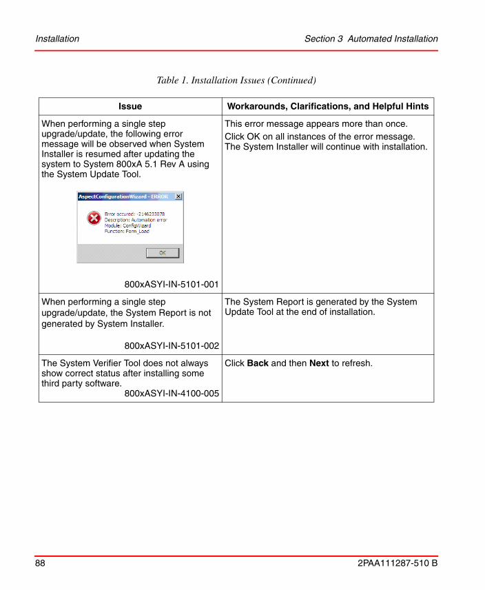
Installation Section 3 Automated Installation
88 2PAA111287-510 B
When performing a single step upgrade/update, the following error message will be observed when System Installer is resumed after updating the system to System 800xA 5.1 Rev A using the System Update Tool.
800xASYI-IN-5101-001
This error message appears more than once. Click OK on all instances of the error message. The System Installer will continue with installation.
When performing a single step upgrade/update, the System Report is not generated by System Installer.
800xASYI-IN-5101-002
The System Report is generated by the System Update Tool at the end of installation.
The System Verifier Tool does not always show correct status after installing some third party software.
800xASYI-IN-4100-005
Click Back and then Next to refresh.
Table 1. Installation Issues (Continued)
Issue Workarounds, Clarifications, and Helpful Hints

Section 3 Automated Installation Installation
2PAA111287-510 B 89
Installing Secondary Domain Controller asks for user account.
800xASYI-IN-4100-006
When installing the Secondary Domain Controller with the help of the System Installer you get a dialog with a red cross and the text:
you must type a user account name.
Enter a valid administrator account and password for that node, normally the one used when installing Windows on that node. Subsequently a dialog box asking to enter a restore user password. Enter the restore user password and keep it in a safe place. All other questions can be left with their default values.
When using the System Planner to plan a larger system with many system options, the System Planner may appear hung when it is calculating the internal dependencies. This can also happen if you are moving backwards in the System Planner after having finished defining the system. For a system with 40 to 50 nodes it may take up to several hours.
800xASYI-IN-4100-007
No workaround exists for this issue.
Not all node types can have clients combined to them.
800xASYI-IN-5000-005
In System Planner there are some Node types where it is not possible to select Client in this node. This is not a problem as the Client functionality is always installed on all nodes. Do not install the extra Client Setup Packages that are generated.
Cannot restart the System Installer using the DVD Autolaunch screen.
800xASYI-IN-5000-007
If a restart of the System Installer is needed after having started it, close the System Installer and DVD Autorun screen and start using:
Start > All Programs > Industrial IT 800xA > System > System Installer > Resume Install & Setup of this node.
Table 1. Installation Issues (Continued)
Issue Workarounds, Clarifications, and Helpful Hints

Installation Section 3 Automated Installation
90 2PAA111287-510 B
Cannot start Upgrade Wizard to collect information from a running system.
800xASYI-IN-5000-008
If the following message appears:
No Aspect System is created or it is stopped. Please start the System before running the Wizard.Press OK to exit the System Collection Wizard.
and the system is running, the problem is that a helper application, ppahelper.dll failed to register.
To register this application type in Start Menu -> Launch:
regsvr32 <path to helper application>\ppahelper.dll.
Normally the path to the application is when starting from DVD:
<DVD Driveletter>:\System Installer\Installation Tools\Upgrade
Installation of software has in some cases failed at the end, with a few software products remaining to be installed.
800xASYI-IN-5010-004
If the installation fails with an error indicating Installer not responding, out of memory, or exits System Installer, close the error, cancel the stopped installation, and restart the installation using:
Start > All Programs > Industrial IT 800xA > System > System Installer > Resume Install & Setup of this node.
In some cases, the Harmony Connectivity Server and Harmony Configuration Server will not be recognized during upgrade of a system with 800xA for Harmony installed.
NOTE: This is only an issue when upgrading from 800xA 4.1 to 800xA 5.1.
800xASYI-IN-5020-005
Re-install the 800xA for Harmony System Verify Helper.exe on the Aspect Server, Harmony Configuration Server, and the node on which Prepare System for Upgrade is run.
Table 1. Installation Issues (Continued)
Issue Workarounds, Clarifications, and Helpful Hints
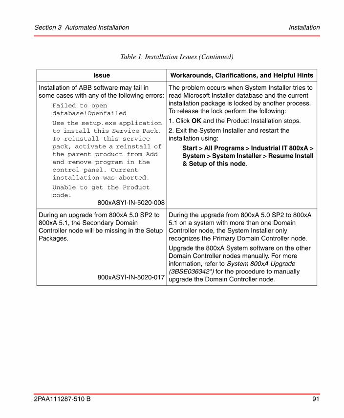
Section 3 Automated Installation Installation
2PAA111287-510 B 91
Installation of ABB software may fail in some cases with any of the following errors:
Failed to open database!Openfailed
Use the setup.exe application to install this Service Pack. To reinstall this service pack, activate a reinstall of the parent product from Add and remove program in the control panel. Current installation was aborted.
Unable to get the Product code.
800xASYI-IN-5020-008
The problem occurs when System Installer tries to read Microsoft Installer database and the current installation package is locked by another process. To release the lock perform the following:
1. Click OK and the Product Installation stops.
2. Exit the System Installer and restart the installation using:
Start > All Programs > Industrial IT 800xA > System > System Installer > Resume Install & Setup of this node.
During an upgrade from 800xA 5.0 SP2 to 800xA 5.1, the Secondary Domain Controller node will be missing in the Setup Packages.
800xASYI-IN-5020-017
During the upgrade from 800xA 5.0 SP2 to 800xA 5.1 on a system with more than one Domain Controller node, the System Installer only recognizes the Primary Domain Controller node.
Upgrade the 800xA System software on the other Domain Controller nodes manually. For more information, refer to System 800xA Upgrade (3BSE036342*) for the procedure to manually upgrade the Domain Controller node.
Table 1. Installation Issues (Continued)
Issue Workarounds, Clarifications, and Helpful Hints
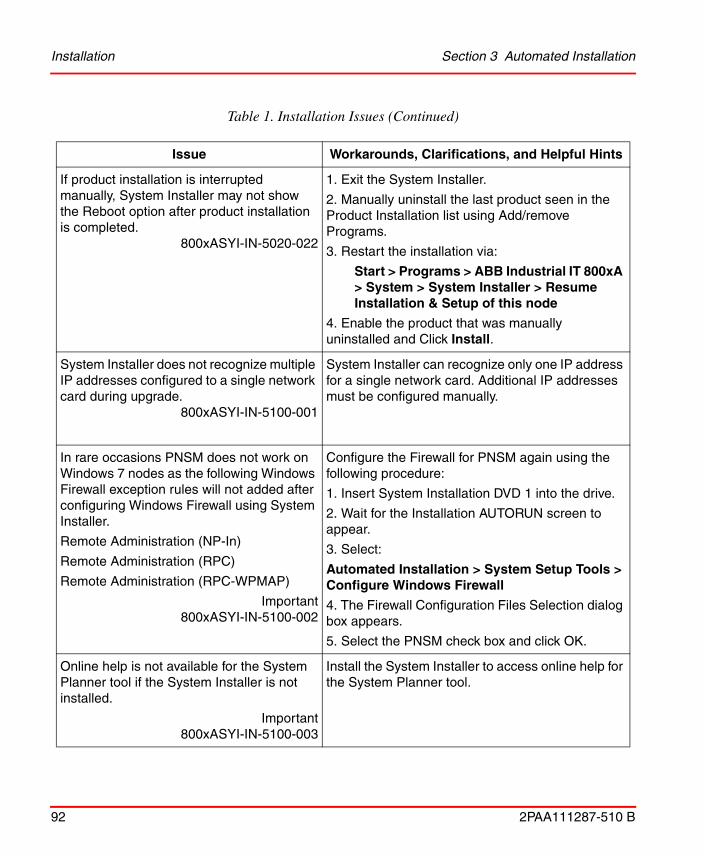
Installation Section 3 Automated Installation
92 2PAA111287-510 B
If product installation is interrupted manually, System Installer may not show the Reboot option after product installation is completed.
800xASYI-IN-5020-022
1. Exit the System Installer.
2. Manually uninstall the last product seen in the Product Installation list using Add/remove Programs.
3. Restart the installation via:
Start > Programs > ABB Industrial IT 800xA > System > System Installer > Resume Installation & Setup of this node
4. Enable the product that was manually uninstalled and Click Install.
System Installer does not recognize multiple IP addresses configured to a single network card during upgrade.
800xASYI-IN-5100-001
System Installer can recognize only one IP address for a single network card. Additional IP addresses must be configured manually.
In rare occasions PNSM does not work on Windows 7 nodes as the following Windows Firewall exception rules will not added after configuring Windows Firewall using System Installer.
Remote Administration (NP-In)
Remote Administration (RPC)
Remote Administration (RPC-WPMAP)
Important800xASYI-IN-5100-002
Configure the Firewall for PNSM again using the following procedure:
1. Insert System Installation DVD 1 into the drive.
2. Wait for the Installation AUTORUN screen to appear.
3. Select:
Automated Installation > System Setup Tools > Configure Windows Firewall
4. The Firewall Configuration Files Selection dialog box appears.
5. Select the PNSM check box and click OK.
Online help is not available for the System Planner tool if the System Installer is not installed.
Important800xASYI-IN-5100-003
Install the System Installer to access online help for the System Planner tool.
Table 1. Installation Issues (Continued)
Issue Workarounds, Clarifications, and Helpful Hints
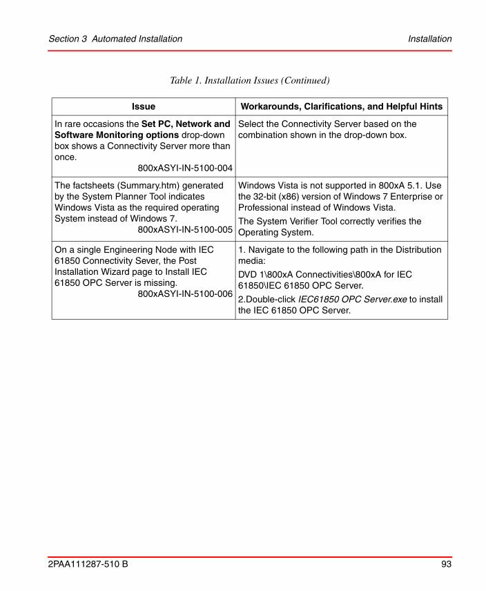
Section 3 Automated Installation Installation
2PAA111287-510 B 93
In rare occasions the Set PC, Network and Software Monitoring options drop-down box shows a Connectivity Server more than once.
800xASYI-IN-5100-004
Select the Connectivity Server based on the combination shown in the drop-down box.
The factsheets (Summary.htm) generated by the System Planner Tool indicates Windows Vista as the required operating System instead of Windows 7.
800xASYI-IN-5100-005
Windows Vista is not supported in 800xA 5.1. Use the 32-bit (x86) version of Windows 7 Enterprise or Professional instead of Windows Vista.
The System Verifier Tool correctly verifies the Operating System.
On a single Engineering Node with IEC 61850 Connectivity Sever, the Post Installation Wizard page to Install IEC 61850 OPC Server is missing.
800xASYI-IN-5100-006
1. Navigate to the following path in the Distribution media:
DVD 1\800xA Connectivities\800xA for IEC 61850\IEC 61850 OPC Server.
2.Double-click IEC61850 OPC Server.exe to install the IEC 61850 OPC Server.
Table 1. Installation Issues (Continued)
Issue Workarounds, Clarifications, and Helpful Hints

Installation Section 3 Automated Installation
94 2PAA111287-510 B

2PAA111287-510 B 95
Section 4 Base System
Known ProblemsThis section details the Known Problems for the Base system that exist in the system at the time of release.
Installation
Table 2 lists issues that may exist and affect the installation and upgrade of the system or product at time of release. Workarounds, clarifications, or helpful hints have been provided for each issue wherever possible.
Table 2. Installation Issues
Issue Workarounds, Clarifications, and Helpful Hints
PPA Services on the node are not started correctly when rebooted after installation using System Update Tool (SUT).
800xASYS-IN-5102-001
Check the Configuration Wizard log. If it displays the message Error - One or more of the supplied accounts does not match the accounts in the domain server, then rerun the System Software User Setting in the Configuration Wizard.
For more information, refer to System 800xA Tools (2PAA101888*).

Installation Section 4 Base System
96 2PAA111287-510 B
Avoid running the System Installer tool for Firewall Configuration to apply rules for System 800xA more than once. This may create multiple rule entries. The system maintenance will be complicated if there are multiple instances of the same firewall rules.
If only 800xA software is installed on a node, it is possible to configure the Windows Firewall multiple times by first Restoring the Default Policy and then applying 800xA rules using the System Installer tool for Firewall Configuration.
If any other software is installed on the 800xA node, for example, an Antivirus software, restoring to the "Default Policy" will erase the rules added by this additional software to the Windows Firewall.
NOTE: Avoid running the System Installer tool for Firewall Configuration to apply rules for System 800xA more than once. However, as an exception refer to the known problem, 800xASYI-IN-5100-002 related to PC, Network and Software Monitoring in Automated Installation.
Important800xASYS-IN-5100-013
Use one of the following methods to handle this issue:
1) Export the current Firewall policy after installation and any subsequent configuration change so that backup files are available for restore if required.
2) Manually reapply the Windows Firewall rules for software other than 800xA software if the Default Policy is restored and 800xA rules are reapplied using System Installer tool for Firewall Configuration.
Table 2. Installation Issues (Continued)
Issue Workarounds, Clarifications, and Helpful Hints

Section 4 Base System Administration
2PAA111287-510 B 97
Administration
Table 3 lists the issues that may exist and affect administration at time of release including user, node, and service structure related problems. Workarounds, clarifications, or helpful hints have been provided for each issue wherever possible.
During manual installation of 800xA software “This Program might not have installed correctly” notification from the Program Compatibility Assistance (PCA) Service Window can appear.
The PCA window will not appear if the product is installed with the System Update Tool (SUT).
800xASYS-IN-5101-001
Click on the Second Option “This program installed correctly”.
Table 3. Administration Issues
Issue Workarounds, Clarifications, and Helpful Hints
System Engineers are not allowed to log on locally on combined Domain Controller/Aspect Server.
Important800xASYS-AD-5100-006
In Windows Server 2008, domain users are normally not allowed to log on locally on domain controllers. This may cause problems for System Engineers in a system with a combined Domain Controller Aspect Server.
Users or groups will be able to log on locally to a domain controller if the domain administrator adds them to the policy "Allow log on locally" in "Computer Configuration\Windows Settings\Security Settings\Local Policies\User Right Assignment" on the Domain Controller Group Policy.
Table 2. Installation Issues (Continued)
Issue Workarounds, Clarifications, and Helpful Hints

Administration Section 4 Base System
98 2PAA111287-510 B
800xA Device Management FOUNDATION Fieldbus 5.1 does not support Multiple Disc function.
Important800xASYS-AD-5100-011
No workaround exists for this issue.
When using the System Configuration Console to change the System Directory Configuration the following restrictions apply for the service 'FFDataStorageAndDistribution':
• Do not change the Storage Directory to Server Data 2
• Do not change the mapping of variable Server Data to any other disc or directory
There will be an unexpected System Alarm generated when any Service Provider is not in operational state.
System Alarms like the following can appear:
“Service Provider X on Y operational” even though the service provider has been operational all the time.
800xASYS-AD-5000-002
A Service provider is operational when it is in the state Service or Standby.
There are however some situations where system alarms that were not expected might appear:
• When a server is restarted in a redundant system, Service Providers on other servers might enter Synchronizing state and where System Alarms are generated.
• When an Aspect Server is disconnected completely from the network, System Alarms for Service Providers on other servers might appear when the server is reconnected. These alarms are generated because the disconnected Aspect Server lost contact with other providers in the system. The alarms do not necessarily mean that the Service Providers were down.
After a node has been added to or removed using the Configuration Wizard, the node may not be visible in the System Status viewer.
Important800xASYS-AD-5000-044
It is recommended to restart all nodes in a system after a node has been added to or removed using the Configuration Wizard.
Table 3. Administration Issues (Continued)
Issue Workarounds, Clarifications, and Helpful Hints
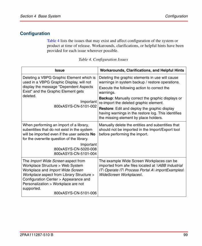
Section 4 Base System Configuration
2PAA111287-510 B 99
Configuration
Table 4 lists the issues that may exist and affect configuration of the system or product at time of release. Workarounds, clarifications, or helpful hints have been provided for each issue wherever possible.
Table 4. Configuration Issues
Issue Workarounds, Clarifications, and Helpful Hints
Deleting a VBPG Graphic Element which is used in a VBPG Graphic Display, will not display the message "Dependent Aspects Exist" and the Graphic Element gets deleted.
Important800xASYS-CN-5101-002
Deleting the graphic elements in use will cause warnings in system backup / restore operations.
Execute the following action to correct the warnings.
Backup: Manually correct the graphic displays or re-import the deleted graphic element.
Restore: Edit and deploy the graphic display having warnings in the restore log. This identifies the missing element by place holders.
When performing an import of a library, subentities that do not exist in the system will be imported even if the user selects No for the overwrite question of the library.
Important800xASYS-CN-5020-008800xASYS-CN-5101-004
Manually delete the entities and subentities that should not be imported in the Import/Export tool before performing the import.
The Import Wide Screen aspect from Workplace Structure > Web System Workplace and Import Wide Screen Workplace aspect from Library Structure > Configuration Center > Appearance and Personalization > Workplace are not supported.
800xASYS-CN-5101-006
The example Wide Screen Workplaces can be imported from afw files located at \\ABB Industrial IT\ Operate IT\ Process Portal A\ importExamples\ WideScreen Workplaces\.

Operation Section 4 Base System
100 2PAA111287-510 B
Operation
Table 5 lists the issues that may exist and affect operation of the system or product at time of release. Workarounds, clarifications, or helpful hints have been provided for each issue wherever possible.
Connecting a node to a new restored system or rebooting a node can take a long time if you have a lot of servers in the system and they are not up and running.
800xASYS-CN-5010-017
Ensure that all servers are up and running prior to connecting the clients.
During network disturbances the System Status Viewer can show wrong status for services when monitoring the Service Structure, even if the system is working correctly.
The Tray icon can also show the wrong status in this situation.
Important800xASYS-CN-5000-018
When the network is stable again bring up a new System Status Viewer.
Table 5. Operational Issues
Issue Workarounds, Clarifications, and Helpful Hints
In 1oo2 redundant systems, client nodes with affinity set to the non-master Aspect Server might lose the ability to launch new workplaces or operate from existing workplaces when the Aspect Servers are reconnected after being disconnected due to network failure.
Important800xASYS-OL-5101-005
Restart the non-master Aspect Server when both Aspect Servers are running and in service state. When the non-master Aspect Server is running in service state, restart the clients connected to the newly restarted Aspect Server.
Table 4. Configuration Issues (Continued)
Issue Workarounds, Clarifications, and Helpful Hints

Section 4 Base System Operation
2PAA111287-510 B 101
Engineering tools like Control Builder M, IO Allocation Tool, and Bulk Data Manager opens in the background when launched from the Workplace application.
Important800xASYS-OL-5100-010
Modify the windows registry setting "ForegroundLockTimeout" located at HKCU\Control Panel\Desktop to “0”. The default value is '200000' (hex 0x00030d40). This setting will cause all applications to be launched in the foreground.
Note: It is recommended to perform the setting only on Engineering Client nodes. This is a per user setting and requires a restart of the machine.
When performing a backup, the following error occurs (displayed in the backup log).
[Warning] Internal Error. Aspect = Inform IT Calculations:IT Faceplate Element HRESULT = 0x8abb003a E_AFW_FSD_NO_ITEM(0x8abb003a) This file set is unknown to the server.
[Error] Internal Error. Aspect = Inform IT Calculations:IT Faceplate Element HRESULT = 0x8abb003a E_AFW_FSD_NO_ITEM(0x8abb003a) This file set is unknown to the server.
Important800xASYS-OL-5100-012
The aspect needs to be re-imported before performing the backup again.
To do so, import the aspect "IT Faceplate Element" in the afw file "2WITES_VB.AFW" under the folder:
C:\ Program Files\ ABB Industrial IT\ Optimize IT\ PC, Network and Software Monitoring\ VBGraphicsExtension\ Import.
Engineering tools, like the Import/Export tool or the Deploy tool can get more contents than expected when the include dependencies option is used.
Important800xASYS-OL-5010-013
When the include dependencies option is used, be sure to check the contents before the operation is performed, i.e. before pushing the Deploy button etc. For Import/Export it is also recommended to check the file on what actually got exported.
Another solution is to include dependencies manually from the dependency list (not using the include dependencies option), i.e. right click on a dependent item and select Add item for each item.
Table 5. Operational Issues (Continued)
Issue Workarounds, Clarifications, and Helpful Hints
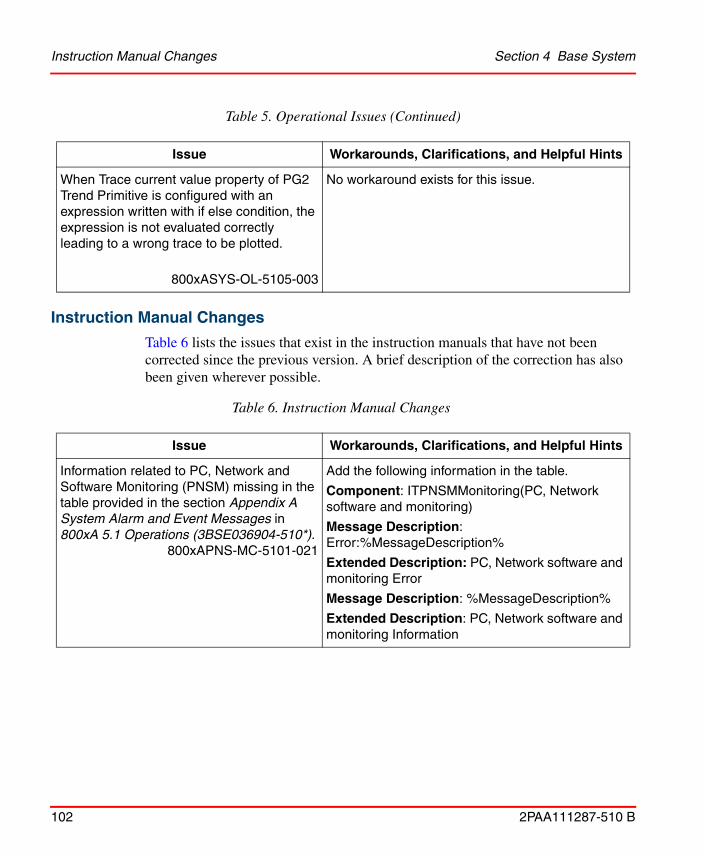
Instruction Manual Changes Section 4 Base System
102 2PAA111287-510 B
Instruction Manual Changes
Table 6 lists the issues that exist in the instruction manuals that have not been corrected since the previous version. A brief description of the correction has also been given wherever possible.
When Trace current value property of PG2 Trend Primitive is configured with an expression written with if else condition, the expression is not evaluated correctly leading to a wrong trace to be plotted.
800xASYS-OL-5105-003
No workaround exists for this issue.
Table 6. Instruction Manual Changes
Issue Workarounds, Clarifications, and Helpful Hints
Information related to PC, Network and Software Monitoring (PNSM) missing in the table provided in the section Appendix A System Alarm and Event Messages in 800xA 5.1 Operations (3BSE036904-510*).
800xAPNS-MC-5101-021
Add the following information in the table.
Component: ITPNSMMonitoring(PC, Network software and monitoring)
Message Description: Error:%MessageDescription%
Extended Description: PC, Network software and monitoring Error
Message Description: %MessageDescription%
Extended Description: PC, Network software and monitoring Information
Table 5. Operational Issues (Continued)
Issue Workarounds, Clarifications, and Helpful Hints

Section 4 Base System IPsec Configuration Tool
2PAA111287-510 B 103
IPsec Configuration ToolThis section details the Known Problems for the IPsec Configuration Tool that exist in the system at the time of release.
Configuration
Table 7. Configuration Issues
Issue Workarounds, Clarifications, and Helpful Hints
When IPsec is enabled on System 800xA 5.1 Rev B or later versions, the Batch client loses communication with the Batch server and goes offline.
800xAIPS-CN-5110-001
In the IPsec Configuration Tool:
• when performing a new configuration, select the Add New Rule option
• when editing an existing configuration, select User Defined Protocol option
and add the following exemption:
Subnet or IP address: Provide the Subnet of client server network, for example, 172.16.4.0/22
Protocol (UDP or TCP): UDP
Port on node in the 800xA Domain: any
Port on node outside the 800xA Domain: 50061
If redundant client server networks are used, add individual exemptions for each network.

Configuration Section 4 Base System
104 2PAA111287-510 B

2PAA111287-510 B 105
Section 5 System Services
Known ProblemsThis section details the Known Problems for the System Services that exist in the system at the time of release.
Central Licensing ServiceTable 8 lists the operational issues that may exist and affect the system or product at time of release. Workarounds, clarifications, or helpful hints have been provided for each issue wherever possible.
Table 8. Operational Issues
Issue Workarounds, Clarifications, and Helpful Hints
The License Usage Aspect in the system is not environment aware. This will generate differences in the environment differences tool.
800xASRV-OL-5100-010
Ignore this error as this would not impact the Central Licensing Service functionality.
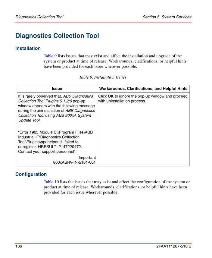
Diagnostics Collection Tool Section 5 System Services
106 2PAA111287-510 B
Diagnostics Collection Tool
Installation
Table 9 lists issues that may exist and affect the installation and upgrade of the system or product at time of release. Workarounds, clarifications, or helpful hints have been provided for each issue wherever possible.
Configuration
Table 10 lists the issues that may exist and affect the configuration of the system or product at time of release. Workarounds, clarifications, or helpful hints have been provided for each issue wherever possible.
Table 9. Installation Issues
Issue Workarounds, Clarifications, and Helpful Hints
It is rarely observed that, ABB Diagnostics Collection Tool Plugins 5.1.2/0 pop-up window appears with the following message during the uninstallation of ABB Diagnostics Collection Tool using ABB 800xA System Update Tool.
“Error 1905.Module C:\Program Files\ABB Industrial IT\Diagnostics Collection Tool\Plugins\ppahelper.dll failed to unregister. HRESULT -2147220472. Contact your support personnel”.
Important800xASRV-IN-5101-001
Click OK to ignore the pop-up window and proceed with uninstallation process.

Section 5 System Services Operation
2PAA111287-510 B 107
Operation
Table 11 lists the issues that may exist and affect the operation of the system or product at time of release. Workarounds, clarifications, or helpful hints have been provided for each issue wherever possible.
Table 10. Configuration Issues
Issue Workarounds, Clarifications, and Helpful Hints
It might not be possible to perform Collect, Explore or Analyze Data in case of the error "Error: Failed to contact Node Interrogator".
800xASRV-CN-5020-007
This error indicates that Node Interrogator Service is not running. To start this service:
1. Select ABB Node Interrogator service in Control Panel > Administrative Tools > Services.
2. Select Start from Action menu. This starts the Node Interrogator service.
3. Re-open Diagnostics Collection Tool.

Operation Section 5 System Services
108 2PAA111287-510 B
Table 11. Operational Issues
Issue Workarounds, Clarifications, and Helpful Hints
It is rarely observed that the collection or download does not complete after several hours for large Process dumps or WER dumps from nodes in the network.
Important800xASRV-OL-5100-002
Close the collection or download.
Ensure to collect dumps for less number of processes using User Dump Plug-in.
Use specific date option in WER Plug-in to collect dumps for a specific period or date.

Section 5 System Services Instruction Manual Changes
2PAA111287-510 B 109
Instruction Manual Changes
Table 12 lists the issues that exist in the instruction manuals that have not been corrected since the previous version. Workarounds, clarifications, or helpful hints have been provided for each issue wherever possible.
While using the DCT, it is observed that the Node Interrogator Service is gradually utilizing the memory and there by resulting in System.OutOfMemoryException.
800xADCT-OL-5110-006
Node Interrogator service has to be restarted.
To restart:
1. Select ABB Node Interrogator service in Control
Panel > Administrative Tools > Services.
2. Select Restart from the Action menu. This restarts the Node Interrogator service.
3. Re-open the Diagnostics Collection Tool.
Collect Software Consistency Data tool fails to collect data from 800xA nodes. Typically the failure happens in a 800xA system having more than 20 nodes, where data collection can fail after any node.
The following error messages are displayed in the Collecting Software Consistency Data window:
Exception of type 'System.OutOfMemoryException' was thrown
(or)
The server did not provide a meaningful reply; this might be caused by a contract mismatch, a premature session shutdown, or an internal server error
Important800xADCT-OL-5110-001
The data collection failure happens due to large size data.
Close the Collect Software Consistency Data tool and follow the steps below to modify the Software Consistency Data configuration and run the collection.
1 Open Collection Tool, and select the following plug-ins:- 800xA -> System->System Report- Standard -> Task Manager, Installed Software and Registry Dump
2 Press Ctrl+Shift+S.
3 Click Yes in the Save Command File For Software Consistency window to proceed.
4 Close Collection Tool and run Collect Software Consistency Data.
5
Table 11. Operational Issues (Continued)
Issue Workarounds, Clarifications, and Helpful Hints

SMS and Email Messaging Section 5 System Services
110 2PAA111287-510 B
SMS and Email Messaging
Structured Data Logger
Configuration
Table 13 lists the issues that may exist and affect the configuration of the system or product at time of release. Workarounds, clarifications, or helpful hints have been provided for each issue wherever possible.
Table 12. Instructional Manual Changes
Issue Workarounds, Clarifications, and Helpful Hints
System 800xA Performance Data plug-in is currently documented under standard plug-ins.
800xASRV-MC-5100-003
Instead, this plug-in should to be listed under System 800xA plug-ins in the Online help and in the System 800xA 5.1 Tools (2PAA101888*) manual accordingly.
System 800xA Performance Data plug-in, when selected on a node, the following message appears:
System 800xA Performance Data plug-in can be selected only for one node.
It is not advised to combine this plug-in to be selected with any other plug-in.
Do not run collection for this plug-in, concurrently from any other machine.
This message is not documented in System 800xA 5.1 Tools (2PAA101888*).
800xASRV-MC-5104-004
Follow the instructions stated in the message and proceed further.

Section 5 System Services Configuration
2PAA111287-510 B 111
Table 13. Configuration Issues
Issue Workarounds, Clarifications and Helpful Hints
An export (with dependencies) of SDL Log aspects does not automatically include SDL Log Type aspects.
800xASDL-CN-5020-001
Manually export the SDL Log Type aspects used by the SDL Log aspect.

Configuration Section 5 System Services
112 2PAA111287-510 B
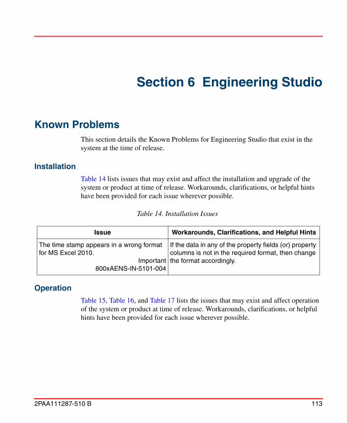
2PAA111287-510 B 113
Section 6 Engineering Studio
Known ProblemsThis section details the Known Problems for Engineering Studio that exist in the system at the time of release.
Installation
Table 14 lists issues that may exist and affect the installation and upgrade of the system or product at time of release. Workarounds, clarifications, or helpful hints have been provided for each issue wherever possible.
Operation
Table 15, Table 16, and Table 17 lists the issues that may exist and affect operation of the system or product at time of release. Workarounds, clarifications, or helpful hints have been provided for each issue wherever possible.
Table 14. Installation Issues
Issue Workarounds, Clarifications, and Helpful Hints
The time stamp appears in a wrong format for MS Excel 2010.
Important800xAENS-IN-5101-004
If the data in any of the property fields (or) property columns is not in the required format, then change the format accordingly.

Operation Section 6 Engineering Studio
114 2PAA111287-510 B
Table 15. Function Designer, Operational Issues
Issue Workarounds, Clarifications, and Helpful Hints
In some instances, allocation of CBM signal of Function Diagram to PROFIBUS devices, may show incorrect traffic light.
Important800xAENS-OL-5104-023
No workaround exists for this issue.
In some instances, string connected to a port of user defined Function Block, may not be passed to CBM on generation of Configuration Data.
800xAENS-OL-5104-010
No workaround exists for this issue.
In some instances, allocation of CBM signal of Function Diagram to controller and/or on generating Configuration Data, may result in the following warning message:
Application “XXXX” is not connected to any controller, Transaction committed.
Important800xAENS-OL-5104-030
No workaround exists for this issue.
In a Function Diagram width of blocks like Control Modules is adjusted to suit for text scaling when opening with different screen resolutions. This may result in truncation of Name and Description of blocks.
Important
800xAENS-OL-5104-019
Re-write the Name and Description using Bulk Data Manager.

Section 6 Engineering Studio Operation
2PAA111287-510 B 115
Connecting MBRead output port of AnyType datatype, to an input port of Control Module/ Function Block of any datatype, results in error on generating Configuration Data.
Important800xAENS-OL-5104-025
No workaround exists for this issue.
When a Function diagram is inserted under another object, and if a delete operation is performed on it. This may result in deletion of the source Function Diagram.
800xAENS-OL-5104-006
No workaround exists for this issue.
If there are multiple blocks in a Function Diagram with same port name and datatype, and if variables are created on these ports by a right-click on the port, then the variables are assigned a name same as the port name, it may result in multiple invocation of the variable.
Important800xAENS-OL-5104-007
No workaround exists for this issue.
Forcing a CBM signal in a Function Diagram is not possible if the CBM signal name contains hyphen (-) in it.
Important800xAENS-OL-5104-008
No workaround exists for this issue.
Table 15. Function Designer, Operational Issues (Continued)
Issue Workarounds, Clarifications, and Helpful Hints

Operation Section 6 Engineering Studio
116 2PAA111287-510 B
On repetitive opening of a Function Diagram that is pasted using Paste Special function, may result in loss of Function blocks, CBM signals etc. in the Function Diagram.
Product Bulletin ID: 9ARD134783-213
Important800xAENS-OL-5104-022
Do not use Paste Special for copy-paste of Function Diagrams.
Graphical changes in a Function Diagram, such as, change in connected parameter, routing changes and so on, that are done from one 800xA node, may not be updated when the same Function Diagram is opened on another 800xA node through the Function Aspect of it's child object.
Product Bulletin ID: 9ARD134783-214
Important800xAENS-OL-5104-032
One of the following workarounds can be used:
• Restart the workplace and then open the Function Diagram.
• Open the parent Function Diagram from its Function aspect instead of the child object.
• Keep the Function Diagram open while doing a change on the same Function Diagram from another node.
Revert operation in LEG does not clean up production environment from the Function Diagram.
This is because, the Function aspect is added in the Function Blocks of the user defined library. The library is then used in the Function Diagram and the application is sent through LEG.
800xAENS-OL-5102-011
Changes to User Defined libraries (Adding Function aspect) must be done in the Production Environment only while using LEG for Function diagrams.
In some instances, Windows Event Viewer displays the Side by Side error.
800xAENS-OL-5102-013
This error message can be ignored.
Table 15. Function Designer, Operational Issues (Continued)
Issue Workarounds, Clarifications, and Helpful Hints

Section 6 Engineering Studio Operation
2PAA111287-510 B 117
Consider a Function Diagram containing a page connector. If the diagram is copy / pasted and the page connector is renamed in the copied diagram, then the position and size of the page connector changes with respect to the original diagram.
Important800xAENS-OL-5101-005
No workaround exists for this issue.
Copy and paste the default AND (bool) block in a Transition of a sequential diagram. Create a logic using the pasted AND block. Save and close the diagram. While reopening the diagram, the connections to the pasted AND block are lost.
Important800xAENS-OL-5101-009
Add a new AND (bool) block using Insert menu.
The information about external references to Communication Variable is not available in the Function Diagram, for the scenario explained below:
Communication Variable (CV1) is declared in a Function Diagram and this diagram is allocated to an application, which also contains Single Control Modules/Programs with the same communication variable (CV1). In this case, the communication variable in the diagram does not indicate the external reference information.
Important800xAENS-OL-5100-021
This does not affect the functionality of Communication Variables.
Table 15. Function Designer, Operational Issues (Continued)
Issue Workarounds, Clarifications, and Helpful Hints
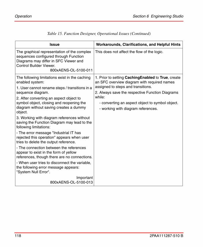
Operation Section 6 Engineering Studio
118 2PAA111287-510 B
The graphical representation of the complex sequences configured through Function Diagrams may differ in SFC Viewer and Control Builder Viewer.
800xAENS-OL-5100-011
This does not affect the flow of the logic.
The following limitations exist in the caching enabled system:
1. User cannot rename steps / transitions in a sequence diagram.
2. After converting an aspect object to symbol object, closing and reopening the diagram without saving creates a dummy object.
3. Working with diagram references without saving the Function Diagram may lead to the following limitations:
- The error message "Industrial IT has rejected this operation" appears when user tries to delete the output reference.
- The connection between the references appear to exist in the form of yellow references, though there are no connections.
- When user tries to disconnect the variable, the following error message appears: "System Null Error".
Important800xAENS-OL-5100-013
1. Prior to setting CachingEnabled to True, create an SFC overview diagram with required names assigned to steps and transitions.
2. Always save the respective Function Diagrams while:
- converting an aspect object to symbol object.
- working with diagram references.
Table 15. Function Designer, Operational Issues (Continued)
Issue Workarounds, Clarifications, and Helpful Hints
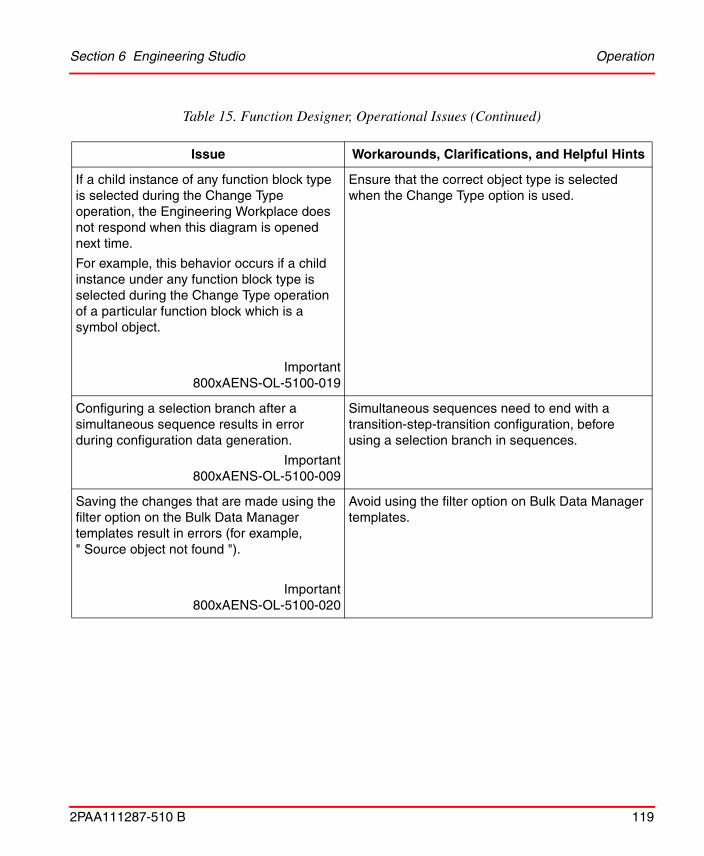
Section 6 Engineering Studio Operation
2PAA111287-510 B 119
If a child instance of any function block type is selected during the Change Type operation, the Engineering Workplace does not respond when this diagram is opened next time.
For example, this behavior occurs if a child instance under any function block type is selected during the Change Type operation of a particular function block which is a symbol object.
Important800xAENS-OL-5100-019
Ensure that the correct object type is selected when the Change Type option is used.
Configuring a selection branch after a simultaneous sequence results in error during configuration data generation.
Important800xAENS-OL-5100-009
Simultaneous sequences need to end with a transition-step-transition configuration, before using a selection branch in sequences.
Saving the changes that are made using the filter option on the Bulk Data Manager templates result in errors (for example, " Source object not found ").
Important800xAENS-OL-5100-020
Avoid using the filter option on Bulk Data Manager templates.
Table 15. Function Designer, Operational Issues (Continued)
Issue Workarounds, Clarifications, and Helpful Hints

Operation Section 6 Engineering Studio
120 2PAA111287-510 B
In some instances, while subscribing live data in the Function Diagrams, navigating from sender to receiver diagram and performing graphical changes by selecting group of objects leads the system to stop responding.
Important 800xAENS-OL-5100-004
While subscribing live data, do not perform any graphical changes by selecting group of objects in the Function Diagrams.
The diagram state indicated in the traffic light symbol of the status bar of the Function Designer window shows incorrect status ( ) while using Write Allocation into CBM from the IO Allocation dialog.
800xAENS-OL-5100-007
Regenerate configuration data after performing Write allocation to CBM from the IO Allocation dialog to obtain the correct diagram state in the traffic light symbol.
In a sequence block, if different actions in multiple steps are having the same name, they always point to the same action when ‘SFC Overview’ is used to navigate through the actions.
Important800xAENS-OL-5100-022
Ensure that unique action names are followed across a sequence.
Creation of several thousands of Function Diagrams using Bulk Data Manager may fail.
Bulk Data Manager progress bar may disappear while updating several hundred objects although the operation is in progress.
Important800xAENS-OL-5100-015
1. Set VarCrossRef_Include_DiagRef to False before performing any bulk operations.
For more information, refer to System 800xA Engineering Engineering Studio Function Designer (3BDS011224*).
2. If several thousands of Function Diagrams need to be created using Bulk Data Manager, then split the Function Diagrams into manageable quantities (less than thousands) and create them separately using Bulk Data Manager.
Table 15. Function Designer, Operational Issues (Continued)
Issue Workarounds, Clarifications, and Helpful Hints

Section 6 Engineering Studio Operation
2PAA111287-510 B 121
In the Function Diagram, copy / paste of an existing group of connected blocks with system functions and diagram references results in error messages during configuration data generation.
Important 800xAENS-OL-5100-010
Navigate to the specific errors and correct it manually.
User cannot change or repair Engineering Studio through Add or Remove Programs.
800xAENS-OL-5100-012
Uninstall Engineering Studio and reinstall it.
Table 15. Function Designer, Operational Issues (Continued)
Issue Workarounds, Clarifications, and Helpful Hints

Operation Section 6 Engineering Studio
122 2PAA111287-510 B
Function Diagrams linked through diagram references and opened in workbook mode may have the following issues.
Scenario 1:
1.Select either Subscribe for Live Data for Connected Output Ports or Subscribe for Live Data Output Ports for a Function Diagram.
2. Double-click and select the Diagram in the next tab and select either Subscribe for Live Data for Connected Output Ports or Subscribe for Live Data Output Ports.
The values are not displayed for the current Function Diagram.
Scenario 2:
Select either Subscribe for Live Data for Connected Output Ports or Subscribe for Live Data Output Ports for any page of a Function Diagram where the source page connector is available.
The color indication for the Boolean values is visible in the sink page connector though that specific page is not subscribed by the user.
Scenario 3:
Select Subscribe for Live Data for Connected Output Ports for the Function Diagram. The color indication for the inout ports of the Boolean datatype is not correctly displayed based on the value transferred between the ports.
Important800xAENS-OL-5100-018
Scenario 1:
In the specific Function Diagram, deselect and select Subscribe for Live Data for Connected Output Ports or Subscribe for Live Data Output Ports again to display the values.
Table 15. Function Designer, Operational Issues (Continued)
Issue Workarounds, Clarifications, and Helpful Hints

Section 6 Engineering Studio Operation
2PAA111287-510 B 123
Flipping through many Function Diagrams through the Preview pane of Engineering Workplace causes the Engineering Workplace to stop responding.
Important800xAENS-OL-5100-023
Avoid using the Preview pane while working with many function diagrams. If a number of diagrams need to be opened, open them in separate windows (In the Engineering Workplace, go to the Functional Structure, right-click the Function Diagram, and select Function).
Table 15. Function Designer, Operational Issues (Continued)
Issue Workarounds, Clarifications, and Helpful Hints

Operation Section 6 Engineering Studio
124 2PAA111287-510 B
In some instances, Function Designer and Control Builder M stop responding during configuration data generation when Control Builder M is online.
Important
800xAENS-OL-5100-016
1. Avoid performing configuration data generation while Control Builder M is in online mode.
2. In Control Builder M, always set system variable SaveColdRetainOnOfflineTransfer to False in the following path: Tools > Setup > Station > Application.
3. If Control Builder M has stopped responding, perform the following:
a. Open the Windows Task Manager and select the Processes tab.
b. Click Image Name to sort the column.
c. Select the controlbuilderpro.exe process.
d. Click End Process.
e. Click Yes in the Task Manager Warning dialog box to end the process.
f. Restart the workplace and regenerate configuration data for the specific Function Diagram.
Table 15. Function Designer, Operational Issues (Continued)
Issue Workarounds, Clarifications, and Helpful Hints

Section 6 Engineering Studio Operation
2PAA111287-510 B 125
If a modified Function Diagram is closed without saving, it will execute a consistency check once when the specific diagram is reopened. Depending on the amount of changes and the size of the diagram, this consistency check may take considerable time.
This behavior also occurs while working with large sized diagrams when the Insufficient memory error message appears.
Important 800xAENS-OL-5024-016
While working with large sized Function Diagrams or while performing large amount of changes, it is recommended to save the diagrams frequently.
Select the Normal Position checkbox in the CBM_SignalParameter aspect of a DIS signal. Allocate it to channel 12 of a DI830 device through the Write Allocation into CBM operation from the IO Allocation dialog. The Normal Position detail is not updated in Control Builder M.
Important800xAENS-OL-5024-004
Perform the following in Control Builder M after allocating DI830 device through the Write Allocation into CBM operation from the IO Allocation dialog:
1. Right-click DI830 and click Reservation.
2. Double-click DI830 and edit the value of the Normal Position attribute for channel 12.
3. Click Save.
In some rare instances, Function Designer online values are not displayed on diagram references in child diagrams.
800xAENS-OL-5024-020
Reopening the diagram will display the online values.
In some instances, cut paste of Sequence 2D across diagrams may result in inconsistency in sequence.
800xAENS-OL-5025-017
No workaround exists for this issue.
Table 15. Function Designer, Operational Issues (Continued)
Issue Workarounds, Clarifications, and Helpful Hints

Operation Section 6 Engineering Studio
126 2PAA111287-510 B
While inserting or editing the name for function block in the SCM based Function Diagram, text box with blue background is displayed.
800xAENS-OL-5103-001
Click outside the text box to view the edited text.
In Function Diagram editor, if two ports of same or different function block types / control module types with same data type, are connected directly without creating a variable, the resulted connection is not visible in Control Builder diagram editor.
800xAENS-OL-5103-005
Insert a variable of same data type and connect both the ports.
In a sequence step, if a diagram reference is connected to a variable of structure data type, logic is not transferred to the CBM.
800xAENS-OL-5103-002
No workaround exists for this issue.
When a Function Setting ConfigDataForSFC is set as true, on performing Configuration Data Generation, SFCXRefDataMapper aspect is created for all diagrams by default.
800xAENS-OL-5101-016
No workaround exists for this issue.
Table 15. Function Designer, Operational Issues (Continued)
Issue Workarounds, Clarifications, and Helpful Hints

Section 6 Engineering Studio Operation
2PAA111287-510 B 127
Copying a Function Diagram with internal connections sources leads to error. If the setting is set to Make new unique connection, sinks and sources are renamed and connected to the original source.
800xAENS-OL-5102-005
No workaround exists for this issue.
On using Paste Rename functionality for the Function Diagrams having diagram references with property “Keep connection to the source”, Engineering Workplace may stop responding.
Important800xAENS-OL-5104-034
No workaround exists for this issue.
Table 16. IO Allocation, Operational Issues
Issue Workarounds, Clarifications, and Helpful Hints
IO-Allocation of DP910 FI2P and DP910 FI2 F (S900) IO boards is not possible using IO Allocation tool. This is due to mis-match of datatype and number of channels in the board.
Important800xAENS-OL-5104-024
No workaround exists for this issue.
IO allocation tool stops responding when it is invoked from controller in Control Structure.
Important800xAENS-OL-5104-033
No workaround exists for this issue
Table 15. Function Designer, Operational Issues (Continued)
Issue Workarounds, Clarifications, and Helpful Hints

Operation Section 6 Engineering Studio
128 2PAA111287-510 B
Scaling of frequency value to process unit is set by the 'Min' & 'Max' values provided in the 'Properties' tab of pulse boards (e.g: DP820, DP840) in Control Builder M.
Users are unable to configure this through IO Allocation tool.
Important800xAENS-OL-5100-006
No workaround exists for this issue.
The min-max values and engineering unit details of the de-allocated variable are not getting cleared in CBM IO editor.
800xAENS-OL-5103-009
No workaround exists for this issue.
If some channels are connected to variables in Control Builder M and others are allocated through I/O allocation, this may lead to Inconsistency in generated data.
800xAENS-OL-5103-020
No workaround exists for this issue.
Table 16. IO Allocation, Operational Issues
Issue Workarounds, Clarifications, and Helpful Hints

Section 6 Engineering Studio Operation
2PAA111287-510 B 129
Table 17. Bulk Data Manager, Operational Issues
Issue Workarounds, Clarifications, and Helpful Hints
On opening BDM templates/sheets in Microsoft Excel 2013, BDM toolbar stops functioning.
Technical Description ID: 9ARD134783-207
Important800xAENS-OL-5104-036
Open Microsoft Excel 2013 using Advanced menu of Engineering Workplace.
Advanced -> Bulk Data Manager
Advanced -> Engineering Templates
In some instances, while working with BDM, with the selection of Min Path from the Advanced menu instead of Full Path, may cause MS-Excel to stop responding.
800xAENS-OL-5104-001
Use Full Path instead of Min Path from the Advanced menu of BDM.
In BDM template, the Function Diagrams aspect command Upload Init Vals does not work properly.
800xAENS-OL-5100-027
Upload the init Vals from Engineering Workplace
In some instances, for some specific Function Diagrams, BDM stops responding on using menu Aspect Commands ->Generate Configuration Data for a Function aspect.
800xAENS-OL-5102-002
No workaround exists for this issue.
In some instance, on performing Configuration Data Generation in BDM, following error message is displayed:
Identifier invalid or to long.800xAENS-OL-5102-004
No workaround exists for this issue.

Instructional Manual Changes Section 6 Engineering Studio
130 2PAA111287-510 B
Instructional Manual Changes
Table 19 lists the issues that exist in the instruction manuals that have not been corrected since the previous version. A brief description of the correction has also been given wherever possible.
Table 18. Script Manager, Operational Issues
Issue Workaround, Clarifications, and Helpful Hints
Attach Debugger icon is not functional in Script manager.
800xAENS-OL-5103-030
No workaround exists for this issue.
Table 19. Instructional Manual Changes
Issue Workaround, Clarifications, and Helpful Hints
On copy-paste of a Sequence/Sequence2D with multiple Steps/Transitions connected to single Transition/Step makes one or more connection links red and results in error.
Important800xAENS-MC-5104-008
Close and re-open the Function Diagram (or) delete the red colored connection link and reconnect manually.

2PAA111287-510 B 131
Section 7 AC 800M
IntroductionThis section provides information on safety and compatibility of the system. It also enumerates known problems encountered in the final testing of this product release.Where possible the document identifies workarounds that help overcome the problem. The section also contains additional notes that may be valuable to customers and service personnel working with the product.
SafetyFor a complete list of AC 800M safety related warnings, for this release, see System 800xA Safety AC 800M High Integrity Safety Manual (3BNP004865*).
For information on SIL (Safety Integrity Level) conformance according to IEC 61508 or other applicable safety standards, refer to the manual System 800xA Safety AC 800M High Integrity Safety Manual (3BNP004865*).
The term Control Builder refers to Control Builder M Professional.The term OPC Server refers to OPC Server for AC 800M.The term Modem refers to modems that are configured and controlled by a controller. It does not refer to modems that are transparent for the controller.The term Controller refers to a Process Automation (PA) Controller. If it is a High Integrity Controller, the text will say High Integrity or HI Controller.
In order to get the formal status of the safety certification of a 800xA Safety product (hardware and software components), refer to the latest version of the TÜV Certification Report, Annex 2, ABB Solutions Bank or ABB Library (3BSE054960).

Version Designation Section 7 AC 800M
132 2PAA111287-510 B
Safety Certification Status
Before a High Integrity controller can be put into operation, any NON-CERT marked High Integrity firmware in the controller must be replaced with TÜV certified counterparts.
It is mandatory for the user to verify that all 800xA Safety products used in a safety critical installation, are certified according to the applicable standards, before they are put into operation for production. If the used hardware or software versions are not yet listed in the latest available TÜV Certification Report, Annex 2, contact your local ABB sales representative or TÜV Süd Group (+49 8951903133), for further information.
Version Designation
Software
Control Software for AC 800M System Version 5.1 contains software support for the following products.
In order to get the formal status of the safety certification of a 800xA Safety product (hardware and software components), refer to the latest version of the TÜV Certification Report, Annex 2, ABB Solutions Bank or ABB Library (3BSE054960).
Table 20. Software Support
Released Software Version
Control Builder M Professional 5.1.0-3
AC 800M Connect (800xA for AC 800M) 5.1.0-3
Firmware for PM851/PM856/PM860 5.1.0-3
Firmware for PM861(A)/PM864(A)/PM865/PM866
5.1.0-3
Firmware for PM891 5.1.0-3
Firmware for PM865 in AC 800M HI 5.0.2/5
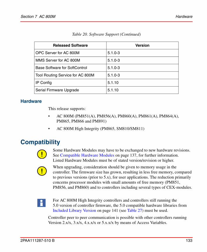
Section 7 AC 800M Hardware
2PAA111287-510 B 133
Hardware
This release supports:
• AC 800M (PM851(A), PM856(A), PM860(A), PM861(A), PM864(A), PM865, PM866 and PM891)
• AC 800M High Integrity (PM865, SM810/SM811)
Compatibility
Controller peer to peer communication is possible with other controllers running Version 2.x/x, 3.x/x, 4.x.x/x or 5.x.x/x by means of Access Variables.
OPC Server for AC 800M 5.1.0-3
MMS Server for AC 800M 5.1.0-3
Base Software for SoftControl 5.1.0-3
Tool Routing Service for AC 800M 5.1.0-3
IP Config 5.1.10
Serial Firmware Upgrade 5.1.10
Some Hardware Modules may have to be exchanged to new hardware revisions. See Compatible Hardware Modules on page 137, for further information. Listed Hardware Modules must be of stated version/revision or higher.
When upgrading, consideration should be given to memory usage in the controller. The firmware size has grown, resulting in less free memory, compared to previous versions (prior to 5.x), for user applications. The reduction primarily concerns processor modules with small amounts of free memory (PM851, PM856, and PM860) and to controllers including several types of CEX-modules.
For AC 800M High Integrity controllers and controllers still running the 5.0 version of controller firmware, the 5.0 compatible hardware libraries from Included Library Version on page 141 (see Table 27) must be used.
Table 20. Software Support (Continued)
Released Software Version

Supported Versions Section 7 AC 800M
134 2PAA111287-510 B
Supported Versions
Online Upgrade Paths
Redundant AC 800M controllers can be upgraded with new firmware versions online. Online upgrade is initiated from Control Builder by a 9-step wizard, that describes the complete upgrading process. For more information, refer to the Maintenance and Trouble-Shooting section in System 800xA Control AC 800M Configuration (3BSE035980*) manual.
Online upgrade is supported only from the controller versions listed in Table 21 and Table 22.
Table 21. Supported Online Upgrade Paths for Process Automation (PA) Controllers
Revision Release Date Remarks
Version 5.0.0/0 October 25, 2006 5.0
Version 5.0.0/1 March 15, 2007 5.0 RU1
Version 5.0.1/0 June, 2007 5.0 SP1
Version 5.0.1/1 December, 2007 5.0 SP1 RU1
Version 5.0.1/2 March, 2008 5.0 SP1 RU2
Version 5.0.2/0 August, 2008 5.0 SP2
Version 5.0.2/2 March, 2009 5.0 SP2 RU2
Version 5.0.2/3 September, 2009 5.0 SP2 RU3
Version 5.0.2/4 December, 2010 5.0 SP2 RU4
Version 5.0.2/5 October, 2011 5.0 SP2 RU5
Version 5.1.0/0 June, 2010 5.1
Version 5.1.0/1 May 2011 5.1 RU1
Version 5.1.0-2 December, 2012 5.1 RU2

Section 7 AC 800M Supported Versions
2PAA111287-510 B 135
Supported Versions for Coexistence of Controller Versions
Starting from Version 5 and installing newer versions of Control Builder and OPC Server does not require a controller upgrade. Controllers with different firmware versions can coexist in the same network, and newer versions of Control Builder and OPC Server can connect to controllers of older versions (not older than Version 5). All Control Builders and OPC Servers must be of the latest version in a running installation.
Coexistence is supported between the controller versions listed in Table 23 and Table 24.
Table 22. Supported Online Upgrade Paths for High Integrity (HI) Controllers
Revision Release Date Remarks
Version 5.0.2/5 October, 2011 5.0 SP2 RU5
Version 5.1.0-2(1) December, 2012 5.1 RU2
(1) Version 5.1.0-2 uses AC 800M High Integrity release from 5.0.2/5.
Table 23. Supported Versions for Coexistence of Process Automation (PA) Controllers
Revision Release Date Build No. Remarks
Version 5.0.0/0 October, 2006 5.0.11.61 5.0
Version 5.0.0/1 March, 2007 5.0.12.5 5.0 RU1
Version 5.0.1/0 July, 2007 5.0.1001.755.0.1001.76
5.0 SP1
Version 5.0.1/1 December, 2007 5.0.1004.14 5.0 SP1 RU1
Version 5.0.1/2 March, 2008 5.0.1005.4 5.0 SP1 RU2
Version 5.0.2/0 August, 2008 5.0.2004.52 5.0 SP2
Version 5.0.2/2 March, 2009 5.0.2008.29 5.0 SP2 RU2
Version 5.0.2/3 September, 2009 5.0.2010.17 5.0 SP2 RU3
Version 5.0.2/4 December, 2010 5.0.2410.26 5.0 SP2 RU4
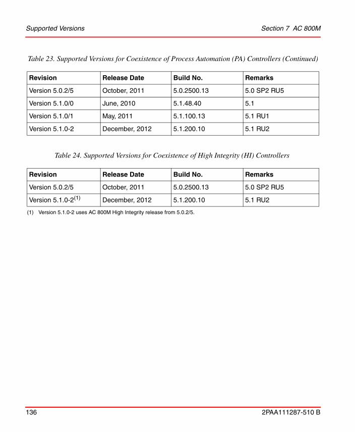
Supported Versions Section 7 AC 800M
136 2PAA111287-510 B
Version 5.0.2/5 October, 2011 5.0.2500.13 5.0 SP2 RU5
Version 5.1.0/0 June, 2010 5.1.48.40 5.1
Version 5.1.0/1 May, 2011 5.1.100.13 5.1 RU1
Version 5.1.0-2 December, 2012 5.1.200.10 5.1 RU2
Table 24. Supported Versions for Coexistence of High Integrity (HI) Controllers
Revision Release Date Build No. Remarks
Version 5.0.2/5 October, 2011 5.0.2500.13 5.0 SP2 RU5
Version 5.1.0-2(1)
(1) Version 5.1.0-2 uses AC 800M High Integrity release from 5.0.2/5.
December, 2012 5.1.200.10 5.1 RU2
Table 23. Supported Versions for Coexistence of Process Automation (PA) Controllers (Continued)
Revision Release Date Build No. Remarks

Section 7 AC 800M Compatible Hardware Modules
2PAA111287-510 B 137
Compatible Hardware ModulesThe Hardware Modules listed in Table 25 must be of the stated version/revision or higher.
Listed I/O Modules are included due to compatibility issues only. For some other I/O Modules there is a recommendation about firmware and hardware versions for other reasons. See other relevant documentation regarding such reasons.
Firmware in all Hardware Modules must be upgraded to the delivered version. See Compatible Firmware on page 141.
Table 25. Compatible Hardware Modules
Module Required Version Recommended Version
PM851 PR:A
PM851A PR:A
PM856 PR:A PR:F
PM856A PR:A
PM860 PR:B PR:H
PM860A PR:B
PM861(Singular)
PR:B PR:L
PM861(Redundant)
PR:B(1) PR:L
PM861A(Singular)
PR:B PR:C
PM861A(Redundant)
PR:B with FPGA 1.2/1
-or-
PR:C
PR:C(2)

Compatible Hardware Modules Section 7 AC 800M
138 2PAA111287-510 B
PM864 PR:B with FPGA 1.2/5
-or-
PR:C
PR:H
PM864A(Singular)
PR:B PR:C
PM864A(Redundant)
PR:B with FPGA 1.2/1
-or-
PR:C
PR:C(2)
PM865(Process Automation
Singular)
PR:C PR:D
PM865(Process Automation
Redundant)
PR:C with FPGA 2.0/0
-or-
PR:D
PR:D(3)
PM865(High Integrity)
PR:G
PM866 PR:B
PM891 PR:A
SM810 PR:C
SM811 PR:A
CI851 PR:A PR:H
CI852 PR:A PR:B
CI853 PR:C(4)
CI854 PR:B
Index 01.00
PR:G
Index 01.03(5)
Table 25. Compatible Hardware Modules (Continued)
Module Required Version Recommended Version

Section 7 AC 800M Compatible Hardware Modules
2PAA111287-510 B 139
CI854A PR:D
Index 02.05
CI855 PR:B PR:C(6)
CI856 PR:A PR:B(7)(8)
CI857 PR:B PR:C
CI858 PR:A
CI860 PR:C
Index 02.01
PR:H(9)
Index 04.00
CI865 PR:B
CI867 PR:A
CI868 PR:A
CI869 PR:D
CI871 PR:A
CI872 PR:B PR:D
CI873 PR:A
TB840 PR:J(10) PR:M
TB840A PR:A
DI830 PR: H(11) PR: K
DI831 PR: H(11) PR: K
DI885 PR:C
AI845 PR:F
AO845 PR:E PR:J
AO845A PR:A PR:C
Table 25. Compatible Hardware Modules (Continued)
Module Required Version Recommended Version

Compatible Hardware Modules Section 7 AC 800M
140 2PAA111287-510 B
DI880 PR:E PR:J
DO880 PR:F(12) PR:J
AI880A(13) PR:B PR:F
BC810 PR:C(14) PR:E
200-APB12 1.6
200-ACN 1.4
200-IE8 B
200-OE4 B
LD 800DN PR:A
(1) No empty base plates are allowed on the CEX-bus when using less than PR:D.(2) PR:D or later supports online replacement of a defect RCU-cable in configurations with BC810.(3) PR:F or later supports online replacement of a defect RCU-cable in configurations with BC810.(4) Firmware Version 1.0.6.0 or later (2002-01-17) must be used.
Hardware revision PR:A and PR:B can not be upgraded. Revision PR:C or newer must be used.(5) When using less than Index 01.01:
AC 800M may in some configurations not resume execution after a power fail.(6) Less than PR:C does not support firmware upgrade.(7) PR:B is required when using DSBC173A or TK575V112 I/O Connection Cable.
PR:A sometimes fails to start up.(8) CI856 must be upgraded to PR:D or later in order to support online upgrade.(9) PR:H or later supports Online Replacement and CI860 Redundancy.(10) PR:B1, D, and E can also be used.
When using PR:B1, D and E: The optical Modulebus on PM861(A) or PM864(A) must be disconnected from the backup CPU before it is powered up, in case the primary CPU is already running.When using PR:B1, D, E and J: SA supervision will report error on SB, and vice versa.
(11) PR:F can also be used.(12) Degraded Mode is supported with DO880 PR:G or newer.(13) The AI880A does not have the same key code as AI880. AI880 is no longer supported. PR:C is
required for full HART support.(14) PR:E or later is required in an AC 800M High Integrity.
Table 25. Compatible Hardware Modules (Continued)
Module Required Version Recommended Version
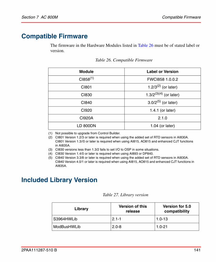
Section 7 AC 800M Compatible Firmware
2PAA111287-510 B 141
Compatible FirmwareThe firmware in the Hardware Modules listed in Table 26 must be of stated label or version.
Included Library Version
Table 26. Compatible Firmware
Module Label or Version
CI858(1)
(1) Not possible to upgrade from Control Builder.
FWCI858 1.0.0.2
CI801 1.2/3(2) (or later)
(2) CI801 Version 1.2/3 or later is required when using the added set of RTD sensors in AI830A. CI801 Version 1.3//0 or later is required when using AI815, AO815 and enhanced CJT functions in AI835A.
CI830 1.3/2(3)(4) (or later)
(3) CI830 versions less than 1.3/2 fails to set I/O to OSP in some situations.(4) CI830 Version 1.4/0 or later is required when using AI893 or DP840.
CI840 3.0/2(5) (or later)
(5) CI840 Version 3.3/8 or later is required when using the added set of RTD sensors in AI830A. CI840 Version 4.0/1 or later is required when using AI815, AO815 and enhanced CJT functions in AI835A.
CI920 1.4.1 (or later)
CI920A 2.1.0
LD 800DN 1.04 (or later)
Table 27. Library version
LibraryVersion of this
releaseVersion for 5.0 compatibility
S3964HWLib 2.1-1 1.0-13
ModBusHWLib 2.0-8 1.0-21

Included Library Version Section 7 AC 800M
142 2PAA111287-510 B
CI865SattIOHwLib 2.0-3 1.0-19
CI854PROFIBUSHwLib 2.0-19 1.0-46
CI860FFHSEHwLib 2.0-28 1.0-62
CI858DriveBusHwLib 2.1-8 1.0-9
CI872MTMHWLib 2.1-1 1.1-1
PrinterHwLib 2.0-4 1.1-0
SerialHwLib 2.0-9 1.1-1
S900IoCI854HwLib 2.0-0 1.1-2
CI868IEC61850HwLib 2.4-0 1.1-23
COMLIHWLib 2.1-2 1.1-31
CI867ModbusTcpHwLib 2.0-39 1.1-82
CI855MB300HwLib 2.0-5 1.2-0
CI856S100HwLib 2.1-2 1.3-1
CI857InsumHwLib 2.1-2 1.22-5
ABBDrvNpbaCI854HwLib 1.0-2 N/A
ABBDrvFenaCI871HwLib 1.0-2 N/A
ABBDrvRetaCI871HwLib 1.0-5 N/A
ABBDrvRpbaCI854HwLib 1.0-2 N/A
ABBMNSiSCI871HwLib 1.0-6 N/A
ABBPnl800CI854HwLib 1.1-0 N/A
ABBProcPnlCI854HwLib 1.0-1 N/A
BasicHwLib 5.1-0 5.0-2
Table 27. Library version
LibraryVersion of this
releaseVersion for 5.0 compatibility

Section 7 AC 800M Included Library Version
2PAA111287-510 B 143
CI853SerialComHwLib 1.0-0 N/A
CI869AF100HwLib 2.0-11 N/A
CI871PROFINETHwLib 1.2-29 N/A
CI873EthernetIPHWLib 1.4-1 N/A
ModemHwLib 1.0-0 N/A
S200IoCI854HwLib 1.0-1 N/A
S800CI801CI854HwLib 1.1-5 N/A
S800CI830CI854HwLib 1.0-10 N/A
S800CI840CI854HwLib 1.1-5 N/A
S800IoModulebusHwLib 1.1-10 N/A
COMLICommLib 1.3-3 N/A
FFHSECommLib 1.3-8 N/A
INSUMCommLib 1.2-4 N/A
MB300CommLib 1.2-3 N/A
MMSCommLib 1.3-4 N/A
ModBusCommLib 1.3-4 N/A
ModBusTCPCommLib 1.2-6 N/A
ModemCommLib 1.2-2 N/A
MTMCommLib 1.1-5 N/A
S3964CommLib 1.3-5 N/A
SattBusCommLib 1.3-2 N/A
SerialCommLib 2.1-3 N/A
Table 27. Library version
LibraryVersion of this
releaseVersion for 5.0 compatibility

Included Library Version Section 7 AC 800M
144 2PAA111287-510 B
AlarmEventLib 1.5-9 N/A
BasicGraphicLib 1.2-2 N/A
BasicLib 1.6-10 N/A
Batchlib 1.2-3 N/A
ControlAdvancedLib 1.4-6 N/A
ControlBasicLib 1.2-5 N/A
ControlExtendedLib 1.3-4 N/A
ControlSolutionLib 1.2-3 N/A
ControlFuzzyLib 1.3-5 N/A
ControlObjectLib 1.2-5 N/A
ControlSimpleLib 1.2-3 N/A
ControlStandardLib 1.4-9 N/A
ControlSupportLib 1.3-7 N/A
FireGasLib 2.4-4 N/A
GraphicSupportLib 1.1-11 N/A
GroupStartLib 1.4-6 N/A
IconLib 1.3-3 N/A
ProcessObjBasicLib 2.4-8 N/A
ProcessObjDriveLib 1.4-6 N/A
ProcessObjExtLib 2.4-11 N/A
ProcessObjInsumLib 1.4-6 N/A
SeqStartLib 1.2-6 N/A
Table 27. Library version
LibraryVersion of this
releaseVersion for 5.0 compatibility

Section 7 AC 800M Included Library Version
2PAA111287-510 B 145
SignalBasicLib 1.1-4 N/A
SignalLib 1.6-11 N/A
SignalSupportLib 1.1-6 N/A
SupervisionBasicLib 1.1-7 N/A
SupervisionLib 2.5-6 N/A
SupportLib 1.3-2 N/A
VMTLib 1.1-0 N/A
Table 27. Library version
LibraryVersion of this
releaseVersion for 5.0 compatibility

Known Problems Section 7 AC 800M
146 2PAA111287-510 B
Known ProblemsThis section details the Known Problems for AC 800M that exist in the system at the time of release.
Installation
Table 28 lists issues that may exist and affect the installation and migration of the system or product at time of release. Workarounds, clarifications, or helpful hints have been provided for each issue wherever possible.
All issues and problems categorized as Controller are valid for both the AC 800M and AC 800M High Integrity controllers.
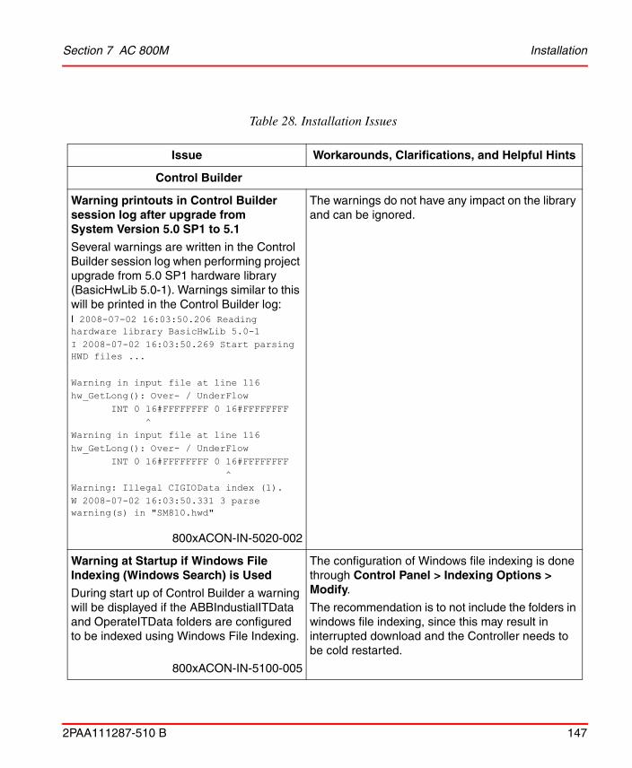
Section 7 AC 800M Installation
2PAA111287-510 B 147
Table 28. Installation Issues
Issue Workarounds, Clarifications, and Helpful Hints
Control Builder
Warning printouts in Control Builder session log after upgrade from System Version 5.0 SP1 to 5.1
Several warnings are written in the Control Builder session log when performing project upgrade from 5.0 SP1 hardware library (BasicHwLib 5.0-1). Warnings similar to this will be printed in the Control Builder log:I 2008-07-02 16:03:50.206 Reading hardware library BasicHwLib 5.0-1I 2008-07-02 16:03:50.269 Start parsing HWD files ...
Warning in input file at line 116hw_GetLong(): Over- / UnderFlow INT 0 16#FFFFFFFF 0 16#FFFFFFFF ^Warning in input file at line 116hw_GetLong(): Over- / UnderFlow INT 0 16#FFFFFFFF 0 16#FFFFFFFF ^Warning: Illegal CIGIOData index (1).W 2008-07-02 16:03:50.331 3 parse warning(s) in "SM810.hwd"
800xACON-IN-5020-002
The warnings do not have any impact on the library and can be ignored.
Warning at Startup if Windows File Indexing (Windows Search) is Used
During start up of Control Builder a warning will be displayed if the ABBIndustialITData and OperateITData folders are configured to be indexed using Windows File Indexing.
800xACON-IN-5100-005
The configuration of Windows file indexing is done through Control Panel > Indexing Options > Modify.
The recommendation is to not include the folders in windows file indexing, since this may result in interrupted download and the Controller needs to be cold restarted.

Administration Section 7 AC 800M
148 2PAA111287-510 B
Administration
Table 29 lists the issues that may exist and affect system or product administration at time of release including user, node and service structure related issues and problems.Workarounds, clarifications, or helpful hints have been provided for each issue wherever possible.
PROFINET IO
Upgrade PROFINET IO Feature Pack
When doing the upgrade of PROFINET IO Feature Pack 1.2 to 800xA 5.1, some settings on CI871 get reset to default values. This affects Default Gateway, Red.Eth.recovery time and Watchdog factor.
800xACON-IN-5100-001
Check CI871 settings after upgrade and enter the previous values if settings are changed.
High memory consumption in Controller when using hardware addresses with high numbers.
When a PROFINET IO device with support of physical device management (PDev) is configured, the memory consumption in the controller increases by 200kb for each device. PDev is supported when high hardware addresses – 32768 to 32770 – are used for the Ethernet adapters below the Device Access Point (DAP) of the device.
800xACON-CN-5100-053
Workaround:
Observe the memory consumption of the controller when adding PROFINET devices below CI871. If the memory has reached a critical level, please contact ABB Technical Support.
Table 28. Installation Issues (Continued)
Issue Workarounds, Clarifications, and Helpful Hints

Section 7 AC 800M Administration
2PAA111287-510 B 149
Table 29. Administration Issues
Issue Workarounds, Clarifications, and Helpful Hints
Control Builder
Controller remains reserved by Control Builder, prevents SM811 Hot Insert
On rare occasions, a controller can remain "reserved" by the Control Builder, which will prevent, for example, an SM811 Hot Insert, or that another Control Builder can reserve the controller. The problem has been seen after Online Upgrade and Power Fail.
The message "Error when calling RelinquishControlReq" is found in the Control Builder session log, and "Already reserved Denied" and "Failed to reserve controller for hot insert" in the controller log.
Important800xACON-AD-5020-009
Terminate Control Builder and MMSService.exe (can be done through the Windows Task Manager). Then restart Control Builder (will also start MMSService.exe).
Disconnecting the network cables for the controller and then reconnecting them may also help.
Controller
INSUM GroupStart Stop During Switch in Online Upgrade
Group Start objects controlling INSUM objects from ProcessObjInsumLib may stop at an online upgrade. The groupstart objects may stop with the following alarm: Too few available objects.
800xACON-AD-5000-031
Re-synchronize the INSUM GroupStart objects manually after the Online Upgrade.

Administration Section 7 AC 800M
150 2PAA111287-510 B
Communication
Communication Variables Unresolved after Simultaneous Download
Automatic resolve between controllers in different projects might fail if the remote controller has not been downloaded before. When simultaneously performing downloads, from different engineering stations to controllers that communicate via Inter Application Communication (IAC), the re-configured communication variables could stay unresolved.
Important800xACON-CN-5100-020
Perform a new download to the Controller that is acting as client.
Delayed Restart of SattBus on TCP/IP at Cold Restart Download
When using SattBus over TCP/IP and downloading the applications with the cold restart option, it may take several minutes before the SattBus communication is up and running.
There is no problem when making a normal (warm restart) download.
800xACON-AD-4100-003
No workaround exists for this issue.
Table 29. Administration Issues (Continued)
Issue Workarounds, Clarifications, and Helpful Hints

Section 7 AC 800M Administration
2PAA111287-510 B 151
I/O status for CI873,CI872, and CI869 indicates Ok before receiving Waiting for Init at hot insert
The I/O channel status for I/O under the CEX modules CI869(AF100), CI872(MOD5) and CI873(EthernetIP/Devicenet) shows Ok (I/O Unit with no errors) for a short moment (approximately, 1s) during hot insert process, before it receives the status Waiting for init.
800xACON-AD-5100-031
No workaround exists for this issue.
I/O Handling
S100: Scanning of DSDI 110 may not Start after Adding a CI856 to a Running Controller
When adding a CI856 unit to an empty base plate (no unit has been configured previously) on a running controller, the scanning of the input channels of DSDI 110 may not start and no indication will be shown. This only happens if the channels of DSDI110 are configured to update on interrupt.
800xACON-AD-5000-002
• Use scanning instead of interrupt based updating.
• Interrupt based updating may be used with caution. If it is used and it does not work the updating can be started by hot remove/hot insert of the CI856 unit.
Table 29. Administration Issues (Continued)
Issue Workarounds, Clarifications, and Helpful Hints

Administration Section 7 AC 800M
152 2PAA111287-510 B
S100: Error for I/O Conflict on Physical Hardware not Cleared
If two S100 I/O boards are strapped to the same address, the CI856 will detect it and set Unit status to “I/O module ID conflict”, on the module which is configured to have that address.
Removing the boards with the conflicting addresses and inserting the board with the correct address does not clear the error.
800xACON-AD-5000-003
Hot remove/insert of CI856 corrects the problem, but stops all I/O communication from CI856 for a while.
Another way, that does not disturb the I/O communication for the working boards, is to change the address of the board to an unused address in the hardware configuration and download it. Then either change the address on the physical board to match the new one or change the address in the hardware configuration to the original address and download the configuration again.
PROFINET IO
I/O-channel status for I/O under CI871 shows ok (0xC0) during hot-insert process
After restart of CI871, for example, due to hot swap, the input channels of the PROFINET devices might get wrong indication. The channel status might be set for a few seconds to good instead of bad, even though the I/O unit is in the phase of being initialized and WaitingToInit or ChannelError is indicated on sub-module level.
800xACON-AD-5102-003
Implement a filter in the application to accept the input data only if the unit status indicates no Error and no WaitingToInit.
Table 29. Administration Issues (Continued)
Issue Workarounds, Clarifications, and Helpful Hints
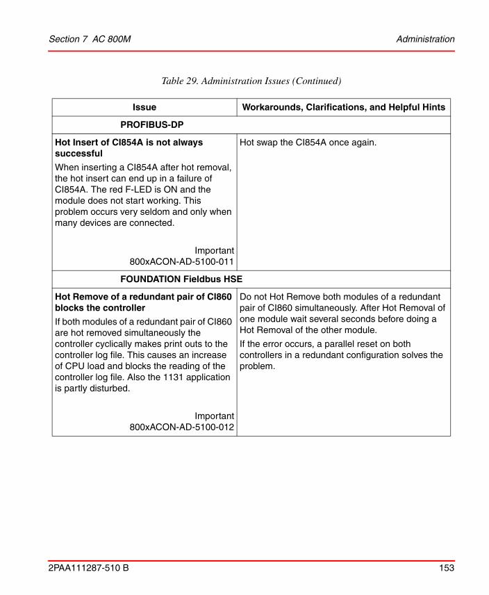
Section 7 AC 800M Administration
2PAA111287-510 B 153
PROFIBUS-DP
Hot Insert of CI854A is not always successful
When inserting a CI854A after hot removal, the hot insert can end up in a failure of CI854A. The red F-LED is ON and the module does not start working. This problem occurs very seldom and only when many devices are connected.
Important800xACON-AD-5100-011
Hot swap the CI854A once again.
FOUNDATION Fieldbus HSE
Hot Remove of a redundant pair of CI860 blocks the controller
If both modules of a redundant pair of CI860 are hot removed simultaneously the controller cyclically makes print outs to the controller log file. This causes an increase of CPU load and blocks the reading of the controller log file. Also the 1131 application is partly disturbed.
Important800xACON-AD-5100-012
Do not Hot Remove both modules of a redundant pair of CI860 simultaneously. After Hot Removal of one module wait several seconds before doing a Hot Removal of the other module.
If the error occurs, a parallel reset on both controllers in a redundant configuration solves the problem.
Table 29. Administration Issues (Continued)
Issue Workarounds, Clarifications, and Helpful Hints

Administration Section 7 AC 800M
154 2PAA111287-510 B
Slow reaction time for LD800HSE failover
CI860 is slow at detecting redundancy failover of the LD800HSE, leading to a communication break in Client/Server communication for up to 35 seconds.
800xACON-AD-5100-005
No workaround exists for this issue.
High Integrity
Control Builder shutting down when downloading to High Integrity Controller
Projects created with the Non-CERT version 5.0 SP2 or versions before 5.0 SP2 RU2 need to be updated by performing a Project Upgrade from the Control Builder after the installation of a later version, for example, 5.0 SP2 RU2 or 5.0 SP2 RU3.If this is not performed, the Control Builder might shut down when attempting a download to the Controller.
800xACON-AD-5020-012
Product Bulletin: 3BSE047421D0054
If this happens a simple manual workaround for this problem is to delete the CTA application and start a new compilation. This compilation will create a new CTA application and allow the application to be downloaded.
(A Compiler Test Application (CTA) is added to the project automatically when a High Integrity Controller is used. CTA ensures that the compiler works properly. There is one CTA only, irrespective of the number of High Integrity controllers.)
Upgrading Firmware in SM810
When updating the firmware in the SM810 unit, always make a controller reset first (long reset). If you do not do that, the controller might stop during the upgrade.
Important800xACON-AD-4100-005
Always make a controller reset first (long reset).
Table 29. Administration Issues (Continued)
Issue Workarounds, Clarifications, and Helpful Hints

Section 7 AC 800M Administration
2PAA111287-510 B 155
Controller might shutdown when restarting interrupted Online Upgrade.
If the Control Builder for some reason is stopped during step 4 in an Online Upgrade (OLU) or in another step when Primary and Trainee PM is not synchronized, this will result in the OLU being aborted. On attempting a new OLU again, shortly after an aborted OLU, could lead to a Controller Shutdown.
800xACON-AD-5022-001
If the Control Builder is stopped or shut down during OLU when the Trainee and Primary Controllers not are fully synchronized, wait until the Controllers are either synchronized or have reached an end state, such as stopped, before attempting a new Online Upgrade.
Controller Shutdown might occur during SIL3 Online Upgrade if “Always update output signals first” is configured
If the task setting “Always update output signals first in next execution” is used for more than one SIL3 task in a Controller, an attempted Online Upgrade might result in a Controller Shutdown.
800xACON-AD-5022-002
Verify that no SIL3 tasks uses the task configuration setting “Always update output signals first in next execution” before initializing an Online Upgrade.
Controller crash when SM Link cable is removed during hot-Insert of SM811
If SM Link cable is removed from primary SM811 during hot-insert of backup SM811, this could result in a controller shut down.
800xACON-AD-5020-030
No workaround exists for this issue.
Table 29. Administration Issues (Continued)
Issue Workarounds, Clarifications, and Helpful Hints

Administration Section 7 AC 800M
156 2PAA111287-510 B
DeviceNet
No status indication in Control Builder DeviceNet I/O modules
No status indication in Control Builder while removing the I/O module for DeviceNet or swapping I/O module to a new position which is different from Control Builder configuration.
Important800xACON-AD-5101-008
No workaround exists for this issue.
For the current release, the status indication for DeviceNet I/O modules is not supported. However status indication is supported for DeviceNet adaptors. Communication will be down for I/O modules which are removed or are swapped to new positions different from that in Control Builder.
Communication Down with LD800DN after CI873 hot swap
Repeated hot swap of the CI873 module lead to communication down with LD800DN and the DeviceNet devices.
Important800xACON-AD-5101-009
Remove the CI873 module again and insert it back. The communication will restart.
Multiple removal and insertion of ethernet cable for the LD 800DN may lead to DeviceNet communication failure
Multiple removal and insertion of the ethernet cable for the LD 800DN may lead to DeviceNet communication failure. This is indicated by all the LED's of the CI873 going off.
Important800xACON-AD-5101-010
Perform a hotswap of the CI873 module. The CI873 will come up and DeviceNet communication will restart.
Table 29. Administration Issues (Continued)
Issue Workarounds, Clarifications, and Helpful Hints

Section 7 AC 800M Administration
2PAA111287-510 B 157
Re-import of EDS file after the Version change is displayed as aborted import
If the user tries to re-import an EDS file with higher major version using DIW in Control builder, the import is successful. However the indication of the import is seen as aborted import on page 1 of the Device Import Wizard.
Important800xACON-AD-5100-019
Incase the user wants to re- import the same EDS file with a higher major version, the user should create a new hardware library manually and import the EDS file with higher major version in that library. Hence, the hardware types for both the old and the new major versions of the EDS file will co-exist in the Control builder project.
MOD 5
Switchover takes 10 seconds after fibre optic cable removal
Loss of data during cable break on primary CI872 module which connects primary CI872 and MOD 5 controller in redundant configuration will be up to 10 seconds.
800xACON-AD-5101-011
In CI872 redundant configuration the MTMReadCyc function block which has cyclic time as one second will observe loss of data for maximum of 9 to 10 cycles when cable break occurs on primary module connecting CI872 to Dow MOD 5 controller before back up module becomes primary.
MOD5 communication fails after hot swap
There could be a delay for the MOD5 communication to start after a hot swap of the CI872 module.
800xACON-AD-5100-033
No workaround exists for this issue.
Table 29. Administration Issues (Continued)
Issue Workarounds, Clarifications, and Helpful Hints

Configuration Section 7 AC 800M
158 2PAA111287-510 B
Configuration
Table 30 lists the issues that may exist and affect configuration of the system or product at time of release. Workarounds, clarifications, or helpful hints have been provided for each issue wherever possible.
Table 30. Configuration Issues
Issue Workarounds, Clarifications, and Helpful Hints
Control Builder
New Variables in POU of Batch Type are Marked Read-Only
If a variable is added in a POU editor for Batch control the variable is marked read-only when the POU is saved.
This is wrong, only variables with Batch Property 'batch' should be read-only.
800xACON-CN-5000-069
The problem disappears if the editor is closed and opened again.
Undo in Sort A-Z and Z-A Fails
If the sort A-Z or Z-A functionality has been used and then the undo button is used, the result will not be as expected.
800xACON-CN-5020-008
Close the editor without saving.

Section 7 AC 800M Configuration
2PAA111287-510 B 159
Using Recursive Relations between Objects or Between Libraries Not Allowed
It is not allowed to use recursive relations between objects or between libraries. By using recursive relations between objects or between libraries, Controller may enter "Non responding mode".
For example, if there exists two function block types A and B, you can declare a sub object of type A in type B, but if later on trying to declare a sub object of type B in type A the Control Builder might hang when the editor content is saved.
800xACON-CN-4100-002
If the Control Builder is not responding it has to be killed using Task Manager and then restarted.
Instance Specific Init Values on Embedded Instances
When copying an Instance in Functional Structure and there are embedded instances of object types with Instance Specific Init values set, these Instance Specific Init values are not copied. The Instance Specific values are lost.
Important800xACON-CN-4100-005
Make sure to check all Instance Specific Init values in the source and make sure these values are set in the copied Instance before the first download.
Table 30. Configuration Issues (Continued)
Issue Workarounds, Clarifications, and Helpful Hints

Configuration Section 7 AC 800M
160 2PAA111287-510 B
String Length of 140 Characters Not Supported for String Constants
The maximum length of a string constant is 137 characters even if the length of the string is set to 140 characters.
800xACON-CN-5020-006
No workaround exists for this issue.
Auto-Reservation Fails for Types Created Using Copy & Paste in Project Explorer
If a Control Module Type or Function Block Type is copied and pasted in the Project Explorer the new type is not auto-reserved.
800xACON-CN-5000-071
The new type needs to be manually reserved by the user.
Restriction Against Moving Tasks Between SIL3 Applications
It is not permitted to move an existing Task between SIL3 Applications as part of a Warm Reconfiguration.
Example: The controller is executing with SIL3App1 connected to Task1, and SIL3App2 connected to Task2. Then SIL3App1 is connected to Task2, and SIL3App2 to NewTask. At download to the controller, the internal diagnostics will (incorrectly) detect this as an illegal reuse of Task2, and perform a shutdown.
Important800xACON-CN-5020-005
Change the Task Settings instead of changing the Task Connection. If the Task Name is changed, do not pick a name that is used by another Task that is still executing.
Table 30. Configuration Issues (Continued)
Issue Workarounds, Clarifications, and Helpful Hints

Section 7 AC 800M Configuration
2PAA111287-510 B 161
Changing CPU Type from PM851
All I/O-modules on Modulebus will be removed if the CPU type PM851 is changed to any other CPU type, such as, PM860. All parameter settings and I/O-connections related to these I/O-modules will be removed.
800xACON-CN-4100-008
The hardware configuration related to the currently used PM851 CPU type, for example, hardware topology, parameter settings and I/O-connections has to be manually stored before the CPU type is changed. This could be done by manually copying relevant information unit by unit to an excel sheet. After the CPU type has been changed, the stored information has to be manually copied back.
Automatic Library Connection when Moving Objects between Applications/Libraries may Fail
It is possible to move/copy objects (Control Module type, Function Block type, Program, Single Control Module) from one application/library to another application/library in Plant Explorer. If the object (or any sub object) is of a type residing in a library not connected to the destination application/library, that library will be automatically connected to the application/library. But if the moved/copied object contains sub objects that not have the Aspect Object property set, the system can not make an automatic connection of the library, it has to be done manually.
800xACON-CN-4100-009
If the auto connection of library fails, and error messages are generated at compilation time. Then connect the needed library manually.
Table 30. Configuration Issues (Continued)
Issue Workarounds, Clarifications, and Helpful Hints

Configuration Section 7 AC 800M
162 2PAA111287-510 B
Using Templates from SeqStartLib Generates the Warning Message: Multiple Calls to Same Function BlockThe Multiple Calls to the Same Function Block compiler switch (introduced in System Version 5.0 SP2) generates warnings for the code that is copied when using the SFC2DSeqChain, for example, from SeqStartLib.
800xACON-CN-5020-010
The warnings can be ignored, or the Multiple Calls to the Same Function Block compiler switch can be set to None.
Power-fail During Download Might Fail
If power fails during download the controller may end up in a state where further reconfigurations are not possible. This will be indicated on the next attempt.
Important800xACON-CN-4100-010
To reconfigure the controller a Controller reset is necessary.
Firmware Upgrade After Remove of Applications in Controller Fails
If application(s) are removed from a running controller from the "Application Information" dialog and then a firmware upgrade is started from the "Firmware Information" dialog the controller will restart and the "Firmware Information" dialog is closed when the controller is up and running again, but the firmware isn't upgraded.
800xACON-CN-5000-003
Start a new firmware upgrade and verify that the firmware has been updated in the controller by using the "Firmware Information" button in the "Remote system dialog" or check the controller log.
Table 30. Configuration Issues (Continued)
Issue Workarounds, Clarifications, and Helpful Hints

Section 7 AC 800M Configuration
2PAA111287-510 B 163
No User in Online Analysis Dialog
If a download is started very soon after reservations of Applications/Controllers are released from another client, then the information about reservations will be wrong in the Online analysis window which says:
This unit is reserved by”-”
800xACON-CN-5020-007
No workaround exists for this issue.
Project Documentation from Control Builder
When using the menu entries “Documentation…” and “Documentation Online…” in the Control Builder it is important to not generate too many pages.
The time needed to generate the documentation in word increases dramatically when the number of pages increases. Sometimes it will take long time before the “Cancel” command is accepted by the system; if the document that is to be generated is very large.
800xACON-CN-5000-006
Instead of one big documentation of for example a large library, divide it into several smaller pieces like data types, function blocks and control modules.
Table 30. Configuration Issues (Continued)
Issue Workarounds, Clarifications, and Helpful Hints

Configuration Section 7 AC 800M
164 2PAA111287-510 B
Erroneous I/O reconfiguration messages at download
At a download to a controller after a (any) change has been done to the Hardware Configuration or settings, there will be warning messages for all S800 modules connected to the ModuleBus.Example:
"Information 9003 : Con_M10:HW Unit 'DO810' at position '0.11.1' will be configured".
800xACON-CN-5020-020
The warnings can be ignored.
Download prohibited if output I/O is disconnected when Copy unconnected outputs is active
If disconnecting an output I/O channel, analog or digital with the option Copy unconnected I/O set to Inputs/Outputs or Outputs, the following warm download will be prohibited with the compile error 9164 - I/O channel was used by another application at last download.
Important800xACON-CN-5020-024
Disable Copy unconnected outputs in the settings on the controller object and initiate a new download.
Table 30. Configuration Issues (Continued)
Issue Workarounds, Clarifications, and Helpful Hints

Section 7 AC 800M Configuration
2PAA111287-510 B 165
Not possible to navigate from I/O Address column to Hardware editor
POU editors in offline has a column called I/O Address where connected I/O appears once the project has been downloaded to controller. The pop up menu for this column lacks the possibility to navigate to the actual Hardware editor.
800xACON-CN-5100-016
No workaround exists for this issue.
Split and Join blocks not found when doing iterative searches
When using Search and Navigation in Diagrams, connections of variables to Split and Join blocks are not found when doing iterative searches. Iterative searches are the default in online mode but can be turned off by disabling the setting "Iterative searches in Online/Test Mode" found in "Tools->Setup->Station->Search and Navigation Settings". For example, it would be expected to find a reference for a structured variable connected to the out port of a join block, but when using iterative searches this reference is not displayed. If a search is done in offline or without iterative search, the connection will be displayed as a reference as it should.
800xACON-CN-5100-017
No workaround exists for this issue.
Controller
Table 30. Configuration Issues (Continued)
Issue Workarounds, Clarifications, and Helpful Hints

Configuration Section 7 AC 800M
166 2PAA111287-510 B
SattBus on TCP/IP is not enabled in hardware simulated controller
In a hardware simulated controller the SattBus TCP/IP communication is disabled.
800xACON-CN-5000-081
Make a warm restart (power fail with battery) of the Controller and then the SattBus TCP/IP communication will be enabled.
Possible data mix-up with bidirectional Inter Application Communication.
A possible data mix-up can happen when changing a user defined data type used for bidirectional Inter Application Communication between two controllers.
This problem can only occur if there is only one component of simple data type in any of the directions (with/without the Reverse attribute) and any of the following attributes of that simple component is changed:
1. The name
2. The Reverse setting
Note: A corresponding modification of the user application (reading/writing) is also necessary in order not to get a compilation error.
800xACON-CN-5100-041
Workaround: Make sure to configure at least two simple components in every direction (on the lowest level when all sub data structures, if any, has been expanded) when using bidirectional Inter Application Communication between two controllers.
Table 30. Configuration Issues (Continued)
Issue Workarounds, Clarifications, and Helpful Hints
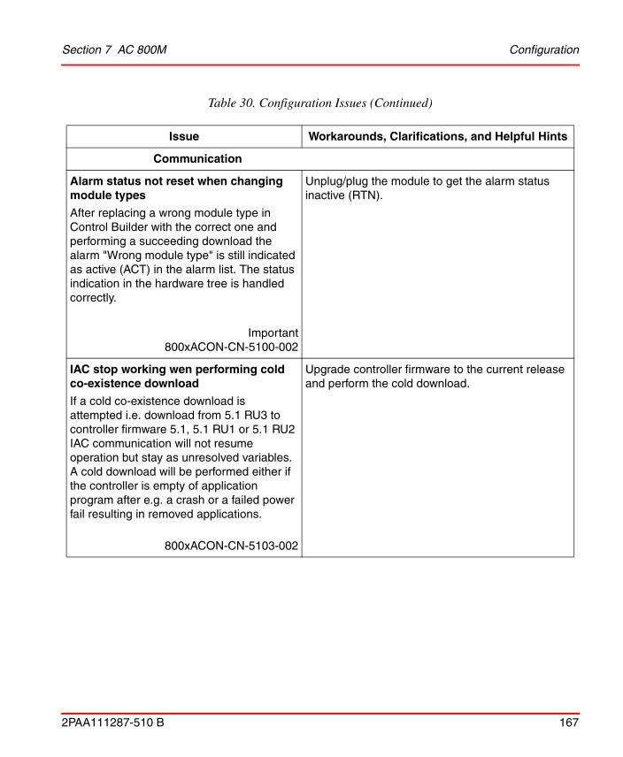
Section 7 AC 800M Configuration
2PAA111287-510 B 167
Communication
Alarm status not reset when changing module types
After replacing a wrong module type in Control Builder with the correct one and performing a succeeding download the alarm "Wrong module type" is still indicated as active (ACT) in the alarm list. The status indication in the hardware tree is handled correctly.
Important800xACON-CN-5100-002
Unplug/plug the module to get the alarm status inactive (RTN).
IAC stop working wen performing cold co-existence download
If a cold co-existence download is attempted i.e. download from 5.1 RU3 to controller firmware 5.1, 5.1 RU1 or 5.1 RU2 IAC communication will not resume operation but stay as unresolved variables. A cold download will be performed either if the controller is empty of application program after e.g. a crash or a failed power fail resulting in removed applications.
800xACON-CN-5103-002
Upgrade controller firmware to the current release and perform the cold download.
Table 30. Configuration Issues (Continued)
Issue Workarounds, Clarifications, and Helpful Hints

Configuration Section 7 AC 800M
168 2PAA111287-510 B
800xA for AC 800M
SeqStartLib Faceplates Deviations
Faceplates in the library SeqStartLib are not fully compliant with the other Control Builder libraries. There are some deviations regarding icon layout, placement of buttons, and so on.
Important800xACON-CN-4100-011
No workaround exists for this issue.
I/O Handling
Controller Crash when Downloading if CI851 not Physically Present
When performing a cold download to a Controller with a CI851 configured and the unit having the “Data Consistency” option activated, this would will lead to a Controller Crash if the CI851 unit is not physically present.
Important800xACON-CN-4100-052
If CI851 with data consistency is used, always verify that the unit is physically present before performing a reconfiguration download.
Table 30. Configuration Issues (Continued)
Issue Workarounds, Clarifications, and Helpful Hints

Section 7 AC 800M Configuration
2PAA111287-510 B 169
Single I/O Modules Configured But Redundant IO Units in Project Explorer
If a redundant I/O module is configured and downloaded, unit A will be the primary and the hardware tree in Control Builder is displayed correctly. If the I/O module is later configured to be single (non-redundant) while unit A (primary, left) is physically removed, the Control Builder Project Explorer hardware tree may end up in a state indicating that the I/O module is redundant and that unit B is primary.
800xACON-CN-5020-004
This is a presentation problem. No workaround exists for this issue.
No Status bit for Disabled Clamp of Analog Out Signals
When the "Clamp Analog out values" parameter on the Controller hardware object is set to false, the corresponding status bit of the RealIO data type will not reflect this.
800xACON-CN-5100-007
No workaround exists for this issue.
Table 30. Configuration Issues (Continued)
Issue Workarounds, Clarifications, and Helpful Hints

Configuration Section 7 AC 800M
170 2PAA111287-510 B
Controller may Shutdown at Reconfiguration of DI880 or DO880 if Field Power is Missing
An AC 800M High Integrity controller may shut down if one or more DO880 and DI880 modules are re-configured when they are in Safe Config State. I/O modules will enter Safe Config State if field power is not present during module startup i.e. during Initial download or Hot Insert of I/O module.
800xACON-CN-5023-007Product bulletin 3BSE047421D0093
To avoid this problem, ensure that the field power is connected to the MTU of the I/O modules that are to be re-configured. If field power cannot be connected to the MTU make sure that the I/O modules leave Safe Config State before reconfiguration. This can be achieved by releasing the I/O modules from their MTU with a screw driver, i.e. the I/O modules will get the status Module Missing instead of Safe Config State.
PROFINET IO
Hirschmann switch RS20 not working as PROFINET IO device
With firmware version 04.2.08 of the Hirschmann switch RS20, the switch provides a new GSD file for PROFINET that is not supported by CI871. The device cannot be configured and is indicated with an Error in the hardware tree.
800xACON-CN-5100-012
Do not configure the switch as PROFINET IO device.
Table 30. Configuration Issues (Continued)
Issue Workarounds, Clarifications, and Helpful Hints

Section 7 AC 800M Configuration
2PAA111287-510 B 171
Maximum number of PROFINET devices reached in LifeList of Web Interface
When having more than 128 PNIO devices connected to one switched Ethernet network, the lifelist in the webserver is not able to show all connected devices. The lifelist reports an error "Lifelist full".
The error typically occurs when several CI871 (connected to one or several AC800M controllers) shares the same Ethernet network, so that all connected devices respond to the DCP requests, independent of being assigned to that CI871 or not.
800xACON-CN-5100-052
Workaround / Corrective actions:
The lifelist is typically used to get the MAC address for devices to be commissioned and assign the device name. But the MAC address is also available on the label on the front or back cover of the PNIO device. With that information the SetDeviceName function in the webserver can be used by configuring the MAC address manually without using the lifelist function.
Table 30. Configuration Issues (Continued)
Issue Workarounds, Clarifications, and Helpful Hints
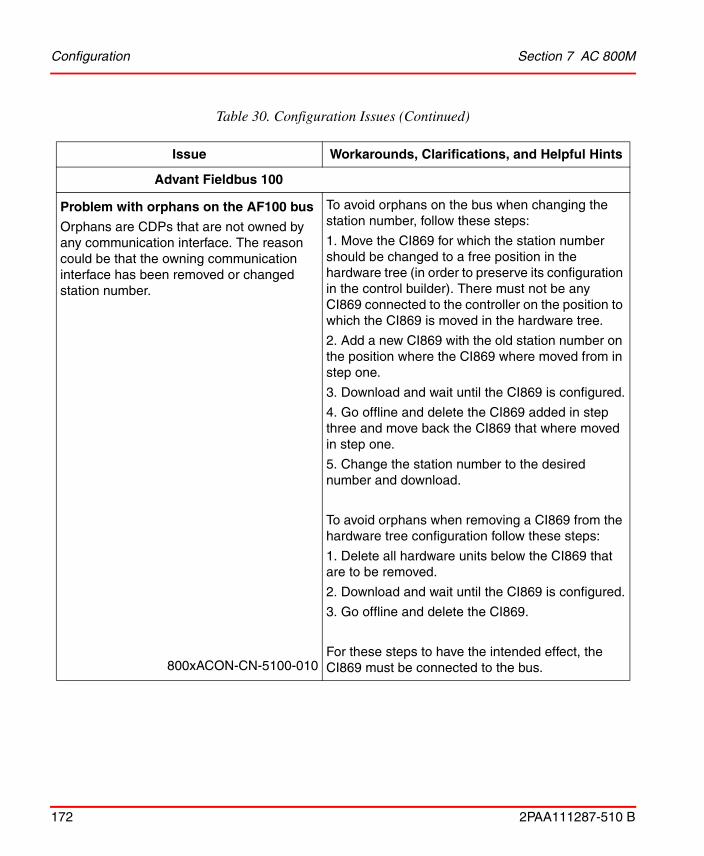
Configuration Section 7 AC 800M
172 2PAA111287-510 B
Advant Fieldbus 100
Problem with orphans on the AF100 bus
Orphans are CDPs that are not owned by any communication interface. The reason could be that the owning communication interface has been removed or changed station number.
800xACON-CN-5100-010
To avoid orphans on the bus when changing the station number, follow these steps:
1. Move the CI869 for which the station number should be changed to a free position in the hardware tree (in order to preserve its configuration in the control builder). There must not be any CI869 connected to the controller on the position to which the CI869 is moved in the hardware tree.
2. Add a new CI869 with the old station number on the position where the CI869 where moved from in step one.
3. Download and wait until the CI869 is configured.
4. Go offline and delete the CI869 added in step three and move back the CI869 that where moved in step one.
5. Change the station number to the desired number and download.
To avoid orphans when removing a CI869 from the hardware tree configuration follow these steps:
1. Delete all hardware units below the CI869 that are to be removed.
2. Download and wait until the CI869 is configured.
3. Go offline and delete the CI869.
For these steps to have the intended effect, the CI869 must be connected to the bus.
Table 30. Configuration Issues (Continued)
Issue Workarounds, Clarifications, and Helpful Hints

Section 7 AC 800M Configuration
2PAA111287-510 B 173
Restart of CI869 when deleting many subunits
If a CI869 configuration has 1500 or more DSPs configured, a re-configuration download where more than 50 DSPs have been deleted or moved can make the CI869 restart. If a redundant CI869 configuration is used, both or only one of the CI869 in the redundant pair might re-start.
Hence, such a reconfiguration might not be bumpless and the unit status for the hardware units below the CI869 will, in case of restart, show warnings related to restart, such as Device failure, and / or device failure on backup.
Important800xACON-CN-5100-011
Delete less than 50 DSP at a time
DeviceNet
DeviceNet Devices with configurable connection sizes are not supported
CI873 with LD 800DN can not communicate with DeviceNet devices for which the connection size depends on the configuration.
Important800xACON-CN-5100-008
Supported DeviceNet devices will have a fixed connection size specified as UINT value in the producing or consuming connection entries of the EDS.
DeviceNet devices with configurable connection sizes are not supported and will have a parameter reference for the connection size in the producing or consuming entries of the EDS.
Table 30. Configuration Issues (Continued)
Issue Workarounds, Clarifications, and Helpful Hints

Configuration Section 7 AC 800M
174 2PAA111287-510 B
Only Devices with a Maximum of 100 Parameters Supported on DeviceNet
Only devices with less than or equal to 100 parameters are supported on DeviceNet. Any device which has more than 100 parameters cannot be configured.
800xACON-CN-5100-019
No workaround exists for this issue.
Reconfiguration of DeviceNet devices through Control Builder will interrupt communication
For reconfiguration of certain communication parameters of DeviceNet devices, there will be stop in input and output communication. These parameters are:
• Electronic keying
• MAC ID change
• Trigger type
• Heart beat
• Ack time
• Inhibit time
800xACON-CN-5101-011
For any reconfiguration related to DeviceNet devices through Control Builder, during download the user will get a prompt saying that DeviceNet communication will be stopped.
For changes to all other configurable parameters of DeviceNet devices, only the output communication will be stopped. Input communication with not be affected.
Table 30. Configuration Issues (Continued)
Issue Workarounds, Clarifications, and Helpful Hints

Section 7 AC 800M Configuration
2PAA111287-510 B 175
Reconfiguration of DeviceNet parameters for LD 800DN causing network to stop and restart
Hot Configuration In Run (HICR) does not work for DeviceNet if certain parameter changes are made. If any of the configurable parameters Interscan delay, Expected packet ratio, ADR enable flag or Background poll ratio of LD 800DN are changed in Control Builder during reconfiguration, the communication for the DeviceNet network will be stopped and restarted again.
800xACON-CN-5101-012
No workaround exists for this issue.
User should be aware of the consequences of the process if such a reconfiguration is done.
Reconfiguration related to IP address inCI873 will lead to restart of CI873 moduleReconfiguration related to IP address in CI873 will lead to restart of CI873 module.
, 800xACON-CN-5101-013
No workaround exists for this issue.
User should be aware of the consequences of the process if such a reconfiguration is done.
EDS Selection page does not save the user input regarding the files selected
EDS Selection page does not save the user input regarding the files selected.
800xACON-CN-5101-014
No workaround exists for this issue.
The engineer needs to be aware of the changes made.
Table 30. Configuration Issues (Continued)
Issue Workarounds, Clarifications, and Helpful Hints

Configuration Section 7 AC 800M
176 2PAA111287-510 B
Re-import of modular I/O EDS file shows the default channels in Device import wizard
Re-import of modular I/O EDS file shows the default channels in Device Import Wizard.
800xACON-CN-5101-015
User should be aware of the channel configuration done in the previous import before a re-import is done.
Missing link path size in Parameters section while selecting the Modular IO’s
While importing EDS files for some of the devicenet modular devices, there could be a window that pops up when user tries to proceed in the Selection window (before the File and Device Information WIndow)
The popup window is shown with the window title as "Improper parameters!" .The window text is displayed as:
"Missing link path size, in Param section, do you want to continue?" or "Invalid default value in Param section, do you want to continue" , and so on.
800xACON-CN-5102-001
Workaround:
Click “Yes” to continue with the import, when such a popup window is displayed in the import process.
Table 30. Configuration Issues (Continued)
Issue Workarounds, Clarifications, and Helpful Hints
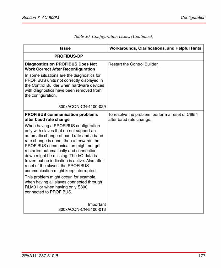
Section 7 AC 800M Configuration
2PAA111287-510 B 177
PROFIBUS-DP
Diagnostics on PROFIBUS Does Not Work Correct After Reconfiguration
In some situations are the diagnostics for PROFIBUS units not correctly displayed in the Control Builder when hardware devices with diagnostics have been removed from the configuration.
800xACON-CN-4100-029
Restart the Control Builder.
PROFIBUS communication problems after baud rate change
When having a PROFIBUS configuration only with slaves that do not support an automatic change of baud rate and a baud rate change is done, then afterwards the PROFIBUS communication might not get restarted automatically and connection down might be missing. The I/O data is frozen but no indication is active. Also after reset of the slaves, the PROFIBUS communication might keep interrupted.
This problem might occur, for example, when having all slaves connected through RLM01 or when having only S800 connected to PROFIBUS.
Important800xACON-CN-5100-013
To resolve the problem, perform a reset of CI854 after baud rate change.
Table 30. Configuration Issues (Continued)
Issue Workarounds, Clarifications, and Helpful Hints

Configuration Section 7 AC 800M
178 2PAA111287-510 B
FOUNDATION Fieldbus HSE
Fraction Cannot be Configured with Fieldbus Builder FF
For analog signals the information min, max, unit and fraction (decimals) can be configured in Fieldbus Builder FF. But only min, max and unit are available after upload in Control Builder. Fraction always gets the default 1.
800xACON-CN-5000-011
A change of the Fraction can be done by setting the value through the application in Control Builder.
FF CS Read block value not updated without error
The Status output parameter of the FF Read/Write Function blocks uses the value 2 to indicate an overrun situation, that is, a new request shall be sent while the response to the previous request has not been received. At the cycle R/W blocks the Warning parameter will additionally be set to true in this situation.
800xACON-CN-5100-014
Typical reasons include insufficient cycle times (internally through cycletime parameter at the cyclic R/W blocks or externally through Req parameter of the non-cyclic R/W blocks) or simultaneous execution of multiple R/W blocks accessing the same CS signal. As a consequence of the overrun situation it cannot be guaranteed that the R/W operation of the affected block has been executed successfully. Furthermore, the block output parameters Valid/Error cannot be relied on for evaluation if a specific operation was successful or not. Therefore the indication of Status 2 requires to increase the cycle time and/or reduce simultaneous use of CS signals to a degree where status 2 is not indicated any longer.
Table 30. Configuration Issues (Continued)
Issue Workarounds, Clarifications, and Helpful Hints

Section 7 AC 800M Configuration
2PAA111287-510 B 179
High Integrity
Controller Warm start (Power fail restart) might fail if SIL3 MMS Safe Peer-to-Peer not have Unique UniqueID’s
If several SIL3 MMS Safe Peer-to-Peer Control modules, that is, MMSDefHI, has the same UniqueID but different access variable names, warm start of the Controller will fail.
Important800xACON-CN-5022-004
Ensure that all MMSDefHI Control Modules have unique UniqueIDs. The situation is indicated during operation since the communication is not working and the affected Control Modules have status code -429.
High Integrity Controller will Shutdown if one POU contains more than 255 Code blocks
It is normally only possible to create 100 Code blocks in one POU (Program Organization Unit). Examples of POUs are Function Blocks and Control Modules. However when using SFC language in a POU will this automatically generate a number of code blocks. If one POU totally contains more than 255 code blocks this will result in that the program flow monitoring measure in the High Integrity Controller detect a sequence error. The problem has only been observed once as a result of a very large SFC sequence in a Control Module.
Important
800xACON-CN-5020-044
Do not use more than 100 SFC steps in a POU that should be used in a High Integrity Controller.
Table 30. Configuration Issues (Continued)
Issue Workarounds, Clarifications, and Helpful Hints

Configuration Section 7 AC 800M
180 2PAA111287-510 B
Controller might shut down if the task name is sub-part of SIL3 application name
In rare cases, depending on creation order, a High Integrity Controller might shut down when a task name is a sub-part of the SIL3 application name.
800xACON-CN-5020-072
If SIL3 applications are used, keep separate standards for the names of tasks and applications.
IEC 61850
Import Wizard shows Warning with incorrect count of CI868 subscribed datasets.
Import Wizard shows Warning in CCF View with incorrect count of CI868 subscribed datasets.
800xACON-CN-5100-026
Ignore the warning as there is no impact on CI868 Performance (Load and Memory).
Table 30. Configuration Issues (Continued)
Issue Workarounds, Clarifications, and Helpful Hints
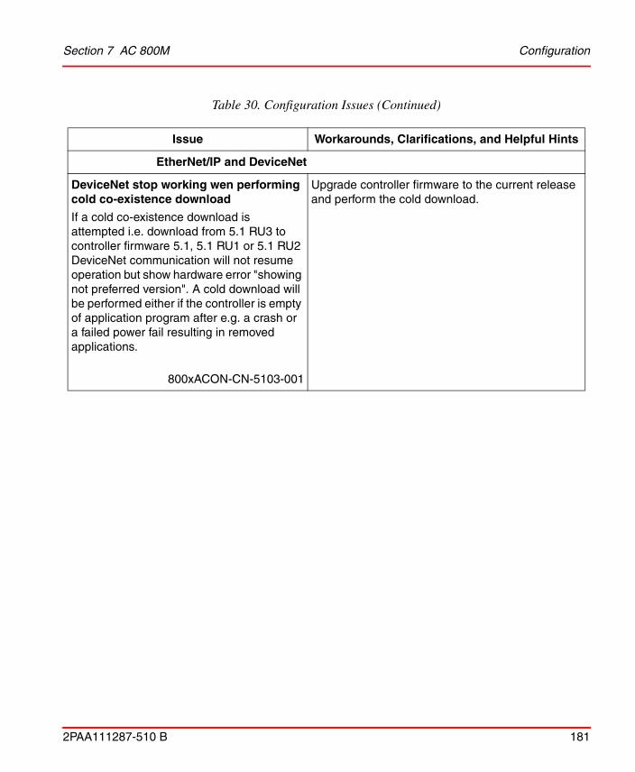
Section 7 AC 800M Configuration
2PAA111287-510 B 181
EtherNet/IP and DeviceNet
DeviceNet stop working wen performing cold co-existence download
If a cold co-existence download is attempted i.e. download from 5.1 RU3 to controller firmware 5.1, 5.1 RU1 or 5.1 RU2 DeviceNet communication will not resume operation but show hardware error "showing not preferred version". A cold download will be performed either if the controller is empty of application program after e.g. a crash or a failed power fail resulting in removed applications.
800xACON-CN-5103-001
Upgrade controller firmware to the current release and perform the cold download.
Table 30. Configuration Issues (Continued)
Issue Workarounds, Clarifications, and Helpful Hints

Operation Section 7 AC 800M
182 2PAA111287-510 B
Operation
Table 31 lists the issues that may exist and affect operation of the system or product at time of release. Workarounds, clarifications, or helpful hints have been provided for each issue wherever possible.
Table 31. Operational Issues
Issue Workarounds, Clarifications, and Helpful Hints
Control Builder
Control Modules – VelocityLimiter and AccelerationLimiter – get reduced inclination when connected to PID controller output
When using VelocityLimiter and AccelerationLimiter to limit the out signal change from PID controller, and if the maximum output is limited, the slope/increase of out signal from the limiting blocks (VelocityLimiter and AccelerationLimiter) will be approximately one third of the configured value.
800xACON-OL-5102-002
This should not pose a problem in most cases, but could visually look strange on trend curves from control loop and limiter blocks.

Section 7 AC 800M Operation
2PAA111287-510 B 183
Load Evaluate Go:Added I/O Connection not Possible to Force in Control Builder Before Go
If a new I/O connection is added and LEG is downloaded, it is not possible to force this I/O channel from the hardware editor in the Control Builder before Go is performed. (There is no problem with forcing I/O connections that already exist).
Forcing the new I/O connection from Evaluate environment in Process works as it should.
800xACON-OL-5000-042
Force the I/O channel from Process Portal.
Load Evaluate Go evaluation not reporting all alarms, if alarm burst occurs If an alarm burst occur during Load Evaluate Go, the evaluation report might fail to present some of the alarms. Single alarm activations during Load Evaluate Go are presented correctly.
800xACON-OL-5020-056
No workaround exists for this issue.
Table 31. Operational Issues (Continued)
Issue Workarounds, Clarifications, and Helpful Hints
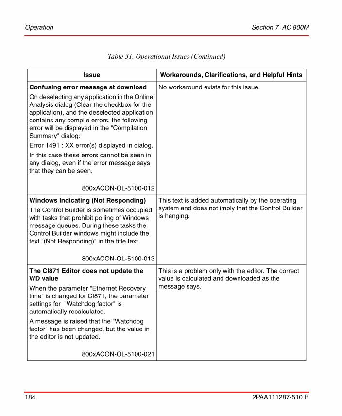
Operation Section 7 AC 800M
184 2PAA111287-510 B
Confusing error message at download
On deselecting any application in the Online Analysis dialog (Clear the checkbox for the application), and the deselected application contains any compile errors, the following error will be displayed in the "Compilation Summary" dialog:
Error 1491 : XX error(s) displayed in dialog.
In this case these errors cannot be seen in any dialog, even if the error message says that they can be seen.
800xACON-OL-5100-012
No workaround exists for this issue.
Windows Indicating (Not Responding)
The Control Builder is sometimes occupied with tasks that prohibit polling of Windows message queues. During these tasks the Control Builder windows might include the text "(Not Responding)" in the title text.
800xACON-OL-5100-013
This text is added automatically by the operating system and does not imply that the Control Builder is hanging.
The CI871 Editor does not update the WD value
When the parameter "Ethernet Recovery time" is changed for CI871, the parameter settings for "Watchdog factor" is automatically recalculated.
A message is raised that the "Watchdog factor" has been changed, but the value in the editor is not updated.
800xACON-OL-5100-021
This is a problem only with the editor. The correct value is calculated and downloaded as the message says.
Table 31. Operational Issues (Continued)
Issue Workarounds, Clarifications, and Helpful Hints

Section 7 AC 800M Operation
2PAA111287-510 B 185
Multiple Value Labels in FD Viewer for Multiple Connections
An output port in a FD code block can be connected to several input ports. In online mode each connection will have its own value label. This means that, multiple connections will have multiple value labels. This will give a cluttered appearance in the online viewer.
800xACON-OL-5100-005
No workaround exists for this issue.
Wrong value for Average Interval Time
The value for Average Interval Time presented in the Overview for Communication variables is a wrong value during the first 10 intervals.
800xACON-OL-5100-005
No workaround exists for this issue.
Confirm write dialogue does not show millisecond part for date and time variables
If the millisecond part of a date and time variable is changed through confirmed write, then the values is not shown in the confirm operation dialog.
800xACON-OL-5101-009
The correct value is written to the Controller and the value can be verified in the online dialog in the Control Builder.
Table 31. Operational Issues (Continued)
Issue Workarounds, Clarifications, and Helpful Hints

Operation Section 7 AC 800M
186 2PAA111287-510 B
PidCascadeLoop function block windup
A controller windup occurs if the signal connected as PV (Process Value) to the slave controller is outside the range of 0 -100 %. This means that a lower value is below 0.0 and or higher value is above 100.0.
Important800xACON-OL-5000-086
If possible, use the scale of 0-100% for slave PV in PidCascadeLopp instead of engineering unit. An alternative for a suitable scale is to use the control module CascadeLoop from ControlSolutionLib.
OPC Server
Live Data Lost In Process Graphics after Download if Controller Is Unavailable
If there is no connection to all controllers during a download, there could be a loss of live data in the process graphics. The time for which the live data is lost could be from a couple of seconds to minutes depending of how many Controllers have lost their connection.
800xACON-OL-5010-026
Disconnect all controllers that are not on the network from the OPC Data Access part.
Table 31. Operational Issues (Continued)
Issue Workarounds, Clarifications, and Helpful Hints

Section 7 AC 800M Operation
2PAA111287-510 B 187
800xA for AC 800M
Truncated Task Names in Alarm and Event Lists
A task name containing more than 8 characters will be truncated when displayed in alarm and event lists.
Example:
LongTaskName_1
will be shown as
LongTask
800xACON-OL-4100-004
Keep task names at a maximum of 8 characters.
Wrong Status in Alarm List for Redundant Hardware Units
Redundant hardware units report “Redundant mode enabled” instead of “Status OK” in the Alarm List, in Plant Explorer, when the alarm state changes from active to inactive.
800xACON-OL-5000-005
No workaround exists for this issue.
Table 31. Operational Issues (Continued)
Issue Workarounds, Clarifications, and Helpful Hints

Operation Section 7 AC 800M
188 2PAA111287-510 B
Mix of old and new icons in Control Builder and Plant Explorer
New icons have been introduced in System Version 5.1 on objects in Control Builder and Plant Explorer.
In some situations the old icons are still visible on objects in Plant Explorer.
For example, when creating instances of function block/control module types having the default icon from libraries created before System Version 5.1.
800xACON-OL-5100-036
No workaround exists for this issue.
Controller
Wrong Access rights for Confirmed Write.
The access right for one variable might under special circumstances assume the access right of the same variable as configured on a different object level. The problem could only occur if the same variable has different access levels configured on different hierarchical levels in the application.
800xACON-OL-5010-042Product bulletin 3BSE047421D0146
Use same access right configuration for a variable on all hierarchical levels in the application.
Table 31. Operational Issues (Continued)
Issue Workarounds, Clarifications, and Helpful Hints

Section 7 AC 800M Operation
2PAA111287-510 B 189
Latency Caused by Alarm Burst
When an alarm changes state (gets activated, deactivated, or acknowledged), a small increment to the Task Execution time for a single scan (approximately 350 µs per changed alarm) will be added. If an alarm burst occurs, when many alarms are activated simultaneously, this could noticeably increase the Task Execution time. If latency supervision is enabled on the tasks that are executing the Alarm Condition Function Blocks or Control Modules, this could lead to a latency shutdown, if the Task settings are too tight.
NOTE: Latency supervision is always enabled for SIL tasks.
Important800xACON-OL-4100-044
Consider the extra time for an alarm burst when tuning the task settings in the Controller, especially the Interval, Offset, and Latency settings. An alarm burst of 100 alarms (in one scan) adds about 35 ms to the execution time, 200 alarms adds 70ms, and so on.
Controller Can Hang if Tool Port Cable is not Connected in the Other End
A cable connected to the tool port on the CPU (COM4), may cause the controller to hang during startup, if the cable is unconnected in the other end, or if the PC it's connected to is unpowered.
800xACON-OL-4100-009
Do not have an unconnected cable attached to COM4.
Table 31. Operational Issues (Continued)
Issue Workarounds, Clarifications, and Helpful Hints

Operation Section 7 AC 800M
190 2PAA111287-510 B
Error Printout in Controller Log from CI853
When using CI853, logging severity low errors (done by changing Error handler settings under "Controller settings menu") might result in error logs:
E 2004-10-12 11:09:35.336 ErrorHandler PM: CON 4119 Spur CEX IRQ 9 (1,1) spur IRQ since start
Important800xACON-OL-4100-010
The errors are harmless, but to avoid the printout, turn off logging of Severity low errors in the Control Builder in the "Controller Settings menu".
Table 31. Operational Issues (Continued)
Issue Workarounds, Clarifications, and Helpful Hints

Section 7 AC 800M Operation
2PAA111287-510 B 191
Communication
Safe Peer-to-Peer communication timeout
The default timeout for the MMSRead Control Modules for Safe P2P communication is 2 seconds. This is sufficient to handle a single TCP retransmission, but double TCP retransmissions may occur infrequently, depending on network and controller load. The second retransmission will occur after approximately 4 sec.
Important800xACON-OL-5020-008
To ensure that double TCP re-transmissions are handled without setting the safe P2P communication invalid, a P2P timeout of at least 5 seconds is required.
Shutdown of Active PPP Node can Cause other Node to Shut Down
The controller acting as a passive PPP node may shut down if the controller acting as the active PPP node is shut down.
Important800xACON-OL-4100-012
Make sure the active controller does not stop. Use UPS (Uninterruptedly Power Supply) if necessary. Or try to use other communication protocols, if possible.
Table 31. Operational Issues (Continued)
Issue Workarounds, Clarifications, and Helpful Hints
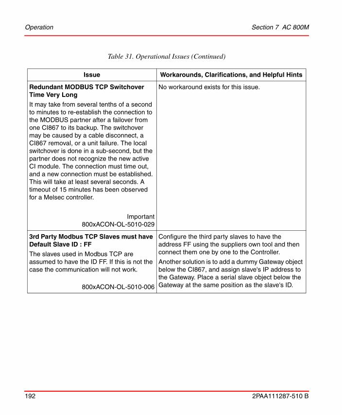
Operation Section 7 AC 800M
192 2PAA111287-510 B
Redundant MODBUS TCP Switchover Time Very Long
It may take from several tenths of a second to minutes to re-establish the connection to the MODBUS partner after a failover from one CI867 to its backup. The switchover may be caused by a cable disconnect, a CI867 removal, or a unit failure. The local switchover is done in a sub-second, but the partner does not recognize the new active CI module. The connection must time out, and a new connection must be established. This will take at least several seconds. A timeout of 15 minutes has been observed for a Melsec controller.
Important800xACON-OL-5010-029
No workaround exists for this issue.
3rd Party Modbus TCP Slaves must have Default Slave ID : FF
The slaves used in Modbus TCP are assumed to have the ID FF. If this is not the case the communication will not work.
800xACON-OL-5010-006
Configure the third party slaves to have the address FF using the suppliers own tool and then connect them one by one to the Controller.
Another solution is to add a dummy Gateway object below the CI867, and assign slave's IP address to the Gateway. Place a serial slave object below the Gateway at the same position as the slave's ID.
Table 31. Operational Issues (Continued)
Issue Workarounds, Clarifications, and Helpful Hints
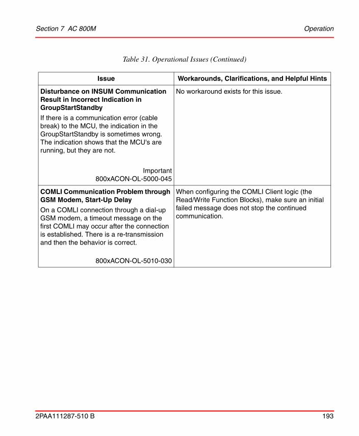
Section 7 AC 800M Operation
2PAA111287-510 B 193
Disturbance on INSUM Communication Result in Incorrect Indication in GroupStartStandby
If there is a communication error (cable break) to the MCU, the indication in the GroupStartStandby is sometimes wrong. The indication shows that the MCU's are running, but they are not.
Important800xACON-OL-5000-045
No workaround exists for this issue.
COMLI Communication Problem through GSM Modem, Start-Up Delay
On a COMLI connection through a dial-up GSM modem, a timeout message on the first COMLI may occur after the connection is established. There is a re-transmission and then the behavior is correct.
800xACON-OL-5010-030
When configuring the COMLI Client logic (the Read/Write Function Blocks), make sure an initial failed message does not stop the continued communication.
Table 31. Operational Issues (Continued)
Issue Workarounds, Clarifications, and Helpful Hints

Operation Section 7 AC 800M
194 2PAA111287-510 B
Negative Values not Correct in CI867 Slave
When a negative value is written to the CI867 slave, using the function block MBTCPWrite() at address %QD100(or R100), the variable in the slave end displays an unexpected value.
Examples:
• -32767 (From the MBTCPWrite block) --> 32769 showed in slave CI867 address.
• -1 (From the MBTCPWrite block)--> 65535 showed in slave CI867 address.
Important800xACON-OL-5100-067
A workaround for this problem is:
1. A variable 'TempRead1'of type dint is connected to the access variable, say, %MD100
2. Declare a variable, say, 'TempWord' of type 'word'
3. Convert the read value using the 1131 function dint_to_word(TempRead1) and assign it to TempWord
4. Again, convert the TempWord to int using 1131 function word_to_int(TempWord) and assign it back to TempRead1
After this conversion process, we will be able to read/receive the actual transferred negative data.
IEC61850
Channel error occurs when variable is connected to 'ModIn' channel
A Channel error occurs when variable is connected to 'ModIn' channel under the path CI868 --> MyIED --> LD --> LN0.
Protocol information is not updated for ModIn channel of LN0 object.
800xACON-OL-5100-085
No workaround exists for this issue.
Table 31. Operational Issues (Continued)
Issue Workarounds, Clarifications, and Helpful Hints

Section 7 AC 800M Operation
2PAA111287-510 B 195
I/O Handling
I/O Running on CI865 Started too Late
Warning!
Start of Applications and I/O running on CI865 are not synchronized at startup. The controller applications may start before all CI865 I/O has been started.
Important800xACON-OL-5000-010
Use the IO.Status value to interlock start-up actions.
OSP Values are Reset During Startup
Warning!The following issue occurs after the application(s) in the controller for some reason are erased (for example after a power fail with no attached battery or after making a long press on INIT). The I/O channels will in this state have entered their pre-configured OSP values. In order to restart the controller, the application(s) must be re-downloaded from Control Builder.
When the download of the application(s) is performed, just before the applications are restarted, I/O channels with pre-configured OSP values will be de-energized for a couple of seconds. After that, the I/O will be set by the now running application(s).
Important800xACON-OL-4100-014
Prior to the download; make sure the process is set into a state were it can accept the temporarily de-energized outputs.
Table 31. Operational Issues (Continued)
Issue Workarounds, Clarifications, and Helpful Hints

Operation Section 7 AC 800M
196 2PAA111287-510 B
S900: I/O OSP Cleared
Warning! OSP on S900 I/O will be cleared in the following two occasions:
• During a short period of time after resuming after a controller power fail.
• Controller task abort, due to a task having executed for too long.
Important800xAIO9-OL-4100-001
No workaround exists for this issue.
Unable to Acknowledge Warning for CI920
If a redundant pair of CI920 are configured, the hardware status displayed in the Control Builder is "redundant switch over"; this warning is not possible to acknowledge.
800xACON-OL-4100-018
The functionality of the S900 I/O does not affect this case.
Table 31. Operational Issues (Continued)
Issue Workarounds, Clarifications, and Helpful Hints

Section 7 AC 800M Operation
2PAA111287-510 B 197
No Channel Error from S900 I/O if Wire Break or Short Circuit
Digital inputs, digital outputs and analog outputs on S900 I/O does not report data quality 'bad' in the RealIO.Status component in case of wire break or short circuit. This is because S900 I/O sends this information through PROFIBUS diagnostics.A line fault on such channels results in:
• No system alarm with plain text
• A PID controller may go into windup
• The OPC status will not show bad
• History and trend will show good
• Process graphics will show good
Important800xACON-OL-5000-004
No workaround exists for this issue.
Problem to Use Long I/O Scan Cycle Time in Redundant AC 800M Using DP820
Scan cycle time of more than 90ms results in the DP820 going to OSP state for some seconds.
800xACON-OL-5000-008
Set Modulebus scan cycle time to a maximum of 90ms.
Table 31. Operational Issues (Continued)
Issue Workarounds, Clarifications, and Helpful Hints

Operation Section 7 AC 800M
198 2PAA111287-510 B
Problems with rmcPTCLib in AC 800M
Hot Swap of CI856 in an AC 800M is not supported if rmcPTCLib is used. In that case a Hot Remove of the CI856 may cause a Controller Crash.
PowerFail restart with CI856 in AC 800M may cause a Controller Crash if rmcPTCLib is used.
800xACON-OL-4104-001
Load the project on a CF card so that the application restarts if there is a controller crash.
PROFIBUS-DP
CI854 Stays in Fail Mode after Shortcut of PROFIBUS Line
Under some very special circumstances, a shortcut of both PROFIBUS lines can cause the CI854 to stay in STOP mode, as the cyclic communication is disturbed.
800xACON-OL-5010-025
Reset the CI854 after the shortcut is resolved.
FOUNDATION Fieldbus HSE
Pending Error Messages in Hardware Unit Status Are Reset
A CI860 module with the HSE network disconnected indicates 'Channel Error' in the Hardware Unit Status. If the CI860 is reset under this condition, it will restart without showing the error even though the HSE cable may still be disconnected. The same will also happen after a controller cold start.
800xACON-OL-4100-020
Check the status information on the single FF signals to find out about the actual communication status after restart.
Table 31. Operational Issues (Continued)
Issue Workarounds, Clarifications, and Helpful Hints

Section 7 AC 800M Operation
2PAA111287-510 B 199
Problems with FF Status Value Initialization
The FF status values are not always properly initialized or reset. There are two different actions when these FF status values need to be initialized:
• starting a CI860 module
• removing a channel/signal on one side of a Controller>FF / FF>Controller signal connection
The CI860 I/O-channels are initialized with zeros when a CI860 module starts. This leads to a FF status of 0 on connections, which are used, but not updated. The problem exists in both directions IEC>FF and FF>IEC.
Removing a channel/signal:If the writing side of a Controller>FF signal connection is removed, the last written value, especially the status, is kept. On an FF>Controller signal connection the status is set to 'BAD', if the FF signal is removed, which is ok.
Starting a CI860 module:The current implementation does not ensure, that no longer used values are indicated by a 'BAD' FF status.
800xACON-OL-4100-021
Pay attention to remove variables connected to channels on CI860 that are no longer connected to an FF application, since they are incorrectly indicated as OK.
Table 31. Operational Issues (Continued)
Issue Workarounds, Clarifications, and Helpful Hints

Operation Section 7 AC 800M
200 2PAA111287-510 B
FFHSE C/S Read and Write request gets status error (2) first and then status OK
FFHSERead and FFHSEWrite function blocks might temporarily indicate error status 2 which means warning. But the requests are operated successfully and status gets OK finally.
800xACON-OL-5101-010
Wait for some time after sending the request, before operating the error status.
CI860: Client/server connection breaks after change of IP address
When changing the IP-addresses of a redundant pair of CI860 the active Client/Server communication via FFHSERead and FFHSEWrite is stopped. The cyclic Publish / Subscribe communication is not affected. Changing the IP-address of a non-redundant CI860 is working with C/S as supposed.
Important800xACON-OL-5101-011
Perform HotSwap of primary CI860 to restart the Client/Server communication.
Table 31. Operational Issues (Continued)
Issue Workarounds, Clarifications, and Helpful Hints

Section 7 AC 800M Operation
2PAA111287-510 B 201
High Integrity
SIL3 discrepancy shutdown when replacing AI880
If a faulty single S800 Safety I/O module is used in a redundant backplane and the module is used in a SIL3 application the controller may shutdown if a healthy module is inserted in the free position of the backplane before the faulty unit is removed.
Important800xACON-OL-5100-062
No workaround exists for this issue.
MOD 5
Internal FW error in CI872 at application download
Internal FW error in CI872 at application download and CI872 modules are not up. The message "Internal HW Error (see CI Log)" alarm is shown, and both CI872 modules in case of redundancy or single CI872 module in case of non-redundancy are not up.
Important800xACON-OL-5100-066
Workaround for this scenario, where no CI872 module is up, is to manually hot swap the CI872 modules.
Table 31. Operational Issues (Continued)
Issue Workarounds, Clarifications, and Helpful Hints

Operation Section 7 AC 800M
202 2PAA111287-510 B
Switchover occurs despite CPUID conflict in backup CI872
Failover from primary CI872 module to the backup CI872 module occurs, even though CPUID conflict exists in the backup CI872 module.
800xACON-OL-5023-006
In a redundant configuration of CI872 modules, always ensure that the backup CI872 is correctly configured, by checking its unit status in the Hardware Tree.
MTMConnect FB doesn't show '-7006' while FOC is disconnected
The MTMConnect function block does not update the status of the physical connection when MTMReadCyc or MTMDefCyc function blocks are not connected to that MTMConnect.
800xACON-OL-5023-008
This occurs when MTMConnect is not connected to MTMReadCyc or MTMDefCyc function blocks of MTMCommLib. If any error in the physical connection occurs, the status code -7006 (for any error in physical connection) is not displayed for MTMConnect.
To get an update of the status of the physical connection through an MTMConnect function block in an application, either connect an MTMReadCyc function block to the MTMConnect and enable this MTMReadCyc, or connect an MTMDefCyc function block to the MTMConnect.
DeviceNet
Table 31. Operational Issues (Continued)
Issue Workarounds, Clarifications, and Helpful Hints

Section 7 AC 800M Miscellaneous
2PAA111287-510 B 203
Miscellaneous
Table 32 lists the problems or issues known to exist with the current release that do not fit into one of the other categories. Workarounds, clarifications, or helpful hints have been provided for each issue wherever possible.
No support for Underflow/Overflow indication for Analog modules on DeviceNet
There is no indication shown to user in case of Underflow/Overflow for Analog modules on DeviceNet.
Important
800xACON-OL-5100-069
No workaround exists for this issue.
Table 32. Miscellaneous Issues
Issue Workarounds, Clarifications, and Helpful Hints
Using "diskpart" tool to partition CF cards requires administrator rights
The manual 3BSE035980-510 System 800xA Control AC 800M Configuration, does not specify this condition required for performing automatic partition of CF cards from Control Builder.
800xACON-MC-5100-001
The user performing automatic partition CF cards from Control Builder must have Administrator rights on the PC and Windows 7 UAC must be turned off.
Table 31. Operational Issues (Continued)
Issue Workarounds, Clarifications, and Helpful Hints

Preparations Before an Online Upgrade of an AC 800M using CI857 Section 7 AC 800M
204 2PAA111287-510 B
Preparations Before an Online Upgrade of an AC 800M using CI857
Use the INSUM MMI or the INSUM OS to set the parameter “FailSafe Heartbeat” on the INSUM TCP/IP Gateway to a value which is 1/4 of the shortest “Failsafe TimeOut” on the connected INSUM devices (MCUs, Circuit Breakers).
In normal operation CI857 sends FailSafe heartbeat messages to the INSUM subnets according to the parameters on the INSUMGateway hardware unit.
During the online upgrade, CI857 disconnects from the INSUM system for some time and since there is no redundancy for CI857 no commands can be sent to the INSUM system and the measurement values are not updated during this time.
After the online upgrade CI857 reconnects to the INSUM system and the communication is reestablished.
The time the connection is broken between CI857 and the INSUM system is different depending on if the firmware of CI857 is upgraded or not.
If the firmware of CI857 is upgraded, it is done in step 8 of the online upgrade together with “the remaining units”.
Before CI857 disconnects from the INSUM system it requests the INSUM TCP/IP Gateway to send Failsafe Heartbeat to all INSUM subnets so that this continues until the CI857 reconnects.
If CI857 for some reason does not reconnect within the expected time the INSUM TCP/IP Gateway stops sending Failsafe Heartbeat to the INSUM devices (MCUs and Circuit Breakers) and they will go to Failsafe. The timeout used by the INSUM TCP/IP gateway is set by the AC 800M depending on the expected time until it can reconnect. This is described below.
If the firmware of CI857 is not upgraded the communication between CI857 and the INSUM system is broken for some seconds during step 7 of the online upgrade. This is the case if the firmware is up-to-date already before the online upgrade of the controller and an upgrade of CI857 is indicated as “Not Available” in step 2 of the online upgrade. This is also the case if an upgrade of CI857 is indicated as “Recommended” in step 2 of the online upgrade, but the user decides not to upgrade. If the CI857 does not reconnect within 15 seconds after the switch in step 7 the INSUM devices will go to failsafe.

Section 7 AC 800M Preparations Before an Online Upgrade of an AC 800M using CI857
2PAA111287-510 B 205
If an upgrade of CI857 is indicated as “Recommended” and the user decides to do the upgrade the communication between CI857 and the INSUM system is broken two times. First for some seconds during step 7 and then later for a longer time during step 8 while the firmware is downloaded. Between these communication breaks the communication is executed as normal. If the CI857 does not reconnect within 300 seconds after the start of the firmware download the INSUM devices will go to failsafe.
If an upgrade of CI857 is indicated as “Mandatory” the communication CI857 and the INSUM system is broken at the switch in step 7 and not reestablished until after the upgrade of the firmware of CI857. If the CI857 does not reconnect within 900 seconds after the switch the INSUM devices will go to failsafe.
In this upgrade case it is important to notice that the time the communication is broken depends on how long time the user waits in step 8 in the online upgrade wizard.
During the switch in step 7 the Status of the INSUMReceive and INSUMWrite blocks may be -5324 or -15 for up to 8 seconds. The user needs to take this into account in the application. ProcessObjInsumLib takes care of this internally.
If an upgrade has been started and the communication between the CI857 and the INSUM TCP/IP Gateway is interrupted during step 3, where Redundancy is turned off, the upgrade will be terminated.
The upgrade is possible to perform if the communication between the CI857 and the INSUM TCP/IP Gateway is disconnected during the entire upgrade session.

Preparations Before an Online Upgrade of an AC 800M using CI857 Section 7 AC 800M
206 2PAA111287-510 B

2PAA111287-510 B 207
Section 8 PLC Connect and SoftPoint Server
Known ProblemsThis section details the Known Problems for the PLC Connect and SoftPoint Server that exist in the system at the time of release.
Installation
Table 33 lists issues that may exist and affect the installation and upgrade of the system or product at time of release. Workarounds, clarifications, or helpful hints have been provided for each issue wherever possible.
Table 33. Installation Issues
Issue Workarounds, Clarifications, and Helpful Hints
PLC Connect Install Location.800xAPLC-IN-5000-001
PLC Connect will not function correctly if installed in any other location other than the default location. This affects both PLC Connect and the SoftPoint server.
Can Only Deploy SoftPoints on SoftPoint Server.
Important800xASYI-IN-5010-018
If System Installer is used when the SoftPoint Server is installed without PLC Connect, then the firewall is not configured for SoftPoint Server.
Do a manual configuration (described in System 800xA 5.0 SP1 Automation System Network Design and Configuration) or use the SoftPoint Server node to manage the SoftPoint Server.
It is likely to affect SoftPoint server.

Configuration Section 8 PLC Connect and SoftPoint Server
208 2PAA111287-510 B
Configuration
Table 34 lists the issues that may exist and affect configuration of the system or product at time of release. Workarounds, clarifications, or helpful hints have been provided for each issue wherever possible.
Table 34. Configuration Issues
Issue Workarounds, Clarifications, and Helpful Hints
Unable to add a controller using the SattBus protocol from the shortcut menu.
800xAPLC-CN-5102-001
Add a controller from the generic control network configuration aspect.
Upgrade from 4.1 or older to 5.0 does not work correctly.
Important800xAPLC-CN-5010-007
The old Alarm Control Aspect cannot be deployed in System Version 5.0. Therefore this must be changed to the new Alarm Control Aspect made for System Version 5.0.
After executing the above specified changes, PLC Connect Service group for the Event collector must be changed.
In the aspect Service Group Definition, change Collecting Mapping to "Ads OPC Event Server". Also the Event/Alarm list must be reconfigured. Do not use lists with 4.1 in front of name.
Ensure to use Display Tool after these changes.
It is likely to affect SoftPoint server.
Not possible to change the SB-channel.800xAPLC-CN-5011-004
After deploy the CommServer is owner of the SB-driver and therefore it is not possible to change the SB-channel.
Workaround: Stop the CommServer.
It is not likely to affect SoftPoint server.
Minimum size of Modbus telegrams too large in PLC Connect.
800xAPLC-CN-5020-011
The Modbus driver does not support telegrams smaller than 32 Coils and 16 registers. This does not affect the SoftPoint server.

Section 8 PLC Connect and SoftPoint Server Operation
2PAA111287-510 B 209
Operation
Table 35 lists the issues that may exist and affect operation of the system or product at time of release. Workarounds, clarifications, or helpful hints have been provided for each issue wherever possible.
Table 35. Operational Issues
Issue Workarounds, Clarifications, and Helpful Hints
The Deploy server sometimes cannot read the object configuration.
Important800xAPLC-OL-5100-005
Product Bulletin: 9ARD122017-033
Contact the ABB support line if you require assistance with this issue.
Limiter Alarms are not individually visualized in the Object Dialogue.
Important800xAPLC-OL-5011-001
The Limiter Alarms that is disabled through the PCA property LimiterXisDisabled is not visualized.
It is likely to affect SoftPoint server.
Huge increase in gdi object count while clicking the softpoint objects.
Important800xAPLC-OL-5100-003
If you perform a consistency check on an application containing a large amount of PLC Connect or Softpoint signals the consistency checker tool can crash. If this happens select smaller portions of the PLC Connect/Softpoint application and run the consistency checker in several repetitions.
This affects both PLC Connect and the Softpoint server.

Operation Section 8 PLC Connect and SoftPoint Server
210 2PAA111287-510 B

2PAA111287-510 B 211
Section 9 Multisystem Integration
Known ProblemsThis section details the Known Problems for Multisystem Integration that exist in the system at the time of release.
Configuration
Table 36 lists the issues that may exist and affect configuration of the system or product at time of release. Workarounds, clarifications, or helpful hints have been provided for each issue wherever possible.
Table 36. Configuration Issues
Issue Workarounds, Clarifications and Helpful Hints
Using "Clean" in Multisystem Integration with many objects uploaded will cause severe disturbance in the subscriber system and will result in an unresponsive system.
Important 800xAMI-CN-5010-003
Use "Clean" only during maintenance stop of the subscriber system.

Configuration Section 9 Multisystem Integration
212 2PAA111287-510 B

2PAA111287-510 B 213
Section 10 SFC Viewer
Known ProblemsThis section details the Known Problems for SFC Viewer that exist in the system at the time of release.
Operation
Table 37 lists the issues that may exist and affect operation of the system or product at time of release. Workarounds, clarifications, or helpful hints have been provided for each issue wherever possible.
Table 37. Operational Issues
Issue Workarounds, Clarifications, and Helpful Hints
SFC Viewer shows incorrect data of the transition when the variable used within that transition has hidden attribute.
Important800xASFC-OL-5101-002
In the transition do not select hidden attributes of the variable.
If the Diagram Input Parameters are used in the Transition criterion logic, the resulting Transition Display of the SFC viewer will not show the live data.
800xASFC-OL-5102-001
-

Operation Section 10 SFC Viewer
214 2PAA111287-510 B

2PAA111287-510 B 215
Section 11 Process Engineering ToolIntegration
Known ProblemsThis section details the Known Problems for Process Engineering Tool Integration that exist in the system at the time of release. It also enumerates known problems encountered in the final testing of this product release and identifies workarounds that help overcome the problem.
Operation
Table 38 lists the issues that may exist and affect operational of the system or product at time of release. Workarounds, clarifications, or helpful hints have been provided for each issue wherever possible.
Table 38. Operational Issues
Issue Workarounds, Clarifications, and Helpful Hints
An exception message appears if Process Engineering Tool Integration is asked to perform a transformation without selecting any transformation.
800xAENP-OL-5100-009
Select at least one transformation before performing Transformer in Process Engineering Tool Integration.
Also, when an exception occurs, click Continue to ignore the exception and then click Back to exit the Transformer and proceed.

Operation Section 11 Process Engineering Tool Integration
216 2PAA111287-510 B
System stops with System out of memory error message, whenever loading a huge (more than 60 MB) CAEX file for the second time.
Important
800xAENP-OL-5100-010
Close the application. Reopen it and reload the file.
Unhandled exception error is displayed, if the CAEX Editor is closed using the X (close) button placed in the top right corner of the window.
800xAENP-OL-5100-011
Always use the Cancel button to close the CAEX Editor.
Table 38. Operational Issues (Continued)
Issue Workarounds, Clarifications, and Helpful Hints

2PAA111287-510 B 217
Section 12 IEC 61850
Known ProblemsThis section details the Known Problems for the IEC 61850 that exist in the system at the time of release.
Installation
Table 39 lists issues that may exist and affect the installation and upgrade of the system or product at time of release. Workarounds, clarifications, or helpful hints have been provided for each issue wherever possible.
Configuration
Table 40 lists the issues that may exist and affect configuration of the system or product at time of release. Workarounds, clarifications, or helpful hints have been provided for each issue wherever possible.
Table 39. Installation Issues
Issue Workarounds, Clarifications, and Helpful Hints
Canceling IEC61850 OPC Server installation
OR
Uninstalling IEC61850 OPC Server does not remove Update Manager component from the system.
800xAIEC-IN-5101-003
Manually uninstall Update Manager component from Add/Remove option in control panel.

Configuration Section 12 IEC 61850
218 2PAA111287-510 B
Table 40. Configuration Issues
Issue Workarounds, Clarifications, and Helpful Hints
PPA Event collector service provider is not able to resolve progID correctly.
IEC61850 Event category inflation floods OperateITData folder and slows down system.
Alarm categories selection in Alarm and Event list Configuration Aspect is found different in Primary Aspect Server and Secondary Aspect Server.
800xAIEC-CN-5023-011
Check the Alarm Collection Definition in Library Structure. Check the following in Alarm & Event > alarm collection Definitions > IEC 61850 OPC AE Server > Alarm Collection Definition:
Under IEC61850 OPC AE Instance[x] (where x between 1 -16), Category Group must be “Un-Categorized” and Category Name must be “Condition Discrete Event IEC61850 OPC AE Server Instance[x]” (where x between 1 -16, x should match the instance number).
Otherwise, in the Alarm Collection Definition, delete the IEC61850 OPC AE Instance[x] that have incorrect Category Group and Category Name.
Go to Service Structure, delete the respective Event Collector Service Group and Service Provider and recreate them.
In Plant Explorer Event Collector, while configuring for the first time, select ABB OPC Server for 800xA instead of OPC server instance from Description of AE Server drop-down list. Click Apply and then check if the correct OPC server ProgID is displayed in the ProgID field (ProgID field should NOT be ABB.OPCEventServer.1 but reflect OPC server instance).
If not, select ABB OPC AE Server for 800xA again and apply configuration. Click Apply and again check if the correct OPC server ProgID is displayed in the ProgID field.
Alarms are assigned to the wrong object if same Tag name is used for IEC 61850 and AC 870P/Melody projects within 800xA system.
800xAIEC-CN-5020-0008
Ensure that Tag names are Unique in AC 870P /Melody and IEC 61850 projects that shall co-exist within 800xA system.

Section 12 IEC 61850 Configuration
2PAA111287-510 B 219
Occasionally IEC 61850 connect uploader may crash while uploading inconsistent scd file.
For example, Dataset do not refer correctly to FCDAs in scd file.
800xAIEC-CN-5100-002
Use the IEC 61850 engineering tools to generate valid scd files (eg. ABB IET/CCT tool).
IEC 61850 CET OPC Server displays an error "Project conversion tool can't access the project: Object reference not set to an instance of an Object" while opening a project exported from earlier CET version.
This is observed on rare occasions due to inconsistency in exported project
Important800xAIEC-CN-5021-001
1. Create a new project in CET and add 'Computer Node' and 'OPC Server' objects.
2. Perform SCL Import operation on OPC Server object, providing the project xml file located in C:\ PCMDataBases\ OPC_61850\ OPCSCLExport\ <CET_Proj>\xxxx.xml
3. After SCL Import is complete, enter the prog IDs for OPC DA and AE instances in OPC server Object properties and perform Update/Reload.
NOTE: For the second OPC server instance applicable in same CET project, respective xml files will be available in the above path that can be imported additionally.
Table 40. Configuration Issues (Continued)
Issue Workarounds, Clarifications, and Helpful Hints

Operation Section 12 IEC 61850
220 2PAA111287-510 B
Operation
Table 41 lists the issues that may exist and affect operation of the system or product at time of release. Workarounds, clarifications, or helpful hints have been provided for each issue wherever possible.
Miscellaneous
Table 42 list the problems or issues known to exist with the current release that do not fit into one of the other categories. Workarounds, clarifications, or helpful hints have been provided for each issue wherever possible.
Table 41. Operational Issues
Issue Workarounds, Clarifications, and Helpful Hints
IEDs are not listed alphabetically under the network.
The indication events are not listed alphabetically
Important800xAIEC-OL-5023-010
No workaround exists for this issue.
During redundancy switchover, if operator sends the command to IED, command will not go to the field devices such as IED,CBR,GEN,PTR and it will not send any feedback to operator workplace. Also, a data loss is observed in control connection, trend etc., during redundancy switchover.
800xAIEC-OL-5020-0001
When the redundancy switchover is going on, the graphic display will show red cross mark (Uncertain or Bad status). Wait until the red cross mark disappears and the graphic display becomes normal.

Section 12 IEC 61850 Miscellaneous
2PAA111287-510 B 221
Table 42. Miscellaneous Issues
Issue Workarounds, Clarifications, and Helpful Hints
Consistency check on functional structure throws error. Running Consistency check tool on functional structure throws error “Could not find data source structure key” for substation level, Bay level and voltage level objects.
Important800xAIEC-MS-5100-001
Data source is not mapped for objects substation, Bay and voltage as they are not added into control structure while upload. Errors on those objects to be ignored as no undesirable impact on backup or restore.

Miscellaneous Section 12 IEC 61850
222 2PAA111287-510 B

2PAA111287-510 B 223
Section 13 Device Management FOUNDATIONFieldbus
Known ProblemsThis section details the Known Problems for the Device Management FOUNDATION Fieldbus that exist in the system at the time of release.
Installation
Table 43 lists issues that may exist and affect the installation and upgrade of the system or product at time of release. Workarounds, clarifications, or helpful hints have been provided for each issue wherever possible.
Table 43. Installation Issues
Issue Workarounds, Clarifications, and Helpful Hints
Fieldbus Builder FF setup does not replace all system files.
After uninstall an old Fieldbus Builder FF version the files dgmfbbc.dll, dgmopcc.dll and f2kopcda.dll in the windows\system32 folder may be left.
The files will not be overwritten by a new installation.
As a consequence the windows performance monitor and other diagnostic tools may not work as expected.
800xDMF-IN-5010-007
Before installing the Fieldbus Builder FF 5.0 SP2 the following files must be removed manually from the Windows\System32 folder:
• dgmfbbc.dll
• dgmopcc.dll
• f2kopcda.dll

Installation Section 13 Device Management FOUNDATION Fieldbus
224 2PAA111287-510 B
After a former primary aspect server has been reconnected to the system, the FF distribution servers may not be able to replicate the new data from the secondary aspect server.
In this case the file versions for some files in the FFDSD status viewer ([Service Structure]FFDataStorageAndDistribution/Basic Service Group, Special Configuration tab) differ.
In some cases this will also cause an error "The specified file could not be found on the Distribution server" during opening of a HSE subnet.
800xDMF-IN-5100-002
Restart the Distribution server FFDSD:
In the workplace, navigate to [Service Structure]FFDataStorageAndDistribution/Basic Service Group.
Clear the selection in "Enabled" check box and click "Apply". Now select the "Enabled" check box again and click "Apply".
Loss of OPC DA communication
This may occur after install/ restore FF Device Object types at
• Faceplates (values are not further updated)
• Trends and logs are not updated
• Control Connection Aspect shows "addItem error" when live values are displayed
Important800xDMF-IN-5100-004
After installation/ restoration of FF Device Object Types immediately upload the library.
Component installation failed.
During manual installation the installation dialog may indicate with a red cross that a component is not installed correctly.
Important800xADMF-IN-5101-001
Repeat the installation with another user out of the PPA user group.
Table 43. Installation Issues (Continued)
Issue Workarounds, Clarifications, and Helpful Hints

Section 13 Device Management FOUNDATION Fieldbus Configuration
2PAA111287-510 B 225
Configuration
Table 44 lists the issues that may exist and affect configuration of the system or product at time of release. Workarounds, clarifications, or helpful hints have been provided for each issue wherever possible.
Configure dialog missing during manual installation.
800xADMF-IN-5101-002
Open the configure dialog after installation has been completed.
Table 44. Configuration Issues
Issue Workarounds, Clarifications, and Helpful Hints
Standard Dialog Editors are not available
User defined dialogs are not available for imported Device Object Types.
800xADMF-CN-5102-002
Import user Dialogs manually from Device Object type folder typically found at:
\Program Files\ABB Industrial IT\Engineer IT\ABB Device Integration Library\FF Device Integration Library\\CFF\ST FF Dialogs\*.dge
After restore it may happen that a plausibility check will not eliminate all error indicators.
Important800xADMF-CN-5101-008
Reserve the whole subnet. Check the project manually multiple times until no more error indicators occur. Start download of CBM only after subnet has been uploaded.
HSE Project damaged after CUT and PASTE of HSE objects within Fieldbus Builder FF.
Important800xADMF-CN-5101-007
Use COPY, PASTE, DELETE instead of CUT and PASTE.
Table 43. Installation Issues (Continued)
Issue Workarounds, Clarifications, and Helpful Hints

Configuration Section 13 Device Management FOUNDATION Fieldbus
226 2PAA111287-510 B
Inserting OPC server objects simultaneously in different FBB instances will lead to a non repairable project database.
The conflict resolution dialog may show that a redundant OPC server is already created.
800xDMF-CN-5100-001
Do not insert OPC server objects simultaneously in different FBB instances.
In case the conflict resolution dialog occurs anyway do not rename the OPC server within the conflict resolution dialog. Instead cancel the action, delete the second OPC server, and delete the used tag out of the tag list.
CAUTION: It is mandatory to follow the above mentioned workflow, otherwise it leads to non repairable project database.
After function blocks have been deleted, the version check within the Online dialog shows that the config has changed. The following download action runs without error, but the download arrow icon on the link in the hardware tree still remains. A new online version check still reports that the config has changed.
800xDMF-CN-5100-002
Perform a full download.
Check after import fails with error message:
"The signal <signal name> is not a FF signal".
Important800xDMF-CN-5100-004
Open corresponding FBAD, select the red indicated signals and click Enter. Occasionally the signal properties dialog may occur and needs to be confirmed. The former red marked signals now appear in black color.
If two exports are running simultaneously which export the same object (Example: the library as a dependency), the first export will be successful, whereas the second export fails.
Important800xDMF-CN-5100-005
Export parts sequentially.
Table 44. Configuration Issues (Continued)
Issue Workarounds, Clarifications, and Helpful Hints

Section 13 Device Management FOUNDATION Fieldbus Configuration
2PAA111287-510 B 227
Time out during initialization of H1 link while precommissioning or activating the H1 Link.
800xDMF-CN-5100-006
When adding new preconfigured devices to existing and running H1 Links, PD Tags and node addresses shall not conflict with already connected devices.
Afw files from earlier versions (SV3.1 and SV4.0/4.1) cannot be imported correctly into SV5.1.
800xDMF-CN-5100-007
The FBBFF objects can be exported and imported by using HWM files (Block import).
Occasionally, a long idle time is observed when an HSE subnet is saved or uploaded in case the client notes is not available.
800xDMF-CN-5100-008
Rearrange nodes in the Node Administration Structure so that the nodes which are not always available occur after all OPC server nodes.
The error output of the FFHSEWrite function block indicates also a True if a warning occurs (error code starts with "2").
800xDMF-CN-5100-011
Adapt your CBM application accordingly.
After import of a library with duplicate device types referenced device types are missing at the device instances.
Important800xDMF-CN-5100-013
Delete device type and import the correct one again.
Table 44. Configuration Issues (Continued)
Issue Workarounds, Clarifications, and Helpful Hints

Configuration Section 13 Device Management FOUNDATION Fieldbus
228 2PAA111287-510 B
Communication is out of cycle
The schedule calculates the communication (default values for gaps) at the end of the second FBAD cycle.
Adding a second signal to an FBAD may produce a plausible error:
... communication is out of cycle, with xx% free communication time.
Important800xDMF-CN-5100-014
Small modification in the gap timings will allow a successful schedule generation
For example,
Typ C/S PDU delay: 72 -> 74
Typ C/S PDU duration: 40 -> 38
Import of complete HSE Subnet failed with the following error message: "There is no free slot for this type of resource."
Important800xDMF-CN-5100-015
Do not import complete HSE Subnets. Subparts can be imported instead.
Rosemount Device assignment is not successful if additional blocks are instantiated.
Important800xDMF-CN-5100-017
Do not add instantiable blocks in Rosemount devices.
After deleting a H1 link it may happen that the linking device is unchecked during save.
Important800xDMF-CN-5100-018
• Export the linking device including sub nodes with PPA Export/Import tool
• Delete the LD in FBB
• Recheck the subnet
• Reconcile the OPC Server FF
• Import the linking device with PPA Export/Import tool
• Precommission and download the devices
Table 44. Configuration Issues (Continued)
Issue Workarounds, Clarifications, and Helpful Hints

Section 13 Device Management FOUNDATION Fieldbus Configuration
2PAA111287-510 B 229
In Service Structure, it is not possible to get the 'Event Collector Service Provider' of an HSE Subnet into 'Service'.
800xDMF-CN-5100-019
Delete the entire 'Service Group' of the affected HSE subnet in the 'Event Collector Service'.
Later run an 'Upload' of the affected subnet in the Control Structure. The service provider should now work as desired.
Change Type of FF object instances may lead to upload errors in very rare cases.
Important800xDMF-CN-5100-020
Do not exchange FF object instances through "Change Type".
Moving a CI860 object in a tree or detail view of the FBB FF will change the IP address of the object. Due to the changed IP address, system will enforce a reboot of CI860 during the next download from Control Builder.
Important800xADMF-CN-5103-002
Avoid moving of CI860 objects in the FBB FF.
Before checking the project and after moving a CI860 object, retain the original IP address.
Commissioning
Moving a device in the tree view of the FF Object Editor, also inside a single tree, forces a full download of this device.
800xDMF-CN-4100-015
Avoid moving of devices in the tree view for optical reasons.
Factory Reset Not Indicated in Fieldbus Builder FF
If a device is reset using the RESTART parameter in the resource block, this has no influence on the displayed assignment and download state in the tree structure of the FF Object Editor.
800xDMF-CN-4100-017
Use the context menu of the device to initiate a factory reset.
Table 44. Configuration Issues (Continued)
Issue Workarounds, Clarifications, and Helpful Hints

Configuration Section 13 Device Management FOUNDATION Fieldbus
230 2PAA111287-510 B
Restarting an H1 device by writing the RESTART parameter in the Resource Block parameter dialog may time out with an error after 60 seconds.
Important800xDMF-CN-4100-019
For restarting an H1 device select the Restart device context menu entry at the H1 Device object.
Assignment of a preconfigured H1 device may fail in the following cases:
Case 1:
Assignment of an H1 device where the tag name and node address already match, may fail in rare cases with the message ’Error writing FBAP Server VCR’
Case 2:
Assignment of an H1 device which supports instantiable blocks and which has been pre-configured with a 3rd party configuration tool supporting configuration of instantiable blocks, may fail.
Case 3:
Assignment of an H1 device with Softing stack version < 2.11 may fail, if the device was configured with a 3rd party configuration tool or in another project before and Publisher/Subscriber VCRs were active in the device. The device assignment does not finish.
Important800xDMF-CN-4100-020
Workaround for Case 1:
Perform a Clear Address and then repeat the device assignment.
Workaround for Case 2:
Perform a factory reset of the H1 device using hardware means described in the user manual of the device. Then repeat the device assignment
Workaround for Case 3:
Power down and power up the device. Then repeat the device assignment. Alternatively perform a factory reset and then repeat the device assignment.
Table 44. Configuration Issues (Continued)
Issue Workarounds, Clarifications, and Helpful Hints

Section 13 Device Management FOUNDATION Fieldbus Configuration
2PAA111287-510 B 231
OPC Server interfere Fieldbus Builder FF download
During download it may occasionally happen that the OPC Server interfere FBB FF on writing to FBAP. In some cases this may prevent a successful download.
800xDMF-CN-5010-002
Retry download or retry download with a different download scope.
Device fails to download and connect
Function Block Application Process Virtual Field Device (FBAP VFD) access is not possible after download by inconsistent code generation.This shows up with capabilities file which include a section like [NM VCR Usage 2]FasDllResidualActivitySupported=RESIDUAL)
800xDMF-CN-5010-005
Patch the capabilities file: Remove the entry on all but the F8 server VCR or Replace RESIDUAL with NORESIDUAL.
CI860 will reboot after change of IP configuration (IP address, HSE Default Gateway or HSE Subnet mask)
- Immediately if client/server signals are already configured or
- Unexpectedly at a later time during downloading of any signal configuration changes.
800xADMF-CN-5101-006
Avoid changing the IP configuration of CI860.
If it cannot be avoided, force an immediate download by any signal configuration change.
System and Plant Explorer Handling
The system synchronization rollback does not restore the FF library. Devices will not be removed from a library.
800xDMF-CN-4100-025
No workaround exists for this issue.
Table 44. Configuration Issues (Continued)
Issue Workarounds, Clarifications, and Helpful Hints

Configuration Section 13 Device Management FOUNDATION Fieldbus
232 2PAA111287-510 B
No Online Access to HSE Subnet after Disconnecting HSE Subnet from One Node of a Redundant Pair of Connectivity Servers FF
Disconnecting the HSE Subnet from one node of a pair of redundant Connectivity Servers FF may disable online access of Fieldbus Builder FF to the HSE Subnet. Thus communication between Fieldbus Builder FF and the HSE Subnet is interrupted for the time of disconnection.
800xDMF-CN-5000-004
For accessing the HSE Subnet, Fieldbus Builder FF uses the first available Connectivity Server FF with DMS connection regardless of the HSE connection state of this node.
Workaround:
Reconnect HSE Subnet to Connectivity Server FF.
Bulk Data Manager
It is not possible to create FF objects and parameterize them in the same step with Bulk Data Manager (BDM). A second save creates a BDM error sheet.
Important800xDMF-CN-5100-009
After first save, read the just imported FF objects into the same Excel sheet. The original specified values are overwritten. Re-enter the correct values and save the BDM sheet again.
Or
Create separate BDM sheets: one for object creation and one for parameterization.
Table 44. Configuration Issues (Continued)
Issue Workarounds, Clarifications, and Helpful Hints

Section 13 Device Management FOUNDATION Fieldbus Operation
2PAA111287-510 B 233
Operation
Table 45 lists the issues that may exist and affect operation of the system or product at time of release. Workarounds, clarifications, or helpful hints have been provided for each issue wherever possible.
Table 45. Operational Issues
Issue Workarounds, Clarifications, and Helpful Hints
Plausibility check causes download requests after online parameter changes
After parameter changes are done in Online Mode of Fieldbus Builder, a plausibility check in the Offline Mode creates a download requests that is visible as download arrows in the tree view.
800xADMF-OL-5102-001
A download has to be performed to remove the download arrow.
Crash of OPC server in Trace Module
The OPC servers FF may crash in the Trace Module after a loop in the Ethernet network creates a high broadcast load.
800xADMF-OL-5101-016
Avoid loops in the Ethernet network.
Frozen or Bad values in Faceplates, Graphics, and Trends Properties such as OPC Control Connection/OPC Control Connection.xxxxx from FF objects used in BDM sheets may lead to frozen or bad OPC values in faceplates, graphics, and trends.
800xADMF-OL-5103-001
Do not use properties such as OPC Control Connection/OPC Control Connection.xxxxx from FF objects in BDM sheets if plant is in operation.

Operation Section 13 Device Management FOUNDATION Fieldbus
234 2PAA111287-510 B

2PAA111287-510 B 235
Section 14 Device Management PROFIBUSand HART
Known ProblemsThis section details the Known Problems for the Device Management PROFIBUS and HART that exist in the system at the time of release.
Installation
Table 46 lists issues that may exist and affect the installation and upgrade of the system or product at time of release. Workarounds, clarifications, or helpful hints have been provided for each issue wherever possible.
Administration
Table 47 lists the issues that may exist and affect administration at time of release including user, node, and service structure related problems. Workarounds, clarifications, or helpful hints have been provided for each issue wherever possible.
Table 46. Installation Issues
Issue Workarounds, Clarifications, and Helpful Hints
Some of the DTMs may require.Net Framework 1.1 before installation (For example DTMs from Endress+Hauser). If .net Framework is not installed DTM installation will fail.
800xADPH-IN-5100-001
Download and install .Net Framework 1.1 manually before DTM installation.

Administration Section 14 Device Management PROFIBUS and HART
236 2PAA111287-510 B
Table 47. Administration Issues
Issue Workarounds, Clarifications, and Helpful Hints
Re-authentication does not work for Device Management and Fieldbus Management. The Re-Authentication window will be shown when HART device objects are created or deleted and Re-Authentication is enabled.
800xDPH-AD-5000-001
Re-Authentication for HART and PROFIBUS device type objects have been disabled in this version by default.
Do not enable it.
Asset Monitor for ABB device type objects show an error in top most line.
Important800xDPH-AD-5000-006
Even if the Asset Monitor shows an error within the topmost line, it works correctly regarding the mandatory parameters and conditions from the device. The error is forced by optional device parameters which are not used by the Asset Monitor.
Device Management Server hangs during upgrade of big SV4.1 Control Builder projects.
Important800xDPH-AD-5020-002
Press “Retry” or “Switch to” if the “Server Busy” dialog pops up. This must be done till the project is upgraded, maybe several hours.
After a firmware download to an AC 800M controller the OPC Server PROFIBUS/HART will sometimes stop operation.
Important800xADPH-AD-5020-011
After a firmware download to an AC800M controller is performed reboot the corresponding Connectivity Server when OPC Server PROFIBUS/HART runs at this node.
This affects only OPC Server PROFIBUS/HART which are connected to AC 800M controllers.
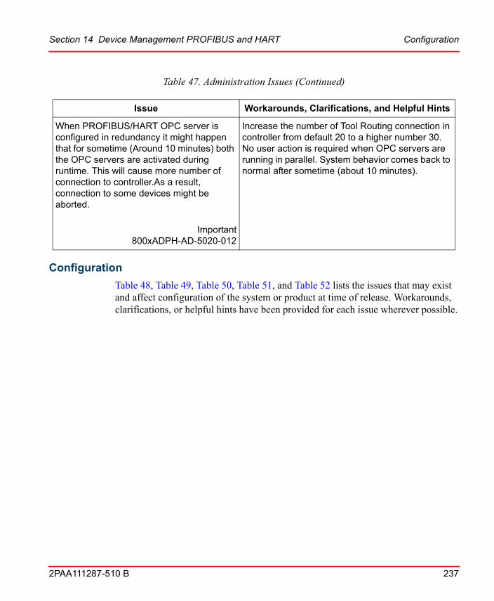
Section 14 Device Management PROFIBUS and HART Configuration
2PAA111287-510 B 237
Configuration
Table 48, Table 49, Table 50, Table 51, and Table 52 lists the issues that may exist and affect configuration of the system or product at time of release. Workarounds, clarifications, or helpful hints have been provided for each issue wherever possible.
When PROFIBUS/HART OPC server is configured in redundancy it might happen that for sometime (Around 10 minutes) both the OPC servers are activated during runtime. This will cause more number of connection to controller.As a result, connection to some devices might be aborted.
Important800xADPH-AD-5020-012
Increase the number of Tool Routing connection in controller from default 20 to a higher number 30. No user action is required when OPC servers are running in parallel. System behavior comes back to normal after sometime (about 10 minutes).
Table 47. Administration Issues (Continued)
Issue Workarounds, Clarifications, and Helpful Hints

Configuration Section 14 Device Management PROFIBUS and HART
238 2PAA111287-510 B
Table 48. Configuration Issues for Device Management PROFIBUS & HART
Issue Workarounds, Clarifications, and Helpful Hints
1. An Upload executed in the Subscriber System will fail when:
a) The selected structure / object in the Provider System has Device Management PROFIBUS/HART aspects
AND
b) Plant Explorer is NOT open in the Provider System
2. Soft Alarm Service goes in to the error state after system restart if it is launching DeviceManagementServer process while startup.
800xDPH-CN-5100-023
1. Apply workaround as below to resolve the problem.
Keep Plant Explorer open in Provider system when an upload operation is done on Subscriber system.
2. Open the Plant Explorer Workplace on Aspect Server node for which Soft Alarm Service is configured.
Disable and Enable the Soft Alarm Service again. Keep the Plant Explorer Workplace open till Soft Alarm Service goes to service state.
If control entity is reserved by any other user than the logged in user, ABB third party DTMs does not show any DTM view.
800xDPH-CN-5100-017
This is DTM specific Implementation. No workaround available.
When DTM is opened or accessed by right-clicking on Device instance in Control Structure without reserving the entity, the same DTM can not be accessed again with user role 'Planning Engineer' after reserving the entity.
800xDPH-CN-5100-029
Close and reopen the Plant Explorer Workplace and then access the DTM with entity reserved.
or
Before accessing the DTM, release the Control project from Controller level and reserve it again.

Section 14 Device Management PROFIBUS and HART Configuration
2PAA111287-510 B 239
Applicable for Pepperl+Fuchs Advanced Diagnostics Module (ADM) -DP object type:When the DTM is opened as a separate window and if the window is maximized after moving scroll bar, then some part of the DTM view will not be visible.
800xDPH-CN-5100-010
If such a problem occur, user needs to close and reopen the aspect view.
Applicable for Pepperl+Fuchs Advanced Diagnostics Module (ADM) -DP object type:Multiple Port objects having large number of P+F Advanced Diagnostics Module (ADM) DTM, when dragged and dropped to another FDS object, FDS DTM topology may not get updated completely with all new dropped port objects. Also, dragged objects will not be shown under original FDS DTM. In such situation, upon closing 800xA Workplace, the recent changes will not be saved and results in multiple Device Management Server processes.
800xDPH-CN-5100-012
Do not use drag and drop functionality with P&F DTM objects. However, if such situation occurs, follow the below steps:
1. Stop Device Management Server process using Task Manager.
2. In Control Structure, delete port objects which are not updated in FDS DTM topology and recreate them using BDM tool.
Table 48. Configuration Issues for Device Management PROFIBUS & HART (Continued)
Issue Workarounds, Clarifications, and Helpful Hints

Configuration Section 14 Device Management PROFIBUS and HART
240 2PAA111287-510 B
Applicable for Pepperl+Fuchs Advanced Diagnostics Module (ADM) -DP object type:If any Configuration/Parameter changes aredone on one instance of P&F DTM, changes will not be shown or updated in instance of same DTM on another node, if already open, unless Frame Application is closed and reopened on second node.
800xDPH-CN-5100-013
To see Configuration/Parameter changes,
1. Close the Frame Application on second node.
2. Reopen Frame Application.
3. Launch the DTM.
Deploy while branch is online at the same node is not possible
A Deploy while fieldbus subtree is online at the same node generates an error message: "This action is not possible..... is online".
800xDPH-CN-5020-005
End running online operation and try Deploy again.
Table 48. Configuration Issues for Device Management PROFIBUS & HART (Continued)
Issue Workarounds, Clarifications, and Helpful Hints

Section 14 Device Management PROFIBUS and HART Configuration
2PAA111287-510 B 241
Inconsistent data after re-configuration of the OPC Server PROFIBUS/HART
After re-configuration of the OPC Server PROFIBUS/HART the server deliver inconsistent data, e.g. wrong quality state if the time stamp of the server topology file is not equal or newer than the re-configuration accomplishing time.
The re-configuration accomplishing time is displayed in the Fieldbus Management dialog and the topology file “TopologyImExport.xml” is saved in the folder “C:\Program Files\ABB Industrial IT\Engineer IT\FieldbusBuilder\OPCServerConfig”.
Important800xDPH-CN-5020-010
After re-configuration (e.g. changes in the topology) of the OPC Server PROFIBUS/HART perform a restart of the OPC Server:
1. Disable the Service Provider for the OPC Server PROFIBUS/HART in the Service Structure. Note that shutdown of the OPC Server PROFIBUS/HART takes time (3-4 minutes)
2. Ensure that both processes - abbfdtopc.exe - abbsrvcc800xA.exe are terminated
3. After that enable the Service Provider for the OPC Server PROFIBUS/HART in the Service Structure again.
While working with HART Mux Connect, the aspects may disappear on some objects.
800xDPH-CN-5100-001
Navigate to some other object and come back or close the Plant Explorer and open again.
Last restore information (Date and timestamp) in FBB Filesync Helper aspect is not available.
800xADPH-CN-5100-002
No impact on functionality. Check configuration wizard log file for this information.
Table 48. Configuration Issues for Device Management PROFIBUS & HART (Continued)
Issue Workarounds, Clarifications, and Helpful Hints

Configuration Section 14 Device Management PROFIBUS and HART
242 2PAA111287-510 B
If the system is upgraded to version 5.1 Rev B, the Calibration Event List aspect may be available on Control Network object instance and ABB Generic HART Transmitter object instances in Control Structure. If DMS Calibration Connect System Extension is not loaded, then this aspect will remain unconfigured.
From 800xA system version 5.1 onwards, due to unconfigured calibration event list aspect, following issues can occur:
1. If such aspect is present in any object, then it will not be possible to browse 800xA OPC server (AfwOpcDaSurrogate). For more information, refer to Product Bulletin 3BSE066045.
2. Consistency checker tool will also report the error about unconfigured calibration event list aspect.
3. When user clicks on Calibration Event List aspect, it opens with following message:
"Could not connect to the configuration aspect. Please look at the configuration"
However, user will not find any configuration to look at.
800xADPH-CN-5100-005
If DMS Calibration Connect is not in use, delete Calibration Event List aspect from Control Network object instance and ABB Generic HART transmitter object instance in Control Structure.
Table 48. Configuration Issues for Device Management PROFIBUS & HART (Continued)
Issue Workarounds, Clarifications, and Helpful Hints

Section 14 Device Management PROFIBUS and HART Configuration
2PAA111287-510 B 243
Replacing IO module in Control Builder M by using Replace Unit menu option cause the problem such as Device Management aspect referring to old IO Module DTM or Invalid topology data. DTM out of order? message in Fieldbus Management aspect of the replaced IO module.
800xDPH-CN-5100-031
Delete the IO module instance and Insert Unit as required.
Selecting Documentation menu for Generic HART DTM does not open user manual. This problem occurs only on the system upgraded from any 800xA System version on 32 bit operating system to 64 bit operating system with device instance created prior to system upgrade.
800xDPH-CN-5100-021
Apply the below mentioned workaround to all the device instances to resolve the problem.
1. Select Configuration user interface from Device Management aspect or from Device Functions menu for a device instance.
2. In Configuration user interface, select the Documentation tab.
3. Browse and select the correct path for Documentation Link as (C:\Program Files(x86)\ABB Industrial IT\Engineer IT\DTM\Basic HART DTM\Doc\3BDD011939-510_A_en_Device_Management_Basic_HART_DTM_5.2.pdf)
4. Click OK or Apply to save the changes.
Table 48. Configuration Issues for Device Management PROFIBUS & HART (Continued)
Issue Workarounds, Clarifications, and Helpful Hints

Configuration Section 14 Device Management PROFIBUS and HART
244 2PAA111287-510 B
S800 I/O DTM
HART Multiplexer Connect
Table 49. Configuration Issues for S800 I/O DTM
Issue Workarounds, Clarifications, and Helpful Hints
In Control Builder M it is possible to move already placed modules from one slot to another slot, but the opened identification view of S800 DTM is not updated. It still shows the old position.
800xDPH-CN-5000-012
Close and reopen the S800 DTM user interface.
The Observer GUI of the AI830 DTM is not displaying the channel value, bar graph for the channels configured with all available signal ranges.
800xADPH-CN-5100-027
There is no workaround for this problem.
Table 50. Configuration Issues for HART Multiplexer Connect
Issue Workarounds, Clarifications, and Helpful Hints
Different HART Multiplexers below the HART Multiplexer Subnet in the Plant Explorer’s Control Structure can be configured with the same name. As a result the user can do allocation errors.
800xDPH-CN-5000-016
Double names do not result in errors, but may lead to identification problems. Therefore use unique names.

Section 14 Device Management PROFIBUS and HART Operation
2PAA111287-510 B 245
Generic HART DTM
Wireless HART
Operation
Table 53, Table 54, Table 55, Table 56, Table 57, and Table 58 lists the issues that may exist and affect operation of the system or product at time of release.
When clicking on 'Multiplexer Assignment' in the HART Multiplexer DTM of HART Multiplexer Connect the expected DTM Windows may not appear.
800xDPH-CN-5000-038
The window for the Assignment is appearing in the Windows Taskbar (background).
Table 51. Configuration Issues for Generic HART DTM
Issue Workarounds, Clarifications, and Helpful Hints
License entry in Generic HART DTM is not available (Browse button is disabled).
800xDPH-CN-5100-003
Contact ABB technical support if license for Generic HART DTM is required.
Table 52. Configuration Issues for Wireless HART
Issue Workarounds, Clarifications, and Helpful Hints
Wireless HART solution for wired HART positioner is not available.
800xDPH-CN-5100-004
Currently, the solution is available only for Wired HART Transmitters and Wireless HART Devices.
Table 50. Configuration Issues for HART Multiplexer Connect (Continued)
Issue Workarounds, Clarifications, and Helpful Hints

Operation Section 14 Device Management PROFIBUS and HART
246 2PAA111287-510 B
Workarounds, clarifications, or helpful hints have been provided for each issue wherever possible.
General
Table 53. General Operational Issues
Issue Workarounds, Clarifications, and Helpful Hints
The Device Type Manager (DTM) for ABB Instruments (except S800 IO, S900 IO and Basic HART DTM) does not up-/download the complete parameter data-set, if the up-/download is started via Fieldbus Management Aspect.
800xDPH-OL-5000-019
Complete up-/download of device parameter data-set must be initiated directly in the specific DTM. Open the DTM of the specific device, change the parameter (if applicable) and start download/upload from the DTM menu.
Disable Communication via Fieldbus Management aspect while an online DTM window is still open may result in failed release communication call.
800xADPH-OL-5000-035
Close all open online DTM windows before disabling the communication via Fieldbus management aspect.
If a project is taken over from another node or the Load-Evaluate-Go action is performed, then several communication related error messages (for example, ..communication failed..) are displayed.
800xDPH-OL-5010-001
Take Over a project from another node or Load- Evaluate-Go should only performed if the Fieldbus Management is in Communication disabled mode (offline).

Section 14 Device Management PROFIBUS and HART Operation
2PAA111287-510 B 247
The generic HART Asset Monitor loaded in the AO Server could show an inconsistency condition for Configuration Changed.
The Configuration Changed condition in the generic HART Asset Monitor is active, but there was no change in the device configuration via DTM or handheld.
The Configuration Changed condition is not reset, if the device and the instance data set has been synchronized.
800xDPH-OL-5010-003
Open Plant Explorer Workplace Aspect System Structure with system administrator rights.
Navigate to Asset Monitoring, Aspect system -> Asset Monitors, Aspect type. -> HART Generic Device Asset Monitor, Aspect category.
Select the aspect “HART Generic Device Asset Monitor”.
Open the tab "Input Records" and set for all optional input records in the column “Data Source Aspect” the entry to "None".
Confirm the changes with Apply button.
Control structure out of sync message while working with DTMs specially when using Wireless HART or HART Multiplexer connect.
800xADPH-OL-5100-001
If you get such message close plant explorer, wait for 2 minutes and then open again
Sometimes there may be an entry 'Invalid item ID' in Eventlist after performing
operations on Fieldbus Management aspect eg.Upload or Download.
800xADPH-OL-5100-009
These messages have no impact on Functionality of Fieldbus Builder P/H. Ignore the messages.
It is observed that if Online DTM GUI is kept open for a longer time, DeviceManagementServer process crashes.
800xADPH-OL-5100-021
It is recommended to close the DTM GUI after usage.
If this issue occurs, close and reopen the Plant Explorer Workplace.
Table 53. General Operational Issues (Continued)
Issue Workarounds, Clarifications, and Helpful Hints
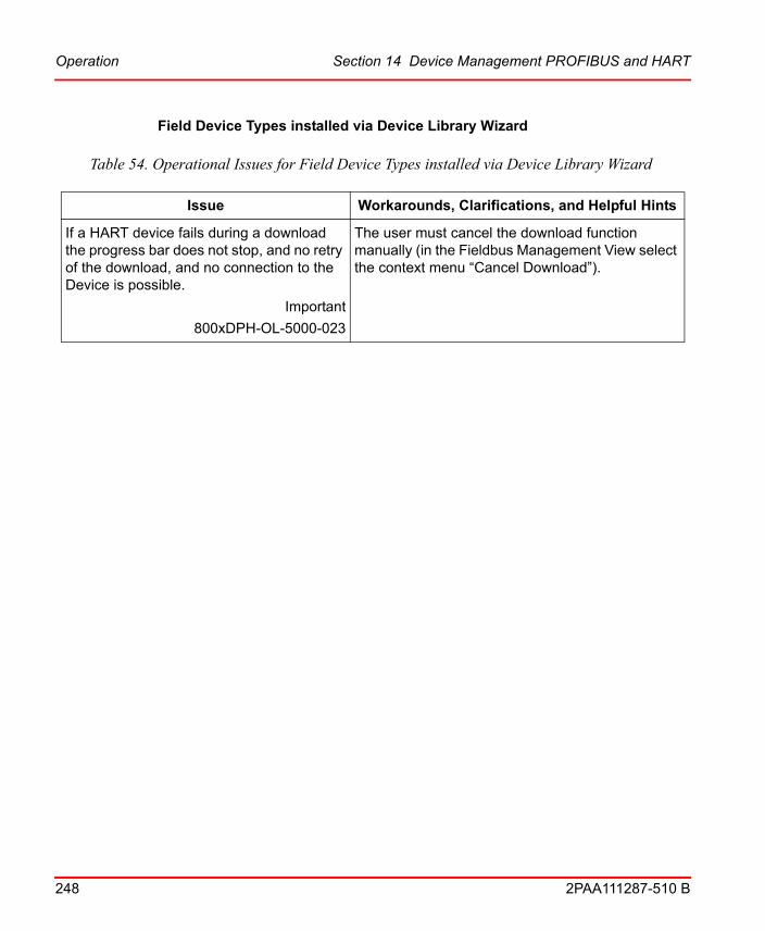
Operation Section 14 Device Management PROFIBUS and HART
248 2PAA111287-510 B
Field Device Types installed via Device Library Wizard
Table 54. Operational Issues for Field Device Types installed via Device Library Wizard
Issue Workarounds, Clarifications, and Helpful Hints
If a HART device fails during a download the progress bar does not stop, and no retry of the download, and no connection to the Device is possible.
Important
800xDPH-OL-5000-023
The user must cancel the download function manually (in the Fieldbus Management View select the context menu “Cancel Download”).

Section 14 Device Management PROFIBUS and HART Operation
2PAA111287-510 B 249
Enabling communication at a Fieldbus Management aspect sometimes does not work
Some DTMs which are opened via configuration menu do not allow parallel communication via a Fieldbus Management aspect. An error message in form of: “Set Communication failed” will pop-up.
800xDPH-OL-5020-009
Close all DTM windows before enabling communication.
Following two issues may occur with Basic HART DTM:
1. If disable communication is selected from Fieldbus Management aspect while working with Basic HART DTM, an abort message may appear.
2. Cancel upload or disable communication through Fieldbus Management aspect may cause communication issue in next online transaction. Communication issue occurs if Fieldbus Management aspect view is closed by user or initiated next online operation from Fieldbus Management view of same DTM before progress bar disappears.
800xDPH-OL-5100-014
1. Ignore the abort message.
2. Wait till progress bar disappear before closing the Fieldbus Management aspect view.
Table 54. Operational Issues for Field Device Types installed via Device Library Wizard
Issue Workarounds, Clarifications, and Helpful Hints

Operation Section 14 Device Management PROFIBUS and HART
250 2PAA111287-510 B
Wireless HART
Table 55. Operational Issues for Wireless HART
Issue Workarounds, Clarifications, and Helpful Hints
In case Wireless HART Gateway is power recycled, all the adapters may not join the network afterwards.
Important800xDPH-OL-5100-003
Power recycle the adapters which do not join the network.
Sometimes two wired HART devices may appear under one Adapter in Gateway Webpage. This might happen after replacing the wired device under the adapter or moving it to another adapter.
Important800xDPH-OL-5100-004
Delete the devices in Gateway Webserver which are not physically connected to the Wireless HART Adapter.
Following general limitations of Pepperl + Fuchs Wireless HART Gateway should be
considered:
1. Gateway communication via RS485 serial interface not supported. This means
MODBUS RTU /Binary HART over RS485 connectivity is not possible.
2. Gateway webserver is supported from Internet Explorer version 8.0 onwards.
3. DHCP/DNS client functionality will not be supported. Only manual configuration of
Gateway IP address is supported.
800xDPWH-OL-5100-013
Observe these limitations.

Section 14 Device Management PROFIBUS and HART Operation
2PAA111287-510 B 251
PROFIBUS HART
HART Multiplexer
Generic HART
Table 56. Operational Issues for PROFIBUS HART
Issue Workarounds, Clarifications, and Helpful Hints
Windows Event list is filled by the GPB DTM.
800xDPH-OL-5100-012
The DTM Events will fill the information Event. Ignore the entries or filter them out.
Table 57. Operational Issues for HART Multiplexer
Issue Workarounds, Clarifications, and Helpful Hints
While working with HART Multiplexer DTMs, the List of Multiplexer User interface is not automatically updated if there is a disturbance. Eg.COM port is disconnected.
800xDPH-OL-5100-011
This problem is with update of DTM User interface and refreshing the Multiplexer list will show the correct status of Multiplexers. However there is no issue with Device DTM and Asset Optimization communication.
Table 58. Operational Issues for Generic HART
Issue Workarounds, Clarifications, and Helpful Hints
When working with Generic HART DTM, if plant Explorer is closed, while DTM GUI is still open in Online mode, then there may be an entry in PPA alarm and event list as 'Abort'.
800xADPH-OL-5100-005
Ignore the message.

Miscellaneous Section 14 Device Management PROFIBUS and HART
252 2PAA111287-510 B
Miscellaneous
Table 59 list the problems or issues known to exist with the current release that do not fit into one of the other categories. Workarounds, clarifications, or helpful hints have been provided for each issue wherever possible.
Table 59. Miscellaneous Issues
Issue Workarounds, Clarifications, and Helpful Hints
Redundancy switch over of a Connectivity Server leads to “bad status” in the corresponding Asset Monitors for one OPC Server cycle.
800xADPH-MS-5010-002
Good values are available from second OPC cycle onwards.
In Generic HART DTM Force window, If user sets to exceed lower / upper range values then Popup window should appear but it's not appearing.
800xADPH-MS-5010-003
When user sets value which exceed the lower / upper range values and press apply button, no message box pops up.But in the status bar it shows a message "No HART message received".The value then goes back to last valid value and user can continue with normal operations
Aspects of device instances created from device type objects will not be updated, if a new minor version of the device type object is installed via Device Library Wizard.
800xADPH-MS-5000-032
Device Type instances will be updated with functional aspects like Device Management aspects only. The device types can not be recognized directly via name or type definition aspects.

Section 14 Device Management PROFIBUS and HART Miscellaneous
2PAA111287-510 B 253
After upgrade from previous 800xA system version less then SV5.0 the HART Generic Actuator and the HART Generic Transmitter device types in the Plant Explorers Object Type Structure includes DMS aspects.
If the user instantiates a HART Generic Actuator or a HART Generic Transmitter in the Plant Explorers Control Structure, DMS aspects are available, even, if the connected device is not supported by DMS.
800xADPH-MS-5000-034
Remove the DMS aspects manually.
There have been no problems observed, if the device is linked into DMS, even if the connected device type does no support DMS functions.
Table 59. Miscellaneous Issues (Continued)
Issue Workarounds, Clarifications, and Helpful Hints

Miscellaneous Section 14 Device Management PROFIBUS and HART
254 2PAA111287-510 B
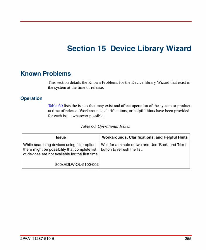
2PAA111287-510 B 255
Section 15 Device Library Wizard
Known ProblemsThis section details the Known Problems for the Device library Wizard that exist in the system at the time of release.
Operation
Table 60 lists the issues that may exist and affect operation of the system or product at time of release. Workarounds, clarifications, or helpful hints have been provided for each issue wherever possible.
Table 60. Operational Issues
Issue Workarounds, Clarifications, and Helpful Hints
While searching devices using filter option there might be possibility that complete list of devices are not available for the first time.
800xADLW-OL-5100-002
Wait for a minute or two and Use 'Back' and 'Next' button to refresh the list.

Operation Section 15 Device Library Wizard
256 2PAA111287-510 B
Deletion of device types will result in orphaned object types when device types instances are directly used in any structure other than Control structure.
DLW will list such device types as deletable device types as it searches only to control structure if device type has been in use.
800xADLW-OL-5100-003
In such cases delete device types manually and don’t use DLW delete functionality.
DLW will list PROFIBUS libraries as deletable library even if the PROFIBUS library is just connected in Control builder and actually not being used.
800xADLW-OL-5100-004
Actual Delete will not be possible in this case. Disconnect the library first in Control builder and then use DLW delete functionality.
Table 60. Operational Issues (Continued)
Issue Workarounds, Clarifications, and Helpful Hints

2PAA111287-510 B 257
Section 16 Asset Optimization
Known ProblemsThis section details the Known Problems for Asset Optimization, that exist in the system at the time of release.
Installation
Table 61 lists issues that may exist and affect the installation and upgrade of the system or product at time of release. Workarounds, clarifications, or helpful hints have been provided for each issue wherever possible.

Installation Section 16 Asset Optimization
258 2PAA111287-510 B
Table 61. Installation Issues
Issue Workarounds, Clarifications, and Helpful Hints
The following error is observed during Asset Optimization software installation on the AO Server Node, while installing the COM+ Components:
Couldn’t register COM+ Component….
At the same time following events are logged in the Windows Application Event Log.
Faulting application MsiExec.exe, version 4.5.6002.18005, time stamp 0x49e01c42, faulting module OptaoClientUtils.dll_unloaded….
800xAASO-OL-5102-001
This issue is observed in rare instances, perform the following steps to solve this problem:
1. Click OK to acknowledge the message and continue with the installation of the remaining products using the System Update Tool.
2. After completing the installation,
• Start > Control Panel > Programs and Features.
• Select ABB Asset Optimization software and click Uninstall.
• Select Remove from the installation dialog box and complete the uninstallation of the software.
3. Locate the Asset Optimization software in the DVD. The software is available in the following location.
//Asset Optimization / Asset Optimization Server & Client
4. Run Setup.exe.
5. Select Server from the Setup Type dialog box and complete the installation.

Section 16 Asset Optimization Configuration
2PAA111287-510 B 259
Configuration
Table 62 lists the issues that may exist and affect configuration of the system or product at time of release. Workarounds, clarifications, or helpful hints have been provided for each issue wherever possible.
The following error may be observed during upgrade from 800xA 3.1 SP3 to 800xA 5.0 SP2:
Running upgrade phase 'Backup Data Restored' for Asset Optimizer Server ...** Aspect Hook Error **
This error results in a Basic Service Group object created at the same level as the Services object in the Service Structure.
800xAASO-IN-5010-001
Delete the Basic Service Group for OptaoStartup.
Table 62. Configuration Issues
Issue Workarounds, Clarifications, and Helpful Hints
If an incorrectly configured Asset Monitor Data Source is (or was) used by a loaded Asset Monitor, an Asset Optimization Server will report the following error message:
“AM Engine Running, DataSources Status: ‘Asset Optimization:BAD Asset Monitor Data Source’ data source error, will try to reconnect in one minute.”
800xAASO-CN-5000-006
Perform one of the following:
• Properly configure the Asset Monitor Data Source and reload the Asset Monitor using it.
• If no Asset Monitors are configured to use the improperly configured Asset Monitor Data Source, perform a Load all AMs operation from the Asset Monitors tab of the Asset Optimization Server aspect. This will remove the improperly configured Asset Monitor Data Source from the Asset Optimization Server.
There will be no further retry of connection to unused dataserver(s) by data engine.
Table 61. Installation Issues (Continued)
Issue Workarounds, Clarifications, and Helpful Hints

Operation Section 16 Asset Optimization
260 2PAA111287-510 B
Operation
Table 63 lists the issues that may exist and affect operation of the system or product at time of release. Workarounds, clarifications, or helpful hints have been provided for each issue wherever possible.
Table 63. Operational Issues
Issue Workarounds, Clarifications, and Helpful Hints
When an equipment ID or Asset Monitor aspect is changed after fault report defaults are created, the changes are not updated in the fault report defaults.
Important800xAASO-OL-5100-001
Recreate the fault report defaults.
After update/upgrade, sometimes it is observed that the Asset Viewer propagated status shows last updated status for objects with Asset Monitor that are inserted into the Asset Structure.
800xAASO-OL-5140-010
Re-insert those Objects having Asset Monitors or restart the AssetTree service located in the Service Structure.
To restart:
1. Under Service Structure, Service, go to AssetTree, Service and then expand AssetTree SG_1, Service Group.
2. Click AssetTree SP_1, Service Provider.
3. Select Service Provider Definition from the Aspect list on the right-hand pane.
4. Clear the selection in Enabled check box to disable and then check it again to restart the AssetTree Service.

2PAA111287-510 B 261
Section 17 PC, Network and SoftwareMonitoring
Known ProblemsThis section details the Known Problems for PC, Network and Software Monitoring that exist in the system at the time of release. It also enumerates known problems encountered in the final testing of this product release and identifies workarounds that help overcome the problem.
Configuration
Table 64 lists the issues that may exist and affect configuration of the system or product at time of release. Workarounds, clarifications, or helpful hints have been provided for each issue wherever possible.
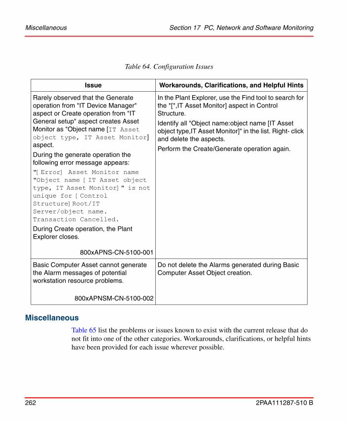
Miscellaneous Section 17 PC, Network and Software Monitoring
262 2PAA111287-510 B
Miscellaneous
Table 65 list the problems or issues known to exist with the current release that do not fit into one of the other categories. Workarounds, clarifications, or helpful hints have been provided for each issue wherever possible.
Table 64. Configuration Issues
Issue Workarounds, Clarifications, and Helpful Hints
Rarely observed that the Generate operation from "IT Device Manager" aspect or Create operation from "IT General setup" aspect creates Asset Monitor as "Object name [IT Asset object type, IT Asset Monitor] aspect.
During the generate operation the following error message appears:"[Error] Asset Monitor name "Object name [IT Asset object type, IT Asset Monitor]" is not unique for [Control Structure]Root/IT Server/object name. Transaction Cancelled.
During Create operation, the Plant Explorer closes.
800xAPNS-CN-5100-001
In the Plant Explorer, use the Find tool to search for the *[*,IT Asset Monitor] aspect in Control Structure.
Identify all "Object name:object name [IT Asset object type,IT Asset Monitor]" in the list. Right- click and delete the aspects.
Perform the Create/Generate operation again.
Basic Computer Asset cannot generate the Alarm messages of potential workstation resource problems.
800xAPNSM-CN-5100-002
Do not delete the Alarms generated during Basic Computer Asset Object creation.

Section 17 PC, Network and Software Monitoring Miscellaneous
2PAA111287-510 B 263
Table 65. Miscellaneous Issues
Issue Workarounds, Clarifications, and Helpful Hints
When upgrading an older system version to System Version 5.1 on running the consistency check error on PNSM object types, the following error is observed " Library key is missing on 'Light Generic Computer Process: General Computer Nodes Reference'
800xAPNS-MS-5100-001
Workaround: Ignore this error, this will not impact PNSM functionality.
Alternatively it is also possible to fix this error by deleting the "General computer nodes reference" aspect from the Light Generic Computer Process Object type.

Miscellaneous Section 17 PC, Network and Software Monitoring
264 2PAA111287-510 B

2PAA111287-510 B 265
Section 18 Batch Management
Known ProblemsThis section details the Known Problems for Batch Management, that exist in the system at the time of release.
Configuration
Table 66 lists the issues that may exist and affect configuration of the system or product at time of release. Workarounds, clarifications, or helpful hints have been provided for each issue wherever possible.
Operation
Table 67 lists the issues that may exist and affect operation of the system or product at time of release. Workarounds, clarifications, or helpful hints have been provided for each issue wherever possible.
Table 66. Configuration Issue
Issue Workarounds, Clarifications, and Helpful Hints
Oracle (Information Manager) returns an error when a Batch recipe operation tries to use the same history association name (logical name) that another operation in the recipe has already used. This operation is not started.
Important800xAPMB-CN-5020-003
Ensure that unique logical names are used in recipes. These logical names can be created dynamically using Batch expressions.

Operation Section 18 Batch Management
266 2PAA111287-510 B
Table 67. Operational Issues
Issue Workarounds, Clarifications, and Helpful Hints
Modified by column is not updated if the user logs in to PPA using Change User (Log Over change). It always updates this column with the System Logged in user.
800xAPMB-OL-5130-031
Only modify procedures as the initially log on user, if you want the Modified by column to update with the correct username.
Unable to schedule Batch from the Scheduler Aspect as the default cell is unavailable and the Batch cell is invisible in the main view of the Scheduler Aspect.
800xAPMB-OL-5130-035
If the default cell is unavailable for a Procedure, make the Batch Cell field visible from the Config View of the Batch Scheduler Aspect.
Batch_Reports.xls fails to display data from the Reports Tab of Batch Information Window and Batch History Information Window. This issue is observed only in 64-bit versions.
800xAPMB-OL-5130-034
Users have to manually provide the right path to the Batch_fpexcel.xla.
Refer to Procedure to Provide the Path in the Excel Sheet on page 283 for the steps.

Section 18 Batch Management Operation
2PAA111287-510 B 267
Harmony communications can fail to write commands from the Batch Manager to the control logic in the Harmony controller. This failure generates a Batch Alarm. The Batch Recipe will stall on the active block experiencing the communication error and the Recipe Procedure block will turn red indicating an error.
Navigate into the Batch Recipe PFC and select the Block.
Status of the recipe procedure block experiencing the error.
If the block in error is a Compute BMA (Batch Manager Action) use the Start @ Beginning command to retry the compute expression.
If the block in error is a Phase, Open the block status of the Phase in error and select either the Start @ Beginning or Continue @ Next command depending on the error shown in the block status Errors field.
Conditions that indicate the Phase failed to start and a Start@ Beginning Command is needed:
Command = 1 (Start)
Command = 14 (Test Phase)
Command = 15 (Start Sequence)
Command = 16 (Test Sequence)
Command = 31 (Send Phase Data)
Command = 32 (Send Sequence Data)
Conditions that indicate a Continue @ Next command is needed.
Command = 6 (Reset)
Table 67. Operational Issues (Continued)
Issue Workarounds, Clarifications, and Helpful Hints
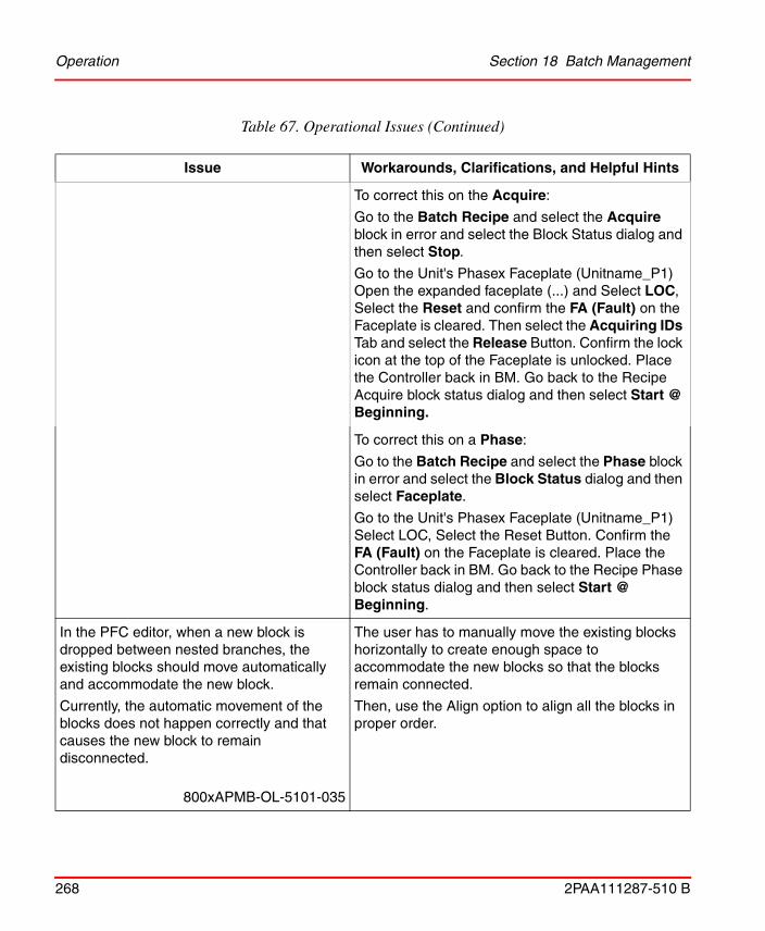
Operation Section 18 Batch Management
268 2PAA111287-510 B
To correct this on the Acquire:
Go to the Batch Recipe and select the Acquire block in error and select the Block Status dialog and then select Stop.
Go to the Unit's Phasex Faceplate (Unitname_P1) Open the expanded faceplate (...) and Select LOC, Select the Reset and confirm the FA (Fault) on the Faceplate is cleared. Then select the Acquiring IDs Tab and select the Release Button. Confirm the lock icon at the top of the Faceplate is unlocked. Place the Controller back in BM. Go back to the Recipe Acquire block status dialog and then select Start @ Beginning.
To correct this on a Phase:
Go to the Batch Recipe and select the Phase block in error and select the Block Status dialog and then select Faceplate.
Go to the Unit's Phasex Faceplate (Unitname_P1) Select LOC, Select the Reset Button. Confirm the FA (Fault) on the Faceplate is cleared. Place the Controller back in BM. Go back to the Recipe Phase block status dialog and then select Start @ Beginning.
In the PFC editor, when a new block is dropped between nested branches, the existing blocks should move automatically and accommodate the new block.
Currently, the automatic movement of the blocks does not happen correctly and that causes the new block to remain disconnected.
800xAPMB-OL-5101-035
The user has to manually move the existing blocks horizontally to create enough space to accommodate the new blocks so that the blocks remain connected.
Then, use the Align option to align all the blocks in proper order.
Table 67. Operational Issues (Continued)
Issue Workarounds, Clarifications, and Helpful Hints

Section 18 Batch Management Operation
2PAA111287-510 B 269
If the Auto-align option is enabled in the PFC editor, when a new block is dropped between nested branches, the existing blocks should align automatically in the horizontal direction.
Currently, the blocks are getting aligned in the vertical direction.
800xAPMB-OL-5101-036
Manually move the existing blocks horizontally, so that the newly dropped blocks get aligned in the horizontal direction.
Procedure align fails to handle a branch with a trivial leg, where a trivial leg is a direct connection between a parallel branch Start and a parallel branch End block, with no intervening blocks between them.
800xAPMB-OL-5101-037
Align the procedure before establishing the connection between the Parallel branch (Start) and Parallel branch (End) blocks.
Workplace stops responding, when Auto Generate Batch ID aspect is selected before Batch services are running.
800xAPMB-OL-5101-038
Kill the process AfwWorkplaceApplication.exe present in the Processes tab of the Windows Task Manager.
Reopen AfwWorkplaceApplication and ensure that Batch services are up and running before accessing the Auto Generate Batch ID aspect.
Table 67. Operational Issues (Continued)
Issue Workarounds, Clarifications, and Helpful Hints

Operation Section 18 Batch Management
270 2PAA111287-510 B
Adding parameter(s) to a phase when the library and applications are not reserved in Control Builder causes the phase parameter to be added to the Object Type of the phase. But, the phase parameter fails to get written to instances. This generates an error message that the parameter could not be added.
When the proper steps are followed after the failure, the same error gets generated.
Important800xAPMB-OL-5101-039
Always reserve the library and application. This will ensure that there are no consistency issues.
The PFC Editor may stop responding while configuring and saving when there are large numbers of blocks.
Important800xAPMB-OL-5101-040
Edit the crashed Procedure. A message Do you want to reload the unsaved changes is displayed.
Click Yes.
Information of all the configured blocks will be reloaded into the editor, except for the last configured block.
The Batch Report displays broken links if Batch software is installed on a drive other than the C drive.
800xAPMB-OL-5101-041
Edit the link to change the source to Batch_Fpexcel to the proper drive and path.
Close the Edit Links dialog box. Press F9 to update the link.
Table 67. Operational Issues (Continued)
Issue Workarounds, Clarifications, and Helpful Hints

Section 18 Batch Management Operation
2PAA111287-510 B 271
While editing multiple attributes in the runtime grid view, if the Limited Low and Limited High are lower or higher than the current InValue, then the grid view is cleared, but the Limited High and Limited Low values get retained.
After this state, if the InValue is changed to a value within the new Limited High and Limited Low and saved, then the cleared values are saved as the new Limited Low or Limited High value.
Important800xAPMB-OL-5101-042
When editing multiple equipment attributes in the runtime grid view, ensure that the Limited Low or Limited High value of the attributes are not edited to a value higher or lower than the current InValue.
When Batch Report in xlsx format is printed from Batch Information or Batch History Information, it does not print an updated Batch Report. However, when a xlsm or xls format of Batch Report is opened for printing, the report gets updated automatically and printed correctly.
800xAPMB-OL-5101-043
When an xlsx format of Batch Report is opened for printing, press F9 key to update the report and then print it.
Or
When creating the Batch Report.xlsx template, ensure that the function Calculation Option is set to the option Automatic.
In the Environment configuration enabled system, a deleted Development Procedure aspect is immediately removed from the view in the Procedure Structure. However, the aspect is deleted (internally) after 10 minutes. During this interval, if a new Development Procedure aspect is created, its procedure data is also deleted.
Important800xAPMB-OL-5100-021
In the Environment configuration enabled system, after deleting the Development Procedure aspect, wait for 15 minutes to create a new Development Procedure aspect in the same Procedure object.
Table 67. Operational Issues (Continued)
Issue Workarounds, Clarifications, and Helpful Hints
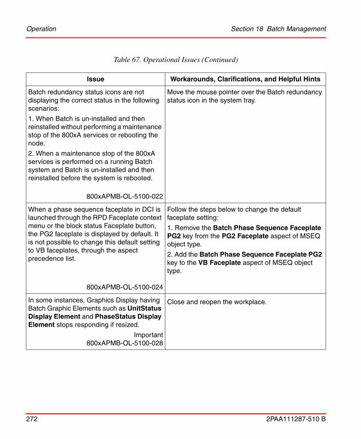
Operation Section 18 Batch Management
272 2PAA111287-510 B
Batch redundancy status icons are not displaying the correct status in the following scenarios:
1. When Batch is un-installed and then reinstalled without performing a maintenance stop of the 800xA services or rebooting the node.
2. When a maintenance stop of the 800xA services is performed on a running Batch system and Batch is un-installed and then reinstalled before the system is rebooted.
800xAPMB-OL-5100-022
Move the mouse pointer over the Batch redundancy status icon in the system tray.
When a phase sequence faceplate in DCI is launched through the RPD Faceplate context menu or the block status Faceplate button, the PG2 faceplate is displayed by default. It is not possible to change this default setting to VB faceplates, through the aspect precedence list.
800xAPMB-OL-5100-024
Follow the steps below to change the default faceplate setting:
1. Remove the Batch Phase Sequence Faceplate PG2 key from the PG2 Faceplate aspect of MSEQ object type.
2. Add the Batch Phase Sequence Faceplate PG2 key to the VB Faceplate aspect of MSEQ object type.
In some instances, Graphics Display having Batch Graphic Elements such as UnitStatus Display Element and PhaseStatus Display Element stops responding if resized.
Important800xAPMB-OL-5100-028
Close and reopen the workplace.
Table 67. Operational Issues (Continued)
Issue Workarounds, Clarifications, and Helpful Hints

Section 18 Batch Management Operation
2PAA111287-510 B 273
While upgrading an existing system to the System Version 5.1, the system overwrites the entire Miscellaneous Configuration aspect in the backup. This removes all the existing Batch IDs and the stored settings in the Miscellaneous Configuration aspect.
In addition, some incorrect Batch IDs are also loaded as part of Miscellaneous Configuration. The incorrect Batch IDs will also appear in a newly created system.
Important800xAPMB-OL-5100-031
Restored system:
Export the Miscellaneous Configuration aspect from the [Library Structure]BatchManagement/Configuration object in the backed up system.
Import the Miscellaneous Configuration aspect, after restoring the system.
New system:
Identify the incorrect Batch IDs and remove them manually.
For Batch interfacing with DCI systems, Batch IDs having more than 20 characters cause a time-out condition to be generated by the Batch manager when tying to execute the procedure.
800xAPMB-OL-5100-032
Always ensure the Batch IDs have less than 21 characters.
Batch equipment and phase templates do not work after a Version 3.1 SP3 800xA System is restored on a Version 5.0 SP2 800xA System.
Important800xAPMB-OL-5020-028
1. Delete the MainFaceplate and/or MainFaceplate_Pre50 aspects from each phase type in all user libraries (Object Type Structure/ Object Type/AC800 M/C Connect/Libraries/ user_library/Control Module Types/phase_types).
2. Copy the MainFaceplate aspect from Object Type Structure/Object Type/AC800 M/C Connect/Libraries/BatchAdvTemplatesLib/Control Module Types/PhaseTemplate object to each phase type in all user libraries.
Table 67. Operational Issues (Continued)
Issue Workarounds, Clarifications, and Helpful Hints

Operation Section 18 Batch Management
274 2PAA111287-510 B
If Batch Equipment (Units) and Equipment Group objects are deleted from a system and then the same objects are imported back into the system (from an .afw file), procedures that reference these deleted objects will not execute properly. Control recipe execution failure modes will vary based upon the specific circumstances.
Important800xAPMB-OL-5000-026
If the Batch application has been installed in a redundant configuration and the secondary Batch server is active and synchronized, force a failover to secondary server node operation to allow the affected procedures to execute properly. The former primary Batch Server should then be restarted and established as the secondary Batch Server using the standard published instructions.
If the Batch application has been installed in a non-redundant configuration (or the secondary Batch server is not available), it is necessary to stop the Batch Services, shutdown and restart the Batch Server and restart Batch services to allow the affected procedures to execute properly.
The error message Failed to get Batch ID aspect interface is encountered when using the Batch Web Service Interface. Users are unable to schedule Unit and Operation Batch Procedures.
800xAPMB-OL-5110-004
To schedule these procedures, the users need to add a Batch ID aspect to the unit and operation procedures. This is required regardless of using the auto generate functionality.
Poor usage of memory by bmsAddValue results in the recipe editor running out of memory. This happens while recipe is saved with 3000 parameters.
800xAPMB-OL-5102-044
Allocate more memory to reduce reallocate frequency.
Table 67. Operational Issues (Continued)
Issue Workarounds, Clarifications, and Helpful Hints

Section 18 Batch Management Operation
2PAA111287-510 B 275
When attempting to schedule a Batch using batch_sbatch for a procedure that has the same name as another procedure, the following error will appear and the schedule call will fail:
Errors:
Specified recipe does not exist.
800xAPMB-CN-5024-010
To identify duplicate named procedures, the path to the procedure must be specified as mentioned in the following example:
batch_sbatch -b BID -r PathToProcedure/ProcedureName.
Recipes containing Sequence Start and Sequence End Blocks that were created or edited in 5.1 and 5.1 Rev A versions will have an incorrect Start ID on the Phase Blocks. This will cause the recipe to fail if a "Start from Beginning" is used.
Sequence Start and Sequence End blocks are only used with DCI and Harmony Batch Connects. This issue does not apply to other Connects like AC 800M, MOD 300 and Melody.
800xAPMB-OL-5102-045
If the recipe was created in any version prior to 5.1 and not modified, no actions are required.
1. Select the Procedure and Edit the Procedure.
2. Make any type of edit to enable a save button.
3. Save the recipes and Approve.
Now the Phase Sequence Start ID will be saved for all the phases between the Sequence Start and Sequence End.
Unable to add new units to the system as the license count is incorrect during configuration.
800xAPMB-OL-5102-046
Fail over or reboot the Batch Server. This will correct the license count and will allow the user to add new units.
Table 67. Operational Issues (Continued)
Issue Workarounds, Clarifications, and Helpful Hints

Operation Section 18 Batch Management
276 2PAA111287-510 B
In the versions prior to 5.0, the “Event Attribute Object Extension” aspect is present in the Service Structure under the Alarm Manager. For version 5.0 and greater, these are not required. Leaving these entries in place will cause the Alarm Events data (report) to have redundant entries.
800xAPMB-OL-5102-047
These Event Attribute Object Extensions are no longer used for Alarm Management.
Delete all the "Event Attribute Object Extension" aspects.
The system fails to handle the units that are inserted into multiple Structures, if Misc Configuration/Unit Event Association is set to Objects and Descendents (default).
This will lead to multiple events of the same unit present in multiple Structures.
800xAPMB-OL-5102-048
1. Go to Library Structure and Select Configuration Object.
2. In Aspect View, select Miscellaneous Configuration Aspect.
3. In Batch Settings tab, select objects and Descendents in Structure in the combo box and select the Control structure and then click Apply.
Caution: If you have event generating objects and descendents in any other Structure than the Control Structure, they will be lost.
Installing of Batch Clients/Servers on a machine acting as the Domain Controller may cause netRouter to stop working.
800xAPMB-OL-5102-049
Do not install Batch Clients/Servers on a machine acting as the Domain Controller.
The Runtime Edit version number does not increment while users perform multiple Runtime Edit on a procedure.
800xAPMB-OL-5102-081
No workaround exists for this issue.
Table 67. Operational Issues (Continued)
Issue Workarounds, Clarifications, and Helpful Hints

Section 18 Batch Management Operation
2PAA111287-510 B 277
Operational changes in the Runtime Edit dialog is saved despite users click Cancel Runtime Edit.When Runtime Edit is selected at the same procedure level, it displays the changes that were done during the previous Runtime Edit.
800xAPMB-OL-5102-082
No workaround exists for this issue.
The expression “gets” is used to get the current data value for a specified OPC item. If a string OPC item is used with the “gets” expression the returning value will always be 0.0.
There is no indication that the expression type was wrong for the value it was trying to obtain. There are no error messages.
800xAPMB-OL-5102-112Product Bulletin: 3BUA002978
The “gets” expression does function correctly when used with the correct data type.
Confirm and test that the correct data type is being used with the “gets” expression. Use “gets” for OPC string items.
Melody phase driver collects the output parameters in Completed and Aborted states only.
800xAPMB-OL-5104-089
No workaround exists for this issue.
Out Value of Batch phase parameters are not captured in the standard Excel “Batch report Template”.
800xAPMB-OL-5120-112
This problem is intermittent, try rerunning the report until the values are updated.
Table 67. Operational Issues (Continued)
Issue Workarounds, Clarifications, and Helpful Hints

Operation Section 18 Batch Management
278 2PAA111287-510 B
Operator inputs are not showing up in the audit trail events for the category “Batch Operator Actions”.
800xAPMB-OL-5131-112
This issue has been corrected.
The Long Message field of the Audit Trail Event messages, now includes the batch operator actions. This is the same information supplied in the Long Message field of the Block Status event message.
When a user defined Batch function contains a line continuation character (\) and is locked using Function locking, the function fails to run when called from a recipe.
The block containing the call goes into error. The error reported on the Block Status varies, but can include Syntax Error or Stack Underflow.
800xAPMB-OL-5130-093800xAPMB-OL-5104-090
Remove line continuation characters from the function or do not lock the function.
In the Procedure Structure of PPA, system stops responding and may crash if reference to one of the Procedure Object is inserted under the same Object and is kept empty.
800xAPMB-OL-5130-094800xAPMB-OL-5104-091
Delete the lower Empty Procedures Object.
When an expression is configured on a Procedure parameter and if Access level of this Procedure parameter is changed at the lower level, then the change is not be reflected at the upper level.
800xAPMB-OL-5130-095800xAPMB-OL-5104-092
Access levels are not inherited from their lower levels when they are created. Changes to the Access level must be done on all the recipe instances.
Table 67. Operational Issues (Continued)
Issue Workarounds, Clarifications, and Helpful Hints

Section 18 Batch Management Operation
2PAA111287-510 B 279
Phase parameters in Procedure reports are ordered alphabetically. There is no option to order them by user entry order.
800xAPMB-OL-5130-097800xAPMB-OL-5104-093
No workaround exists for this issue.
When an AFW file that contains Batch units fails to import, the license count for the Batch units is incremental even though the units fail to load in the system.
The incorrect count of units will then limit the number of Batch units that can be added to the system after the failed import.
800xAPMB-OL-5130-099800xAPMB-OL-5104-094
Restart the Batch Services (or reboot the Batch Server) to establish the correct Batch unit license count.
Deleting a Batch Cell while batch recipes are scheduled under that batch cell will cause the recipes to no longer be displayed in the Batch Overview dialog.
800xAPMB-OL-5140-125
There is no workaround.
Users should not delete the Batch Cell if there are associated batches scheduled with that cell.
Batch procedure Print/view functionality does not work as expected when the procedure object path has more than 127 characters.
800xAPMB-OL-5140-124
The software has been corrected to handle up to 256 characters and error handling is improved with proper message.
Table 67. Operational Issues (Continued)
Issue Workarounds, Clarifications, and Helpful Hints
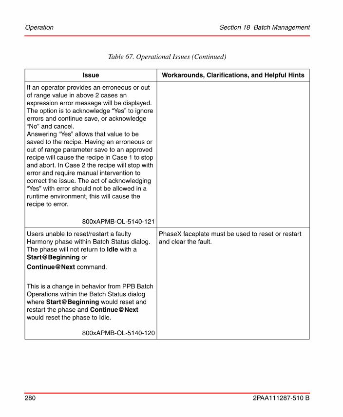
Operation Section 18 Batch Management
280 2PAA111287-510 B
If an operator provides an erroneous or out of range value in above 2 cases an expression error message will be displayed. The option is to acknowledge “Yes” to ignore errors and continue save, or acknowledge “No” and cancel. Answering “Yes” allows that value to be saved to the recipe. Having an erroneous or out of range parameter save to an approved recipe will cause the recipe in Case 1 to stop and abort. In Case 2 the recipe will stop with error and require manual intervention to correct the issue. The act of acknowledging “Yes” with error should not be allowed in a runtime environment, this will cause the recipe to error.
800xAPMB-OL-5140-121
Users unable to reset/restart a faulty Harmony phase within Batch Status dialog. The phase will not return to Idle with a Start@Beginning or
Continue@Next command.
This is a change in behavior from PPB Batch Operations within the Batch Status dialog where Start@Beginning would reset and restart the phase and Continue@Next would reset the phase to Idle.
800xAPMB-OL-5140-120
PhaseX faceplate must be used to reset or restart and clear the fault.
Table 67. Operational Issues (Continued)
Issue Workarounds, Clarifications, and Helpful Hints

Section 18 Batch Management Operation
2PAA111287-510 B 281
The user set permissions defined in Aspect Category Definitions are being over written
with batch default settings during upgrades and updates.
The Aspect Category Definitions are all part of the “Batch Management Procedures,
Aspect System” found in the Aspect System Structure. The following
Aspect Category Definitions are affected:
• Batch Cell Definition
• Batch Migration Tool
• Default Procedure Configuration
• Print procedure
• Procedure Configuration
• Procedure Xrefs
• Approved Procedure
• Development Procedure
• Version Procedure
800xAPMB-OL-5140-119Product Bulletin: 3BUA00290
Prior to upgrading or updating, users should document the permission settings in each of the category definitions as listed above. The setting can easily be reconfigured by editing the permission settings on the permission tab of the Aspect Category Definition.
Specific information on changing the permissions for the Aspect Category Definition can be
found in 800xA Batch Management Configuration Guide (3BUA000146-xxx) in the section about the Batch Cell Definition Aspect.
Procedures that execute another recipe/procedure using the rcpexec function are not allowing navigation to that recipe/procedure from within the PFC.
800xAPMB-OL-5140-117
The issue has been corrected and it allows now to navigate from PFC.
Table 67. Operational Issues (Continued)
Issue Workarounds, Clarifications, and Helpful Hints
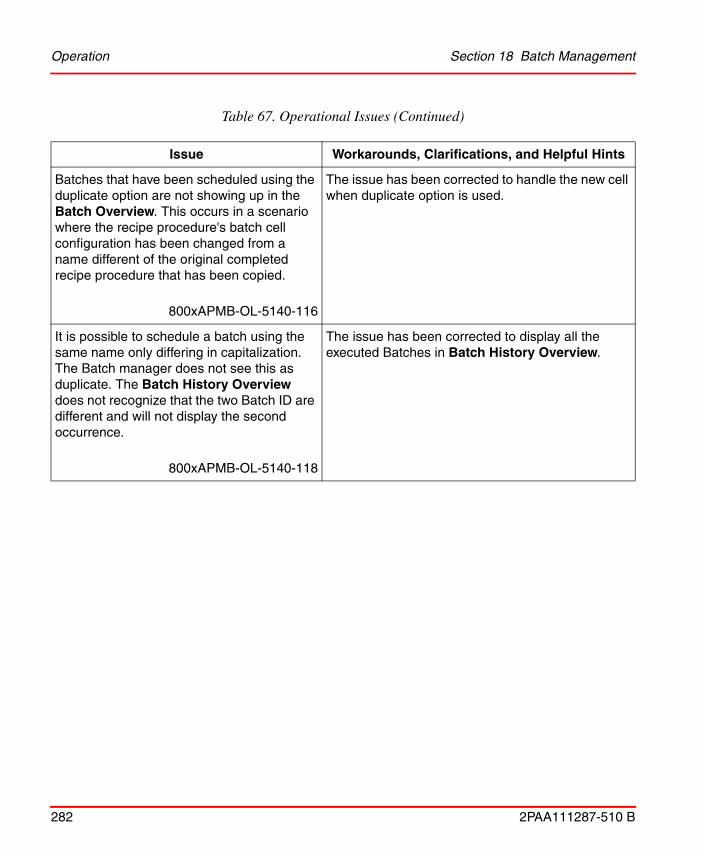
Operation Section 18 Batch Management
282 2PAA111287-510 B
Batches that have been scheduled using the duplicate option are not showing up in the Batch Overview. This occurs in a scenario where the recipe procedure's batch cell configuration has been changed from a name different of the original completed recipe procedure that has been copied.
800xAPMB-OL-5140-116
The issue has been corrected to handle the new cell when duplicate option is used.
It is possible to schedule a batch using the same name only differing in capitalization. The Batch manager does not see this as duplicate. The Batch History Overview does not recognize that the two Batch ID are different and will not display the second occurrence.
800xAPMB-OL-5140-118
The issue has been corrected to display all the executed Batches in Batch History Overview.
Table 67. Operational Issues (Continued)
Issue Workarounds, Clarifications, and Helpful Hints
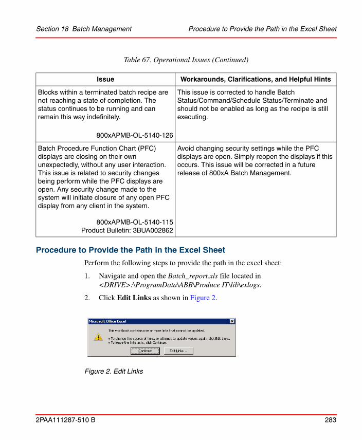
Section 18 Batch Management Procedure to Provide the Path in the Excel Sheet
2PAA111287-510 B 283
Procedure to Provide the Path in the Excel Sheet
Perform the following steps to provide the path in the excel sheet:
1. Navigate and open the Batch_report.xls file located in <DRIVE>:\ProgramData\ABB\Produce IT\lib\exlogs.
2. Click Edit Links as shown in Figure 2.
Blocks within a terminated batch recipe are not reaching a state of completion. The status continues to be running and can remain this way indefinitely.
800xAPMB-OL-5140-126
This issue is corrected to handle Batch Status/Command/Schedule Status/Terminate and should not be enabled as long as the recipe is still executing.
Batch Procedure Function Chart (PFC) displays are closing on their own unexpectedly, without any user interaction. This issue is related to security changes being perform while the PFC displays are open. Any security change made to the system will initiate closure of any open PFC display from any client in the system.
800xAPMB-OL-5140-115Product Bulletin: 3BUA002862
Avoid changing security settings while the PFC displays are open. Simply reopen the displays if this occurs. This issue will be corrected in a future release of 800xA Batch Management.
Figure 2. Edit Links
Table 67. Operational Issues (Continued)
Issue Workarounds, Clarifications, and Helpful Hints

Procedure to Provide the Path in the Excel Sheet Section 18 Batch Management
284 2PAA111287-510 B
3. The location encircled in Figure 3 is incorrect. The path has to be updated. Click Change Source.
4. Browse to the correct location of the file <DRIVE>:\Program Files (x86)\ABB Industrial IT\Produce IT\Batch\bin and then select Batch_fpexcel.xla file.
5. Click Check Status to check the status of the file link. Figure 4 shows the updated view of the Edit Links status displaying the Source is open.
6. Click Close. Save Batch_report.xls in the same location and close. If it prompts to save with a different file name, rename the file and save. Users will now be able to view and print the report.
Figure 3. Path to be Changed
Figure 4. Correct Path Selected

Section 18 Batch Management Instruction Manual Changes
2PAA111287-510 B 285
Instruction Manual Changes
Table 68 lists the issues that exist in the instruction manuals that have not been corrected since the previous version. Workarounds, clarifications, or helpful hints have been provided for each issue wherever possible.
Table 68. Instruction Manual Changes
Issue Workarounds, Clarifications, and Helpful Hints
System 800xA Batch Management - Configuration (3BUA000146*) instruction has incorrect path in the procedure to change the Batch OPC Group update rates in section Optimizing AC800M performance.
800xAPMB-MC-5104-004
The following information to be corrected in Section 2 (Optimizing AC800M performance).
Optimizing AC 800M Performance->Batch OPC Group Update Rates ->Step 2
Select the “HKEY_LOCAL_MACHINE on Local Machine” dialog:
• Windows 32-bit version, Navigate to
HKEY_LOCAL_MACHINE\SOFTWARE\ABB\Produce IT\5.1 \ Communications
• Windows 64-bit version, Navigate to
HKEY_LOCAL_MACHINE\ SOFTWARE \Wow6432Node\ ABB\Produce IT\5.1\Communications

Instruction Manual Changes Section 18 Batch Management
286 2PAA111287-510 B
System 800xA Batch Management - Configuration (3BUA000146*) instruction has incorrect references of SQL Server Enterprise Manager in section Optimizing RAM Usage.
800xAPMB-MC-5104-005
The following information to be corrected in Section 2 (Optimizing RAM Usage).
Configure the SQL Server software on Batch Management server workstations to limit the amount of RAM memory it will consume using the following procedure:
1. Use the SQL Server Management Studio to connect to the BATCH_INSTANCE.
2. Right-click BATCH_INSTANCE and then select Properties from the context menu.
3. Select the Memory Settings in the Server Properties dialog.
4. Change the Maximum Server Memory (in MB) field to be equal to 25 percent of the physical RAM of the Batch Server.
Table 68. Instruction Manual Changes
Issue Workarounds, Clarifications, and Helpful Hints

2PAA111287-510 B 287
Section 19 Information Management
Known ProblemsThis section details the Known Problems for Information Management that exist in the system at the time of release.
Installation
Table 69 lists issues that may exist and affect the installation and upgrade of the system or product at time of release. Workarounds, clarifications, or helpful hints have been provided for each issue wherever possible.
Table 69. Installation Issues
Issue Workarounds, Clarifications, and Helpful Hints
Issue is for 64-bit only
During installation of the Client Toolkit on 64-bit systems, the Client Toolkit prerequisite screen always shows the Microsoft Windows Service Pack as Not Found.
800xAINM-IN-5101-009
If the Windows Service Pack is installed, ignore this message and proceed. If the Windows Service Pack is not installed, install it first and then proceed.

Configuration Section 19 Information Management
288 2PAA111287-510 B
Configuration
Table 70 and Table 71 lists the issues that may exist and affect configuration of the system or product at time of release. Workarounds, clarifications, or helpful hints have been provided for each issue wherever possible.
Upgrading from Microsoft Office 2007 or Microsoft Office 2010 to higher supported versions before installing System 800xA Information Management Version 5.1 Revision D results in an installation error.
Important800xAINM-IN-5100-005
Upgrade to Microsoft Office 2010 or Microsoft Office 2013 after completing the upgrade to System 800xA Information Management Version 5.1 Revision D. After the Microsoft Office 2010 or Microsoft Office 2013 has been installed, it is necessary to manually load the DataDirect add-in. Refer to the DataDirect-Excel Data Access section in System 800xA Information Management Data Access and Reports (3BUF001094*) for instructions to load the DataDirect add-in.
Table 70. Configuration Issues
Issue Workarounds, Clarifications, and Helpful Hints
After update or upgrade of system, configuration of Action Aspect and Scheduling Definition aspect is set to default values on AO Asset Condition History and AO Running Time Report Job description objects.
Important800xAINM-CN-5100-003
Restore the Action Aspect and Scheduling Definition aspect configuration manually on the Asset Condition History and AO Running Time Report Job description object.
Table 69. Installation Issues (Continued)
Issue Workarounds, Clarifications, and Helpful Hints

Section 19 Information Management Operation
2PAA111287-510 B 289
Operation
Table 72, Table 74, Table 75, and Table 75 lists the issues that may exist and affect operation of the system or product at time of release. Workarounds, clarifications, or helpful hints have been provided for each issue wherever possible.
Data Direct XLA fails to load with the following error:
Microsoft Visual Basic
! Object library invalid or contains references to object definitions that could not be found.
Important800xAINM-CN-5103-036
Execute the following to remove old cached EXD files:
C:\ProgramData\ABB\IM\DataDirect\Bin\DeleteFilesAction.exe
This will find and delete all EXD files on the System Drive allowing the DataDirect XLA to load, the next time Excel is opened.
Table 71. Configuration Issues - History Services
Issue Workarounds, Clarifications, and Helpful Hints
It is difficult to recover an IM node when it is deleted from the system because objects under the node object are not deleted.
800xAINM-CN-3600-0004
Object under the node object needs to be deleted and recreated when the IM is added back into the system, including fixing the GUID for the PPA basic history. Contact ABB technical support for additional details.
When an Information Management server object is deleted from the Node Administration structure, the corresponding IM_Inform IT History_nodename, Service Provider object is not deleted from the Node Administration structure.
800xAINM-CN-3500-0004
Delete this object manually. It will be located at the top of the Node Administration Structure. Contact ABB technical support for additional details.
Table 70. Configuration Issues (Continued)
Issue Workarounds, Clarifications, and Helpful Hints

Operation Section 19 Information Management
290 2PAA111287-510 B
Table 72. Operational Issues - History Services
Issue Workarounds, Clarifications, and Helpful Hints
When using the Store Original Value feature of Information Management history logs type 5 (numeric), the original status is not stored when the value is modified.
Important800xAINM-OL-5020-018
History logs of type 1 should be used if the ability to save the original status when the status value is modified as desired.
Table 73. Operational Issues - Data Direct
Issue Workarounds, Clarifications, and Helpful Hints
The DataDirect menu is sometimes missing in Office 2013.
800xAINM-OL-5104-043
Follow the steps below to fix this issue. The procedure must be executed for each user that encounters this problem.
1. Open Excel.
2. Click the Add-ins tab.
3. Click the Options button of DataDirect to open Options window.
4. Go to View tab and change any of the options there and then click OK. The DataDirect menu will now be shown. The problem will not happen again for this user.

Section 19 Information Management Operation
2PAA111287-510 B 291
Table 74. Operational Issues - Application Scheduler
Issue Workarounds, Clarifications, and Helpful Hints
Scheduler Data Collection Actions will fail, with an error message Failed to Activate Log Number(s), if any of the logs in the Log List are from an AC400 controller and contain a period (".") in the log name.
Important800xAINM-OL-5104-041
No workaround exists for this issue.
A batch report scheduled to be run at the completion of a batch may miss data intended for the report.
Important800xAINM-OL-5020-043
If a batch report is intended to be automatically scheduled by the Batch Manager to include all data associated with a batch, include a delay block in the batch recipe just prior to the end of the recipe. The delay should include enough time (approximately 90 seconds) to ensure all data is available for reporting.
Reports executed manually will contain all data.
Excel may crash on exit after viewing a report that was launched from the File Viewer aspect. Dismiss the Excel error dialog to close Excel. This condition does not cause any data loss or corruption.
Important800xAINM-OL-5100-001
No workaround exists for this issue.

Operation Section 19 Information Management
292 2PAA111287-510 B
Scheduled reports may appear to fail when using the Save to History option. This shows the following error:
Job Action: Action Aspect, Completed (failure), Error while running automation type EX: Method'~' of object '~' failed
This error is occasionally seen only on reports that are configured by enabling the Save to History output option. The output file will still be correctly written to the history log in spite of the error message.
However, if the report is also configured to be exported to an 800xA Object (in addition to the “Save to History” output option), the report will not be written to the Completed Report Object when the error occurs.
Important800xAINM-OL-5100-002
If reports are configured to only store to History, then no action is required. The reports are still being stored properly.
If storing completed reports to History is not required, the issue can be avoided by clearing the selection of Save to History output option. In situations where both Save to History and Export to an Object Path options are necessary, reports may not be written properly to the Completed Report Object, but can be viewed through the History log.
Failed reports can also be rerun manually.
Table 74. Operational Issues - Application Scheduler (Continued)
Issue Workarounds, Clarifications, and Helpful Hints

Section 19 Information Management Operation
2PAA111287-510 B 293
Table 75. Operational Issues - Desktop Applications
Issue Workarounds, Clarifications, and Helpful Hints
Desktop tools may hang when run on a machine loaded with a 64-bit version of Windows and Internet Explorer 9.
This is not a problem on 32-bit versions of Windows or with other supported versions of Internet Explorer.
Important
800xAINM-OL-5104-040
To resolve this issue, perform the following procedure in all the user accounts that will run the Desktop Tools.
1. Open a File Explorer window and navigate to the folder, C:\Program Files (x86)\ABB Industrial IT\Inform IT\Desktop Trends\bin.
2. Double-click the file IE9_workaround.reg.
A message appears confirming if you trust the source of the file you are executing and asking if you want to continue.
4. Click Yes. A message appears The file has been placed in the Windows Registry.
5. Click OK to complete the installation.
The time offset feature of the desktop trend has been observed to cause the trace to disappear.
800xAINM-OL-5020-041
To obtain similar results, instead of using the time offset feature, modify the traces vertically by adjusting the range value of the Y axis.
Alarms and events from the Provider System (Multisystem Integration functionality) appear in the 800xA Alarm and Event List; however, only the alarms are recorded by DataDirect.
Important800xAINM-OL-5010-061
There is no workaround for this issue.

Instruction Manual Changes Section 19 Information Management
294 2PAA111287-510 B
Instruction Manual Changes
Table 76 lists the problems or issues in the instruction manuals that have been corrected since the previous version. A brief description of the correction has also been given wherever possible.
AID client (Display Services) displays sometimes use incorrect fonts. Due to a change in Windows functionality, AID client displays now uses font information from registry keys instead of the aidfonts.ini file.
800xAINM-OL-4100-0036
Add the HKEY_CURRENT_USER\ SOFTWARE\ABB\AID\Fonts\FaceName_0, ...\FaceName_1, and ...\FaceName_2 keys to the registry. Use the value names and values listed below for all three keys:
Value Name (Default) FontName ArialBaseSize_0 11BaseSize_1 14BaseSize_2 17BaseSize_3 18BaseSize_4 23BaseSize_5 33
Table 75. Operational Issues - Desktop Applications (Continued)
Issue Workarounds, Clarifications, and Helpful Hints

Section 19 Information Management Instruction Manual Changes
2PAA111287-510 B 295
Table 76. Instruction Manual Changes
Issue Workarounds, Clarifications, and Helpful Hints
The Testing Oracle Connections on page 247 of the System 800xA Maintenance (3BSE046784*) user manual mentions the password text to be entered. However, this password is set by the IM Oracle Instance wizard.
800xAINM-MC-5101-001
The following text on page 247:
SQLPLUS - log into history ADVA database:
user name = history, password = history
Change to:
SQLPLUS - log into history ADVA database:
user name = history, password = <password>
Information: The history password is set by the IM Oracle Instance wizard. Recall the password set when the Oracle DB was created to connect to Oracle as the history account.

Instruction Manual Changes Section 19 Information Management
296 2PAA111287-510 B

2PAA111287-510 B 297
Section 20 800xA for Advant Master
Known ProblemsThis section details the Known Problems for 800xA for Advant Master that exist in the system at the time of release.
Configuration
Table 77 lists the issues that may exist and affect the configuration of the system or product at time of release. Workarounds, clarifications, or helpful hints have been provided for each issue wherever possible.
Operation
Table 78 lists the issues that may exist and affect the operation of the system or product at time of release. Workarounds, clarifications, or helpful hints have been provided for each issue wherever possible.
Table 77. Configuration Issues
Issue Workarounds, Clarifications and Helpful Hints
The online help for On-line Builder Commands may not function for RTA board Configuration in Windows 7 and Windows Server 2008.
800xAADM-CN-5100-004
A Windows Help and Support window is displayed if any error occurs.
It is possible to correct the error by following the instructions provided in Microsoft Help and Support website. This instruction includes download of a program that helps to view the On-line Builder Commands help file.

Operation Section 20 800xA for Advant Master
298 2PAA111287-510 B
Table 78. Operational Issues
Issue Workarounds, Clarifications and Helpful Hints
Presentation of module position (field Pos) are wrong in the S800 IO Module Detailed View display, if S800 I/O clusters are used.
800xAADM-OL-5110-007
The problem can be manually corrected in the S800 IO Module Detail View graphic display as follows:
1) Go to the library AdvantMasterObjectTypesPG2Ext 1.0-n (where n is the revision of the library) Extension Library Version object, and open the Extension Library Version Definition aspect. Change the library state from Closed to Open.
2) Go to the S800 IO Modules object type object, and edit the S800 IO Module Detail View aspect.
3) Select the Pos value field (AdvantNumeric3 text) at the right of the text Pos.
4) Change expression for property Text (AdvantNumeric3 text) to
Format(“{0:#0}”, e_POS1 / 16 * 100 + e_POS1% 16)
5) Save and exit from the Process Graphics editor, and Close the library.
Problem occurs when adding a Redundant Connectivity Server.
After performing Add Redundant Server followed by the Configuration Wizard action Add RTA, the Event Collector Service provider for the newly created server does not enter the Service or Standby state.
800xAADM-OL-5110-008
Restart the Connectivity Server.
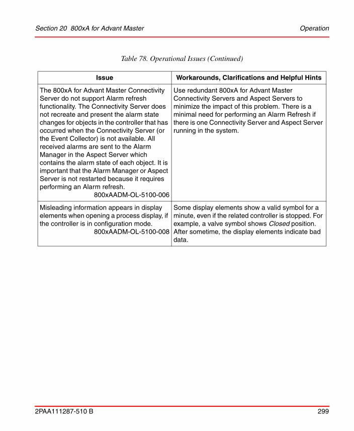
Section 20 800xA for Advant Master Operation
2PAA111287-510 B 299
The 800xA for Advant Master Connectivity Server do not support Alarm refresh functionality. The Connectivity Server does not recreate and present the alarm state changes for objects in the controller that has occurred when the Connectivity Server (or the Event Collector) is not available. All received alarms are sent to the Alarm Manager in the Aspect Server which contains the alarm state of each object. It is important that the Alarm Manager or Aspect Server is not restarted because it requires performing an Alarm refresh.
800xAADM-OL-5100-006
Use redundant 800xA for Advant Master Connectivity Servers and Aspect Servers to minimize the impact of this problem. There is a minimal need for performing an Alarm Refresh if there is one Connectivity Server and Aspect Server running in the system.
Misleading information appears in display elements when opening a process display, if the controller is in configuration mode.
800xAADM-OL-5100-008
Some display elements show a valid symbol for a minute, even if the related controller is stopped. For example, a valve symbol shows Closed position. After sometime, the display elements indicate bad data.
Table 78. Operational Issues (Continued)
Issue Workarounds, Clarifications and Helpful Hints

Operation Section 20 800xA for Advant Master
300 2PAA111287-510 B

2PAA111287-510 B 301
Section 21 800xA for Safeguard
Known ProblemsThis section details the Known Problems for 800xA for Safeguard that exist in the system at the time of release. It also enumerates known problems encountered in the final testing of this product release and identifies workarounds that help overcome the problem.
Operation
Table 79 lists the issues that may exist and affect operational of the system or product at time of release. Workarounds, clarifications, or helpful hints have been provided for each issue wherever possible.
Table 79. Operational Issues
Issue Workarounds, Clarifications and Helpful Hints
Double-click an Advant Master graphic element. This might display an Object Display instead of the Faceplate.
800xAADM-OL-4100-015
Execute the following steps:
1) Open the Aspect Precedence List aspect located in the Library Structure (Library Structure > Preferences & Customizations > Aspect Precedence Lists > Default precedence list).
2) Move the Default Aspect below the Faceplate.

Operation Section 21 800xA for Safeguard
302 2PAA111287-510 B
The aspect “AutroSafe ClassReason Translator for SG 400” updated to support SG1.6/4.
800xASAG-OL-5101-015
Safeguard 1.6/4 with option QC05-FIA12 requires installation or update of an event handling related aspect. This is distributed in import file “Safeguard400Translators.afw” that has to be installed. The file can be downloaded from ABB Library, or contact ABB Service Desk L3 support by e-mail to [email protected].
The 800xA for Advant Master and Safeguard Connectivity Server does not support Alarm refresh functionality. The Connectivity Server does not recreate and present the alarm state changes for objects in the controller that have occurred when the Connectivity Server (or the Event Collector) is not available.
800xASAG-OL-6000-001
800xA for Safeguard do not support Alarm refresh functionality for SG node objects. The Alarm refresh functionality is introduced in 800xA for Advant Master 5.0SP2 Rev. D.
Latest 800xA for Safeguard in SV5.1 is with 800xA for Advant Master 5.0SP2 Rev. B. Manual effort can be done on the SG Node Object Types to enable the function on those nodes as well.
Table 79. Operational Issues (Continued)
Issue Workarounds, Clarifications and Helpful Hints

2PAA111287-510 B 303
Section 22 800xA for AC 870P / Melody
There are no known problems in the current revision of System 800xA 5.1.

Section 22 800xA for AC 870P / Melody
304 2PAA111287-510 B

2PAA111287-510 B 305
Section 23 800xA for DCI
This section details the Known Problems for the 800xA for DCI that exist in the system at the time of release.
Installation
Table 80 lists issues that may exist and affect the installation and upgrade of the system or product at time of release. Workarounds, clarifications, or helpful hints have been provided for each issue wherever possible.
Table 80. Installation Issues
Issue Workarounds, Clarifications, and Helpful Hints
If the system is configured with 800xA Batch for DCI, and the System Update Tool is used to update to 800xA 5.1 current revision, in 800xA for DCI when DCI MSET objects are created or imported an error message appears due to an outdated aspect "MSET Type Definition.
The 40_DciBatchObjectTypes.afw file must be re-imported before uploading any DCI MSET objects.
800xADCI-IN-5101-002
Execute the following steps:
1. Open the Import/Export Tool from Start > All Programs > ABB Industrial IT 800xA > System > Import Export.
2. Click the Open icon or select File > Open, to open the 40_DciBatchObjectTypes.afw file.
Path for a 32-bit machine:
C:\ Program Files\ ABB Industrial IT\ 800xA\ DCI Library\ DciBatch\ import\ 40_DciBatchObjectTypes.afw
Path for a 64-bit machine:
C:\ Program Files (x86)\ ABB Industrial IT\800xA\ DCI Library\ DciBatch\ import\40_DciBatchObjectTypes.afw
3. Click the Import All icon or select Actions > Import All, and then click Finish.
Click Yes on the prompts on overwriting aspects.
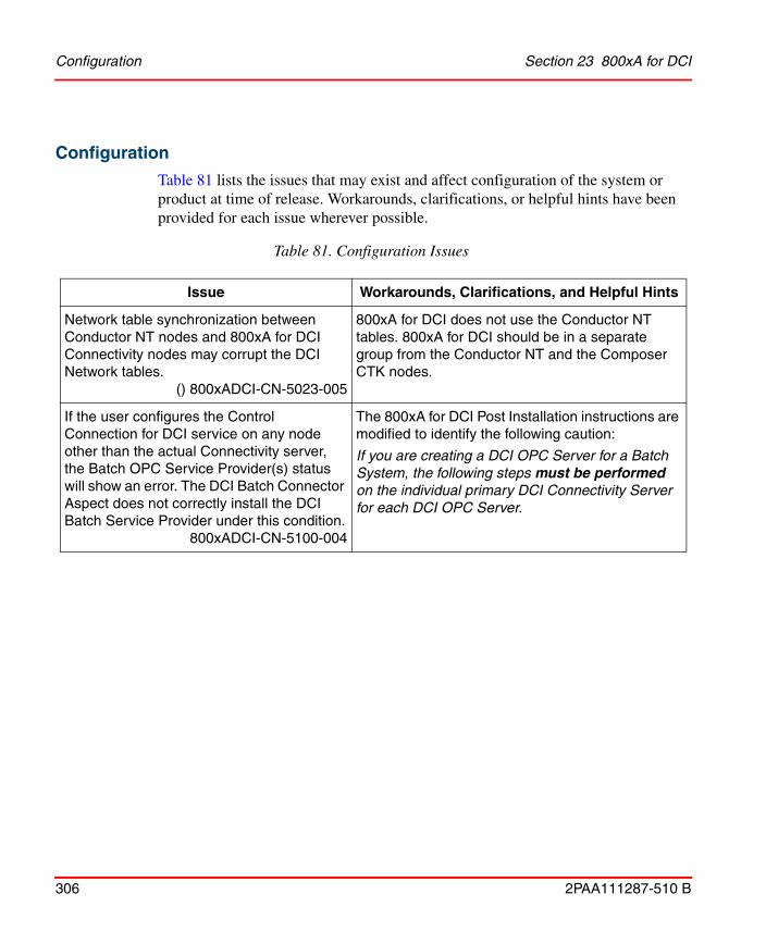
Configuration Section 23 800xA for DCI
306 2PAA111287-510 B
Configuration
Table 81 lists the issues that may exist and affect configuration of the system or product at time of release. Workarounds, clarifications, or helpful hints have been provided for each issue wherever possible.
Table 81. Configuration Issues
Issue Workarounds, Clarifications, and Helpful Hints
Network table synchronization between Conductor NT nodes and 800xA for DCI Connectivity nodes may corrupt the DCI Network tables.
() 800xADCI-CN-5023-005
800xA for DCI does not use the Conductor NT tables. 800xA for DCI should be in a separate group from the Conductor NT and the Composer CTK nodes.
If the user configures the Control Connection for DCI service on any node other than the actual Connectivity server, the Batch OPC Service Provider(s) status will show an error. The DCI Batch Connector Aspect does not correctly install the DCI Batch Service Provider under this condition.
800xADCI-CN-5100-004
The 800xA for DCI Post Installation instructions are modified to identify the following caution:
If you are creating a DCI OPC Server for a Batch System, the following steps must be performed on the individual primary DCI Connectivity Server for each DCI OPC Server.

Section 23 800xA for DCI Operation
2PAA111287-510 B 307
Operation
Table 82 lists the issues that may exist and affect operation of the system or product at time of release. Workarounds, clarifications, or helpful hints have been provided for each issue wherever possible.
Table 82. Operational Issues
Issue Workarounds, Clarifications, and Helpful Hints
800xA for DCI OPC DA Server may crash and automatically restart.
() 800xADCI-OL-5023-003
There is no workaround.
A redundant DCI Connectivity Server will take over when this crash occurs. Once the 800xA for DCI OPC DA server restarts, it will be ready to communicate with the DCI Network.
800xA for DCI System and Process alarms may not be acknowledgeable after an AE Server failover.
() 800xADCI-OL-5023-004
When the 800xA for DCI Alarm and Event (AE) Server fails over some or all of the existing Alarm and Event conditions can end up in a state where they cannot be acknowledged.
The problem has been traced to the method used to internally identify the alarms in the 800xA for DCI AE server.
Unacknowledged alarms may be removed.
On the Timer (TMR) Module faceplate, if the FMT Value is 11 the Stored Preset Limit (SPL) value cannot be written as HH:MM:SS.
800xADCI-OL-5022-008
The Stored Preset Limit (SPL) value can be entered in the SPL field of the Limits tab in the extended faceplate display in seconds only. This is identical to the entry from the Conductor NT TMR module Point Display [SP] button.

Operation Section 23 800xA for DCI
308 2PAA111287-510 B
A failover of an 800xA Batch for DCI Batch Server may not correctly identify when a phase is complete. When this happens, the phase continues to show as active on the Procedure Function Chart (PFC), even after the phase is complete. The recipe will not continue beyond the phase without manual intervention. This is of concern because there is no indication that the recipe has not continued.
800xADCI-OL-5101-007
Product Bulletin 3BUA002398
Refer to Workaround for Issue 800xADCI-OL-5101-007, page 311.
When the Module Set (MSET) Lock bit is set (LCK = 1), operators are not prevented from making changes to the module as was the case from Conductor NT.
800xADCI-OL-5101-008
Product Bulletin 3BUA002399
There are fundamental security differences when operating from Conductor NT and 800xA operator stations. DCI/Conductor NT security is server (DCU) based. 800xA security is client (operator station) based.
Workaround:
Configure the 800xA Control Connection permissions to disallow writes to any atom that a particular operator is not permitted to write to from a Conductor NT operator station when the module is locked.
That operator will not be able to write to those atoms from the 800xA operator station under any circumstance, but will still have the normal privileges at the Conductor NT operator station.
If those atoms need to be written from the 800xA operator station then they will need to be made by an operator permitted to write to them with the module locked or unlocked.
Table 82. Operational Issues (Continued)
Issue Workarounds, Clarifications, and Helpful Hints
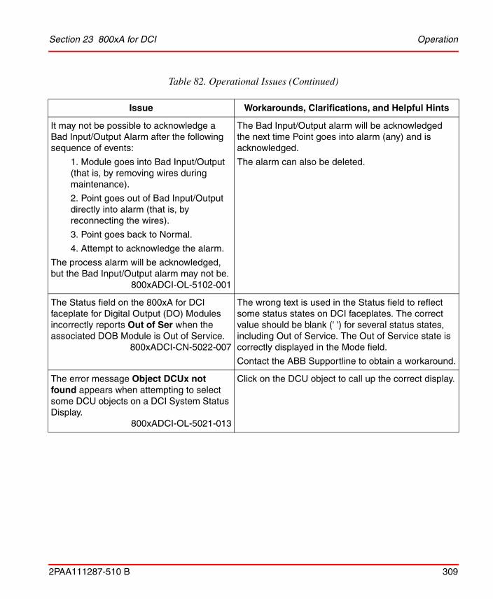
Section 23 800xA for DCI Operation
2PAA111287-510 B 309
It may not be possible to acknowledge a Bad Input/Output Alarm after the following sequence of events:
1. Module goes into Bad Input/Output (that is, by removing wires during maintenance).
2. Point goes out of Bad Input/Output directly into alarm (that is, by reconnecting the wires).
3. Point goes back to Normal.
4. Attempt to acknowledge the alarm.
The process alarm will be acknowledged, but the Bad Input/Output alarm may not be.
800xADCI-OL-5102-001
The Bad Input/Output alarm will be acknowledged the next time Point goes into alarm (any) and is acknowledged.
The alarm can also be deleted.
The Status field on the 800xA for DCI faceplate for Digital Output (DO) Modules incorrectly reports Out of Ser when the associated DOB Module is Out of Service.
800xADCI-CN-5022-007
The wrong text is used in the Status field to reflect some status states on DCI faceplates. The correct value should be blank (' ') for several status states, including Out of Service. The Out of Service state is correctly displayed in the Mode field.
Contact the ABB Supportline to obtain a workaround.
The error message Object DCUx not found appears when attempting to select some DCU objects on a DCI System Status Display.
800xADCI-OL-5021-013
Click on the DCU object to call up the correct display.
Table 82. Operational Issues (Continued)
Issue Workarounds, Clarifications, and Helpful Hints

Operation Section 23 800xA for DCI
310 2PAA111287-510 B
In certain installations, the following message may appear in the operator workplace:
A program running on this computer is trying to display a message.
When you click Show program details, it displays:
Message title: C:\ABB\bin\DualWatchdog.exe.
This pop-up does not indicate a problem, but this is an annoyance message.
800xADCI-OL-5101-004
The pop-up, if it appears, does not indicate a problem and can be ignored. If this pop-up regularly appears, it can be suppressed by making the following Windows configuration change, followed by a reboot:
Start > Control Panel > Administrative Tools > Services > ABB DCI Network Service > Properties > Log On tab
Clear the Allow service to interact with desktop checkbox.
For persons logged in as Application Engineer, the DCD module VB faceplate will not display information.
800xADCI-OL-5101-001
Follow one of the three workarounds below:
1. Use the DCD module PG2 faceplate, as it functions correctly.
2. Temporarily give the Application Engineer Operator rights to view the faceplate information.
3. Log into system as person with administrative rights to view the DCD module faceplate information.
PG2 Extended faceplate for DCD displays the ILB input as a real instead of boolean.
800xADCI-OL-5022-005
Note that ILB displays as 1.00 and 0.00, instead of the expected 1 and 0.
Table 82. Operational Issues (Continued)
Issue Workarounds, Clarifications, and Helpful Hints

Section 23 800xA for DCI Workaround for Issue 800xADCI-OL-5101-007
2PAA111287-510 B 311
Workaround for Issue 800xADCI-OL-5101-007
When a failover of an 800xA Batch for DCI Batch Server occurs and the secondary server takes control, you must:
• Determine if the issue has occurred.• If it has, recover from the issue.
To determine if the issue has occurred:
1. Review all active phase blocks by descending through the PFC runtime views until reaching one with a green phase block. This indicates an active phase. There can be more be more than one active phase block (in parallel paths) and you must wait for all of them to turn green.
Scheduled Batch fails with an error during DCI Connect Redundancy Switchover.
800xADCI-OL-5020-028
To tell if a phase is currently active, examine the MSEQ module (hierarchically directly under the MSET module). The faceplate provides the state of the current phase, if any. In addition, the CCL display will show where the phase is currently executing. If a Phase is selected, but the Run command has not been issued, the selected phase will show in yellow on the PHS line. When the phase is still running, the MSEQ faceplate will show this and the CCL display will show the executing statements.
If the Phase has been selected, but not run, restart the phase. If the phase is currently running, allow it to complete and then skip the phase. If no phase is selected, determine from the process if the phase has completed, and, if it has, skip the phase. Otherwise, restart the phase.
Disconnecting both control network cables from the primary DCI Connectivity Server does not force a switchover to the backup CS.
800xADCI-OL-5021-012
You must shut down the primary CS to force the switchover.
Table 82. Operational Issues (Continued)
Issue Workarounds, Clarifications, and Helpful Hints

Workaround for Issue 800xADCI-OL-5101-007 Section 23 800xA for DCI
312 2PAA111287-510 B
2. Right-click the phase block and select Faceplate to show the reduced faceplate of the Mini-Sequence (MSEQ) module that is running the phase.
3. Click the button with two diamonds at the bottom of the faceplate to show the normal faceplate view.
4. If the block next to PHS shows a (0), and the block next to the Batch Unit Mode shows Auto, then the phase has already completed.
To recover from the issue, clear the phase. To clear the phase:
1. Return to the PFC, right-click on the phase block, and select Status from the context menu.
2. In the Overviews : Block Status dialog box:
a. Click the drop-down box arrow next to the State block at the bottom of the Block Status dialog box.
b. Select Abort from the list.
c. Click Apply.
3. Once again, click the drop-down box arrow next to the State block at the bottom of the Block Status dialog box.
4. Select Continue at Next.
5. Click Apply.
6. Dismiss the Block Status dialog box and the MSEQ faceplate.
Even if the phase is currently running, there is still a potential for missing the phase completion if the phase was active during the failover. You need to monitor the phase until it completes.
You must do this for every active phase unless you know for certain that the phase was not active during the switchover.

2PAA111287-510 B 313
Section 24 800xA for Harmony
Known ProblemsThis section details the Known Problems for the 800xA for Harmony that exist in the system at the time of release.
Installation
Table 83 lists the issues that may exist and affect installation of the system or product at time of release. Workarounds, clarifications, or helpful hints have been provided for each issue wherever possible.
Table 83. Installation Issues
Issue Workarounds, Clarifications, and Helpful Hints
Issue is for 64-bit only
800xA for Harmony does not support SCSI INICI03 or later interfaces on 64-bit Windows 2008 R2 SP1.
800xAHAR-IN-5101-004
800xA for Harmony supports SCSI INICI03 or later interfaces on 32-bit Windows 2008 SP2. 800xA for Harmony supports IET800 on 32-bit Windows 2008 SP2 and 64-bit Windows 2008 R2 SP1.
When updating from 800xA for Harmony 5.1 to 800xA for Harmony 5.1 Rev B, a pop-up might appear for COM surrogate and IIS process.
800xAHAR-IN-5102-001
Click Retry to uninstall 800xA for Harmony 5.1 and continue.
On the first reboot after an SUT Installation, 800xA for Harmony tags may not be able to load.
800xAHAR-IN-5102-002
From the 800xA Plant Explorer in the Service Structure, Disable and then Enable the Harmony Executive Service on the machine displaying this dialog to correct the problem. It is recommended to wait 5 minutes before performing this operation.

Administration Section 24 800xA for Harmony
314 2PAA111287-510 B
Administration
Table 84 lists the issues that may exist and affect administration of the system or product at time of release. Workarounds, clarifications, or helpful hints have been provided for each issue wherever possible.
Configuration
Table 85 lists the issues that may exist and affect configuration of the system or product at time of release. Workarounds, clarifications, or helpful hints have been provided for each issue wherever possible.
Table 84. Administration Issues
Issue Workarounds, Clarifications, and Helpful Hints
Cannot set the IP address of the IET800 when working in a virtual environment.
800xAHAR-AD-5101-001
Use a hyper terminal connected to the serial port of the IET800 to set the IP address. IET800 diagnostic mode must be enabled.
Table 85. Configuration Issues
Issue Workarounds, Clarifications, and Helpful Hints
The VB Graphics Migration Tool will not show migrated aspects for the 800xA for Harmony INFI 90 Harmony Analog Read and INFI 90 Harmony Station Read object types. Internal data within the reduced faceplate element for Analog Reads and the point display element for Stations cause this issue.
800xAHAR-CN-5100-008
To workaround this issue:
1. Move the reduced faceplate element for Analog Reads and the point display element for Stations to someplace else in the Object Type Structure.
2. Migrate the Harmony Analog Read and Harmony Station Read object types.
3. After completing the migration, move the elements in Step 1 back to their original locations.
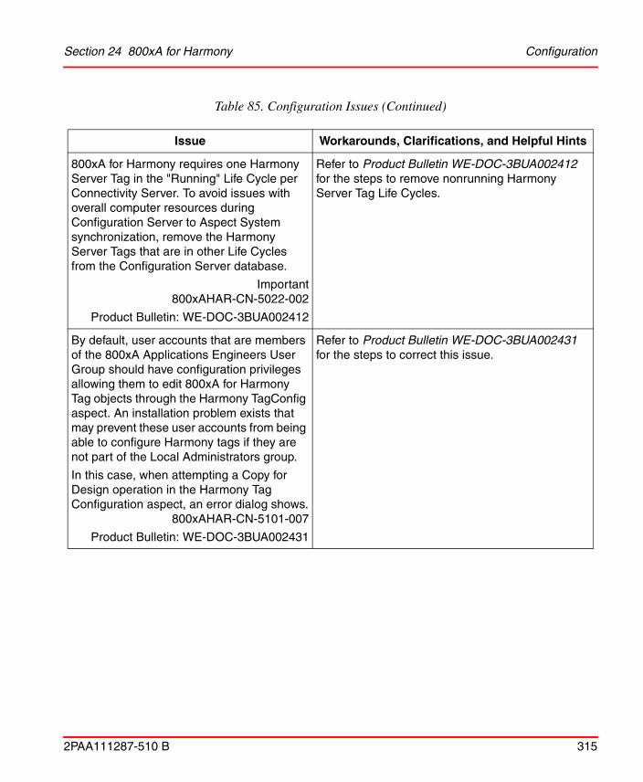
Section 24 800xA for Harmony Configuration
2PAA111287-510 B 315
800xA for Harmony requires one Harmony Server Tag in the "Running" Life Cycle per Connectivity Server. To avoid issues with overall computer resources during Configuration Server to Aspect System synchronization, remove the Harmony Server Tags that are in other Life Cycles from the Configuration Server database.
Important800xAHAR-CN-5022-002
Product Bulletin: WE-DOC-3BUA002412
Refer to Product Bulletin WE-DOC-3BUA002412 for the steps to remove nonrunning Harmony Server Tag Life Cycles.
By default, user accounts that are members of the 800xA Applications Engineers User Group should have configuration privileges allowing them to edit 800xA for Harmony Tag objects through the Harmony TagConfig aspect. An installation problem exists that may prevent these user accounts from being able to configure Harmony tags if they are not part of the Local Administrators group.
In this case, when attempting a Copy for Design operation in the Harmony Tag Configuration aspect, an error dialog shows.
800xAHAR-CN-5101-007
Product Bulletin: WE-DOC-3BUA002431
Refer to Product Bulletin WE-DOC-3BUA002431 for the steps to correct this issue.
Table 85. Configuration Issues (Continued)
Issue Workarounds, Clarifications, and Helpful Hints

Operation Section 24 800xA for Harmony
316 2PAA111287-510 B
Operation
Table 86 lists the issues that may exist and affect operation of the system or product at time of release. Workarounds, clarifications, or helpful hints have been provided for each issue wherever possible.
When exporting/importing PG2 graphic displays from one Harmony system to the other, there is no Display Tool available to fix object references.
800xAHAR-CN-5021-006
To transfer PG2 aspects and resolve and approve them on a different system:
• Import the PG2 graphic displays.
- Aspect by aspect - Data References > Resolve All > OK > Save, Close.
- Partial Multiple aspects - Use the Check Consistency Tool > Select All > Repair > All aspects will be Unapproved. Drag each object/aspect into the Reference Tool > Approve.
Table 86. Operational Issues
Issue Workarounds, Clarifications, and Helpful Hints
The Harmony Synchronizer fails to complete if any objects are added to the INFI 90 Harmony Object Type Group in the Object Type Structure or if copies of existing INFI 90 Harmony Tag Object Types are made under the INFI 90 Harmony Object Type Group.
800xAHAR-OL-5020-008
Remove all the newly created or copied objects and object types under the INFI 90 Harmony Object Type Group and re-synchronize.
Table 85. Configuration Issues (Continued)
Issue Workarounds, Clarifications, and Helpful Hints
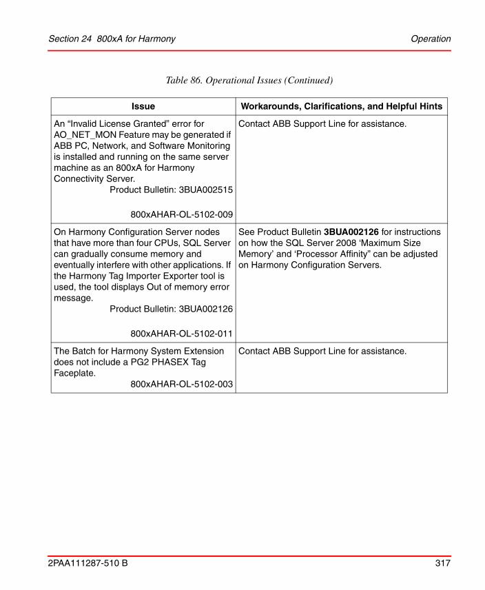
Section 24 800xA for Harmony Operation
2PAA111287-510 B 317
An “Invalid License Granted” error for AO_NET_MON Feature may be generated if ABB PC, Network, and Software Monitoring is installed and running on the same server machine as an 800xA for Harmony Connectivity Server.
Product Bulletin: 3BUA002515
800xAHAR-OL-5102-009
Contact ABB Support Line for assistance.
On Harmony Configuration Server nodes that have more than four CPUs, SQL Server can gradually consume memory and eventually interfere with other applications. If the Harmony Tag Importer Exporter tool is used, the tool displays Out of memory error message.
Product Bulletin: 3BUA002126
800xAHAR-OL-5102-011
See Product Bulletin 3BUA002126 for instructions on how the SQL Server 2008 ‘Maximum Size Memory’ and ‘Processor Affinity” can be adjusted on Harmony Configuration Servers.
The Batch for Harmony System Extension does not include a PG2 PHASEX Tag Faceplate.
800xAHAR-OL-5102-003
Contact ABB Support Line for assistance.
Table 86. Operational Issues (Continued)
Issue Workarounds, Clarifications, and Helpful Hints

Operation Section 24 800xA for Harmony
318 2PAA111287-510 B
800xA for Harmony Connectivity Server stability issues have been observed during on-line tag configuration change processing.
Symptoms reported include Harmony Servers reporting Internal Error Status, Harmony Tag values not updating, invalid data events being generated by Harmony Servers, and Harmony Servers failing back and forth.
800xAHAR-OL-5022-003Product Bulletin: 3BUA002660
It is recommended that users disable 800xA for Harmony online change processing to avoid the potential 800xA for Harmony Connectivity Server performance and stability issues.
To disable online change processing:
• Disable the synchronization data after each object update option in the Management Tab of the Harmony System Definition Object. Note that the Harmony Servers must be restarted to enable this configuration change.
• When using the Tag Importer utility to import tags, select the Manual Restart option.
800xA for Harmony may incorrectly report a resource shortage for Nonpaged Pool Memory. If this problem occurs:
• The Harmony Server Tag will show an “Internal Error” status for the Harmony Server Tag Object,
• A “Low Resource” alarm will be generated. The issue is a result of the default Nonpaged Pool Memory alarm value limits being set too low.
800xAHAR-OL-5101-008
Contact ABB Support Line for assistance with updating the default Nonpaged Pool Memory alarm value limits.
Block and Module Detail display call-up times can be between 5 and 30 seconds when using an IET800 with 800xA for Harmony.
800xAHAR-OL-5101-003
There is no workaround. The call-up time for the Block and Module Detail display does not impact normal plant operation and control.
Table 86. Operational Issues (Continued)
Issue Workarounds, Clarifications, and Helpful Hints

2PAA111287-510 B 319
Section 25 800xA for MOD 300
Known ProblemsThis section details the Known Problems for the 800xA for MOD 300 that exist in the system at the time of release.
Installation
Table 87 lists issues that may exist and affect the installation and upgrade of the system or product at time of release. Workarounds, clarifications, or helpful hints have been provided for each issue wherever possible.
Configuration
Table 88 lists the issues that may exist and affect configuration of the system or product at time of release. Workarounds, clarifications, or helpful hints have been provided for each issue wherever possible.
Table 87. Installation Issues
Issue Workarounds, Clarifications, and Helpful Hints
There is a problem with the 800xA for MOD 300 Client.vs. Client/Server installation package of 800xA for MOD 300.
800xAMOD-IN-5024-002
Do not select the Client/Connectivity Server option if installing on a client node. This will install server components that are not required.

Operation Section 25 800xA for MOD 300
320 2PAA111287-510 B
Operation
Table 89 lists the issues that may exist and affect operation of the system or product at time of release. Workarounds, clarifications, or helpful hints have been provided for each issue wherever possible.
Table 88. Configuration Issues
Issue Workarounds, Clarifications, and Helpful Hints
Users are unable to select from the drop down menus (for example, Group Status, Area Status), while using certain multiple monitor configurations.
The problem occurs when multiple monitors are used in a "stacked" configuration and the primary monitor is not configured as one of the monitors on the bottom.
Multiple monitors used in a side by side configuration are not experiencing this problem. There is no problem with single monitor configuration.
800xAMOD-CN-5020-018
Users should avoid the configuration as stated in the issue description.
Whenever you use an attribute for a loop that contains a PID FCM, both Medic and 800xA show the .PID extension. If the loop does not contain a PID FCM, it shows only the loop name without the LCM extension. This is also observed with the GET FCM. It appears that addressing any attribute with the LCM extension changes to .PID when the loop in which you are getting the attribute from contains a PID FCM.
800xAMOD-CN-5020-021
This is a display issue and does not affect operation.

Section 25 800xA for MOD 300 Operation
2PAA111287-510 B 321
Table 89. Operational Issues
Issue Workarounds, Clarifications, and Helpful Hints
MOD 300 Diagnostic Message do not synchronize across multiple 800xA for MOD 300 Alarm and Event server pairs (For example: When the AE Servers are in their own unique AE Service Group).
800xAMOD-OL-5011-011
There is no workaround for this issue.
When the same Diagnostic Message is received by MOD 300 Alarm and Event Servers configured in separate Service Groups, the alarm may not be acknowledged.
PDL messages originating from the TCL, such as those generated by the STARTBATCH, ENDBATCH, and RECORD statements, are not stored in the PDL database when they contain fields with any of the following characters: <. >, ', “, &.
800xAMOD-OL-5023-006
Do not use the characters <. >, ', “, & in TCL messages.
MOD 300 Display Servers can stop responding due to a number of scenarios, resulting in blue status dots on MOD 300 displays.
800xAMOD-OL-5101-006
Product Bulletin 3BUA002386
Use the Processes tab in Windows Task Manager to manually terminate The Display Server on the 800xA for MOD 300 Connectivity Server where the blue dot indicates the server has stopped responding.
The MOD 300 Display Servers affected by this issue are:
• AdvDiagServer.exe
• AdvHSServer.exe
• AdvIOServer.exe
• AdvLoopServer.exe
• AdvRDPEmulatorServer.exe
• AdvTclServer.exe
• AdvTllServer.exe
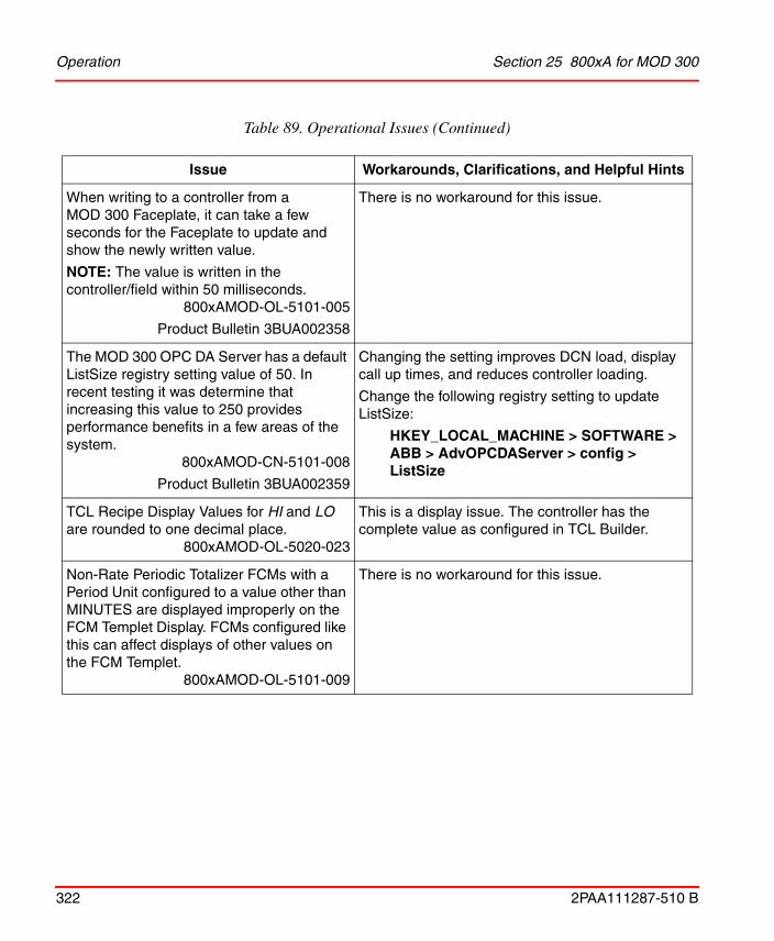
Operation Section 25 800xA for MOD 300
322 2PAA111287-510 B
When writing to a controller from a MOD 300 Faceplate, it can take a few seconds for the Faceplate to update and show the newly written value.
NOTE: The value is written in the controller/field within 50 milliseconds.
800xAMOD-OL-5101-005
Product Bulletin 3BUA002358
There is no workaround for this issue.
The MOD 300 OPC DA Server has a default ListSize registry setting value of 50. In recent testing it was determine that increasing this value to 250 provides performance benefits in a few areas of the system.
800xAMOD-CN-5101-008
Product Bulletin 3BUA002359
Changing the setting improves DCN load, display call up times, and reduces controller loading.
Change the following registry setting to update ListSize:
HKEY_LOCAL_MACHINE > SOFTWARE > ABB > AdvOPCDAServer > config > ListSize
TCL Recipe Display Values for HI and LO are rounded to one decimal place.
800xAMOD-OL-5020-023
This is a display issue. The controller has the complete value as configured in TCL Builder.
Non-Rate Periodic Totalizer FCMs with a Period Unit configured to a value other than MINUTES are displayed improperly on the FCM Templet Display. FCMs configured like this can affect displays of other values on the FCM Templet.
800xAMOD-OL-5101-009
There is no workaround for this issue.
Table 89. Operational Issues (Continued)
Issue Workarounds, Clarifications, and Helpful Hints

Section 25 800xA for MOD 300 Operation
2PAA111287-510 B 323
When using S100 I/O, LKP FCM dDisplay Compensation Types are incorrect in 800xA for MOD 300.
800xAMOD-OL-5101-010
This is a display issue. The correct Compensation is displayed in AdvaBuild.
Messages appear to be lost from TCL programs.
If a duplicate Billboard message is generated, this message will appear at the bottom of the list. This message also shows the original active time, giving the appearance that the message is lost
800xAMOD-OL-5010-027
This problem can occur if there is a message queue of 256 messages. If the messages are not acknowledged in a timely manner, the recurring Billboard message can appear to be lost because it appears at the bottom of the list.
If Billboard messages are acknowledged in a timely manner, this problem will not occur. The workaround for these messages is to create an Event List for the Billboard messages and sort them by 'Event Time' rather than the default 'Active Time'.
Table 89. Operational Issues (Continued)
Issue Workarounds, Clarifications, and Helpful Hints

Operation Section 25 800xA for MOD 300
324 2PAA111287-510 B

2PAA111287-510 B 325
Section 26 800xA for TRIO
Known ProblemsThis section details the Known Problems for 800xA for TRIO that exist in the system at the time of release. It also enumerates known problems encountered in the final testing of this product release and identifies workarounds that help overcome the problem.
Installation
Table 90 lists issues that may exist and affect the installation and upgrade of the system or product at time of release. Workarounds, clarifications, or helpful hints have been provided for each issue wherever possible.
Table 90. Installation Issues
Issue Workarounds, Clarifications, and Helpful Hints
A firmware upgrade of the CI862 through the Control Builder may fail. If you click Show Firmware Information, it will show the BOOT version for the failed module and the fault LED will keep blinking on the respective CI862 module.
800xATRI-IN-5010-001
Download the firmware to the respective module. When the file transfer window shows 10 seconds, perform a hot swap of the module and then retry. The firmware will be upgraded and the Version column will show the correct downloaded version.

Configuration Section 26 800xA for TRIO
326 2PAA111287-510 B
Configuration
Table 91 lists the issues that may exist and affect configuration of the system or product at time of release. Workarounds, clarifications, or helpful hints have been provided for each issue wherever possible.
Online upgrade is not supported on a controller with CI862 installed.
800xATRI-IN-5010-002
Only a hot swap of a CI862 interface is supported.
Sometimes, during the firmware upgrade of a CI862 in the lower segment (positions 7-12) of the redundant controller, it may fail.
800xATRI-IN-5012-001
Upgrade the firmware again. If this does not work, upgrade the firmware of the CI862 modules only on the upper CEX segment (positions 1-6). Then swap the upper CI862 segment with the lower one. Now upgrade the new upper CI862 segment.
Table 91. Configuration Issues
Issue Workarounds, Clarifications, and Helpful Hints
Baud rate change in CB on CI862 does not affect communication with TRIO IO modules. User will observe this scenario when Baud Rate of TRIO blocks are changed while configuration is present in the controller.
800xATRI-CN-5101-001
User should Reset the controller and download the application to CB. Then correct behavior can be seen. Do not perform baud rate changes on TRIO IO modules in running plant.
If the CI862 is deleted in the hardware tree of the Control Builder application and program is downloaded, the Controller may crash.
Important
800xATRI-CN-5101-002
Reset the controller if a CI862 is removed from the hardware tree in Control Builder M. Do not delete CI862 modules configured in CB in running plant.
Table 90. Installation Issues (Continued)
Issue Workarounds, Clarifications, and Helpful Hints

Section 26 800xA for TRIO Configuration
2PAA111287-510 B 327
IPConfig throws error when PM864 connected with CI862.
800xATRI-CN-5101-003
Set the IP of the controller first using IPCONFIG before connecting the CI862 on the CEX bus.
Problem observed when hot swap of multiple CI862 modules is performed.
For example, four CI862 modules at positions 1,3,7 and 9 exist. The CI862 at position 3 is removed and reinserted.
Before the CI862 at position 3 comes up, CI862 at position 1 is removed and reinserted. After re-insertion, the CI862 at position 1 goes into fault and does not come up.
The controller log shows the following:
Update driver instance Single 1[new:17 old:12] for Index: 1
Single CEM at pos 1 is reset by GIOC Framework[Stat: 0x00000400]
a Hot removal, Hot insert message
Update driver instance Single 1[new:18 old:17] for Index: 1
Important
800xATRI-CN-4000-0002
Insert only one CI862 at a time, wait until it is up and running before inserting the next CI862.
Table 91. Configuration Issues (Continued)
Issue Workarounds, Clarifications, and Helpful Hints

Configuration Section 26 800xA for TRIO
328 2PAA111287-510 B
The user changes the default setting of IN_16CKT for “open wire detection”, “Report fault” and “Short circuit detection” to “False”. After downloading the application to the controller, a Config Error message is shown in the unit status tab of the I/O module.
800xATRI-CN-5012-002
Perform a power reset of the I/O module to remove this message.
CI862 module goes to fault state when a baud rate of 38.4 KB is configured and downloaded from Control Builder.
800xATRI-CN-5020-001
The CI862 does not support baud rate of 38.4 KB.
Signal range settings are lost for the 4IN2OUT block when an earlier version of a Control Builder project is upgraded.
800xATRI-CN-5020-002
Hardware settings for the 4IN2OUT block has changed. Signal Range Channel 1- 4 has been split up in the following two new settings:
Channel High Range and Low Range.
For IO_32CKT block, channel type can only be configured as either input or output.
Important
800xATRI-CN-5020-003
The IO_32CKT block does not support Open Wire diagnostics. Due to this the Tri-State option is not available for the parameter setting "Channel type" for this block.
Repeated re-configuration related to changing the position of CI862 with warm restart may lead to Controller crash.
Important
800xATRI-CN-5020-006
Perform a cold restart of controller after every reconfiguration related to position of CI862 module. Do not perform repeated re-configuration related to CI862 in a running plant.
Table 91. Configuration Issues (Continued)
Issue Workarounds, Clarifications, and Helpful Hints

Section 26 800xA for TRIO Configuration
2PAA111287-510 B 329
User removes both the CI862 in a redundant configuration by removing Primary first and then the other CI862. Configure Non-Redundant Configuration and download it to the controller without any CI862 at the configured position. CI862 does not start and does not communicate.
800xATRI-CN-5020-007
User should make sure that CI862 is inserted at the configured position before downloading.
Table 91. Configuration Issues (Continued)
Issue Workarounds, Clarifications, and Helpful Hints

Operation Section 26 800xA for TRIO
330 2PAA111287-510 B
Operation
Table 92 lists the issues that may exist and affect operations of the system or product at time of release. Workarounds, clarifications, or helpful hints have been provided for each issue wherever possible.
Table 92. Operational Issues
Issue Workarounds, Clarifications, and Helpful Hints
When the CI862 modules are connected with CEX bus extender module BC810 and power reset is done to the controller, the CI862 modules do not come up after power reset.
Important
800xATRI-OL-5101-002
Reset the controller or conduct hotswap of CI862.
Module remains online even when block ID is changed using HHM. User will observe this scenario when position of TRIO blocks are changed while configuration is present in the controller.
Important
800xATRI-OL-5101-003
User should Reset the controller and download the application to CB. Then the error will be displayed correctly. The Block ID should not be changed in running plant.
User will observe communication problem during switchover in sequence because LAN redundancy is controlled by BSM (Bus Switching Module). Whenever a LAN is removed, BSM switches to the other LAN without seeing its status.
Important
800xATRI-OL-5101-004
User should make sure that Active LAN (indicated by Red LED present on BSM) is connected to CI862 module. The OSP setting for output modules should be set to Hold last value to prevent any disturbance in process during the switch over.

Section 26 800xA for TRIO Operation
2PAA111287-510 B 331
“PRIM” status LED OFF on both the CI862 modules in a redundant CI862 configuration. User will observe this scenario when Baud Rate of TRIO blocks are changed while configuration is present in the controller.
Important
800xATRI-OL-5101-005
User should Reset the controller and download the application to CB. Then correct behavior can be seen. Baud rate of CI862 modules should not be done in running plant.
CI862 module goes to fault after power reset of controller.
Important
800xATRI-OL-5101-006
1. Remove TRIO LAN communication cable.
2. Hot swap of the CI862 module.—CI862 module comes up to Run state.
3. Connecting back the LAN communication cable.
Outputs go to OSP value during CI862 LAN switchover for a about 100 ms.
Important
800xATRI-OL-5101-007
The OSP setting shall be made hold last value to prevent any disturbance in process during the switch over.
If the user removes both CI862 module (or both become faulty) in a redundant CI862 configuration system, the TRIO blocks go to OSP values or holds to the last good value. In Control Builder, the last good value is shown. If one of the CI862 is replaced with a working CI862, the moment the TRIO blocks start communicating with the new CI862, for a short period, the input value goes to zero or the highest value in Control Builder.
800xATRI-OL-5012-004
Use filter in application logic to prevent disturbance in process.
Table 92. Operational Issues (Continued)
Issue Workarounds, Clarifications, and Helpful Hints

Operation Section 26 800xA for TRIO
332 2PAA111287-510 B
In a redundant CI862 system, if LAN A goes faulty (or CEX module), the communication switches to LAN B. If LAN B also fails, the BSM status shows that the communication switched back to LAN A. Since LAN A is not connected, all modules in that LAN goes to a Block failed status. If the user replaces LAN B (or CEX module) first, communication does not start on LAN B. The BSM still shows that LAN A is the active LAN.
Important
800xATRI-OL-5012-005
Monitor the BSM LED to identify where exactly the TRIO blocks are looking for communication.The LED in the BSM tells exactly where the blocks are looking for communication (if the LED is turned ON, the blocks are looking for communication in LAN B, else LAN A). Based on this information, plug in the new CEX module (or LAN) in the respective CEX position in online mode for all the modules in that LAN. Communication will resume.
If any I/O value of a TRIO block is forced using HHM, there is no specific indication in Control Builder that a value has been forced in that block.
800xATRI-OL-5012-006
"HHM in Use" message will appear in Control Builder in online mode for all the TRIO modules in that LAN. PPA will show an event stating “Block n config changed by HHM” letting the user know something has changed.
In a redundant controller and redundant CI862 configuration, if LAN A goes faulty (or CEX module) the communication switches to LAN B. Communication with I/O modules is working properly. However, the CI862 module does not switch over. In this case, if the TRL cable between the primary and secondary CI862 modules becomes faulty, communication of the I/O modules in the LAN stops.
800xATRI-OL-5012-007
TRIO does not support double fault (when the redundant CEX module is also failed). In Control Builder, a warning appears as soon as the TRL cable is disconnected or broken. After this, replace the faulty TRL with a working
one.
Table 92. Operational Issues (Continued)
Issue Workarounds, Clarifications, and Helpful Hints

Section 26 800xA for TRIO Operation
2PAA111287-510 B 333
When Blocks are communicating to LAN A, and if LAN A goes faulty no information to operator.
800xATRI-OL-5020-001
The operator shall be notified with the event <Blocks have switched to LAN B, Check LAN A>. But if the other LAN (that is, in this case LAN B), through which Blocks are not communicating is removed/Faulty, no information is provided to Operator.
When Blocks are communicating to LAN B, and if LAN B goes faulty, no information is shown to operator.
800xATRI-OL-5020-002
The operator shall be notified with the event <Blocks have switched to LAN A, Check LAN B>. But if the other LAN (i.e. in this case LAN A), through which Blocks are not communicating is removed/Faulty No information is provided to Operator.
After initial download, Latched Extended Status shows the message “Block Failed” for all the blocks.
800xATRI-OL-5020-003
After initial download, either acknowledge latched extended status or issue the “Command 19” with the “Command Channel” for the concerned blocks.
The following messages may be received in the PPA:
“Blocks have switched to LAN B, Check LAN A”.
“Blocks have switched to LAN A Check LAN B”.
TRIO has detected the LAN switch.
800xATRI-OL-5020-004
When the LAN through which blocks communicates goes faulty/removed, blocks switch to the other LAN and user would be notified about the same through these events. Check the LAN connections and terminations.
Table 92. Operational Issues (Continued)
Issue Workarounds, Clarifications, and Helpful Hints
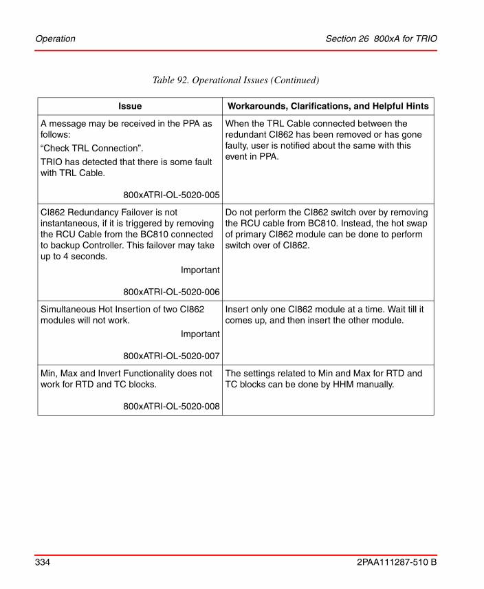
Operation Section 26 800xA for TRIO
334 2PAA111287-510 B
A message may be received in the PPA as follows:
“Check TRL Connection”.
TRIO has detected that there is some fault with TRL Cable.
800xATRI-OL-5020-005
When the TRL Cable connected between the redundant CI862 has been removed or has gone faulty, user is notified about the same with this event in PPA.
CI862 Redundancy Failover is not instantaneous, if it is triggered by removing the RCU Cable from the BC810 connected to backup Controller. This failover may take up to 4 seconds.
Important
800xATRI-OL-5020-006
Do not perform the CI862 switch over by removing the RCU cable from BC810. Instead, the hot swap of primary CI862 module can be done to perform switch over of CI862.
Simultaneous Hot Insertion of two CI862 modules will not work.
Important
800xATRI-OL-5020-007
Insert only one CI862 module at a time. Wait till it comes up, and then insert the other module.
Min, Max and Invert Functionality does not work for RTD and TC blocks.
800xATRI-OL-5020-008
The settings related to Min and Max for RTD and TC blocks can be done by HHM manually.
Table 92. Operational Issues (Continued)
Issue Workarounds, Clarifications, and Helpful Hints

Section 26 800xA for TRIO Miscellaneous
2PAA111287-510 B 335
Miscellaneous
Table 93 list the problems or issues known to exist with the current release that do not fit into one of the other categories. A workaround, when possible, has been identified for each problem or issue.
Table 93. Miscellaneous Issues
Issue Workarounds, Clarifications, and Helpful Hints
Online Help files are not available for TRIO.
800xATRI-MS-5010-005
For more information, refer to 800xA for TRIO/Genius Getting Started (3BUR002459*) and 800xA for TRIO/Genius (3BUR002460*).

Miscellaneous Section 26 800xA for TRIO
336 2PAA111287-510 B

2PAA111287-510 B 337
Section 27 Snapshot Reports for 800xA
There are no known problems in the current revision of System 800xA 5.1.

Section 27 Snapshot Reports for 800xA
338 2PAA111287-510 B

2PAA111287-510 B 339
Revision History
This section provides information on the revision history of these Release Notes.
The following table lists the revision history of this document.
Updates in Revision Index AThe following table shows the updates made in this Release for 800xA 5.1 Revision D.
The revision index of these Release Notes is not related to the 800xA 5.1 System Revision.
Revision Index
Description Date
- First version published for 800xA 5.1 Rev D release.
December 2013
A Second version published for 800xA 5.1 Rev D release.
April 2014
B Version published for 800xA 5.1 Rev D release June 2016
Table 94. Updates in Revision Index A
Updated Section/Sub-section Description of Update
About This Release Note Added information on How Feature Packs Work in System 800xA.
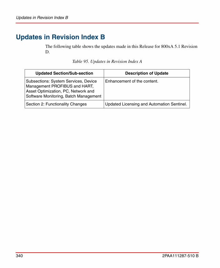
Updates in Revision Index B
340 2PAA111287-510 B
Updates in Revision Index BThe following table shows the updates made in this Release for 800xA 5.1 Revision D.
Table 95. Updates in Revision Index A
Updated Section/Sub-section Description of Update
Subsections: System Services, Device Management PROFIBUS and HART, Asset Optimization, PC, Network and Software Monitoring, Batch Management
Enhancement of the content.
Section 2: Functionality Changes Updated Licensing and Automation Sentinel.


Power and productivityfor a better worldTM
Contact us
Copyright© 2016 ABB.All rights reserved.
2PA
A11
1287
-510
Bwww.abb.com/800xAwww.abb.com/controlsystems