System 5000 m Press Control niL FEED INTERFACE i … · 444 McNALLY DRIVE, NASHVILLE TN 37211 PH...
40
OmniLink 5000 System 5000 Press Control FEED INTERFACE OPERATING MANUAL LINK ELECTRIC & SAFETY CONTROL COMPANY 444 McNALLY DRIVE, NASHVILLE TN 37211 PH (615)-833-4168 FAX (615)-834-1984
Transcript of System 5000 m Press Control niL FEED INTERFACE i … · 444 McNALLY DRIVE, NASHVILLE TN 37211 PH...

Om
niL
ink
5000
System 5000Press Control
FEED INTERFACEOPERATING MANUAL
LINK ELECTRIC & SAFETY CONTROL COMPANY
444 McNALLY DRIVE, NASHVILLE TN 37211
PH (615)-833-4168 FAX (615)-834-1984

Table of Contents
1. INTRODUCTION . . . . . . . . . . . . . . . . . . . . . . . . . . . . . . . . . . . . . . . . . . . . . . . . . . . . . . . . . . . . . . . . . . 1.11.1 Requirements . . . . . . . . . . . . . . . . . . . . . . . . . . . . . . . . . . . . . . . . . . . . . . . . . . . . . . . . . . . . . . . 1.1
2. INSTALLATION . . . . . . . . . . . . . . . . . . . . . . . . . . . . . . . . . . . . . . . . . . . . . . . . . . . . . . . . . . . . . . . . . . 2.12.1 Old Communication Board Connection . . . . . . . . . . . . . . . . . . . . . . . . . . . . . . . . . . . . . . . . . . . 2.12.2 New Communication Board Connection . . . . . . . . . . . . . . . . . . . . . . . . . . . . . . . . . . . . . . . . . . 2.12.3 Coe CPEC/BG1 Interface . . . . . . . . . . . . . . . . . . . . . . . . . . . . . . . . . . . . . . . . . . . . . . . . . . . . . . 2.22.4 Coe BG2 Interface . . . . . . . . . . . . . . . . . . . . . . . . . . . . . . . . . . . . . . . . . . . . . . . . . . . . . . . . . . . 2.32.5 Coe ServoMaster Interface . . . . . . . . . . . . . . . . . . . . . . . . . . . . . . . . . . . . . . . . . . . . . . . . . . . . . 2.42.6 CWP ServoDial II Interface . . . . . . . . . . . . . . . . . . . . . . . . . . . . . . . . . . . . . . . . . . . . . . . . . . . . 2.52.7 CWP ServoDial 2000 Interface . . . . . . . . . . . . . . . . . . . . . . . . . . . . . . . . . . . . . . . . . . . . . . . . . 2.52.8 CWP Servomatic Interface . . . . . . . . . . . . . . . . . . . . . . . . . . . . . . . . . . . . . . . . . . . . . . . . . . . 2.62.9 CWP ServoMax II Interface . . . . . . . . . . . . . . . . . . . . . . . . . . . . . . . . . . . . . . . . . . . . . . . . . . . . 2.72.10 Reliance/Electro-Craft IQ2000/IQ5000 Based Interface . . . . . . . . . . . . . . . . . . . . . . . . . . . . . . 2.72.11 Dallas Feed Interface (EXOR Control) . . . . . . . . . . . . . . . . . . . . . . . . . . . . . . . . . . . . . . . . . . . 2.82.12 Emerson Servo Interface . . . . . . . . . . . . . . . . . . . . . . . . . . . . . . . . . . . . . . . . . . . . . . . . . . . . . . 2.82.13 Indramat CLM Interface . . . . . . . . . . . . . . . . . . . . . . . . . . . . . . . . . . . . . . . . . . . . . . . . . . . . . . . 2.92.14 Indramat DLC Interface . . . . . . . . . . . . . . . . . . . . . . . . . . . . . . . . . . . . . . . . . . . . . . . . . . . . . . . 2.92.15 Indramat SOT Interface . . . . . . . . . . . . . . . . . . . . . . . . . . . . . . . . . . . . . . . . . . . . . . . . . . . . . . 2.102.16 Indramat CLM Version 1.2 Interface . . . . . . . . . . . . . . . . . . . . . . . . . . . . . . . . . . . . . . . . . . . . 2.112.17 Indramat SOT with CLM Version 1.2 Interface. . . . . . . . . . . . . . . . . . . . . . . . . . . . . . . . . . . . 2.112.18 PA Bullet/Edge/Advantage Interface . . . . . . . . . . . . . . . . . . . . . . . . . . . . . . . . . . . . . . . . . . . . 2.122.19 Rapid-Air Interface . . . . . . . . . . . . . . . . . . . . . . . . . . . . . . . . . . . . . . . . . . . . . . . . . . . . . . . . . . 2.13
2.19.1 Rapid-Air Connections with Old Communications board . . . . . . . . . . . . . . . . . . . . . 2.132.19.2 Rapid-Air Connections with New Communications board . . . . . . . . . . . . . . . . . . . . . 2.14
2.20 Unico Interface . . . . . . . . . . . . . . . . . . . . . . . . . . . . . . . . . . . . . . . . . . . . . . . . . . . . . . . . . . . . . 2.152.21 Waddington Interface (MC500 Controller) . . . . . . . . . . . . . . . . . . . . . . . . . . . . . . . . . . . . . . . 2.152.22 Dynamic Feeds Interface . . . . . . . . . . . . . . . . . . . . . . . . . . . . . . . . . . . . . . . . . . . . . . . . . . . . . 2.16
3. CONFIGURATION . . . . . . . . . . . . . . . . . . . . . . . . . . . . . . . . . . . . . . . . . . . . . . . . . . . . . . . . . . 3.13.1 Configuring the Old Communication Board . . . . . . . . . . . . . . . . . . . . . . . . . . . . . . . . . . . . . . . 3.13.2 Configuring the New Communication Board . . . . . . . . . . . . . . . . . . . . . . . . . . . . . . . . . . . . . . . 3.13.3 Setting the New Communication Board Feed Port for RS-232 or RS-485 Operation. . . . . . . . 3.4
4. OPERATION . . . . . . . . . . . . . . . . . . . . . . . . . . . . . . . . . . . . . . . . . . . . . . . . . . . . . . . . . . . . . . . . . . . . . . 4.14.1 Entering Feed Parameters with the Old Communication Board . . . . . . . . . . . . . . . . . . . . . . . . 4.14.2 Entering Feed Parameters with the New Communication Board . . . . . . . . . . . . . . . . . . . . . . . . 4.14.3 Job Storage . . . . . . . . . . . . . . . . . . . . . . . . . . . . . . . . . . . . . . . . . . . . . . . . . . . . . . . . . . . . . . . . . 4.24.4 Job Recall . . . . . . . . . . . . . . . . . . . . . . . . . . . . . . . . . . . . . . . . . . . . . . . . . . . . . . . . . . . . . . . . . . 4.3
5. INTERFACING TO OTHER FEEDS OR DEVICES . . . . . . . . . . . . . . . . . . . . . . . . . . . . . . . . . . . . . . . 5.1
Appendix A - Upgrading Link Equipment . . . . . . . . . . . . . . . . . . . . . . . . . . . . . . . . . . . . . . . . . . . . A.1A.1 General Chip Changing Rules . . . . . . . . . . . . . . . . . . . . . . . . . . . . . . . . . . . . . . . . . . . . . . . . . A.1A.2 System 1100 Tonnage Monitor Upgrade Procedure . . . . . . . . . . . . . . . . . . . . . . . . . . . . . . . . A.1
A.2.1 System 1100 OIT Software Upgrade Procedure . . . . . . . . . . . . . . . . . . . . . . . . . . . . . A.1A.2.2 System 1100 Motherboard Software Upgrade Procedure . . . . . . . . . . . . . . . . . . . . . . A.2
A.3 OmniLink 5000 Upgrade Procedure . . . . . . . . . . . . . . . . . . . . . . . . . . . . . . . . . . . . . . . . . . . . . A.3A.3.1 OmniLink OIT Communications Board Upgrade Procedure . . . . . . . . . . . . . . . . . . . A.3A.3.2 OmniLink OIT Software Upgrade Procedure . . . . . . . . . . . . . . . . . . . . . . . . . . . . . . . A.4

A.3.3 OmniLink OIT Communications Card Software Upgrade Procedure . . . . . . . . . . . . . A.4A.3.4 OmniLink Logic Module Upgrade Procedure . . . . . . . . . . . . . . . . . . . . . . . . . . . . . . . A.5A.3.5 OmniLink Die Protection Module Software Upgrade Procedure . . . . . . . . . . . . . . . . A.5A.3.6 OmniLink Tonnage Monitor Module Software Upgrade Procedure . . . . . . . . . . . . . . A.6A.3.7 OmniLink Auto-Setup Module Software Upgrade Procedure . . . . . . . . . . . . . . . . . . . A.6
OmniLink 5000 Feed Manual December 13, 1999
1.1 Manual Rev 2.3
1. INTRODUCTION
The OmniLink 5000 Operator InterfaceTerminal (OIT) is equipped with a serialcommunications card and can be interfaced tocertain electronic roll feeds. This interface allowsfeed length, feed speed, and feed acceleration (oncertain feeds) to be programmed from the OmniLinkOIT. These parameters are included in the jobstorage area of the system 5000 and automaticallytransferred to the roll feed when a job is recalled.
There are two different communication boardsused on the OmniLink 5000. The older style boardonly supports certain feeds and provides for thedownloading of tonnage waveforms. The newercommunications board supports more feeds, userselectable units for the feeds (for instance, inch andmillimeter), tonnage waveform downloads, networkoperation, and other planned future enhancements.OmniLink controls shipped after July 1998 have thenewer communications board installed as standard.If the features of the newer communications boardare desired for an OmniLink control with the olderboard installed, a retrofit kit is available to upgradethe control. Contact Link for details and pricing.
Support for new feeds is added on a regularbasis by Link, so whether or not the new or oldcommunication board is installed, a softwareupgrade may be required for recently added feeds.Contact Link with the serial number of theOmniLink control and the feed manufacturer andmodel number so that the necessary feed kit andsoftware updates can be determined.
1.1 Requirements
In order to connect an electronic roll feed to theOmniLink 5000 the following items are necessary:
� A feed interface cable to connect the OmniLinkOIT communication card to the electronic rollfeed. The section in this manual on eachsupported feed will give the Link part number ofthe cable appropriate for the feed as well as aconnection diagram.
OmniLink 5000 Feed Manual December 13, 1999
1.2 Manual Rev 2.3
� The roll feed must be supported by theOmniLink 5000. Supported feeds at the timethis manual was published include:
� Coe CPEC/BG1� Coe BG2 **� Coe ServoMaster **� Dallas (EXOR Control) **� Dynamic Feeds **� Reliance/Electro-Craft IQ2000/IQ5000� Emerson Roll Feed� Indramat CLM/SOT/DLC� Indramat CLM/SOT Ver 1.2 **� CWP ServoDial II **� CWP ServoDial 2000� CWP Servomatic **� CWP ServoMax II **� PA Edge/Bullet/Advantage **� RapidAir Feed� Rowe (IQ2000/5000 Based)� Unico Type 1� Unico Type 2� Vamco Feeds (except Pulsar)� Waddington Feed
** = Feed supported only on newcommunications card.

OmniLink 5000 Feed Manual December 13, 1999
2.1 Manual Rev 2.3
2. INSTALLATION
In most cases, installation consists of simplyconnecting the appropriate cable between theOmniLink 5000 OIT and the feed. Exceptions tothis are noted in the sections for each feed.
There are two different communication boardsused on the OmniLink 5000. The older style boardonly supports certain feeds and provides for thedownloading of tonnage waveforms. The newercommunications board supports more feeds, userselectable units for the feeds (for instance, inch andmillimeter), tonnage waveform downloads, networkoperation, and other planned future enhancements.OmniLink controls shipped after July 1998 have thenewer communications board installed as standard.If the features of the newer communications boardare desired for an OmniLink control with the olderboard installed, a retrofit kit is available to upgradethe control. Contact Link for details and pricing.
The connection to the OmniLink OITdepends on whether the old or new communicationboard is installed. Sections 2.1 and 2.2 show whichport to use on each kind of communication board.
2.1 Old Communication Board Connection
The older communication board has 4connectors and looks like figure 2.1 as viewed fromthe back panel of the OmniLink OIT.
Figure 2.1: Back panel view of oldcommunications board
For this board, serial port #1 (see figure 2.1) isintended for use with electronic roll feeds. Thisinterface conforms to RS-232C specifications. Datais transmitted and received as ASCII characters with1 start bit, 8 data bits, 2 stop bits, no parity, fullduplex, and 9600 baud.
2.2 New Communication Board Connection
The new communication board has 5 connectorsand looks like figure 2.2 as viewed from the backpanel of the OmniLink OIT.
Figure 2.2: Back panel view of newcommunications board
For this board, serial port 4 is intended for feed
OmniLink 5000 Feed Manual December 13, 1999
2.2 Manual Rev 2.3
interface. This port is jumper selectable as a RS-232C port or a RS-485 port depending on the needsof the feed. The data bits, stop bits, and baud rateare all configurable (see section 3 for details).
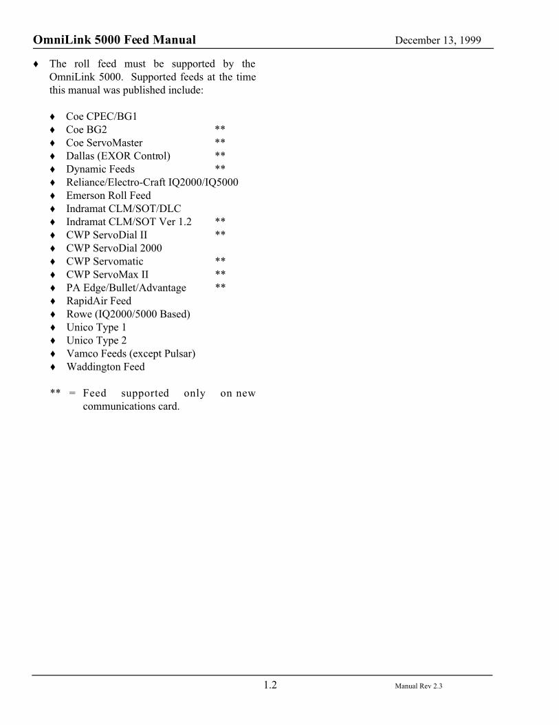
2.3 Coe CPEC/BG1 Interface
The connection to a Coe CPEC or BG1Electronic Feed is as follows:
Table 2.1Coe CPEC/BG1 Connections
Link PN 100812
OmniLink Feed Port
Function / Color Coe CommPort
Pin 1(GND)
Ground (WHITE) GND
Pin 2(RXD)
Receive datafrom feed(BLACK)
Transmit(TXD)
Pin 3(TXD)
Transmit data tofeed (RED)
Receive(RXD)
Notes:
� The communication should be set for 9600baud, 7 data bits, odd parity, 2 stop bits.
� The feed length and speed thumb wheels must
be set at zero or the settings from the serial portwill be ignored.
� Due to the operation of the feed controller, thepresent feed length and speed are held in theOmniLink 5000 OIT. These settings aredisplayed in the feed screen without requestingany data from the feed controller. This isnecessary because the feed controller must behalted (any feed in progress stops) in order torequest present settings. When a new feedlength or speed is entered, the feed controller ishalted, the setting is transmitted to thecontroller, the new setting is requested forverification with the desired value, the feedcontroller program is re-initiated, and thepresent setting is updated in the OmniLink 5000OIT. Failure of the feed to return the samesetting as transmitted will cause the display toshow zeros for that parameter if the oldcommunications board is installed, or to give acommunications error status in the feed screenfor the new communications board. When thisinterface is first installed, the present settingswill not be initialized and may indicate anysetting.
OmniLink 5000 Feed Manual December 13, 1999
2.3 Manual Rev 2.3
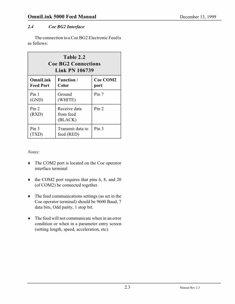
2.4 Coe BG2 Interface
The connection to a Coe BG2 Electronic Feed isas follows:
Table 2.2Coe BG2 Connections
Link PN 106739
OmniLinkFeed Port
Function /Color
Coe COM2port
Pin 1(GND)
Ground(WHITE)
Pin 7
Pin 2(RXD)
Receive datafrom feed(BLACK)
Pin 2
Pin 3(TXD)
Transmit data tofeed (RED)
Pin 3
Notes:
� The COM2 port is located on the Coe operatorinterface terminal
� the COM2 port requires that pins 6, 8, and 20(of COM2) be connected together.
� The feed communications settings (as set in theCoe operator terminal) should be 9600 Baud, 7data bits, Odd parity, 1 stop bit.
� The feed will not communicate when in an errorcondition or when in a parameter entry screen(setting length, speed, acceleration, etc).
OmniLink 5000 Feed Manual December 13, 1999
2.4 Manual Rev 2.3
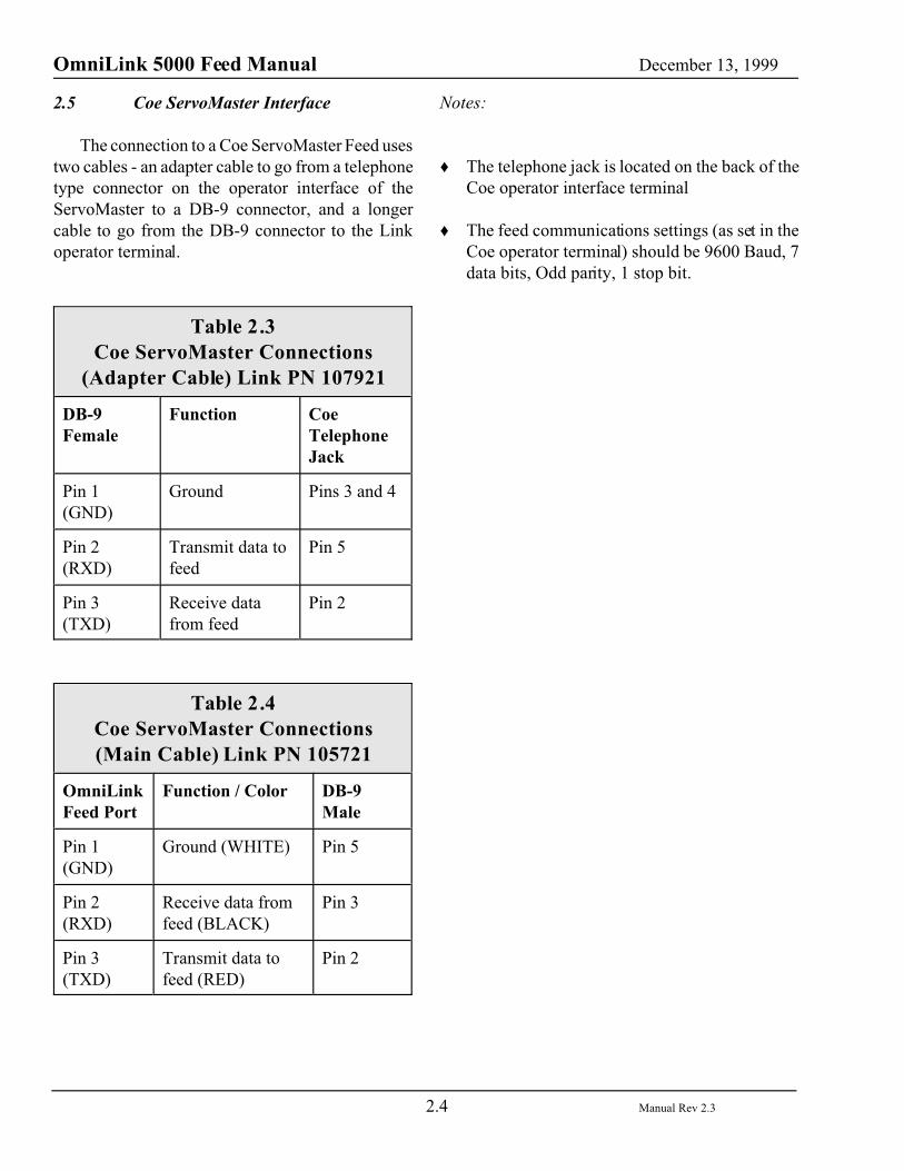
2.5 Coe ServoMaster Interface
The connection to a Coe ServoMaster Feed usestwo cables - an adapter cable to go from a telephonetype connector on the operator interface of theServoMaster to a DB-9 connector, and a longercable to go from the DB-9 connector to the Linkoperator terminal.
Table 2.3Coe ServoMaster Connections
(Adapter Cable) Link PN 107921
DB-9Female
Function CoeTelephoneJack
Pin 1(GND)
Ground Pins 3 and 4
Pin 2(RXD)
Transmit data tofeed
Pin 5
Pin 3(TXD)
Receive datafrom feed
Pin 2
Table 2.4Coe ServoMaster Connections(Main Cable) Link PN 105721
OmniLinkFeed Port
Function / Color DB-9Male
Pin 1(GND)
Ground (WHITE) Pin 5
Pin 2(RXD)
Receive data fromfeed (BLACK)
Pin 3
Pin 3(TXD)
Transmit data tofeed (RED)
Pin 2
Notes:
� The telephone jack is located on the back of theCoe operator interface terminal
� The feed communications settings (as set in theCoe operator terminal) should be 9600 Baud, 7data bits, Odd parity, 1 stop bit.
OmniLink 5000 Feed Manual December 13, 1999
2.5 Manual Rev 2.3
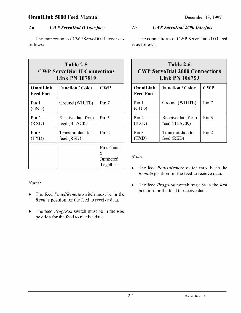
2.6 CWP ServoDial II Interface
The connection to a CWP ServoDial II feed is asfollows:
Table 2.5CWP ServoDial II Connections
Link PN 107819
OmniLinkFeed Port
Function / Color CWP
Pin 1(GND)
Ground (WHITE) Pin 7
Pin 2(RXD)
Receive data fromfeed (BLACK)
Pin 3
Pin 3(TXD)
Transmit data tofeed (RED)
Pin 2
Pins 4 and5JumperedTogether
Notes:
� The feed Panel/Remote switch must be in theRemote position for the feed to receive data.
� The feed Prog/Run switch must be in the Runposition for the feed to receive data.
2.7 CWP ServoDial 2000 Interface
The connection to a CWP ServoDial 2000 feedis as follows:
Table 2.6CWP ServoDial 2000 Connections
Link PN 106759
OmniLinkFeed Port
Function / Color CWP
Pin 1(GND)
Ground (WHITE) Pin 7
Pin 2(RXD)
Receive data fromfeed (BLACK)
Pin 3
Pin 3(TXD)
Transmit data tofeed (RED)
Pin 2
Notes:
� The feed Panel/Remote switch must be in theRemote position for the feed to receive data.
� The feed Prog/Run switch must be in the Runposition for the feed to receive data.

OmniLink 5000 Feed Manual December 13, 1999
2.6 Manual Rev 2.3
2.8 CWP Servomatic Interface
The connection to a CWP Servomatic Feed is alittle more involved than simply plugging in a cable.The servo control used in this feed, a reliance PRO-200, is capable of “talking” to its own OIT or theOmniLink OIT but not both at the same time. Asmall circuit board (Link PN 107632) with someconnectors and a switch is used to connect all threeunits (Link OIT, feed OIT, and servo control) sothat a switch can select whether the feed OIT or theOmniLink OIT is able to communicate with theservo control. The circuit board is installed asshown in figure 2.3.
Figure 2.3: Interface board for PRO-200 basedfeeds (Link PN 107632).
The feed OIT originally plugs into port 5 of thePRO-200. Disconnect the feed OIT at port 5 of thePRO-200 and plug it into the matching connector onthe small interface circuit board (there is only oneconnector that will work). Plug the connector fromthe small interface circuit board (connected by fivewires) into port 5 of the PRO-200 (again, there isonly one connector that will work). A cable issupplied by Link that goes from the DB-9 connectoron the small interface circuit board to the OmniLink5000 OIT. The connections on that cable are asfollows:
Table 2.7CWP Servomatic Connections
Link PN 106744
OmniLinkFeed Port
Function /Color
Small CircuitBoard DB-9Connector
Pin 1(GND)
Ground(WHITE)
Pin 5
Pin 2(RXD)
Receive datafrom feed(BLACK)
Pin 3
Pin 3(TXD)
Transmit datato feed (RED)
Pin 2
Notes:
None.
OmniLink 5000 Feed Manual December 13, 1999
2.7 Manual Rev 2.3
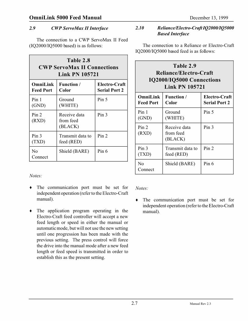
2.9 CWP ServoMax II Interface
The connection to a CWP ServoMax II Feed(IQ2000/IQ5000 based) is as follows:
Table 2.8CWP ServoMax II Connections
Link PN 105721
OmniLinkFeed Port
Function /Color
Electro-CraftSerial Port 2
Pin 1(GND)
Ground(WHITE)
Pin 5
Pin 2(RXD)
Receive datafrom feed(BLACK)
Pin 3
Pin 3(TXD)
Transmit data tofeed (RED)
Pin 2
NoConnect
Shield (BARE) Pin 6
Notes:
� The communication port must be set forindependent operation (refer to the Electro-Craftmanual).
� The application program operating in theElectro-Craft feed controller will accept a newfeed length or speed in either the manual orautomatic mode, but will not use the new settinguntil one progression has been made with theprevious setting. The press control will forcethe drive into the manual mode after a new feedlength or feed speed is transmitted in order toestablish this as the present setting.
2.10 Reliance/Electro-Craft IQ2000/IQ5000Based Interface
The connection to a Reliance or Electro-CraftIQ2000/IQ5000 based feed is as follows:
Table 2.9Reliance/Electro-Craft
IQ2000/IQ5000 ConnectionsLink PN 105721
OmniLinkFeed Port
Function /Color
Electro-CraftSerial Port 2
Pin 1(GND)
Ground(WHITE)
Pin 5
Pin 2(RXD)
Receive datafrom feed(BLACK)
Pin 3
Pin 3(TXD)
Transmit data tofeed (RED)
Pin 2
NoConnect
Shield (BARE) Pin 6
Notes:
� The communication port must be set forindependent operation (refer to the Electro-Craftmanual).
OmniLink 5000 Feed Manual December 13, 1999
2.8 Manual Rev 2.3
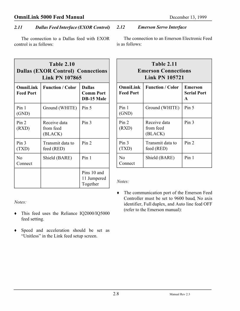
2.11 Dallas Feed Interface (EXOR Control)
The connection to a Dallas feed with EXORcontrol is as follows:
Table 2.10Dallas (EXOR Control) Connections
Link PN 107865
OmniLinkFeed Port
Function / Color DallasComm PortDB-15 Male
Pin 1(GND)
Ground (WHITE) Pin 5
Pin 2(RXD)
Receive datafrom feed(BLACK)
Pin 3
Pin 3(TXD)
Transmit data tofeed (RED)
Pin 2
NoConnect
Shield (BARE) Pin 1
Pins 10 and11 JumperedTogether
Notes:
� This feed uses the Reliance IQ2000/IQ5000feed setting.
� Speed and acceleration should be set as“Unitless” in the Link feed setup screen.
2.12 Emerson Servo Interface
The connection to an Emerson Electronic Feedis as follows:
Table 2.11Emerson Connections
Link PN 105721
OmniLinkFeed Port
Function / Color EmersonSerial PortA
Pin 1(GND)
Ground (WHITE) Pin 5
Pin 2(RXD)
Receive datafrom feed(BLACK)
Pin 3
Pin 3(TXD)
Transmit data tofeed (RED)
Pin 2
NoConnect
Shield (BARE) Pin 1
Notes:
� The communication port of the Emerson FeedController must be set to 9600 baud, No axisidentifier, Full duplex, and Auto line feed OFF(refer to the Emerson manual):
OmniLink 5000 Feed Manual December 13, 1999
2.9 Manual Rev 2.3
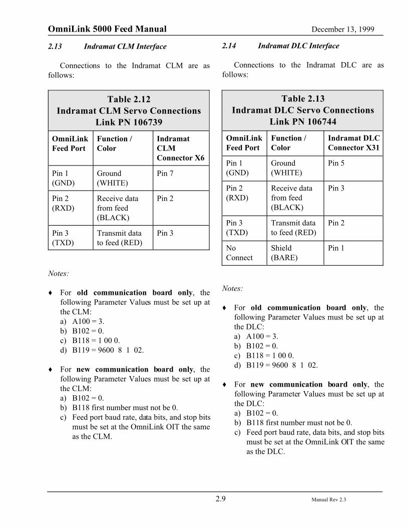
2.13 Indramat CLM Interface
Connections to the Indramat CLM are asfollows:
Table 2.12Indramat CLM Servo Connections
Link PN 106739
OmniLinkFeed Port
Function /Color
IndramatCLMConnector X6
Pin 1(GND)
Ground(WHITE)
Pin 7
Pin 2(RXD)
Receive datafrom feed(BLACK)
Pin 2
Pin 3(TXD)
Transmit datato feed (RED)
Pin 3
Notes:
� For old communication board only, thefollowing Parameter Values must be set up atthe CLM:a) A100 = 3.b) B102 = 0.c) B118 = 1 00 0.d) B119 = 9600 8 1 02.
� For new communication board only, thefollowing Parameter Values must be set up atthe CLM:a) B102 = 0.b) B118 first number must not be 0.c) Feed port baud rate, data bits, and stop bits
must be set at the OmniLink OIT the sameas the CLM.
2.14 Indramat DLC Interface
Connections to the Indramat DLC are asfollows:
Table 2.13Indramat DLC Servo Connections
Link PN 106744
OmniLinkFeed Port
Function /Color
Indramat DLCConnector X31
Pin 1(GND)
Ground(WHITE)
Pin 5
Pin 2(RXD)
Receive datafrom feed(BLACK)
Pin 3
Pin 3(TXD)
Transmit datato feed (RED)
Pin 2
NoConnect
Shield(BARE)
Pin 1
Notes:
� For old communication board only, thefollowing Parameter Values must be set up atthe DLC:a) A100 = 3.b) B102 = 0.c) B118 = 1 00 0.d) B119 = 9600 8 1 02.
� For new communication board only, thefollowing Parameter Values must be set up atthe DLC:a) B102 = 0.b) B118 first number must not be 0.c) Feed port baud rate, data bits, and stop bits
must be set at the OmniLink OIT the sameas the DLC.
OmniLink 5000 Feed Manual December 13, 1999
2.10 Manual Rev 2.3
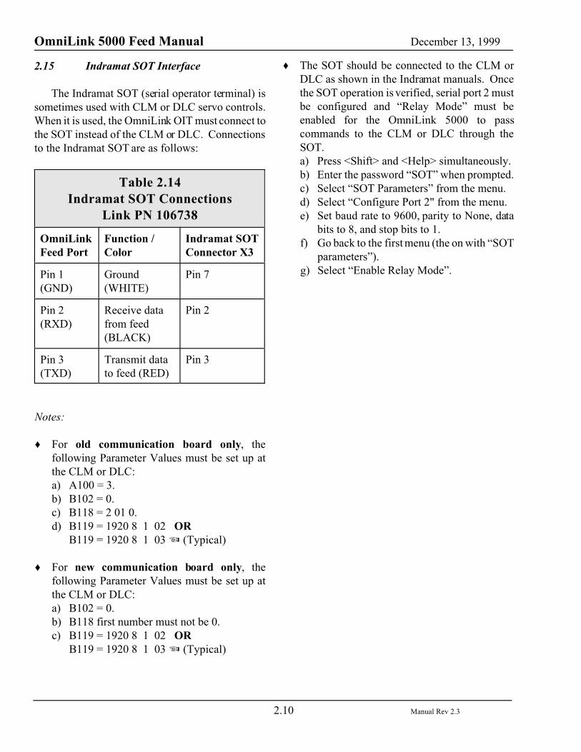
2.15 Indramat SOT Interface
The Indramat SOT (serial operator terminal) issometimes used with CLM or DLC servo controls.When it is used, the OmniLink OIT must connect tothe SOT instead of the CLM or DLC. Connectionsto the Indramat SOT are as follows:
Table 2.14Indramat SOT Connections
Link PN 106738
OmniLinkFeed Port
Function /Color
Indramat SOTConnector X3
Pin 1(GND)
Ground(WHITE)
Pin 7
Pin 2(RXD)
Receive datafrom feed(BLACK)
Pin 2
Pin 3(TXD)
Transmit datato feed (RED)
Pin 3
Notes:
� For old communication board only, thefollowing Parameter Values must be set up atthe CLM or DLC:a) A100 = 3.b) B102 = 0.c) B118 = 2 01 0.d) B119 = 1920 8 1 02 OR
B119 = 1920 8 1 03 7 (Typical)
� For new communication board only, thefollowing Parameter Values must be set up atthe CLM or DLC:a) B102 = 0.b) B118 first number must not be 0.c) B119 = 1920 8 1 02 OR
B119 = 1920 8 1 03 7 (Typical)
� The SOT should be connected to the CLM orDLC as shown in the Indramat manuals. Oncethe SOT operation is verified, serial port 2 mustbe configured and “Relay Mode” must beenabled for the OmniLink 5000 to passcommands to the CLM or DLC through theSOT.a) Press <Shift> and <Help> simultaneously.b) Enter the password “SOT” when prompted.c) Select “SOT Parameters” from the menu.d) Select “Configure Port 2" from the menu.e) Set baud rate to 9600, parity to None, data
bits to 8, and stop bits to 1.f) Go back to the first menu (the on with “SOT
parameters”).g) Select “Enable Relay Mode”.
OmniLink 5000 Feed Manual December 13, 1999
2.11 Manual Rev 2.3
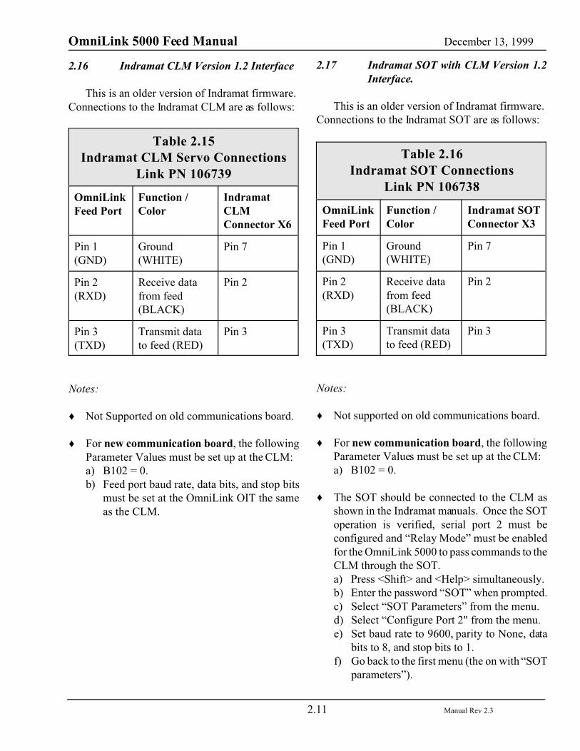
2.16 Indramat CLM Version 1.2 Interface
This is an older version of Indramat firmware. Connections to the Indramat CLM are as follows:
Table 2.15Indramat CLM Servo Connections
Link PN 106739
OmniLinkFeed Port
Function /Color
IndramatCLMConnector X6
Pin 1(GND)
Ground(WHITE)
Pin 7
Pin 2(RXD)
Receive datafrom feed(BLACK)
Pin 2
Pin 3(TXD)
Transmit datato feed (RED)
Pin 3
Notes:
� Not Supported on old communications board.
� For new communication board, the followingParameter Values must be set up at the CLM:a) B102 = 0.b) Feed port baud rate, data bits, and stop bits
must be set at the OmniLink OIT the sameas the CLM.
2.17 Indramat SOT with CLM Version 1.2Interface.
This is an older version of Indramat firmware. Connections to the Indramat SOT are as follows:
Table 2.16Indramat SOT Connections
Link PN 106738
OmniLinkFeed Port
Function /Color
Indramat SOTConnector X3
Pin 1(GND)
Ground(WHITE)
Pin 7
Pin 2(RXD)
Receive datafrom feed(BLACK)
Pin 2
Pin 3(TXD)
Transmit datato feed (RED)
Pin 3
Notes:
� Not supported on old communications board.
� For new communication board, the followingParameter Values must be set up at the CLM:a) B102 = 0.
� The SOT should be connected to the CLM asshown in the Indramat manuals. Once the SOToperation is verified, serial port 2 must beconfigured and “Relay Mode” must be enabledfor the OmniLink 5000 to pass commands to theCLM through the SOT.a) Press <Shift> and <Help> simultaneously.b) Enter the password “SOT” when prompted.c) Select “SOT Parameters” from the menu.d) Select “Configure Port 2" from the menu.e) Set baud rate to 9600, parity to None, data
bits to 8, and stop bits to 1.f) Go back to the first menu (the on with “SOT
parameters”).
OmniLink 5000 Feed Manual December 13, 1999
2.12 Manual Rev 2.3
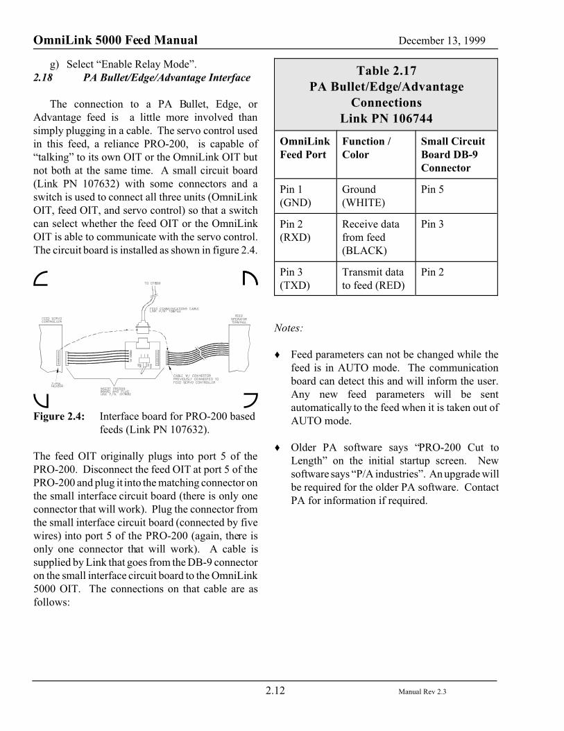
g) Select “Enable Relay Mode”.2.18 PA Bullet/Edge/Advantage Interface
The connection to a PA Bullet, Edge, orAdvantage feed is a little more involved thansimply plugging in a cable. The servo control usedin this feed, a reliance PRO-200, is capable of“talking” to its own OIT or the OmniLink OIT butnot both at the same time. A small circuit board(Link PN 107632) with some connectors and aswitch is used to connect all three units (OmniLinkOIT, feed OIT, and servo control) so that a switchcan select whether the feed OIT or the OmniLinkOIT is able to communicate with the servo control.The circuit board is installed as shown in figure 2.4.
Figure 2.4: Interface board for PRO-200 basedfeeds (Link PN 107632).
The feed OIT originally plugs into port 5 of thePRO-200. Disconnect the feed OIT at port 5 of thePRO-200 and plug it into the matching connector onthe small interface circuit board (there is only oneconnector that will work). Plug the connector fromthe small interface circuit board (connected by fivewires) into port 5 of the PRO-200 (again, there isonly one connector that will work). A cable issupplied by Link that goes from the DB-9 connectoron the small interface circuit board to the OmniLink5000 OIT. The connections on that cable are asfollows:
Table 2.17PA Bullet/Edge/Advantage
ConnectionsLink PN 106744
OmniLinkFeed Port
Function /Color
Small CircuitBoard DB-9Connector
Pin 1(GND)
Ground(WHITE)
Pin 5
Pin 2(RXD)
Receive datafrom feed(BLACK)
Pin 3
Pin 3(TXD)
Transmit datato feed (RED)
Pin 2
Notes:
� Feed parameters can not be changed while thefeed is in AUTO mode. The communicationboard can detect this and will inform the user.Any new feed parameters will be sentautomatically to the feed when it is taken out ofAUTO mode.
� Older PA software says “PRO-200 Cut toLength” on the initial startup screen. Newsoftware says “P/A industries”. An upgrade willbe required for the older PA software. ContactPA for information if required.
OmniLink 5000 Feed Manual December 13, 1999
2.13 Manual Rev 2.3
2.19 Rapid-Air Interface
The Rapid-Air interface is somewhat differentfrom most of the feed interfaces. Many of the feedfunctions are controlled from a small keypad andscreen that connects to the only availablecommunications port on the feed control itself. Aspecial adapter board must be used to communicatewith the feed. In addition, the old communicationsboard needs an RS-232 to RS-485 converter toenable the System 5000 to communicate with thefeed. The new communications board feed port canbe configured to be RS-232 or RS-485.
2.19.1 Rapid-Air Connections with OldCommunications board
The connection to a Rapid-Air Feed from the oldcommunications board is as follows:
Table 2.18OmniLink OIT To RS-485
Converter Connections for OldCommunication Board
OmniLinkFeed Port
Function RS-485Converter
Pin 1(GND)
Ground Pin 7 (GND)
Pin 2(RXD)
Receive datafrom feed
Pin 2 (TXD)
Pin 3(TXD)
Transmit datato feed
Pin 3 (RXD)
Table 2.19RS-485 Converter to Rapid-Air
Connections for Old Communication
RS-485Converter
Function Rapid-AirConnector J58
Ground Ground Pin 5
TXD+ Transmit + Pin 8
TXD- Transmit- Pin 9
RXD+ Receive+ Pin 6
RXD- Receive- Pin 7
Notes:
� Rapid-Air has used two different servo controlsat different times, the Pacific Scientific SC750series, and the SC950 series. The commconnector is the same on each of the controls.
� The connections from the operator terminal toJ58 must also remain in place.
� On the SC750 series of servo controls, Input 14(Pin 6 of J56) must be low to enable remotedownload of feed parameters. On the SC950series of servo controls, there is a circuit boardbelow the communications connector withterminals on it. If the wires to the board haveresistors at the terminals, then terminal 14should be disconnected to enablecommunications. Call Rapid-Air if there is anytrouble in identifying these inputs.
� If the feed is powered down but the System5000 is not, the feed will lose the current length,speed, and acceleration values but the 5000 willnot know that. To reset the values in the feed,the feed screen must be entered and the lengthreprogrammed. This will reset all three values.If both units are powered down, everything willbe reset automatically.
OmniLink 5000 Feed Manual December 13, 1999
2.14 Manual Rev 2.3
2.19.2 Rapid-Air Connections with NewCommunications board
The connection to a Rapid-Air Feed from the newcommunications board is as follows:
Table 2.20OmniLink OIT to Rapid-Air
Connections for NewCommunication Board
Link PN 107833
OmniLinkPort 4
Function /Color
Rapid-AirConnector J58
Ground Ground(GREEN/W)
Pin 5
RXD+ Receive+(ORANGE/W)
Pin 6
RXD- Receive-(W/ORANGE)
Pin 7
TXD+ Transmit +(BLUE/W)
Pin 8
TXD- Transmit-(W/BLUE)
Pin 9
Notes:
� Link makes a small adapter board ( PN 107858)that plugs into the Rapid-Air communicationsport to provide 2 communications connectors.The Rapid-Air operator interface (if present)plugs into one connector (either one), and theLink feed interface cable plugs into the other.
� Rapid-Air has used two different servo controlsat different times, the Pacific Scientific SC750series, and the SC950 series. Thecommunications connector is the same on eachof the controls.
� The connections from the operator terminal toJ58 must also remain in place.
� On the SC750 series of servo controls, Input 14(Pin 6 of J56) must be low to enable remotedownload of feed parameters. On the SC950series of servo controls, there is a circuit boardbelow the communications connector withterminals on it. If the wires to the board haveresistors at the terminals, then terminal 14should be disconnected to enablecommunications. Call Rapid-Air if there is anytrouble in identifying these inputs.
� Port 4 of the new communications board mustbe jumpered for RS-485 operation. See section3.3 for configuration information.
� On some older versions of Rapid-Air software,if the feed is powered down but the System5000 is not, the feed will lose the current length,speed, and acceleration values but the 5000 willnot know that. To reset the values in the feed,the feed screen must be entered and the lengthreprogrammed. This will reset all three values.If both units are powered down, everything willbe reset automatically. Contact Rapid-Air forinformation on software updates to correct this.
� Some version of Rapid-Air software do notsupport a read back of the values sent to it.Always try the “Rapid Air Type 2" feed typefirst to see if this is supported. If not, “RapidAir Type 1" can be used. It is recommended tocontact Rapid-Air for a software update if this isthe case.
OmniLink 5000 Feed Manual December 13, 1999
2.15 Manual Rev 2.3
2.20 Unico Interface
The connection to a Unico Feed is as follows:
Table 2.21Unico Connections
Link PN 106746
OmniLinkFeed Port
Function /Color
Unico CommBoard 25 Pin232 Connector
Pin 1(GND)
Ground(WHITE)
Pin 7 (GND)
Pin 2(RXD)
Receive datafrom feed(BLACK)
Pin 2 (TXD)
Pin 3(TXD)
Transmit datato feed (RED)
Pin 3 (RXD)
Notes:
� Pins 4 and 5 on the Unico 232 communicationsconnector must be tied together (RTS to CTS).
� There are two different operating systems in useon Unico feeds. The System 5000 supportsthese as “Type 1" and “Type 2" Unico feeds.You may have to experiment to find out whichtype you have.
2.21 Waddington Interface (MC500Controller)
The connection to a Waddington Feed is as follows:
Table 2.22Waddington Connections
Link PN 106748
OmniLinkFeed Port
Function /Color
WaddingtonConnector J5
Pin 1(GND)
Ground(WHITE)
Pin 7
Pin 2(RXD)
Receive datafrom feed(BLACK)
Pin 3
Pin 3(TXD)
Transmit datato feed (RED)
Pin 2
NoConnect
Shield Pin 1
Notes:
� The communication port of the WaddingtonFeed Controller must be set to 9600 baud (seeWaddington manual).
OmniLink 5000 Feed Manual December 13, 1999
2.16 Manual Rev 2.3
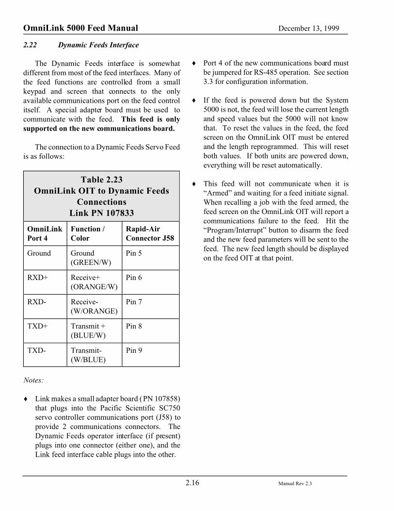
2.22 Dynamic Feeds Interface
The Dynamic Feeds interface is somewhatdifferent from most of the feed interfaces. Many ofthe feed functions are controlled from a smallkeypad and screen that connects to the onlyavailable communications port on the feed controlitself. A special adapter board must be used tocommunicate with the feed. This feed is onlysupported on the new communications board.
The connection to a Dynamic Feeds Servo Feedis as follows:
Table 2.23OmniLink OIT to Dynamic Feeds
ConnectionsLink PN 107833
OmniLinkPort 4
Function /Color
Rapid-AirConnector J58
Ground Ground(GREEN/W)
Pin 5
RXD+ Receive+(ORANGE/W)
Pin 6
RXD- Receive-(W/ORANGE)
Pin 7
TXD+ Transmit +(BLUE/W)
Pin 8
TXD- Transmit-(W/BLUE)
Pin 9
Notes:
� Link makes a small adapter board ( PN 107858)that plugs into the Pacific Scientific SC750servo controller communications port (J58) toprovide 2 communications connectors. TheDynamic Feeds operator interface (if present)plugs into one connector (either one), and theLink feed interface cable plugs into the other.
� Port 4 of the new communications board mustbe jumpered for RS-485 operation. See section3.3 for configuration information.
� If the feed is powered down but the System5000 is not, the feed will lose the current lengthand speed values but the 5000 will not knowthat. To reset the values in the feed, the feedscreen on the OmniLink OIT must be enteredand the length reprogrammed. This will resetboth values. If both units are powered down,everything will be reset automatically.
� This feed will not communicate when it is“Armed” and waiting for a feed initiate signal.When recalling a job with the feed armed, thefeed screen on the OmniLink OIT will report acommunications failure to the feed. Hit the“Program/Interrupt” button to disarm the feedand the new feed parameters will be sent to thefeed. The new feed length should be displayedon the feed OIT at that point.
OmniLink 5000 Feed Manual December 13, 1999
3.1 Manual Rev 2.3
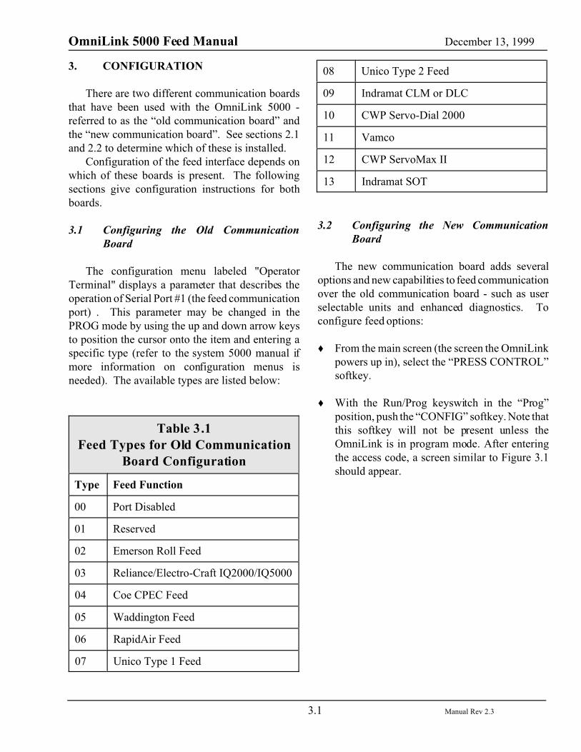
3. CONFIGURATION
There are two different communication boardsthat have been used with the OmniLink 5000 -referred to as the “old communication board” andthe “new communication board”. See sections 2.1and 2.2 to determine which of these is installed.
Configuration of the feed interface depends onwhich of these boards is present. The followingsections give configuration instructions for bothboards.
3.1 Configuring the Old CommunicationBoard
The configuration menu labeled "OperatorTerminal" displays a parameter that describes theoperation of Serial Port #1 (the feed communicationport) . This parameter may be changed in thePROG mode by using the up and down arrow keysto position the cursor onto the item and entering aspecific type (refer to the system 5000 manual ifmore information on configuration menus isneeded). The available types are listed below:
Table 3.1Feed Types for Old Communication
Board Configuration
Type Feed Function
00 Port Disabled
01 Reserved
02 Emerson Roll Feed
03 Reliance/Electro-Craft IQ2000/IQ5000
04 Coe CPEC Feed
05 Waddington Feed
06 RapidAir Feed
07 Unico Type 1 Feed
08 Unico Type 2 Feed
09 Indramat CLM or DLC
10 CWP Servo-Dial 2000
11 Vamco
12 CWP ServoMax II
13 Indramat SOT
3.2 Configuring the New CommunicationBoard
The new communication board adds severaloptions and new capabilities to feed communicationover the old communication board - such as userselectable units and enhanced diagnostics. Toconfigure feed options:
� From the main screen (the screen the OmniLinkpowers up in), select the “PRESS CONTROL”softkey.
� With the Run/Prog keyswitch in the “Prog”position, push the “CONFIG” softkey. Note thatthis softkey will not be present unless theOmniLink is in program mode. After enteringthe access code, a screen similar to Figure 3.1should appear.
OmniLink 5000 Feed Manual December 13, 1999
3.2 Manual Rev 2.3
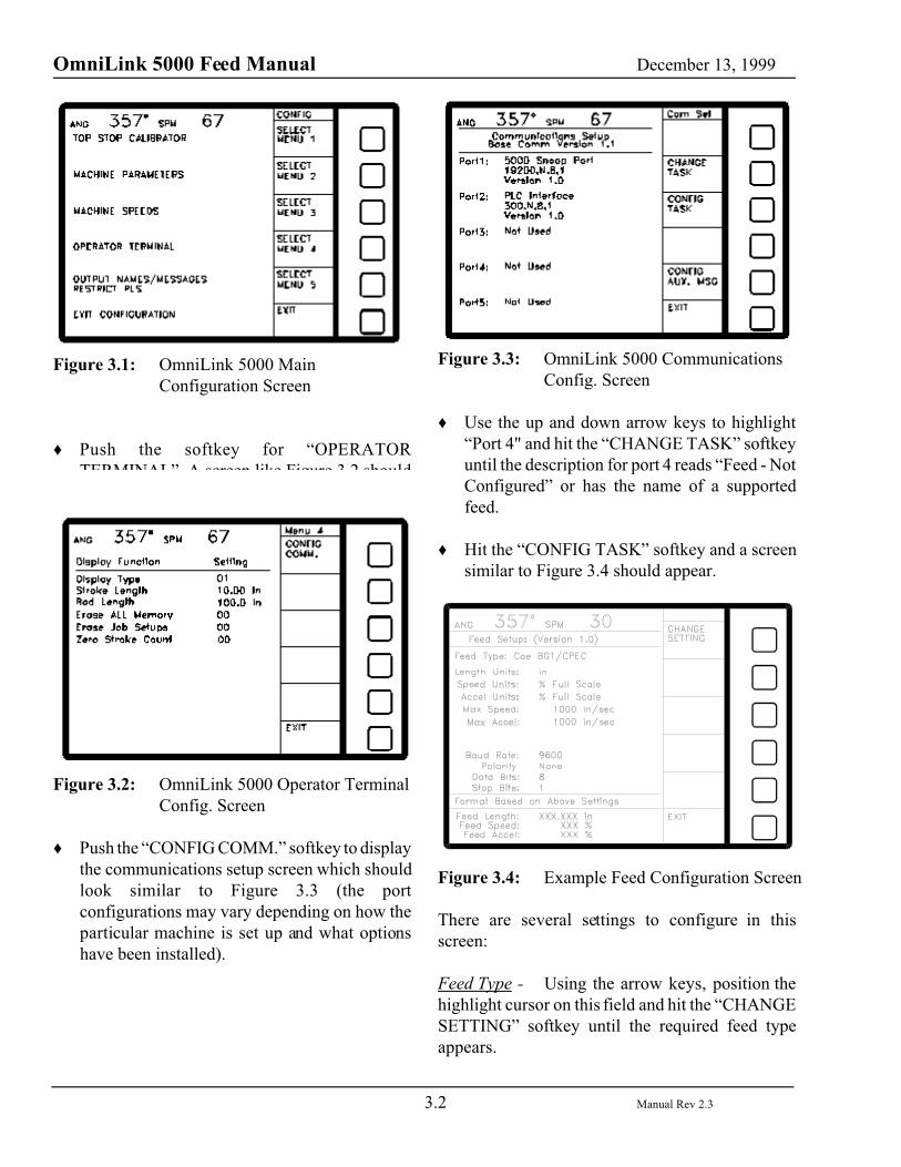
Figure 3.1: OmniLink 5000 MainConfiguration Screen
� Push the softkey for “OPERATORTERMINAL”. A screen like Figure 3.2 shouldappear.
Figure 3.2: OmniLink 5000 Operator TerminalConfig. Screen
� Push the “CONFIG COMM.” softkey to displaythe communications setup screen which shouldlook similar to Figure 3.3 (the portconfigurations may vary depending on how theparticular machine is set up and what optionshave been installed).
Figure 3.3: OmniLink 5000 CommunicationsConfig. Screen
� Use the up and down arrow keys to highlight“Port 4" and hit the “CHANGE TASK” softkeyuntil the description for port 4 reads “Feed - NotConfigured” or has the name of a supportedfeed.
� Hit the “CONFIG TASK” softkey and a screensimilar to Figure 3.4 should appear.
Figure 3.4: Example Feed Configuration Screen
There are several settings to configure in thisscreen:
Feed Type - Using the arrow keys, position thehighlight cursor on this field and hit the “CHANGESETTING” softkey until the required feed typeappears.
OmniLink 5000 Feed Manual December 13, 1999
3.3 Manual Rev 2.3
Length Units - This is the unit in which to enterfeed length values. Using the arrow keys, positionthe highlight cursor on this field and hit the“CHANGE SETTING” softkey until the desiredlength unit appears. This can be inch or millimeter.Note that this does not have to match the units thefeed uses - the OmniLink will do the required unitconversion if necessary. This means, for instance,that the feed can take its units in inches, but feedlength can be entered in millimeters on theOmniLink screen. The entered number will then beconverted to inches and sent to the feed. Near thebottom of the screen (see example in figure 3.4), isa sample format for length. It shows the number ofdigits, decimal place, and unit based on the choicein this field.
Speed Units - This is the unit in which to enterfeed speed values. Using the arrow keys, positionthe highlight cursor on this field and hit the“CHANGE SETTING” softkey until the desiredspeed unit appears. This can be in in/sec, in/min,mm/sec, % full scale, or unitless. The unitlesssetting will pass whatever number is entered straightto the feed with no conversions. Any other settingwill cause the necessary conversion to be performedon the number before sending it to the feed. Forinstance, a feed may take speed in in/sec. If thissetting is set for mm/sec, then a feed speed numberentered on the OmniLink feed screen will beconverted to in/sec before sending it to the feed. Near the bottom of the screen (see example in figure3.4), is a sample format for speed. It shows thenumber of digits, decimal place, and unit based onthe choice in this field.
Accel Units (only for certain feeds) - This is theunit in which to enter feed acceleration values.Using the arrow keys, position the highlight cursoron this field and hit the “CHANGE SETTING”softkey until the desired acceleration unit appears.This can be in/sec2, mm/sec2, % full scale, orunitless. The unitless setting will pass whatevernumber is entered straight to the feed with noconversions. Any other setting will cause the
necessary conversion to be performed on thenumber before sending it to the feed. For instance,a feed may take speed in in/sec2. If this setting is setfor mm/sec2, then a feed acceleration numberentered on the OmniLink feed screen will beconverted to in/sec2 before sending it to the feed.Near the bottom of the screen (see example in figure3.4), is a sample format for acceleration. It showsthe number of digits, decimal place, and unit basedon the choice in this field.
Max Speed - This should be set to themaximum feed speed for the feed. Note that theunits displayed to the right of the value should beset as well. To change the max speed, use the arrowkeys to move the highlight cursor to the numericmax speed field. Enter the desired max speed usingthe numeric keypad and hit the “ENTER” key. Tochange the max speed units, use the arrow keys tomove the highlight cursor the max speed units field(to the right of the number). Hit the “CHANGESETTING” softkey until the desired units appear(choices are in/sec, in/min, and mm/sec). Thesevalues are used in three ways.
First, they will not allow a feed speed settinggreater than this number to be entered.
Second, feeds that support only a “percent offull scale” speed value can be made to accept speedin whatever unit is entered for the “Speed Units”setting. For instance, if 1000 in/sec has beenentered as the max speed of a feed that requiresspeed in percentage of full scale, then an entry of500 in/sec for the feed speed will cause “50%” to besent to the feed.
Third, feeds that do not accept percent of fullscale speed entry can be made to if “% Full Scale”is selected in the “Speed Units” setting. Forexample, if 1000 in/sec has been entered for themax speed of a feed that requires speed in in/sec,then an entry of 50% will cause 500 in/sec to besent to the feed.
Max Accel (only for certain feeds) - T h i sshould be set to the maximum feed acceleration for

OmniLink 5000 Feed Manual December 13, 1999
3.4 Manual Rev 2.3
the feed. Note that the units displayed to the rightof the value should be set as well. To change themax acceleration, use the arrow keys to move thehighlight cursor to the numeric “Max Accel” field.Enter the desired max acceleration using thenumeric keypad and hit the “ENTER” key. Tochange the max acceleration units, use the arrowkeys to move the highlight cursor the “Max Accel”units field (to the right of the number). Hit the“CHANGE SETTING” softkey until the desiredunits appear (choices are in/sec2 and mm/sec2).These values are used in three ways.
First, they will not allow a feed accelerationsetting greater than this number to be entered.
Second, feeds that support only a “percent offull scale” acceleration value can be made to acceptacceleration in whatever unit is entered for the“Accel Units” setting. For instance, if 1000 in/sec2
has been entered as the max acceleration of a feedthat requires acceleration in percentage of full scale,then an entry of 500 in/sec2 for the feed accelerationwill cause “50%” to be sent to the feed.
Third, feeds that do not accept percent of fullscale acceleration entry can be made to if “% FullScale” is selected in the “Accel Units” setting. Forexample, if 1000 in/sec2 has been entered for themax acceleration of a feed that requires accelerationin in/sec2, then an entry of 50% will cause 500in/sec2 to be sent to the feed.
Baud Rate - The baud rate used to “talk” to thefeed. This should match the baud rate setting on thefeed (typically 9600).
Parity - The parity setting used to “talk” to thefeed. This should match the parity setting on thefeed (typically None).
Data Bits - The number of data bits used to“talk” to the feed. This should match the data bitssetting on the feed (typically 8).
Stop Bits - The number of stop bits used to“talk” to the feed. This should match the stop bits
setting on the feed (typically 1).
3.3 Setting the New Communication BoardFeed Port for RS-232 or RS-485Operation.
Occasionally a feed will have to be interfacedvia RS-485 instead of the more common RS-232.With the old communication board, an external RS-232 to RS-485 converter was necessary. The newcommunication board has a set of three jumpers (seefigure 3.4) that allow serial port 4 to be configuredfor either mode.
Figure 3.4: Jumper Settings for Port 4 of NewCommunication Board
Using figure 3.4 as guide, set the jumpers forRS-232 or RS-485 as appropriate. The installationsection for each feed will indicate if this isnecessary. If the installation section for a feed doesnot explicitly state that RS-485 operation isrequired, then this should be left as RS-232, whichis how the card ships.
OmniLink 5000 Feed Manual December 13, 1999
4.1 Manual Rev 2.3
4. OPERATION
There are two different communication boardsthat have been used with the OmniLink 5000 -refereed to as “old communication board” and “newcommunication board”. See sections 2.1 and 2.2 todetermine which of these is installed.
Operation of the feed interface is virtually thesame for both board, but small differences do exist. The following sections give operating instructionsfor both boards.
4.1 Entering Feed Parameters with the OldCommunication Board
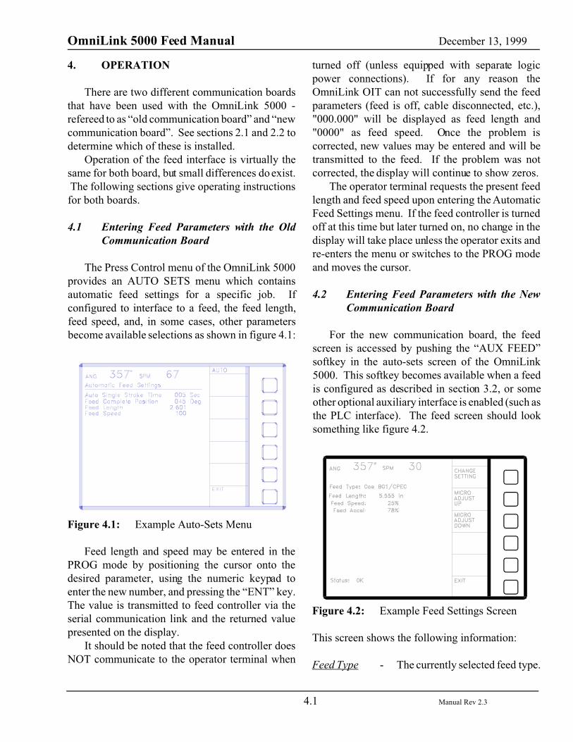
The Press Control menu of the OmniLink 5000provides an AUTO SETS menu which containsautomatic feed settings for a specific job. Ifconfigured to interface to a feed, the feed length,feed speed, and, in some cases, other parametersbecome available selections as shown in figure 4.1:
Figure 4.1: Example Auto-Sets Menu
Feed length and speed may be entered in thePROG mode by positioning the cursor onto thedesired parameter, using the numeric keypad toenter the new number, and pressing the “ENT” key.The value is transmitted to feed controller via theserial communication link and the returned valuepresented on the display.
It should be noted that the feed controller doesNOT communicate to the operator terminal when
turned off (unless equipped with separate logicpower connections). If for any reason theOmniLink OIT can not successfully send the feedparameters (feed is off, cable disconnected, etc.),"000.000" will be displayed as feed length and"0000" as feed speed. Once the problem iscorrected, new values may be entered and will betransmitted to the feed. If the problem was notcorrected, the display will continue to show zeros.
The operator terminal requests the present feedlength and feed speed upon entering the AutomaticFeed Settings menu. If the feed controller is turnedoff at this time but later turned on, no change in thedisplay will take place unless the operator exits andre-enters the menu or switches to the PROG modeand moves the cursor.
4.2 Entering Feed Parameters with the NewCommunication Board
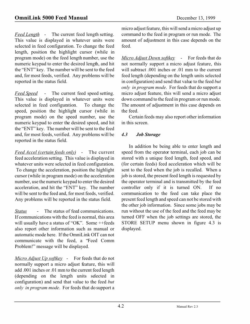
For the new communication board, the feedscreen is accessed by pushing the “AUX FEED”softkey in the auto-sets screen of the OmniLink5000. This softkey becomes available when a feedis configured as described in section 3.2, or someother optional auxiliary interface is enabled (such asthe PLC interface). The feed screen should looksomething like figure 4.2.
Figure 4.2: Example Feed Settings Screen
This screen shows the following information:
Feed Type - The currently selected feed type.
OmniLink 5000 Feed Manual December 13, 1999
4.2 Manual Rev 2.3
Feed Length - The current feed length setting.This value is displayed in whatever units wereselected in feed configuration. To change the feedlength, position the highlight cursor (while inprogram mode) on the feed length number, use thenumeric keypad to enter the desired length, and hitthe “ENT” key. The number will be sent to the feedand, for most feeds, verified. Any problems will bereported in the status field.
Feed Speed - The current feed speed setting.This value is displayed in whatever units wereselected in feed configuration. To change thespeed, position the highlight cursor (while inprogram mode) on the speed number, use thenumeric keypad to enter the desired speed, and hitthe “ENT” key. The number will be sent to the feedand, for most feeds, verified. Any problems will bereported in the status field.
Feed Accel (certain feeds only) - The currentfeed acceleration setting. This value is displayed inwhatever units were selected in feed configuration. To change the acceleration, position the highlightcursor (while in program mode) on the accelerationnumber, use the numeric keypad to enter the desiredacceleration, and hit the “ENT” key. The numberwill be sent to the feed and, for most feeds, verified.Any problems will be reported in the status field.
Status - The status of feed communications.If communications with the feed is normal, this areawill usually have a status of “OK”. Some ++feedsalso report other information such as manual orautomatic mode here. If the OmniLink OIT can notcommunicate with the feed, a “Feed CommProblem!” message will be displayed.
Micro Adjust Up softkey - For feeds that do notnormally support a micro adjust feature, this willadd .001 inches or .01 mm to the current feed length(depending on the length units selected inconfiguration) and send that value to the feed butonly in program mode. For feeds that do support a
micro adjust feature, this will send a micro adjust upcommand to the feed in program or run mode. Theamount of adjustment in this case depends on thefeed.
Micro Adjust Down softkey - For feeds that donot normally support a micro adjust feature, thiswill subtract .001 inches or .01 mm to the currentfeed length (depending on the length units selectedin configuration) and send that value to the feed butonly in program mode. For feeds that do support amicro adjust feature, this will send a micro adjustdown command to the feed in program or run mode.The amount of adjustment in this case depends onthe feed.
Certain feeds may also report other informationin this screen.
4.3 Job Storage
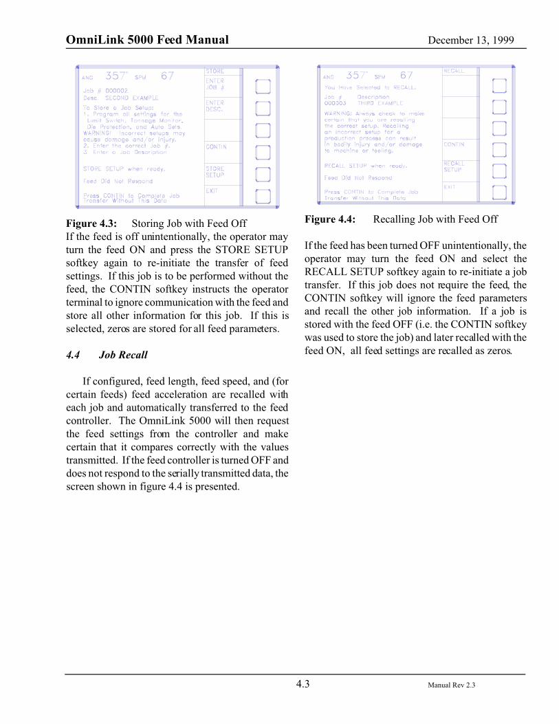
In addition be being able to enter length andspeed from the operator terminal, each job can bestored with a unique feed length, feed speed, and(for certain feeds) feed acceleration which will besent to the feed when the job is recalled. When ajob is stored, the present feed length is requested bythe operator terminal and is transmitted by the feedcontroller only if it is turned ON. If nocommunication to the feed can take place thepresent feed length and speed can not be stored withthe other job information. Since some jobs may berun without the use of the feed and the feed may beturned OFF when the job settings are stored, theSTORE SETUP menu shown in figure 4.3 isdisplayed.
OmniLink 5000 Feed Manual December 13, 1999
4.3 Manual Rev 2.3
Figure 4.3: Storing Job with Feed OffIf the feed is off unintentionally, the operator mayturn the feed ON and press the STORE SETUPsoftkey again to re-initiate the transfer of feedsettings. If this job is to be performed without thefeed, the CONTIN softkey instructs the operatorterminal to ignore communication with the feed andstore all other information for this job. If this isselected, zeros are stored for all feed parameters.
4.4 Job Recall
If configured, feed length, feed speed, and (forcertain feeds) feed acceleration are recalled witheach job and automatically transferred to the feedcontroller. The OmniLink 5000 will then requestthe feed settings from the controller and makecertain that it compares correctly with the valuestransmitted. If the feed controller is turned OFF anddoes not respond to the serially transmitted data, thescreen shown in figure 4.4 is presented.
Figure 4.4: Recalling Job with Feed Off
If the feed has been turned OFF unintentionally, theoperator may turn the feed ON and select theRECALL SETUP softkey again to re-initiate a jobtransfer. If this job does not require the feed, theCONTIN softkey will ignore the feed parametersand recall the other job information. If a job isstored with the feed OFF (i.e. the CONTIN softkeywas used to store the job) and later recalled with thefeed ON, all feed settings are recalled as zeros.
OmniLink 5000 Feed Manual December 13, 1999
5.1 Manual Rev 2.3
5. INTERFACING TO OTHER FEEDS OR DEVICES
In many cases a feed that is not currently supported may have a programmable basic module or othermeans of customization. You may also want to tie in a PLC or other controlling device that is handling anentire feed line. In these cases it makes sense to program the device to emulate (or “look like”) anotheralready supported feed. The simplest feed to emulate is the Electro-Craft IQ2000 series. The protocol isas follows:
Communications:
RS232, 9600 baud, no parity, 1 start bit, 1 stop bit, 8 data bits.
Conventions:
[CR] = Carriage return[LF] = Line Feed[S] = Space X = Digit (0-9)
To Request Length from the feed:
5000 Sends:
G1[CR]
Feed Returns:
G1[CR][LF]G1[S]=[S]XXXX.XXXX[CR][LF][CR][LF]PDM>
To Send Length to feed:
5000 Sends:
G1=XXX.XXX[CR]
Feed Returns:
G1=XXX.XXX[CR][LF]G1[S]=[S]XXXX.XXXX[CR][LF][CR][LF]PDM>

OmniLink 5000 Feed Manual December 13, 1999
5.2 Manual Rev 2.3
To Request Speed from the feed:
5000 Sends:
G2[CR]
Feed Returns:
G2[CR][LF]G2[S]=[S]XXXX.XXXX[CR][LF][CR][LF]PDM>
To Send Speed to feed:
5000 Sends:
G2=XXXX[CR]
Feed Returns:
G2=XXXX[CR][LF]G2[S]=[S]XXXX.XXXX[CR][LF][CR][LF]PDM>
For feed length the 5000 will send numbers from 000.000 to 999.999. For feed speed it will send 0000 to9999. The normal use of feed speed has been to treat it as percent of maximum speed. Note that you musttreat any number over 100 as 100 if you use this as a percentage. The 5000 will send the length in all casesas XXX.XXX and the speed as XXXX. For instance, a length of 3.23 will be sent as 0003.2300 and .23 willbe sent as 0000.2300. A speed of 5 will be sent as 0005 and 100 will be sent as 0100. This is not the casefor the feed. The feed will suppress leading zeros. For instance, 3.23 will be sent as 3.2300 and .23 will besent as 0.2300. Note that the end of each feed response is “PDM>”. This is the prompt that would bedisplayed on the feed terminal.
Important!: The first part of the response from the feed looks just like what the 5000 sent. That isbecause it was echoed back to the 5000 on a character by character basis. For instance, in the case of alength setting command, the 5000 sent “G” and before it would send “1" the feed echoed “G” back to it.Then it sent “1" and before it would send “=” the feed sent “1" back to it and so on. The rest of the responsefrom the feed to the 5000 occurs in one big block.
OmniLink 5000 Feed Manual December 13, 1999
5.3 Manual Rev 2.3
Examples of Length set:
Operator enters 3.255 for feed length.
5000 Sends:
G1=003.255[CR]
Feed Returns:
G1=003.255[CR][LF]G1[S]=[S]3.2550[CR][LF][CR][LF]PDM>
Operator enters .3 for feed length
5000 Sends:
G1=000.300[CR]
Feed Returns:
G1=000.300[CR][LF]G1[S]=[S]0.3000[CR][LF][CR][LF]PDM>
Examples of Speed set:
Operator enters 5 for feed speed
5000 Sends:
G2=0005[CR]
Feed Returns:
G2=0005[CR][LF]G2[S]=[S]5.0000[CR][LF][CR][LF]PDM>
Operator enters 100 for feed speed
5000 Sends:
G2=0100[CR]
Feed Returns:

OmniLink 5000 Feed Manual December 13, 1999
5.4 Manual Rev 2.3
G2=0100[CR][LF]G2[S]=[S]100.0000[CR][LF][CR][LF]PDM>

OmniLink 5000 Feed Manual December 13, 1999
A.1 Manual Rev 2.3
If the OIT software version is older thanversion 2.0, the OIT and motherboard softwareMUST both be changed at the same time.
Appendix A - Upgrading Link Equipment
Link equipment may sometimes need softwareupgrades to take advantage of new features. Thefollowing sections explain how to do software andhardware upgrades.
A.1 General Chip Changing Rules
Changing the software on Link equipment isaccomplished by swapping electronic chips calledEPROMS (called “chips” in the rest if this section).These chips are plugged into sockets on variouscircuit boards on the equipment and can usually beidentified by the label that gives the chip type andversion number. No special equipment is necessaryto change a chip but it is necessary to observe a fewprecautions and rules:
� Make sure that power to the system is OFFwhen changing chips. Failure to observe thisprecaution can result in damage to theequipment.
� Gently pry a chip from its socket using a smallblade screw driver (or chip remover ifavailable). Be sure to place the screw driverbetween the socket and the chip - Not betweenthe socket and the circuit board!
� When inserting a chip into its socket, make surethe notch on the end of the chip is aligned withthe notch in the socket. The unit will not workif the chip is inserted backwards and damage tothe chip may result.
� When inserting a chip into its socket, make surethat no pins are bent under the chip and that allpins are in the socket.
A.2 System 1100 Tonnage Monitor UpgradeProcedure
System 1100 OIT software versions 2.0 and upwill display the OIT software version and themotherboard software version for about 5 secondswhen the unit powers up. Older software will onlydisplay the OIT version at power-up - the channel 1& 2 dual channel card must be removed to check themotherboard software version.
A.2.1 System 1100 OIT Software UpgradeProcedure
� Review section A.1 for chip changing rules!
� Turn off the power to the System 1100.
� Open the front door of the System 1100enclosure.
� Using Figure A.1, locate the software chip onthe circuit board mounted to the System 1100enclosure door and remove it.
� Install the new software chip labeled 1100-OITin the socket. All software versions prior toV2.0 had different chips for 2 channel and 4channel tonnage monitors, but V2.0 or higherworks with both 2 and 4 channel OITs.
OmniLink 5000 Feed Manual December 13, 1999
A.2 Manual Rev 2.3
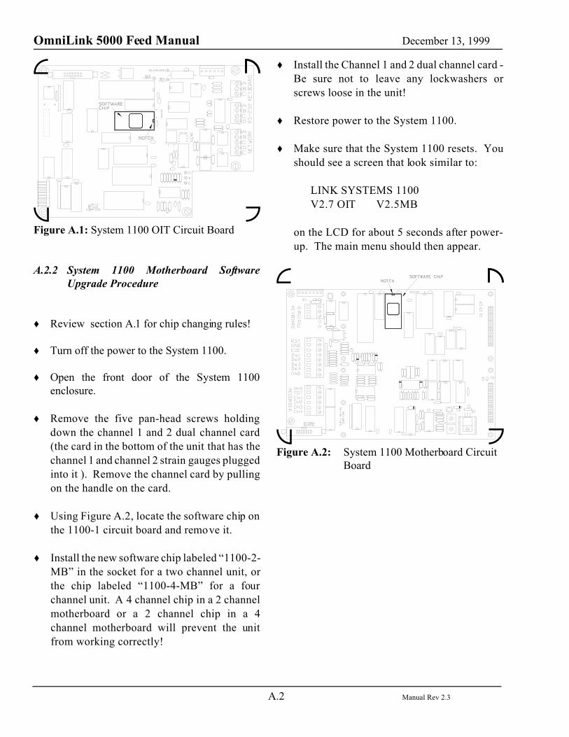
Figure A.1: System 1100 OIT Circuit Board
A.2.2 System 1100 Motherboard SoftwareUpgrade Procedure
� Review section A.1 for chip changing rules!
� Turn off the power to the System 1100.
� Open the front door of the System 1100enclosure.
� Remove the five pan-head screws holdingdown the channel 1 and 2 dual channel card(the card in the bottom of the unit that has thechannel 1 and channel 2 strain gauges pluggedinto it ). Remove the channel card by pullingon the handle on the card.
� Using Figure A.2, locate the software chip onthe 1100-1 circuit board and remove it.
� Install the new software chip labeled “1100-2-MB” in the socket for a two channel unit, orthe chip labeled “1100-4-MB” for a fourchannel unit. A 4 channel chip in a 2 channelmotherboard or a 2 channel chip in a 4channel motherboard will prevent the unitfrom working correctly!
� Install the Channel 1 and 2 dual channel card -Be sure not to leave any lockwashers orscrews loose in the unit!
� Restore power to the System 1100.
� Make sure that the System 1100 resets. Youshould see a screen that look similar to:
LINK SYSTEMS 1100V2.7 OIT V2.5MB
on the LCD for about 5 seconds after power-up. The main menu should then appear.
Figure A.2: System 1100 Motherboard CircuitBoard
OmniLink 5000 Feed Manual December 13, 1999
A.3 Manual Rev 2.3
A.3 OmniLink 5000 Upgrade Procedure
Most OmniLink 5000 press controls shippedprior to July 1998 will need to have a hardwareupgrade to work with LinkNet or to support certainfeeds. This upgrade consists of replacing the oldback plate and communications card on the operatorinterface terminal with a new back plate andcommunications card.
To determine which kind of communicationsboard is installed, look at the back of the OmniLinkoperator interface terminal (the box with the displayscreen on it - also called the OIT). There should be5 connectors on the back of the OIT if a newcommunications board is installed (see Figure A.3).If only 4 connectors are present, then an oldercommunications board is installed (see Figure A.4).
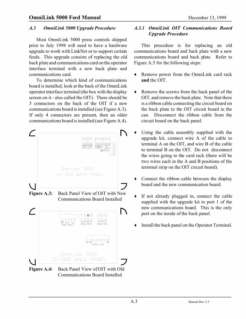
Figure A.3: Back Panel View of OIT with NewCommunications Board Installed
Figure A.4: Back Panel View of OIT with OldCommunications Board Installed
A.3.1 OmniLink OIT Communications BoardUpgrade Procedure
This procedure is for replacing an oldcommunications board and back plate with a newcommunications board and back plate. Refer toFigure A.5 for the following steps:
� Remove power from the OmniLink card rackand the OIT.
� Remove the screws from the back panel of theOIT, and remove the back plate. Note that thereis a ribbon cable connecting the circuit board onthe back plate to the OIT circuit board in thecan. Disconnect the ribbon cable from thecircuit board on the back panel.
� Using the cable assembly supplied with theupgrade kit, connect wire A of the cable toterminal A on the OIT, and wire B of the cableto terminal B on the OIT. Do not disconnectthe wires going to the card rack (there will betwo wires each in the A and B positions of theterminal strip on the OIT circuit board).
� Connect the ribbon cable between the displayboard and the new communication board.
� If not already plugged in, connect the cablesupplied with the upgrade kit to port 1 of thenew communications board. This is the onlyport on the inside of the back panel.
� Install the back panel on the Operator Terminal.
OmniLink 5000 Feed Manual December 13, 1999
A.4 Manual Rev 2.3
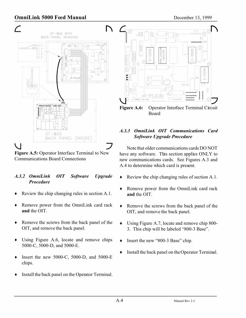
Figure A.5: Operator Interface Terminal to NewCommunications Board Connections
A.3.2 OmniLink OIT Software UpgradeProcedure
� Review the chip changing rules in section A.1.
� Remove power from the OmniLink card rackand the OIT.
� Remove the screws from the back panel of theOIT, and remove the back panel.
� Using Figure A.6, locate and remove chips5000-C, 5000-D, and 5000-E.
� Insert the new 5000-C, 5000-D, and 5000-Echips.
� Install the back panel on the Operator Terminal.
Figure A.6: Operator Interface Terminal CircuitBoard
A.3.3 OmniLink OIT Communications CardSoftware Upgrade Procedure
Note that older communications cards DO NOThave any software. This section applies ONLY tonew communications cards. See Figures A.3 andA.4 to determine which card is present.
� Review the chip changing rules of section A.1.
� Remove power from the OmniLink card rackand the OIT.
� Remove the screws from the back panel of theOIT, and remove the back panel.
� Using Figure A.7, locate and remove chip 800-3. This chip will be labeled “800-3 Base”.
� Insert the new “800-3 Base” chip.
� Install the back panel on the Operator Terminal.
OmniLink 5000 Feed Manual December 13, 1999
A.5 Manual Rev 2.3
Note that communications cards can have upto two additional software chips as options. Replace these chips only with chips thathave the same labeling (except for theversion)!
Figure A.7: Communications Circuit Board
A.3.4 OmniLink Logic Module UpgradeProcedure
The base card rack has only one card, the LogicModule, that contains software. To upgrade thelogic module:
� Review the chip changing rules of section A.1.
� Remove power from the OmniLink card rackand the OIT.
� Remove the logic board from the card rack.
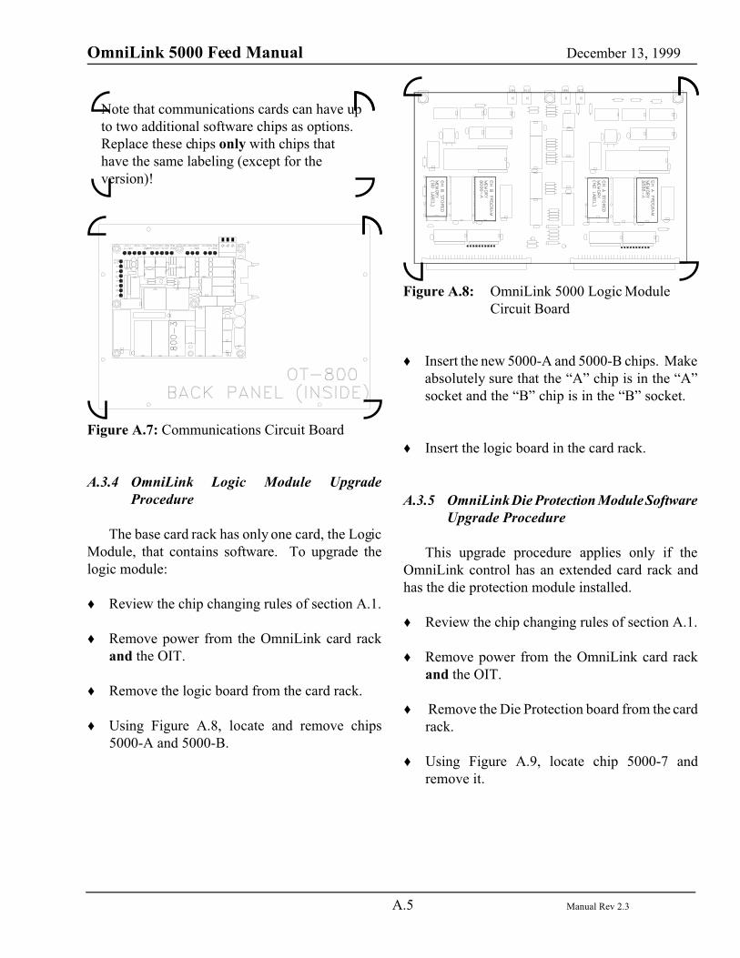
� Using Figure A.8, locate and remove chips5000-A and 5000-B.
Figure A.8: OmniLink 5000 Logic ModuleCircuit Board
� Insert the new 5000-A and 5000-B chips. Makeabsolutely sure that the “A” chip is in the “A”socket and the “B” chip is in the “B” socket.
� Insert the logic board in the card rack.
A.3.5 OmniLink Die Protection Module SoftwareUpgrade Procedure
This upgrade procedure applies only if theOmniLink control has an extended card rack andhas the die protection module installed.
� Review the chip changing rules of section A.1.
� Remove power from the OmniLink card rackand the OIT.
� Remove the Die Protection board from the cardrack.
� Using Figure A.9, locate chip 5000-7 andremove it.

OmniLink 5000 Feed Manual December 13, 1999
A.6 Manual Rev 2.3
Figure A.9: OmniLink 5000 Die ProtectionModule Circuit Board
� Insert the new 5000-7 chip.
� Insert the Die Protection board in the card rack.
A.3.6 OmniLink Tonnage Monitor ModuleSoftware Upgrade Procedure
This upgrade procedure applies only if theOmniLink control has an extended card rack andhas the tonnage monitor module installed.
� Review the chip changing rules of section A.1.
� Remove power from the OmniLink card rackand the OIT.
� Remove the Tonnage Monitor Module from thecard rack.
� Using Figure A.10, locate and remove the 5000-8 chip.
Figure A.10: OmniLink Tonnage MonitorModule Circuit Board
� Insert the new 5000-8 chip.
� Insert the Tonnage Monitor Module in the cardrack.
A.3.7 OmniLink Auto-Setup Module SoftwareUpgrade Procedure
This upgrade procedure applies only if theOmniLink control has an extended card rack andhas the auto-setup module installed.
� Review the chip changing rules of section A.1.
� Remove power from the OmniLink card rackand the OIT.
� Remove the Auto-Setup board from the cardrack.
� Remove the module (if present) installed in theSS1 position.
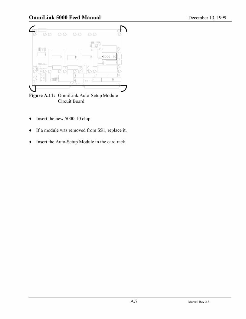
� Using Figure A.11, locate and remove the 5000-10 chip.
OmniLink 5000 Feed Manual December 13, 1999
A.7 Manual Rev 2.3
Figure A.11: OmniLink Auto-Setup ModuleCircuit Board
� Insert the new 5000-10 chip.
� If a module was removed from SS1, replace it.
� Insert the Auto-Setup Module in the card rack.


![Autdev Interface [Autorship + Webdevelopment + Interface]](https://static.fdocuments.in/doc/165x107/568bd8ee1a28ab2034a52641/autdev-interface-autorship-webdevelopment-interface.jpg)