SYSMAC C200HW-PCU01 C200HW-PCS01-V2 PC Card Unit
236
SYSMAC C200HW-PCU01 C200HW-PCS01-V2 PC Card Unit Operation Manual Produced February 2001
Transcript of SYSMAC C200HW-PCU01 C200HW-PCS01-V2 PC Card Unit

SYSMAC C200HW-PCU01C200HW-PCS01-V2PC Card Unit
Operation Manual
Produced February 2001

!
!
!
v
Notice:OMRON products are manufactured for use according to proper procedures by a qualified operatorand only for the purposes described in this manual.
The following conventions are used to indicate and classify precautions in this manual. Always heedthe information provided with them. Failure to heed precautions can result in injury to people or dam-age to the product.
DANGER Indicates an imminently hazardous situation which, if not avoided, will result in death orserious injury.
WARNING Indicates a potentially hazardous situation which, if not avoided, could result in death orserious injury.
Caution Indicates a potentially hazardous situation which, if not avoided, may result in minor ormoderate injury, or property damage.
OMRON Product ReferencesAll OMRON products are capitalized in this manual. The word “Unit” is also capitalized when it refersto an OMRON product, regardless of whether or not it appears in the proper name of the product.
The abbreviation “Ch,” which appears in some displays and on some OMRON products, often means“word” and is abbreviated “Wd” in documentation in this sense.
The abbreviation “PC” means Programmable Controller and is not used as an abbreviation for any-thing else.
MS-DOS is a registered trademark of Microsoft Corporation.
PC-DOS is a registered trademark of International Business Machines Corporation.
PCM Plus is a registered trademark of Phoenix Technologies, Ltd.
In general, system names and product names mentioned in this manual are registered trademarks ofthe respective developers or manufacturers.
Visual AidsThe following headings appear in the left column of the manual to help you locate different types ofinformation.
Note Indicates information of particular interest for efficient and convenient operationof the product.
1, 2, 3... 1. Indicates lists of one sort or another, such as procedures, checklists, etc.
OMRON, 2001All rights reserved. No part of this publication may be reproduced, stored in a retrieval system, or transmitted, in anyform, or by any means, mechanical, electronic, photocopying, recording, or otherwise, without the prior written permis-sion of OMRON.
No patent liability is assumed with respect to the use of the information contained herein. Moreover, because OMRON isconstantly striving to improve its high-quality products, the information contained in this manual is subject to changewithout notice. Every precaution has been taken in the preparation of this manual. Nevertheless, OMRON assumes noresponsibility for errors or omissions. Neither is any liability assumed for damages resulting from the use of the informa-tion contained in this publication.

TABLE OF CONTENTS
vii
PRECAUTIONS xiii. . . . . . . . . . . . . . . . . . . . . . . . . . . . . . . . . 1 Intended Audience xiv. . . . . . . . . . . . . . . . . . . . . . . . . . . . . . . . . . . . . . . . . . . . . . . . . . . . . . . . . . . 2 General Precautions xiv. . . . . . . . . . . . . . . . . . . . . . . . . . . . . . . . . . . . . . . . . . . . . . . . . . . . . . . . . . 3 Safety Precautions xiv. . . . . . . . . . . . . . . . . . . . . . . . . . . . . . . . . . . . . . . . . . . . . . . . . . . . . . . . . . . 4 Operating Environment Precautions xiv. . . . . . . . . . . . . . . . . . . . . . . . . . . . . . . . . . . . . . . . . . . . . 5 Application Precautions xv. . . . . . . . . . . . . . . . . . . . . . . . . . . . . . . . . . . . . . . . . . . . . . . . . . . . . . 6 EC Directives xvi. . . . . . . . . . . . . . . . . . . . . . . . . . . . . . . . . . . . . . . . . . . . . . . . . . . . . . . . . . . . . .
PART 1: FEATURES AND COMPONENTS 1. . . . SECTION 1Features and System Configuration 3. . . . . . . . . . . . . . . . .
1-1 Features 4. . . . . . . . . . . . . . . . . . . . . . . . . . . . . . . . . . . . . . . . . . . . . . . . . . . . . . . . . . . . . . . 1-2 System Configuration 5. . . . . . . . . . . . . . . . . . . . . . . . . . . . . . . . . . . . . . . . . . . . . . . . . . . . . 1-3 PC Card Unit Basics 6. . . . . . . . . . . . . . . . . . . . . . . . . . . . . . . . . . . . . . . . . . . . . . . . . . . . . .
SECTION 2Components 9. . . . . . . . . . . . . . . . . . . . . . . . . . . . . . . . . . . .
2-1 C200HW-PCU01 PC Card Unit 10. . . . . . . . . . . . . . . . . . . . . . . . . . . . . . . . . . . . . . . . . . . . . 2-2 C200HW-PCS01-V2 Ethernet Set 12. . . . . . . . . . . . . . . . . . . . . . . . . . . . . . . . . . . . . . . . . . . 2-3 C200HW-CE011/CE012 Bus Connection Unit 13. . . . . . . . . . . . . . . . . . . . . . . . . . . . . . . . . 2-4 Other Required Peripheral Devices 15. . . . . . . . . . . . . . . . . . . . . . . . . . . . . . . . . . . . . . . . . .
PART 2: INSTALLATION AND OPERATION 19. . SECTION 3Preparations for Operation 21. . . . . . . . . . . . . . . . . . . . . . . .
3-1 Outline 22. . . . . . . . . . . . . . . . . . . . . . . . . . . . . . . . . . . . . . . . . . . . . . . . . . . . . . . . . . . . . . . . 3-2 Procedures 22. . . . . . . . . . . . . . . . . . . . . . . . . . . . . . . . . . . . . . . . . . . . . . . . . . . . . . . . . . . . .
SECTION 4Installation and Switch Settings 25. . . . . . . . . . . . . . . . . . . .
4-1 Before Installing a PC Card Unit 26. . . . . . . . . . . . . . . . . . . . . . . . . . . . . . . . . . . . . . . . . . . . 4-2 Component Names and Functions 29. . . . . . . . . . . . . . . . . . . . . . . . . . . . . . . . . . . . . . . . . . . 4-3 Setting the System Switch 31. . . . . . . . . . . . . . . . . . . . . . . . . . . . . . . . . . . . . . . . . . . . . . . . . 4-4 Mounting the PC Card Unit 35. . . . . . . . . . . . . . . . . . . . . . . . . . . . . . . . . . . . . . . . . . . . . . . . 4-5 Installing the Bus Connection Unit 38. . . . . . . . . . . . . . . . . . . . . . . . . . . . . . . . . . . . . . . . . . 4-6 Installing and Removing Memory Cards 42. . . . . . . . . . . . . . . . . . . . . . . . . . . . . . . . . . . . . . 4-7 Starting the PC Card Unit 44. . . . . . . . . . . . . . . . . . . . . . . . . . . . . . . . . . . . . . . . . . . . . . . . .
SECTION 5Using Memory Cards 47. . . . . . . . . . . . . . . . . . . . . . . . . . . . .
5-1 Outline 48. . . . . . . . . . . . . . . . . . . . . . . . . . . . . . . . . . . . . . . . . . . . . . . . . . . . . . . . . . . . . . . . 5-2 Formatting Memory Cards 49. . . . . . . . . . . . . . . . . . . . . . . . . . . . . . . . . . . . . . . . . . . . . . . . . 5-3 File Operations: CMCR Instruction 51. . . . . . . . . . . . . . . . . . . . . . . . . . . . . . . . . . . . . . . . . . 5-4 Memory Card Access Times for CMCR Instructions 62. . . . . . . . . . . . . . . . . . . . . . . . . . . . 5-5 Sample Program 63. . . . . . . . . . . . . . . . . . . . . . . . . . . . . . . . . . . . . . . . . . . . . . . . . . . . . . . . . 5-6 Debugging Ladder Programs 64. . . . . . . . . . . . . . . . . . . . . . . . . . . . . . . . . . . . . . . . . . . . . . .
PART 3: USING ETHERNET 67. . . . . . . . . . . . . . . . SECTION 6Preparations for Operation 69. . . . . . . . . . . . . . . . . . . . . . . .
6-1 Outline 70. . . . . . . . . . . . . . . . . . . . . . . . . . . . . . . . . . . . . . . . . . . . . . . . . . . . . . . . . . . . . . . . 6-2 Procedures 70. . . . . . . . . . . . . . . . . . . . . . . . . . . . . . . . . . . . . . . . . . . . . . . . . . . . . . . . . . . . . 6-3 Communications 72. . . . . . . . . . . . . . . . . . . . . . . . . . . . . . . . . . . . . . . . . . . . . . . . . . . . . . . . .

TABLE OF CONTENTS
viii
SECTION 7Setting Up Ethernet 75. . . . . . . . . . . . . . . . . . . . . . . . . . . . . .
7-1 Preparations 76. . . . . . . . . . . . . . . . . . . . . . . . . . . . . . . . . . . . . . . . . . . . . . . . . . . . . . . . . . . . 7-2 Installing and Removing the Ethernet Card 76. . . . . . . . . . . . . . . . . . . . . . . . . . . . . . . . . . . . 7-3 Connecting to the Ethernet Network 81. . . . . . . . . . . . . . . . . . . . . . . . . . . . . . . . . . . . . . . . . 7-4 Connecting to the Personal Computer 82. . . . . . . . . . . . . . . . . . . . . . . . . . . . . . . . . . . . . . . . 7-5 Setting Up the Ethernet Environment 84. . . . . . . . . . . . . . . . . . . . . . . . . . . . . . . . . . . . . . . . 7-6 Setup Software Operation 88. . . . . . . . . . . . . . . . . . . . . . . . . . . . . . . . . . . . . . . . . . . . . . . . . 7-7 Backing Up and Restoring Settings 100. . . . . . . . . . . . . . . . . . . . . . . . . . . . . . . . . . . . . . . . . .
SECTION 8Using SEND(90) and RECV(98) 105. . . . . . . . . . . . . . . . . . . .
8-1 Outline 106. . . . . . . . . . . . . . . . . . . . . . . . . . . . . . . . . . . . . . . . . . . . . . . . . . . . . . . . . . . . . . . . 8-2 SEND(90) 109. . . . . . . . . . . . . . . . . . . . . . . . . . . . . . . . . . . . . . . . . . . . . . . . . . . . . . . . . . . . . . 8-3 RECV(98) 111. . . . . . . . . . . . . . . . . . . . . . . . . . . . . . . . . . . . . . . . . . . . . . . . . . . . . . . . . . . . . . 8-4 Minimum Transmission Delay Time for SEND/RECV Instructions 113. . . . . . . . . . . . . . . .
SECTION 9FINS Commands 115. . . . . . . . . . . . . . . . . . . . . . . . . . . . . . . .
9-1 FINS Communications Service 116. . . . . . . . . . . . . . . . . . . . . . . . . . . . . . . . . . . . . . . . . . . . . 9-2 Using FINS Communications 117. . . . . . . . . . . . . . . . . . . . . . . . . . . . . . . . . . . . . . . . . . . . . . 9-3 Using the CMCR Instruction 119. . . . . . . . . . . . . . . . . . . . . . . . . . . . . . . . . . . . . . . . . . . . . . . 9-4 Using FINS Commands and Responses 124. . . . . . . . . . . . . . . . . . . . . . . . . . . . . . . . . . . . . . . 9-5 Sample Program 128. . . . . . . . . . . . . . . . . . . . . . . . . . . . . . . . . . . . . . . . . . . . . . . . . . . . . . . . . 9-6 FINS Communications From Computers 129. . . . . . . . . . . . . . . . . . . . . . . . . . . . . . . . . . . . . .
SECTION 10Socket Services 133. . . . . . . . . . . . . . . . . . . . . . . . . . . . . . . . . .
10-1 About Socket Services 134. . . . . . . . . . . . . . . . . . . . . . . . . . . . . . . . . . . . . . . . . . . . . . . . . . . . 10-2 Using Socket Services 138. . . . . . . . . . . . . . . . . . . . . . . . . . . . . . . . . . . . . . . . . . . . . . . . . . . . 10-3 Sample Programs for TCP and UDP Communications 146. . . . . . . . . . . . . . . . . . . . . . . . . . .
SECTION 11Using FINS Commands and Responses 163. . . . . . . . . . . . . .
11-1 Commands and Responses for C200HX/HG/HE CPUs 164. . . . . . . . . . . . . . . . . . . . . . . . . . 11-2 PC Card Unit Commands and Responses 176. . . . . . . . . . . . . . . . . . . . . . . . . . . . . . . . . . . . . 11-3 FINS Commands Requesting Socket Services 185. . . . . . . . . . . . . . . . . . . . . . . . . . . . . . . . .
PART 4: TROUBLESHOOTING 197. . . . . . . . . . . . .
SECTION 12Error Processing 199. . . . . . . . . . . . . . . . . . . . . . . . . . . . . . . .
12-1 Indicators and the Error Log 200. . . . . . . . . . . . . . . . . . . . . . . . . . . . . . . . . . . . . . . . . . . . . . . 12-2 Troubleshooting 201. . . . . . . . . . . . . . . . . . . . . . . . . . . . . . . . . . . . . . . . . . . . . . . . . . . . . . . . . 12-3 Echo Test With PING Command 201. . . . . . . . . . . . . . . . . . . . . . . . . . . . . . . . . . . . . . . . . . . .

TABLE OF CONTENTS
ix
AppendicesA Standard Models 203. . . . . . . . . . . . . . . . . . . . . . . . . . . . . . . . . . . . . . . . . . . . . . . . . . . . . . . . . . . B Specifications 205. . . . . . . . . . . . . . . . . . . . . . . . . . . . . . . . . . . . . . . . . . . . . . . . . . . . . . . . . . . . . . C Connector Pin Assignments 207. . . . . . . . . . . . . . . . . . . . . . . . . . . . . . . . . . . . . . . . . . . . . . . . . . . D Response Codes from the C200HX/HG/HE CPU 209. . . . . . . . . . . . . . . . . . . . . . . . . . . . . . . . . . E FINS Response Codes from the PC Card Unit 215. . . . . . . . . . . . . . . . . . . . . . . . . . . . . . . . . . . . F Differences with the CV-series or CS1-series Ethernet Units 217. . . . . . . . . . . . . . . . . . . . . . . . . G Example Using a Memory Card with a Personal Computer 219. . . . . . . . . . . . . . . . . . . . . . . . . . H Precautions when Setting Up the Network 221. . . . . . . . . . . . . . . . . . . . . . . . . . . . . . . . . . . . . . . I Contents of Version Upgrade 223. . . . . . . . . . . . . . . . . . . . . . . . . . . . . . . . . . . . . . . . . . . . . . . . . . J Remote Tool Connection Procedure 225. . . . . . . . . . . . . . . . . . . . . . . . . . . . . . . . . . . . . . . . . . . .
Glossary 227. . . . . . . . . . . . . . . . . . . . . . . . . . . . . . . . . . . . . . .
Index 239. . . . . . . . . . . . . . . . . . . . . . . . . . . . . . . . . . . . . . . . . . Revision History 243. . . . . . . . . . . . . . . . . . . . . . . . . . . . . . . . .

xi
About this Manual:
This manual describes the installation and operation of the PC Card Unit and includes the sectionsdescribed below. A PC Card Unit enables usage of a PC card with a C200HX/HG/HE PC to provide aninterface to extra memory or an Ethernet connection.
In this manual Programmable Controller has been abbreviated as PC. Do not confuse this with personalcomputer, which has not been abbreviated except in the case of the PC Card Unit.
Please read this manual carefully and be sure you understand the information provided before attemptingto install and operate a PC Card Units. Be sure to read the following section before operating the PCCard Unit.
Section 1 explains the features and system configuration of the PC Card Unit.
Section 2 outlines the individual system components and their functions. Devices that can be purchasedseparately are also described.
Section 3 outlines the installation of a PC Card Unit and peripheral devices.
Section 4 describes how to install a PC Card Unit and set up the C200HX/HG/HE.
Section 5 describes formatting Memory Cards, the file format, and file transfers between a PC Card Unitand the C200HX/HG/HE.
Section 6 outlines the installation of a PC Card Unit and connection to Ethernet.
Section 7 describes how to install Ethernet Cards and use the setup software.
Section 8 explains how to use SEND and RECV commands to transfer data.
Section 9 provides information on communicating in Ethernet Systems using FINS commands, andexplains how to use the CMCR instruction to issue FINS commands.
Section 10 describes sockets (an interface for directly using TCP and UDP functions from the user pro-gram) and explains how to use socket services.
Section 11 describes the FINS commands that can be sent to the C200HX/HG/HE CPU and the FINScommands that can be sent to the PC Card Unit.
Section 12 provides explanations of each indicator and the actions to be taken for them, and explains howto use the error log.
The Appendices provide information on standard models, specifications, connector pin assignments,response codes from the C200HX/HG/HE CPU, FINS response codes from the PC Card Unit, differenceswith the CV-series Ethernet Unit, an example using a memory card with a personal computer, precautionsfor setting up the network, contents of version upgrade (PCS01-E to PCS01-EV1), and remote tool con-nection procedure.
WARNING Failure to read and understand the information provided in this manual may result inpersonal injury or death, damage to the product, or product failure. Please read eachsection in its entirety and be sure you understand the information provided in the sectionand related sections before attempting any of the procedures or operations given.
!

xiii
PRECAUTIONS
This section provides general precautions for using the Programmable Controller (PC) and related devices.
The information contained in this section is important for the safe and reliable application of the PC. You must readthis section and understand the information contained before attempting to set up or operate a PC system.
1 Intended Audience xiv. . . . . . . . . . . . . . . . . . . . . . . . . . . . . . . . . . . . . . . . . . . . . . . . . . . . . . . . . . . . 2 General Precautions xiv. . . . . . . . . . . . . . . . . . . . . . . . . . . . . . . . . . . . . . . . . . . . . . . . . . . . . . . . . . . 3 Safety Precautions xiv. . . . . . . . . . . . . . . . . . . . . . . . . . . . . . . . . . . . . . . . . . . . . . . . . . . . . . . . . . . . 4 Operating Environment Precautions xiv. . . . . . . . . . . . . . . . . . . . . . . . . . . . . . . . . . . . . . . . . . . . . . 5 Application Precautions xv. . . . . . . . . . . . . . . . . . . . . . . . . . . . . . . . . . . . . . . . . . . . . . . . . . . . . . . . 6 EC Directives xvi. . . . . . . . . . . . . . . . . . . . . . . . . . . . . . . . . . . . . . . . . . . . . . . . . . . . . . . . . . . . . . . .

!
!
!
xiv
1 Intended AudienceThis manual is intended for the following personnel, who must also have knowl-edge of electrical systems (an electrical engineer or the equivalent).
• Personnel in charge of installing FA systems.
• Personnel in charge of designing FA systems.
• Personnel in charge of managing FA systems and facilities.
2 General PrecautionsThe user must operate the product according to the performance specificationsdescribed in the operation manuals.
Before using the product under conditions which are not described in the manualor applying the product to nuclear control systems, railroad systems, aviationsystems, vehicles, combustion systems, medical equipment, amusementmachines, safety equipment, and other systems, machines, and equipment thatmay have a serious influence on lives and property if used improperly, consultyour OMRON representative.
Make sure that the ratings and performance characteristics of the product aresufficient for the systems, machines, and equipment, and be sure to provide thesystems, machines, and equipment with double safety mechanisms.
This manual provides information for programming and operating OMRON PCs.Be sure to read this manual before attempting to use the software and keep thismanual close at hand for reference during operation.
WARNING It is extremely important that a PC and all PC Units be used for the specifiedpurpose and under the specified conditions, especially in applications that candirectly or indirectly affect human life. You must consult with your OMRONrepresentative before applying a PC System to the abovementionedapplications.
3 Safety Precautions
WARNING Never attempt to disassemble any Units while power is being supplied. Doing somay result in serious electrical shock or electrocution.
WARNING Never touch any of the terminals while power is being supplied. Doing so mayresult in serious electrical shock or electrocution.
4 Operating Environment PrecautionsDo not operate the control system in the following places.
• Where the PC is exposed to direct sunlight.
• Where the ambient temperature is below 0°C or over 55°C.
• Where the PC may be affected by condensation due to radical temperaturechanges.
• Where the ambient humidity is below 10% or over 90%.
• Where there is any corrosive or inflammable gas.
• Where there is excessive dust, saline air, or metal powder.
• Where the PC is affected by vibration or shock.
• Where any water, oil, or chemical may splash on the PC.
Operating Environment Precautions 4

!
!
!
xv
• Provide proper shielding when installing in the following locations:
• Locations subject to static electricity or other sources of noise.
• Locations subject to strong electromagnetic fields.
• Locations subject to possible exposure to radiation.
• Locations near to power supply lines.
Caution The operating environment of the PC System can have a large effect on the lon-gevity and reliability of the system. Improper operating environments can lead tomalfunction, failure, and other unforeseeable problems with the PC System. Besure that the operating environment is within the specified conditions at installa-tion and remains within the specified conditions during the life of the system.
5 Application PrecautionsObserve the following precautions when using the PC.
WARNING Failure to abide by the following precautions could lead to serious or possiblyfatal injury. Always heed these precautions.
• Always ground the system to 100 Ω or less when installing the system to pro-tect against electrical shock.
• Always turn off the power supply to the PC before attempting any of the follow-ing. Performing any of the following with the power supply turned on may leadto electrical shock:
• Mounting or removing any Units (e.g., I/O Units, CPU Unit, etc.) or memorycassettes.
• Assembling any devices or racks.
• Connecting or disconnecting any cables or wiring.
Caution Failure to abide by the following precautions could lead to faulty operation or thePC or the system or could damage the PC or PC Units. Always heed these pre-cautions.
• Use the Units only with the power supplies and voltages specified in the opera-tion manuals. Other power supplies and voltages may damage the Units.
• Take measures to stabilize the power supply to conform to the rated supply if itis not stable.
• Provide circuit breakers and other safety measures to provide protectionagainst shorts in external wiring.
• Do not apply voltages exceeding the rated input voltage to Input Units. TheInput Units may be destroyed.
• Do not apply voltages exceeding the maximum switching capacity to OutputUnits. The Output Units may be destroyed.
• Always disconnect the LG terminal when performing withstand voltage tests.
• Install all Units according to instructions in the operation manuals. Improperinstallation may cause faulty operation.
• Be sure to tighten Backplane screws, terminal screws, and cable connectorscrews securely.
• Do not attempt to take any Units apart, to repair any Units, or to modify anyUnits in any way.
• Be sure to have this stickers in place on the Units when wiring. Wiring withoutthe stickers in place may result in wiring cuttings entering the Unit and causingfaulty operation.
Application Precautions 5

!
!
xvi
• Remove the stickers after the completion of wiring to ensure proper heat dis-sipation. Operating the Unit with the sticker in place may cause heat build-upand possible faulty operation.
• Use crimp terminals for wiring. Wiring bare wires directly to terminals mayresult in a fire.
• Be sure that terminal blocks and connectors are correct before connectingthem. Improper connection may damage the Units.
• Do not use the setup software for the C200HW-PCS01(-EV1) to perform set-tings for the C200HW-PCS01-V2.
Caution The following precautions are necessary to ensure the general safety of the sys-tem. Always heed these precautions.
• Provide double safety mechanisms to handle incorrect signals that can begenerated by broken signal lines or momentary power interruptions.
• Provide external interlock circuits, limit circuits, and other safety circuits inaddition to any provided within the PC to ensure safety.
Caution When using the PC Card, be sure to observe the following precautions.
• Insert or eject the PC Card for at least 10 seconds after it is inserted or ejected.(That is, don’t eject the PC Card for at least 10 seconds after it is inserted anddon’t insert the the PC Card for at least 10 seconds after it is ejected.)
• Don’t eject the PC Card while it is being accessed (while either the CARD1indicator or CARD2 indicator is lit).
6 EC DirectivesPC Card Units that meet EC directives must be installed as follows:
1, 2, 3... 1. PC Card Units are defined for installation inside control panels, so they mustall be installed within control panels. In addition, the control panels must begrounded, enclosed metal housings.
2. Used reinforced insulation or double insulation for the DC power suppliesused for the communications power supply, internal circuit power supply,and the I/O power supplies.
3. PC Card Units that meet EC directives also meet the common emissionstandard (EN50081-2). When PC Card Units are built into equipment, how-ever, the measure necessary to ensure that the standard is met will vary withthe overall configuration of the control panel, the other devices connected tothe control panel, and other conditions. You must therefore confirm that ECdirectives are met for the overall machine or device.
To reduce noise, wire the control panel with as thick and short electric lines aspossible and ground to 100 Ω min.
EC Directives 6

1
Part 1Features and Components
This part of the manual introduces the PC Card Unit’s features, describesthe components of the PC Card Unit, and explains the systemconfiguration.

3
SECTION 1Features and System Configuration
This section provides an introduction to the PC Card Unit’s features and explains the system configuration.
1-1 Features 4. . . . . . . . . . . . . . . . . . . . . . . . . . . . . . . . . . . . . . . . . . . . . . . . . . . . . . . . . . . . . . . . 1-2 System Configuration 5. . . . . . . . . . . . . . . . . . . . . . . . . . . . . . . . . . . . . . . . . . . . . . . . . . . . . . 1-3 PC Card Unit Basics 6. . . . . . . . . . . . . . . . . . . . . . . . . . . . . . . . . . . . . . . . . . . . . . . . . . . . . . .
1-3-1 Functions 6. . . . . . . . . . . . . . . . . . . . . . . . . . . . . . . . . . . . . . . . . . . . . . . . . . . . . . . . 1-3-2 Memory Card Functions 7. . . . . . . . . . . . . . . . . . . . . . . . . . . . . . . . . . . . . . . . . . . . 1-3-3 Ethernet Communication Functions 7. . . . . . . . . . . . . . . . . . . . . . . . . . . . . . . . . . .

4
1-1 FeaturesThe PC Card Unit provides various functions for using PC cards with SYSMACC200HX/HG/HE Programmable Controllers. CIO, DM, and EM data (but not theuser program) can be loaded and saved between C200HX/HG/HE Program-mable Controllers and memory cards inserted in the PC Card Unit. These opera-tions can be executed from ladder programs.
Inserting a commercially available Ethernet card into the PC Card Unit allowsreading from and writing to C200HX/HG/HE memory from a personal computeror workstation, including reading programs. (The program data that is read,however, cannot be edited with the Ladder Support Software.)
The PC Card Unit provides the following features.
Standard Memory Cards The PC Card Unit provides two PCMCIA 2.1-conforming PC card interface slots(but 3.3V cards are not supported). Either two type-I or -II or one type-III PC cardcan be installed. SRAM cards, FLASH cards, and ATA interface cards can all beused.
PC card data written by the PC Card Unit can be read and edited by commer-cially available personal computers, which can also be used to write data to thePC card.
File Operations C200HX/HG/HE memory contents can be written to memory cards as files,using ladder-diagram instructions. File contents can be compared withC200HX/HG/HE memory and files can be searched. Word data can be sepa-rated by commas in the file format, so commercially available spreadsheets canbe used.
Ethernet Expansion With the C200HW-PCS01-V2 PC Card Unit Ethernet Set, commercially avail-able Ethernet cards can be used to exchange data with CV Ethernet Units, per-sonal computers, workstations, etc., by using the FINS protocol via UDP/IP.
FINS protocol is a communications protocol developed by OMRON for FA. Fordetails, refer to Section 11 Using FINS Commands and Responses.
Note The PC Card Unit cannot be used with the C200HE-CPU11-E.
Personal ComputerCompatibility
Features Section 1-1

5
1-2 System ConfigurationSystems using the PC Card Unit can be configured in either of two ways. Thefirst is to use the C200HW-PCU01, which is the basic system for using PC cards.The second is to use the C200HW-PCS01-V2 PC Card Unit Ethernet Set, whichallows you to add Ethernet functionality to the basic system.
Basic System Configuration (C200HW-PCU01)
C200HW-PCU01 PC Card Unit
C200HX/HG/HE
C200HW-CE011 Bus Connection Unit
Memory
Personal computer
card (SRAM, FLASH, ATA)
System Configuration Section 1-2

6
Ethernet System Configuration (C200HW-PCS01-V2)
C200HW-PCS01-V2 PC Card Unit Ethernet Set
C200HX/HG/HE
C200HW-CE011 Bus Connection Unit
Ethernet Card
Personal computer
Hub
Ethernet Unit
Note A MAU (Media Attachment Unit) is required to connect twisted-pair cable to aCV-series Ethernet Unit.
1-3 PC Card Unit BasicsThis section provides a basic introduction to the PC Card Unit.
1-3-1 FunctionsThe PC Card Unit has both memory card functions and Ethernet communica-tions functions, as shown in the following diagram.
PC Card Unit functions
Memory card functions
Ethernet communicationfunctions
File writing
File reading
File and memory comparison
File searching
SEND(90) and RECV(98)
FINS communications service
Socket service
The various services that can be performed using the memory card and Ether-net communications functions are described on the following pages.
PC Card Unit Basics Section 1-3

7
1-3-2 Memory Card FunctionsWhen the memory card functions are used, the following four operations can beexecuted with respect to memory cards.
Card Macro commandPC Card Unit
Bus ConnectionUnit
Memory card
1. File WriteWrites contents of CIO, DM, EM, etc.,to the memory card as files.
2. File ReadReads file data from memory card to CIO,DM, EM, etc.
3. File and Memory CompareCompares contents of CIO, DM, EM, etc.,to contents of files on memory card.
4. File SearchSearches data in files onmemory card.
Note Read and write operations for the ladder program cannot be executed.
1-3-3 Ethernet Communication FunctionsThe C200HW-PCS01-V2 PC Card Unit Ethernet Set supports three commu-nications methods. For details regarding Ethernet communications setup andmethods, refer to Section 6 Preparations for Operation onwards.
Communications Using SEND(90) and RECV(98)
SEND(90)/RECV(98)
Bus ConnectionUnit
PC Card Unit
Ethernet Card
SEND(90)/RECV(98)
FA Computer
PC Card Unit Basics Section 1-3

8
Data communications can be carried out by means of SEND(90) and RECV(98).The data to be sent or received must be set, but the communications processingis automatically performed internally. For details, refer to Section 8 UsingSEND(90) and RECV(98).
FINS Communications Service (FINS Command/Response)
Bus ConnectionUnit
PC Card Unit
Ethernet Card
FINS Command Response
FA Computer
CMCR
When PC Card Unit Receives a FINS CommandWhen the PC Card Unit receives a command, it automatically interprets thecommand and sends a response. All of the processing is performed automati-cally, so there is no need to create a user program at the Programmable Control-ler. For details, refer to Section 9 FINS Commands.When a FINS Command is Sent From the PC Card UnitA FINS command is issued using the CMCR instruction, and a response isreturned from the recipient of the command. That response is returned automat-ically if the recipient of the FINS command is a C200HX/HG/HE or CVM1/CVProgrammable Controller. For details, refer to Section 9 FINS Commands.FINS Communications Between a Computer and a PC Card UnitTo use FINS commands from a computer, create the command data in the pro-gram at the computer according to the FINS command format. Have the FINSresponses that are returned form the PC Card Unit analyzed and processedaccording to that format. For details, refer to Section 9 FINS Commands.
Socket Services
Bus ConnectionUnit
PC Card Unit
Ethernet Card
Communications by UDP, TCP
UNIX workstation FA Computer
CMCR
A socket is an interface which allows a user program to directly use TCP (Trans-mission Control Protocol) and UDP (User Datagram Program). Socket servicesare employed by using the CMCR instruction. Using socket services allows thePC Card Unit to communicate with UNIX workstations and FA Computers otherthan OMRON Programmable Controllers, with any protocol. For details, refer toSection 10 Socket Services.
PC Card Unit Basics Section 1-3

9
SECTION 2Components
This section describes individual product components and briefly explains the functions of each product. Unpack each prod-uct and make sure that it contains all the necessary components.
2-4 Other Required Peripheral Devices describes the devices that must be purchased separately by the customer.
2-1 C200HW-PCU01 PC Card Unit 10. . . . . . . . . . . . . . . . . . . . . . . . . . . . . . . . . . . . . . . . . . . . . . 2-1-1 PC Card Unit 10. . . . . . . . . . . . . . . . . . . . . . . . . . . . . . . . . . . . . . . . . . . . . . . . . . . . . 2-1-2 Plates and Set Screws 11. . . . . . . . . . . . . . . . . . . . . . . . . . . . . . . . . . . . . . . . . . . . . . 2-1-3 Safety Precautions 11. . . . . . . . . . . . . . . . . . . . . . . . . . . . . . . . . . . . . . . . . . . . . . . . .
2-2 C200HW-PCS01-V2 Ethernet Set 12. . . . . . . . . . . . . . . . . . . . . . . . . . . . . . . . . . . . . . . . . . . . 2-2-1 Ethernet Set 12. . . . . . . . . . . . . . . . . . . . . . . . . . . . . . . . . . . . . . . . . . . . . . . . . . . . . . 2-2-2 Plates and Set Screws 13. . . . . . . . . . . . . . . . . . . . . . . . . . . . . . . . . . . . . . . . . . . . . . 2-2-3 Safety Precautions 13. . . . . . . . . . . . . . . . . . . . . . . . . . . . . . . . . . . . . . . . . . . . . . . . .
2-3 C200HW-CE011/CE012 Bus Connection Unit 13. . . . . . . . . . . . . . . . . . . . . . . . . . . . . . . . . . 2-3-1 C200HW-CE011 Bus Connection Unit 14. . . . . . . . . . . . . . . . . . . . . . . . . . . . . . . . . 2-3-2 C200HW-CE012 Bus Connection Unit 14. . . . . . . . . . . . . . . . . . . . . . . . . . . . . . . . .
2-4 Other Required Peripheral Devices 15. . . . . . . . . . . . . . . . . . . . . . . . . . . . . . . . . . . . . . . . . . . 2-4-1 Devices Required for the PC Card Unit 15. . . . . . . . . . . . . . . . . . . . . . . . . . . . . . . . . 2-4-2 Devices Required for Memory Cards 16. . . . . . . . . . . . . . . . . . . . . . . . . . . . . . . . . . 2-4-3 Devices Required for Ethernet 16. . . . . . . . . . . . . . . . . . . . . . . . . . . . . . . . . . . . . . . .

10
2-1 C200HW-PCU01 PC Card UnitThis section describes the components of the C200HW-PCU01 PC Card Unit.Check the actual product against the drawings shown below.
2-1-1 PC Card UnitThe PC Card Unit is the basic system that allows PC cards to be used in theC200HX/HG/HE.
PC Card Unit
C200HW-PCU01 PC Card Unit Section 2-1

11
2-1-2 Plates and Set Screws
The following plates and set screws are used to secure the PC card, PC cardcable, and Bus Connection Unit.
Plate 1 Plate 2
Plate 4Plate 3
Set screws (x 5)
Plate 1
Plate 3
Plate 4
Plate 2
2-1-3 Safety Precautions
This sheet describes precautions to ensure safe use of the PC Card Unit. Besure to read the sheet before using the PC Card Unit. This sheet is provided withthe Unit.
Safety Precautions
C200HW-PCU01 PC Card Unit Section 2-1

12
2-2 C200HW-PCS01-V2 Ethernet SetThis section describes the components of the C200HW-PCS01-V2 EthernetSet. Check the actual product against the drawings shown below.
2-2-1 Ethernet SetThe Ethernet Set is a PC Card Unit (basic system) that has been equipped tosupport an Ethernet connection.
PC Card Unit
C200HW-PCS01-V2 Ethernet Set Section 2-2

13
2-2-2 Plates and Set ScrewsThe following plates and set screws are used to secure the PC card, Ethernetcable, and Bus Connection Unit.
Plate 1 Plate 2
Plate 4Plate 3
Set screws (x 5)
Plate 1
Plate 3
Plate 4
Plate 2
2-2-3 Safety PrecautionsThis sheet describes precautions to ensure safe use of the PC Card Unit. Besure to read the sheet before using the PC Card Unit. This sheet is provided withthe Unit.
Safety Precautions
2-3 C200HW-CE011/CE012 Bus Connection UnitThis section describes the components of the C200HW-CE011/CE012 BusConnection Unit. Check the actual product against the drawings shown below.
Note 1. The previous Bus Connection Unit models, C200HW-CE001 and C200HW-CE002, cannot be used with a PC Card Unit.
C200HW-CE011/CE012 Bus Connection Unit Section 2-3

14
2. The C200HW-CE011 and C200HW-CE012 are designed for a PC Card Unitand cannot be used with any other Units, except that the C200HW-CE012also enables connection of a SYSMAC LINK or SYSMAC NET Link Unit.
2-3-1 C200HW-CE011 Bus Connection UnitThe C200HW-CE011 is used to connect a single PC Card Unit to the C200HX/HG/HE.
C200HW-CE011 Bus Connection Unit
2-3-2 C200HW-CE012 Bus Connection UnitThis Bus Connection Unit is used to connect one SYSMAC LINK Unit or SYS-MAC NET Link Unit to the C200HX/HG/HE together with one PC Card Unit.
C200HW-CE012 Bus Connection Unit
C200HW-CE011/CE012 Bus Connection Unit Section 2-3

15
2-4 Other Required Peripheral DevicesThis section describes the peripheral devices that must be prepared by custom-ers to use a PC Card Unit. Refer to this section when purchasing peripheraldevices.
2-4-1 Devices Required for the PC Card UnitTo connect a PC Card Unit to the C200HX/HG/HE, a Communications Boardmust be mounted in the C200HX/HG/HE.
There are two Communications Boards that can be used. Use the C200HW-COM01 if only the PC Card Unit is to be used. Use the C200HW-COM04-E if aRS-232C port is required in the system in addition to the PC Card Unit.
C200HW-COM01 (with CPU businterface only)
C200HW-COM04-E (with CPU businterface and RS-232C port)
Note No Communications Board can be mounted in the C200HE-CPU11-E.
Other Required Peripheral Devices Section 2-4

16
2-4-2 Devices Required for Memory Cards
Memory Cards
Applicable Memory Cards ATA-compatible cards can be used.
Note Before purchasing a memory card (SRAM, FLASH, or ATA), always make surethat it can be used with Phoenix PCM Plus 3.2.
2-4-3 Devices Required for EthernetThe following devices are required to install Ethernet by using the setup software(installed on the Ethernet Set).
Host Link Cable The user must provide the host link cable to connect the computer to the PCCard Unit.
RS-232C connectors are used. Applicable connectors are as follows:XM2A-0901 (connector) OMRONXM2S-0911 (connector cover) OMRON
Personal Computer Prepare an AT or compatible computer. The computer must have at least oneRS-232C port available.
Use an operating system supporting terminal software (e.g., HyperTerminal)that allows the exchange of binary files using the Zmodem protocol.Example: Windows 98 or Windows NT 4.0.
Ethernet Card
Ethernet Card Adaptor
Applicable Ethernet Cards The PC Card Unit uses a DOS ODI driver. Although two DOS ODI drivers arecurrently in existence (SPEC3 and SPEC4), the PC Card Unit supports theSPEC3 ODI driver only. Therefore, Ethernet cards that have only the SPEC4ODI driver cannot be used.
Hub
Hub
Other Required Peripheral Devices Section 2-4

17
Cable
Twisted-pair Cable
Other Required Peripheral Devices Section 2-4

19
Part 2Installation and Operation
This part of the manual describes how to install a PC Card Unit and set upthe C200HX/HG/HE. It includes information on memory card formatting,the file format, and file transfer operations between a PC Card Unit and theC200HX/HG/HE.

21
SECTION 3Preparations for Operation
This section outlines the steps required to install the PC Card Unit and peripheral devices and prepare for operation. Be sureyou have read this section and understood all of the procedures before attempting to actually make the settings or do any pro-gramming.
3-1 Outline 22. . . . . . . . . . . . . . . . . . . . . . . . . . . . . . . . . . . . . . . . . . . . . . . . . . . . . . . . . . . . . . . . . 3-2 Procedures 22. . . . . . . . . . . . . . . . . . . . . . . . . . . . . . . . . . . . . . . . . . . . . . . . . . . . . . . . . . . . . .

22
3-1 OutlineThe procedures to prepare for operation are outlined below. Be sure to familiar-ize yourself with this basic procedure.
Procedures are explained in more detail in 3-2 Procedures.
1, 2, 3... 1. Communications Board Installation
Mount the Communications Board to the C200HX/HG/HE.
2. C200HX/HG/HE Setup
Assign a function code for the CARD MACRO (CMCR) expansion instruc-tion.
3. PC Card Unit Setup
Mount the PC Card Unit and make the required settings.
4. Programming
Create the program.
5. Program Debugging
Debug the program.
6. Operation.
3-2 ProceduresThis section outlines the steps required to install and set up the PC Card Unit andperipheral devices and prepare for application development and operation. Besure that you thoroughly understand all of these sets. References for furtherreading are provided for each procedure.
1. Communications Board Mount either the C200HW-COM01 or C200HW-COM04-E CommunicationsBoard to the C200HX/HG/HE CPU. Refer to the C200HW-COM01 to 06-E Com-munications Board Operation Manual for details.
2. C200HX/HG/HE Setup Two steps are required to prepare the C200HX/HG/H for PC Card Unit applica-tion.
• Adding CMCR
Use either the SYSMAC Support Software or the Programming Console toassign a function code to the CARD MACRO (CMCR) instruction.
• System Switch Setting
Turn ON DIP switch pin no. 4 to enable setting expansion instructions for theC200HX/HG/HE.
3. PC Card Unit Setup Two steps are required to set up the PC Card Unit.
• System Switch Setting
Set the startup mode, memory card initialization type, the operating level,and other settings. If only the memory card function is to be used, set onlythe operating level and leave the other pins set to OFF.
• Unit and Peripheral Connections
Mount the PC Card Unit to the Backplane and install the Bus ConnectionUnit and memory card.
4-1
4-1
4-3
4-4 to 4-6
Procedures Section 3-2

23
Unit Restrictions and Mounting Locations
When a PC Card Unit is used, only one SYSMAC LINK Unit (or SYSMACNET Link Unit) can be used on the CPU Backplane.
When a PC Card Unit and SYSMAC LINK Unit (or SYSMAC NET Link Unit)are used together on the CPU Backplane, they must be mounted in the slotsshown in the following illustration.
PC Card Unit
SYSMAC LINK Unit
Mount the PC Card Unit to theleft of the SYSMAC LINK Unit
C200HX/HG/HE CPU
The previous Bus Connection Units (C200HW-CE001/002) cannot be usedwith the PC Card Unit. Likewise, the PC Card Unit’s Bus Connection Units(C200HW-CE011/012) cannot be used with other Units, except that theC200HW-CE012 can be used to also connect a SYSMAC LINK or SYSMACNET Link Unit.
4. Programming
Use SYSMAC Support Software to create the ladder program. For detailsregarding ladder programming, refer to the SYSMAC Support SoftwareOperation Manuals.
5. Debugging
Use a memory card with the program that has been created and correct anybugs that may be found.
6. Operation
Proceed with actual operation.
5-1 to 5-5
5-6
Procedures Section 3-2

25
SECTION 4Installation and Switch Settings
This section describes how to install a PC Card Unit and set up the C200HX/HG/HE.
4-1 Before Installing a PC Card Unit 26. . . . . . . . . . . . . . . . . . . . . . . . . . . . . . . . . . . . . . . . . . . . . 4-1-1 Mounting a Communications Board 26. . . . . . . . . . . . . . . . . . . . . . . . . . . . . . . . . . . 4-1-2 Setting the C200HX/HG/HE System Switch 27. . . . . . . . . . . . . . . . . . . . . . . . . . . . 4-1-3 Allocating a Function Code for CMCR 27. . . . . . . . . . . . . . . . . . . . . . . . . . . . . . . . .
4-2 Component Names and Functions 29. . . . . . . . . . . . . . . . . . . . . . . . . . . . . . . . . . . . . . . . . . . . 4-2-1 Front View 29. . . . . . . . . . . . . . . . . . . . . . . . . . . . . . . . . . . . . . . . . . . . . . . . . . . . . . . 4-2-2 Rear View 30. . . . . . . . . . . . . . . . . . . . . . . . . . . . . . . . . . . . . . . . . . . . . . . . . . . . . . . 4-2-3 Indicator Section 30. . . . . . . . . . . . . . . . . . . . . . . . . . . . . . . . . . . . . . . . . . . . . . . . . .
4-3 Setting the System Switch 31. . . . . . . . . . . . . . . . . . . . . . . . . . . . . . . . . . . . . . . . . . . . . . . . . . 4-3-1 Opening the Front Cover 31. . . . . . . . . . . . . . . . . . . . . . . . . . . . . . . . . . . . . . . . . . . . 4-3-2 System Switch Functions 32. . . . . . . . . . . . . . . . . . . . . . . . . . . . . . . . . . . . . . . . . . . . 4-3-3 Setting the Startup Mode 33. . . . . . . . . . . . . . . . . . . . . . . . . . . . . . . . . . . . . . . . . . . . 4-3-4 Setting the Card Format and Slot 33. . . . . . . . . . . . . . . . . . . . . . . . . . . . . . . . . . . . . . 4-3-5 Formatting Memory Cards 34. . . . . . . . . . . . . . . . . . . . . . . . . . . . . . . . . . . . . . . . . . 4-3-6 Setting the Operating Level 35. . . . . . . . . . . . . . . . . . . . . . . . . . . . . . . . . . . . . . . . . .
4-4 Mounting the PC Card Unit 35. . . . . . . . . . . . . . . . . . . . . . . . . . . . . . . . . . . . . . . . . . . . . . . . . 4-4-1 When a SYSMAC LINK Unit or SYSMAC NET Link Unit is Not Used 36. . . . . . 4-4-2 When a SYSMAC LINK Unit or SYSMAC NET Link Unit is Used 37. . . . . . . . . .
4-5 Installing the Bus Connection Unit 38. . . . . . . . . . . . . . . . . . . . . . . . . . . . . . . . . . . . . . . . . . . 4-5-1 Installing the C200HW-CE011 38. . . . . . . . . . . . . . . . . . . . . . . . . . . . . . . . . . . . . . . 4-5-2 Installing the C200HW-CE012 40. . . . . . . . . . . . . . . . . . . . . . . . . . . . . . . . . . . . . . .
4-6 Installing and Removing Memory Cards 42. . . . . . . . . . . . . . . . . . . . . . . . . . . . . . . . . . . . . . . 4-6-1 Memory Cards 42. . . . . . . . . . . . . . . . . . . . . . . . . . . . . . . . . . . . . . . . . . . . . . . . . . . . 4-6-2 PC Card Slots 42. . . . . . . . . . . . . . . . . . . . . . . . . . . . . . . . . . . . . . . . . . . . . . . . . . . . . 4-6-3 Installing a Memory Card 42. . . . . . . . . . . . . . . . . . . . . . . . . . . . . . . . . . . . . . . . . . .
4-7 Starting the PC Card Unit 44. . . . . . . . . . . . . . . . . . . . . . . . . . . . . . . . . . . . . . . . . . . . . . . . . .

26
4-1 Before Installing a PC Card UnitBefore installing a PC Card Unit, set up the C200HX/HG/HE.
Note Always set up the C200HX/HG/HE. Otherwise, a PC Card Unit cannot be used.
4-1-1 Mounting a Communications BoardA Communications Board must be mounted in the C200HX/HG/HE to connect aPC Card Unit. There are two Communications Boards that can be used, asshown below. Use the Communications Board that matches your systemrequirements (i.e., the C200HW-COM04-E can be used to provide an RS-232Cport in addition to the CPU bus interface for the PC Card Unit.
C200HW-COM01 (with CPU businterface only)
C200HW-COM04-E (with CPU businterface and RS-232C port)
Refer to the C200HW-COM01 to 06-E Communications Board OperationManual for details on installing a Communications Board.
Before Installing a PC Card Unit Section 4-1

27
4-1-2 Setting the C200HX/HG/HE System SwitchThe CMCR expansion instruction is used to operate the memory card in the PCCard Unit. Turn ON pin no. 4 on the DIP switch to enable allocating expansioninstructions for the C200HX/HG/HE.
DIP switch
4-1-3 Allocating a Function Code for CMCRUse the SYSMAC Support Software or Programming Console to allocate a func-tion code to the CMCR instruction (CARD MACRO instruction).
• The following 18 function codes can be allocated to expansion instructions:17 to 19, 47, 48, 60 to 69, and 87 to 89.
• A default instruction is already allocated to each expansion function code.
• One instruction cannot be allocated to more than one function code.
• Information about the correspondence between expansion instructions andfunction codes is stored in the system area in the user program.
• This operation can be performed only when DIP switch pin no. 1 is OFF (userprogram write-enabled) and pin no. 4 is ON (settings other than default set-ting).
• Switch the PC operating mode to PROGRAM mode.
Before Installing a PC Card Unit Section 4-1

28
Programming Console Execute the function for allocating/reading a function code to an expansioninstruction.
00000
INST TBL READ FUN17:ASFT
INST TBL READ FUN18:SCAN
00000
Press EXT to begin displaying functioncode assignments.
Press CLR to bring up the initialdisplay.
Press the Up and Down Arrow keys toscroll through the function codeassignments.
The Up Arrow key displays functioncodes in ascending order:17, 18, ... , 89, 17, 18, ...
The Down Arrow key displays functioncodes in descending order:17, 89, 88, ... 17, 89, ...
INST TBL READ FUN17:ASFT
Press CLR to return to the initialdisplay.
INST TBL CHG? FUN18:SCAN→????
INST TBL READ FUN18:SCAN
INST TBL CHG? FUN18:SCAN→ASFT
INST TBL CHG? FUN18:SCAN→CMCR
INST TBL READ FUN18:CMCR
Press CHG to change the displayedfunction code assignment.
Press WRITE to enter the change intomemory.
Press the Up and Down Arrow keys toscroll through the instructions.
SYSMAC Support Software Refer to the allocation procedure for function codes in the SYSMAC SupportSoftware Operation Manual: C-series PCs.
Example
Before Installing a PC Card Unit Section 4-1

29
4-2 Component Names and FunctionsThis section describes the name and function of each component of a PC CardUnit.
4-2-1 Front View
Front cover
Indicator section
PC card slot
CPU bus interface connector
Plate 1 mounting hole
Plate 2 mounting hole
Plate 3 mounting hole
Serialcommunications
connector System switch
(When front cover is opened)
The page numbers in parentheses indicate where relevant procedures areexplained.
Front cover (p.31)Open the front cover when setting the system switch or connecting the Ethernetsetup cable.
Indicator section (p.30)The indicators show the current operation status.
PC card slot (p.42)A PC card is mounted in this slot.
CPU bus interface connector (p.38)This connector allows data exchange with the Programmable Controller. Usethe C200HW-CE011 or C200HW-CE012 Bus Connection Unit to connect thePC Card Unit to the Programmable Controller.
Plate 1 mounting hole (p.41)This screw hole is used to fix Plate 1 to secure a Bus Connection Unit in place.
Plate 2 mounting hole (p.43)This screw hole is used to fix Plate 2 to secure a PC Card in place.
Plate 3 mounting holeThis screw hole is used to fix Plate 3 to secure the adapter cable attached to theEthernet Card.
System switch (p.31)This DIP switch is used to set the startup mode, memory card format, format slot,and operating level. It is also used to start formatting a memory card.
Serial communications connector (p.83)This connector is used to set up Ethernet. Connect the personal computer usedfor setup to the serial communications connector. The signal pin layout is thesame as that of the Host Link connector.
Name and Function of EachComponent
Component Names and Functions Section 4-2

30
4-2-2 Rear View
I/O bus connector
The page number in parentheses indicates where the relevant procedure isexplained.
I/O bus connector (p.35)This connector is used to supply electrical power from the C200HX/HG/HE tothe PC Card Unit.
4-2-3 Indicator SectionThe indicators show the operating status of the PC Card Unit, the PC card slot,etc. Refer to 12-1 Indicators and the Error Log for troubleshooting procedures.
(When front cover is opened)
Name and Function ofComponent
Component Names and Functions Section 4-2

31
Name Color Description Meaning (when lit)
RUN Green Unit running Lights when the Unit isoperating (see note 1) or whenfiles are being transferred.
Flashing Data is beingread or written
(See note 2)
ERR Red Error Lights when an error hasoccurred in the Unit (see note 3).
CARD1 Orange Card 1 Lights when PC card socket 1 isbeing accessed.
CARD2 Orange Card 2 Lights when PC card socket 2 isbeing accessed.
FMT Orange:
Flashing
Lit
Format mode:
Formatstandby
Formatting
Lights when the Unit is in PCCard formatting mode.
Note 1. The meaning of the status “the Unit is operating” differs depending on thesystem. When only the PC Card Unit is used: Status in which the CMCR instructioncan be executed in the ladder program.When Ethernet is used: Status in which IP protocol can be used (The RUNindicator may light even when the C200HX/HG/HE is stopped.)
2. The RUN indicator flashes when data is being read or written between thePC Card Unit and the C200HX/HG/HE. When the card is removed orinserted the indicator may go off temporarily.
3. The ERR indicator lights if the Ethernet setup file is incorrect or no Ethernetcard is mounted when the Ethernet is being used.
4-3 Setting the System SwitchThe system switch is used to set the PC Card Unit. Use this switch to set thestartup mode, memory card format, format slot, and operating level. The systemswitch can also be used to start formatting a memory card.
4-3-1 Opening the Front Cover
Before setting the system switch, open the front cover as shown below.
Meaning of Indicators
Setting the System Switch Section 4-3

32
4-3-2 System Switch Functions
The system switch functions are described below.
Note Restart the PC Card Unit to use the new system switch settings.
Systemswitch
Pin No. Function OFF ON
6, 5 Sets the startupmode
See the table below.
4 Specifies the cardformat
SRAM/ATA card (FAT format)
FLASH card(MS-FLASH format)
3 Specifies the slot tobe formatted
Slot 1 Slot 2
2 Starts formatting (seenote)
Formatting is started by turning the pin OFFand then ON, or ON and then OFF.
1 Sets the operatinglevel
Level #1 Level #0
Note Pin 2 is valid only in memory card formatting mode (when the FMT indicator isflashing).
Pin 6 Pin 5 Startup mode
OFF OFF Normal mode
OFF ON File transfer mode
ON OFF Memory card formatting mode
Note 1. In normal mode, always turn OFF pins 2, 3, and 4.
2. By default, all pins are set to OFF. Change the switch settings as necessary.
System Switch Functions
Startup Mode
Setting the System Switch Section 4-3

33
4-3-3 Setting the Startup ModePins 6 and 5 are used to set the startup mode. The setting procedure and pinsettings are described below.
Note Restart the PC Card Unit to use the new system switch settings. By default, allpins are set to OFF. Change the switch settings as necessary.
Pin 6Pin 5
Pin 6 and pin 5 settings Description
OFF
OFF
Normal mode (pins 2, 3, and 4 must be turned OFF.)
OFF
ON
File transfer mode
This mode is used to transfer the settings with theEthernet setup software.
ON
OFF
Memory card formatting mode
The FMT indicator flashes. This mode is used to formatthe card inserted in the PC card slot. SRAM, ATA, andFLASH cards can be inserted in the slot.
4-3-4 Setting the Card Format and SlotPins 4 and 3 are used to set the card format and the slot to be formatted. Thesetting procedure and pin settings are described below.
Note Restart the PC Card Unit to use the new system switch settings. By default, allpins are set to OFF. Change the switch settings as necessary.
Pin 4Pin 3
Startup Mode Settings (Pins 6 and 5)
Setting the System Switch Section 4-3

34
Pin 4 and pin 3 settings Description
OFF
OFF
SRAM and ATA cards Format card in slot 1
OFF
ON
SRAM and ATA cards Format card in slot 2
ON
OFF
FLASH card Format card in slot 1
ON
ON
FLASH card Format card in slot 2
Note Memory cards can also be formatted using PCMCIA2.1-compliant equipmentsuch as personal computers. In this case, SRAM and ATA Cards must be for-matted in FAT format, and FLASH Cards must be formatted in MS-FLASH for-mat.
4-3-5 Formatting Memory CardsNote Formatting a memory card erases all data from the card. Before formatting a
memory card, always back up all the necessary data from the card.
Turning pin 2 OFF then ON, or ON then OFF starts formatting the memory card.Pin no. 2 is valid, however, only when the startup mode is set to the memory cardformatting mode (FMT indicator will be lit).
Pin 2
If formatting starts normally, the FMT indicator will light and the indicator for thePC card slot will flash.
The FMT indicator will go OFF when formatting is complete.
Turn the power OFF, then remove the card.
Note Refer to 5-2 Formatting Memory Cards for details on formatting memory cards.
Card Format and SlotSettings (Pins 4 and 3)
Setting the System Switch Section 4-3

35
4-3-6 Setting the Operating LevelPin 1 is used to set the PC Card Unit operating level. The procedure and pin set-tings are described below.
Pin 1
Pin 1 setting Description
OFF Level #1
ON Level #0
If the SYSMAC LINK Unit or SYSMAC NET Link Unit is to be used together with aPC Card Unit, select a different level.
Note Do not switch the operating level while the PC Card Unit is operating. Otherwise,the Unit will fail to operate normally.
4-4 Mounting the PC Card UnitThis section describes how to mount the PC Card Unit on the CPU Backplane.
Note Before mounting the PC Card Unit on a CPU Backplane, always mount theC200HW-COM01 or C200HW-COM04-E Communications Board in theC200HX/HG/HE. Refer to the C200HW-COM01 to 06-E CommunicationsBoard Operation Manual for the mounting procedure.
Operating Level (Pin 1)
Mounting the PC Card Unit Section 4-4

36
4-4-1 When a SYSMAC LINK Unit or SYSMAC NET Link Unit is Not UsedNote Always install the PC Card Unit in the slot on the left of the C200HX/HG/HE CPU.
If the PC Card Unit is installed in another slot, the Bus Connection Unit cannot beinstalled.
1, 2, 3... 1. Hitch the claw on the upper edge of the bottom of the PC Card Unit to theCPU Backplane as shown in the figure below.
2. Insert the connector on the PC Card Unit all the way into the connector onthe CPU Backplane.
When the PC Card Unit is correctly installed a click will be audible. Insert theconnector until the click is heard.
Note To remove the PC Card Unit, lift the Unit while pressing the lock lever with ascrewdriver as shown in the figure below.
Mounting the PC Card Unit Section 4-4

37
4-4-2 When a SYSMAC LINK Unit or SYSMAC NET Link Unit is UsedNote Always mount the SYSMAC LINK Unit or SYSMAC NET Link Unit in the slot on
the left of the C200HX/HG/HE CPU. Then, mount the PC Card Unit in the slot onthe left of the SYSMAC LINK Unit or SYSMAC NET Link Unit. If these Units aremounted in other slots, the Bus Connection Unit cannot be mounted.
1, 2, 3... 1. Hitch the claw on the upper edge of the bottom of the PC Card Unit to theCPU Backplane as shown in the figure below.
2. Insert the connector on the PC Card Unit all the way into the connector onthe CPU Backplane.
When the PC Card Unit is correctly installed a click will be audible. Insert theconnector until the click is heard.
Mounting the PC Card Unit Section 4-4

38
4-5 Installing the Bus Connection Unit There are two Bus Connection Units that can be used: C200HW-CE011 andC200HW-CE012.
The C200HW-CE011 is used to connect a PC Card Unit to the C200HX/HG/HE.The C200HW-CE012 is used to connect a SYSMAC LINK Unit or SYSMAC NETLink Unit to the C200HX/HG/HE together with a PC Card Unit.
This section describes how to install the C200HW-CE011 and C200HW-CE012.
4-5-1 Installing the C200HW-CE011Before installing the C200HW-CE011 Bus Connection Unit, mount the C200HX/HG/HE CPU and PC Card Unit in the correct slots in the CPU Backplane.
The name and function of each component are described below.
CPU bus interface connector 1
C200HW-CE011 Bus Connection Unit
CPU bus interface connector 2
CPU bus interface connector 1This connector connects to the CPU Bus Interface Connector on the PC CardUnit.
CPU bus interface connector 2This connector connects to the CPU Bus Interface Connector on the C200HX/HG/HE CPU.
Installation Procedure
1, 2, 3... 1. Connect the CPU bus interface connectors 1 and 2 to the two connectors inthe Bus Connection Unit as shown in the figure below and press them firmlyinto place.
Name and Function of EachComponent
Installing the Bus Connection Unit Section 4-5

39
2. Secure the Bus Connection Unit with plate 1. To do so, secure plate 1 bytightening a screw into the plate-1 mounting hole as shown in the figurebelow.
3. Secure the Bus Connection Unit to the C200HX/HG/HE CPU with a screwas shown in the figure below.
Installing the Bus Connection Unit Section 4-5

40
4-5-2 Installing the C200HW-CE012
Before installing the C200HW-CE012 Bus Connection Unit, mount the C200HX/HG/HE CPU, SYSMAC LINK Unit or SYSMAC NET Link Unit, and PC Card Unitin the correct slots in the CPU Backplane.
The name and function of each component are described below.
CPU bus interface connector 1
C200HW-CE012 Bus Connection Unit
CPU bus interface connector 3
CPU bus interface connector 2
CPU bus interface connector 1This connector connects to the CPU bus interface connector on the PC CardUnit.
CPU bus interface connector 2This connector connects to the CPU bus interface connector on the SYSMACLINK Unit or SYSMAC NET Link Unit.
CPU bus interface connector 3This connector connects to the CPU bus interface connector on the C200HX/HG/HE CPU.
Installation Procedure
1, 2, 3... 1. Connect the CPU bus interface connectors 1, 2, and 3 all the way into thethree corresponding connectors on the Bus Connection Unit as shown in thefigure below.
Name and Function of EachComponent
Installing the Bus Connection Unit Section 4-5

41
2. Secure the Bus Connection Unit with plate 1. To do so, secure plate 1 bytightening a screw into the plate-1 mounting hole in the front surface of thePC Card Unit as shown in the figure below.
3. Secure the Bus Connection Unit to the C200HX/HG/HE CPU with a screwas shown in the figure below.
Installing the Bus Connection Unit Section 4-5

42
4-6 Installing and Removing Memory CardsThis section includes information on the memory cards to be used and explainshow to install memory cards in the PC card slots in the front surface of the PCCard Unit.
4-6-1 Memory CardsUse memory cards that fall within the following range of current consumption:
I5V (1 slot) ≤ 0.5 A, I12V (1 slot) ≤ 0.1 AI5V (2 slots) + 3.4 x I12V (2 slots) ≤ 1.0 A
Before purchasing memory cards (SRAM, FLASH, or ATA), always make surethat they can be used with Phoenix PCM Plus 3.2.
4-6-2 PC Card Slots
Slot 1
Slot 2
Slot 1: A type-I, -II, or -III PC card can be mounted in this slot.
Slot 2: A type-I or -II PC Card can be mounted in this slot. If, however, a type-IIIPC Card is mounted in slot 1, slot 2 cannot be used.
Note Always use the same type of card in each slot. If a different type of card ismounted in the same slot, an error will occasionally occur depending on thetypes of the cards.
4-6-3 Installing a Memory Card1, 2, 3... 1. Mount a memory card in a PC card slot as shown below. Press the memory
card until it is aligned with the eject buttons.
Back
Before inserting the card, makesure that it is oriented correctly.
Eject buttons
Facingside
2. If another memory card is to be installed, repeat Step 1.
Installing and Removing Memory Cards Section 4-6

43
3. Secure the memory card with plate 2. To do so, secure plate 2 by tightening aset screw into the plate 2 mounting hole in the front surface of the PC CardUnit as shown below.
Memory cardPlate 2
Note Do not press the eject button with Plate 2 mounted.
The Ethernet card cannot be installed or removed when the power is ON. Alwaysturn off the power before installing or removing the Ethernet Card.
Removing the Memory Card
1, 2, 3... 1. Remove the set screw, then remove plate 2.
2. Press the eject button as shown below.
The card inserted into slot 2 can be removed or installed by loosening the setscrews on plate 2. When removing or installing a card into slot 1, alwaysremove plate 2.
Installing and Removing Memory Cards Section 4-6

44
4-7 Starting the PC Card UnitTurning on the C200HX/HG/HE automatically starts the PC Card Unit.
Before turning on the C200HX/HG/HE to start the PC Card Unit, check the itemsdescribed in this section. Also, after the PC Card Unit is started, check the indi-cators and SR bits to confirm that operation is normal.
Checking the System Switch Check the startup mode and system settings.
• Make sure that pins 2 to 6 are all set to OFF.
• Make sure that pin 1 is set to the correct operating level for your system.
Starting in normal mode
System settings
Checking the Memory Card Make sure that the memory card is correctly mounted in the PC Card Unit.
Turn on the C200HX/HG/HE.
If the PC Card Unit is started normally, the RUN indicator will light, If the ERRindicator lights, eliminate the cause of the error as described in 12-1 Indicatorsand the Error Log.
Check whether the PC Card Unit has been recognized by the C200HX/HG/HE.Use the ladder program to read word SR 252. If bit 01 is ON, the PC Card Unithas been correctly recognized by the C200HX/HG/HE.
Word address Bit number Operating level
SR 252 01 #0
04 #1
Note Operations from the time the power is switched on until the RUN indicator is lit.
• The SEND/RECV Enable Flag (SR 252) turns ON immediately after the poweris turned on.
• The instruction will be executed after the RUN indicator lights.
Turning ON theC200HX/HG/HE
Checking Operation withIndicators
Checking System Operationwith SR Bits
Starting the PC Card Unit Section 4-7

45
• The Data Link Operating Flag turns ON when the power is turned on and turnsOFF when the RUN indicator is lit.
• It takes 25 seconds until the RUN indicator is lit (35 seconds when Ethernet isbuilt-in). During this time the PC Card driver (socket service and card service),the Ethernet ODI driver, and the UDP/IP protocol are loaded into the Unit.
AR Restart When the relevant bit on word AR01 is turned from ON to OFF, the PC Card Unitis restarted. For operating level 0, turn bit 11 from ON to OFF, for operating level1 turn bit 10 from ON to OFF.
Clock Specifications When the PC Card Unit is restarted, either by resetting the power supply or usingAR restart, read the C200HX/HG/HE clock to set the clock on the PC Card Unit.
Starting the PC Card Unit Section 4-7

47
SECTION 5Using Memory Cards
This section describes formatting Memory Cards, file formats, and file transfers between the PC Card Unit and the C200HX/HG/HE CPU.
5-1 Outline 48. . . . . . . . . . . . . . . . . . . . . . . . . . . . . . . . . . . . . . . . . . . . . . . . . . . . . . . . . . . . . . . . . 5-2 Formatting Memory Cards 49. . . . . . . . . . . . . . . . . . . . . . . . . . . . . . . . . . . . . . . . . . . . . . . . . .
5-2-1 Specifying the Card Format and Slot 49. . . . . . . . . . . . . . . . . . . . . . . . . . . . . . . . . . . 5-2-2 Setting the Memory Card Formatting Mode 50. . . . . . . . . . . . . . . . . . . . . . . . . . . . . 5-2-3 Starting Memory Card Formatting 50. . . . . . . . . . . . . . . . . . . . . . . . . . . . . . . . . . . . 5-2-4 Memory Card Compatibility 51. . . . . . . . . . . . . . . . . . . . . . . . . . . . . . . . . . . . . . . . .
5-3 File Operations: CMCR Instruction 51. . . . . . . . . . . . . . . . . . . . . . . . . . . . . . . . . . . . . . . . . . . 5-3-1 Summary of CMCR 51. . . . . . . . . . . . . . . . . . . . . . . . . . . . . . . . . . . . . . . . . . . . . . . . 5-3-2 CMCR Format 51. . . . . . . . . . . . . . . . . . . . . . . . . . . . . . . . . . . . . . . . . . . . . . . . . . . . 5-3-3 Files Created Using the CMCR Instruction 52. . . . . . . . . . . . . . . . . . . . . . . . . . . . . . 5-3-4 Related SR Words and Bits 52. . . . . . . . . . . . . . . . . . . . . . . . . . . . . . . . . . . . . . . . . . 5-3-5 Response Codes 53. . . . . . . . . . . . . . . . . . . . . . . . . . . . . . . . . . . . . . . . . . . . . . . . . . . 5-3-6 Using CMCR Processes 53. . . . . . . . . . . . . . . . . . . . . . . . . . . . . . . . . . . . . . . . . . . . . 5-3-7 File Write (Process No. 1) 53. . . . . . . . . . . . . . . . . . . . . . . . . . . . . . . . . . . . . . . . . . . 5-3-8 File Read (Process No. 2) 55. . . . . . . . . . . . . . . . . . . . . . . . . . . . . . . . . . . . . . . . . . . 5-3-9 File and Memory Compare (Process No. 3) 58. . . . . . . . . . . . . . . . . . . . . . . . . . . . . 5-3-10 File Search (Process No. 4) 60. . . . . . . . . . . . . . . . . . . . . . . . . . . . . . . . . . . . . . . . . . 5-3-11 File Precautions 62. . . . . . . . . . . . . . . . . . . . . . . . . . . . . . . . . . . . . . . . . . . . . . . . . . .
5-4 Memory Card Access Times for CMCR Instructions 62. . . . . . . . . . . . . . . . . . . . . . . . . . . . . 5-5 Sample Program 63. . . . . . . . . . . . . . . . . . . . . . . . . . . . . . . . . . . . . . . . . . . . . . . . . . . . . . . . . . 5-6 Debugging Ladder Programs 64. . . . . . . . . . . . . . . . . . . . . . . . . . . . . . . . . . . . . . . . . . . . . . . .

!
48
5-1 OutlineThe PC Card Unit allows data, such as CIO, DM, and EM data, to be transferredbetween a memory card mounted in the PC Card Unit and the C200HX/HG/HECPU. File read/write operations are performed using the CMCR instructionexecuted in the ladder program in the C200HX/HG/HE. Refer to 4-1 BeforeInstalling a PC Card Unit for details on allocating a function code to CMCR.
Caution When using the PC Card, be sure to observe the following precautions.
• Insert or eject the PC Card for at least 10 seconds after it is inserted or ejected.(That is, don’t eject the PC Card for at least 10 seconds after it is inserted anddon’t insert the the PC Card for at least 10 seconds after it is ejected.)
• Don’t eject the PC Card while it is being accessed (while either the CARD1indicator or CARD2 indicator is lit).
Applicable PC Cards The PC Card Unit has two PCMCIA 2.1-compliant PC card interface slots, inwhich two type-I or type-II PC cards or one type-III PC card can be mounted.Memory cards on the market, such as SRAM, ATA, and FLASH memory cards,can be used.
Before purchasing memory cards (SRAM, FLASH, or ATA), always make surethat they can be used with PHOENIX PCM Plus 3.2.
File Operations The CMCR instruction (CARD MACRO) is used to transfer data between the PCCard Unit and the C200HX/HG/HE CPU.
If the user specifies the memory address from which data is to be read, the num-ber of words, and a file name, data in C200HX/HG/HE memory can be written tothe specified file in the memory card. Similarly, files can be written from thememory card to C200HX/HG/HE memory. C200HX/HG/HE files can also becompared and searched.
The PC Card Unit also supports saving data with words separated by commas(CSV) as the file format, allowing data to be processed with commercially avail-able spreadsheet software.
File Save Format Data can be saved in any of the following three file format. Select the appropriateformat for your purpose.
• Single word comma separated value (CSV) format
The contents of the specified words are saved in ASCII format. The data foreach word is separated by a comma (4-byte ASCII characters).
• Double word CSV format
The contents of the specified words are saved in ASCII format. The data foreach pair of words is separated by a comma (8-byte ASCII characters).
• Binary format
The contents of the specified words are saved directly in a file.
Specify the save format in the control data when programming the CMCRinstruction. Refer to 5-3 File Operations: CMCR Instruction for details.
Data stored in a memory card in a PC Card Unit can be accessed from a per-sonal computer. Conversely, data stored in a personal computer can be writtento the PC Card Unit and then accessed by the PC.
Accessing Data fromPersonal Computers
Outline Section 5-1

49
5-2 Formatting Memory CardsThis section describes how to format memory cards.
5-2-1 Specifying the Card Format and SlotThe format differs according to the memory card being used.
• SRAM and ATA Cards: DOS FAT format
• FLASH Cards: MS-FLASH format
Use the system switch on the front panel of a PC Card Unit to specify the formatand the slot containing the card to be formatted.
Specifying the Card Format and Slot (Pins 4 and 3)Note Restart the PC Card Unit to use new system switch settings. By default, all pins
are set to OFF. Change the switch settings as necessary.
Pin 4Pin 3
Pin 4 and pin 3 settings Description
OFF
OFF
SRAM/ATA Card Format card in slot 1
OFF
ON
SRAM/ATA Card Format card in slot 2
ON
OFF
FLASH Card Format card in slot 1
ON
ON
FLASH Card Format card in slot 2
Note Memory cards can also be formatted using PCMCIA2.1-compliant equipmentsuch as personal computers. In this case, SRAM and ATA Cards must be for-matted in FAT format, and FLASH Cards must be formatted in MS-FLASH for-mat.
Newly purchased memory cards may not be formatted on the PC Card Unit. Insuch a case, format them using a personal computer.
If a personal computer is not PCMCIA2.1-compliant, format the SRAM Card withthe following procedure using the PC Card Unit.
1, 2, 3... 1. Connect an ANSI terminal, such as the Hyperterminal for Windows 95, tothe PC Card Unit using a host link cable. Set the communications conditionsas follows:
9,600 bps, 8 bits, no parity, 1 stop bit
2. Set only pins 5 and 6 to ON, and then turn on the PC Card Unit.
3. Insert the SRAM Card into slot 2.
Formatting Memory Cards Section 5-2

50
4. Input the following underlined characters.F:\>FORMAT H: /U↵
5. If an MS-DOS error message appears, select “FAIL.” The format will be for-cibly executed.
5-2-2 Setting the Memory Card Formatting ModeUse pins 6 and 5 to set the memory card formatting mode. The setting procedureand pin settings are described below.
Note Restart the PC Card Unit to use new system switch settings. By default, all pinsare set to OFF. Change the switch settings as necessary.
Pin 6Pin 5
Pin 6 and pin 5 settings Description
ON
OFF
Memory card formatting mode.
The FMT indicator flashes. This mode is used to formatthe card inserted in the PC card slot. SRAM, ATA, andFLASH cards can be inserted in the slot.
5-2-3 Starting Memory Card FormattingNote Formatting a memory card erases all data from the card. Before formatting a
memory card, always back up all the necessary data from the card.
Turning pin 2 OFF then ON, or ON then OFF starts formatting the memory card.Pin no. 2, however, is valid only when the startup mode is the memory card for-matting mode (FMT indicator will be lit).
Pin 2
Any card is formatted into a single partition and is given volume label “C200HW.”SRAM and ATA cards are formatted in FAT format, and FLASH cards are for-matted in MS-FLASH format.
Start Mode Settings (Pins 6 and 5)
Formatting Memory Cards Section 5-2

51
5-2-4 Memory Card CompatibilityMemory Cards used for the PC Card Unit are not compatible with the MemoryCards used for the CV-series CPUs. Memory Cards used for the CV-series Per-sonal Computer Unit (CV500-VP2), or the CV-series ISA Control Unit(CV500-ISP0) however, are compatible.
5-3 File Operations: CMCR InstructionThis section explains how to use the CARD MACRO expansion instruction(CMCR).
The CMCR instruction can be used when the C200HX/HG/HE SEND/RECVEnable Flag is ON.
5-3-1 Summary of CMCRProcess Name Function
Process No. 1 File Write Writes the contents ofC200HX/HG/HE memory to a file ona memory card in the PC Card Unit.
Process No. 2 File Read Reads to C200HX/HG/HE memorythe contents of a file in a memorycard in the PC Card Unit.
Process No. 3 File and Memory Compare Compares to C200HX/HG/HEmemory the contents of a file in on amemory card in the PC Card Unit.
Process No. 4 File Search Searches data in the files on amemory card in the PC Card Unit.
5-3-2 CMCR FormatThe CMCR format is as follows:
CMCR
Control
Source
Destination
C: Beginning control data word (rightmost)
S: Beginning command data word (rightmost)
D: Beginning response word
Control Data Control data is written in the following format, from the beginning control dataword (C).
Word Port No. Process No.
15 14 13 12 11 10 9 8 7 6 5 4 3 2 1 0
C+0
C+1
C+2
C+3
C+4
C+5
C+6
C+7
Bit
Level (0/1) Port No. Process No.*
Control code
Control code
Control code
Control code
Control code
Control code
Control code
*Control code enable
File Operations: CMCR Instruction Section 5-3

52
• (Operating) LevelSetting to “0” specifies level #0; setting to “1” specifies level #1.
• Control Code EnableWhen bit 11 of word C+0 is ON (i.e., set to “1”), the control codes in words C+1through C+7 are transmitted to the PC Card Unit.
• Port NumberThe port number varies depending on the process number. For explanations ofthe various processes, refer to 5-3-6 Using CMCR Processes.
• Process NumberThe process number specifies a CMCR process (from 1 to 4).
• Control CodeThe control code specifies the filename for writing, reading, comparison, orsearching.
Command Data In word S+0, specify the command data length +1. The maximum commanddata length is 1,000 words.
Command data length (Number of words: BCD) $1 to $1001
Command data
Command data
•••
Command data
S+0
S+1
S+2
S+1000
Response Data The response data varies depending on the CMCR process. For explanations ofthe various processes, refer to Section 5-3-6 Using CMCR Processes.
5-3-3 Files Created Using the CMCR Instruction• Maximum Number of Files per Card
The entire card may be used, but this depends on the FAT size of the card.
• Maximum Size for One FileThe entire card may be used, but the offset setting is up to 65,535. A file size ofup to 4,294,967,295 bytes (216 – 1 ) can be read.
5-3-4 Related SR Words and BitsThe following table shows the SR words and bits that are related to CMCRexecution.
Word Bit no. FunctionSR 237 00 to 07 Response code for operating level #0 after CMCR
execution.
08 to 15 Response code for operating level #1 after CMCRexecution.
SR 252 00 Turns ON when there is an error after CMCRexecution for operating level #0.
01 ON when CMCR can be executed for operatinglevel #0.
03 Turns ON when there is an error after CMCRexecution for operating level #1.
04 ON when CMCR can be executed for operatinglevel #1.
File Operations: CMCR Instruction Section 5-3

53
5-3-5 Response CodesCode Meaning
00 Normal completion
01 Parameter error (offset, file size, number of words read, etc.)
02 Disk full, file I/O error, file type error
03 File does not exist.
04 Comparison, search failure
05 to FE Undefined
FF Process number error
Note CMCR ErrorsWhen the C200HX/HG/HE ER Flag is ON.Either the set parameter range has been exceeded or the instruction wasexecuted when the SEND/RECV Enable Flag was OFF.When the PC Card Unit displays an error response.The relevant bit on word 252 is ON. Refer to 5-3-4 Related SR Words and Bits.
5-3-6 Using CMCR ProcessesThe following four subsections explain how to use the four CMCR processes.The processes are explained one by one, in order of process number.
5-3-7 File Write (Process No. 1)The File Write process writes the contents of C200HX/HG/HE memory to a fileon a memory card in the PC Card Unit.
Control Data
Control code
•••
Control code
C+1
to
C+7
Word Port No. Process No.
15 14 13 12 11 10 9 8 7 6 5 4 3 2 1 0
C+0
Bit
Level (0/1) Port no. 0 0 0 0 0 0 0 11
• (Operating) LevelSetting to “0” specifies level #0; setting to “1” specifies level #1.
• Port Number
Bit 8 0: Overwrites existing file.
1: Creates new file.
When “offset” (explained below) is set to “1,” the new data isadded to the end of the existing file.
When “offset” is set to “0,” a new file with the same name as anexisting file overwrites the existing file. At this time, if “datalength” (explained below) is set to “1” (no transmission data), theexisting file is deleted.
Bit 9 0: Makes the created file a comma separated value file. Carriagereturns are not inserted. The separation method is determinedby bit 10. The file is created as one line with no carriage returns(CR + LF).
1: Makes the created file a binary file, and saves the memory con-tents just as it is.
File Operations: CMCR Instruction Section 5-3

54
Bit 10 0: Puts a comma between the data for each word.
1: Puts a comma between the data for every two words (double-length words).
• Control CodeWrite the hexadecimal values for the drive and filename for the file to be writ-ten. The extension must be written in three characters. Shift JIS 1-byte alpha-numeric code is used.
If there are already directories on the card, a directory can be specified.
Slot 1 is drive G, and slot 2 is drive H.
Command Data
Datalength Offset
Write data
• Data LengthThe data length (including the data length and offset designations) is specifiedby the number of words. Specify a number from 1 to 1001 in BCD.
• OffsetThe transmission data offset is specified by the number of elements (i.e., thenumber of words for binary and single-word comma separation, or the numberof double-length words double-word comma separation). Specify a numberfrom 0 to FFFF in hexadecimal.
When adding data to a file, all numbers other than 0 have the same meaning(i.e., add to the end of the file).
Single-word comma separation, binary: Specified number of words.
Double-word comma separation: Specified number of elements.
• Write DataThe data to be written to the file. The maximum amount of data depends on thetype of file created, as follows:
Single-word comma separation, binary: 999 words
Double-word comma separation: 998 words (449 elements)
Response Data There is no response data.
Response Codes 00: Normal completion.
01: Offset or file size error (e.g., offset + size exceeds file size).
02: Disk full, file output error, or file type error.
03: File does not exist.
File Operations: CMCR Instruction Section 5-3

55
File Writing Example In the following example, two words of data, from DM 0102 and DM 0103, arewritten as a new file to the operating level #1 PC Card Unit’s memory card. Thedrive and filename are G:\DMDATA.DAT.
Word Bit
Specify the driveand filename inhexadecimal.
Settings and Results The following table shows examples of settings for bits 8 to 10 and the commanddata and file writing results.
Function Bit Command data Contents of file
10 9 8
New (Binary) * 1 1 00 04 00 00 12 34 56 78 12 34 56 78 (4 bytes, binary file)
New (CSV word) 0 0 1 00 06 00 00 12 34 56 78 9a bc de f0 1234,5678,9abc,def0(19 bytes, ASCII text file)
New (CSVdouble-length word)
1 0 1 00 06 00 00 12 34 56 78 9a bc de f0 12345678,9abcdef0(17 bytes, ASCII text file)
Delete * * 1 00 01 –
Add (CSV word) 0 0 1 00 04 00 01 12 34 56 78 1234,5678 → 1234,5678,1234,5678(19 bytes, ASCII text file)
Overwrite (CSV word) 0 0 0 00 03 00 01 12 34 1234,5678 → 1234,1234(9 bytes, ASCII text file)
Overwrite (CSVdouble-length word)
1 0 0 00 04 00 01 12 34 56 78 12345678,9abcdef0 →12345678,12345678(17 bytes, ASCII text file)
5-3-8 File Read (Process No. 2)The File Read process reads files on a memory card in the PC Card Unit toC200HX/HG/HE memory.
Control Data
Control code
•••
Control code
C+1
to
C+7
Word Port No. Process No.
15 14 13 12 11 10 9 8 7 6 5 4 3 2 1 0
C+0
Bit
Level (0/1) Port No. 0 0 0 0 0 0 1 01
• (Operating) LevelSetting to “0” specifies level #0; setting to “1” specifies level #1.
File Operations: CMCR Instruction Section 5-3

56
• Control Code EnableFixed at “1” (control codes enabled).
• Port Number
Bit 8 0: Reads the specified file.
1: Reads the specified number of elements in the file.
Bit 9 0: Reads data as comma separated values. The separationmethod is determined by bit 10.
1: Reads as binary file.
Bit 10 0: Uses comma separation in single word units (one word).
1: Uses comma separation in double word units (two words).
• Control CodeWrite in hexadecimal value the drive and filename for the file to be read. Theextension must be written in three characters. Shift JIS 1-byte alphanumericcode is used.
Slot 1 is drive G, and slot 2 is drive H.
Command Data
Data length Offset Number of words read
• Data LengthFixed at 0003.
• OffsetThe beginning read offset is specified by word or number of elements (double-length words). Specify a number from 0 to FFFF in hexadecimal.
Single-word comma separation, binary: Specified by word.
Double-word comma separation: Specified by no. of elements.
• Number of Words ReadThe number of words read is specified by word or number of elements.
Single-word comma separation, binary: Specified by word.
Double-word comma separation: Specified by no. of elements.
Make the setting from 1 to 3E7 in hexadecimal. The number of words readdepends on the type of file, as follows:
Single-word comma separation, binary: 999 words ($3E7)
Double-word comma separation: 449 (998 words) ($1F3)
Note Comma-separated files are read as text files with one-byte separations, such ascommas, every 4 or 8 bytes. If 2-byte separations, such as carriage returns (CR+ LF), are included, an error will be generated with a response code of 2. Convertto 1-byte characters beforehand.
Response Data The data read from the specified file is stored. When reading the number of ele-ments, the number of elements in the file is stored in 2-word hexadecimal.
Response Codes 00: Normal completion.
01: Error in offset value or number of words read.
02: File I/O error or file type error.
03: File does not exist.
File Operations: CMCR Instruction Section 5-3

57
File Reading Example In the following example, a file called “G:\DMDATA.DAT” in the operating level#0 PC Card Unit is read in comma separated word units. The offset value is 0000and the number of words read is “2.” The data is read to DM 0200 onwards.
Word Bit
Specify the driveand filename inhexadecimal.
Settings and Results The following table shows examples of settings for bits 8 to 10 and the commanddata and file reading results.
Function Bit Command data Contents of PC card D: Response data
10 9 8 file storage words
Size (Binary) * 1 1 * 12 34 56 78 9a bc de f0 0000 0004
Size (CSV word) 0 0 1 * 1234,5678,9abc,def0 0000 0004
Size (CSVdouble-length word)
1 0 1 * 12345678,9abcdef0 0000 0002
Read (Binary) * 1 0 00 03 00 00 00 02 12 34 56 78 9a bc de f0 12 34 56 78
Read (CSV word) 0 0 0 00 03 00 00 00 02 1234,5678,9abc,def0 12 34 56 78
Read (CSVdouble-length word)
1 0 0 00 03 00 00 00 02 12345678,9abcdef0 12 34 56 78 9a bc de f0
File Operations: CMCR Instruction Section 5-3

58
5-3-9 File and Memory Compare (Process No. 3)The File and Memory Compare process compares a file on a memory card in thePC Card Unit to C200HX/HG/HE memory. The results of the comparison areindicated by the response code.
If the specified length of data does not perfectly match, or if the file size is smallerthan the specified length of data, the response code (04) shows that there is nomatch.
Control Data
Control code
•••
Control code
C+1
to
C+7
Word Port No. Process No.
15 14 13 12 11 10 9 8 7 6 5 4 3 2 1 0
C+0
Bit
Level (0/1) Port No. 0 0 0 0 0 0 1 11
• (Operating) LevelSetting to “0” specifies level #0; setting to “1” specifies level #1.
• Control Code EnableFixed at “1” (control codes enabled).
• Port Number
Bit 9 0: Compares data as comma separated values. The separationmethod is determined by bit 10.
1: Compares as binary file.
Bit 10 0: Puts comma separation in single word units (one word).
1: Puts comma separation in double word units (two words).
• Control CodeInput in hexadecimal values the drive and filename for the file to be compared.The extension must be written in three characters. Shift JIS 1-byte alphanu-meric code is used.
Slot 1 is drive G, and slot 2 is drive H.
Command Data
Datalength Offset
Comparison data
• Data LengthThe data length (including the data length and offset designations) is specifiedby the number of words. Specify a number from 1 to 1001 in BCD.
• OffsetThe offset specifies the comparison data offset. For binary files it is specified bythe number of words, and for comma separated files it is specified by the num-ber of elements. Specify a number from 0 to FFFF in hexadecimal.
• Comparison DataThe maximum value for comparison data depends on the type of file created,as follows:
Single-word comma separation, binary: 999 words (data length: 1001)
Double-word comma separation: 998 words (data length: 1000)
File Operations: CMCR Instruction Section 5-3
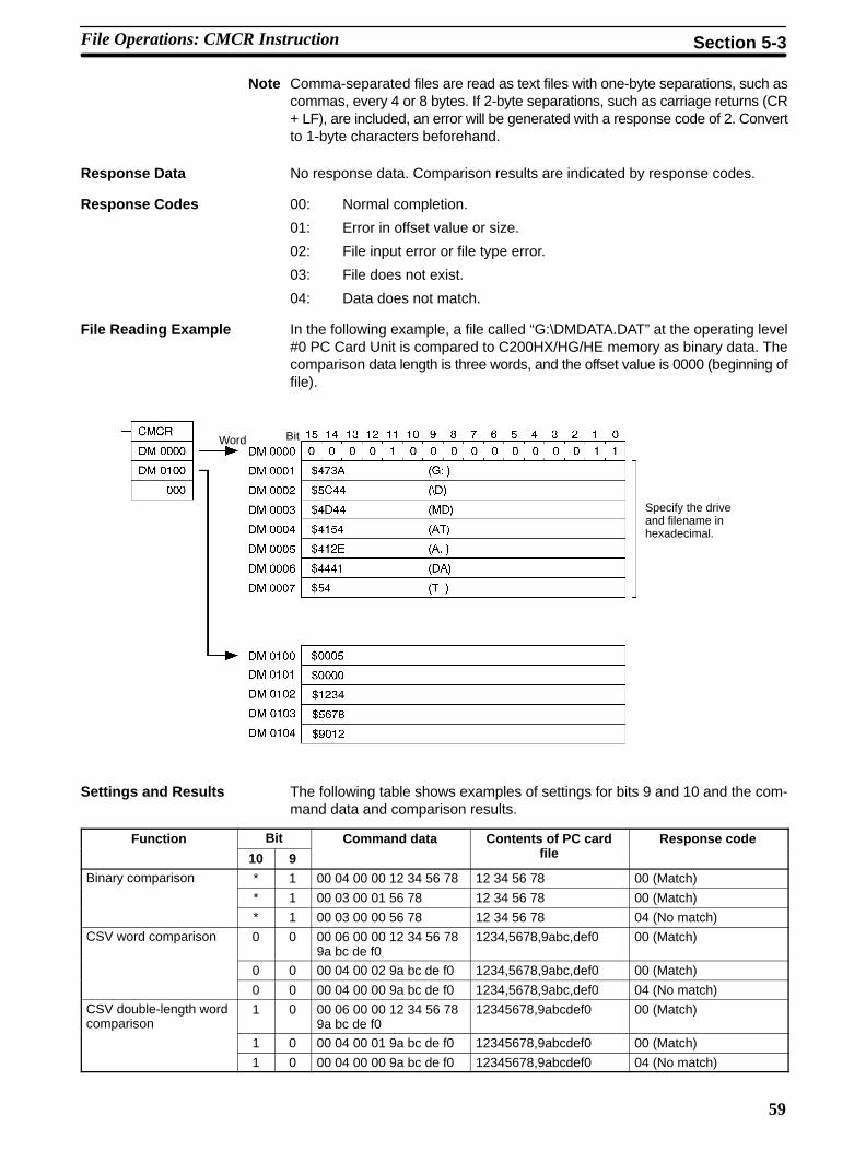
59
Note Comma-separated files are read as text files with one-byte separations, such ascommas, every 4 or 8 bytes. If 2-byte separations, such as carriage returns (CR+ LF), are included, an error will be generated with a response code of 2. Convertto 1-byte characters beforehand.
Response Data No response data. Comparison results are indicated by response codes.
Response Codes 00: Normal completion.
01: Error in offset value or size.
02: File input error or file type error.
03: File does not exist.
04: Data does not match.
File Reading Example In the following example, a file called “G:\DMDATA.DAT” at the operating level#0 PC Card Unit is compared to C200HX/HG/HE memory as binary data. Thecomparison data length is three words, and the offset value is 0000 (beginning offile).
Word Bit
Specify the driveand filename inhexadecimal.
Settings and Results The following table shows examples of settings for bits 9 and 10 and the com-mand data and comparison results.
Function Bit Command data Contents of PC card Response code
10 9 file
Binary comparison * 1 00 04 00 00 12 34 56 78 12 34 56 78 00 (Match)
* 1 00 03 00 01 56 78 12 34 56 78 00 (Match)
* 1 00 03 00 00 56 78 12 34 56 78 04 (No match)
CSV word comparison 0 0 00 06 00 00 12 34 56 789a bc de f0
1234,5678,9abc,def0 00 (Match)
0 0 00 04 00 02 9a bc de f0 1234,5678,9abc,def0 00 (Match)
0 0 00 04 00 00 9a bc de f0 1234,5678,9abc,def0 04 (No match)
CSV double-length wordcomparison
1 0 00 06 00 00 12 34 56 789a bc de f0
12345678,9abcdef0 00 (Match)
1 0 00 04 00 01 9a bc de f0 12345678,9abcdef0 00 (Match)
1 0 00 04 00 00 9a bc de f0 12345678,9abcdef0 04 (No match)
File Operations: CMCR Instruction Section 5-3

60
5-3-10 File Search (Process No. 4)The File Search process searches files, by specified data, on a memory card inthe PC Card Unit.
Control Data
Control code
•••
Control code
C+1
to
C+7
Word Port No. Process No.
15 14 13 12 11 10 9 8 7 6 5 4 3 2 1 0
C+0
Bit
Level (0/1) Port No. 0 0 0 0 0 1 0 01
• (Operating) LevelSetting to “0” specifies level #0; setting to “1” specifies level #1.
• Control Code EnableFixed at “1” (control codes enabled).
• Port Number
Bit 9 0: Searches as comma separated values. The separation methodis determined by bit 10.
1: Searches as binary file.
Bit 10 0: Puts comma separation in single word units (one word).
1: Puts comma separation in double word units (two words).
• Control CodeInput in hexadecimal values the drive and filename for the file to be searched.The extension must be written in three characters. Shift JIS 1-byte alphanu-meric code is used.
Slot 1 is drive G, and slot 2 is drive H.
Command Data
Data length Offset
Search data
2 or 4 bytes
• Data LengthFor word comparison, specify “3” and for double-length word comparisonspecify “4.” For binary, specify “3.”
• OffsetThe offset specifies the search data offset. For binary files it is specified by thenumber of words, and for comma separated files it is specified by the numberof elements. Specify a number from 0 to FFFF in hexadecimal.
• Search DataThe length of the search data depends on the type of file created, as follows:
Single-word comma separation, binary: One word
Double-word comma separation: Two words
Note Comma-separated files are read as text files with one-byte separations, such ascommas, every 4 or 8 bytes. If 2-byte separations, such as carriage returns (CR+ LF), are included, an error will be generated with a response code of 2. Convertto 1-byte characters beforehand.
File Operations: CMCR Instruction Section 5-3

61
Response Data When the search data is found, the location of the matching data is stored. It isreturned as data within a range of 0 to FFFF.
The word location of matching data is as indicated as being a certain number ofwords from the specified offset, i.e., the first word after the offset becomes 0000;the second word, 0001; the third word, 0002, etc.
Response Codes 00: Normal completion.
01: Parameter error (for example, if the data length is 3 for double wordcomparison).
02: File input error or file type error.
03: File does not exist.
File Reading Example In the following example, the contents (single-word comma separation) of a filecalled “G:\DMDATA.DAT” at the operating level #0 PC Card Unit is searched forthe specified data in C200HX/HG/HE memory. The offset is 0000 and the searchdata is $5678. The contents of DMDATA.DAT is 0000, 1234, 5678, 9123, 4560,0000, 1111.
Word Bit
Specify the driveand filename inhexadecimal.
Indicates a match with the third element.
Settings and Results The following table shows examples of settings for bits 9 and 10 and the com-mand data and search results.
Function Bit Command data Contents of file Response data
10 9 (location of match)
Binary search * 1 00 03 00 01 9a bc 12 34 56 78 9a bc de f0 00 01
CSV word search 0 0 00 03 00 01 9a bc 1234,5678,9abc,def0 00 01
CSV double-lengthword search
1 0 00 04 00 01 9a bc de f0 12345678,9abcdef0 00 00
File Operations: CMCR Instruction Section 5-3

62
5-3-11 File Precautions
• When comma-separated files are written by CMCR, they are written as oneline.
• Comma-separated files created at a personal computer are read with theassumption that they were created in one of the following formats.
4 bytes, comma, 4 bytes, comma, 4 bytes, comma....
8 bytes, comma, 8 bytes, comma, 8 bytes, comma....
• Additional data can only be written to a file if there is space available on thecard, and file data can only be overwritten in the range where an offset can bespecified.
• Individual fields in comma separated files are not enclosed by quotationmarks.
5-4 Memory Card Access Times for CMCR InstructionsThe minimum times for executing CMCR instructions are as follows:
Minimum CMCR Instruction Execution Times
Unit processing time B
CMCR instructionexecuted Completed
Local nodecycle time
Unit processingtime A
Memory Card access time
The access time will differ depending on the type of Memory Card used, so in thisinstance it is calculated as 0.
Minimum CMCR Instruction Execution Time = local node cycle time + Unit processing time A + Memory Card access time + Unit processing time B + local node cycle time.
• Unit Processing Time ATime to write data on the card: no. of write words × 0.013 + 5 msTime to read data from a card: 5 ms
• Unit Processing Time BTime to write data on the card: 5 msTime to read data from a card: no. of read words × 0.013 + 5 ms
Example:The minimum instruction execution time for writing 999 words
Local node cycle time × 2 + 999 × 0.013 + 5 ms + 5ms = local node cycle time × 2 + 22.987 ms
Actual Measurement Values The write time for a 999-word SRAM card: 24 ms
The write time for a 1-word SRAM card: 9.7 ms
When a PC Card Unit is connected to the C200HX/HG/HE CPU, the cycle timewill be delayed by a maximum of 6 ms.
C200HX/HG/HE Cycle DelayTime
Memory Card Access Times for CMCR Instructions Section 5-4

63
5-5 Sample ProgramThis section provides a sample program for writing and reading files. In this pro-gram, when execution condition IR 00000 is turned from OFF to ON and thenOFF again, the data in 100 DM words beginning with DM 0100 is written toG:\DMSAVE.DAT. When execution condition IR 00001 is turned from OFF to ONand then OFF again, the 100 words of data is read from DMSAVE.DAT to the DMwords from DM 0200 onwards.
Program
Executioncondition
0000025201: Operating level #0 CMCR execution enabled.
Operating level #0File write (newly created)(Single-word comma separated file)
Process No. 1, File WriteCommand execution
00300: Output for CMCR instruction error.
00101: CMCR execution completion
25201: Operating level #0 CMCR execution enabled.
Operating level #0File read (newly created)(Single-word comma separated file)
Process No. 2, File ReadCommand execution
00301: Output for CMCR instruction error
00201: CMCR execution completion
Executioncondition
00001
Sample Program Section 5-5

64
DM Area Settings
Control data
Fixed at 0003.
Offset: 0
Read data length: 100 words
Write data length: 102 words
Offset: 0
0003
0000
0064
47
5C
4D
41
45
44
54
3A
44
53
56
2E
41
DM0000
DM0001
DM0002
DM0003
DM0004
DM0005
DM0006DM0007
‘G’, ‘:’
‘\’, ‘D’
‘M’, ‘S’
‘A’, ‘V’
‘E’, ‘.’
‘D’, ‘A’
‘T’
0102
0000
Data
:
Data
DM0010
DM0011
DM0012
DM0098
DM0099
DM0100
DM0199
5-6 Debugging Ladder ProgramsThis section shows how to debug the ladder program, using the sample programprovided in 5-5 Sample Program as an example.
Procedure The procedure for debugging a ladder program is outlined below. Each of thesesteps is then explained in more detail.
1, 2, 3... 1. Start up the Support Software.
2. Allocate a function code to CMCR.
3. Create the ladder program.
4. Go online.
5. Transfer the program to the PC.
6. Prepare the system for debugging.
7. Execute the program.
8. Debug the program.
9. Check the write data.
Support Software Startup From the drive in which the SYSMAC Support Software is installed, enter “SSS”and then press the Enter key to start up the SYSMAC Support Software. Then,from the System Setup menu, set the PC model, PC communications parame-ters, and so on.
Expansion Instruction Setup Select “X:Set instructions” from the Utility Menu. Then use “E:Edit instructions”to set a function code for the CMCR instruction in the instructions table. Fordetails, refer to the SYSMAC Support Software Operation Manual: C-seriesPCs.
The settings can also be made using the Programming Console. For details,refer to 4-1-3 Allocating a Function Code for CMCR.
Ladder Program Creation Create the sample program.
Online Connection Go online by pressing Ctrl+O followed by the F1 key (PC connection).
Program Transfer Use “Monitoring/P:Transfer program/W:Computer → PC” to transfer the pro-gram to the C200HX/HG/HE Programmable Controller.
Debugging Ladder Programs Section 5-6

65
Debug Preparation Insert the memory card into slot 1 in the PC Card Unit. Set the control data, datalength, offset, and write data to the DM area using the DM Menu.
Program Execution Press Ctrl+O followed by the F3 key (MONITOR) to switch to MONITOR mode.
Debugging Use the “Monitor data” operation under the Monitoring Menu to execute the writecommand by turning execution condition IR 00000 from OFF to ON and backOFF.
Check to see that error output IR 00300 does not turn ON. If it does turn ON, useCMCR response codes 23700 to 23707 to check the error.
Execute the read command by turning execution condition IR 00001 from OFFto ON and back OFF.
Just as for the write command, check to see that error output IR 00301 does notturn ON, and check the response codes if it does.
Use the DM Menu to check to see that the contents of DM 0100 to DM 0199 havebeen copied to DM 0200 to DM 0299.
Checking the Write Data Eject the memory card from the PC Card Unit.
Insert the memory card in a personal computer with a 3G8F5-PCM01 PC CardInterface Board installed, or in a computer with a PC card slot.
Check to see that a file called “DMSAVE.DAT” has been created on the memorycard. This is a text data file, in single-word comma separated value format.
This completes the ladder program debugging operation.
Debugging Ladder Programs Section 5-6

67
Part 3Using Ethernet
This part of the manual describes how to install Ethernet Cards and usethe setup software. It includes directions on how to use the SEND andRECV instructions to transfer data and provides details on the FINScommands and responses used for communications between theC200HX/HG/HE CPU and the PC Card Unit.

69
SECTION 6Preparations for Operation
This section outlines the steps required to install the PC Card Unit and Ethernet function and prepare for operation. Be sureyou have read this section and understood all of the procedures before attempting to actually make the settings or do any pro-gramming.
6-1 Outline 70. . . . . . . . . . . . . . . . . . . . . . . . . . . . . . . . . . . . . . . . . . . . . . . . . . . . . . . . . . . . . . . . . 6-2 Procedures 70. . . . . . . . . . . . . . . . . . . . . . . . . . . . . . . . . . . . . . . . . . . . . . . . . . . . . . . . . . . . . . 6-3 Communications 72. . . . . . . . . . . . . . . . . . . . . . . . . . . . . . . . . . . . . . . . . . . . . . . . . . . . . . . . . .
6-3-1 Outline 72. . . . . . . . . . . . . . . . . . . . . . . . . . . . . . . . . . . . . . . . . . . . . . . . . . . . . . . . . . 6-3-2 Ethernet Communications Function 72. . . . . . . . . . . . . . . . . . . . . . . . . . . . . . . . . . . 6-3-3 SEND and RECV 73. . . . . . . . . . . . . . . . . . . . . . . . . . . . . . . . . . . . . . . . . . . . . . . . . . 6-3-4 FINS Communications Service (FINS Commands and Responses) 73. . . . . . . . . . . 6-3-5 Socket Services 73. . . . . . . . . . . . . . . . . . . . . . . . . . . . . . . . . . . . . . . . . . . . . . . . . . .

70
6-1 OutlineThe procedures required to prepare for operation are outlined below. Be sure tofamiliarize yourself with these basic procedures.
These procedures are explained in more detail in 6-2 Procedures.
1, 2, 3... 1. Communications Board Installation
Mount the Communications Board in the C200HX/HG/HE CPU.
2. C200HX/HG/HE Setup
Assign a function code to the CARD MACRO (CMCR) expansion instruc-tion.
3. PC Card Unit Setup
Mount the PC Card Unit and make the required settings.
4. Ethernet Setup
Install the Ethernet Card and set up Ethernet using the setup software sothat the communications software can be used.
5. Programming
Write the program.
6. Debugging
Debug the program.
7. Operation
6-2 ProceduresThis section outlines the procedures required to install and set up the PC CardUnit and peripheral devices for application development and operation. Be surethat you thoroughly understand all of these procedures. References for furtherreading are provided for each procedure.
1. Communication Board Mount either the C200HW-COM01 or C200HW-COM04-E CommunicationsBoard in the C200HX/HG/HE CPU. Refer to the C200HW-COM01 to 06-E Com-munications Board Operation Manual for details.
2. C200HX/HG/HE Setup Two steps are require to prepare the C200HX/HG/H for PC Card Unit applica-tion.
• Addition of CMCR
Use either the SYSMAC Support Software or the Programming Console toassign a function code to the CARD MACRO (CMCR) instruction.
• System Switch Setting
Turn ON DIP switch pin number 4 to enable setting expansion instructionsfor the C200HX/HG/HE.
3. PC Card Unit Setup Two steps are required to set up the PC Card Unit.
• System Switch Setting
Set the startup mode, memory card initialization type, the operating level,etc. If only the memory card function is to be used, set only the operatinglevel and leave the other pins set to OFF.
• Unit and Peripheral Connections
Mount the PC Card Unit on the Backplane and install the Bus ConnectionUnit and memory card.
4-1
4-1
4-3
4-4 to 4-6
Procedures Section 6-2

71
Unit Restrictions and Mounting Locations
When a PC Card Unit is used, only one SYSMAC LINK Unit or SYSMACNET Link Unit can be used on the CPU Backplane.
When a PC Card Unit and SYSMAC LINK Unit or SYSMAC NET Link Unitare used together on the CPU Backplane, they must be mounted in the slotsshown in the following illustration.
SYSMAC LINK Unit
Mount the PC Card Unit to theleft of the SYSMAC LINK Unit
C200HX/HG/HE CPUPC Card Unit
4. Ethernet Setup
• Ethernet Card Installation
Install the Ethernet Card into the PC Card Unit.
• Ethernet Connection
Connect the PC Card Unit to the Ethernet network.
• Personal Computer Setup
Connect the PC Card Unit to a personal computer and copy the setup soft-ware.
• Setup Software Settings
Activate the setup software on the personal computer and carry out all set-tings for Ethernet.
5. Programming
Use SYSMAC Support Software with a personal computer to create the ladderprogram. For details regarding ladder programming, refer to the SYSMAC Sup-port Software Operation Manuals.
6. Program Debugging Use a memory card with the program that has been created and correct anybugs that may be found.
7. Operation Proceed with actual operation.
Note 1. Do not use the setup software for the C200HW-PCS01(-EV1) to performsettings for the C200HW-PCS01-V2.
2. The C200HW-PCS01-V2 is factory-set to ODI driver (cntpclat.com). For thisreason, if the Unit is started up without installing the C-NET(PC)C-10LEthernet Card made by CONTEC, the ERR indicator will light. Perform therequired settings for the ODI driver and Ethernet communications accordingto the Ethernet Card used.
7-2
7-3
7-4
7-5 and 7-6
8 to 11
Procedures Section 6-2

72
6-3 Communications
6-3-1 OutlineThe PC Card Unit has a built in message service that enables the use of datacommunications and commands to control PCs and FA computers on nodes ona network.
The message service operates by setting the communications destination eachtime it sends a command or data and then receives the response from the des-tination node. The message service can be set so as not to send any response ifa response is not necessary. A message can be sent to all nodes on the networksimultaneously. This is called broadcasting.
The PC Card Unit can participate in communications with C200HX/HG/HECPUs, CV-series PCs, and computers on the Ethernet network.
Node-to-node Data Transfer
Response
C200HX/HG/HE+
PC Card Unit
CV+
Ethernet Unit
CVM1+
Ethernet Unit
C200HX/HG/HE+
PC Card Unit
FA computer
Command
Broadcasting
C200HX/HG/HE+
PC Card Unit
CV+
Ethernet Unit
CVM1+
Ethernet Unit
C200HX/HG/HE+
PC Card Unit
FA computer
Broadcast data
There are three communications systems used by the message service for thePC Card Unit: ladder diagram instructions (SEND and RECV), FINS commands,and socket services. These are detailed next.
6-3-2 Ethernet Communications FunctionThe C200HW-PCS01-V2 PC Card Unit Ethernet Set supports the three commu-nications methods shown in the following diagram.
Overview
Ethernet communications
SEND/RECV instructions
FINS communications service
Socket services
Communications Section 6-3

73
Software Configuration
Note FINS commands are issued by using CMCR.
PC Card Unit
Ethernet Card
SEND
RECV
CMCR
CMCR CMCR
The three communication methods are outlined below.
6-3-3 SEND and RECVData is transmitted from the PC Card Unit using the SEND and RECV instruc-tions. Although it is necessary to specify the data for transmission, detailed dataprocessing is automatically performed by the Unit.
Refer to Section 8 Using SEND(90) and RECV(98) for details on SEND andRECV.
6-3-4 FINS Communications Service (FINS Commands and Responses)The FINS communication service is explained below in three categories: whenthe PC Card Unit receives a FINS command; when a FINS command is sentfrom the PC Card Unit; and when FINS communication is carried out betweenthe computer and the PC Card Unit.
For details on FINS commands and responses, refer to Section 9 FINS Com-mands and Section 11 Using FINS Commands and Responses.
When the PC Card Unit Receives a FINS CommandWhen the PC Card Unit receives a FINS command, it automatically interpretsthe command and sends a response. All processing is conducted automatically,so there is no need to program the PC to respond to FINS commands.
When a FINS Command is Sent From the PC Card UnitA FINS command is issued using the CMCR instruction, and a response isreturned from the recipient of the command. That response is returned automat-ically if the recipient of the FINS command is a C200HX/HG/HE or CVM1/CVProgrammable Controller.
FINS Communication Between the Computer and the PC Card UnitTo use FINS commands from a computer, create the command data in the pro-gram at the computer according to the FINS command format. Have the FINSresponses that are returned form the PC Card Unit analyzed and processedaccording to that format. For details, refer to Section 9 FINS Commands.
6-3-5 Socket ServicesA socket is an interface which allows a user program to directly use TCP (Trans-mission Control Protocol) and UDP (User Datagram Program). Socket servicesare employed by using the CMCR instruction. Using socket services allows thePC Card Unit to communicate with UNIX workstations and FA Computers otherthan OMRON Programmable Controllers, with any protocol. For details, refer toSection 10 Socket Services.
Communications Section 6-3

75
SECTION 7Setting Up Ethernet
This section describes how to install Ethernet cards and use the setup software. Before setting up Ethernet, always set up thePC Card Unit as described in Section 4 Installation and Switch Settings.
7-1 Preparations 76. . . . . . . . . . . . . . . . . . . . . . . . . . . . . . . . . . . . . . . . . . . . . . . . . . . . . . . . . . . . . 7-2 Installing and Removing the Ethernet Card 76. . . . . . . . . . . . . . . . . . . . . . . . . . . . . . . . . . . . .
7-2-1 Ethernet Cards 76. . . . . . . . . . . . . . . . . . . . . . . . . . . . . . . . . . . . . . . . . . . . . . . . . . . . 7-2-2 PC Card Slots 77. . . . . . . . . . . . . . . . . . . . . . . . . . . . . . . . . . . . . . . . . . . . . . . . . . . . . 7-2-3 Installing and Removing an Ethernet Card 77. . . . . . . . . . . . . . . . . . . . . . . . . . . . . .
7-3 Connecting to the Ethernet Network 81. . . . . . . . . . . . . . . . . . . . . . . . . . . . . . . . . . . . . . . . . . 7-3-1 Connecting to the Hub 81. . . . . . . . . . . . . . . . . . . . . . . . . . . . . . . . . . . . . . . . . . . . . . 7-3-2 Constructing an Ethernet Network 82. . . . . . . . . . . . . . . . . . . . . . . . . . . . . . . . . . . .
7-4 Connecting to the Personal Computer 82. . . . . . . . . . . . . . . . . . . . . . . . . . . . . . . . . . . . . . . . . 7-4-1 Restrictions on Personal Computers 82. . . . . . . . . . . . . . . . . . . . . . . . . . . . . . . . . . . 7-4-2 Connecting the Computer to the PC Card Unit 82. . . . . . . . . . . . . . . . . . . . . . . . . . .
7-5 Setting Up the Ethernet Environment 84. . . . . . . . . . . . . . . . . . . . . . . . . . . . . . . . . . . . . . . . . 7-5-1 IP Address 84. . . . . . . . . . . . . . . . . . . . . . . . . . . . . . . . . . . . . . . . . . . . . . . . . . . . . . . 7-5-2 Subnet Mask 85. . . . . . . . . . . . . . . . . . . . . . . . . . . . . . . . . . . . . . . . . . . . . . . . . . . . . 7-5-3 ODI Driver 85. . . . . . . . . . . . . . . . . . . . . . . . . . . . . . . . . . . . . . . . . . . . . . . . . . . . . . . 7-5-4 Hosts 85. . . . . . . . . . . . . . . . . . . . . . . . . . . . . . . . . . . . . . . . . . . . . . . . . . . . . . . . . . . 7-5-5 Conversion Table for IP Addresses and FINS Node Addresses 85. . . . . . . . . . . . . . 7-5-6 FINS Routing Tables 86. . . . . . . . . . . . . . . . . . . . . . . . . . . . . . . . . . . . . . . . . . . . . . . 7-5-7 Gateway Address 87. . . . . . . . . . . . . . . . . . . . . . . . . . . . . . . . . . . . . . . . . . . . . . . . . . 7-5-8 Other Ethernet Environment Settings 87. . . . . . . . . . . . . . . . . . . . . . . . . . . . . . . . . . 7-5-9 Setting the Port Number 87. . . . . . . . . . . . . . . . . . . . . . . . . . . . . . . . . . . . . . . . . . . .
7-6 Setup Software Operation 88. . . . . . . . . . . . . . . . . . . . . . . . . . . . . . . . . . . . . . . . . . . . . . . . . . 7-6-1 Setup Procedure 88. . . . . . . . . . . . . . . . . . . . . . . . . . . . . . . . . . . . . . . . . . . . . . . . . . . 7-6-2 Preset Items 88. . . . . . . . . . . . . . . . . . . . . . . . . . . . . . . . . . . . . . . . . . . . . . . . . . . . . . 7-6-3 Connecting to the PC Card Unit 89. . . . . . . . . . . . . . . . . . . . . . . . . . . . . . . . . . . . . . 7-6-4 Starting and Exiting the Software 91. . . . . . . . . . . . . . . . . . . . . . . . . . . . . . . . . . . . . 7-6-5 IP Address 92. . . . . . . . . . . . . . . . . . . . . . . . . . . . . . . . . . . . . . . . . . . . . . . . . . . . . . . 7-6-6 Subnet Mask 92. . . . . . . . . . . . . . . . . . . . . . . . . . . . . . . . . . . . . . . . . . . . . . . . . . . . . 7-6-7 ODI Driver 93. . . . . . . . . . . . . . . . . . . . . . . . . . . . . . . . . . . . . . . . . . . . . . . . . . . . . . . 7-6-8 HOSTS File 94. . . . . . . . . . . . . . . . . . . . . . . . . . . . . . . . . . . . . . . . . . . . . . . . . . . . . . 7-6-9 Address Conversion Table 96. . . . . . . . . . . . . . . . . . . . . . . . . . . . . . . . . . . . . . . . . . . 7-6-10 FINS Routing Tables 98. . . . . . . . . . . . . . . . . . . . . . . . . . . . . . . . . . . . . . . . . . . . . . . 7-6-11 Gateway Address 99. . . . . . . . . . . . . . . . . . . . . . . . . . . . . . . . . . . . . . . . . . . . . . . . . . 7-6-12 Returning the PC Card Unit to Normal Mode 100. . . . . . . . . . . . . . . . . . . . . . . . . . . .
7-7 Backing Up and Restoring Settings 100. . . . . . . . . . . . . . . . . . . . . . . . . . . . . . . . . . . . . . . . . . . 7-7-1 Backing Up Files 100. . . . . . . . . . . . . . . . . . . . . . . . . . . . . . . . . . . . . . . . . . . . . . . . . . 7-7-2 Restoring Files 102. . . . . . . . . . . . . . . . . . . . . . . . . . . . . . . . . . . . . . . . . . . . . . . . . . . .

76
7-1 PreparationsBefore setting up the Ethernet, always perform the setup procedure describedbelow.
Note 1. Do not use the setup software for the C200HW-PCS01(-EV1) to performsettings for the C200HW-PCS01-V2.
2. The C200HW-PCS01-V2 is factory-set to ODI driver (cntpclat.com). For thisreason, if the Unit is started up without installing the C-NET(PC)C-10LEthernet Card made by CONTEC, the ERR indicator will light. Perform therequired settings for the ODI driver and Ethernet communications accordingto the Ethernet Card used.
3. The service conditions, slots used, and restrictions on PC cards are thesame for the PC Card Unit Ethernet Set as for the PC Card Unit. Be sure toobserve the restrictions described in Section 4 Installation and Switch Set-tings.
1, 2, 3... 1. Mounting the Communications Board
Mount the C200HW-COM01 or C200HW-COM04-E CommunicationsBoard in the C200HX/HG/HE CPU. Refer to the C200HW-COM01 to 06-ECommunications Board Operation Manual for details.
2. Setting Up the C200HX/HG/HE
• Adding CMCR
Use the SYSMAC Support Software or Programming Console to allocate afunction code to the CMCR instruction (CARD MACRO instruction).
• Setting the System Switch
Turn ON pin no. 4 on the DIP switch to enable allocating function codes toexpansion instructions for the C200HX/HG/HE.
3. Setting Up the PC Card Unit
• Setting the System Switch
Set the startup mode, memory card format, operating level, etc. If only amemory card is to be used, set the operating level only. Other pins can be leftOFF.
• Connecting the PC Card Unit to PeripheralsInstall the PC Card Unit on the CPU Backplane, and mount a Bus Connec-tion Unit and memory card.
7-2 Installing and Removing the Ethernet CardThis section describes restrictions on Ethernet cards and explains how to install/remove an Ethernet card in/from the PC Card Unit.
7-2-1 Ethernet Cards
Applicable Ethernet Cards The PC Card Unit uses a DOS ODI driver. Although two DOS ODI drivers arecurrently in existence (SPEC3 and SPEC4), the PC Card Unit supports theSPEC3 ODI driver only. Therefore, Ethernet cards that have only the SPEC4ODI driver cannot be used.
Note 1. Before installing or removing an Ethernet card, always turn the PC Card UnitOFF. An Ethernet card cannot be installed or removed while the PC CardUnit is ON.
2. Only one Ethernet card can be used.
4-1
4-1
4-3
4-4 to 4-6
Installing and Removing the Ethernet Card Section 7-2

77
7-2-2 PC Card Slots
Slot 1
Slot 2
Slot 1: A type-I, -II, or -III PC card can be mounted in this slot.
Slot 2: A type-I or -II PC Card can be mounted in this slot. If, however, a type-IIIPC Card is mounted in slot 1, slot 2 cannot be used.
Note The card inserted into slot 2 can be removed or installed by loosening the setscrews on plate 2. When removing or installing a card into slot 1, always removeplate 2.
To avoid accidental removal of the Ethernet Card, it is recommended that theEthernet Card be installed in slot 1.
7-2-3 Installing and Removing an Ethernet Card
Note Use an Ethernet card that has a connector more than 3 mm away from the edgeof the card, as shown in the figure below. If the distance between the edge of thecard and the connector is 3 mm or less, the plate for securing the PC card cannotbe installed.
Ethernet cardFacingside
3 mm
Note There is a restriction on the current consumption of the Ethernet card. Use anEthernet card that meets the following conditions:I5V (1 slot) ≤ 0.5 A, I12V (1 slot) ≤ 0.1 AI5V (2 slots) + 3.4 x I12V (2 slots) ≤ 1.0 A
Installing and Removing the Ethernet Card Section 7-2

78
Installing an Ethernet Card
1, 2, 3... 1. Connect the attached adapter to the Ethernet card as shown in the figurebelow. Carefully check the shape of each connector to ensure correct con-nection. Be sure to press the connector all the way in.
2. Insert the Ethernet card into the PC card slot as shown in the figure below.Press the Ethernet card until its edge is aligned with the eject buttons.
To avoid accidental removal of the Ethernet Card, it is recommended thatthe Ethernet Card be installed in slot 1.
Eject buttons
Facingside
3. If a memory card is to be installed, install it in the same way as step 2.
4. Secure the Ethernet card with plate 2. To do so, secure plate 2 by tighteninga set screw into the plate 2 mounting hole in the front panel of the PC CardUnit as shown below.
Plate 2
Installing and Removing the Ethernet Card Section 7-2

79
5. Secure plate 3 by tightening a set screw into the plate 3 mounting hole.
Plate 3
6. Secure the adapter cable with plates 3 and 4 by tightening set screws asshown below.
Plate 4
Installing and Removing the Ethernet Card Section 7-2

80
Installation Precautions For the PC Card Unit Ethernet Set, consider the lengths of the cable and plate 3indicated in the figure below to ensure that there is sufficient room to install theEthernet Set properly.
Consider the length of this cable to ensure that there issufficient room to install the Ethernet Set.
Plate 3
Backplane
Removing an Ethernet Card
1, 2, 3... 1. Remove the set screw, then remove plate 2.
2. Remove the set screw, then remove plate 3.
3. Press the eject button as shown in the figure below.
The card inserted into slot 2 can be removed or installed by loosening the setscrews on plate 2. When removing or installing a card into slot 1, alwaysremove plate 2.
Note Do not press the eject button with the plates mounted.
Installing and Removing the Ethernet Card Section 7-2

81
7-3 Connecting to the Ethernet NetworkThis section explains connection to a 10BASE-T network as an example ofEthernet connection.
7-3-1 Connecting to the Hub1, 2, 3... 1. Connect the adapter from the Ethernet card to a twisted-pair cable.
Adapter
2. Connect the twisted-pair cable to the hub as shown below.
Connecting to the Ethernet Network Section 7-3

82
7-3-2 Constructing an Ethernet Network
The following diagram illustrates an example of Ethernet network configuration.For the types of networks and the types and number of devices that can be con-nected, refer to documentation for the hub.
A MAU is requiredto connect atwisted-pair cableto a CV SeriesEthernet Unit.
Hub
Personal computer
7-4 Connecting to the Personal ComputerThis section describes how to connect to a personal computer to enable usingthe setup software to set your Ethernet connection.
7-4-1 Restrictions on Personal Computers
Use a computer that meets the conditions shown below.
An AT or compatible computer can be used. The computer must have at leastone RS-232C port available.
Use an operating system supporting terminal software (e.g., HyperTerminal)that allows the exchange of binary files using the Zmodem protocol.Example: Windows 98 or Windows NT 4.0.
7-4-2 Connecting the Computer to the PC Card Unit
Connect the computer to the PC Card Unit with a Host Link Cable.
Note 1. Before connecting or disconnecting the cable, always turn both the PC CardUnit and the computer OFF.
2. If the computer does not have a 25-pin D-SUB connector RS-232C connec-tor, wire your own cable. Refer to Appendix C Connector Pin Assignmentsfor wiring.
Applicable Computers andOperating Systems
Connecting to the Personal Computer Section 7-4

83
1, 2, 3... 1. Open the front cover as shown below.
2. Connect the 9-pin D-SUB connector of the Host Link Cable to the serial com-munication connector on the PC Card Unit. Insert the connector all the wayin, then tighten the screws.
Front cover
3. Connect the 25-pin D-SUB connector of the Host Link Cable to the serialcommunication connector on the personal computer. Insert the connectorall the way in, then tighten the screws.
Connecting to the Personal Computer Section 7-4

84
7-5 Setting Up the Ethernet EnvironmentThe Ethernet communications environment must be set up to perform Ethernetcommunications from a PC Card Unit. This section describes how to set up theEthernet environment with the setup software.Refer to 7-6 Setup Software Operation for details on how to use the setup soft-ware.
7-5-1 IP AddressBecause a PC Card Unit uses an Ethernet expansion function (UDP/IP andTCP/IP), it must have its own IP address. An IP address is used to identify eachnode (such as computers, CV-series Ethernet Units, and PC Card Units) on anEthernet network. IP addresses must be set and managed to ensure that eachaddress is unique.
IP Address Structure An IP address is a 32-bit binary data, consisting of a network number and a hostnumber. The network number is an address used to identify each network. Thehost number is used to identify each host (i.e., node).IP addresses are divided into three classes: Class A, Class B, and Class C.Select an applicable class according to the scale of the network being used.
Class A Network no. (7 bits) Host number (24 bits)
1 1 0 Network number (21 bits) Host number (8 bits)
01 Network number (14 bits) Host number (16 bits)
0
0 8 31
0 1 16 31
0 1 2 24 31
Class B
Class C
Bit
Bit
Bit
The numbers of networks and hosts that can be identified differ according to theclass.
Class Number of networks Number of hosts
Class A Small More than 65536 (216)
Class B Medium 256 (28) to 65536 (216)
Class C Large Less than 256 (28)
An IP address consists of 32 bits divided into four segments of 8 bits each. Thesesegments are separated with a dot and represented as four decimal numbers.Example: 10000010 00111010 00010001 00100000 → 130.58.17.32
Note 1. All nodes within a network must have the same network number.2. The network number of an IP address is used to identify each Ethernet net-
work (IP network segment). The network number is not the same as the net-work address used for FINS communication.
3. An IP network segment is a logical network consisting of nodes that have thesame network number.
Assigning IP Addresses Assign a unique IP address to each node within a network (or among multiplenetworks).The internet protocol (IP) is a standard international communications protocol.Therefore, obtaining an IP address from a public organization prevents address-related problems when the network is expanded in the future. Obtaining an offi-cial IP address is not required for a local Ethernet network that is not connectedto outside networks. We do, however, recommend that you obtain an official IPaddress if there is any chance of connection to outside networks at any time inthe future.
Setting Up the Ethernet Environment Section 7-5

85
To assign an IP address to the PC Card Unit, select “1. Enter IP Address for Unit”from the main menu of the setup software. Refer to 7-6 Setup Software Opera-tion for details on how to specify the IP address.
7-5-2 Subnet MaskConnecting a lot of nodes to a network makes network operation and manage-ment difficult. In this case, it is better to construct the system by subdividing anetwork into multiple subnetworks. These subnetworks operate independentlywithin the network, but they are viewed as a single network from outside the net-work.To allow such network operations, the host number of the IP address must besubdivided into a host number and a subnet number.A subnet mask is the information used to identify which part of the host number isgoing to be used as the subnet number. All bits in the subnet mask that corre-spond to the bits in the IP address used either as the network number or the sub-net number are set to “1” and the remaining bits, which correspond to the bits inthe IP address actually used for the host number, are set to “0.” In the followingexample, only the last 8 bits are used as the host number.Example: 11111111 11111111 11111111 00000000 → FFFFFF00All nodes on a subnetwork must have the same subnet mask value.If no subnetwork is to be used, a subnet mask need not be specified. In this case,the subnet mask is recognized as the one that has no subnet number (or thatconsists of only the network number and host number).
To assign a subnet mask to a PC Card Unit, select “2. Enter Subnet Address forUnit” from the main menu of the setup software. Refer to 7-6 Setup SoftwareOperation for details on how to specify a subnet address.
7-5-3 ODI DriverSpecify the file name (including extension “.COM”) of the ODI driver providedwith the Ethernet card.To specify an ODI driver path, select “3. Enter ODI Driver Path” from the mainmenu of the setup software. Refer to 7-6 Setup Software Operation for details onhow to specify an ODI driver path.
7-5-4 HostsSpecify the IP addresses and host names of all the nodes to be registered in theIP network to be used. For a PC Card Unit, up to 127 nodes can be specified.Example:
IP address
128.0.1.1 master128.0.1.2 submaster
SpaceHost name
Set the hosts for the IP network to be used. To do so, an existing HOSTS file canbe copied, or a new HOSTS file can be created. Insert an space between the IPaddress and the host name. The maximum number of lines in a HOSTS file is127.To set the hosts, select “4. Edit HOSTS File” from the main menu of the setupsoftware. Refer to 7-6 Setup Software Operation for details on how to edit aHOSTS file.
7-5-5 Conversion Table for IP Addresses and FINS Node AddressesWhen a UDP/IP address has been used on the Ethernet an IP address must beused for the specified node address. Communications using FINS commands
Assigning an IP Address toa PC Card Unit
Specifying a Subnet Maskfor a PC Card Unit
Setting Up the Ethernet Environment Section 7-5

86
use a FINS node address. The conversion between the IP address and the FINSnode address is made in the PC Card Unit. The conversion table for IPaddresses and FINS node addresses shows the correspondence betweenFINS node addresses and IP addresses.
Specify IP addresses in decimal notation. If 0 is added to the beginning of eachfield, the address will be interpreted as an octal number. Enter an space betweenthe IP address and node address.
When using only the socket communications, also register the IP-FINS nodeaddress conversion table of the local node.
7-5-6 FINS Routing TablesThe FINS routing tables are required to return responses to FINS commandssent from a computer or CV-series PC on another network to the PC Card Unit.They show the route to each network to which response is to be returned.
The FINS routing tables consist of a local network table and a relay networktable.
Note Even if there is only one network, always specify the local network table. If thePC Card Unit is to communicate with a node on another network, the relay sta-tion must be a CV-series PC.
If routing tables are already set for C200HX/HG/HE Programmable Controllers,the PC Card Unit will use those routing tables. Routing tables established by thesetup software will be invalid.
Local Network Table Specify the unit no. of the PC Card Unit and the network address of the networkto which the PC Card Unit is connected.
• Local network address: Address of the network to which the PC Card Unit isconnected (1 to 127)
• Unit no.: 0 (fixed)
Relay Network Table The relay network table shows the route to each network with which the PC CardUnit is to communicate. This table need not be specified if the PC Card Unit is tocommunicate only with nodes within the local network.
• End network: Address of the network on which the destination node resides(1 to 127)
• Relay network: Address of the network linking the local node to the next relaynode (1 to 127)
• Relay node: Address of the relay node between the relay network and theend network (Ethernet Unit: 1 to 127)
To edit the routing tables, select “6. Edit Routing Table for FINS” from the mainmenu of the setup software. Refer to 7-6 Setup Software Operation for details onhow to edit the routing tables.
Setting Up the Ethernet Environment Section 7-5

87
7-5-7 Gateway AddressAn IP router can be used to connect multiple IP network segments. Networksconnected by an IP router can communicate with each other. FINS communica-tions allow nodes on different networks to communicate with one another as ifthese nodes are on the same network. To establish such communications, gate-way addresses must be specified.
Hostcomputer
PC CardUnit
IP router PC CardUnit
Ethernet network 1 Ethernet network 2
Hostcomputer
Hostcomputer
CV-seriesPC
Hostcomputer
Assign an identical value to the FINS network addresses of the Ethernet net-works connected by the IP router. (The network number or subnet number of theIP address, however, must be different for each network.) For example, the PCCard Units shown in the figure above have the same FINS network address(same layer).Broadcasting is not allowed between Ethernet networks connected by an IProuter. For example, data broadcast within Ethernet network 1 is not transmittedto nodes on Ethernet network 2.To specify a gateway address, select “7. Edit Gateway Address for Unit” from themain menu of the setup software. Refer to 7-6 Setup Software Operation fordetails on how to specify a gateway address.
7-5-8 Other Ethernet Environment SettingsThe following Ethernet environment settings cannot be changed for the PC CardUnit:• Broadcast address: All bits are fixed at 1.• Packet size: The size is fixed at 1,500 bytes. UDP data is split into 1,472-byte
data before transmission. TCP is 1,024 bytes.• KEEP ALIVE: Fixed at 60 seconds.• Send/Receive packet: Fixed at 2,048 bytes.
7-5-9 Setting the Port NumberIn the Ethernet Set, FINS communications are processed through the UDP port.The default port number is 9600.To change the port number, use the following procedure.
1, 2, 3... 1. With reference to the information on making backup copies in 7-7 BackingUp and Restoring Settings, make backup copies of the setting files.
2. Using the text editor of the personal computer, change the last line of theBASE.BAT file in the same folder as the setting files in the way shown below.Input the port number in decimal.base_e → base_e <port_number>
3. After saving the BASE.BAT file, with reference to the information on restor-ing files in 7-7 Backing Up and Restoring Settings, restore the BASE.BATfile.When the port number is changed, only the BASE.BAT file has to berestored. It is not necessary to restore other files.
Setting Up the Ethernet Environment Section 7-5

88
7-6 Setup Software Operation
7-6-1 Setup ProcedureThe procedure required for making Ethernet communications environment set-tings using the setup software is given below. The setup software is an applica-tion that operates on the PC Card Unit and is used from the terminal softwareinstalled on the personal computer.
1, 2, 3... 1. Turn OFF the power supply to the C200HX/HG/HE and the personal com-puter.
2. Connect the personal computer and the PC Card Unit using an RS-232Ccable. Refer to 7-4 Connecting to the Personal Computer for details.
3. Start up the terminal software and set the communications conditions.
4. Change the PC Card Unit’s startup mode (set pins 5 and 6 of the systemswitch to ON).
5. Turn ON the power supply to the C200HX/HG/HE and the personal com-puter.
6. Start up the setup software (SETUP.EXE) using the terminal software on thepersonal computer.
7. Make the Ethernet communications environment settings using the setupsoftware.
8. Restart the PC Card Unit in normal mode (i.e., with pins 5 and 6 of the sys-tem switch set to OFF). At this point the settings changes are enabled. Refer
to 7-6-12 Returning the PC Card Unit to Normal Mode for details.
Note 1. Do not use the setup software for the C200HW-PCS01(-EV1) to performsettings for the C200HW-PCS01-V2.
2. Backing Up and Restoring SettingsBefore changing settings using the setup software, it is recommended that abackup copy is made of the settings. Backing up and restoring settings isperformed not from the setup software, but from HyperTerminal. For detailsof the procedures, refer to 7-7 Backing Up and Restoring Settings.
7-6-2 Preset ItemsBefore starting Ethernet communications through the Ethernet card, use thesetup software to set up the Ethernet communications environment.
The items set using the setup software are described on the following pages.
Setup Software Operation Section 7-6

89
Menu Description
1. Enter IP address for UNIT Specify the IP address of the PC CardUnit.
2. Enter Subnet address for UNIT Specify the subnet mask of the PC CardUnit.
3. Enter ODI Driver Path. Specify the file name (including theextension “.COM”) of the ODI driverprovided with the Ethernet card.An ODI driver (cntpclat.com) for theC-NET(PC)C-10L Ethernet card madeby CONTEC is installed in the Unit.
4. Edit HOSTS File. Set the HOSTS file for the IP network.To do so, you can copy the existingHOSTS file or create a new HOSTS file.Insert a space between the IP addressand host name. The maximum numberof lines in the HOSTS file is 127.
5. Edit Conversion Table for IP addressand FINS Node address.
Specify the conversion correspondencebetween each pair of a FINS nodeaddress and IP address. Specify IPaddresses in decimal notation. Note thatif 0 is added to the beginning of eachfield, the address will be interpreted asan octal number. Enter a space betweenthe IP address and node address.
6. Edit Routing Table for FINS. Specify the data required forinternetwork communication. The dataconsists of a local network table and arelay network table. Even if there is onlyone network, specify just the localnetwork table. If the PC Card Unit is tocommunicate with a node on anothernetwork, the relay station must be aCV-series PC.
7. Edit Gateway address for UNIT Enter the IP address to be used as agateway with other Ethernet networks.
8. Display File Details. Not used.
9. Exit Exit the setup software to return to theDOS prompt.
7-6-3 Connecting to the PC Card UnitThe procedure for connecting to the PC Card Unit is given below. The connec-tion method is explained here using HyperTerminal, which is provided with Win-dows operating systems, as an example.
Before making the settings described below, connect the personal computerand the PC Card Unit using a Host Link Cable with reference to 7-4 Connectingto the Personal Computer.
Preset Items
Setup Software Operation Section 7-6

90
Change the PC Card Unit’s startup mode (system switch) by setting pins 5 and 6to ON.
Pin 6
Pin 5
HyperTerminal Startup and Initial Settings
1, 2, 3... 1. Start up HyperTerminal at the personal computer. The Connection Descrip-tion dialog box will be displayed.
2. Enter a name. In this example, the name “PCS” is used. Next, the dialog boxshown below will be displayed.
Select the COM port of thepersonal computer used.
Changing the Startup Mode(System Switch)
Setup Software Operation Section 7-6

91
3. Click the “OK” Button, and make the following communications settings inthe dialog box displayed next.
4. Click the “OK” Button.5. Turn ON the power supply to the PC Card Unit. (If the PC Card Unit has
already been started up, press ENTER.) The PC Card Unit will start up. Ifconnections have been made successfully, the following prompt will be dis-played.
::F: >
7-6-4 Starting and Exiting the SoftwareThis section describes how to start and exit the setup software.
Note Backing Up and Restoring SettingsBefore changing settings using the setup software, it is recommended that abackup copy is made of the settings. Backing up and restoring settings is per-formed not from the setup software, but from HyperTerminal. For details of theprocedures, refer to 7-7 Backing Up and Restoring Settings.
Starting the Setup Software1, 2, 3... 1. Enter “SETUP” from the terminal software.
Note For Japanese display, be sure to specify the “J” option. If this option is not speci-fied, messages will be displayed in English.
F: \>SETUP
Setup Software Operation Section 7-6

92
The setup software is started, and the following main menu appears on the dis-play:
1. Enter IP address for UNIT.2. Enter Subnet address for UNIT.3. Enter ODI Driver Path.4. Edit HOSTS File.5. Edit Conversion Table for IP address and FINS Node address.6. Edit Routing Table for FINS.7. Edit Gateway address for UNIT.8. Display File Details.9. Exit.
Select Number for Item (1–9):
2. Select an item by inputting a number between 1 and 9 and pressing ENTER.If a number between 1 and 7 is selected, the settings for that item can beread or changed.
Exiting the Setup Software Select “9. Exit” from the main menu.The setup software terminates and a prompt is displayed in the terminal soft-ware.
7-6-5 IP AddressSpecify the IP address of the PC Card Unit as described below.
1, 2, 3... 1. Select “1. Enter IP address for UNIT” from the main menu.
.
.Select Number for ITEM (1–9): 1Current IP address: 192.168.0.1New IP address:
2. Specify the IP address of the PC Card Unit. Input a decimal number.
New IP address: 123.45.67.89: 123.45.67.89 May I setup current data? (Y/N)
3. Make sure that the IP address is correct. Then, enter Y and press ENTER.The screen will return to the main menu. To cancel the setting, enter N andpress ENTER to return to the main menu.
Note When the IP address of the PC Card Unit has been changed, always select “4.Edit HOSTS File.” and set the HOSTS file.
7-6-6 Subnet MaskSpecify the subnet mask of the PC Card Unit as described below.
1, 2, 3... 1. Select “2. Enter Subnet address for UNIT” from the main menu.
.
.Select Number for ITEM (1–9): 2Current Subnet Mask: 255.255.255.0New Subnet Mask:
Setup Software Operation Section 7-6

93
2. Specify the subnet mask of the PC Card Unit. Input a decimal number.
New Subnet Mask: 255.255.0.0: 255.255.255.0 May I setup current data? (Y/N)
3. Make sure that the subnet mask is correct. Then, enter Y and press ENTER.The screen will return to the main menu. To cancel the setting, enter N andpress ENTER to return to the main menu.
7-6-7 ODI DriverSet the ODI driver to be used with the Ethernet card.
The default setting is “cntpclat.com.”
1, 2, 3... 1. Select “3. Enter ODI Driver Path.” from the main menu.
.
.Select Number for ITEM (1–9): 3Current ODI Driver : cntpclat.comEnter New ODI Driver Name : on-net-n.com
2. Enter an ODI driver name (including the extension “.COM”).The drive and the directory cannot be specified. Only the filename must bespecified.
oc-net-n.com : May I setup this new driver?If you press Y, current ODI driver is deletedand Unit gets waiting for file receiving.So please send a new ODI driver.If you press N, current ODI driver is selected. (Y/N)
Note After confirming that the current ODI driver is no longer required, enter Y andpress ENTER. (The current ODI driver will be erased.)
3. Make sure that the ODI driver name is correct. To cancel the setting, enter Nand press ENTER to return to the main menu. If Y is entered and ENTER ispressed, the PC Card Unit will go on standby to receive 1 file via the Zmo-dem protocol, and the following message will be displayed.
Please send a New ODI driver. B000000000aa51
4. After confirming that the PC Card Unit is on standby by checking that themessage above is displayed, start up the terminal software, and send thenew ODI driver to the PC Card Unit.
Setup Software Operation Section 7-6

94
Example: Procedure for HyperTerminal• Select “Transfer” and then “Send File.” The “Send File” dialog box shown
below will be displayed.
• Specify the path and file name of the ODI driver specified in step 2 and click the“Send” Button.
Note Be sure to select “Zmodem” as the protocol.
• The transfer will start and the following dialog box will be displayed.
• When transfer is completed, the screen will return to the setup software’s mainscreen.
7-6-8 HOSTS FileEdit the HOSTS file as described below.
If a HOSTS file already exists in your personal computer, copy the file before-hand. In each record of the HOSTS file, enter the IP address, a space, and thehost name in this order. Up to 127 nodes can be specified. An existing HOSTSfile can be used, but the maximum number of lines is still 127.
Example:
IP address
128.0.1.2 submaster
Host nameSpace
Setup Software Operation Section 7-6

95
1, 2, 3... 1. Select “4. Edit HOSTS File.” from the main menu.
(0)(1)(2)(3)(4)(5)(6)(7)(8)(9)Enter Number of Line To Change (0–9), Add Line (10), Delete Line (0–9), Display Previous Item (11), Display Next Item (12), End (13):
2. Select 0.
Enter Number of Line To Change (0–9), Add Line (10), Delete Line (0–9), Display Previous Item (11), Display Next Item (12), End (13): 0Enter New Address and Name:
3. Specify the IP address and host name of the remote node. To do so, enterthe IP address, a space, and the host name in this order.
Enter New Address and Name: 123.45.67.89 myaddress(0) 123.45.67.89 myaddress(1)(2)..(9)Enter Number of Line To Change (0–9), Add Line (10), Delete Line (0–9), Display Previous Item (11), Display Next Item (12), End (13):
4. Select 1, and specify the IP address and host name in the same way as forstep 3. Then, continue with this setting procedure for the rest of the HOSTSfile ((2) and onwards).
(0) 123.45.67.89 myaddress(1) 123.45.67.77 FA1(2) 123.45.67.78 FA2(3) 123.45.67.79 FA3(4) 123.45.67.80 FA4(5) 123.45.67.21 LAB1(6) 123.45.67.25 LAB2(7) 123.45.67.28 LAB3(8) 123.45.67.11 HO1(9) 123.45.67.12 HO2Enter Number of Line To Change (0–9), Add Line (10), Delete Line (0–9), Display Previous Item (11), Display Next Item (12), End (13):
• The screen only displays (0) to (9), as shown in the figure above.• To specify the line next to (9) (eleventh line), select “Add Line (10).”
Enter Number of Line To Change (0–9), Add Line (10), Delete Line (0–9), Display Previous Item (11), Display Next Item (12), End (13): 10Enter New Address and Name:
Setup Software Operation Section 7-6

96
• If an IP address and host name are entered, the display will change as shownbelow.
Enter New Address and Name: 123.45.67.13 HO3(0) 123.45.67.13 HO3(1)(2)..(9)Enter Number of Line To Change (0–9), Add Line (10), Delete Line (0–9), Display Previous Item (11), Display Next Item (12), End (13):
• Then, select the line on which an IP address and host name are to be entered(or select “Add Line (10)”), and enter the IP address and host name. Continuewith this setting procedure as required.
• To delete data from a line, select “Delete Line (0-9)”, enter the line number (0 to9), and press ENTER. When “Enter New Address and Name:” is displayed,press ENTER. The data is deleted from the line.
• Selecting “Display Previous Item (11)” scrolls up the screen to display the pre-vious 10 lines.
• Selecting “Display Next Item (12)” scrolls down the screen to display the next10 lines.5. After editing the HOSTS file, select “End (13).”
Enter Number of Line To Change (0–9), Add Line (10), Delete Line (0–9), Display Previous Item (11), Display Next Item (12), End (13): 13
The screen will return to the main menu.
7-6-9 Address Conversion TableEdit the conversion table file for IP addresses and FINS node addresses asdescribed below. Up to 127 nodes can be specified.
1, 2, 3... 1. Select “5. Edit Conversion Table for IP address and FINS Node address”from the main menu.
(0)(1)(2)(3)(4)(5)(6)(7)(8)(9)Enter Number of Line To Change (0–9), Add Line (10), Delete Line (0–9), Display Previous Item (11), Display Next Item (12), End (13):
As shown above, no addresses are registered as default settings.2. Select 0.
Enter Number of Line To Change (0–9), Add Line (10), Delete Line (0–9), Display Previous Item (11), Display Next Item (12), End (13): 0Enter New Address and Name:
Setup Software Operation Section 7-6

97
3. Specify the IP address of the remote node and the corresponding FINSnode address. To do so, enter the IP address, a space, and the FINS nodeaddress (0 to 127) in this order.
Enter New Address and Name: 123.45.67.89 14(0) 123.45.67.89 14(1)(2)..(9)Enter Number of Line To Change (0–9), Add Line (10), Delete Line (0–9), Display Previous Item (11), Display Next Item (12), End (13):
4. Select 1, and specify the IP address and the corresponding FINS nodeaddress in the same way as Step 3.Then, continue with this setting procedure for the rest of the conversiontable ((2) and onwards).Example:
(0) 123.45.67.89 14(1) 123.45.67.77 15(2) 123.45.67.78 16(3) 123.45.67.79 21(4) 123.45.67.80 22(5) 123.45.67.21 31(6) 123.45.67.25 32(7) 123.45.67.28 33(8) 123.45.67.11 40(9) 123.45.67.12 41Enter Number of Line To Change (0–9), Add Line (10), Delete Line (0–9), Display Previous Item (11), Display Next Item (12), End (13):
• The screen only displays (0) to (9) as shown in the figure above.• To specify the line next to (9) (eleventh line), select “Add Line (10).”
Enter Number of Line To Change (0–9), Add Line (10), Delete Line (0–9), Display Previous Item (11), Display Next Item (12), End (13): 10Enter New Address and Name:
• If an IP address and FINS node address are entered, the display is changed asshown below.
Enter New Address and Name: 123.45.67.13 42(0) 123.45.67.13 42(1)(2)..(9)Enter Number of Line To Change (0–9), Add Line (10), Delete Line (0–9), Display Previous Item (11), Display Next Item (12), End (13):
• Then, select the line on which an IP address and host name are to be entered(or select “Add Line (10)”), and enter the IP address and host name. Continuewith this setting procedure as required.
• To delete data from a line, select “Delete Line (0-9)”, enter the line number (0 to9), and press ENTER. When “Enter New Address and Name:” is displayed,press ENTER. The data is deleted from the line.
Setup Software Operation Section 7-6

98
• Selecting “Display Previous Item (11)” scrolls up the screen to display the pre-vious 10 lines.
• Selecting “Display Next Item (12)” scrolls down the screen to display the next10 lines.
5. After editing the Conversion Table for IP Address and FINS Node Address,select “End (13).”
Enter Number of Line To Change (0–9), Add Line (10), Delete Line (0–9), Display Previous Item (11), Display Next Item (12), End (13): 13
The screen will return to the main menu.
7-6-10 FINS Routing TablesEditing the routing tables for FINS is described next. Set the local network andrelay network.
Note Always specify both the local network and relay network during the editing pro-cedure. Even if only one of the networks needs to be modified, always performthe setting procedures for both of them.
1, 2, 3... 1. Select “6. Edit a Routing Table for FINS.” from the main menu.
1. Set My Network address2. Set Relay Network address3. ExitSelect Number of Item (1–3):
Local Network2. Enter 1 and press ENTER to select “1. Set My Network address.”
Select Number for ITEM (1–3): 1Current My Network address:New My Network address:
3. Specify the local network number. To do so, enter a local network no., aspace, and 0 (fixed) in this order. “0” is the unit no. of a PC Card Unit.
If a node number is to be specified from another node via FINS communica-tion, specify 16 ($10). The node no. of the C200HX/HG/HE CPU is 0.
New My Network address: 10: 10 May I setup current data? (Y/N)
4. Make sure that the local network number is correct. Then, enter Y and pressENTER. The screen will return to the screen displayed in Step 1. To cancelthe setting, enter N and press ENTER to return to the screen displayed inStep 1.
Setup Software Operation Section 7-6

99
Relay Networks5. Enter 2 and press ENTER to select “2. Set Relay Network address.”
Select Number for ITEM (1–3): 2(0)(1)(2)(3)(4)(5)(6)(7)(8)(9)Enter Number of Line To Change (0–9), Add Line (10), Delete Line (0–9), Display Previous Item (11), Display Next Item (12), End (13):
By default, nothing is yet registered, as shown above.6. Specify the relay network. To do so, enter the number of the network con-
taining the end target node (decimal number), a space, the local network no.(decimal number), a space, and the relay node no. in this order. (The relaynode no. is the number of the exit node within the local network that is usedto transfer data to the end target network.)Up to 127 networks can be specified.An example of specifying relay networks is shown below. The input proce-dure is the same as that described in 7-6-8 HOSTS File.
(0) 2 1 32 (Data is sent to the network via node 32.)(1) 3 1 33 (Data is sent to the network via node 33.)(2)(3)(4)(5)(6)(7)(8)(9)
7. After editing the relay network table, select “End (13).”
Enter Number of Line To Change (0–9), Add Line (10), Delete Line (0–9), Display Previous Item (11), Display Next Item (12), End (13):1. Set My Network address2. Set Relay Network address3. ExitSelect Number for ITEM (1–3):
8. Enter 3 and press ENTER to select “3. Exit.”The screen will return to the main menu.
7-6-11 Gateway Address1, 2, 3... 1. Select “7. Edit Gateway address for UNIT” from the main menu.
.
.Select Number for ITEM (1–9): 7Current Gateway address:New Gateway address:
Setup Software Operation Section 7-6

100
2. Enter the IP address of the node to be used as a gateway.
New Gateway address: 123.45.0.0: 123.45.0.0 May I setup current data? (Y/N)
3. Make sure that the IP address is correct. Then, enter Y and press ENTER.The screen will return to the main menu. To cancel the setting, enter N andpress ENTER to return to the main menu.
7-6-12 Returning the PC Card Unit to Normal ModeUse the following procedure to return the PC Card Unit to normal mode.
1, 2, 3... 1. Turn OFF the power to the C200HX/HG/HE and the personal computer.
2. Disconnect the RS-232C cable.
3. Change the PC Card Unit’s startup mode (system switch) by setting pins 5and 6 to OFF.
Pin 6
Pin 5
Pin 1(Sets operating level.)
4. Turn ON the power to the C200HX/HG/HE and the personal computer. ThePC Card Unit will start up in normal mode.
7-7 Backing Up and Restoring SettingsBefore changing the PC Card Unit’s Ethernet communications environment set-tings settings, it is recommended that a backup copy is made of the settings.
The methods for making a backup copy of the Ethernet communications envi-ronment settings stored in the PC Card Unit, and for restoring these settings tothe PC Card Unit are explained below.
7-7-1 Backing Up FilesUse the following procedure to make a backup copy of the Ethernet communica-tions environment settings saved in the PC Card Unit.
1, 2, 3... 1. Turn OFF the power supplies to the personal computer and the PC CardUnit.
2. Connect the personal computer and the PC Card Unit using a Host LinkCable. (Refer to 7-4 Connecting to the Personal Computer.)
Backing Up and Restoring Settings Section 7-7

101
3. Set pins 5 and 6 of the PC Card Unit’s system switch to ON, and start up thePC Card Unit.
4. Start up HyperTerminal at the personal computer and connect to the PCCard Unit. (Refer to 7-6 Setup Software Operation.)
5. At the HyperTerminal, select “Transfer” and “Receive File.” The “ReceiveFile” dialog box shown below will be displayed.
6. Specify the directory in which the backup file is to be saved, and click the“Close” Button.
Note 1. When making a backup copy, be sure to specify “Zmodem” under “Usereceiving protocol:.”
2. If “Zmodem with Crash Recovery” is selected, and backup is made severaltimes to the same directory, files with the same name will have a numberadded to the filename. When making backup copies more than once, use adifferent directory.
7. After the prompt, enter “backup” and press ENTER. Backup processing(i.e., transfer of the file from the PC Card Unit to the personal computer) isstarted, and the following dialog box is displayed.
When backup processing is completed, the screen will return to the promptscreen.
Note For details on the method for returning the PC Card Unit to normal mode, refer to7-6-12 Returning the PC Card Unit to Normal Mode.
If backup is completed successfully, the following 8 files are copied to the speci-fied directory in the personal computer.
Backed Up Files
Backing Up and Restoring Settings Section 7-7

102
aliasbase.batnet.cfgnowodiip_fins.filroute.filsetup.filhosts
Note When restoring files, be sure to transfer all of the above files to the PC Card Unit.
7-7-2 Restoring FilesUse the following procedure to restore the Ethernet communications environ-ment settings (which were backed up to the personal computer) to the PC CardUnit.
Note 1. Be sure to transfer all 8 backed up files to the PC Card Unit. For details onbacking up files, refer to 7-7-1 Backing Up Files.
2. With HyperTerminal, only one file can be sent for each transfer operation.Therefore, when restoring backed up files, the “Send File” operation mustbe performed 8 times.
1, 2, 3... 1. Turn OFF the power supplies to the personal computer and the PC CardUnit.
2. Connect the personal computer and the PC Card Unit using a Host LinkCable. (Refer to 7-4 Connecting to the Personal Computer.)
3. Start up HyperTerminal at the personal computer. (Refer to 7-6 Setup Soft-ware Operation.)
4. Set pin 5 of the system switch to ON, set pin 6 to OFF, and then start up thePC Card Unit.
E:\ftrans.exe f:\ /r /z /fFTRANS : File translate utility. Version 2.13Copyright (c) 1995, 1996 by NJK. All right reserved.Receive the file by Z modem.The directory name is f:\**B000000000aa51
5. At the HyperTerminal, select “Transfer” and “Send File.” The “Send File” dia-log box shown below will be displayed.
6. Specify the backup file to be restored.
Backing Up and Restoring Settings Section 7-7

103
7. Click the “Send” Button.
Normal End.
E:\>goto offon
E:\>urunon.exe
E:\>ftrans.exe f:\ /r /z /fFTRANS : File translate utility. Version 2.13Copyright (c) 1995, 1996 by NJK. All right reserved.Receive the file by Z modem.The directory name is f:\**B000000000aa51
8. Repeat steps 5 to 7 until all the backed up files have been transferred to thePC Card Unit. Refer to Backed Up Files on page 101 for the names of the files.
9. After the last file has been sent, confirm that the PC Card Unit is on standbyto receive files.
10. Set pins 5 and 6 of the PC Card Unit’s system switch to OFF, and then restartthe PC Card Unit. This will enable the restored Ethernet communicationsenvironment settings.
Backing Up and Restoring Settings Section 7-7

105
SECTION 8Using SEND(90) and RECV(98)
This section describes how to use the SEND(90) and RECV(98) instructions to transfer data.
8-1 Outline 106. . . . . . . . . . . . . . . . . . . . . . . . . . . . . . . . . . . . . . . . . . . . . . . . . . . . . . . . . . . . . . . . . 8-1-1 Specifying Destination Nodes 106. . . . . . . . . . . . . . . . . . . . . . . . . . . . . . . . . . . . . . . . 8-1-2 Communications Specifications 106. . . . . . . . . . . . . . . . . . . . . . . . . . . . . . . . . . . . . . 8-1-3 Send/Receive Data Areas 107. . . . . . . . . . . . . . . . . . . . . . . . . . . . . . . . . . . . . . . . . . . . 8-1-4 Instruction Status 107. . . . . . . . . . . . . . . . . . . . . . . . . . . . . . . . . . . . . . . . . . . . . . . . . . 8-1-5 SEND(90)/RECV(98)/CMCR Data Processing Timings 109. . . . . . . . . . . . . . . . . . .
8-2 SEND(90) 109. . . . . . . . . . . . . . . . . . . . . . . . . . . . . . . . . . . . . . . . . . . . . . . . . . . . . . . . . . . . . . . 8-3 RECV(98) 111. . . . . . . . . . . . . . . . . . . . . . . . . . . . . . . . . . . . . . . . . . . . . . . . . . . . . . . . . . . . . . . 8-4 Minimum Transmission Delay Time for SEND/RECV Instructions 113. . . . . . . . . . . . . . . . . .

106
8-1 OutlineThe SEND(90) and RECV(98) instructions are used in the PC user program tosend data from a PC to other nodes, such as PCs or computers.
8-1-1 Specifying Destination Nodes
Either of the following two communications modes is used depending on howdestination nodes are specified:
Node-to-node Data Transfer Data can be transferred between the local node and the destination node byspecifying the node address in the control data of the SEND(90) and RECV(98)instructions.
Send data
Receive data
Node 1 Node 2 Node 3 Node 4 Node 5
Broadcasting The same data can be sent to all nodes on the network by specifying 00 as thenode address of the destination node. In this case, no response is received fromthe nodes. (Broadcasting is not applicable to RECV(98).)
Broadcast data
Node 1 Node 2 Node 3 Node 4 Node 5
8-1-2 Communications Specifications
PC communications are based on the following specifications:
Item Specifications
Direction oftransmission
1:1 SEND(90) and RECV(98) instructions
1:N SEND(90) instruction (broadcast mode, no response,N = 127 or less)
Data length SEND(90): 1,000 words max. (2,000 bytes) (727 wordswhen data is broadcast or sent to local node)
RECV(98) : 1,000 words max. (2,000 bytes)
Data contents The following data is sent or received when each instruction isexecuted:
SEND(90): Data transmission request and response data
RECV(98): Data reception request and response data
Responsemonitoring time
00: Default (2.2 seconds)
01 to FF: User setting (approx. 0.1 to 25.5 seconds in 0.1 sincrements)
No. of retries 0 to F: 0 to 15 times
UDP Port No. 9600 is used for SEND/RECV.
Outline Section 8-1

107
8-1-3 Send/Receive Data Areas
The data areas that can be transferred using the SEND(90) and RECV(98)instructions differs according to the PC model being used. Check the operationmanual for your PC for details.
Send/Receive Data Areas
When remote node is C-series PC When remote node is CV-series PC
Area Areatype
Word addresses Area Areatype
Word addresses
IR and SR areas 00 0 to 511 CIO Area 00 0 to 2555
LR area (LR) 06 0 to 63 CPU Bus Link Area (G) 01 0 to 255
HR area (HR) 07 0 to 99 Auxiliary Area (A) 02 0 to 511
AR area (AR) 08 0 to 27 Timer Area (TIM) 03 0 to 1023
Timer/Counter Area(TIM/CNT)
03 0 to 511 Counter Area (CNT) 04 0 to 1023
DM Area (DM) 05 0 to 9999 DM Area (DM) 05 0 to 24575
Expansion DMBanks 0 to 7:Current bank:
10 to 1718
0 to 6143 Expansion DMBanks 0 to 7:Current bank:
10 to 1718
0 to 32765
Word Bits 15 to 08 Bits 07 to 04 Bits 03 to 00
D Area code 0 Word address
(D+1) Word address Word address Word address
Specified in binary coded decimal (BCD)
Set the send/receive area within the above ranges.
A data length of 1,000 words is valid only when the remote node supports it. If theremote node can only return 256 words, any data greater than 257 words is notguaranteed.
The PC Card Unit supports a data length of 1 to 997 words for the SEND(90)instruction, and a data length of 1 to 1,000 words for the RECV(98) instruction.
8-1-4 Instruction Status
Status information for executed SEND(90), RECV(98), and CMCR instructionsis reflected in the SR Area of the PC as instruction execution flags and instruc-tion response codes.
The following two instruction execution flags are used:
Instruction Enabled Flag: ON (“1”) when the SEND(90), RECV(98), or CMCR instruction can be executed.
Instruction Error Flag: ON (“1”) when the SEND(90), RECV(98), or CMCR instruction has terminatedabnormally.
If multiple instructions are to be used, always make sure that the InstructionEnabled Flag is ON before executing the next instruction (i.e., perform exclusivecontrol).
Indirect Addressing:Operand 2 (D) Data WhenBit 12 of Word (C+1) = 1
Structure of InstructionExecution Flags
Outline Section 8-1

108
C200HX/HG/HE Word SR 252
Bit
Operating level #1InstructIon Error Flag 0: Normal termination 1: Abnormal termination
Operating level #0
Instruction Enabled Flag 0: Do not execute 1: Can be executed
Instruction Error Flag 0: Normal termination 1: Abnormal termination
Instruction Enabled Flag 0: Do not execute 1: Can be executed
Note Only one instruction can be executed for each operating level at a time. (Twoinstructions can be simultaneously executed on two operating levels.) If morethan one instruction is to be used on the same operating level, perform exclusivecontrol by using the Instruction Enabled Flag, i.e., do not execute SEND(90) orRECV(98) while the Instruction Enabled Flag for that level is ON.
Instruction Response Codes When an instruction terminates, the status is recorded as a response code. Thecode is retained until the next instruction is executed. It is set to 00 during execu-tion. The instruction response code is one byte and differs from the command/response end code (2 bytes).
C200HX/HG/HE Word SR 237Bit 15 14 13 12 11 10 9 8 7 6 5 4 3 2 1 0
Operating level #0 response codeOperating level #1 response code
Responsecode
Item Explanation
00 Normal completion Processing terminated normally.
01 Parameter error(cannot send)
SEND(90)/RECV(98) instructionparameter specification error
Local node address specification error
02 Cannot send The system was reset during instructionprocessing.
The local node has not been registeredin the network.
05 Response time-out No response was received withinresponse monitoring time.
06 Response error Refer to Response Error below.
The SEND(90) and RECV(98) instructions are converted to FINS commandsand are sent to the destination node from the PC Card Unit. The SEND(90)instruction is converted to MEMORY AREA WRITE and the RECV(98) instruc-tion is converted to MEMORY AREA READ. When these SEND(90) andRECV(98) instructions are executed, if the instructions are not completed nor-mally (i.e., the MRES is not 0), a response error is generated. (Refer to 124.)Possible causes for a response error include the following.• The destination node is not participating in the network.• The destination node is busy.• Processing is being performed at the destination node and so commands can-
not be received.
Response Codes
Response Error
Outline Section 8-1

109
• Communications controller error
• Node address setting error
• PC error
Flag ON/OFF Timing The Instruction Enabled Flag, Instruction Error Flag, and instruction responsecode are refreshed as shown below.
Example: When two instructions are executed consecutively and the firstinstruction causes an error
Instruction Enabled Flag
Instruction Error Flag
Instruction response code
Instruction 1
Beingexecuted
Previous instructionresponse code
Instruction 2
ExecutableBeingexecutedExecutable Executable
Instruction 1error end
Instruction 1response code
Instruction 2response code
Instruction received
Execution ends
Instruction received
Execution ends
8-1-5 SEND(90)/RECV(98)/CMCR Data Processing TimingsThe table below shows when data for the SEND(90)/RECV(98)/CMCR instruc-tion is sent.
Send data Send/Receive end processing
All data that has been processed by thetime the END instruction is executed issent.
Processing is performed when the ENDinstruction is executed.
8-2 SEND(90)The SEND(90) instruction sends data from a memory area of the local node to amemory area of the destination node.
Format The SEND(90) instruction format is shown below.
Executed each Cycle
SEND(90)
S
D
C
Differentiated
@SEND(90)
S
D
C
S: Beginning source word (rightmost) (local node)D: Beginning destination word (rightmost) (destination node)
(Beginning indirect reception word)C: First control data word (rightmost) (local node)
SEND(90) Section 8-2

110
Control Data Control data is written beginning with the first control data word in the followingformat:
*1: Fixed at 1
*3: Response request bit (0: Response required, 1: Response not required)*4: Indirect addressing bit for beginning destination word
(0: Direct addressing, 1: Indirect addressing)
Word
15 14 13 12 11 10 9 8 7 6 5 4 3 2 1 0
No. of retries Response monitoring time*1 *2 *3 *4
0 0 0
*2: Operating level (0: level #1, 1: level #0)
Number of words transferred
Unit address ofdestination node
Bit
C+0
C+1
C+2 Destination node address
Number of words transferred: Specify the total number of words of data to be stored in the destination node inhexadecimal (0 to 3E8).
Operating Level: Specify the operating level of the PC Card Unit.
Response request bit: If a response is not required, set this bit to 1 (ON: response not required). Forbroadcasting, the bit is automatically set to 1.
Indirect addressing bit for beginning destination word: Because CV-series PCs support larger areas than C-series PCs, the user maynot be able to specify the beginning destination word of the destination node forthe SEND(90) instruction operand. The beginning destination word of the des-tination node may also need to be changed in some situations. In this case, setthis bit to 1 (ON: indirect addressing). Then, the second operand (D) will be anindirect beginning reception word, allowing the destination beginning word(rightmost) of the destination node to be specified with the word specified for D inBCD format as shown below.
15 14 13 12 11 10 9 8 7 6 5 4 3 2 1 0
Area type 0 0 0 0 Word addr (5th digit)
Bit
Word D+0
D+1 Word addr (3rd digit) Word addr (2nd digit) Word addr (1st digit)Word addr (4th digit)
Specify the area as follows:
When remote node is a C-series PC When remote node is a CV-series PC
Area Areatype
Area Areatype
IR/SR area 00 CIO Area 00
LR area 06 CPU Bus Link Area (G) 01
HR area 07 Auxiliary Area 02
AR area 08 Timer Area 03
Timer/Counter Area 03 Counter Area 04
DM area 05 DM Area 05
Expansion DMBanks 0 to 7:Current bank:
10 to 1718
Expansion DMBanks 0 to 7:Current bank:
10 to 1718
No. of retries: Specify the maximum number of retries to be executed when no response isreturned after the SEND(90) instruction is executed. Specify the number in hex-adecimal (0 to F).
SEND(90) Section 8-2

111
Response monitoring time: Specify the response wait time when the response request bit is set to 0(response required). Specify the time in hexadecimal (0 to FF). This setting is notvalid for broadcasting because no response is returned.
Unit address of destination node: The address is fixed at $00.
Destination node address: Specify the node address of the destination node in hexadecimal. If $00 is speci-fied, data is broadcasted to all nodes on the network.
Control Data Settings The table below shows the range of values that can be set for each item.
Item Setting
Number of words transferred $0000 to $03E8 (0 to 1,000 words)
Operating level 0 (OFF): level #1
1 (ON): level #0
Response request bit 0 (OFF): Response required
1 (ON): Response not required
Indirect addressing bit for beginningdestination word
0 (OFF): Direct addressing
1 (ON): Indirect addressing
No. of retries $0 to $F (0 to 15)
Response monitoring time $00: Default (2.2 seconds)
$01 to $FF (approx. 0.1 to 25.5 seconds in0.1 s increments)
Unit address of destination node $00: PC’s CPU
Destination node address $01 to $7E: Destination node address (1 to127)
$00: Broadcast (Local node addresscannot be specified.)
Note No response is returned for broadcasting even if the response request bit is setto 0 (OFF: response required).
8-3 RECV(98)The RECV(98) instruction writes data from the memory area of the source(remote) node to the memory area of the local node.
Format The RECV(98) instruction format is shown below.
RECV(98)
S
D
C
@RECV(98)
S
D
C
S: Beginning source word (rightmost) (remote node)(Beginning indirect reception word)
D: Beginning destination word (rightmost) (local node)
Executed each Cycle Differentiated
C: First control data word (rightmost) (local node)
RECV(98) Section 8-3

112
Control Data Control data is written beginning with the first control data word in the followingformat:
Word
15 14 13 12 11 10 9 8 7 6 5 4 3 2 1 0
No. of retries Response monitoring time
Source node address
*1 *2 *3 *4
0 0 0 Unit address ofsource node
*4: Indirect addressing bit for beginning source word (0: Direct addressing, 1: Indirect addressing)
Number of words transferred
Bit
C+0
C+1
C+2
*1: Fixed at 1
*3: Response request bit (0: Response required, 1: Response not required)*2: Operating level (0: level #1, 1: level #0)
Number of words transferred: Specify the total number of words to be written from the source node to the localnode in hexadecimal (0 to 3E8).
Operating Level: Specify the operating level of the PC Card Unit
Response request bit: Set this bit to 0 (OFF: response required) because the RECV(98) instructionmust return response data.
Indirect addressing bit for beginning source word: Because CV-series PCs support larger areas than C-series PCs, the user maynot be able to specify the beginning source word of the source node in theRECV(98) instruction operand. The beginning source word of the source nodemay also need to be changed in some situations. In this case, set this bit to 1(ON: indirect addressing). Then, the first operand (S) becomes an beginningindirect source word, allowing the beginning source word (rightmost) at thesource node to be specified with the word specified for S in BCD format asshown below.
15 14 13 12 11 10 9 8 7 6 5 4 3 2 1 0
Area type 0 0 0 0 Word addr (5th digit)
Bit
Word S+0
S+1 Word addr (3rd digit) Word addr (2nd digit) Word addr (1st digit)Word addr (4th digit)
When remote node is C-series PC When remote node is CV-series PC
Area Areatype
Area Areatype
IR/SR area 00 CIO Area 00
LR area (LR) 06 CPU Bus Link Area (G) 01
HR area (HR) 07 Auxiliary Area (A) 02
AR area (AR) 08 Timer Area (TIM) 03
Timer/Counter Area(TIM/CNT)
03 Counter Area (CNT) 04
DM area (DM) 05 DM Area (DM) 05
Expansion DMBanks 0 to 7:Current bank:
10 to 1718
Expansion DMBanks 0 to 7:Current bank:
10 to 1718
No. of retries: Specify the maximum number of retries to be executed when no response isreturned after the RECV(98) instruction is issued. Specify the number in hexa-decimal (0 to F).
RECV(98) Section 8-3

113
Response monitoring time: Specify the response wait time when the response request bit is set to 0(response required). Specify the time in hexadecimal (0 to FF).
Unit address of source node: The address is fixed at $00
Source node address: Specify the node address of the source node in hexadecimal (1 to 7E).
Control Data Settings The table below shows the range of values that can be set for each item.
Item Setting
Number of words transferred $0000 to $03E8 (0 to 1000word)
Operating level 0 (OFF): level #1
1 (ON): level #0
Response request bit 0 (OFF): Response required
Indirect addressing bit for beginningsource word
0 (OFF): Direct addressing
1 (ON): Indirect addressing
No. of retries $0 to $F (0 to 15)
Response monitoring time $00: Default (2.2 seconds)
$01 to $FF (approx. 0.1 to 25.5 seconds in100 ms increments)
Unit address of source node $00: PC
Source node address $01 to $7E: Source node address (1 to 127)
8-4 Minimum Transmission Delay Time for SEND/RECVInstructions
The minimum transmission delay time for SEND/RECV instructions is as illus-trated below.
SEND/RECVInstruction executed Data set
Minimum transmissiondelay time Service link interval
(local node)
Service link interval(remote node)
Communications cycle(not fixed)
Transmissionprocessing(command)
Reception processing(response)
Reception pro-cessing (com-mand)
Transmission processing(response)
The Ethernet communications cycle time differs according to system configura-tion and load, so in this instance the communications cycle time is calculated as0.
Minimum transmission delay time = service link interval (local node) + transmission processing (command) + communications cycle + reception processing (command) + service link interval (remote node) + transmission processing (response) + communications cycle + reception processing (response) + service link interval (local node).
• Service Link IntervalOne cycle time for the C200HX/HG/HE CPU
Minimum Transmission Delay Time for SEND/RECV Instructions Section 8-4

114
• Transmission/Reception Processing (Command)For SEND instructions:No. of transmission words × 0.013 + 5 msFor RECV instructions:5 ms
• Transmission/Reception Processing (Response)For SEND instructions:5 msFor RECV instructions:No. of transmission words × 0.013 + 5 ms
Example: When the RECV instruction is executed for word 256.
Local node cycle time × 2 + remote node cycle time + 5 ms + 5 ms + (256 × 0.013 + 5) ms + (256 × 0.013 + 5) ms = local node cycle time × 2 + remote node cycle time + 26.656 ms.
Actual Measurement Values For communication with a C200HX, cycle time of 1.5 ms and during the SYS-MAC LINK data link
Word 256 SEND/RECV instruction execution times for a C200HX/HG/HE.
SEND Instruction 34.6 msRECV Instruction 37.0 ms
Word 1 SEND/RECV instruction execution times for a C200HX/HG/HE.
SEND Instruction 28.4 msRECV Instruction 27.4 ms
Minimum Transmission Delay Time for SEND/RECV Instructions Section 8-4

115
SECTION 9FINS Commands
This section provides information on communicating in Ethernet Systems using FINS commands, and explains how to use theCMCR instruction to issue FINS commands.
9-1 FINS Communications Service 116. . . . . . . . . . . . . . . . . . . . . . . . . . . . . . . . . . . . . . . . . . . . . . 9-2 Using FINS Communications 117. . . . . . . . . . . . . . . . . . . . . . . . . . . . . . . . . . . . . . . . . . . . . . .
9-2-1 FINS Communications by Ladder Program 117. . . . . . . . . . . . . . . . . . . . . . . . . . . . . 9-2-2 FINS Communications From Another Node 119. . . . . . . . . . . . . . . . . . . . . . . . . . . . .
9-3 Using the CMCR Instruction 119. . . . . . . . . . . . . . . . . . . . . . . . . . . . . . . . . . . . . . . . . . . . . . . . 9-3-1 CMCR Format for FINS Commands 119. . . . . . . . . . . . . . . . . . . . . . . . . . . . . . . . . . . 9-3-2 Control Data 119. . . . . . . . . . . . . . . . . . . . . . . . . . . . . . . . . . . . . . . . . . . . . . . . . . . . . . 9-3-3 Range of Control Data 120. . . . . . . . . . . . . . . . . . . . . . . . . . . . . . . . . . . . . . . . . . . . . . 9-3-4 Command Data 121. . . . . . . . . . . . . . . . . . . . . . . . . . . . . . . . . . . . . . . . . . . . . . . . . . . 9-3-5 Response Data 121. . . . . . . . . . . . . . . . . . . . . . . . . . . . . . . . . . . . . . . . . . . . . . . . . . . . 9-3-6 Instruction Status 121. . . . . . . . . . . . . . . . . . . . . . . . . . . . . . . . . . . . . . . . . . . . . . . . . . 9-3-7 SEND(90)/RECV(98)/CMCR Data Processing Timing 123. . . . . . . . . . . . . . . . . . . . 9-3-8 FINS Command Example 123. . . . . . . . . . . . . . . . . . . . . . . . . . . . . . . . . . . . . . . . . . .
9-4 Using FINS Commands and Responses 124. . . . . . . . . . . . . . . . . . . . . . . . . . . . . . . . . . . . . . . . 9-4-1 Command/Response Parameters 124. . . . . . . . . . . . . . . . . . . . . . . . . . . . . . . . . . . . . . 9-4-2 Communications Data Formats 124. . . . . . . . . . . . . . . . . . . . . . . . . . . . . . . . . . . . . . . 9-4-3 Commands and Responses for C200HX/HG/HE CPUs 125. . . . . . . . . . . . . . . . . . . . 9-4-4 PC Card Unit FINS Commands List 125. . . . . . . . . . . . . . . . . . . . . . . . . . . . . . . . . . . 9-4-5 Response Codes 126. . . . . . . . . . . . . . . . . . . . . . . . . . . . . . . . . . . . . . . . . . . . . . . . . . . 9-4-6 Memory Area Designations 126. . . . . . . . . . . . . . . . . . . . . . . . . . . . . . . . . . . . . . . . . .
9-5 Sample Program 128. . . . . . . . . . . . . . . . . . . . . . . . . . . . . . . . . . . . . . . . . . . . . . . . . . . . . . . . . . 9-5-1 Program Example 128. . . . . . . . . . . . . . . . . . . . . . . . . . . . . . . . . . . . . . . . . . . . . . . . .
9-6 FINS Communications From Computers 129. . . . . . . . . . . . . . . . . . . . . . . . . . . . . . . . . . . . . . . 9-6-1 Frame Format 129. . . . . . . . . . . . . . . . . . . . . . . . . . . . . . . . . . . . . . . . . . . . . . . . . . . . . 9-6-2 FINS Command and Response Formats 129. . . . . . . . . . . . . . . . . . . . . . . . . . . . . . . . 9-6-3 FINS Header Information 130. . . . . . . . . . . . . . . . . . . . . . . . . . . . . . . . . . . . . . . . . . . 9-6-4 Designating Remote Addresses 131. . . . . . . . . . . . . . . . . . . . . . . . . . . . . . . . . . . . . . .

116
9-1 FINS Communications Service
The FINS communications service is a communications protocol that was devel-oped by OMRON for its factory automation (FA) networks. FINS communica-tions allow C200HX/HG/HE Programmable Controllers on these networks to becontrolled by reading or writing memory area data without the need to programthese operations into the PC user program.
FINS communications use a unique set of addresses which differ from theaddress system of the Ethernet network. This different addressing system wasimplemented to provide a consistent communications method that can be usedregardless of whether the PC at the target node is on an Ethernet network or ison another FA network, such as a SYSMAC NET or SYSMAC LINK network.
For details regarding FINS commands, refer to Section 11 Using FINS Com-mands and Responses in this manual and also to the FINS Commands Refer-ence Manual (W227).
Communication Units that provide the FINS communications service utilize theparticular functions of the network type that is being used. The PC Card Unitexecutes the FINS communications service using UDP/IP. When FINS com-mands are used for communications between Programmable Controllers asshown in the following illustration, however, communications are executed with-out the user having to pay attention to the UDP/IP protocol.
PC Card Unit CV Ethernet Unit
Ethernet
PC Card Unit
FINS Command/Response
FINS Command/Response FINS Command/Response
Note The PC Card Unit uses the CMCR instruction for sending and receiving FINScommands.
When communications are transmitted from an FA computer to a C200HX/HG/HE as shown in the following illustration, the C200HX/HG/HE’s memory can beread, written, and controlled by simply sending datagrams expressing FINScommands to the PC Card Unit’s UDP port for FINS communications. There isthus no need to prepare a user program at the C200HX/HG/HE.
Note 1. The PC Card Unit uses the CMCR instruction for sending and receivingFINS commands.
2. Port 9600 is normally used for sending and receiving FINS commands. Tochange this, refer to 7-5-9 Setting the Port Number.
FINS Communications Service Section 9-1

117
3. FINS commands to a PC Card Unit at the same Programmable Controllerare not transmitted to the Ethernet.
FA computer
Datagram (FINS response)
Datagram (FINS command)
PC Card Unit
C200HX/HG/HE
A datagram is the unit of data handled by UDP/IP communications through theport specified for UDP communications. A communications service using UDP/IP normally allocates unique communications ports to run the service.
Note The UDP/IP protocol does not provide communications control to ensure com-munications reliability. Consequently, the FINS communications services usingthe UDP/IP protocols cannot guarantee that any message arrived safely andunaltered at the destination. Methods such as arrival confirmation processing toensure reliability must be programmed into the user application.
9-2 Using FINS CommunicationsThis subsection outlines the methods for using FINS communications.
9-2-1 FINS Communications by Ladder Program
The processing flow for executing FINS communications from a ladder programis explained below.
1, 2, 3... 1. The CMCR instruction is used to issue a FINS command.
PC Card Unit
User program
FINScommand
Using FINS Communications Section 9-2

118
2. The PC Card Unit receives the FINS command and sends it to the specifiednode.
PC Card Unit
FINScommand
Other node
3. The PC Card Unit receives a FINS response from the other node.
PC Card Unit
FINSresponse
Other node
4. The FINS response data that was received by the PC Card Unit is stored inthe FINS response data storage area that was specified by the CMCRinstruction.
PC Card Unit
FINS responsestored
FINS response datastorage area
For details on how to use FINS commands and responses, refer to 9-4 UsingFINS Commands and Responses. For an explanation of using socket serviceswith FINS commands, refer to Section 10 Socket Services.
Service Time for FINS Communications From a Ladder ProgramThe service time for FINS communications from a ladder program is the same asfor SEND(90) and RECV(98). For details, refer to 8-4 Minimum TransmissionDelay Time for SEND/RECV Instructions. The instruction execution time is thesame as for SEND(90).
Using FINS Communications Section 9-2

119
9-2-2 FINS Communications From Another NodeWhen the PC Card Unit receives a FINS command from another node, it auto-matically returns a response as shown in the following illustration.
PC Card Unit
FINS command processing
Other node
FINS command
FINS response
A ladder program related to FINS command/response processing is notrequired for the C200HX/HG/HE.For details regarding the handling of FINS command/response data at othernodes, refer to 9-6 FINS Communications From Computers.
9-3 Using the CMCR InstructionWith the PC Card Unit, the CMCR instruction is used to issue FINS commands.This subsection explains how to use the CMCR instruction for that purpose. Foran explanation of how to use the CMCR for memory card file operations, or fordetails regarding the basic CMCR format, refer to 5-3 File Operations: CMCRInstruction.
9-3-1 CMCR Format for FINS CommandsThe CMCR instruction’s format for issuing FINS commands is as follows:
CMCR
Control
Source
Destination
C: Beginning control data storage word
S: Beginning command data storage word (see note 1)
D: Beginning response word (see note 2)
Note 1. The data length and FINS command are stored here.2. The FINS response is stored here.
9-3-2 Control DataControl data is written in the following format, from the beginning control dataword (C).
Operating level #0 = $0810, operating level #1 = $1810Word Bit
Number of bytes to send
Number of bytes to receive
Destination network address
Destination node number Destination unit address
Number of retries
Response monitor time
*Response flag (0: Response required; 1: Response not required)
Using the CMCR Instruction Section 9-3

120
Operating Level Setting to “$0810” specifies operating level #0; setting to “$1810” specifies oper-ating level #1.
Number of Bytes to Send Specifies the number of bytes of data to be transmitted from the FINS commandcode onwards, within a range of 2 to 2,000 ($2 to 7D0).
Number of Bytes to Receive Specifies the number of bytes of response data (from the FINS command codeonwards), within a range of 4 to 2,000 ($4 to 7D0), to be stored beginning withthe the response data storage word.
Destination Network Address Specifies the destination network address within a range of 0 to 127 ($0 to 7F).Set to 00 when transmitting to a Unit in the local network.
Destination Node Number Specifies, within a range of 0 to 127 ($0 to 7F), the destination node number inthe network set by the destination network address. To broadcast within that net-work, set the destination node number to FF. Set to 00 when transmitting to alocal node in the local network.
Destination Unit Address Sets the device or Unit where the command is to be sent. To send the commandto the Programmable Controller, set the destination unit address to 00. To sendto a Special I/O Unit, set a value ($10 to 1F) with $10 added to the unit number($0 to F). The unit number of the PC Card Unit is 0 (with a unit address of $10). Ifthe destination unit address is set to FE, the command will be sent to the Com-munications Unit corresponding to the destination node number.Set the network to 0, node to 0, and Unit to $10 when sending to the PC Card Unitin the local node.
Response Request Bit This bit is normally set to OFF (0: Request response). If no response is required,set the bit to ON (1: Don’t request response).
Number of Retries Specifies the number of retries to be performed if a response is not returned fol-lowing execution of the CMCR instruction. Any number from 0 to 15 ($0 to F) canbe set.
Response Monitor Time The response monitor time (i.e., the timeout time) can be set from 0 to 65,535 ($0to FFFF), in units of 110 ms. If the default setting of “0” is specified, the responsemonitoring time will be 2.2 s.The response monitor time setting is only valid when the response request bit isset to OFF (0: Request response).
Note If more than the number of bytes to receive is received, the bytes over the setnumber will be discarded. If fewer bytes are received, the data will be stored inthe specified area and the data in the remainder of that area will be unchanged.
9-3-3 Range of Control DataThe permissible ranges of control data are as follows:
Item Value
Number of bytes to send (see note 1.)
$0002 to 07D0 (2 to 2,000 bytes) (after FINS command code)
Number of bytes to receive $0004 to 07D0 (4 to 2,000 bytes)
Destination network address $00: To the local network$01 to 7F (1 to 127): To a designated network
Destination node number $00: To the local node$01 to 7F (1 to 127): To a designated node
Destination unit address $00: PC$10 to 1F: CPU Bus Unit (unit number: 0 to F, respectively)
Response request bit (see note 2.) $0 (OFF): Request response$1 (ON): Don’t request response
Number of retries $0 to F (0 to 15)
Response monitor time 2.2 s (default)$0001 to FFFF: Units of 110 ms
Using the CMCR Instruction Section 9-3

121
Note 1. A maximum of 1,462 bytes can be sent for broadcasts.
2. In the case of broadcasting, set the Response Request Bit to ON (1: Don’trequest response).
9-3-4 Command DataIn word S+0, specify the FINS command data length +1. The FINS command isstored in words S+1 onwards. The maximum command data length is 1,000words.
Command data length (Number of words: BCD) $1 to $1001
FINS Command data
FINS Command data
•••
FINS Command data
S+0
S+1
S+2
S+1000
Note If there is an odd number of bytes of data, set the remaining data to 0.
9-3-5 Response DataThe response returned form the transmission destination node is stored. Thecontents of the FINS response depend on the FINS command. For detailsregarding the contents of response data, refer to Section 11 Using FINS Com-mands and Responses.
9-3-6 Instruction StatusStatus information for executed SEND(90), RECV(98), and CMCR instructionsis reflected in the SR Area of the PC as instruction execution flags and instruc-tion response codes.
The following two instruction execution flags are used:
Instruction Enabled Flag: ON (“1”) when the SEND(90), RECV(98), or CMCR instruction can be executed.
Instruction Error Flag: ON (“1”) when the SEND(90), RECV(98), or CMCR instruction has terminatedabnormally. This status is retained until the next instruction is executed.
If multiple instructions are to be used, always make sure that the InstructionEnabled Flag is ON before executing the next instruction (i.e., perform exclusivecontrol).
Structure of InstructionExecution Flags
Using the CMCR Instruction Section 9-3

122
C200HX/HG/HE Word SR 252
Bit
Operating level #1InstructIon Error Flag 0: Normal termination 1: Abnormal termination
Operating level #0
Instruction Enabled Flag 0: Do not execute 1: Can be executed
Instruction Error Flag 0: Normal termination 1: Abnormal termination
Instruction Enabled Flag 0: Do not execute 1: Can be executed
Note Only one instruction can be executed for each operating level at a time. (When aPC Card Unit and a SYSMAC Link Unit are connected, instructions can beexecuted in two operating levels simultaneously.) If more than one instruction isto be used in the same operating level, perform exclusive control by using theInstruction Enabled Flag, i.e., do not execute SEND(90) or RECV(98) while theInstruction Enabled Flag for that operating level is ON.
Instruction Response Codes When an instruction terminates, the status is recorded as a response code. Thecode is retained until the next instruction is executed. It is set to 00 during execu-tion. The instruction response code is one byte and differs from the command/response end code (2 bytes).
C200HX/HG/HE Word SR 237
Bit 15 14 13 12 11 10 9 8 7 6 5 4 3 2 1 0
Operating level #0 response codeOperating level #1 response code
Responsecode
Item Explanation
00 Normal completion Processing terminated normally.
01 Parameter error(cannot send)
Outside specified parameter range.
Local node address specification error
02 Cannot send The system was reset during instructionprocessing.
The local node has not been registeredin the network.
05 Response time-out No response was received withinresponse monitoring time.
06 Response error Refer to Response Error below.
The SEND(90) and RECV(98) instructions are converted to FINS commandsand are sent to the destination node from the PC Card Unit. The SEND(90)instruction is converted to MEMORY AREA WRITE and the RECV(98) instruc-tion is converted to MEMORY AREA READ. When these SEND(90) andRECV(98) instructions are executed, if the instructions are not completed nor-mally (i.e., the MRES is not 0), a response error is generated. (Refer to 124.)
Possible causes for a response error include the following.
• The destination node is not participating in the network.
• The destination node is busy.
Response Codes
Response Error
Using the CMCR Instruction Section 9-3

123
• Processing is being performed at the destination node and so commands can-not be received.
• Communications controller error
• Node address setting error
• PC error
Flag ON/OFF Timing The Instruction Enabled Flag, Instruction Error Flag, and instruction responsecode are refreshed as shown below.
Example: When two instructions are executed consecutively and the firstinstruction causes an error
Instruction Enabled Flag
Instruction Error Flag
Instruction response code
Instruction 1
Beingexecuted
Previous instructionresponse code
Instruction 2
ExecutableBeingexecutedExecutable Executable
Instruction 1error end
Instruction 1response code
Instruction 2response code
Instruction received
Execution ends
Instruction received
Execution ends
9-3-7 SEND(90)/RECV(98)/CMCR Data Processing TimingThe table below shows when data for the SEND(90), RECV(98), or CMCRinstruction is sent.
Send data Send/Receive end processing
All data that has been processed by the timethe END instruction is executed is sent.
Processing is performed when theEND instruction is executed.
9-3-8 FINS Command ExampleThe example below shows how to use the CMCR instruction to issue a FINScommand. In this example, a RUN (0401) command is issued to a Program-mable Controller on an Ethernet network, at the following destination.
• Operating level: 1
• Number of bytes to send: 5
• Number of bytes to receive: 100 (Allow sufficient space.)
• Network address: 2
• Node number: 1
• Unit address: 00 (Programmable Controller)
• Response: Required
• Number of retries: 0
• Response monitor time: 2.2 s (default: 00)
Using the CMCR Instruction Section 9-3

124
When the RUN (0401) command is issued to this destination with these condi-tions, the following data is set in the DM area.
Word Bit
$1810 (Operating level #1)
$0005 (number of bytes to send: after FINS command code)
$0064 (number of bytes to receive: 100 bytes)
$0002 (network address)
$01 (node number) $00 (unit address: 00 = PC)
$00 (request response) $00 (no retry)
$0000 (response monitor time: 2.2 s)
$0004 (data length [number of words: BCD]. Including this leading word.)
$0401 (FINS command)
$0000 (program number)
$0200 ($02: changes to monitor mode, $00: see note)
Note The number of bytes to send (after the FINS command code) is5. The remaining byte is set as 00. If the number of bytes to sendis an odd number, set the remaining data to 0.
FINS response storage destination (50 words in this example)
9-4 Using FINS Commands and ResponsesWith the C200HX/HG/HE, the CMCR instruction is used for issuing FINS com-mands. This subsection explains communications data formats, FINS com-mands to the C200HX/HG/HE and to the PC Card Unit, and how to specifymemory areas.
9-4-1 Command/Response ParametersAll parameters are specified in hexadecimal unless otherwise specified.
9-4-2 Communications Data FormatsHeaders When FINS commands are issued from a device such as an FA computer, a
header must be affixed before the command code. For details regarding head-ers, refer to 9-6 FINS Communications From Computers.
Commands Commands have the following format.
Commandcode
Text
2 bytes 1,998 bytes max.
Using FINS Commands and Responses Section 9-4

125
Responses Responses have the following format.
Responsecode
TextCommandcode
2 bytes 1,996 bytes max.2 bytes
Note The maximum size of a command or response depends upon the type of net-work through which the transmission is relayed. The above limits are for FINScommands and responses on Ethernet networks.
9-4-3 Commands and Responses for C200HX/HG/HE CPUs
Command Name PC mode Pagecode RUN MONITOR PROGRAM
01 01 MEMORY AREA READ Valid Valid Valid 165
02 MEMORY AREA WRITE Valid Valid Valid 166
04 MULTIPLE MEMORY AREA READ Valid Valid Valid 167
03 06 PROGRAM AREA READ Valid Valid Valid 168
07 PROGRAM AREA WRITE Not valid Not valid Valid 169
04 01 RUN Valid Valid Valid 169
02 STOP Valid Valid Valid 170
05 01 CONTROLLER DATA READ Valid Valid Valid 170
06 01 CONTROLLER STATUS READ Valid Valid Valid 171
07 01 CLOCK READ Valid Valid Valid 172
02 CLOCK WRITE Not Valid Valid Valid 173
21 01 ERROR CLEAR Valid Valid Valid 173
23 01 FORCED SET/RESET Not valid Valid Valid 174
02 FORCED SET/RESET CANCEL Not valid Valid Valid 175
0A MULTIPLE FORCED STATUS READ Valid Valid Valid 175
9-4-4 PC Card Unit FINS Commands List
The following is a list of the FINS commands supported by the PC Card Unit.
Command Code Name Page
05 01 CONTROLLER DATA READ 177
08 01 INTERNODE ECHO TEST 177
02 BROADCAST TEST RESULTS READ 178
03 BROADCAST TEST DATA SEND 178
21 02 ERROR LOG READ 179
03 ERROR LOG CLEAR 180
22 02 SINGLE FILE READ 180
03 SINGLE FILE WRITE 181
05 FILE DELETE 182
07 FILE COPY 182
08 FILE NAME CHANGE 183
12 SINGLE FILE READ WITH COMMAS 183
13 SINGLE FILE WRITE WITH COMMAS 184
Using FINS Commands and Responses Section 9-4

126
9-4-5 Response CodesResponse codes are 2-byte codes that indicate the results of command execu-tion. The first byte of the response code indicates the general results of execu-tion and is called the main response code, or MRES. The second byte providesfurther details on the results of execution and is called the sub-response code, orSRES.
The following tables shows the relationship between the MRES and the execu-tion results. Refer to Appendix D: Response Codes from the C200HX/HG/HECPU for details on all response codes including the SRES and actions for each.
MRES Execution completed MRES Execution completed
00 Normal completion 20 Read not possible
01 Local node error 21 Write not possible
02 Destination node error 22 Not executable in currentmode
03 Controller error 23 No unit
04 Not executable 24 Start/Stop not possible
05 Routing error 25 Unit error
10 Command format error 26 Command error
11 Parameter error 30 Access right error
9-4-6 Memory Area DesignationsThe following table gives the addresses to use when reading or writing PC data.
Memory area Data Data area address Address used incommunications
Memoryarea code
No. ofbytes
1st and 2ndbytes
3rd byte
CIO area Bit status 00000 to 51115 0000 to 01FF 00 to 0F 00 1
Word contents 000 to 511 00 to 00 80 2
LR area Bit status LR 0000 to LR 6315 03E8 to 0427 00 to 0F 00 1
Word contents LR 00 to LR 63 00 to 00 80 2
HR area Bit status HR 0000 to HR 9915 0428 to 048B 00 to 0F 00 1
Word contents HR 00 to HR 99 00 to 00 80 2
AR area Bit status AR 0000 to AR 2715 048C to 04A7 00 to 0F 00 1
Word contents AR 00 to AR 27 00 to 00 80 2
Timer/CounterArea
CompletionFlag status
TIM 000 to TIM 511CNT 000 to CNT 511
0000 to 01FF 00 to 00 01 1
PV TIM 000 to TIM 511CNT 000 to CNT 511
00 to 00 81 2
DM Area Word contents DM 0000 to DM 9999 0000 to 270F 00 to 00 82 2
Expansion DMArea
Word contents EM 0000 to EM 6143 0000 to 17FF 00 to 00 90 to 98 2
Note 1. The size of the memory area varies depending on the PC. Refer to the PC’soperation manual for details on the size limits of the memory areas.
2. The meanings of the memory area codes for the Expansion DM area areshown below.
Memory area code Meaning
98 Current bank
90 to 97 Banks 0 to 7
A8 to AF Banks 8 to 15
Main Response Codes
Using FINS Commands and Responses Section 9-4
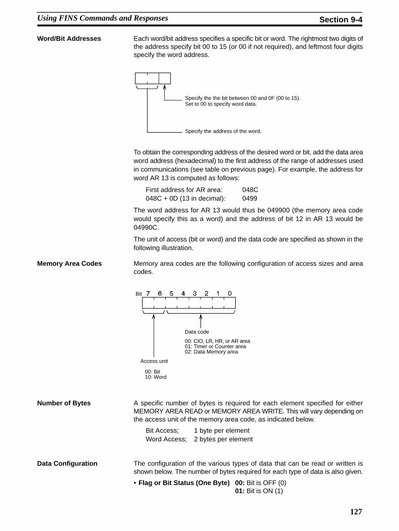
127
Word/Bit Addresses Each word/bit address specifies a specific bit or word. The rightmost two digits ofthe address specify bit 00 to 15 (or 00 if not required), and leftmost four digitsspecify the word address.
Specify the the bit between 00 and 0F (00 to 15).Set to 00 to specify word data.
Specify the address of the word.
To obtain the corresponding address of the desired word or bit, add the data areaword address (hexadecimal) to the first address of the range of addresses usedin communications (see table on previous page). For example, the address forword AR 13 is computed as follows:
First address for AR area: 048C048C + 0D (13 in decimal): 0499
The word address for AR 13 would thus be 049900 (the memory area codewould specify this as a word) and the address of bit 12 in AR 13 would be04990C.
The unit of access (bit or word) and the data code are specified as shown in thefollowing illustration.
Memory Area Codes Memory area codes are the following configuration of access sizes and areacodes.
00: Bit 10: Word
Access unit
Data code
00: CIO, LR, HR, or AR area 01: Timer or Counter area02: Data Memory area
Bit
Number of Bytes A specific number of bytes is required for each element specified for eitherMEMORY AREA READ or MEMORY AREA WRITE. This will vary depending onthe access unit of the memory area code, as indicated below.
Bit Access; 1 byte per elementWord Access; 2 bytes per element
Data Configuration The configuration of the various types of data that can be read or written isshown below. The number of bytes required for each type of data is also given.
• Flag or Bit Status (One Byte) 00: Bit is OFF (0)01: Bit is ON (1)
Using FINS Commands and Responses Section 9-4

128
• Word Contents or PV (Two Bytes)
Bits 0 to 7 (second byte)
Bits 8 to 15 (first byte)
Byte 1 Byte 2
9-5 Sample ProgramThis subsection provides a sample program for executing FINS commands andresponses.
9-5-1 Program Example
1, 2, 3... 1. The CMCR instruction is executed when the execution condition 00000turns ON while the Instruction Enabled Flag (bit 25204) is ON. Bit 12800stays ON from the time CMCR execution is started until it is completed.
2. The CMCR instruction’s control data and command data are set in advancein the C200HX/HG/HE’s memory area.
Control Data
Word Contents Meaning
D0000 $1810 Operating level #1
D0001 $0002 Number of bytes to send: 2 bytes
D0002 $0064 Number of bytes to receive: 100
D0003 $0001 Destination network address: $01
D0004 $0100 Destination node number: $01Destination unit address: $00 (PC)
D0005 $0000 Request responseNumber of retries: 0 (No retries)
D0006 $0000 Response monitor time: 2.2 s ($0000 is default)
Command Data
Word Contents Meaning
D0010 $0002 Data length: 2 words (BCD)
D0011 $0701 FINS command: CLOCK READ
3. Specifies the FINS response storage destination. In this example, the FINSresponse data is stored from DM 0020 onwards.
Sample Program Section 9-5

129
4. Executes the CMCR instruction.
5. CMCR instruction execution is completed when bit 12801 is turned ONwhile the Instruction Enabled Flag (bit 25204) is ON.
6. Turns ON if an error occurs during communications execution.
9-6 FINS Communications From ComputersCommands and responses sent from host computers must be in the formatsdescribed in this subsection and must provide the proper FINS header informa-tion. These formats can also be used to decode commands and responsesreceived from other network nodes.
9-6-1 Frame FormatWith the FINS communications service, datagrams in the Ethernet frame formatshown below are sent and received.
FINS header
Command code
Text
Ethernet header IP header UDP header FINS message
When a FINS command from a computer is used, the destination’s IP addressand UDP port number must be set.
9-6-2 FINS Command and Response FormatsThis subsection explains the data formats for FINS commands and responses.
FINS Commands Commands consist of a FINS header, command code, and text. The length andcontent of the text depend on the particular command.
FINS header Command code Text (max. 1,998 bytes)
FINS Responses A response block includes a response code (a 2-byte code in binary) added tothe command format. In the FINS header information, DNA DA1, and DA2 areinterchanged with SNA, SA1, and SA2 (in comparison to the command header)and SID is the same as that in the command header.
FINS header Commandcode
Text (max. 1,998 bytes)Responsecode
An error response will be returned if the IP-FINS node address conversion tableis not correctly set.
FINS Communications From Computers Section 9-6

130
9-6-3 FINS Header Information
This subsection explains the FINS header contents and settings used for FINScommands and responses.
ICF (Information Control Field)Information such as the data classification, response request, communicationsbetween networks, and so on, is set in the ICF. The configuration is as follows:
7 6 5 4 3 2 1 0
1 0 0 0 0 0
Response Request Bit (0: Request response; 1: Don’t request response)
Kind of data (0: command; 1: response)
RSV Reserved (system reserved area)
Set to $00.
GCNT (Permissible Number of Gateways)
Set to $02.
DNA (Destination Network Address)Specifies the network address of the destination node.
$01 to 7F: (1 to 127)
DA1 (Destination Node Number)Specifies the destination node number for sending the command. It is used forFINS, and is different from the IP address used for Ethernet.
$00: Local PC$01 to 7F (1 to 127): Node in Ethernet
DA2 (Destination Unit Address)Specifies as an absolute address a unit number at the destination node.(Example: CPU Special I/O Unit #0 is $10.)
$00: PC (CPU)$10 to $1F: CPU Special I/O Unit (PC Card Unit is $10.)$FE: Communications Unit
SNA (Source Network Address)
$01 to 7F: Local network address (1 to 127)
SA1 (Source Node Number)
$00: Local PC$01 to 7F (1 to 127): Node in Ethernet
SA2 (Source Node Address)
$00: PC (CPU)$10 to $1F: CPU Special I/O Unit (PC Card Unit is $10.)$FE: Communications Unit
SID (Service ID)The SID is used to identify the process that data is sent from. Set any desirednumber from $00 to $FF for the SID. The same number will be returned in theresponse, allowing you to match commands and responses in your application.
FINS Communications From Computers Section 9-6

131
9-6-4 Designating Remote AddressesUDP sockets are used when sending FINS commands from a host computer tothe C200/HX/HG/HE. This subsection provides an example of addressingremote PCs from the host computer for communications.
Host computerIP address: 196.36.32.50FINS network/node/unit: 1/32/0 hex)
Ethernet
PC Card Unit
Remote nodeIP address: 196.36.32.100FINS network/node/unit: 1/64/0 hex)
The communications parameters specified from the host computer would be asfollows:
Item Setting Remarks
Destination IP Address 196.36.32.100 PC Card Unit address
UDP port number 9600 (FINS UDP default portnumber)
PC Card Unit’s UDPport number
FINS addresses DNA, DA1, DA2 = 1, 64, 0 (hex) C200HX/HG/HE
SNA, SA1, SA2 = 1, 32, 0 (hex) Host computer
FINS Communications From Computers Section 9-6

133
SECTION 10Socket Services
This section describes sockets (an interface for directly using TCP and UDP functions from the user program) and explainshow to use socket services.
10-1 About Socket Services 134. . . . . . . . . . . . . . . . . . . . . . . . . . . . . . . . . . . . . . . . . . . . . . . . . . . . . 10-1-1 Sockets 134. . . . . . . . . . . . . . . . . . . . . . . . . . . . . . . . . . . . . . . . . . . . . . . . . . . . . . . . . . 10-1-2 Socket Operation 134. . . . . . . . . . . . . . . . . . . . . . . . . . . . . . . . . . . . . . . . . . . . . . . . . . 10-1-3 Differences between TCP and UDP 134. . . . . . . . . . . . . . . . . . . . . . . . . . . . . . . . . . . 10-1-4 Opening TCP Sockets 135. . . . . . . . . . . . . . . . . . . . . . . . . . . . . . . . . . . . . . . . . . . . . . 10-1-5 Socket Services Port Numbers 136. . . . . . . . . . . . . . . . . . . . . . . . . . . . . . . . . . . . . . . . 10-1-6 Fragmentation of Transmitted Data 136. . . . . . . . . . . . . . . . . . . . . . . . . . . . . . . . . . . .
10-2 Using Socket Services 138. . . . . . . . . . . . . . . . . . . . . . . . . . . . . . . . . . . . . . . . . . . . . . . . . . . . . 10-2-1 FINS Commands Used With Socket Services 138. . . . . . . . . . . . . . . . . . . . . . . . . . . . 10-2-2 Procedure for Using Socket Services 138. . . . . . . . . . . . . . . . . . . . . . . . . . . . . . . . . . 10-2-3 Socket Services and Socket Status 142. . . . . . . . . . . . . . . . . . . . . . . . . . . . . . . . . . . . . 10-2-4 Communications Timing Chart 143. . . . . . . . . . . . . . . . . . . . . . . . . . . . . . . . . . . . . . . 10-2-5 Socket Service Timing Chart 143. . . . . . . . . . . . . . . . . . . . . . . . . . . . . . . . . . . . . . . . . 10-2-6 Precautions in Using Socket Services 145. . . . . . . . . . . . . . . . . . . . . . . . . . . . . . . . . .
10-3 Sample Programs for TCP and UDP Communications 146. . . . . . . . . . . . . . . . . . . . . . . . . . . . 10-3-1 Ladder Programming for TCP/IP Communications 146. . . . . . . . . . . . . . . . . . . . . . . 10-3-2 Ladder Programming for UDP/IP Communications 154. . . . . . . . . . . . . . . . . . . . . . .

134
10-1 About Socket ServicesThis subsection provides an outline of PC Card Unit socket services.
10-1-1 SocketsA socket is an interface which allows a user program to directly use TCP (Trans-mission Control Protocol) and UDP (User Datagram Program).
Socket services allow arbitrary data to be sent to and from other nodes, therebyenabling communications in any protocol with FA computer other than OMRONPCs, with UNIX workstations, and so on.
Socket services are supplied for most host computers (or some personal com-puters) as a C-language interface library. This interface library allows user pro-grams to communicate using TCP and UDP.
The socket interface is supported for UNIX workstations in the form of systemcalls.
Socket services are achieved for C200HX/HG/HE PCs by sending FINS com-mands from the user program to a PC Card Unit. Refer to Section 9 FINS Com-mands, 10-2 Using Socket Services, 10-3 Sample Programs for TCP and UDPCommunications, and Section 11 FINS Commands and Responses.
10-1-2 Socket OperationA socket operates as shown in the following diagram when communicatingbetween an FA computer and a PC Card Unit. Data from the computer orC200HX/HG/HE PC passes through the socket and is communicated using theTCP or UDP protocol.
Pro
gram
Systemcall
IP
TCP
UDP
Soc
ket
TCP
UDP
TCP
UDP
Soc
ket
IP
Host computer
FINScommand
FINSresponse
CP
U
PC Card Unit C200HX/HG/HE
10-1-3 Differences between TCP and UDPThere are differences in the socket services between TCP and UDP.
TCP Communications The following procedure is followed each time data is transmitted to ensure thatthe data arrives properly at the destination node:
1, 2, 3... 1. The destination node returns ACK when data is received normally.
2. The local node sends the next data after it receives ACK, or it resends thesame data if ACK is not returned within the specified time.
Local node Transmitted data
ACK
Re-transmitted data
Destination node
About Socket Services Section 10-1

135
UDP Communications Data is simply sent to the destination. Unlike TCP, the receipt of data is notchecked and data is not re-transmitted. To increase communication reliability,data resends must be programmed by the user in user applications.
Local node Destination nodeTransmitted data
ACK (only when processed by application)
10-1-4 Opening TCP SocketsTo achieve highly reliable data communication, TCP establishes a virtual com-munications circuit between the two nodes before starting data transmissions.The virtual communications circuit is know as a “connection.”
An open command is executed for a node to establish a connection. The openmethod differs depending on whether the node is a client or server. A passiveopen method is used to open the node as a server and the active open method isused to open the node as a client.
ClientTCPsocket
Activeopen
Connection
Passiveopen
ServerTCPsocket
Client and Server When an application which includes data communications processing betweentwo nodes is executed, the node which provides the service is known as the“server” and the node which requests the service is known as the “client.” Theserver is booted first and waits for a service request from a client. Data is trans-mitted only after the client requests the server to establish a connection. If theTCP protocol is used, this process is carried out automatically at the protocollevel; it is not necessary to run an application program.
Note TCP communications with other TCP sockets will not be possible until the con-nection for the first socket opened has been closed. For the PC Card Unit, foursockets are provided for UDP and TCP together. Communications with multipleUDP sockets is possible, because connections are not set for UDP sockets.
Passive OPEN and ActiveOPEN
About Socket Services Section 10-1

136
The communications procedure is shown below for communications betweenan FA computer and PC Card Unit using a TCP socket.
FA computer(server)
Passive OPEN
PC Card Unit(client)
Connection requestActive OPEN
Establish connection
Transmitted dataSend data
Receive dataACK
Send next data
Establish connection Establish connection
Receive data
Send next data
Send data
Close Close
Transmitted data
ACK
10-1-5 Socket Services Port NumbersPort numbers up to 1023 on a UNIX workstation can be used by the superuseronly. Port numbers 0 to 255 are reserved for well-known ports. Consequently,port numbers from 1024 to 65535 should be used for socket services. The PCCard Unit does not support port #0.For FINS communications, the 9600 port is used as the default. Also, some portnumbers over 1024 may be reserved on some workstations (for example, theX-window server is port #6000). Do not use port numbers that are alreadyreserved for other processes.The setting status of the UNIX workstation port numbers can be checked in /etc/services.
10-1-6 Fragmentation of Transmitted DataThe PC Card Unit fragments data for TCP transmission into units of 1,024 bytesand data for UDP transmission into units of 1,472 bytes. TCP requires onereception request to receive each unit of data. UDP, however, restores the origi-nal data before passing it to the user process, allowing all the data in a singletransmission to be received with one reception request. Examples of these aregiven next.
Cautions when Using TCP An example of the fragmentation and transmission of data using the TCP isshown in the following illustration.
1, 2, 3... 1. The transmission user program sends a request to send 1,982 bytes of data.2. The PC Card Unit fragments the transmission data into Data A with 1,024
bytes and Data B with 958 bytes.3. Data A and Data B are sent consecutively.4. The receiving user program sends a request to receive 1,982 bytes of data.
However, only data A is sent in the first packet; data B is not received.
TCP CommunicationsProcedure
About Socket Services Section 10-1

137
5. Another receive request to receive data must be made before the remainingdata, Data B, is sent.
Data B
Transmissionuser program
PC Card Unit
1. Send request
Source data
1,982 bytes 1,024 bytesData A
Data B
958 bytes
Data A
Data B
Data A
2.
3.
Receive node Receiving user program
4. First receive request
1,982 bytes
1,982 bytes
958 bytes
5. Second receive request
1,024 bytes
When using TCP protocol, the fragmented data is passed to the user program.Therefore, the receiving user program must be able to evaluate the end of thedata transmission, and repeatedly send receive requests until all data has beenreceived. The receive request is sent twice in the example shown above, but thedata would be even more fragmented if a router were included in the commu-nications path, and the number of receive requests would need to be increasedaccordingly.When making the receive request, it is not necessary to specify the same datalength as the transmitted data length. For example, if the length setting is shorterthan the actual length of the data, all the data can be received by repeating thereceive requests.
When Using UDP An example of fragmentation and transmission of data using the UDP is shownin the following illustration.
1, 2, 3... 1. The transmission user program sends a request to send 1,982 bytes of data.2. The PC Card Unit fragments the transmission data into Data A with 1,472
bytes and Data B with 510 bytes.3. Data A and Data B are sent consecutively.4. When the receiving user program sends a request to receive 1,982 bytes of
data, Data A and Data B are linked to restore the original data which ispassed to the user program.
Source data
1,982 bytes
Transmissionuser program
1. Send request
Data A
Data B
1,472 bytes
510 bytes
PC Card Unit Receive node Receiving userprogram
4. First receive request1,982 bytes
Data A Data B
3.2.
As shown above, the UDP protocol handles data communications as data-grams, so that the transmitted data is restored to the original data before beingpassed to the user program. Consequently, if the data length in the receiverequest is set to the length of the transmitted data, the entire data can bereceived using a single receive data request.
About Socket Services Section 10-1

138
Note If the data length in the receive data request is erroneously set smaller than theactual length of the data, all received data exceeding the specified data lengthwill be discarded.
10-2 Using Socket Services
With the C200HX/HG/HE, socket services are controlled by FINS commands tothe PC Card Unit. For details regarding FINS commands and responses, refer toSection 9 FINS Commands.
10-2-1 FINS Commands Used With Socket Services
Socket services are executed by having the CMCR instruction executed in theC200HX/HG/HE program to issue a FINS command to the PC Card Unitrequesting socket services.
Set the FINS node address as follows: network to 0, node to 0, and Unit to $10.
PC Card Unit Other node
Transmission processingFINS commandrequestingsocket services
FINS responseto request
10-2-2 Procedure for Using Socket Services
The PC Card Unit has four sockets that can be used for TCP or UDP. Open,close, send, and receive processes are available for communications usingsockets.
OpenEnables communications on a specified socket. A socket must be openedbefore it can be used for socket services. Opening a TCP socket establishes aconnection.
CloseEnds use of the socket. Breaks the connection for a TCP socket.
SendSends data from a specified open socket.
ReceiveSpecifies an open socket and receives data from that socket.
These processes are carried out by using the CMCR instruction to send FINScommands to the PC Card Unit. The process from sending a request for proces-sing to completion is shown in the following illustrations.
Using Socket Services Section 10-2

139
1, 2, 3... 1. Use CMCR to issue a socket service request command (MRC: 27) to the PCCard Unit.
CPU
User program
PC Card Unit
CMCR
END
FINS commandrequestingsocket services
2. CMCR ends normally when the socket service request command isreceived and a response is returned (response code: 0000).
PC Card Unit
Response
CPU
User program
CMCR
END
3. The PC Card Unit starts the process requested by the parameters in thesocket service request command.
CPU PC Card Unit
CommunicationsOther node
4. When the process has been completed, the result is stored in the resultsstorage area defined in the socket service request command and the socketstatus will indicate completion of processing.
The socket status area is in AR words 08 to 15. The result storage area isspecified by the FINS command.
CPU
Socket status area
Results storage area
PC Card Unit
Process completenotification
Result stored
Using Socket Services Section 10-2

140
Socket Service Request Commands
Commandcode
Name Description Page
MRC SRC27 01 UDP OPEN REQUEST Opens the UDP socket. 187
02 UDP RECEIVE REQUEST Receives data at the UDP socket. 188
03 UDP SEND REQUEST Sends data from the UDP socket. 189
04 UDP CLOSE REQUEST Closes the UDP socket and ends communications. 190
10 TCP OPEN REQUEST (PASSIVE) Opens a TCP socket and waits for connection to anothernode.
191
11 TCP OPEN REQUEST (ACTIVE) Opens a TCP socket and connects to another node. 192
12 TCP RECEIVE REQUEST Receives data at the TCP socket. 193
13 TCP SEND REQUEST Sends data from the TCP socket. 194
14 TCP CLOSE REQUEST Closes the TCP socket and ends communications. 195
The basic format for FINS commands used for socket services is shown in thefollowing diagram.
Socketnumber
0 1 2 3 4 5 6 7 8 9 10 11 12
Commandcode
Results storage area Parameters
Command Code:Specifies the process code requested for the socket.
Socket NumberSpecifies the socket number for the process, between 1 and 4.
Results Storage AreaSpecifies the area to store the results of the requested process.
ParametersSpecifies the parameters defined for the command code.
Refer to Section 11 FINS Commands and Responses for details about com-mands.
Socket Status Area Each PC Card Unit has four sockets that can be used for TCP or UDP. The statusof each of these sockets can be confirmed from the by AR bits.
AR Words 08 to 15
Byte
Operating level #0, socket no. 1 status area
Operating level #0, socket no. 2 status area
Operating level #0, socket no. 3 status area
Operating level #0, socket no. 4 status area
Operating level #1, socket no. 1 status area
Operating level #1, socket no. 2 status area
Operating level #1, socket no. 3 status area
Operating level #1, socket no. 4 status area
Basic FINS CommandFormat
Using Socket Services Section 10-2

141
Bit Configuration The meaning of individual bits in each status word is shown in the following dia-gram.
Bit
Open Flag
Results Storage Error Flag
Socket Classification Flag Closing Flag
Sending Flag
Receiving Flag
Opening Flag
Bit Flag Value Status DescriptionBit 0 Opening Flag 1 Opening ON when an open request is received.
0 Open complete OFF when opening has been completed.
Bit 1 Receiving Flag 1 Receiving ON when a receive request is received.
0 Receive complete OFF when receive has been completed.
Bit 2 Sending Flag 1 Sending ON when a send request is received.
0 Send complete OFF when send has been completed.
Bit 3 Closing Flag 1 Closing ON when a close request is received.
0 Close complete OFF when close has been completed.
Bit 4 to 12 Not used
Bit 13 SocketClassification
1 TCP socket Indicates that the open socket is a TCP socket.(This has no meaning if the Open Flag is “0.”)
Flag 0 UDP socket Indicates that the open socket is a UDP socket.(This has no meaning if the Open Flag is “0.”)
Bit 14 Results StorageError Flag
1 Results storageerror
ON when the results storage area is incorrectlydefined for a FINS command sent to a PC CardUnit. This flag will not turn ON until the Opening,Receiving, Sending, and Closing Flags turn OFF.
0 Results storagenormal
OFF when the next service is requested at thesocket.
Bit 15 Open Flag 1 Open (connected) ON when opening has been completed. This flagindicates the TCP socket is connected.
0 Closed OFF when closing has been completed. RemainsOFF if an error occurs during opening.
Using Socket Services Section 10-2

142
10-2-3 Socket Services and Socket StatusWhen using socket services, it is important to consider the timing of the statuschanges in the socket status area. The diagram below shows a program flow-chart for opening UDP.
Program flow is similar for other socket services. Replace the names of theappropriate flags in the flowchart to adapt it to other socket services.
An error occurred. The PC CardUnit did not receive the UDPOPEN REQUEST command.
Check socket status.
Start UDP Open
OFF?
OFF
The specified UDP socket isalready open.
Program Flow
Is Bit 15 (Open Flag) in the socket status word forthe socket being used OFF? (Checks to see if the socket is open before com-munications and close processing.)
YES
Error Evaluation
Check the Instruction Enabled Flag.
Execute FINS command (via CMCR) for PC Card Unit.
Check response.
Check Opening Flag status.
Check results storage area response code.
ON? The specified port is runningnetwork communications.
Is the appropriate bit in word 252 for the operatinglevel being used ON?
YES
Use the CMCR to send the UDP OPEN REQUEST com-mand (2701) to the PC Card Unit.
Is the response code = 0000 (normal) for theUDP OPEN REQUEST command?
Wait until bit 00 in the socket status turns OFF(open complete).
Is response code = 0000?
0000?
YES
0000?
YES
UDP opened
(Socket status bit 00)
An error occurred. The specifiedsocket could not be opened.
NO
NO
NO
NO
Using Socket Services Section 10-2

143
10-2-4 Communications Timing ChartThe timing of the status changes of the bits in the socket status area and theInstruction Enabled Flag is shown in the following diagram.
10
1010
1010
Instruction Enabled Flag
Opening Flag
Receiving Flag
Sending Flag
Closing Flag
Open flag
10
10
Open requestreceived
Open complete
Receive requestreceived
Receive complete
Send requestreceived
Send complete
Close requestreceived
Close complete
10-2-5 Socket Service Timing ChartThe timing of the socket service open, send, receive and close request com-mands are shown in the following diagrams.
OPEN REQUEST10
10
10
Instruction Enabled Flag
CMCR response code
Opening Flag
Open Flag
Results storage area
Running Running
Error response code Normal response code
OPEN REQUESTcommand received
Errorend
OPEN REQUESTcommand received
Normalend
Open complete(normal end)
Store normal response code
CLOSE REQUEST10
10
10
Instruction Enabled Flag
CMCR response code
Closing Flag
Close Flag
Results storage area
Running Running
Error response code Normal response code
Store normal response code
CLOSE REQUESTcommand received
CLOSE REQUESTcommand received
Errorend
Normalend
Close complete(normal end)
Using Socket Services Section 10-2

144
SEND REQUEST
10
10
10
Running Running
Error response code Normal response code
Errorend
Instruction Enabled Flag
CMCR response code
Sending Flag
Open Flag
Results storage area
SEND REQUESTcommand received
Send complete(normal end)
SEND REQUESTcommand received
Store normal response code
RECEIVE REQUEST
10
10
10
Running Running
Error response code Normal response code
Errorend
Instruction Enabled Flag
CMCR response code
Receiving Flag
Open Flag
Results storage area
RECEIVE REQUESTcommand received
RECEIVE REQUESTcommand received
Receive complete(normal end)
Store normal response code
CLOSE REQUEST during RECEIVE REQUEST
10
10
10
10
Instruction Enabled Flag
RECEIVE REQUEST command received CLOSE REQUEST command received
Running Running
Normal response code
Results storage area forRECEIVE REQUEST
Normal response code
CMCR (RECEIVE REQUEST)response code
CMCR (CLOSE REQUEST)response code
Receiving Flag
Open Flag
Closing Flag
Results storage area forCLOSE REQUEST
Store error response code
Store normal response code
Note The timing shown in the above diagram occurs if a CLOSE REQUEST com-mand is executed during SEND REQUEST command execution. The timing
Using Socket Services Section 10-2

145
shown in the diagram also applies if a CLOSE REQUEST command is executedduring OPEN REQUEST command execution, with the exception of the statusof the Open Flag.
10-2-6 Precautions in Using Socket Services• If a short response monitor time is specified in the CMCR control data and the
PC Card Unit is operating under a high load, a result may be stored even if theresponse code indicates a time-out. If this occurs, increase the monitor timespecified with CMCR.
• If the Results Storage Error Flag turns ON in socket status, it indicates that thespecified results storage area does not exist in the C200HX/HG/HE. Correctthe user program.
• Communications processing may be slowed down by multiple simultaneoususage of PC Card Unit functions, or by the contents of the user program.
• Communications efficiency may decrease due to high communications loadson the network.
• All data is flushed from the socket’s communications buffer when a socket isclosed with the CLOSE REQUEST command. In some cases, the transmitdata for the SEND REQUEST command issued just before the socket wasclosed may not be sent.
• When sockets are open, the PC Card Unit internally provides 64 bytes ofreceive buffers to allow data to be received at any time. These buffers areshared by all open sockets. Socket service communications are interrupted ifall these buffers become full. The user application must therefore issueRECEIVE REQUEST commands frequently enough to prevent the internalbuffers from becoming full.
• With the UDP socket, data can be broadcasted to all nodes of the networksimultaneously by setting a broadcast address for the destination nodeaddress. The maximum length of broadcast data is 1,472 bytes. Data in multi-ple fragments (over 1,472 bytes for a UDP socket) cannot be broadcast.
• The UDP socket does not check the transmitted data to ensure communica-tions reliability. To increase communication reliability, communications checksand retries must be included in the user application program.
• If the TCP socket of the remote node is closed (the connection is broken) dur-ing communications, the TCP socket at the local node must also be closed.The communications results storage areas can be used to check if the connec-tion has been broken. Close the local socket immediately after detecting thatthe remote TCP socket has closed. The following situations indicate that theremote socket has closed.
TCP receive results storage area: response code = 0000 (normal), numberof bytes received = 0000
TCP send results storage area: response code = 0081 (specified socketclosed during transmission)
• After closing the port of a connected TCP/IP socket, the port cannot be usedwithin 60 seconds of being closed. However, this restriction does not apply fora port opened using the TCP OPEN REQUEST (ACTIVE) command with alocal TCP port number of 0 (port number automatically assigned) which isclosed from the side that actively opened the socket.
• A connection is established for a passively opened socket by actively openingit from another socket. A connection will not be established for an activelyopened socket even if the active open command is executed from anothersocket. Moreover, you cannot actively open multiple connections to a socketpassively opened at the PC Card Unit.
UDP and TCP SocketServices
UDP Socket Services Only
TCP Socket Services Only
Using Socket Services Section 10-2

146
10-3 Sample Programs for TCP and UDP CommunicationsThis subsection provides sample programs for TCP/IP communications andUDP/IP communications.
10-3-1 Ladder Programming for TCP/IP CommunicationsThe following program example sends and receives 100 bytes of data betweenthe PC Card Unit and the computer using TCP/IP communications. The systemand data area applications are described before the program example anddetails of program operation are described following each section of the exam-ple.
System ConfigurationThe system configuration for the program example and the PC Card Unit systemsetup are shown below. To establish a TCP connection in this example, the PCCard Unit is passively opened and the computer is actively opened.
Computer
IP address: 196.36.32.55, Port #4096 Operating level #1IP address: 196.36.32.101
FINS Network address: $01Node number: $01Unit address: $10
PC Card Unit
C200HX/HG/HE PC
CMCR Data Flow to the PC Card UnitThe data flow for sending CMCR instructions to the PC Card Unit is shown in thefollowing diagram.
Computer Ethernet network PC Card Unit
4. Send to network
5. Computerprocessing
C200HX/HG/HE
1. CMCR issued
2. Work bits turned ON
3. CMCR response
6. Results stored in resultsstorage area
7. Work bits turned OFF
Note These work bits (CIO 00000 to CIO 00003) are set by the program to controlCMCR execution and are not system flags, such as the Instruction Enabled Flag(25204).
Data Area ApplicationThe data area words and bits used in the communications program are allocatedas shown in the following diagrams. These words and bits are used for CMCRcontrol data, command data, and results storage.
Sample Programs for TCP and UDP Communications Section 10-3

147
Example The following diagrams indicate that DM 0000 is the first word used in CMCR fora TCP OPEN REQUEST and it contains 1810hex, that DM 00001 contains0012hex, that CIO 00000 is used to control TCP open processing, and thatCIO 0001 is used to control TCP close processing.
How to Read TablesDM Area
CIO Area
$1810 $0012
0 1 2 3 4 5 6 7 8 9
DM 0000 CMCR control data for TCP OPEN REQUEST (PASSIVE)
7 6 5 4 3 2 1 0
CIO 000
15 to 8
TCPclose bit
TCPopen bit
Memory Map for Sample Programs
$1810 $0012 $0004 $0001 $0110 $0000
0 1 2 3 4 5 6 7 8 9
DM 0000 CMCR control data for TCP OPEN REQUEST (PASSIVE)
DM Area
$0032
CMCR timeout value
PC Card Unit address (Matchenvironment of PC being used.)Network address: $01Node number: $01Unit address: $10
Number of retries
Number of response bytes to receive: 4 bytesNumber of bytes to send: 18
Operating level #1 (or $0810 of operating level #0)
$1810 $0008 $0004 $0001 $0110 $0000
0 1 2 3 4 5 6 7 8 9
DM 0010 CMCR control data for TCP CLOSE REQUEST
Number of bytes to send: 8 bytesNumber of response bytes to receive: 4 bytes
$0032
Number of response bytes to receive: 4 bytes
$1810 $006E $0004 $0001 $0110 $0000
0 1 2 3 4 5 6 7 8 9
DM 0020 CMCR control data for TCP SEND REQUEST
Number of bytes to send: 110 bytesCommand format = 10 bytes + 100 bytes transmission data
$0032
Number of response bytes to receive: 4 bytes
$1810 $000C $0004 $0001 $0110 $0000
0 1 2 3 4 5 6 7 8 9
DM 0030 CMCR control data for TCP RECEIVE REQUEST
Number of bytes to send: 12 bytesNumber of bytes received specified in command data.
$0032
Sample Programs for TCP and UDP Communications Section 10-3

148
$0010 $2710 $0001 $8203 $FC00 $1000
0 1 2 3 4 5 6 7 8 9
DM 1000
$0000 $C424 $2037
TCP OPEN REQUEST (PASSIVE) command data
$0000
Remote port number: Not specifiedComputer IP address: 196.36.32.55($C4, $24, $20, $37)
Timeout value: Not setLocal port number: set to 4096 ($1000)
Results storage area: set to DM 1020 ($03FC)TCP socket number (PC Card Unit socket number): set to 1
Command codeTransmission data length: 10 words (BCD)
$2710
0 1 2 3 4 5 6 7 8 9
DM 1010Responsecode
TCP OPEN REQUEST (PASSIVE) response
Stores the response after CMCR command execution.
0 1 2 3 4 5 6 7 8 9
DM 1020TCP OPEN REQUEST (PASSIVE) results storage area
Responsecode Remote IP
addressRemoteTCP portnumber
$0005 $2714 $0001 $8204
0 1 2 3 4 5 6 7 8 9
DM 1030 TCP CLOSE REQUEST command data
$1A00
Results storage area: set to DM 1050 ($041A)TCP socket number to close: set to 1
Command codeTransmission data length: 5 words (BCD)
$0056 $2713 $0001 $820B
0 1 2 3 4 5 6 7 8 9
DM 2000
$2714
0 1 2 3 4 5 6 7 8 9
DM 1040
DM 1050
$C200
TCP CLOSE REQUEST responseResponsecode
Responsecode
TCP CLOSE REQUEST results storage area
TCP SEND REQUEST command data
Send data: 100 bytes$0064
Number of bytes to send: set to 100 bytes ($0064)Results storage area: set to DM 3010 ($0BC2)
Socket number to use: set to 1Command code
Transmission data length: 56 words (BCD)
Sample Programs for TCP and UDP Communications Section 10-3

149
$0007 $2712 $0001 $820F
0 1 2 3 4 5 6 7 8 9
DM 4000
$2713
0 1 2 3 4 5 6 7 8 9
DM 3000
DM3010
$B400 $0064
TCP SEND REQUEST responseResponsecode
Responsecode
TCP SEND REQUEST results storage areaNo. ofbytessent
TCP RECEIVE REQUEST command data
$0000
Timeout value: Not setNo. of bytes to receive: 100 bytes ($0064)
Results storage area: Set to DM 4020 ($0FB4)Socket number to use: set to 1
Command codeTransmission data length: 7 words (BCD)
$2712
0 1 2 3 4 5 6 7 8 9
DM 4010
DM 4020
TCP RECEIVE REQUEST responseResponsecode
Responsecode
TCP RECEIVE REQUEST results storage areaNo. ofbytesreceived
Send data: 100 bytes
7 6 5 4 3 2 1 0
CIO 000
CIO 001
15 to 8
CIO 002
TCPsend bit
TCPclose bit
TCPopen bit
TCPreceiveerrorbit
TCPsenderrorbit
TCPcloseerrorbit
TCPopenerrorbit
TCPreceivework bit
TCPsendwork bit
TCPcloseworkbit
TCPopenwork bit
TCPreceivebit
CIO Area
Sample Programs for TCP and UDP Communications Section 10-3

150
Program Example 1
TCP open bit
TCP open bit TCP open work bit InstructionEnabled Flag
TCP open bit TCP open work bit InstructionEnabled Flag
TCP Opening Flag Results Storage Error Flag
Equals Flag
TCP open bit TCP open work bit InstructionEnabled Flag
TCP Opening Flag
TCP close bit
TCP close bit TCP close work bit InstructionEnabled Flag
TCP close bit TCP close work bit InstructionEnabled Flag
TCP Closing Flag Results Storage Error Flag
Equals Flag
TCP open bit TCP close work bit InstructionEnabled Flag
TCP Closing Flag
TCP openerror bit
TCP openwork bit
TCP openwork bit
ResultsStorage Area
TCPopen bit
TCP closeerror bit
TCP closework bit
TCP openwork bit
TCPclose bit
TCP closeerror bit
ResultsStorage Area
TCP closework bit
Sample Programs for TCP and UDP Communications Section 10-3

151
Explanation of Ladder ProgramThe first section of the program uses CMCR to execute TCP PASSIVE OPEN.Program execution starts when CIO 00000 turns ON.
Programaddress
Explanation
00000 Starting TCP OPEN execution.
When CIO 00000 turns ON, the TCP open error bit (CIO 00100) turnsOFF and the TCP open work bit (CIO 00200) turns ON to request oneexecution of TCP OPEN.
00005 Execution of the TCP OPEN REQUEST via CMCR
If the Instruction Enabled Flag (25204) is ON while the TCP open workbit (CIO 00200) is ON, a TCP OPEN REQUEST is executed via CMCRand the TCP open work bit (CIO 00200) is turned OFF. Executionpauses until CMCR instruction execution has been completed.
00010 Error evaluation.
The Instruction Enabled Flag (25204) turns ON again and the TCPOpening Flag (CIO A1200) turns OFF to indicate that execution of TCPOPEN via CMCR has ended. The Results Storage Error Flag(CIO A1214) and the response code in the results storage area (DM1020) are checked and the TCP open error bit (CIO 00100) turns ON ifan error has occurred.
00024 End of TCP OPEN execution.
CIO 00000 turns OFF to indicate that execution has been completed.
The next section of program uses CMCR to execute TCP CLOSE. Executionstarts when CIO 00001 turns ON
Programaddress
Explanation
00029 Starting TCP CLOSE execution.
When CIO 00001 turns ON, the TCP close error bit (CIO 00100) turnsOFF and the TCP close bit (CIO 00201) turns ON to request oneexecution of TCP CLOSE.
00034 Execution of the TCP CLOSE via CMCR.
If the Instruction Enabled Flag (25204) is ON while the TCP close workbit (CIO 00201) is ON, TCP CLOSE is executed via CMCR and theTCP close work bit (CIO 00201) turns OFF. Execution pauses until theCMCR instruction has been completed.
00039 Error evaluation.
The Instruction Enabled Flag (25204) turns ON again and the TCPclosing bit (CIO A1203) turns OFF to indicate that execution of TCPCLOSE via CMCR has ended. The Results Storage Error Flag(CIO A1214) and the response code in the results storage area (DM1050) are checked and the TCP close error bit (CIO 00101) turns ON ifan error has occurred.
00053 End of TCP CLOSE execution.
CIO 00001 turns OFF to indicate that execution has been completed.
Sample Programs for TCP and UDP Communications Section 10-3

152
Program Example 2
TCP send bit
TCP send bit TCP send work bit InstructionEnabled Flag
TCP send bit TCP send work bit InstructionEnabled Flag
TCP Sending Flag Results Storage Error Flag
Equals Flag
TCP send bit TCP send work bit InstructionEnabled Flag
TCP Sending Flag
TCP receive bit
TCP receive bit TCP receive work bit InstructionEnabled Flag
TCP receive bit TCP receive work bit InstructionEnabled Flag
TCP Receiving FlagResults Storage Error Flag
Equals Flag
TCP receive bit TCP receive work bit InstructionEnabled Flag
TCP Receiving Flag
TCP senderror bit
TCP sendwork bit
TCP sendwork bit
Resultsstorage area
TCP senderror bit
TCPsend bit
TCP receiveerror bit
TCP receivework bit
TCP receivework bit
Resultsstorage area
TCP receiveerror bit
TCPreceive bit
Sample Programs for TCP and UDP Communications Section 10-3

153
Explanation of Ladder ProgramThe next section of program uses CMCR to execute TCP SEND. Executionstarts when CIO 00002 turns ON.
Programaddress
Explanation
00053 Starting TCP SEND execution.
When CIO 00002 turns ON, the TCP send error bit (CIO 00102) turnsOFF and the TCP send work bit (CIO 00202) turns ON to request oneexecution of TCP SEND.
00063 Execution of the TCP SEND via CMCR.
If the Instruction Enabled Flag (25204) is ON while the TCP send workbit (CIO 00202) is ON, TCP SEND is executed via CMCR and the TCPsend work bit (CIO 00202) turns OFF. Execution pauses until the CMCRinstruction has been completed.
00068 Error evaluation.
The Instruction Enabled Flag (25204) turns ON again and the TCPSending Flag (CIO A1202) turns OFF to indicate that TCP SENDexecution via CMCR has ended. The Results Storage Error Flag(CIO A1214) and the response code in the results storage area(DM 4020) are checked and the TCP send error bit (CIO 00102) isturned ON if an error has occurred.
00082 End of TCP SEND execution.
CIO 00002 turns OFF to indicate that the instruction execution has beencompleted.
The next section of program uses CMCR to execute TCP RECEIVE. Executionstarts when CIO 00003 turns ON.
Programaddress
Explanation
00087 Starting TCP RECEIVE execution.
When CIO 00003 turns ON, the TCP receive error bit (CIO 00103) turnsOFF and the TCP receive work bit (CIO 00203) turns ON to request oneexecution of TCP RECEIVE.
00092 Execution of the TCP RECEIVE via CMCR.
If the Instruction Enabled Flag (25204) is ON while the TCP receivework bit (CIO 00203) is ON, TCP RECEIVE is executed via CMCR andthe TCP receive work bit (CIO 00203) turns OFF. Execution pauses untilthe CMCR instruction has been completed.
00097 Error evaluation.
The Instruction Enabled Flag (25204) turns ON again and the TCPReceiving Flag (CIO A1201) turns OFF to indicate that execution ofTCP RECEIVE via CMCR has ended. The Results Storage Error Flag(CIO A1214) and the response code in the results storage area(DM 4020) are checked and the TCP receive error bit (CIO 00103) isturned ON if an error has occurred.
00111 End of TCP RECEIVE execution.
CIO 00003 turns OFF to indicate that execution has been completed.
Sample Programs for TCP and UDP Communications Section 10-3

154
10-3-2 Ladder Programming for UDP/IP Communications
The following program example sends and receives 100 bytes of data betweenthe PC Card Unit and the host computer using UDP/IP communications. Thesystem and data area applications are described before the program exampleand details of program operation are described following each section of theexample.
System ConfigurationThe system configuration for the program example and the PC Card Unit systemsetup are shown below. For purposes of this example, the network settings forthe PC Card Unit and the computer are as shown in the diagram.
Computer
IP address: 196.36.32.55, Port #4096 Operating level #1IP address: 196.36.32.101
FINS network address: $01Node number: $01Unit address: $10
PC Card Unit
C200HX/HG/HE PC
Explanation of OperationUDP OPEN REQUEST is executed for the PC Card Unit when CIO 00000 turnsON. UDP CLOSE REQUEST is executed for the PC Card Unit when CIO 00001turns ON. UDP SEND REQUEST is executed for the PC Card Unit when CIO00002 turns ON and 100 bytes of data are sent beginning with DM 2009. UDPRECEIVE REQUEST is executed for the PC Card Unit when CIO 00003 turnsON and 100 bytes of data are received and stored beginning with DM 4025.
The appropriate bit in CIO 0001 turns ON when an error occurs. The followingareas can be used to access details about errors:
CMCR response codesResponse codes in results storage area
Data Area ApplicationThe data area words and bits used in the communications program are allocatedas shown in the following diagrams. These words and bits are used for CMCRcontrol data, command data, and results storage.
Example The following diagrams indicate that DM 0000 is the first word used in CMCR fora UDP OPEN REQUEST and it contains 1810hex, that DM 0001 contains000Ahex, that CIO 00000 is used to control UDP open processing, and thatCIO 00001 is used to control UDP close processing.
Sample Programs for TCP and UDP Communications Section 10-3

155
How to Read Tables
$1810 $000A
0 1 2 3 4 5 6 7 8 9
DM 0000 CMCR control data for UDP OPEN REQUEST (PASSIVE)
7 6 5 4 3 2 1 0
CIO 000
15 to 8
UDPclose bit
UDPopen bit
DM Area
CIO Area
Memory Map for Sample Programs
$1810 $000A $0004 $0001 $0110 $0000
0 1 2 3 4 5 6 7 8 9
DM 0000 CMCR control data for UDP OPEN REQUEST (PASSIVE)
DM Area
$0032
CMCR timeout value: 5 s
Destination PC Card Unit designationNetwork address: $01Node number: $01Unit address: $10
Number of retries
Number bytes to receive: 4 bytesNumber of bytes to send: 10
Operating level #1 (or $0810 for operating level #0)
$1810 $0008 $0004 $0001 $0110 $0000
0 1 2 3 4 5 6 7 8 9
DM 0010 CMCR control data for UDP CLOSE REQUEST
Number of bytes to send: 8 bytesNumber bytes to receive: 4 bytes
$0032
Number bytes to receive: 4 bytes
$1810 $0074 $0004 $0001 $0110 $0000
0 1 2 3 4 5 6 7 8 9
DM 0020 CMCR control data for UDP SEND REQUEST
Number of bytes to send: 116 bytesCommand format = 16 bytes + 100 bytes transmission data
$0032
Number bytes to receive: 4 bytes
$1810 $000C $0004 $0001 $0110 $0000
0 1 2 3 4 5 6 7 8 9
DM 0030 CMCR control data for UDP RECEIVE REQUEST
Number of bytes to send: 12 bytesNumber of bytes received specified in command data.
$0032
Sample Programs for TCP and UDP Communications Section 10-3
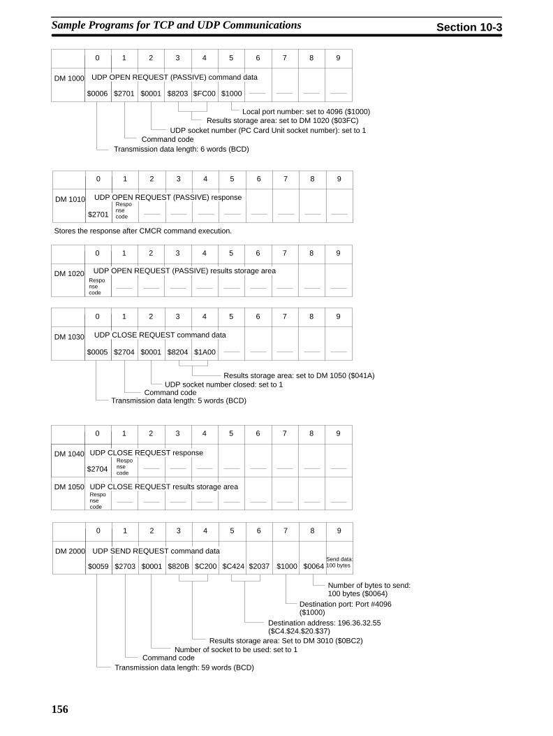
156
$0006 $2701 $0001 $8203 $FC00 $1000
0 1 2 3 4 5 6 7 8 9
DM 1000 UDP OPEN REQUEST (PASSIVE) command data
Local port number: set to 4096 ($1000)Results storage area: set to DM 1020 ($03FC)
UDP socket number (PC Card Unit socket number): set to 1Command code
Transmission data length: 6 words (BCD)
$2701
0 1 2 3 4 5 6 7 8 9
DM 1010Responsecode
UDP OPEN REQUEST (PASSIVE) response
Stores the response after CMCR command execution.
0 1 2 3 4 5 6 7 8 9
DM 1020 UDP OPEN REQUEST (PASSIVE) results storage areaResponsecode
$0005 $2704 $0001 $8204
0 1 2 3 4 5 6 7 8 9
DM 1030 UDP CLOSE REQUEST command data
$1A00
Results storage area: set to DM 1050 ($041A)UDP socket number closed: set to 1
Command codeTransmission data length: 5 words (BCD)
$0059 $2703 $0001 $820B
0 1 2 3 4 5 6 7 8 9
DM 2000
$2704
0 1 2 3 4 5 6 7 8 9
DM 1040
DM 1050
$C200
UDP CLOSE REQUEST responseResponsecode
Responsecode
UDP CLOSE REQUEST results storage area
UDP SEND REQUEST command data
$C424 $2037 $1000 $0064Send data:100 bytes
Number of bytes to send:100 bytes ($0064)
Destination port: Port #4096($1000)
Destination address: 196.36.32.55($C4.$24.$20.$37)
Results storage area: Set to DM 3010 ($0BC2)Number of socket to be used: set to 1
Command codeTransmission data length: 59 words (BCD)
Sample Programs for TCP and UDP Communications Section 10-3

157
$0007 $2702 $0001 $820F
0 1 2 3 4 5 6 7 8 9
DM 4000
$2703
0 1 2 3 4 5 6 7 8 9
DM 3000
DM 3010
$B400 $0064
UDP SEND REQUEST responseResponsecode
Responsecode
UDP SEND REQUEST results storage areaNo. ofbytessent
UDP RECEIVE REQUEST command data
$0000
Timeout value: Not setNo. of bytes to receive: 100 bytes ($0064)
Results storage area: set to DM 4020 ($0FB4)Number of socket to be used: set to 1
Command codeTransmission data length: 7 words (BCD)
$2702
0 1 2 3 4 5 6 7 8 9
DM 4010
DM 4020
UDP RECEIVE REQUEST responseResponsecode
Responsecode
UDP RECEIVE REQUEST results storage area
Send data: 100 bytesSource IPaddress
Sourceportnumber
No. ofbytes toreceive
7 6 5 4 3 2 1 0
CIO 000
CIO 001
15 to 8
CIO 002
UDPsend bit
UDPclose bit
UDPopen bit
UDPreceiveerrorbit
UDPsenderrorbit
UDPcloseerrorbit
UDPopenerrorbit
UDPreceivework bit
UDPsendwork bit
UDPcloseworkbit
UDPopenwork bit
UDPreceivebit
CIO Area
Sample Programs for TCP and UDP Communications Section 10-3

158
Program Example 3
UDP open bit
UDP open bit UDP open work bit InstructionEnabled Flag
UDP open bit UDP open work bit InstructionEnabled Flag
UDP Opening Flag Results Storage Error Flag
Equals Flag
UDP open bit UDP open work bit InstructionEnabled Flag
UDP Opening Flag
UDP close bit
UDP close bit UDP close work bit InstructionEnabled Flag
UDP close bit UDP close work bit InstructionEnabled Flag
UDP Closing Flag Results Storage Error Flag
Equals Flag
UDP open bit UDP close work bit InstructionEnabled Flag
UDP Closing Flag
UDPclose bit
UDP closeerror bit
Resultsstorage area
UDP closework bit
UDP closeerror bit
UDP closework bit
UDPopen bit
UDP openwork bit
Resultsstorage area
UDP openwork bit
UDP openwork bit
UDP openerror bit
Sample Programs for TCP and UDP Communications Section 10-3

159
Explanation of Ladder ProgramThe first section of program uses CMCR to execute UDP PASSIVE OPEN. Pro-gram execution starts when CIO 00000 turns ON.
Programaddress
Explanation
00000 Starting UDP OPEN execution.
When CIO 00000 turns ON, the UDP open error bit (CIO 00100) turnsOFF and the UDP open work bit (CIO 00200) turns ON to request oneexecution of UDP OPEN.
00005 Execution of the UDP OPEN REQUEST via CMCR
If the Instruction Enabled Flag (25204) is ON while the UDP open workbit (CIO 00200) is ON, a UDP OPEN REQUEST is executed via CMCRand the UDP open work bit (CIO 00200) is turned OFF. Executionpauses until CMCR instruction execution has been completed.
00010 Error evaluation.
The Instruction Enabled Flag (25204) turns ON again and the UDPOpening Flag (CIO A1200) turns OFF to indicate that execution of UDPOPEN via CMCR has ended. The Results Storage Error Flag(CIO A1214) and the response code in the results storage area (D1020)are checked and the UDP open error bit (CIO 00100) turns ON if anerror has occurred.
00024 End of UDP OPEN execution.
CIO 00000 turns OFF to indicate that execution has been completed.
The next section of program uses CMCR to execute UDP CLOSE. Executionstarts when CIO 00001 turns ON.
Programaddress
Explanation
00029 Starting UDP CLOSE execution.
When CIO 00001 turns ON, the UDP close error bit (CIO 00100) turnsOFF and the UDP close bit (CIO 00201) turns ON to request oneexecution of UDP CLOSE.
00034 Execution of the UDP CLOSE via CMCR.
If the Instruction Enabled Flag (25204) is ON while the UDP close workbit (CIO 00201) is ON, UDP CLOSE is executed via CMCR and theUDP close work bit (CIO 00201) turns OFF. Execution pauses until theCMCR instruction has been completed.
00039 Error evaluation.
The Instruction Enabled Flag (25204) turns ON again and the UDPclosing bit (CIO A1203) turns OFF to indicate that execution of UDPCLOSE via CMCR has ended. The Results Storage Error Flag(CIO A1214) and the response code in the results storage area (D1050)are checked and the UDP close error bit (CIO 00101) turns ON if anerror has occurred.
00053 End of UDP CLOSE execution.
CIO 00001 turns OFF to indicate that execution has been completed.
Sample Programs for TCP and UDP Communications Section 10-3

160
Program Example 4
UDP send bit
UDP send bit UDP send work bit InstructionEnabled Flag
UDP send bit UDP send work bit InstructionEnabled Flag
UDP Sending Flag Results Storage Error Flag
Equals Flag
UDP send bit UDP send work bit InstructionEnabled Flag
UDP Sending Flag
UDP receive bit
UDP receive bit UDP receive work bit InstructionEnabled Flag
UDP receive bit UDP receive work bit InstructionEnabled Flag
UDP Receiving Flag Results Storage Error Flag
Equals Flag
UDP receive bit UDP receive work bit InstructionEnabled Flag
UDP Receiving Flag
UDP senderror bit
UDP sendwork bit
UDP sendwork bit
Resultsstorage area
UDP senderror bit
UDPsend bit
UDP receiveerror bit
UDP receivework bit
UDP receivework bit
Resultsstorage area
UDP receiveerror bit
UDPreceive bit
Sample Programs for TCP and UDP Communications Section 10-3

161
Explanation of Ladder ProgramThe next section of program uses CMCR to execute UDP SEND. Executionstarts when CIO 00002 turns ON.
Programaddress
Explanation
00053 Starting UDP SEND execution.
When CIO 00002 turns ON, the UDP send error bit (CIO 00102) turnsOFF and the UDP send work bit (CIO 00202) turns ON to request oneexecution of UDP SEND.
00063 Execution of the UDP SEND via CMCR.
If the Instruction Enabled Flag (25204) is ON while the UDP send workbit (CIO 00202) is ON, UDP SEND is executed via CMCR and the UDPsend work bit (CIO 00202) turns OFF. Execution pauses until the CMCRinstruction has been completed.
00068 Error evaluation.
The Instruction Enabled Flag (25204) turns ON again and the UDPSending Flag (CIO A1202) turns OFF to indicate that UDP SENDexecution via CMCR has ended. The Results Storage Error Flag(CIO A1214) and the response code in the results storage area (D4020)are checked and the UDP send error bit (CIO 00102) is turned ON if anerror has occurred.
00082 End of UDP SEND execution.
CIO 00002 turns OFF to indicate that the instruction execution has beencompleted.
The next section of program uses CMCR to execute UDP RECEIVE. Executionstarts when CIO 00003 turns ON.
Programaddress
Explanation
00087 Starting UDP RECEIVE execution.
When CIO 00003 turns ON, the UDP receive error bit (CIO 00103) turnsOFF and the UDP receive work bit (CIO 00203) turns ON to requestone execution of UDP RECEIVE.
00092 Execution of the UDP RECEIVE via CMCR.
If the Instruction Enabled Flag (25204) is ON while the UDP receivework bit (CIO 00203) is ON, UDP RECEIVE is executed via CMCR andthe UDP receive work bit (CIO 00203) turns OFF. Execution pausesuntil the CMCR instruction has been completed.
00097 Error evaluation.
The Instruction Enabled Flag (25204) turns ON again and the UDPReceiving Flag (CIO A1201) turns OFF to indicate that execution ofUDP RECEIVE via CMCR has ended. The Results Storage Error Flag(CIO A1214) and the response code in the results storage area (D4020)are checked and the UDP receive error bit (CIO 00103) is turned ON ifan error has occurred.
00111 End of UDP RECEIVE execution.
CIO 00003 turns OFF to indicate that execution has been completed.
Sample Programs for TCP and UDP Communications Section 10-3

163
SECTION 11Using FINS Commands and Responses
This section describes the FINS commands that can be sent to the C200HX/HG/HE CPU and the FINS commands that can besent to the PC Card Unit.
11-1 Commands and Responses for C200HX/HG/HE CPUs 164. . . . . . . . . . . . . . . . . . . . . . . . . . . 11-1-1 Command/Response Parameters 164. . . . . . . . . . . . . . . . . . . . . . . . . . . . . . . . . . . . . . 11-1-2 Communications Data Formats 164. . . . . . . . . . . . . . . . . . . . . . . . . . . . . . . . . . . . . . . 11-1-3 Commands and Responses 164. . . . . . . . . . . . . . . . . . . . . . . . . . . . . . . . . . . . . . . . . . . 11-1-4 Memory Area Designations 165. . . . . . . . . . . . . . . . . . . . . . . . . . . . . . . . . . . . . . . . . . 11-1-5 MEMORY AREA READ 165. . . . . . . . . . . . . . . . . . . . . . . . . . . . . . . . . . . . . . . . . . . 11-1-6 MEMORY AREA WRITE 166. . . . . . . . . . . . . . . . . . . . . . . . . . . . . . . . . . . . . . . . . . 11-1-7 MULTIPLE MEMORY AREA READ 167. . . . . . . . . . . . . . . . . . . . . . . . . . . . . . . . . 11-1-8 PROGRAM AREA READ 168. . . . . . . . . . . . . . . . . . . . . . . . . . . . . . . . . . . . . . . . . . 11-1-9 PROGRAM AREA WRITE 169. . . . . . . . . . . . . . . . . . . . . . . . . . . . . . . . . . . . . . . . . 11-1-10 RUN 169. . . . . . . . . . . . . . . . . . . . . . . . . . . . . . . . . . . . . . . . . . . . . . . . . . . . . . . . . . . . 11-1-11 STOP 170. . . . . . . . . . . . . . . . . . . . . . . . . . . . . . . . . . . . . . . . . . . . . . . . . . . . . . . . . . . 11-1-12 CONTROLLER DATA READ 170. . . . . . . . . . . . . . . . . . . . . . . . . . . . . . . . . . . . . . . 11-1-13 CONTROLLER STATUS READ 171. . . . . . . . . . . . . . . . . . . . . . . . . . . . . . . . . . . . . 11-1-14 CLOCK READ 172. . . . . . . . . . . . . . . . . . . . . . . . . . . . . . . . . . . . . . . . . . . . . . . . . . . 11-1-15 CLOCK WRITE 173. . . . . . . . . . . . . . . . . . . . . . . . . . . . . . . . . . . . . . . . . . . . . . . . . . 11-1-16 ERROR CLEAR 173. . . . . . . . . . . . . . . . . . . . . . . . . . . . . . . . . . . . . . . . . . . . . . . . . . 11-1-17 FORCED SET/RESET 174. . . . . . . . . . . . . . . . . . . . . . . . . . . . . . . . . . . . . . . . . . . . . 11-1-18 FORCED SET/RESET CANCEL 175. . . . . . . . . . . . . . . . . . . . . . . . . . . . . . . . . . . . . 11-1-19 MULTIPLE FORCED STATUS READ 175. . . . . . . . . . . . . . . . . . . . . . . . . . . . . . . .
11-2 PC Card Unit Commands and Responses 176. . . . . . . . . . . . . . . . . . . . . . . . . . . . . . . . . . . . . . 11-2-1 PC Card Unit FINS Commands List 176. . . . . . . . . . . . . . . . . . . . . . . . . . . . . . . . . . . 11-2-2 CONTROLLER DATA READ 177. . . . . . . . . . . . . . . . . . . . . . . . . . . . . . . . . . . . . . . 11-2-3 INTERNODE ECHO TEST 177. . . . . . . . . . . . . . . . . . . . . . . . . . . . . . . . . . . . . . . . . 11-2-4 BROADCAST TEST RESULTS READ 178. . . . . . . . . . . . . . . . . . . . . . . . . . . . . . . . 11-2-5 BROADCAST TEST DATA SEND 178. . . . . . . . . . . . . . . . . . . . . . . . . . . . . . . . . . . 11-2-6 ERROR LOG READ 179. . . . . . . . . . . . . . . . . . . . . . . . . . . . . . . . . . . . . . . . . . . . . . . 11-2-7 ERROR LOG CLEAR 180. . . . . . . . . . . . . . . . . . . . . . . . . . . . . . . . . . . . . . . . . . . . . . 11-2-8 SINGLE FILE READ 180. . . . . . . . . . . . . . . . . . . . . . . . . . . . . . . . . . . . . . . . . . . . . . 11-2-9 SINGLE FILE WRITE 181. . . . . . . . . . . . . . . . . . . . . . . . . . . . . . . . . . . . . . . . . . . . . 11-2-10 FILE DELETE 182. . . . . . . . . . . . . . . . . . . . . . . . . . . . . . . . . . . . . . . . . . . . . . . . . . . . 11-2-11 FILE COPY 182. . . . . . . . . . . . . . . . . . . . . . . . . . . . . . . . . . . . . . . . . . . . . . . . . . . . . . 11-2-12 FILE NAME CHANGE 183. . . . . . . . . . . . . . . . . . . . . . . . . . . . . . . . . . . . . . . . . . . . 11-2-13 SINGLE FILE READ WITH COMMAS 183. . . . . . . . . . . . . . . . . . . . . . . . . . . . . . . 11-2-14 SINGLE FILE WRITE WITH COMMAS 184. . . . . . . . . . . . . . . . . . . . . . . . . . . . . .
11-3 FINS Commands Requesting Socket Services 185. . . . . . . . . . . . . . . . . . . . . . . . . . . . . . . . . . . 11-3-1 Summary of Commands 185. . . . . . . . . . . . . . . . . . . . . . . . . . . . . . . . . . . . . . . . . . . . 11-3-2 Socket Status Area 186. . . . . . . . . . . . . . . . . . . . . . . . . . . . . . . . . . . . . . . . . . . . . . . . . 11-3-3 UDP OPEN REQUEST 187. . . . . . . . . . . . . . . . . . . . . . . . . . . . . . . . . . . . . . . . . . . . . 11-3-4 UDP RECEIVE REQUEST 188. . . . . . . . . . . . . . . . . . . . . . . . . . . . . . . . . . . . . . . . . 11-3-5 UDP SEND REQUEST 189. . . . . . . . . . . . . . . . . . . . . . . . . . . . . . . . . . . . . . . . . . . . . 11-3-6 UDP CLOSE REQUEST 190. . . . . . . . . . . . . . . . . . . . . . . . . . . . . . . . . . . . . . . . . . . . 11-3-7 TCP OPEN REQUEST (PASSIVE) 191. . . . . . . . . . . . . . . . . . . . . . . . . . . . . . . . . . . 11-3-8 TCP OPEN REQUEST (ACTIVE) 192. . . . . . . . . . . . . . . . . . . . . . . . . . . . . . . . . . . . 11-3-9 TCP RECEIVE REQUEST 193. . . . . . . . . . . . . . . . . . . . . . . . . . . . . . . . . . . . . . . . . . 11-3-10 TCP SEND REQUEST 194. . . . . . . . . . . . . . . . . . . . . . . . . . . . . . . . . . . . . . . . . . . . . 11-3-11 TCP CLOSE REQUEST 195. . . . . . . . . . . . . . . . . . . . . . . . . . . . . . . . . . . . . . . . . . . .
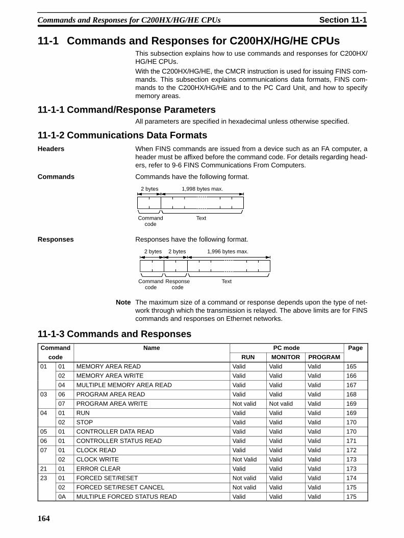
164
11-1 Commands and Responses for C200HX/HG/HE CPUsThis subsection explains how to use commands and responses for C200HX/HG/HE CPUs.With the C200HX/HG/HE, the CMCR instruction is used for issuing FINS com-mands. This subsection explains communications data formats, FINS com-mands to the C200HX/HG/HE and to the PC Card Unit, and how to specifymemory areas.
11-1-1 Command/Response ParametersAll parameters are specified in hexadecimal unless otherwise specified.
11-1-2 Communications Data FormatsHeaders When FINS commands are issued from a device such as an FA computer, a
header must be affixed before the command code. For details regarding head-ers, refer to 9-6 FINS Communications From Computers.
Commands Commands have the following format.
Commandcode
Text
2 bytes 1,998 bytes max.
Responses Responses have the following format.
Responsecode
TextCommandcode
2 bytes 1,996 bytes max.2 bytes
Note The maximum size of a command or response depends upon the type of net-work through which the transmission is relayed. The above limits are for FINScommands and responses on Ethernet networks.
11-1-3 Commands and ResponsesCommand Name PC mode Page
code RUN MONITOR PROGRAM
01 01 MEMORY AREA READ Valid Valid Valid 165
02 MEMORY AREA WRITE Valid Valid Valid 166
04 MULTIPLE MEMORY AREA READ Valid Valid Valid 167
03 06 PROGRAM AREA READ Valid Valid Valid 168
07 PROGRAM AREA WRITE Not valid Not valid Valid 169
04 01 RUN Valid Valid Valid 169
02 STOP Valid Valid Valid 170
05 01 CONTROLLER DATA READ Valid Valid Valid 170
06 01 CONTROLLER STATUS READ Valid Valid Valid 171
07 01 CLOCK READ Valid Valid Valid 172
02 CLOCK WRITE Not Valid Valid Valid 173
21 01 ERROR CLEAR Valid Valid Valid 173
23 01 FORCED SET/RESET Not valid Valid Valid 174
02 FORCED SET/RESET CANCEL Not valid Valid Valid 175
0A MULTIPLE FORCED STATUS READ Valid Valid Valid 175
Commands and Responses for C200HX/HG/HE CPUs Section 11-1

165
11-1-4 Memory Area DesignationsThe following table gives the addresses to use when reading or writing PC data.
Memory area Data Data area address Address used incommunications
Memoryarea code
No. ofbytes
1st and 2ndbytes
3rd byte
CIO area Bit status 00000 to 51115 0000 to 01FF 00 to 0F 00 1
Word contents 000 to 511 00 to 00 80 2
LR area Bit status LR 0000 to LR 6315 03E8 to 0427 00 to 0F 00 1
Word contents LR 00 to LR 63 00 to 00 80 2
HR area Bit status HR 0000 to HR 9915 0428 to 048B 00 to 0F 00 1
Word contents HR 00 to HR 99 00 to 00 80 2
AR area Bit status AR 0000 to AR 2715 048C to 04A7 00 to 0F 00 1
Word contents AR 00 to AR 27 00 to 00 80 2
Timer/CounterArea
CompletionFlag status
TIM 000 to TIM 511CNT 000 to CNT 511
0000 to 01FF 00 to 00 01 1
PV TIM 000 to TIM 511CNT 000 to CNT 511
00 to 00 81 2
DM Area Word contents DM 0000 to DM 9999 0000 to 270F 00 to 00 82 2
Expansion DMArea
Word contents EM 0000 to EM 6143 0000 to 17FF 00 to 00 90 to 98 2
Note 1. The size of the memory area varies depending on the PC. Refer to the PCsoperation manual for details on the size limits of the memory areas.
2. The meanings of the memory area codes for the Expansion DM area areshown below.
Memory area code Meaning
98 Current bank
90 to 97 Banks 0 to 7
A8 to AF Banks 8 to 15
11-1-5 MEMORY AREA READReads the contents of the specified number of consecutive memory area wordsstarting from the specified word. All words must be in the same memory area(here, all memory areas with the same memory area code are considered as onearea).
Note Even when the no. of items is 00, this command will end normally.
Command Block
Beginning word
Memory area code
No. of itemsCommandcode
Response Block
Responsecode
Commandcode
Data
Parameters Memory area code (command): The data area to read.
Commands and Responses for C200HX/HG/HE CPUs Section 11-1

166
Beginning word(command): The address of the first word/bit/flag to read frommemory. Specify 00 for the 3rd byte.
No. of items (command): The number of items to be read. Specify 0000 to03F1 (0 to 1009 decimal). The command can complete normally even if zeroitems are specified.
Data (response): The data from the specified words is returned in sequencestarting from the beginning address. PVs for timers and counters are returned asBCD. The required number of bytes in total is calculated as follows:
No. of bytes required by each item x No. of items
Memory AreasThe data in the following table can be read. (Refer to 11-1-4 Memory Area Desig-nations for PC word/bit address designations.)
Memory area Data Memory areacode
No. ofbytes
CIO, LR, HR, or ARarea
Word contents 80 2
Timer/Counter Completion Flag status 01 1
PV 81 2
DM Word contents 82 2
Expansion DM Word contents 90 to 98, A8 to AF
2
Response codeRefer to Appendix D Response Codes from the C200HX/HG/HE CPU andAppendix E FINS Response Codes from the PC Card Unit.
11-1-6 MEMORY AREA WRITEWrites data to the specified number of consecutive words starting from the spe-cified word.
Note a) Even when the no. of items is 00 this command will end normally.
b) When data is written in the Timer/Counter PV Area, the Comple-tion Flags will be turned OFF (0).
Command Block
Commandcode
Beginningword
No. of items Data
Memory area code
Response Block
Commandcode
Responsecode
Parameters Memory area code (command): The data area to write.
Beginning word(command): The first word/value to write. Specify 00 for the3rd byte.
No. of items (command): The number of items to be written. Specify 0000 to03E5 (0 to 997 decimal). The command can complete normally even if zeroitems are specified.
Commands and Responses for C200HX/HG/HE CPUs Section 11-1

167
Data (command): The data to be written. PVs for timers and counters are writ-ten as BCD. The required number of bytes in total is calculated as follows:
The required number of bytes in total is calculated as follows:
2 bytes x No. of items
The following data can be written (refer to 11-1-4 Memory Area Designations forthe word/bit address designations).
Memory area Data Memory areacode
No. ofbytes
CIO, LR, HR, or ARarea
Word contents 80 2
Timer/Counter PV 81 2
DM Word contents 82 2
Expansion DM Word contents 90 to 98, A8 to AF
2
Response codeRefer to Appendix D Response Codes from the C200HX/HG/HE CPU.
11-1-7 MULTIPLE MEMORY AREA READReads the contents of the specified number of non-consecutive memory areawords, starting from the specified word.
Note If there is an error in the command code or a beginning address, no data will beread.
Command Block
AddressCommandcode
Memory area code Memory area code
Address
128 addresses maximum
Response Block
Commandcode
Memory area code
Responsecode
Data
Memory area code
Data
Parameters Memory area code (command): The data area to read.
Address (command): The word/bit/flag to read. The content of up to 128addresses can be read. (If part of the data to be read is in the Expansion DMarea, the content of up to 100 addresses only can be read.)
Data (response): The data in the specified memory area(s) will be returned insequence starting from the beginning address.
Commands and Responses for C200HX/HG/HE CPUs Section 11-1

168
Memory AreasThe following data can be read (refer to 11-1-4 Memory Area Designations formemory area designations):
Memory area Data Memory areacode
No. ofbytes
CIO, LR, HR, or AR Bit status 00 1area Word contents 80 2
Timer/Counter Completion Flag status 01 1
PV 81 2
DM Word contents 82 2
Expansion DM Word contents 90 to 98, A8 to AF
2
Response codeRefer to Appendix D Response Codes from the C200HX/HG/HE CPU.
11-1-8 PROGRAM AREA READReads the contents of the specified number of consecutive program area wordsstarting from the specified word. The program is read in machine language(object code). A maximum of 512 bytes can be read with each command.
Command Block
Programno.
Beginning word No. ofbytes
Commandcode
Response Block
Beginning word DataProgramno.
No. ofbytes
Responsecode
Commandcode
512 bytes maximum
Parameters Program no. (command and response): Set to 0000.
Beginning word(command and response): Set a relative byte address with00000000 as the starting address. The beginning word must be an even num-ber. The address set in the command will be returned in the response.
No. of bytes (command and response): The number of bytes in an even num-ber 0200 (512 in decimal) or smaller. The number of bytes actually read will bereturned in the response. Bit 15 will be ON (1) in the response block when thelast word data of the program area is returned.
Bits 0 to 7 (second byte)
Bits 8 to 15 (first byte)
Bit 15 OFF (0): Without last word dataBit 15 ON (1): With last word dataBits 0 to 14: No. of bytes read
Data (response): The data in the specified program area will be returned insequence starting from the beginning word.
Note If the designated number of bytes is larger than the program area, the programwill be read through the final address and a response code indicating an addressrange error or response length error will be returned.
Commands and Responses for C200HX/HG/HE CPUs Section 11-1

169
Response codeRefer to Appendix D Response Codes from the C200HX/HG/HE CPU.
11-1-9 PROGRAM AREA WRITEWrites data to the specified number of consecutive program area words startingfrom the specified word. A maximum of 512 bytes can be written with each com-mand. To write larger amounts of data, use multiple commands and specify thebeginning word and number of words for each.
Note 1. When bit 15 is ON (1) the index create of the PC is activated.
2. When the no. of bytes is set to 8000, only an index marker is created.
Command Block
Programno.
Beginning word
DataNo. ofbytes
Commandcode
512 bytes maximum
Response Block
Beginning wordProgramno.
No. ofbytes
Responsecode
Commandcode
Parameters Program no. (command and response): Set to 0000.
Beginning word (command and response): Set a relative byte address with00000000 as the starting address. The beginning word must be an even num-ber. The address set in the command will be returned in the response.
No. of bytes (command and response): The number of bytes in an even num-ber (512 or smaller). The number of bytes actually written will be returned in theresponse. Bit 15 must be turned ON (1) when data for the last write to the pro-gram area so that the PC can generate an index. To write only an index marker,specify 8000 for the number of bytes.
Bits 0 to 7 (second byte)
Bits 8 to 15 (first byte)
Bit 15 OFF (0): Without last word dataBit 15 ON (1): With last word dataBits 0 to 14: No. of bytes written
Data (command): The data to be written.
Response codeRefer to Appendix D Response Codes from the C200HX/HG/HE CPU.
11-1-10 RUNChanges the PC to MONITOR or RUN mode, enabling the PC to execute its pro-gram.
Command Block
Programno.
ModeCommandcode
Commands and Responses for C200HX/HG/HE CPUs Section 11-1

170
Response Block
Responsecode
Commandcode
Parameters Program no. (command): Set to 0000.
Mode (command): As follows:
02: MONITOR mode
04: RUN mode
Response codeRefer to Appendix D Response Codes from the C200HX/HG/HE CPU.
Note If the mode is not specified, the PC will go to MONITOR mode.
11-1-11 STOPChanges the PC to PROGRAM mode, stopping program execution.
Command Block
Commandcode
Response Block
Responsecode
Commandcode
Response codeRefer to Appendix D Response Codes from the C200HX/HG/HE CPU.
11-1-12 CONTROLLER DATA READReads the following data:
• Controller model and version
• Area data
• PC status
Command Block
Commandcode
Response Block
Controllermodel
Controllerversion
Dummy 1 Area dataResponsecode
Commandcode
20 bytes 20 bytes 16 bytes 10 bytes
Peripheral Bus Connection
Dummy 2
65 bytes
Parameters Controller model and Controller version (response): Both are returned inASCII (20 bytes (i.e., 20 ASCII characters) max. each). If the model or version
Commands and Responses for C200HX/HG/HE CPUs Section 11-1

171
information does not require 20 bytes, the remainder of the 20 bytes will be filledwith spaces (ASCII 20).
Dummy 1 and Dummy 2 (response): All zeros will be returned.
Area data (response): As follows:
Programarea size
No. of DM words
Expansion DMsize
1st byte 10th byte
Item Meaning Unit
Program area size The size of PC Setup and program area K words (1K words = 1,024 words;1 word = 2 bytes))
No. of DM words Total words in the DM area6656 has no Expansion DM8000 Expansion DM has 1000 words9000 Expansion DM has 2000 words10000 Expansion DM has 3000 words
Words (1 word = 2 bytes)
Expansion DM size Banks in the Expansion DM area Banks (1 bank = 32,766 words)
Peripheral Bus Connection (response): The Peripheral Bus connection is indicated as follows:
00: No peripheral connection recognized80: Peripheral connected
Response codeRefer to Appendix D Response Codes from the C200HX/HG/HE CPU.
11-1-13 CONTROLLER STATUS READReads the status of the Controller.
Command Block
Commandcode
Response Block
Mode
Fatal errordata
Non-fatalerror data
FAL/FALS no.
Errormessage
Status
Responsecode
Commandcode
16 bytes
Parameters Status (response): The operating status of the PC as follows:00: STOP (program not being executed)01: RUN (program being executed)80: CPU on standby (the start switch is OFF or the CPU is waiting for a signalfrom a device such as a Remote I/O Slave Unit).
Mode (response): One of the following PC modes:00: PROGRAM02: MONITOR04: RUN
Commands and Responses for C200HX/HG/HE CPUs Section 11-1

172
Fatal error data (response): The contents of fatal error information from the PC(for details refer to your PC’s operation manual).
Bit
1: FALS error
1: No END instruction
1: I/O setting error
1: I/O unit overflow
1: I/O bus error
1: Memory error
Second byteFirst byte
Non-fatal error data (response): The contents of non-fatal error informationfrom the PC (for details refer to your PC’s operation manual).
Bit
1: PC Link error
1: Host Link error
1: Battery error
1: Remote I/O Unit error
1: CPU Bus Unit error
1: I/O verification error
1: Cycle time over
1: FAL error
Second byteFirst byte
FAL/FALS no. (response): The number of the highest priority FAL/FALS erroris returned as BCD between 00 and 99 (decimal) to the second byte. The firstbyte is always 00. If no error has occurred, 0000 is returned.
Error message (response): The error message of the present FAL/FALS num-ber is returned as 16 ASCII characters (16 bytes). If there is no error message,nothing will be returned.
Response codeRefer to Appendix D Response Codes from the C200HX/HG/HE CPU.
11-1-14 CLOCK READReads the clock.
Command Block
Commandcode
Response Block
YearMonth
DateHour
MinuteSecond
DayResponsecode
Commandcode
Parameters Year, month, date, hour, minute, second, day (response): Each value isexpressed in BCD.
Commands and Responses for C200HX/HG/HE CPUs Section 11-1

173
Year: The rightmost two digits of the year.Hour: 00 to 23.Day: As follows:
Value 00 01 02 03 04 05 06
Day Sun Mon Tues Wed Thur Fri Sat
Response codeRefer to Appendix D Response Codes from the C200HX/HG/HE CPU.
11-1-15 CLOCK WRITESets the clock.
Note Specify all data.
Command Block
YearMonth
DateHour
MinuteSecond
DayCommand
code
Response Block
Responsecode
Commandcode
Parameters Year, month, date, hour, minute, second, day (command): Each specifiedvalue is expressed in BCD.Year: The rightmost two digits of the year.Hour: Specify 00 to 23.Day: As follows:
Value 00 01 02 03 04 05 06
Day Sun Mon Tues Wed Thur Fri Sat
Response codeRefer to Appendix D Response Codes from the C200HX/HG/HE CPU.
11-1-16 ERROR CLEARClears errors from the PC. A normal response will be returned even if an errorhas not occurred.
Note The cause of the error must be removed before executing the ERROR CLEARcommand, or the same error will occur again after the ERROR CLEAR com-mand is executed.
Command Block
Commandcode
Error resetcode
Response Block
Commandcode
Responsecode
Parameters Error reset code (command): Set to FFFF.
Commands and Responses for C200HX/HG/HE CPUs Section 11-1

174
Response codeRefer to Appendix D Response Codes from the C200HX/HG/HE CPU.
11-1-17 FORCED SET/RESETForce-sets (ON) or force-resets (OFF) bits/flags or releases force-set status.Bits/flags that are forced ON or OFF will remain ON or OFF and cannot be writ-ten to until the forced status is released.
Note 1. This command cannot be used to release the status of Completion Flags fortimers or counters. If forced status is released and the Completion Flag isturned ON, it will be force-set; if forced status is released and the Comple-tion Flag is turned OFF, it will be force-reset.
2. FORCED SET/RESET can be used for more than one bit.
3. Forced status will be maintained until it is released using FORCED SET/RE-SET CANCEL.
Command Block
Commandcode
No. ofbits/flags
Bit/flagSet/Resetspecification
FORCED SET/RESET data
Memory area code
Set/resetspecification
Memory area code
Bit/flag
FORCED SET/RESET data
Response Block
Commandcode
Responsecode
Parameters No. of bits/flags (command): The number of bits/flags to be processed.
Set/Reset specification (command): The action to be taken for each bit/flag:
Value Name
0000 Force-reset (OFF) (0)
0001 Force-set (ON) (1)
8000 Forced status released and bit turned OFF (0)
8001 Forced status released and bit turned ON (1)
FFFF Forced status released
Memory area code (command): The memory area of the bit or flag to be con-trolled. Only the specified areas will be controlled. When using the PC Card Unitonly bits on the same word and memory area can be specified.
Bit/Flag (command): The bit or flag to be controlled.
Memory AreasThe bits (flags) in the following memory areas can be FORCED SET/RESET orreleased. (Refer to 11-1-4 Memory Area Designations for memory area desig-nations.)
Memory area Data Memory areacode
CIO, LR, HR, and ARareas
Bits status 00
Timer/Counter Completion Flag status 01
Commands and Responses for C200HX/HG/HE CPUs Section 11-1

175
Response codeRefer to Appendix D Response Codes from the C200HX/HG/HE CPU.
11-1-18 FORCED SET/RESET CANCELCancels all bits (flags) that have been forced ON or forced OFF.
Command Block
Commandcode
Response Block
Commandcode
Responsecode
Note The bits (flags) in the following memory areas can be forced set or forced reset.
Memory area Data
CIO, LR, HR, and ARareas
Bits status
Timer/Counter Completion Flag status
Response codeRefer to Appendix D Response Codes from the C200HX/HG/HE CPU.
11-1-19 MULTIPLE FORCED STATUS READReads the forced status of the specified range of words or timers/counters.
Command Block
Commandcode
Beginningword
Memoryarea code
Number ofunits
Response Block
Commandcode
Responsecode
Beginningword
Memoryarea code
DataNumber ofunits
Parameters Memory area code, Beginning word, Number of units (command,response): Specify the memory area code, the beginning word in that area, andthe number of words or timers/counters to read. The number of units can bebetween 0001 and 0040 (1 to 64 in decimal).
The actual area, beginning word, and number of unit to be read will be returnedin the response.
Commands and Responses for C200HX/HG/HE CPUs Section 11-1

176
Memory AreasForced status can be read in the following areas. Refer to 11-1-4 Memory AreaDesignations for memory area designations.
Area Data type Memory areacode
Number ofbytes
CIO, LR, HR, andAR areas
Current value of word 80 2
Timer/counter area Completion Flag status 01 1
Note Forced status is read by words for the CIO, LR, HR, or AR area and by bits (flags)for the timer/counter area.
Data (response): Forced status is returned beginning from the specified wordor timer/counter. The number of bytes returned will be (the number of units) x(the number of bytes/unit).
CIO, LR, HR, and AR Areas:
Bit 0
15 14 13 12 11 10 9 8 7 6 5 4 3 2 1 0Bit
Bit 1
Bit 2Bit 4Bit 6Bit 8Bit 10Bit 12Bit 14
Bit 3Bit 5Bit 9 Bit 7Bit 11Bit 13Bit 15
The status for each bit is as follows:OFF (0): No forced status in effectON (1): Forced ON or forced OFF
Timers/Counters: Status of the Completion Flag will be returned as fol-lows:
00: No forced status in effect01: Forced ON or forced OFF
Response codeRefer to Appendix D Response Codes from the C200HX/HG/HE CPU.
11-2 PC Card Unit Commands and ResponsesWhen a PC Card Unit receives a FINS command, it processes a response andreturns it to the node that sent the command.
11-2-1 PC Card Unit FINS Commands ListThe following is a list of the FINS commands supported by the PC Card Unit.
Command Code Name Page
05 01 CONTROLLER DATA READ 177
08 01 INTERNODE ECHO TEST 177
02 BROADCAST TEST RESULTS READ 178
03 BROADCAST TEST DATA SEND 178
21 02 ERROR LOG READ 179
03 ERROR LOG CLEAR 180
22 02 SINGLE FILE READ 180
03 SINGLE FILE WRITE 181
05 FILE DELETE 182
07 FILE COPY 182
08 FILE NAME CHANGE 183
12 SINGLE FILE READ WITH COMMAS 183
13 SINGLE FILE WRITE WITH COMMAS 184
PC Card Unit Commands and Responses Section 11-2

177
Note For details regarding FINS commands requesting socket services (27),refer to 11-3 FINS Commands Requesting Socket Services.
11-2-2 CONTROLLER DATA READReads the PC Card Unit’s model and version.
Command Block
0105
Commandcode
Response Block
Model VersionResponsecode
Commandcode
20 bytes 20 bytes 4 bytes 4 bytes
IP address Subnetmask
UDPport no.
Parameters Model (response): The model is returned in 20 bytes of ASCII (i.e., 20 ASCIIcharacters). If the model information does not require 20 bytes, the remainder ofthe 20 bytes will be filled with spaces ($20).
Version (response): The version is returned in 20 bytes of ASCII (i.e., 20 ASCIIcharacters). If the version information does not require 20 bytes, the remainderof the 20 bytes will be filled with spaces ($20).
IP address, subnet mask (response):There are four bytes returned respectively for the PC Card Unit’s IP address andsubnet mask.
UDP port number for FINS (response):There are two bytes returned for the PC Card Unit’s FINS UDP port.
Response codeRefer to Appendix E FINS Response Codes from the PC Card Unit.
11-2-3 INTERNODE ECHO TESTPerforms an internode echo test with specified nodes.
Command Block2 bytes 1,996 bytes max.
Commandcode
Test data
Response Block2 bytes 1,996 bytes max.
Commandcode
Test data
2 bytes
Responsecode
Parameters Test data (command, response): Up to 1,996 bytes of test data can beincluded in the command. This data is transmitted to the indicated node andreturned unchanged if communications are normal. If the data returned in theresponse differs from that transmitted in the command, it means that an erroroccurred in the test.
PC Card Unit Commands and Responses Section 11-2
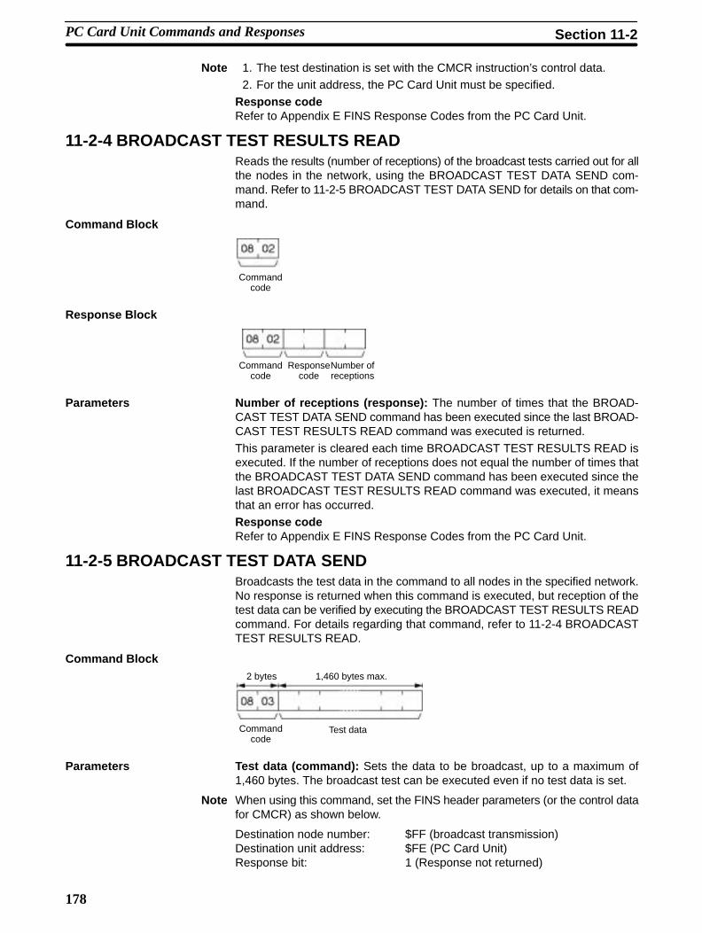
178
Note 1. The test destination is set with the CMCR instruction’s control data.2. For the unit address, the PC Card Unit must be specified.
Response codeRefer to Appendix E FINS Response Codes from the PC Card Unit.
11-2-4 BROADCAST TEST RESULTS READReads the results (number of receptions) of the broadcast tests carried out for allthe nodes in the network, using the BROADCAST TEST DATA SEND com-mand. Refer to 11-2-5 BROADCAST TEST DATA SEND for details on that com-mand.
Command Block
Commandcode
Response Block
Commandcode
Number ofreceptions
Responsecode
Parameters Number of receptions (response): The number of times that the BROAD-CAST TEST DATA SEND command has been executed since the last BROAD-CAST TEST RESULTS READ command was executed is returned.
This parameter is cleared each time BROADCAST TEST RESULTS READ isexecuted. If the number of receptions does not equal the number of times thatthe BROADCAST TEST DATA SEND command has been executed since thelast BROADCAST TEST RESULTS READ command was executed, it meansthat an error has occurred.Response codeRefer to Appendix E FINS Response Codes from the PC Card Unit.
11-2-5 BROADCAST TEST DATA SENDBroadcasts the test data in the command to all nodes in the specified network.No response is returned when this command is executed, but reception of thetest data can be verified by executing the BROADCAST TEST RESULTS READcommand. For details regarding that command, refer to 11-2-4 BROADCASTTEST RESULTS READ.
Command Block2 bytes 1,460 bytes max.
Commandcode
Test data
Parameters Test data (command): Sets the data to be broadcast, up to a maximum of1,460 bytes. The broadcast test can be executed even if no test data is set.
Note When using this command, set the FINS header parameters (or the control datafor CMCR) as shown below.
Destination node number: $FF (broadcast transmission)Destination unit address: $FE (PC Card Unit)Response bit: 1 (Response not returned)
PC Card Unit Commands and Responses Section 11-2

179
Response codeRefer to Appendix E FINS Response Codes from the PC Card Unit.
11-2-6 ERROR LOG READReads the error data from the PC Card Unit. Error data is erased after it has beenread.
Command Block
Commandcode
Beginningrecord no.
No. ofrecords
Parameters Beginning record no. (command): Designates the beginning record numberin a range of 0000 to 0006 (0 to 6 in decimal). The first record is 0000. When errordata is read from the middle, all preceding data is erased from the system. Onerecord consists of 10 bytes and stores the data for one error record.
No. of records (command): Designates the number of records to be read in arange of 0001 to 0007 (1 to 7 in decimal).
Response Block
Error logdata
Responsecode
Commandcode
Max. no.of storedrecords
No. of storedrecords
No. ofrecords
10 bytes Xn
Parameters Max. no. of stored records (response): Designates the maximum number ofrecords stored. For the PC Card Unit, this is always 7.
No. of stored records (response): Returns the number of records remainingafter records have been read. When no records have been read, returns the cur-rent number of records.
No. of records read (response): Returns the actual number of records read.
Error log data (response): Error log data is stored record by record in the fol-lowing block.
Year (the rightmost two digits)
BCD
Error type
Error code
MinutesSeconds
DayHour
Month
Refer to 12-1-2 Error Log and Indicators for details on error codes.
Response codeRefer to Appendix E FINS Response Codes from the PC Card Unit.
PC Card Unit Commands and Responses Section 11-2

180
11-2-7 ERROR LOG CLEARResets the PC Card Unit’s Error Log.
Command Block
Commandformat
Response Block
Commandformat
Responsecode
Response codeRefer to Appendix E FINS Response Codes from the PC Card Unit.
11-2-8 SINGLE FILE READReads the contents of a file stored in the file device connected to the PC CardUnit.
Command Block
File offsetDisk no.Commandcode
File name Data length
12 bytes
Parameters Disk no. (command): Specify the file device from which to read as follows:G drive (slot 1): $0006 H drive (slot 2): $0007
File name (command): The name of the file to be read (in capital letters). Set as: File name of up to eight letters + period + 3-letter extension. One-bytealphanumeric is used. When there are not enough letters in the name to fill 12bytes, fill the remaining bytes with spaces ($20).
File offset (command): Designates the offset from the beginning of the file fromwhich to start reading.
Data length (command): Designates the number of bytes to be read. When setto 0000, checks whether there is any data in the file at the specified offset.
Response Block
File capacityResponsecode
Commandcode
Data lengthFile offset Data
Parameters File capacity (response): File size in bytes. When a SINGLE FILE READ isexecuted for a file with a capacity of 0 bytes (no data), the data length will be0000 and no data will be returned.
File offset (response): Returns the offset from the beginning of the file.
Data length (response): Returns the actual number of bytes of data read.
Data: Data is returned in sequence from the beginning word (offset) through thespecified data length.
Response codeRefer to Appendix E FINS Response Codes from the PC Card Unit.
PC Card Unit Commands and Responses Section 11-2

181
11-2-9 SINGLE FILE WRITEWrites a new file to the file device connected to the PC Card Unit or appends/overwrites an existing file stored in the file device. Designation can be made toprotect existing files if an attempt is made to create a new file of the same nameas an existing file.
Note Do not create any files on the memory card that begin with “TMP...”. The systemuses this prefix.
Command Block
Disk no.Commandcode
Data lengthFile offsetFile nameParameter File data
12 bytes ? byte
Parameters Disk no. (command): Specify the file device to which to write (in the PC CardUnit) as follows:G drive (slot 1): $0006 H drive (slot 2): $0007
Parameter (command): As follows:0000: Writes a new file. If a file with the same name already exists, the newfile will not be created.0001: Writes a new file. If a file with the same name already exists, it will beoverwritten.0002: Appends data to an existing file. (Appended to the end of the file.)0003: Overwrites an existing file.
File name (command): The name of the file to be written (in capital letters).Set as: File name of up to eight letters + period + 3-letter extension. One-bytealphanumeric code is used. When there are not enough letters to fill all 12 bytes,fill the remaining bytes with spaces ($20).
File offset (command): The number of bytes from the start of the file from whichto start writing (files start at 00000000). To create a new file or append data to anexisting file, specify 00000000 as the file offset.
Data length (command): The number of bytes to be written.
File data (command): The data to be written to the file. The data is written insequence from the file offset through the specified data length.
Response Block
Responsecode
Commandcode
Note 1. If the data length is set to 0000 when creating a new file, a file with capacity of0 (no data) will be created.
2. If the data length is set to 0000 when overwriting an existing file, the com-mand will check whether there is any data at the file offset.
3. When the data exceeds the file device’s remaining capacity SINGLE FILEWRITE cannot be executed. In this case the contents of the existing file willbe left unchanged.
4. When a SINGLE FILE WRITE is executed, the PC Card Unit’s time data willbe used to record the time and date of the file.
Response codeRefer to Appendix E FINS Response Codes from the PC Card Unit.
PC Card Unit Commands and Responses Section 11-2

182
11-2-10 FILE DELETEDeletes files stored in a file device connected to the PC Card Unit.
Command Block
22 05
Disk no.Commandcode
No. offiles
File name File name
12 bytes 12 bytes
Parameters Disk no. (command): Specify the file device (memory card) as follows:G drive (slot 1): $0006 H drive (slot 2): $0007
No. of files (command): The number of files to be deleted
File name (command): The names of the files to be deleted (in capital letters).Set as: File name of up to eight letters + period + 3-letter extension. One-bytealphanumeric code is used. When there are not enough letters to fill all 12 bytes,fill the remaining bytes with spaces ($20).
Response Block
Responsecode
Commandcode
No. offiles
No. of files (response): The number of files that have been deleted.
Note 1. The specified files will be deleted in sequence. If nonexisting file nameshave been specified, the PC Card Unit will ignore them and the operation willcontinue.
2. If the specified number of files and the number of file names do not coincideno files will be deleted.
Response codeRefer to Appendix E FINS Response Codes from the PC Card Unit.
11-2-11 FILE COPYCopies a file onto the memory card of the PC Card Unit.
Note Do not create any files on the memory card that begin with “TMP...”. The systemuses this prefix.
Command Block
Commandcode
Disk no. (Destination)
12 bytes 12 bytes
File name (Destination)
File name (Source)
Disk no. (Source)
Parameters Disk no. (command): Set the file device (memory cards) as follows:G drive: $0006 H drive: $0007
File name (command): The file to be copied and a new name for the copied file. Set as: File name of up to eight letters + period + 3-letter extension. One-byteShift JIS alphanumeric code is used. When there are not enough letters to fill all12 bytes, fill the remaining bytes with spaces ($20).
PC Card Unit Commands and Responses Section 11-2

183
Response Block
Responsecode
Commandcode
Note 1. The copied file name cannot be omitted, even if the destination and sourcefile names are the same.
2. The file will not be copied if an existing file name is given.
3. When a FILE COPY is executed, the PC Card Unit’s time data will be used torecord the time and date of the copied file.
Response codeRefer to Appendix E FINS Response Codes from the PC Card Unit.
11-2-12 FILE NAME CHANGEChanges a file name.
Note Do not create any files on the memory card that begin with “TMP...”. The systemuses this prefix.
Command Block
Commandcode
Disk no. Old file name
New file name
12 bytes 12 bytes
Disk no. (command): Set the file device (memory cards) as follows:G drive (slot 1): $0006 H drive (slot 2): $0007
Parameters Old file name (command): The original file name for the file.
New file name (command): The new name for the file. The file will not be copiedif an existing file name is given. Set as: File name of up to eight letters + period +3-letter extension. One-byte alphanumeric code is used. When there are notenough letters to fill all 12 bytes, fill the remaining bytes with spaces ($20).
Response Block
Commandcode
Responsecode
Response codeRefer to Appendix E FINS Response Codes from the PC Card Unit.
11-2-13 SINGLE FILE READ WITH COMMASReads file data contained in the file device connected to the PC Card Unit.Reads specified files as comma-separated value files (CSV files), and thenremoves the commas before returning the data.
Command Block
File offsetDisk no.Commandcode
File name Data length
12 bytes
Parameters Disk no. (command): Set the file device (on the PC Card Unit) as follows:G drive (slot 1): $0006 H drive (slot 2): $0007
PC Card Unit Commands and Responses Section 11-2

184
Beginning file name (command): The name of the file to be read.Set as: File name of up to eight letters + period + 3-letter extension. One-bytealphanumeric code is used. When there are not enough letters to fill all 12 bytes,fill the remaining bytes with spaces ($20).File offset (command): Designates the offset from the beginning of the file fromwhich to start reading.Data length (command): The number of bytes to be read. The file is comma-separated and the data will thus be in word units. Therefore, set the number ofbytes to an even number. When the length is set to 0000, the command willcheck whether there is any data at the file offset.
Response Block
File capacityResponsecode
Commandcode
Data lengthFile offset Data
Parameters File capacity (response): The capacity (bytes) of the file that was read. Whenthe file capacity is 0 bytes and the SINGLE FILE READ is executed, the datalength will be 0000 and no data will be read.File offset (response): File offset from the first byte of the file is returned.Data length (response): The number of bytes read.Data: The data is read in sequence from the file offset through the specified datalength.Response codeRefer to Appendix E FINS Response Codes from the PC Card Unit.
11-2-14 SINGLE FILE WRITE WITH COMMASWrites a new file to the file device connected to the PC Card Unit or appendsto/overwrites an existing file stored in the file device. Writes specified files ascomma-separated value files (CSV files), i.e., adds commas to the data beforewriting the files. Designation can be made to protect existing files if an attempt ismade to create a new file of the same name as an existing file.
Note Do not create any files on the Memory Card that begin with “TMP...”. The systemuses this prefix.
Command Block
Disk no.Commandcode
Data lengthFile offsetFile nameParameter File data
12 bytes ? byte
Parameters Disk no. (command): File offset codes for data on a PC Card Unit are desig-nated as follows:G drive (slot 1): $0006 H drive (slot 2): $0007Parameter (command): As follows:
0000: Writes a new file. If a file with the same name already exists, the newfile will not be created.0001: Writes a new file. If a file with the same name already exists, it will beoverwritten.0002: Appends data to an existing file. (Appended to the end of the file.)0003: Overwrites an existing file.
File name (command): The name of the file to be written.Set as: File name of up to eight letters + period + 3-letter extension. One-bytealphanumeric code is used. When there are not enough letters to fill all 12 bytes,fill the remaining bytes with spaces ($20).
PC Card Unit Commands and Responses Section 11-2

185
File offset (command): The number of bytes from the start of the file from whichto start writing (files start at 00000000). To create a new file or add data to anexisting file, specify 00000000 as the file offset.
Data length (command): The number of bytes to be written.
File data (command) : The data to be written to the file. The data is written insequence from the file offset through the specified data length.
Responsecode
Commandcode
Response codeRefer to Appendix E FINS Response Codes from the PC Card Unit.
Note 1. If the data length is set to 0000 when creating a new file, a file with capacity of0 (no data) will be created.
2. If the data length is set to 0000 when overwriting an existing file, the com-mand will check whether there is any data at the file offset.
3. When the data exceeds the file device’s remaining capacity SINGLE FILEWRITE cannot be executed. In this case the contents of the existing file willbe left unchanged.
4. When a SINGLE FILE WRITE is executed, the PC Card Unit’s time data willbe used to record the time and date of the file.
5. The PC Card Unit’s time will revert to that of the PC to which it is connectedwhen either the power supply is turned on or it is reset.
11-3 FINS Commands Requesting Socket ServicesThis subsection explains the FINS commands that request socket services forthe PC Card Unit. These FINS commands are used for executing communica-tions by TCP/IP or UDP/IP.
11-3-1 Summary of Commands
The following table summarizes the FINS commands requesting socket ser-vices for PC Card Unit response processing.
Command code Name Page
MRC SRC27 01 UDP OPEN REQUEST 187
02 UDP RECEIVE REQUEST 188
03 UDP SEND REQUEST 189
04 UDP CLOSE REQUEST 190
10 TCP OPEN REQUEST (PASSIVE) 191
11 TCP OPEN REQUEST (ACTIVE) 192
12 TCP RECEIVE REQUEST 193
13 TCP SEND REQUEST 194
14 TCP CLOSE REQUEST 195
FINS Commands Requesting Socket Services Section 11-3

186
11-3-2 Socket Status AreaEach PC Card Unit has four sockets that can be used for TCP or UDP. The statusof each of these sockets can be confirmed from the respective AR bits.
AR Words 08 to 15
Byte
Operating level #0, socket no. 1 status area
Operating level #0, socket no. 2 status area
Operating level #0, socket no. 3 status area
Operating level #0, socket no. 4 status area
Operating level #1, socket no. 1 status area
Operating level #1, socket no. 2 status area
Operating level #1, socket no. 3 status area
Operating level #1, socket no. 4 status area
Bit Configuration The meaning of individual bits in each status word is shown in the following dia-gram.
Bit
Open Flag
Results Storage Error Flag
Socket Classification Flag Closing Flag
Sending Flag
Receiving Flag
Opening Flag
Bit Flag Value Status Description
Bit 0 Opening Flag 1 Opening ON when an open request is received.
0 Open complete OFF when opening has been completed.
Bit 1 Receiving Flag 1 Receiving ON when a receive request is received.
0 Receive complete OFF when receive has been completed.
Bit 2 Sending Flag 1 Sending ON when a send request is received.
0 Send complete OFF when send has been completed.
Bit 3 Closing Flag 1 Closing ON when a close request is received.
0 Close complete OFF when close has been completed.
Bit 4 to 12 Not used
Bit 13 SocketClassification
1 TCP socket Indicates that the open socket is a TCP socket.(This has no meaning if the Open Flag is “0.”)
Flag 0 UDP socket Indicates that the open socket is a UDP socket.(This has no meaning if the Open Flag is “0.”)
Bit 14 Results StorageError Flag
1 Results storageerror
ON when the results storage area is incorrectlydefined for a FINS command sent to a PC CardUnit. This flag will not turn ON until the Opening,Receiving, Sending, and Closing Flags turn OFF.
0 Results storagenormal
OFF when the next service is requested at thesocket.
Bit 15 Open Flag 1 Open (connected) ON when opening has been completed. This flagindicates the TCP socket is connected.
0 Closed OFF when closing has been completed. RemainsOFF if an error occurs during opening.
FINS Commands Requesting Socket Services Section 11-3

187
11-3-3 UDP OPEN REQUESTRequests processing to open a socket.
Command Block
Commandcode
0127
UDPsocketnumber
Results storage area Local UDPport number
Response Block
0127
Commandcode
Responsecode
Results Storage Format
Results storageresponse code
Parameters UDP Socket Number (Command): Specify the UDP socket number to beopened as two bytes between 1 and 4.
Results Storage Area (Command): The words 0 to 255 and 256 to 511 of thememory area, words 0 to 6143 of the data memory, and words 0 to 6143 (eachbank) of the expansion data memory can be used. However, do not designatethe special auxiliary area. Refer to 11-1-4 Memory Area Designations. When abank that does not have expansion data memory is designated, the ResultsStorage Area Error Flag will turn ON.
Local UDP Port Number (Command): The UDP port number for communica-tions with the socket is specified as two bytes (0 cannot be specified). Packetsreceived at this port are distributed to the socket specified in the UDP socketnumber, and send packets are distributed from the UDP socket to this port. Theport number specified as the FINS UDP port number (default value 9600) cannotbe used.
Note Do not designate the port that is being used as the UDP port number for FINS(default: 9600).
Response code Description
0000 Normal
1100 UDP socket number is out of range.
Local UDP port number is zero.
1101 The memory area code for the results storage area is out ofrange.
1103 Non-zero bit address is specified for the results storage area.
220F Specified socket is already open.
Response code Description
0000 Normal
003E Cannot secure the internal buffer. (ENOBUFS)
0049 Duplicate UDP port number. (EADDRINUSE)
Response Codes
Results Storage AreaResponse Codes
FINS Commands Requesting Socket Services Section 11-3

188
11-3-4 UDP RECEIVE REQUESTRequests that data be received from a UDP socket.
Command Block
0227
Commandcode
UDPsocketnumber
Results storage area Number ofreceptionbytes
Timeoutvalue
Response Block
0227
Commandcode
Responsecode
Results Storage Format
0227
Resultsstorageresponsecode
Source IPaddress
SourceUDP portnumber
Number ofreceptionbytes
Received data
Parameters UDP Socket Number (Command): Specify the UDP socket number to beopened as two bytes between 1 and 4.
Results Storage Area (Command): The words 0 to 255 and 256 to 511 of thememory area, words 0 to 6143 of the data memory, and words 0 to 6143 (eachbank) of the expansion data memory can be used. However, do not designatethe special auxiliary area. Refer to 11-1-4 Memory Area Designations. When abank that does not have expansion data memory is designated, the ResultsStorage Area Error Flag will turn ON.
Number of Reception Bytes (Command, Results Storage Area): The maxi-mum number of bytes of data to be received is given in the command. The num-ber of bytes of data received will be stored in the results storage area. Up to1,982 bytes can be specified.
Note If more than the specified number of bytes is received, only the specified amountwill be stored and the remainder will be discarded.
Timeout Value (Command): Specifies the maximum control time betweenreceiving the receive request and storing the result. If this set time limit isexceeded, the code for a timeout error (0080) will be set as the results storageresponse code. The value is set in units of 0.1 s. The timeout time will be unlim-ited if the value is set to 0.
Source IP Address (Results Storage Area): The IP address of the node send-ing data.
Source UDP Port Number (Results Storage Area): The port number of thenode sending data.
Received Data (Results Storage Area): The data sent from the remote node.
FINS Commands Requesting Socket Services Section 11-3

189
Response code Description
0000 Normal
1100 UDP socket number or number of reception bytes is out ofrange.
1101 The memory area code for the results storage area is out ofrange.
1103 Non-zero bit address is specified for the results storage area.
2201 The specified socket is opened as a TCP socket.
220F The specified socket is currently receiving data.
2210 The specified socket is not open.
Response code Description
0000 Normal
0042 Message size was too large to be stored in the buffer.(EMSGSIZE)
0080 A timeout error occurred.
0081 The specified socket was closed while receiving data.
11-3-5 UDP SEND REQUESTRequests that data be sent by a UDP socket.
Command Block
0327
Commandcode
UDPsocketnumber
Results storage area Destination IPaddress
DestinationUDP portnumber
Number ofbytes sent
1982 bytes max.
Send data
Response Block
0327
Commandcode
Responsecode
Results Storage Format
Responsecode
Number ofbytes sent
Parameters UDP Socket Number (Command): Specify the UDP socket number to beopened as two bytes between 1 and 4.Results Storage Area (Command): The words 0 to 255 and 256 to 511 of thememory area, words 0 to 6143 of the data memory, and words 0 to 6143 (eachbank) of the expansion data memory can be used. However, do not designatethe special auxiliary area. Refer to 11-1-4 Memory Area Designations. When abank that does not have expansion data memory is designated, the ResultsStorage Area Error Flag will turn ON.Destination IP Address (Command): Specifies in hexadecimal the IP addressof the node to which data is being sent. For broadcasting, set everything to “1” forthe host address.Destination UDP Port Number (Command): Specifies in hexadecimal theUDP port number of the node to which data is being sent.Number of Bytes Sent (Command, Results Storage Area): The number ofbytes in the data sent by this command. Up to 1,982 bytes can be specified, or upto 1,472 bytes can be specified if the broadcast address is specified as the senddestination. The results storage area stores the actual number of bytes sent.
Response Codes
Results Storage AreaResponse Codes
FINS Commands Requesting Socket Services Section 11-3

190
Send Data (Command): Specifies the data sent to the remote node.
Response code Description
0000 Normal
1003 The number of bytes sent does not match the sent datalength.
1100 UDP socket number or number of bytes sent is out of range.The destination IP address is 0.
1101 The memory area code for the results storage area is out ofrange.
1103 Non-zero bit address is specified for the results storage area.
2201 The specified socket is opened as a TCP socket.
220F The specified socket is currently receiving data.
2210 The specified socket is not open.
Response code Description
0000 Normal
0042 The send destination IP address is a broadcast address andthe number of bytes sent exceeds 1,472. (EMSGSIZE)
004E Could not reach the remote network. (ENETUNREACH)
11-3-6 UDP CLOSE REQUESTRequests processing to close a socket.
Command Block
0427
Commandcode
UDPsocketnumber
Results storage area
Response Block
0427
Commandcode
Responsecode
Results Storage Format
Responsecode
Parameters UDP Socket Number (Command): Specify the UDP socket number to beopened as two bytes between 1 and 4.
Results Storage Area (Command): The words 0 to 255 and 256 to 511 of thememory area, words 0 to 6143 of the data memory, and words 0 to 6143 (eachbank) of the expansion data memory can be used. However, do not designatethe special auxiliary area. Refer to 11-1-4 Memory Area Designations. When abank that does not have expansion data memory is designated, the ResultsStorage Area Error Flag will turn ON.
Response Codes
Results Storage AreaResponse Codes
FINS Commands Requesting Socket Services Section 11-3

191
Response code Description
0000 Normal
1100 UDP socket number is out of range.
1101 The memory area code for the results storage area is out ofrange.
1103 Non-zero bit address is specified for the results storage area.
2201 The specified socket is opened as a TCP socket.
2210 Specified socket is not open.
Response code Description
0000 Normal
11-3-7 TCP OPEN REQUEST (PASSIVE)Requests processing to open a TCP socket. The socket will wait to be connectedto another node.
Command Block
1027
Commandcode
TCPsocketnumber
Results storage area LocalTCPportnumber
Timeoutvalue
Remote IPaddress
Remote TCPport number
Response Block
1027
Commandcode
Responsecode
Results Storage Format
Responsecode
Remote IPaddress
Remote portnumber
Parameters TCP Socket Number (Command): Specify the TCP socket number to beopened as two bytes between 1 and 4.
Results Storage Area (Command): The words 0 to 255 and 256 to 511 of thememory area, words 0 to 6143 of the data memory, and words 0 to 6143 (eachbank) of the expansion data memory can be used. However, do not designatethe special auxiliary area. Refer to 11-1-4 Memory Area Designations. When abank that does not have expansion data memory is designated, the ResultsStorage Area Error Flag will turn ON.
Local TCP Port Number (Command): The TCP port number for communica-tions with the socket is specified as two bytes.
Timeout Value (Command): The maximum control time between receiving theopen request and storing the result. If this set time limit is exceeded, the code fora timeout error (0080) will be set as the results storage response code. Thevalue is set in units of 0.1 s. The timeout time is unlimited if the value is set to 0.
Remote IP Address (Command, Results Storage Area): Specify the remotenode’s IP address. If all zeroes are set, no remote node is specified and connec-tion is awaited from any node. If any other value is set, connection is awaitedfrom the specified remote node. The IP address of the connected remote nodewill be stored in the results storage area.
Response Codes
Results Storage AreaResponse Codes
FINS Commands Requesting Socket Services Section 11-3

192
Remote Port Number (Command, Results Storage Area): Specify theremote TCP port number with this command. If all zeroes are set, no remoteTCP port number is specified. If any other value is set, it specifies the TCP portnumber of the remote node. The TCP port number of the connected remotenode will be stored in the results storage area.
Response code Description
0000 Normal
1100 TCP socket number is out of range.
Remote IP address is 0.
1101 The memory area code for the results storage area is out ofrange.
1103 Non-zero bit address is specified for the results storage area.
220F The specified socket (connection) is already open or iscurrently being opened.
Response code Description
0000 Normal
003E Cannot secure the internal buffer. (ENOBUFS)
0080 An open request timeout error occurred.
11-3-8 TCP OPEN REQUEST (ACTIVE)Requests processing to open a TCP socket. The socket will be connected toanother node.
Command Block
1127
Commandcode
Results storagearea
TCPsocketnumber
LocalTCP portnumber
Remote IPaddress
RemoteTCP portnumber
Response Block
1127
Commandcode
Responsecode
Results Storage Format
Responsecode
Local portnumber
Parameters TCP Socket Number (Command): Specify the TCP socket number to beopened as two bytes between 1 and 4.Results Storage Area (Command): The words 0 to 255 and 256 to 511 of thememory area, words 0 to 6143 of the data memory, and words 0 to 6143 (eachbank) of the expansion data memory can be used. However, do not designatethe special auxiliary area. Refer to 11-1-4 Memory Area Designations. When abank that does not have expansion data memory is designated, the ResultsStorage Area Error Flag will turn ON.Local TCP Port Number (Command, Results Storage Area): The local TCPport number is specified as two bytes. An available TCP port number is automat-ically assigned if 0 is specified. The TCP port number allocated to the opensocket is stored in the results storage area.
Note Do not make other port specifications if you specify the local TCP port number.Making other specifications may cause transmissions to collide on the port.
Response Codes
Results Storage AreaResponse Codes
FINS Commands Requesting Socket Services Section 11-3

193
Remote IP Address (Command): Specify the remote node’s IP address (mustbe non-zero).
Remote Port Number (Command): Specify the remote TCP port number(must be non-zero).
Response code Description
0000 Normal
1100 TCP socket number is out of range or remote IP address is0.
1101 The memory area code for the results storage area is out ofrange.
1103 Non-zero bit address is specified for the results storage area.
220F The specified socket is already open or is being opened.
Response code Description
0000 Normal
003E Cannot secure the internal buffer. (ENOBUFS)
0049 Duplicated TCP port numbers. (EADDRINUSE)
004A A communication error occurred with the remote node.(ENCONNREFUSED) Passive remote is not available. Anattempt was made to actively open local TCP port.
004C The designated IP address is not correct. (EADRNOTAVAIL)
0053 A communication error occurred with the remote node. Noremote exists. (ETIMEDOUT)
11-3-9 TCP RECEIVE REQUESTRequests that data be received from a TCP socket.
Command Block
1227
Commandcode
Results storagearea
TCPsocketnumber
Number ofreceptionbytes
Timeoutvalue
Response Block
1227
Commandcode
Responsecode
Results Storage Format
Received bytes
Responsecode
Number ofreceptionbytes
Received data
Parameters TCP Socket Number (Command): Specify the TCP socket number to beopened as two bytes between 1 and 4.
Results Storage Area (Command): The words 0 to 255 and 256 to 511 of thememory area, words 0 to 6143 of the data memory, and words 0 to 6143 (eachbank) of the expansion data memory can be used. However, do not designatethe special auxiliary area. Refer to 11-1-4 Memory Area Designations. When abank that does not have expansion data memory is designated, the ResultsStorage Area Error Flag will turn ON.
Response Codes
Results Storage AreaResponse Codes
FINS Commands Requesting Socket Services Section 11-3

194
Number of Reception Bytes (Command, Results Storage Area): The maxi-mum number of bytes of data to be received is given in the command. The num-ber of bytes of data received will be stored in the results storage area. Up to1,982 bytes can be specified.
Reception of 0 bytes indicates that the communications were forcibly cut by theremote node. Close the socket.
Note If more than the specified number of bytes is received, only the specified amountwill be stored and the remainder will be read when the next data set is received.
Timeout Value (Command): The maximum control time between receiving thereceive request and storing the result. If this set time limit is exceeded, the codefor a timeout error (0080) will be set as the results storage response code. Thevalue is set in units of 0.1 s. The timeout time is unlimited if the value is set to 0.
Received Data (Results Storage Area): Stores the received data.
Response code Description
0000 Normal
1100 TCP socket number is out of range.Number of reception bytes is out of range (i.e., over 1982).
1101 The memory area code for the results storage area is out ofrange.
1103 Non-zero bit address is specified for the results storage area.
2201 The specified socket is opened as a UDP socket.
220F The specified socket is receiving data.
2210 The specified socket is not open.
Response code Description
0000 Normal
0016 Connection has not been established due to cable trouble,etc., and the receive request became an error. (EINVAL)
0040 Received by a socket not connected. (ENOTCONN)
0042 Message size was too large to be stored in the buffer.(EMSGSIZE)
004B An error occurred in communications with the remote node.(ECONNRESET)
0080 A timeout error occurred.
0081 Socket was closed while receiving.
11-3-10 TCP SEND REQUESTRequests that data be sent by a TCP socket.
Command Block
1327 1,982 bytes max.
Commandcode
TCPsocketnumber
Results storagearea
Number ofbytes sent
Data sent
Response Block
1327
Commandcode
Responsecode
Response Codes
Results Storage AreaResponse Codes
FINS Commands Requesting Socket Services Section 11-3

195
Results Storage Format
Responsecode
Number ofbytes sent
Parameters TCP Socket Number (Command): Specify the TCP socket number to beopened as two bytes between 1 and 4.Results Storage Area (Command): The words 0 to 255 and 256 to 511 of thememory area, words 0 to 6143 of the data memory, and words 0 to 6143 (eachbank) of the expansion data memory can be used. However, do not designatethe special auxiliary area. Refer to 11-1-4 Memory Area Designations. When abank that does not have expansion data memory is designated, the ResultsStorage Area Error Flag will turn ON.Number of Bytes Sent (Command, Results Storage Area): The number ofbytes in the data sent is specified between 1 and 1,982. The results storage areastores the actual number of bytes sent.Data Sent (Command): Specifies the data to be sent.
Response code Description
0000 Normal
1003 The number of bytes sent does not match the amount ofdata.
1100 The TCP socket number or number of bytes sent is out ofrange.
1101 The memory area code for the results storage area is out ofrange.
1103 Non-zero bit address is specified for the results storage area.
2201 The specified socket is opened as a UDP socket.
220F The specified socket is sending data.
2210 The specified socket is not open.
Response code Description
0000 Normal
0016 Connection has not been established due to cable trouble,etc., and the send request became an error. (EINVAL)
0020 Socket connection broken during transmission.
003E Cannot secure the internal buffer. (ENOBUFS)
0045 An error occurred in communications with the remote node.(ECONNABORTED)
004B An error occurred in communications with the remote node.(ECONNRESET)
004E Could not reach the remote network. (ENETUNREACH)
0053 An error occurred in communications with the remote node.(ETIMEDOUT)
0081 The specified socket was closed during transmission.
11-3-11 TCP CLOSE REQUESTRequests processing to close a TCP socket. Other processing being carried outis forcibly ended and a code is recorded in the results storage area.
Command Block
1427
Commandcode
Results storagearea
TCPsocketnumber
Response Codes
Results Storage AreaResponse Codes
FINS Commands Requesting Socket Services Section 11-3

196
Response Block
1427
Commandcode
Responsecode
Results Storage Format
Responsecode
Parameters TCP Socket Number (Command): Specify the TCP socket number to beopened as two bytes between 1 and 4.
Results Storage Area (Command): The words 0 to 255 and 256 to 511 of thememory area, words 0 to 6143 of the data memory, and words 0 to 6143 (eachbank) of the expansion data memory can be used. However, do not designatethe special auxiliary area. Refer to 11-1-4 Memory Area Designations. When abank that does not have expansion data memory is designated, the ResultsStorage Area Error Flag will turn ON.
Note Any other processing, such as sending or receiving data, being carried out whenthis close command is executed will be forcibly ended and a code will be storedin the results storage area to indicate that this processing was forcibly ended.Wait for the close processing on the connected node side.
Response code Description
0000 Normal
1100 The TCP socket number is out of range.
1101 The memory area code for the results storage area is out ofrange.
1103 Non-zero bit address is specified for the results storage area.
2201 The specified socket is opened as a UDP socket.
2210 No connection could be established to the specified socket.
Response code Description
0000 Normal
Response Codes
Results Storage AreaResponse Codes
FINS Commands Requesting Socket Services Section 11-3

197
Part 4Troubleshooting
This part of the manual includes information on troubleshooting errors andusing the error log.

199
SECTION 12Error Processing
This section describes the meaning of indicators and the actions to be taken when the indicators light. It also explains how touse the error log.
12-1 Indicators and the Error Log 200. . . . . . . . . . . . . . . . . . . . . . . . . . . . . . . . . . . . . . . . . . . . . . . . 12-1-1 Reading the Error Log 200. . . . . . . . . . . . . . . . . . . . . . . . . . . . . . . . . . . . . . . . . . . . . . 12-1-2 Error Log 200. . . . . . . . . . . . . . . . . . . . . . . . . . . . . . . . . . . . . . . . . . . . . . . . . . . . . . . . 12-1-3 Troubleshooting Using Indicators 200. . . . . . . . . . . . . . . . . . . . . . . . . . . . . . . . . . . . .
12-2 Troubleshooting 201. . . . . . . . . . . . . . . . . . . . . . . . . . . . . . . . . . . . . . . . . . . . . . . . . . . . . . . . . . 12-3 Echo Test With PING Command 201. . . . . . . . . . . . . . . . . . . . . . . . . . . . . . . . . . . . . . . . . . . . .
12-3-1 PING Command 201. . . . . . . . . . . . . . . . . . . . . . . . . . . . . . . . . . . . . . . . . . . . . . . . . . 12-3-2 Using the Host Computer 201. . . . . . . . . . . . . . . . . . . . . . . . . . . . . . . . . . . . . . . . . . . 12-3-3 Using PING from a Unix Computer 202. . . . . . . . . . . . . . . . . . . . . . . . . . . . . . . . . . .

200
12-1 Indicators and the Error LogWhen an error occurs in the CPU bus, Ethernet network, or other parts of thesystem, the PC Card Unit indicates the error with indicators and records it in theerror log to enable the user to identify the error. This section explains how toretrieve the records in the error log and describes the error log and indicators.
Note Turning the PC Card Unit OFF erases the error log. To prevent this, alwaysretrieve the error log before turning the PC Card Unit OFF.
12-1-1 Reading the Error LogTo read the error log, execute the FINS command ERROR LOG READ (com-mand code 21 02) from another computer or CV-series CPU, addressing it to thePC Card Unit.Refer to ERROR LOG READ in 11-2 PC Card Unit Commands and Responsesfor details on command usage and response details.
12-1-2 Error LogThe following table describes the error types and codes recorded by the PCCard Unit.
Error type Code Description Action2 1 The PC is not the C200HX/HG/HE. ---
3 CPU watchdog timer error Eliminate the cause of the problem in the main PCCPU.
3 1 Ethernet initialization failure. Socketopen error. (See note.)
Check the settings and correct where necessary.
2 Other Ethernet errors. IP cannot beused. (See note.)
Same as above.
Note Type-3 errors don’t occur with the C200HW-PCU01.
12-1-3 Troubleshooting Using IndicatorsERR indicator RUN indicator Cause and action
Lit Lit A message was received from a node that is notregistered on the conversion table for IPaddresses and FINS node addresses. (Does notoccur with C200HW-PCS01-V2.)
In this case, the received message is processed,but the response is discarded. Unit operationcontinues. Register the node if necessary.
ERR indicator RUN indicator Cause and actionLit --- A watchdog timer error occurred at the main PC
CPU.Eliminate the cause of the problem at the PC.
A Unit memory parity error (hardware error)occurred. Replace the Unit if necessary.
Lit Not lit The default ODI driver is set at the time ofdelivery. (Occurs with C200HW-PCS01-V2 only.)Change the setting to that of the ODI driver forthe Ethernet card used.
There is an error in the settings (e.g. the ODIdriver setting). (Occurs with C200HW-PCS01-V2only.) Check the settings and correct wherenecessary.
The access right for data servicing between thePC Card Unit and the PC has not been releasedfrom the PC.Check the connections between devices, andreset the power supply.
Non-fatal Errors
Fatal Errors
Indicators and the Error Log Section 12-1

201
12-2 TroubleshootingFormatting Does Not Finish:
If card access indicator is flashing:Formatting is in progress. Wait until formatting is complete.If card access indicator is not flashing:Check whether the card type and the slot match the switch settings. Also, con-tact the card manufacturer to check whether the card can be used with PHOE-NIX PCM Plus 3.2.Try formatting once with a personal computer.
Check the parameters.Check whether the card is write-protected.Check whether the file name extension is three characters.Check whether the correct drive and directory are specified.Check whether a directory has been created beforehand.
Check whether the command parameters are correctly specified.Check whether the cable is correctly connected.Issue a PING command from the personal computer. If PING response is notreturned, repeat the setup procedure.
If the power is interrupted during a file transfer, the built-in flash file system will bedamaged and it may not be possible to start up in file transfer mode. If thatoccurs, it will be necessary to have the Unit repaired.
12-3 Echo Test With PING CommandThe PC Card Unit incorporates the PING command supported as a standardfeature by many host computers. The PING command is an echo test usingICMP (Internet Control Message Protocol).
12-3-1 PING CommandThe PING command sends an echo request packet to a remote node andreceives an echo response packet to confirm that the remote node is communi-cating correctly. The PING command uses the ICMP echo request andresponses. The echo response packet is automatically returned by the ICMP.
The PING command is normally used to check the connections of remote nodeswhen configuring a network. The PC Card Unit supports both the ICMP echorequest and reply functions.
CPU
TCP UDP
ICMP IP
ETHERNET
Echo request
Response
Remote node (host com-puter or PC Card Unit)
PC
Car
d U
nit
12-3-2 Using the Host ComputerThe PING command can be executed from the host computer to send an echorequest packet to a PC Card Unit. The method for using the PING commandfrom a Unix computer is described below.
CMCR Terminates With anError:
SEND or RECV Times Out:
RUN Indicator Does NotLight in File Transfer Mode,and then the Unit Does NotRun in Any Mode:
Echo Test With PING Command Section 12-3

202
12-3-3 Using PING from a Unix ComputerInput the following at the host computer prompt ($):$ ping IP_address (host_name)
The destination is specified by its IP address or host name. If the host name isused, the host name must be defined in file /etc/hosts.
Note The PING command is not supported by some host computers.
Application ExamplesThese examples show sending the PING command to the node at IP address130.25.36.8. The “$” on the example screen represents the host computerprompt. User inputs are underlined. Comments are placed after semicolons.
Normal Execution $ ping 130.25.36.8 ; Executes PING commandPING 130.25.36.8: 56 data bytes
64 bytes from 130.25.36.8: icmp_seq=0. time=0.ms
64 bytes from 130.25.36.8: icmp_seq=0. time=0.ms
. . .
. . .
. . .
64 bytes from 130.25.36.8: icmp_seq=0. time=0.ms
←Enter DEL key to cancel. ;User presses DEL key.––––130.25.36.8 PING Statistics––––
9 packets transmitted, 9 packets received, 0% packets loss
round-trip (ms) min/avg/max = 0/1/16
$
Abnormal Execution $ ping 130.25.36.8 ; Executes PING commandPING 130.25.36.8: 56 data bytes
←Enter DEL key to cancel. ;User presses DEL key.––––130.25.36.8 PING Statistics––––
9 packets transmitted, 0 packets received, 100% packets loss
$
Refer to operating system documentation for your host computer for detailsabout using the host computer’s PING command.
Echo Test With PING Command Section 12-3

203
Appendix AStandard Models
Name Specifications Model
PC Card Unit Does not support Ethernet. C200HW-PCU01
PC Card Unit Ethernet Set Supports Ethernet C200HW-PCS01-EV1
Bus Connection Unit Connects one PC Card Unit C200HW-CE011
Connects one PC Card Unit and oneSYSMAC LINK or SYSMAC NET LinkUnit.
C200HW-CE012
Communications Board CPU bus interface only C200HW-COM01
CPU bus interface and RS-232C port C200HW-COM04-E
Ethernet Setup Software Provided with C200HW-PCS01. –––

205
Appendix BSpecifications
PC Card Unit SpecificationsThe specifications for the PC Card Unit are shown below.
General SpecificationsGeneral specifications are the same as those for the SYSMAC Series.
Item Specifications
CPU 80386SX 25 MHz
Memory 1 MB DRAM
ROM 512 KB (BIOS, DOS, System file storage)
FLASH ROM 1 MB (System file storage)
RTC No battery backup
Serial port RS-232C × 1 channel (terminal connection setup)
PC card interface PCMCIA 2.1 (3.3-V low-voltage specification not supported)Type II × 2 slots or Type III × 1 slot
PC interface SYSMAC CPU bus interface
LED indicators RUN, ERR, PC card access, PC card formatting
Setting switch DIP switch × 6
Power supply +5 VDC
Currentconsumption
+5 VDC, 0.7 A max. (for each Unit) + PC card output current(Icard)
I5V (1 slot) 0.5 A, I12V (1 slot) 0.1 A
However, Icard = I5V (2 slots) + 3.4 × I12V (2 slots) 1.0 A
Dimensions 34.5 × 130 × 125 (WxHxD)
Weight 400 g max.

Appendix BSpecifications
206
Dimensions(Unit: mm)
Backplane
Backplane
Plate 3
When using an Ethernet card, be sure toallow sufficient room to install the cable.

207
Appendix CConnector Pin Assignments
Connector Pin AssignmentsThe assignments of the connector pins for the PC Card Unit are shown below.
PC Card Interface(*denotes negative logic)
Pin number Signal names Pin number Signal names
1 GND 35 GND
2 D3 36 CD1*
3 D4 37 D11
4 D5 38 D12
5 D6 39 D13
6 D7 40 D14
7 CE1* 41 D15
8 A10 42 CE2*
9 E* 43 RFSH
10 A11 44 IORD*
11 A9 45 IOWR*
12 A8 46 A17
13 A13 47 A18
14 A14 48 A19
15 WE*/PGM 49 A20
16 RDY/BSY* /REQ*[I/O Card]
50 A21
17 VCC 51 VCC
18 VPP1 52 VPP2
19 A16 53 A22
20 A15 54 A23
21 A12 55 A24
22 A7 56 A25
23 A6 57 Reserved (N.C.)
24 A5 58 RESET
25 A4 59 WAIT*
26 A3 60 NPACK* [I/O Card]
27 A2 61 REG*
28 A1 62 BVD2/SPKR* [I/O Card]
29 A0 63 BVD1/STSCHG* [I/OCard]
30 D0 64 D8
31 D1 65 D9
32 D2 66 D10
33 WP/IOCS16* [I/O Card] 67 CD2*
34 GND 68 GND

Appendix CConnector Pin Assignments
208
PC Card slot 2
A 2-slot, 68-pin connector for a PC card (with ejector)
PC Card slot 1
PC Card slot 2-1PC Card slot 2-35
PC Card slot 1-1PC Card slot 1-35
PC Card slot 2-34PC Card slot 2-68
PC Card slot 1-34PC Card slot 1-68
Serial Communications InterfacePin number Signal names Pin number Signal names
1 FG 6 NC
2 SD 7 DR
3 RD 8 ER
4 RS 9 SG
5 CS Connectorbase
FG
PC Card Unit side
(D sub 9-pin female connector)
Cable Wiring
Wire the cable similarly to the following connections.
The following Connector and Connector Cover are available if you want to pro-duce your own cable. Wire the cable with care.
Connector XM2A-0901 OMRON
Connector Cover XM2S-0911 OMRON
Connection
D sub 9-pinPC Card Unit Personal Computer IBM PC/AT or
compatibleFG hood
Shield
D sub 25-pin D sub 9-pin
FG hood FG hood
–3278654
General Serial ConnectorSignals
Applicable Connector

209
Appendix DResponse Codes from the C200HX/HG/HE CPU
The following table lists the response codes (main and sub-codes) returned after execution of FINS commands,the probable cause of the errors, and recommended remedies.
Upon receipt of some commands, the destination node will issue a request to another node; the other node isreferred to as the third node.
Response codes for FINS commands consist of two bytes that indicate the result of executing a command. Thestructure of the response codes is shown in the following diagram.
7 6 5 4 3 2 1 0 7 6 5 4 3 2 1 0Bit
1: PC Non-fatal Error Flag
1: PC Fatal Error Flag
1: Relay Error Flag
First byte Second byte
Main response code (MRES) Sub-response code (SRES)
The main response code (MRES) in the first byte classifies the response and the sub-response code (SRES) in thesecond byte indicates details under the MRES classification. If bit 7 of the first byte is ON (1), a network relay errorhas occurred. Refer to Network Relay Errors in the FINS Commands Reference Manual for details on trouble-shooting the error. If bit 6 or 7 of the second byte is ON, an error has occurred in the PC or computer returning theresponse. Refer to the operation manual for the device returning the response for details when troubleshooting theerror.
Main code Sub-code
Probable cause Remedy
00: Normal completion 00 --- ---
01: Local node error 01 Service was interrupted Check the contents of the destinationtransmission area of third node.Check the data link status.
01 Local node not part of network Add to network.
02 Token time-out, node number toolarge
Set the local node’s node number belowthe maximum node number.
03 Number of transmit retries exceeded Check communications with internodeecho test. If the test fails, check network.
04 Maximum number of frames exceeded Either check the execution of events in thenetwork and reduce the number of eventsoccurring in one cycle, or increase themaximum number of frames.
05 Node number setting error (range) Make sure the node number is withinspecified range and that there are noduplicate node numbers.
06 Node number duplication error Make sure that there are no duplicate nodenumbers.

Appendix DResponse Codes from the C200HX/HG/HE CPU
210
Main code RemedyProbable causeSub-code
02: Destination node 01 Destination node not part of network Add to network.error 02 No node with the specified node
numberCheck the destination node’s nodenumber.
03 Third node not part of network Check the third node’s node number.
Broadcasting was specified. Check the control data and specify onlyone node as the third node.
04 Busy error, destination node busy Increase the number of transmit retryattempts or re-evaluate the system so thatthe destination node is not so busyreceiving data.
05 Response time-out, message packetwas corrupted by noise
Increase the number of transmit retryattempts.
Response time-out, response watch-dog timer interval too short
Increase the value for the response watch-dog timer interval in the control data.
Frame lost in transmission Check the error log and correct theprocess.
03: Communicationscontroller error
01 Error occurred in the communicationscontroller, ERC indicator is lit
Take corrective action, referring tocommunications controller errors andremedies table at the end of this section
02 CPU error occurred in the PC at thedestination node
Clear the error in the CPU (refer to thePC’s operation manuals)
03 A controller error has prevented anormal response from being returned.
Check network communications status andreset the controller board. If the error stillexists, replace the controller board.
04 Node number setting error Make sure the node number is withinspecified range and that there are noduplicate node numbers.
04: Not executable 01 An undefined command has beenused.
Check the command code and be surethat the Unit supports it.
02 Cannot process command becausethe specified unit model or version iswrong.
Check the unit model and version.
05: Routing error 01 Destination node number is not set inthe routing table.
Set the destination node number in therouting table.
02 Routing table isn’t registered. Set the source nodes, destination nodes,and relay nodes in the routing table.
03 Routing table error Set the routing table correctly.
04 The maximum number of relay nodes(2) was exceeded in the command.
Redesign the network or reconsider therouting table to reduce the number of relaynodes in the command.
10: Command formaterror
01 The command is longer than the max.permissible length.
Check the command format of thecommand and set it correctly.
02 The command is shorter than min.permissible length.
Check the command format of thecommand and set it correctly.
03 The designated number of data itemsdiffers from the actual number.
Check the number of items and the data,and make sure that they agree.
04 An incorrect command format hasbeen used.
Check the command format of thecommand and set it correctly.
05 An incorrect header has been used.(The local node’s relay table or relaynode’s local network table is wrong.)
Set the routing table correctly.

Appendix DResponse Codes from the C200HX/HG/HE CPU
211
Main code RemedyProbable causeSub-code
11: Parameter error 01 A correct memory area code has notbeen used or Expansion Data Memoryis not available.
Check the command’s memory area codeand set the appropriate code.
02 The access size specified in thecommand is wrong, or the firstaddress is an odd number.
Set the correct access size for thecommand.
03 The first address is in an inaccessiblearea.
Set a first address that is in an accessiblearea.
04 The end of specified word rangeexceeds the acceptable range.
Check the acceptable limits of the dataarea and set the word range within thelimits.
Check the data link tables to be sure thelimit to link words has not been exceeded.
06 A non-existent program no. has beenspecified.
Check the program number and be surethat it is set correctly.
09 The sizes of data items in thecommand block are wrong.
Check the command data and be sure thatthe sixes of the data items are correct.
Check the data link tables to be sure allnodes in the refresh parameters are in thecommon link parameters.
0A The IOM break function cannot beexecuted because it is already beingexecuted.
Either abort the current IOM break functionprocessing, or wait until it is completed andexecute the command.
Check the data link tables for duplicatenode numbers.
0B The response block is longer than themax. permissible length.
Check the command format and set thenumber of items correctly.
0C An incorrect parameter code has beenspecified.
Check the command data and reenter itcorrectly.Check the data link table file for corruption.
20: Read not possible 02 The data is protected. Execute the instruction again after issuingthe PROGRAM AREA PROTECT CLEARcommand.
An attempt was made to download afile that is being uploaded.
Check the file name and either interruptservicing or wait for servicing to completebefore re-executing the command.
03 The registered table does not exist oris incorrect.
Set or reset the registered table.
Too many files open. Close open files and re-execute thecommand.
04 The corresponding search data doesnot exist.
---
05 A non-existing program no. has beenspecified.
Check the program number and be surethat it is set correctly.
06 A non-existing file has been specified. Check whether the correct file name wasused.
07 A verification error has occurred. Check whether the memory contents arecorrect and replace if incorrect.
Check the contents of the file. A read errormay have occurred.

Appendix DResponse Codes from the C200HX/HG/HE CPU
212
Main code RemedyProbable causeSub-code
21: Write not possible 01 The specified area is read-only or iswrite-protected.
If the specified area is read-only, the writecannot be performed. If it iswrite-protected, turn off the write-protectswitch and execute the instruction again.
02 The data is protected. Execute the instruction again after issuingthe PROGRAM AREA PROTECT CLEARcommand.
An attempt was made tosimultaneously download and uploada file.
Check the file name and either interruptservicing or wait for servicing to completebefore re-executing the command.
The data link table cannot be writtenmanually because it is set forautomatic generation.
Change the system settings to manualdata link table generation.
03 The number of files exceeds themaximum permissible.
Write the file(s) again after erasingunneeded files, or use different disk ormemory card that has free space.
Too many files open. Close open files and re-execute thecommand.
05 A non-existing program no. has beenspecified.
Check the program number and be surethat it is set correctly.
06 A non-existent file has been specified. ---
07 The specified file already exists. Change the name of the file and executethe instruction again.
08 Data cannot be changed. Check the contents of the memory areabeing written to.
22: Not executable in 01 The mode is wrong (executing). Check the operating mode.current mode Data links are active. Check the data link status before
execution.02 The mode is wrong (stopped). Check the operating mode.
Data links are active. Check the data link status beforeexecution.
03 The PC is in the PROGRAM mode. Check the PC’s mode.
04 The PC is in the DEBUG mode. Check the PC’s mode.
05 The PC is in the MONITOR mode. Check the PC’s mode.
06 The PC is in the RUN mode. Check the PC’s mode.
07 The specified node is not the controlnode.
Check which node is the control node.
08 The mode is wrong and the stepcannot be executed.
Check whether the step has active statusor not.
23: No Unit 01 A file device does not exist wherespecified.
Mount the memory card or disk
02 The specified memory does not exist. Check the specifications of the installed filememory.
03 No clock exists. Check the model number.
05 Ethernet setting error. The IP addressof the destination node has not beenset.
Run SETUP and add the address.
24: Start/stop notpossible
01 The data link table either hasn’t beencreated or is incorrect.
Set the data link table correctly.

Appendix DResponse Codes from the C200HX/HG/HE CPU
213
Main code RemedyProbable causeSub-code
25: Unit error 02 Parity/checksum error occurredbecause of incorrect data.
Transfer correct data into memory.
03 I/O setting error (The registered I/Oconfiguration differs from the actual.)
Either change the actual configuration tomatch the registered one, or generate theI/O table again.
04 Too many I/O points Redesign the system to remain withinpermissible limits.
05 CPU bus error (An error occurredduring data transfer between the CPUand a CPU Bus Unit.)
Check the Unit, Service Boards, and cableconnections and issue the ERROR CLEARcommand.
06 I/O duplication error (A rack number,unit number, or I/O word allocationhas been duplicated.)
Check the system’s settings and eliminateany duplication.
07 I/O bus error (An error occurred duringdata transfer between the CPU and anI/O Unit.)
Check the Unit, Service Boards, and cableconnections and issue the ERROR CLEARcommand.
09 SYSMAC BUS/2 error (An erroroccurred during SYSMAC BUS/2 datatransfer.)
Check the Unit, Service Boards, and cableconnections and issue the ERROR CLEARcommand.
0A Special I/O Unit error (An erroroccurred during CPU Bus Unit datatransfer.)
Check the Unit, Service Boards, and cableconnections and issue the ERROR CLEARcommand.
0D Duplication in SYSMAC BUS wordallocation.
Check and regenerate the I/O table.
0F A memory error has occurred ininternal memory, in the memory card,or in Expansion DM during the errorcheck.
If the error occurred in internal memory orthe EM Unit, correct the data in thecommand an execute it again.
If the error occurred in a memory card orEM used for file memory, the file data hasbeen corrupted. Execute the MEMORYCARD FORMAT command.
If the above remedies do not eliminate theerror, replace the faulty memory.
10 Terminator not connected in SYSMACBUS System.
Connect the terminator correctly.

Appendix DResponse Codes from the C200HX/HG/HE CPU
214
Main code RemedyProbable causeSub-code
26: Command error 01 The specified area is not protected.This response code will be returned ifan attempt is made to clear protectionon an area that is not protected.
The program area is not protected, so itisn’t necessary to clear protection.
02 An incorrect password has beenspecified.
Specify a password that is registered.
04 The specified area is protected. Execute the command again after thePROGRAM AREA PROTECT CLEARcommand.
Too many commands at destination. The destination has received more than 5commands. Either interrupt servicing orwait for servicing to complete beforere-executing the command.
05 The service is being executed. Execute the command again after theservice has been completed or aborted.
06 The service is not being executed. Execute the service if necessary.
07 Service cannot be executed from localnode because the local node is notpart of the data link.
Execute the service from a node that ispart of the data link.
A buffer error has prevented returninga normal response.
Reset the board. If the error persists,replace the board.
08 Service cannot be executed becausenecessary settings haven’t beenmade.
Make the necessary settings.
09 Service cannot be executed becausenecessary settings haven’t been madein the command data.
Check the command format and make thenecessary settings.
0A The specified action or transitionnumber has already been registered.
Execute the command again using anaction or transition number that hasn’tbeen registered.
0B Cannot clear error because the causeof the error still exists.
Eliminate the cause of the error andexecute the ERROR CLEAR command.
30: Access right error 01 The access right is held by anotherdevice.
Execute the command again after theaccess right has been released.
(The command can be executed after theACCESS RIGHT FORCED ACQUIRE orACCESS RIGHT RELEASE command iscompleted. Releasing the access rightmight affect processes in progress at thenode that held the access right.)
40: Abort 01 Command was aborted with ABORTcommand.
---

215
Appendix EFINS Response Codes from the PC Card Unit
When an error occurs in a FINS command sent to a PC Card Unit, an error response code is returned. Althoughthere are other response codes that are given only for certain commands, the following is a list of response codescommon to all commands.
Response code Cause
0103 Transmission buffer full; transmission not possible.
0201 Destination IP address not recognized; transmission notpossible.
0202 Specified Unit nonexistent; transmission not possible.
0301 Network error; transmission not possible.
0401 Command frame not supported (MRC, SRC).
0401 Unsupported FINS frame (Protocol) received.
0501 Routing table setting error; transmission not possible.
0502 Routing table nonexistent; transmission not possible.
0503 Routing table error; transmission not possible.
1005 FINS frame with an incorrect destination received.
1001 Transmission size exceeds 1472 bytes.
2305 IP address cannot be converted; transmission not possible.

217
Appendix FDifferences with the CV-series or CS1-series Ethernet Units
The differences between the PC Card Unit (C200HW-PCS01-V2) and the CV-series or CS1-series Ethernet Unitsare listed below.
Functions Not Supported by the PC Card Unit• There is no FTP Server function.
• CMND instructions cannot be used.
• 10BASE-5 is not supported.
Differences in Standard Protocol, Socket Service Functions• The PC Card Unit has a total of four TCP/IP and UDP/IP sockets, whereas the CV-series and CS1-series Ether-
net Units have eight UDP/IP sockets.
• The PC Card Unit uses the CMCR instruction for FINS communications, whereas the CV-series and CS1-seriesEthernet Units use the CMND instruction.
Differences in FINS Command/Response Communications• When commands are transmitted from the Programmable Controller to the host, the PC Card Unit uses the
CMCR instruction, whereas the CV-series and CS1-series Ethernet Units use the CMND instruction.
• When commands from the host are received at the Programmable Controller, the PC Card Unit cannot receivemultiple FINS commands simultaneously from multiple nodes. After receiving a command, it processes the com-mand and sends a response to the host. If it receives another command before that process has been com-pleted, it returns a “node busy” error message.
Differences in Ethernet Connectors• The PC Card Unit supports 10Base-T and 10Base-2 (using commercially available PC Cards).
• The CV-series and CS1-series Ethernet Units support 10Base-5.
Differences in Mail Support• The PC Card Unit and CV-series Ethernet Unit do not support sending mail.
• The CS1-series Ethernet Unit does support sending mail.

219
Appendix GExample Using a Memory Card with a Personal Computer
The procedure for reading a file saved on the PC Card Unit in comma-separated format, on the personal computerin EXCEL is described below.
C200HW-PCU01/PCS01-V2 PC Card Unit
Memory Card
Personal computer
The personal computer operating environment used in this example is as follows:
• MS-Windows 95
• EXCEL
• Built-in PC Card driver
1, 2, 3... 1. Insert the Memory Card created on the PC Card Unit into the PC Card slot on the personal com-puter.
2. In EXCEL select “Open” from the “File” menu.
3. Set the file type to “Text file.”
4. Select “Comma or space separated file.”The file will be read as a comma-separated file.
Note Only numerical values in decimals can be read.

221
Appendix HPrecautions when Setting Up the Network
• Be sure to follow the safety precautions and specifications when setting up the Ethernet network. Refer to ISO/IEC 8802-3 for laying the Ethernet.
• It is recommended that network construction be carried out by qualified personnel with an extensive knowledgeof safety precautions and specifications.
• Do not install Ethernet network equipment in the vicinity of noisy equipment. When installing in a noisy environ-ment, ensure that each individual network device is in a metal case and that the noise procedures for all opticalcables is followed.
• When executing transmission using the UDP/IP, whose communications protocol doesn’t perform re-transmis-sion processing (FINS communications), be sure to execute re-transmission using the user program.

223
Appendix IContents of Version Upgrade
This appendix outlines the functions that have been added with upgrades.
Upgrading from C200HW-PCS01 to C200HW-PCS01-EV1
Socket Interface SupportUDP and TCP socket interfaces are supported by FINS commands. Refer to Section 9 FINS Commands and Sec-tion 10 Socket Services.
Remote Tool ConnectionRemote tool connection to the C200HX/HG/HE via the PC Card Unit interface is made possible by peripheral busconnection to the C200HX/HG/HE and host link connection from SYSMAC Support Software (SSS).
With remote tool connection via PC Card Unit Ethernet, it is not possible to use SYSMAC Link-related functionssuch as starting and stopping SYSMAC Link and making data link settings.
Refer to Appendix J Remote Tool Connection Procedure.
FINS Command Expansion• 0501: Added data such as local IP address, FINS UDP port number, etc., to response.
• 0801: Added loopback command.
• Added commands for socket interface.
Refer to Section 11 Using FINS Commands and Responses.
Setup Software Expansion• Added function for reading Ethernet settings.
• Added function for clearing Ethernet settings.
Refer to 7-7 Using SETUP2.EXE.
FINS Address ChecksWhen a message is received from a node that is not registered on the conversion table for IP addresses and FINSnode addresses, the received message is processed but the response is discarded. Unit operation continues.
Upgrading from C200HW-PCS01-EV1 to C200HW-PCS01-V2
Installation of Setting FilesFiles required for Ethernet communications functions have been installed in the Unit.
Refer to 7-6 Setup Software Operation.
Note Do not use the setup software for the C200HW-PCS01(-EV1) to perform settings for the C200HW-PCS01-V2.

225
Appendix JRemote Tool Connection Procedure
This appendix explains the procedure for remote tool connection to the C200HX/HG/HE via the PC Card Unit inter-face by peripheral bus connection to the C200HX/HG/HE and host link connection from SYSMAC Support Soft-ware (SSS).
OutlineWhen the system is configured as shown in the following diagram, remote tool connection can be executed for aC200HX/HG/HE on the Ethernet.
System Configuration Example
Ethernet
C200HW-PCS01-V2PC Card Unit
C200HW-PCS01-V2PC Card Unit
C200HW-PCS01-V2PC Card Unit
Host link orperipheral busconnection
Personal computer,SYSMAC SupportSoftware (SSS)
• Remote tool connection can only be executed between C200HX/HG/HE Programmable Controllers with PCCard Units mounted. It cannot be executed for other C-series or CV-series PCs.
• Remote tool connection cannot be executed unless the Ethernet environmental settings are completed for thePC Card Units at both the local and remote nodes.
• Personal computers with SYSMAC Support Software installed can be connected to C200HX/HG/HE Program-mable Controllers by host link or by peripheral bus. If a personal computer is directly connected to a PC CardUnit, peripheral bus connection cannot be used.
RestrictionsWith remote tool connection via PCU Card Unit Ethernet, it is not possible to use SYSMAC Link-related functionssuch as starting and stopping SYSMAC Link and making data link settings.

Appendix JRemote Tool Connection Procedure
226
Settings for Peripheral BusUse the SYSMAC Support Software to make the settings as shown in the following procedure.
1, 2, 3... 1. Select “C:PC interface” from the System Setup Menu.2. Select “L:Peripheral Bus (via SYSMAC LINK).”
3. Select “K:Level” or “B:Baud rate.”
[ Level ]0: Level #01: Level #1
[ Baud rate ]A: 19,200B: 9,600C: 4,800
“Level” is the system of the PC Card Unit connected to the C200HX/HG/HE.
Settings for Host LinkUse the SYSMAC Support Software to make the settings as shown in the following procedure.
Note When communicating from a C200HX/HG/HE Communications Board, make sure that the SYSMAC LINKPeripheral Device Initialization Bit (AR 2403) is turned ON when the SYSMAC Support Software connec-tion port is changed.
1, 2, 3... 1. Select “C:PC interface” from the System Setup Menu.2. Select “C:Host Link (via SYSMAC LINK).”
3. Set the level, baud rate, number of data bits, the host link unit number, parity, and number of stopbits as required.
[ Level ]0: Level #01: Level #1
[ Baud rate ]A: 19,200B: 9,600C: 4,800D: 2,400
[ Data bit ]7: 7 bits8: 8 bits
[ Unit No. ]00 unit
(00 to 31)
[ Stop bits ]1: 1 bit2: 2 bits
[ Parity ]E: Even parityO: Odd parityN: No parity
Note This procedure cannot be used with the base-mounted C200H-LK201-(V1) Host Link Unit.

227
Glossary
address A number used to identify the location of data or programming instructions inmemory or to identify the location of a network or a unit in a network.
advertisement The process of sending out information to make resources available to otherdevices, e.g., sending information to other nodes in a network to make windowsavailable for communications.
allocation The process by which the PC assigns certain bits or words in memory for variousfunctions. This includes pairing I/O bits to I/O points on Units.
area See data area and memory area.
ARP Address Resolution Protocol: Determines the Ethernet address (i.e., physicaladdress) by broadcasting based on the target IP address.
ASCII Short for American Standard Code for Information Interchange. ASCII is used tocode characters for output to printers and other external devices.
asynchronous execution Execution of programs and servicing operations in which program executionand servicing are not synchronized with each other.
Auxiliary Area A PC data area allocated to flags and control bits.
back-up A copy made of existing data to ensure that the data will not be lost even if theoriginal data is corrupted or erased.
baud rate The data transmission speed between two devices in a system measured in bitsper second.
BCD Short for binary-coded decimal.
binary A number system where all numbers are expressed in base 2, i.e., numbers arewritten using only 0’s and 1’s. Each group of four binary bits is equivalent to onehexadecimal digit. Binary data in memory is thus often expressed in hexadeci-mal for convenience.
binary-coded decimal A system used to represent numbers so that every four binary bits is numericallyequivalent to one decimal digit.
bit The smallest piece of information that can be represented on a computer. A bithas the value of either zero or one, corresponding to the electrical signals ONand OFF. A bit represents one binary digit. Some bits at particular addresses areallocated to special purposes, such as holding the status of input from externaldevices, while other bits are available for general use in programming.
bit address The location in memory where a bit of data is stored. A bit address specifies thedata area and word that is being addressed as well as the number of the bitwithin the word.
broadcast The process of sending data simultaneously to all nodes on a single network andused to test network communications.
buffer A temporary storage space for data in a computerized device.

Glossary
228
Bus Connection Unit A Unit used to connect a single PC Card Unit to the C200HX/HG/HE PC or to oneSYSMAC LINK Unit or SYSMAC NET Link Unit to the C200HX/HG/HE PCtogether with one PC Card Unit.
byte A unit of data equivalent to 8 bits, i.e., half a word.
central processing unit A device that is capable of storing programs and data, and executing the instruc-tions contained in the programs. In a PC System, the central processing unitexecutes the program, processes I/O signals, communicates with externaldevices, etc.
channel See word.
character code A numeric (usually binary) code used to represent an alphanumeric character.
checksum A sum transmitted with a data pack in communications. The checksum can berecalculated from the received data to confirm that the data in the transmissionhas not been corrupted.
CIO Area A memory area used to control I/O and to store and manipulate data. CIO Areaaddresses do not require prefixes.
clear The process of turning a bit or signal OFF.
client A process or node requesting processing from a server.
Communications Board A board that is installed into a C200HX/HG/HE PC enabling communicationswith peripheral devices or Special I/O Units via RS-232C, RS-422, or RS-485.
completion code A code stored in the PC to indicate the results (i.e., normal or error) of PC com-munications.
control bit A bit in a memory area that is set either through the program or via a Program-ming Device to achieve a specific purpose, e.g., a Restart Bit is turned ON andOFF to restart a Unit.
control data An operand that specifies how an instruction is to be executed. The control datamay specify the part of a word is to be used as the operand, it may specify thedestination for a data transfer instructions, it may specify the size of a data tableused in an instruction, etc.
control signal A signal sent from the PC to effect the operation of the controlled system.
CPU The name of the Unit in a PC that contains the main CPU and other main PCcomponents. See also central processing unit.
CPU Bus Unit A special Unit used with CV-series PCs that mounts to the CPU bus. This con-nection to the CPU bus enables special data links, data transfers, and proces-sing.
CPU Bus Unit Area A part of the CIO Area allocated to CPU Bus Units. The use of the words and bitsin this area is determined by the Unit to which they are allocated.
CPU Rack The main Rack in a building-block PC, the CPU Rack contains the CPU, a PowerSupply, and other Units. The CPU Rack, along with the Expansion CPU Rack,provides both an I/O bus and a CPU bus.
CSV File format which allows data to be processed with commercially availablespreadsheet software. Supported by the PC Card Unit.

Glossary
229
CTS An acronym for clear-to-send, a signal used in communications between elec-tronic devices to indicate that the receiver is ready to accept incoming data.
CV Support Software A programming package run on an IBM PC/AT or compatible to serve as a Pro-gramming Device for CV-series PCs.
CV-series PC Any of the following PCs: CV500, CV1000, CV2000, or CVM1
CVSS See CV Support Software.
cycle One unit of processing performed by the CPU, including SFC/ladder programexecution, peripheral servicing, I/O refreshing, etc. The cycle is called the scanwith C-series PCs.
data area An area in the PC’s memory that is designed to hold a specific type of data.
data length In communications, the number of bits that is to be treated as one unit in datatransmissions.
data transfer Moving data from one memory location to another, either within the same deviceor between different devices connected via a communications line or network.
datagram A unit of data used in network communications.
debug A process by which a draft program is corrected until it operates as intended.Debugging includes both the removal of syntax errors, as well as the fine-tuningof timing and coordination of control operations.
decimal A number system where numbers are expressed to the base 10. In a PC all datais ultimately stored in binary form, four binary bits are often used to representone decimal digit, via a system called binary-coded decimal.
default A value automatically set by the PC when the user does not specifically setanother value. Many devices will assume such default conditions upon theapplication of power.
delimiter A code sent during communications between devices to indicate the end of thecurrent transmission, but not the end of the entire transmission. See terminator.
destination The location where an instruction places the data on which it is operating, asopposed to the location from which data is taken for use in the instruction. Thelocation from which data is taken is called the source.
DIP switch Dual in-line package switch, an array of pins in a signal package that is mountedto a circuit board and is used to set operating parameters.
DM Area A data area used to hold only word data. Words in the DM area cannot beaccessed bit by bit.
DM word A word in the DM Area.
echo test A test executed by sending an FINS command between two nodes on commu-nications networks and used to determine if communications are normal.
EEPROM Electrically erasable programmable read-only memory; a type of ROM in whichstored data can be erased and reprogrammed. This is accomplished using aspecial control lead connected to the EEPROM chip and can be done withouthaving to remove the EEPROM chip from the device in which it is mounted.

Glossary
230
electrical noise Random variations of one or more electrical characteristics such as voltage, cur-rent, and data, which might interfere with the normal operation of a device.
EPROM Erasable programmable read-only memory; a type of ROM in which stored datacan be erased, by ultraviolet light or other means, and reprogrammed.
error code A numeric code generated to indicate that an error exists, and something aboutthe nature of the error. Some error codes are generated by the system; othersare defined in the program by the operator.
Ethernet A hardware local area networking system used for communications.
Ethernet address A physical address assigned to Ethernet hardware.
Ethernet card A card which provides Ethernet capability to the Unit or hardware in which it isinstalled.
even parity A communication setting that adjusts the number of ON bits so that it is alwayseven. See parity.
event processing Processing that is performed in response to an event, e.g., an interrupt signal.
FA Factory automation.
fatal error An error that stops PC operation and requires correction before operation cancontinue.
FCS See frame checksum.
FINS Factory Interface Network Service: A protocol that transfers messages betweenPCs on any of various OMRON FA networks. Also see CV-mode.
flag A dedicated bit in memory that is set by the system to indicate some type of oper-ating status. Some flags, such as the carry flag, can also be set by the operatoror via the program.
frame checksum The results of exclusive ORing all data within a specified calculation range. Theframe checksum can be calculated on both the sending and receiving end of adata transfer to confirm that data was transmitted correctly.
FTP File Transfer Protocol: Transfers data in file units to and from Memory Cards.
function code A number assigned to a ladder-diagram instruction to input and execute it.
header The first portion of a command or response in a communications packet. Theheader specifies basic information that determines the purpose of the packet.
header code A code in an instruction that specifies what the instruction is to do.
hexadecimal A number system where all numbers are expressed to the base 16. In a PC alldata is ultimately stored in binary form, however, displays and inputs on Pro-gramming Devices are often expressed in hexadecimal to simplify operation.Each group of four binary bits is numerically equivalent to one hexadecimal digit.
host interface An interface that allows communications with a host computer.
host number The portion of the IP address used to differentiate nodes on an Ethernet net-work.

Glossary
231
I/O allocation The process by which the PC assigns certain bits in memory for various func-tions. This includes pairing I/O bits to I/O points on Units.
I/O delay The delay in time from when a signal is sent to an output to when the status of theoutput is actually in effect or the delay in time from when the status of an inputchanges until the signal indicating the change in the status is received.
I/O refreshing The process of updating output status sent to external devices so that it agreeswith the status of output bits held in memory and of updating input bits in memoryso that they agree with the status of inputs from external devices.
I/O response time The time required for an output signal to be sent from the PC in response to aninput signal received from an external device.
I/O verification error A error generated by a disagreement between the Units registered in the I/Otable and the Units actually mounted to the PC.
I/O word A word in the CIO area that is allocated to a Unit in the PC System and is used tohold I/O status for that Unit.
IBM PC/AT or compatible A computer that has similar architecture to, that is logically compatible with, andthat can run software designed for an IBM PC/AT computer.
ICMP Internet Control Message Protocol: Supports IP communications by signallingerrors in data transfers.
initialize Part of the startup process whereby some memory areas are cleared, systemsetup is checked, and default values are set.
input The signal coming from an external device into the PC. The term input is oftenused abstractly or collectively to refer to incoming signals.
input bit A bit in the CIO area that is allocated to hold the status of an input.
input device An external device that sends signals into the PC System.
instruction A direction given in the program that tells the PC of the action to be carried out,and the data to be used in carrying out the action. Instructions can be used tosimply turn a bit ON or OFF, or they can perform much more complex actions,such as converting and/or transferring large blocks of data.
interface An interface is the conceptual boundary between systems or devices and usu-ally involves changes in the way the communicated data is represented. Inter-face devices such as NSBs perform operations like changing the coding, format,or speed of the data.
internode test A test executed via data area settings between two nodes on communicationsnetworks and used to determine if communications are normal.
interrupt (signal) A signal that stops normal program execution and causes a subroutine to be runor other processing to take place.
IOM (Area) A collective memory area containing all of the memory areas that can beaccessed by bit, including timer and counter Completion Flags. The IOM Areaincludes all memory area memory addresses between 0000 and 0FFF.
IP Internet Protocol: Transfers datagrams to target nodes using IP addresses.

Glossary
232
IP address An address assigned to the Ethernet Unit as a node in an Ethernet network. TheIP address consists of a network number, possibly a subnet number, and a hostnumber.
LAN An acronym for local area network.
LED Acronym for light-emitting diode; a device used as for indicators or displays.
leftmost (bit/word) The highest numbered bits of a group of bits, generally of an entire word, or thehighest numbered words of a group of words. These bits/words are often calledmost-significant bits/words.
link A hardware or software connection formed between two Units. “Link” can refereither to a part of the physical connection between two Units or a software con-nection created to data existing at another location (i.e., data links).
load The processes of copying data either from an external device or from a storagearea to an active portion of the system such as a display buffer. Also, an outputdevice connected to the PC is called a load.
local In network communications, the node or device from which communications arebeing viewed. See remote.
local area network A network consisting of nodes or positions in a loop arrangement. Each nodecan be any one of a number of devices. This kind of network usually operatesover a small area such as a group of offices or a factory floor.
local network table A table that specifies all of the networks that a PC belongs to and the unit num-bers of the Units connecting the PC to each of these networks.
local node In network communications, the node from which communications are beingviewed. See remote node.
master In a SYSMAC NET Link System, a Unit specified to manage network commu-nications.
master number A number assigned to a master in a SYSMAC NET Link System. This number isdifferent from the unit number.
megabyte A unit of storage equal to one million bytes.
memory area Any of the areas in the PC used to hold data or programs.
memory card A data storage media similar to a floppy disk.
network address An address set in routing tables and used to differentiate OMRON networks forFINS communications.
network number The portion of the IP address used to differentiate networks.
Network Service Board A device with an interface to connect devices other than PCs to a SYSMAC NETLink System.
Network Service Unit A Unit that provides two interfaces to connect peripheral devices to a SYSMACNET Link System.
network support table Tables of settings used to establish operating parameters for SYSMAC LINKand SYSMAC NET Link Systems.

Glossary
233
node One of the positions in a LAN. Each node incorporates a device that can commu-nicate with the devices at all of the other nodes. The device at a node is identifiedby the node number.
node number An address used to differentiate nodes (including Ethernet Units) on OMRONnetworks for FINS protocol. The node number of a CV-series PC is called the“unit number” in the PC Setup.
noise interference Disturbances in signals caused by electrical noise.
nonfatal error A hardware or software error that produces a warning but does not stop the PCfrom operating.
NSB An acronym for Network Service Board.
NSU An acronym for Network Service Unit.
octal A number system where all numbers are expressed in base 8, i.e., numbers arewritten using only numerals 0 through 7.
odd parity A communications setting that adjusts the number of ON bits so that it is alwaysodd. See parity.
OFF The status of an input or output when a signal is said not to be present. The OFFstate is generally represented by a low voltage or by non-conductivity, but can bedefined as the opposite of either.
OFF delay The delay between the time when a signal is switched OFF (e.g., by an inputdevice or PC) and the time when the signal reaches a state readable as an OFFsignal (i.e., as no signal) by a receiving party (e.g., output device or PC).
offset A positive or negative value added to a base value such as an address to specifya desired value.
ON The status of an input or output when a signal is said to be present. The ON stateis generally represented by a high voltage or by conductivity, but can be definedas the opposite of either.
ON delay The delay between the time when an ON signal is initiated (e.g., by an inputdevice or PC) and the time when the signal reaches a state readable as an ONsignal by a receiving party (e.g., output device or PC).
operand The values designated as the data to be used for an instruction. An operand canbe input as a constant expressing the actual numeric value to be used or as anaddress to express the location in memory of the data to be used.
operating error An error that occurs during actual PC operation as opposed to an initializationerror, which occurs before actual operations can begin.
optical communications A communications method in which signals are sent over optical fiber cable toprevent noise interference and increase transmission distance.
output The signal sent from the PC to an external device. The term output is often usedabstractly or collectively to refer to outgoing signals.
output signal A signal being sent to an external device. Generally an output signal is said toexist when, for example, a connection point goes from low to high voltage or froma nonconductive to a conductive state.

Glossary
234
overflow The state where the capacity of a data storage location has been exceeded.
overwrite Changing the content of a memory location so that the previous content is lost.
parity Adjustment of the number of ON bits in a word or other unit of data so that thetotal is always an even number or always an odd number. Parity is generallyused to check the accuracy of data after being transmitted by confirming that thenumber of ON bits is still even or still odd.
parity check Checking parity to ensure that transmitted data has not been corrupted.
PC An acronym for Programmable Controller.
PC card Memory card used with the PC Card Unit. PCMCIA 2.1-compliant PC cardsand/or memory cards on the market, such as SRAM, ATA, and FLASH memorycards, can be used.
PC Card Unit This Unit provides various functions for using PC cards with SYSMAC C200HX/HG/HE Programmable Controllers. CIO, DM, and EM data (but not the user pro-gram) can be loaded and saved between C200HX/HG/HE Programmable Con-trollers and Memory Cards inserted in the PC Card Unit.
PC Setup A group of operating parameters set in the PC from a Programming Device tocontrol PC operation.
Peripheral Device Devices connected to a PC System to aid in system operation. Peripheraldevices include printers, programming devices, external storage media, etc.
peripheral servicing Processing signals to and from peripheral devices, including refreshing, com-munications processing, interrupts, etc.
present value The current value registered in a device at any instant during its operation. Pres-ent value is abbreviated as PV. The use of this term is generally restricted to tim-ers and counters.
Programmable Controller A computerized device that can accept inputs from external devices and gener-ate outputs to external devices according to a program held in memory. Pro-grammable Controllers are used to automate control of external devices.Although single-unit Programmable Controllers are available, building-blockProgrammable Controllers are constructed from separate components. SuchProgrammable Controllers are formed only when enough of these separatecomponents are assembled to form a functional assembly, i.e., there is no oneindividual Unit called a PC.
Programming Device A Peripheral Device used to input a program into a PC or to alter or monitor aprogram already held in the PC. There are dedicated programming devices,such as Programming Consoles, and there are non-dedicated devices, such asa host computer.
PROM Programmable read-only memory; a type of ROM into which the program ordata may be written after manufacture, by a customer, but which is fixed fromthat time on.
PROM Writer A peripheral device used to write programs and other data into a ROM for per-manent storage and application.
prompt A message or symbol that appears on a display to request input from the opera-tor.

Glossary
235
protocol The parameters and procedures that are standardized to enable two devices tocommunicate or to enable a programmer or operator to communicate with adevice.
PV See present value.
Rack An assembly that forms a functional unit in a Rack PC System. A Rack consistsof a Backplane and the Units mounted to it. These Units include the Power Sup-ply, CPU, and I/O Units. Racks include CPU Racks, Expansion I/O Racks, andI/O Racks. The CPU Rack is the Rack with the CPU mounted to it. An ExpansionI/O Rack is an additional Rack that holds extra I/O Units. An I/O Rack is used inthe C2000H Duplex System, because there is no room for any I/O Units on theCPU Rack in this System.
RAM Random access memory; a data storage media. RAM will not retain data whenpower is disconnected.
RAS An acronym for reliability, assurance, safety.
refresh The process of updating output status sent to external devices so that it agreeswith the status of output bits held in memory and of updating input bits in memoryso that they agree with the status of inputs from external devices.
relay A point in a network through which communications pass to reach another net-work.
remote In network communications, the node or device with which communications aretaking place. See local.
remote node In network communications, the node with which communications are takingplace. See local node.
reset The process of turning a bit or signal OFF or of changing the present value of atimer or counter to its set value or to zero.
response code A code sent with the response to a data communications command that speci-fies how the transmitted data was processed.
response format A format specifying the data required in a response to a data transmission.
Restart Bit A bit used to restart a Unit mounted to a PC.
retrieve The processes of copying data either from an external device or from a storagearea to an active portion of the system such as a display buffer. Also, an outputdevice connected to the PC is called a load.
retry The process whereby a device will re-transmit data which has resulted in anerror message from the receiving device.
ROM Read only memory; a type of digital storage that cannot be written to. A ROMchip is manufactured with its program or data already stored in it and can neverbe changed. However, the program or data can be read as many times asdesired.
router A device used to connect two networks (i.e., two coaxial cables) in an EthernetSystem.
routing table Tables of setting that specify what networks a device is a member of and whatnodes must be passed through to reach other specific networks. See local net-work table and relay network table.

Glossary
236
segment The portion of an Ethernet System that defines one network, i.e., a single coaxialcable and all nodes connected to it.
self diagnosis A process whereby the system checks its own operation and generates a warn-ing or error if an abnormality is discovered.
server A process or node that provides processing to a client.
servicing The process whereby the PC provides data to or receives data from externaldevices or remote I/O Units, or otherwise handles data transactions for Link Sys-tems.
set The process of turning a bit or signal ON.
set value The value from which a decrementing counter starts counting down or to whichan incrementing counter counts up (i.e., the maximum count), or the time fromwhich or for which a timer starts timing. Set value is abbreviated SV.
socket A file structure that serves as an end point for a virtual circuit created for commu-nications.
software switch See memory switch.
Special I/O Unit A Unit that is designed for a specific purpose. Special I/O Units include PositionControl Units, High-speed Counter Units, Analog I/O Units, etc.
subnet number The portion of the IP address used differentiate subnetworks in an Ethernet net-work. This address exists only if the user sets a network mask for the IP addressto allocate part of the host number as the subnet number.
SV Abbreviation for set value.
synchronous execution Execution of programs and servicing operations in which program executionand servicing are synchronized so that all servicing operations are executedeach time the programs are executed.
syntax The form of a program statement (as opposed to its meaning). For example, thetwo statements, LET A=B+B and LET A=B*2 use different syntaxes, but havethe same meaning.
syntax error An error in the way in which a program is written. Syntax errors can include‘spelling’ mistakes (i.e., a function code that does not exist), mistakes in specify-ing operands within acceptable parameters (e.g., specifying read-only bits as adestination), and mistakes in actual application of instructions (e.g., a call to asubroutine that does not exist).
SYSMAC LINK System A communications system used to create data links and enable network com-munications between PCs.
SYSMAC NET Link System An optical LAN formed from PCs connected through SYSMAC NET Link Units. ASYSMAC NET Link System also normally contains nodes interfacing computersand other peripheral devices. PCs in the SYSMAC NET Link System can passdata back and forth, receive commands from any interfaced computer, andshare any interfaced peripheral device.
SYSMAC NET Link Unit The Unit used to connect PCs to a SYSMAC NET Link System.
system configuration The arrangement in which Units in a System are connected. This term refers tothe conceptual arrangement and wiring together of all the devices needed to

Glossary
237
comprise the System. In OMRON terminology, system configuration is used todescribe the arrangement and connection of the Units comprising a Control Sys-tem that includes one or more PCs.
system error An error generated by the system, as opposed to one resulting from execution ofan instruction designed to generate an error.
system error message An error message generated by the system, as opposed to one resulting fromexecution of an instruction designed to generate a message.
system setup Parameters set to control the operation of the CVSS, CPU Bus Units, etc.
target node See remote node.
TCP Transmission Control Protocol: Performs communications after establishing aconnection (i.e., a virtual circuit) with the target node to provide a highly reliablecommunications method.
terminator 1) The code comprising an asterisk and a carriage return (* CR) which indicatesthe end of a block of data in communications between devices. Frames within amulti-frame block are separated by delimiters. 2) Unit in a Link System desig-nated as the last Unit on the communications line. 3) A device attached to theend of a network communications line to specify the end of the network.
timer A location in memory accessed through a TC bit and used to time down from thetimer’s set value. Timers are turned ON and reset according to their executionconditions.
transceiver A physical interface to a network that converts signals.
transfer The process of moving data from one location to another within the PC, orbetween the PC and external devices. When data is transferred, generally acopy of the data is sent to the destination, i.e., the content of the source of thetransfer is not changed.
transmission distance The distance that a signal can be transmitted.
UDP User Datagram Protocol: Performs datagram communications. Data resends,priority control, flow control, and other measures to ensure communications reli-ability are not performed for UDP communications, i.e., there is no way of guar-anteeing normal communications without programming special measures to doso into the user’s application program.
UM area The memory area used to hold the active program, i.e., the program that is beingcurrently executed.
Unit In OMRON PC terminology, the word Unit is capitalized to indicate any productsold for a PC System. Though most of the names of these products end with theword Unit, not all do, e.g., a Remote Terminal is referred to in a collective senseas a Unit. Context generally makes any limitations of this word clear.
unit address A number used to control network communications in FINS protocol. Unitaddresses are computed for Units in various ways, e.g., 10 hex is added to theunit number to determine the unit address for a CPU Bus Unit.
unit number A number assigned to some Link Units, Special I/O Units, and CPU Bus Units tofacilitate identification when assigning words or other operating parameters.

Glossary
238
word A unit of data storage in memory that consists of 16 bits. All data areas consistsof words. Some data areas can be accessed only by words; others, by eitherwords or bits.
word address The location in memory where a word of data is stored. A word address mustspecify (sometimes by default) the data area and the number of the word that isbeing addressed.
word allocation The process of assigning I/O words and bits in memory to I/O Units and termi-nals in a PC System to create an I/O Table.
work bit A bit that can be used for data calculation or other manipulation in programming,i.e., a ‘work space’ in memory. Also see work word.
work word A word that can be used for data calculation or other manipulation in program-ming, i.e., a ‘work space’ in memory. A large portion of the IR area is alwaysreserved for work words. Parts of other areas not required for special purposesmay also be used as work words.
write-protect A state in which the contents of a storage device can be read but cannot bealtered.
write protect switch A switch used to write-protect the contents of a storage device, e.g., a floppydisk. If the hole on the upper left of a floppy disk is open, the information on thisfloppy disk cannot be altered.

239
Index
10BASE-T network, 81
adapter, 81Ethernet card, 81
addressesFINS communications, 116remote addresses, 131
ATA cards, 49
broadcast address, 87
broadcasting, 72SEND, 106transmission capacity, 121
Bus Connection Units, 13installing
C200HW-CE011, 38C200HW-CE012, 40
procedures, 22, 23
CARD MACRO expansion instruction. See CMCR
clients, 135
Closing Flag, 141, 186
CMCR, 51command data, 52, 121control data, 51, 119
permissible ranges, 120error, troubleshooting, 201File and Memory Compare, 58File Read, 55File Search, 60File Write, 53format, 51function code allocation, 27Instruction Enabled Flag, 107, 121Instruction Error Flag, 107, 121procedures, 22response codes, 53, 122response data, 52sample program, 63SR 237, 122SR 252, 122SR-related words and bits, 52
comma separated value format. See CSV
command codes, 129
Communications Boards, 15mounting, 26procedures, 22
communications environment, 84
components, PC Card Unit, 29
connector pins, 207assignments, 207
PC card interface, 207serial communications interface, 208
CPU bus interface connector 1C200HW-CE011, 38C200HW-CE012, 40
CPU bus interface connector 2C200HW-CE011, 38C200HW-CE012, 40
CPU bus interface connector 3, C200HW-CE012, 40
CSV format, 48precautions, 62
DA1, 130
DA2, 130
data areasPC, 107reading and writing, 116
datagrams, 117
debugging, 23
destination nodes, 106
dimensions, PC Card Unit, 206
DIP switch, 27expansion instructions, 27procedures, 22
DNA, 130
echo test, 201
error log, 200
error messages, 172
Ethernet, 84connecting, 81system configuration, 6, 82
Ethernet cardsadapter, 81installing, 78models, 16, 76ODI driver, 85removing, 80
Ethernet Set, 7, 12communications methods, 7, 72plates, 13precautions, 13screws, 13
expansion instruction, 28

Index
240
File and Memory Compare, CMCRcommand data, 58control data, 58example, 59response codes, 59response data, 59settings and results, 59
File Read, CMCRcommand data, 56control data, 55example, 57response codes, 56response data, 56settings and results, 57
File Search, CMCRcommand data, 60control data, 60example, 61response codes, 61response data, 61setting and results, 61
File Write, CMCRcommand data, 54control data, 53example, 55response codes, 54response data, 54setting and results, 55
files, precautions, 62
FINS, 8, 73addresses
converting to IP addresses, 86converting to IP addresses with setup software, 96
commandsC200HX/HG/HE CPU response codes list, 209data formats, 124, 164memory areas, 126, 165parameters, 124, 164PC Card Unit response codes list, 215response code list, 126
from another node, 119ladder program, 117routing tables
local network table, 86, 98relay network table, 86, 99setup software, 98
FINS commands, C200HX/HG/HE, ERROR LOG READ, 200
FINS commands, C200HX/HG/HE CPUCLOCK READ, 172CLOCK WRITE, 173CONTROLLER DATA READ, 170CONTROLLER STATUS READ, 171ERROR CLEAR, 173FORCED SET/RESET, 174FORCED SET/RESET CANCEL, 175
MEMORY AREA READ, 165MEMORY AREA WRITE, 166MULTIPLE FORCED STATUS READ, 175MULTIPLE MEMORY AREA READ, 167PROGRAM AREA READ, 168PROGRAM AREA WRITE, 169RUN, 169STOP, 170
FINS commands, PC Card UnitBROADCAST TEST DATA SEND, 178BROADCAST TEST RESULTS READ, 178CONTROLLER DATA READ, 177ERROR LOG CLEAR, 180ERROR LOG READ, 179FILE COPY, 182FILE DELETE, 182FILE NAME CHANGE, 183INTERNODE ECHO TEST, 177SINGLE FILE READ, 180SINGLE FILE READ WITH COMMAS, 183SINGLE FILE WRITE, 181SINGLE FILE WRITE WITH COMMAS, 184
FINS communications, 116commands from hosts, 129program examples, 128remote addresses, 131
FINS header, 129
flags, 107, 121Instruction Enabled Flag, 107, 121
ON/OFF timing, 109, 123Instruction Error Flag, 107, 121
ON/OFF timing, 109, 123
FLASH cards, 49
formatCMCR, 51memory cards, pin settings, 33, 49
formatting, memory cardserror troubleshooting, 201pin settings, 34, 50
fragmentation, data, 136
front cover, opening, 31
function code, allocating/reading, Programming Console, 28
gateway addresses, 87setup software, 99
GCNT, 130
host link cable, 16
host names, 85HOSTS file, 85
hosts, command/response formats, 129
HOSTS file, 85setup software, 94
hub, 16connecting, 81

Index
241
I/O bus connector, 30
ICF, 130
indicators, 30startup, checking, 44
IP addresses, 84classes, 84converting from FINS format, 86
setup software, 96setup software, 92
IP router, 87
KEEP ALIVE, 87
ladder program, FINS communications, 117
local network table, 86setup software, 98
MAU, 6
Media Attachment Unit. See MAU
memory card formatting mode, pin settings, 50
memory cards, 42, 49format
DOS FAT, 49MS-FLASH, 49pin settings, 49setting, 33
formatting, 34error troubleshooting, 201pin settings, 50
functions, 7mounting, 42procedures, 22, 23removing, 43startup, checking, 44
models, list, 203
mounting, PC Card Unit, 35with SYSMAC LINK Unit or SYSMAC NET Link Unit, 37without SYSMAC LINK Unit or SYSMAC NET Link Unit,
36
MRES, 209
networks, general, 116
nodes, 85destination, specifying, 106host names, 85
node-to-node data transfer, 72SEND and RECV, 106
ODI driver, 76, 85setup software, 93
Open Flag, 141, 186
Opening Flag, 141, 186
operating level, setting, 35operations, basic flow, 22, 70
packet size, 87
PC, 106communications, specifications, 106
PC card interface, connector pin assignments, 207
PC Card Unit, 6, 10connecting to personal computer, 82functions, 6plates, 11precautions, 11screws, 11
PC cards, slots, 42, 77
PC interfaceHost Link (SYSMAC LINK), 226peripheral bus (SYSMAC LINK), 226
PC modes, 171
PCMCIA 2.1, 48
personal computersconnecting to PC Card Unit, 82setup, 82
PING, echo test, 201
PING command, 201
platesEthernet Set, 13PC Card Unit, 11
port numbers, sockets, 136
precautionsEthernet Set, 13files, 62general, xiiiPC Card Unit, 11UDP/IP protocol, 117
Programmable Controller. See PC
Programming Console, 28
Receiving Flag, 141, 186
RECV, 7, 106, 111control data, 112
settings, 113data areas, 107format, 111Instruction Enabled Flag, 107, 121Instruction Error Flag, 107, 121response codes, 108, 122SR 237, 108, 122SR 252, 108, 122time out, 201
relay network table, 86setup software, 99
response codes, 108, 122, 215C200HX/HG/HE CPU, 209format, 129
restrictions

Index
242
mountingSYSMAC LINK Unit, 23, 36, 37SYSMAC NET Link Unit, 23, 36, 37
personal computers, 82
Results Storage Error Flag, 141, 186
RSV, 130
SA1, 130
SA2, 130
screwsEthernet Set, 13PC Card Unit, 11
SEND, 7, 106, 109control data, 110
settings, 111data areas, 107format, 109Instruction Enabled Flag, 107, 121Instruction Error Flag, 107, 121response codes, 108, 122SR 237, 108, 122SR 252, 108, 122time out, 201
Send/Receive packet, 87
Sending Flag, 141, 186
serial communications interface, connector pin assignments,208
servers, 135
setup procedures, 22, 70personal computers, 82
setup software, 88address conversion table, 96exiting, 92FINS, routing tables, 98gateway addresses, 99HOSTS file, 94IP addresses, 92ODI driver, 93preset Items, 89starting, 91subnet mask, 92
SID, 130
slots, PC cards, 42, 77
SNA, 130
socket, 8, 73
Socket Classification Flag, 141, 186
sockets, 134closing
TCP, 195UDP, 190
ladder diagram examples, 146, 154opening, 135
TCP, 191, 192UDP, 187
port numbers, 136precautions, 145receiving data
TCP, 193UDP, 188
sending dataTCP, 194UDP, 189
timing charts, 143
specifications, PC Card Unit, 205
SR 237, 108, 122
SR 252, 108, 122
SR bits, startup, checking, 44
SRAM cards, 49
SSS. See SYSMAC Support Software
startup, procedure, PC Card Unit, 44
startup mode, 33
subnet mask, 85setup software, 92
SYSMAC LINK, 116
SYSMAC NET, 116
SYSMAC Support Software, 28
system configurationbasic, 5Ethernet, 6
system switch, 31, 32functions, 32startup, checking, 44
TCP, 8, 73See also socketsprecautions, 136
TCP CLOSE REQUEST, 195
TCP OPEN REQUEST (ACTIVE), 192
TCP OPEN REQUEST (PASSIVE), 191
TCP RECEIVE REQUEST, 193
TCP SEND REQUEST, 194
timing, socket communications, 143
Transmission Control Protocol. See TCP
troubleshooting, echo test, 201
UDP, 8, 73See also socketsprecautions, 137
UDP CLOSE REQUEST, 190
UDP OPEN REQUEST, 187
UDP RECEIVE REQUEST, 188
UDP SEND REQUEST, 189
UDP/IP communications, 117
User Datagram Program. See UDP

243
Revision History
A manual revision code appears as a suffix to the catalog number on the front cover of the manual.
Cat. No. V217-E1-1
Revision code
The following table outlines the changes made to the manual during each revision. Page numbers refer to theprevious version.
Revision code Date Revised content
1 February 2001 Original production

244
END USER LICENSE AGREEMENT
IMPORTANT – READ CAREFULLY BEFORE USING THE EMBEDDED SYSTEM WHICH CONTAINS MICROSOFT SOFTWARE. By usingthe embedded system containing software, you indicate your acceptance of the following Software License Agreement.
––––––––––––––––––––––––––––––––––––––––––––––––
SOFTWARE LICENSE AGREEMENT
(Embedded Products)
This software license agreement, including the Warranty and Special Provisions set forth in the appendix or separate booklet included in thispackage, is a legal agreement between you (either an individual or an entity, hereinafter “End User”) and the manufacturer (“Embedded SystemManufacturer”) of the embedded system containing software product. By using the embedded system on which software program(s) havebeen preinstalled (“SOFTWARE”), you are agreeing to be bound by the terms of the agreement.
1. GRANT OF LICENSE. This License Agreement permits you to use the Microsoft SOFTWARE as preinstalled on the embeddedsystem.
2. INTELLECTUAL PROPERTY. ISA CONTROL UNIT / PC CARD UNIT contains intellectual property, i.e. software programs, thatis licensed for the end user customer’s use (hereinafter “End User”). This is not a sale of such intellectual property. The End User shall notcopy, disassemble, reverse engineer, or decompile the software program.
3. COPYRIGHT. The SOFTWARE is owned by Microsoft Corporation or its suppliers and is protected by United States copyright lawsand international treaty provisions and all other applicable national laws. Therefore, you must treat the SOFTWARE like any other copyrightedmaterial (e.g., a book or musical recording).
4. U.S. GOVERNMENT RESTRICTED RIGHTS. The SOFTWARE and documentation are provided with RESTRICTED RIGHTS.Use, duplication, or disclosure by the United States Government is subject to restrictions as set forth in subparagraph (c)(1)(ii) of The Rightsin Technical Data and Computer Software clause at DFARS 252.227-7013 or subparagraphs (c)(1) and (2) of the Commercial Computer Soft-ware -- Restricted Rights at 48 CFR 52.227-19, as applicable. Manufacturer is Microsoft Corporation/One Microsoft Way/Redmond, WA98052-6399.
Please see the Warranty and Special Provisions for information concerning governing law.
Product support for the SOFTWARE is not provided by Microsoft Corporation or its subsidiaries. For product support, please refer to EmbeddedSystem Manufacturer’s support number provided in the documentation for the embedded system. Should you have any questions concerningthis Agreement, or if you desire to contact Embedded System Manufacturer for any other reason, please refer to the address provided in thedocumentation for your embedded system.
FOR THE LIMITED WARRANTY AND SPECIAL PROVISIONS PERTAINING TO YOUR COUNTRY, PLEASE REFER TO EMBEDDEDSYSTEM DOCUMENTATION OR THE WARRANTY AND SPECIAL PROVISIONS BOOKLET INCLUDED IN THIS PACKAGE.
APPENDIX
WARRANTY AND SPECIAL PROVISIONS
LIMITED WARRANTY
LIMITED WARRANTY. Embedded System Manufacturer warrants that (a) the SOFTWARE will perform substantially in accordance withthe accompanying written materials for a period of ninety (90) days from the date of receipt. Any implied warranties on the SOFTWARE arelimited to ninety (90) days. Some states/jurisdictions do not allow limitations on duration of an implied warranty, so the above limitation maynot apply to you.
CUSTOMER REMEDIES. Embedded System Manufacturer’s and its suppliers’ entire liability and your exclusive remedy shall be, atEmbedded System Manufacturer’s option, either (a) return of the price paid, or (b) repair or replacement of the SOFTWARE that does not meetthe above Limited Warranty and which is returned to Embedded System Manufacturer with a copy of your receipt. This Limited Warranty isvoid if failure of the SOFTWARE has resulted from accident, abuse, or misapplication. Any replacement SOFTWARE will be warranted forthe remainder of the original warranty period or thirty (30) days, whichever is longer.
NO OTHER WARRANTIES. THE MICROSOFT SOFTWARE PROGRAMS ARE PROVIDED TO THE END USER “AS IS” WITHOUTWARRANTY OF ANY KIND, EITHER EXPRESSED OR IMPLIED, INCLUDING, BUT NOT LIMITED TO, WARRANTIES OF MERCHANT-ABILITY AND FITNESS FOR A PARTICULAR PURPOSE. THE ENTIRE RISK OF THE QUALITY AND PERFORMANCE OF THE SOFT-WARE PROGRAM IS WITH YOU.
NO LIABILITY FOR CONSEQUENTIAL DAMAGES. EMBEDDED MANUFACTURER’S SUPPLIERS SHALL NOT BE HELD TO ANYLIABILITY FOR ANY DAMAGES SUFFERED OF INCURRED BY THE END USER (INCLUDING, BUT NOT LIMITED TO, GENERAL, SPE-CIAL, CONSEQUENTIAL OR INCIDENTAL DAMAGES INCLUDING DAMAGES FOR LOSS OF BUSINESS PROFITS, BUSINESS INTER-RUPTION, LOSS OF BUSINESS INFORMATION AND THE LIKE), ARISING FROM OR IN CONNECTION WITH THE DELIVERY, USE ORPERFORMANCE OF THE SOFTWARE PROGRAM.
SPECIAL PROVISIONS
This Software License Agreement and Warranty are governed by the laws of the State of Washington, U.S.A.