SYSMAC C200H-AD001/DA001 Analog I/O...
61
Cat. No. W127-E1-4 Analog I/O Units SYSMAC C200H-AD001/DA001
-
Upload
hoangduong -
Category
Documents
-
view
220 -
download
0
Transcript of SYSMAC C200H-AD001/DA001 Analog I/O...

Cat. No. W127-E1-4
Analog I/O Units
SYSMAC
C200H-AD001/DA001

SYSMACC200H-AD001/DA001 Analog I/O UnitsOperation GuideRevised February 2001

!
!
!
ii
Notice:OMRON products are manufactured for use according to proper procedures by a qualified operatorand only for the purposes described in this manual.
The following conventions are used to indicate and classify precautions in this manual. Always heedthe information provided with them. Failure to heed precautions can result in injury to people or dam-age to property.
DANGER Indicates an imminently hazardous situation which, if not avoided, will result in death orserious injury.
WARNING Indicates a potentially hazardous situation which, if not avoided, could result in death orserious injury.
Caution Indicates a potentially hazardous situation which, if not avoided, may result in minor ormoderate injury, or property damage.
OMRON Product ReferencesAll OMRON products are capitalized in this manual. The word “Unit” is also capitalized when it refersto an OMRON product, regardless of whether or not it appears in the proper name of the product.
The abbreviation “Ch,” which appears in some displays and on some OMRON products, often means“word” and is abbreviated “Wd” in documentation in this sense.
The abbreviation “PC” means Programmable Controller and is not used as an abbreviation for any-thing else.
Visual AidsThe following headings appear in the left column of the manual to help you locate different types ofinformation.
Note Indicates information of particular interest for efficient and convenient operationof the product.
Reference Indicates supplementary information on related topics that may be of interest tothe user.
1, 2, 3... 1. Indicates lists of one sort or another, such as procedures, checklists, etc.
OMRON, 1990All rights reserved. No part of this publication may be reproduced, stored in a retrieval system, or transmitted, in anyform, or by any means, mechanical, electronic, photocopying, recording, or otherwise, without the prior written permis-sion of OMRON.
No patent liability is assumed with respect to the use of the information contained herein. Moreover, because OMRON isconstantly striving to improve its high-quality products, the information contained in this manual is subject to changewithout notice. Every precaution has been taken in the preparation of this manual. Nevertheless, OMRON assumes noresponsibility for errors or omissions. Neither is any liability assumed for damages resulting from the use of the informa-tion contained in this publication.

iii
About this Manual:
This guide describes the installation and operation of the C200H-AD001 Analog Input Unit and theC200H-DA001 Analog Output Unit and includes the sections described below.
The C200H-AD001 Analog Input Unit and the C200H-DA001 Analog Output Unit are analog-digital anddigital-analog converters designed to work with the C200H or C200HS PC.
The C200H-AD001 can convert up to four analog inputs to digital (12-bit binary) form. The operator canselect from three input ranges: 1 to 5 V and 4 to 20 mA (simultaneous use of voltage and current inputspossible), or 0 to 10 V (voltage inputs only). Useful functions, such as scaling, mean value, peak value,and square root, are built-in.
The C200H-DA001 can convert two digital (12-bit binary) signals to analog outputs. The operator canselect from three output ranges: 1 to 5 V, 4 to 20 mA, or 0 to 10 V. Built-in functions include output limit,output limit alarm, and pulse output.
Please read this manual carefully and be sure you understand the information provided before attemptingto install and operate the C200H-AD001 or the C200H-DA001
Section 1 describes the types of applications in which Analog I/O Units are used.
Section 2 describes the installation and operation of the C200H-AD001 Analog Input Unit, from installa-tion and wiring through programming and operation.
Section 3 describes the installation and operation of the C200H-DA001 Analog Output Unit, from installa-tion and wiring through programming and operation.
WARNING Failure to read and understand the information provided in this manual may result inpersonal injury or death, damage to the product, or product failure. Please read eachsection in its entirety and be sure you understand the information provided in the sectionand related sections before attempting any of the procedures or operations given.
!

v
TABLE OF CONTENTS
PRECAUTIONS vii . . . . . . . . . . . . . . . . . . . . . . . . . . . . . . . . . . . . . . . . . . . . . . . . 1 Intended Audience viii . . . . . . . . . . . . . . . . . . . . . . . . . . . . . . . . . . . . . . . . . . . . . . . . 2 General Precautions viii . . . . . . . . . . . . . . . . . . . . . . . . . . . . . . . . . . . . . . . . . . . . . . . 3 Safety Precautions viii . . . . . . . . . . . . . . . . . . . . . . . . . . . . . . . . . . . . . . . . . . . . . . . . 4 Operating Environment Precautions ix . . . . . . . . . . . . . . . . . . . . . . . . . . . . . . . . . . . 5 Application Precautions ix . . . . . . . . . . . . . . . . . . . . . . . . . . . . . . . . . . . . . . . . . . . .
SECTION 1 – System Design 1 . . . . . . . . . . . . . . . . . . . . . . . . . . . . . . . . . . . . . . 1-1 Introduction 2 . . . . . . . . . . . . . . . . . . . . . . . . . . . . . . . . . . . . . . . . . . . . . . . . . . . . . . 1-2 Safety Precautions 2 . . . . . . . . . . . . . . . . . . . . . . . . . . . . . . . . . . . . . . . . . . . . . . . . 1-3 Basic Configuration 3 . . . . . . . . . . . . . . . . . . . . . . . . . . . . . . . . . . . . . . . . . . . . . . . 1-4 Example Configurations 4 . . . . . . . . . . . . . . . . . . . . . . . . . . . . . . . . . . . . . . . . . . . . 1-5 System Considerations 5 . . . . . . . . . . . . . . . . . . . . . . . . . . . . . . . . . . . . . . . . . . . . .
SECTION 2 – C200H-AD001 Analog Input Unit 7 . . . . . . . . . . . . . . . . . . . . . 2-1 Before Operation 8 . . . . . . . . . . . . . . . . . . . . . . . . . . . . . . . . . . . . . . . . . . . . . . . . .
2-1-1 Nomenclature and Functions 8 . . . . . . . . . . . . . . . . . . . . . . . . . . . . . . . . 2-1-2 Switch Settings 10 . . . . . . . . . . . . . . . . . . . . . . . . . . . . . . . . . . . . . . . . . . 2-1-3 Wiring 11 . . . . . . . . . . . . . . . . . . . . . . . . . . . . . . . . . . . . . . . . . . . . . . . . .
2-2 Bit and DM Area Allocations 15 . . . . . . . . . . . . . . . . . . . . . . . . . . . . . . . . . . . . . . . . 2-3 Functions and Programming 18 . . . . . . . . . . . . . . . . . . . . . . . . . . . . . . . . . . . . . . . . .
2-3-1 Input Signal Range Setting 19 . . . . . . . . . . . . . . . . . . . . . . . . . . . . . . . . . 2-3-2 Square Root 19 . . . . . . . . . . . . . . . . . . . . . . . . . . . . . . . . . . . . . . . . . . . . . 2-3-3 Scaling 20 . . . . . . . . . . . . . . . . . . . . . . . . . . . . . . . . . . . . . . . . . . . . . . . . . 2-3-4 Mean Value 21 . . . . . . . . . . . . . . . . . . . . . . . . . . . . . . . . . . . . . . . . . . . . . 2-3-5 Peak Value 22 . . . . . . . . . . . . . . . . . . . . . . . . . . . . . . . . . . . . . . . . . . . . . . 2-3-6 Input Disconnection Detection 23 . . . . . . . . . . . . . . . . . . . . . . . . . . . . . . 2-3-7 Data Setting Example and Programming Concepts 23 . . . . . . . . . . . . . .
2-4 Troubleshooting 26 . . . . . . . . . . . . . . . . . . . . . . . . . . . . . . . . . . . . . . . . . . . . . . . . . .
SECTION 3 – C200H-DA001 Analog Output Units 29 . . . . . . . . . . . . . . . . . . . 3-1 Before Operation 30 . . . . . . . . . . . . . . . . . . . . . . . . . . . . . . . . . . . . . . . . . . . . . . . . .
3-1-1 Nomenclature and Functions 30 . . . . . . . . . . . . . . . . . . . . . . . . . . . . . . . . 3-1-2 Switch Settings 32 . . . . . . . . . . . . . . . . . . . . . . . . . . . . . . . . . . . . . . . . . . 3-1-3 Wiring 33 . . . . . . . . . . . . . . . . . . . . . . . . . . . . . . . . . . . . . . . . . . . . . . . . .
3-2 Bit and DM Allocations 36 . . . . . . . . . . . . . . . . . . . . . . . . . . . . . . . . . . . . . . . . . . . . 3-3 Functions and Programming 38 . . . . . . . . . . . . . . . . . . . . . . . . . . . . . . . . . . . . . . . . .
3-3-1 Output Signal Range Setting 39 . . . . . . . . . . . . . . . . . . . . . . . . . . . . . . . . 3-3-2 Output Limits 39 . . . . . . . . . . . . . . . . . . . . . . . . . . . . . . . . . . . . . . . . . . . . 3-3-3 Output Limit Alarms 41 . . . . . . . . . . . . . . . . . . . . . . . . . . . . . . . . . . . . . . 3-3-4 Pulse Output 42 . . . . . . . . . . . . . . . . . . . . . . . . . . . . . . . . . . . . . . . . . . . . . 3-3-5 Data Setting Example and Programming Concepts 43 . . . . . . . . . . . . . .
3-4 Troubleshooting 45 . . . . . . . . . . . . . . . . . . . . . . . . . . . . . . . . . . . . . . . . . . . . . . . . . .
Appendix 47 . . . . . . . . . . . . . . . . . . . . . . . . . . . . . . . . . . . . . . . . . . . . . . . . . . . . . . A – Standard Models 47 . . . . . . . . . . . . . . . . . . . . . . . . . . . . . . . . . . . . . . . . . . . . . . . . . . . . B – Specifications 49 . . . . . . . . . . . . . . . . . . . . . . . . . . . . . . . . . . . . . . . . . . . . . . . . . . . . . . C – Data Memory Coding Sheets 53 . . . . . . . . . . . . . . . . . . . . . . . . . . . . . . . . . . . . . . . . . .
Index 55 . . . . . . . . . . . . . . . . . . . . . . . . . . . . . . . . . . . . . . . . . . . . . . . . . . . . . . . . . .
vii
PRECAUTIONS
This section provides general precautions for using the Programmable Controller (PC) and Analog I/O Units.
The information contained in this section is important for the safe and reliable application of the Analog I/O Units.You must read this section and understand the information contained before attempting to set up or operate a PCsystem and Analog I/O Units.
1 Intended Audience viii . . . . . . . . . . . . . . . . . . . . . . . . . . . . . . . . . . . . . . . . . . . . . . . . . 2 General Precautions viii . . . . . . . . . . . . . . . . . . . . . . . . . . . . . . . . . . . . . . . . . . . . . . . . 3 Safety Precautions viii . . . . . . . . . . . . . . . . . . . . . . . . . . . . . . . . . . . . . . . . . . . . . . . . . 4 Operating Environment Precautions ix . . . . . . . . . . . . . . . . . . . . . . . . . . . . . . . . . . . 5 Application Precautions ix . . . . . . . . . . . . . . . . . . . . . . . . . . . . . . . . . . . . . . . . . . . . .

!
!
!
viii
1 Intended AudienceThis manual is intended for the following personnel, who must also have knowl-edge of electrical systems (an electrical engineer or the equivalent).
• Personnel in charge of installing FA systems
• Personnel in charge of designing FA systems
• Personnel in charge of managing FA systems and facilities
2 General PrecautionsThe user must operate the product according to the performance specificationsdescribed in the operation manuals.
Before using the product under conditions which are not described in the manualor applying the product to nuclear control systems, railroad systems, aviationsystems, vehicles, combustion systems, medical equipment, amusementmachines, safety equipment, and other systems, machines, and equipment thatmay have a serious influence on lives and property if used improperly, consultyour OMRON representative.
Make sure that the ratings and performance characteristics of the product aresufficient for the systems, machines, and equipment, and be sure to provide thesystems, machines, and equipment with double safety mechanisms.
This manual provides information for programming and operating OMRON Ana-log I/O Units. Be sure to read this manual before attempting to use the softwareand keep this manual close at hand for reference during operation.
WARNING It is extremely important that a PC and all PC Units be used for the specifiedpurpose and under the specified conditions, especially in applications that candirectly or indirectly affect human life. You must consult with your OMRONrepresentative before applying a PC System to the above-mentionedapplications.
3 Safety Precautions
WARNING Do not attempt to take any Unit apart while power is being supplied. Doing somay result in electric shock.
WARNING Do not touch any of the terminals or terminal blocks while power is beingsupplied. Doing so may result in electric shock.
Safety Precautions 3
!
!
!
!
!
ix
4 Operating Environment Precautions
Caution Do not operate the control system in the following places:
• Locations subject to direct sunlight.
• Locations subject to temperatures or humidity outside the range specified inthe specifications.
• Locations subject to condensation as the result of severe changes in tempera-ture.
• Locations subject to corrosive or flammable gases.
• Locations subject to dust (especially iron dust) or salts.
• Locations subject to exposure to water, oil, or chemicals.
• Locations subject to shock or vibration.
Caution Take appropriate and sufficient countermeasures when installing systems in thefollowing locations:
• Locations subject to static electricity or other forms of noise.
• Locations subject to strong electromagnetic fields.
• Locations subject to possible exposure to radioactivity.
• Locations close to power supplies.
Caution The operating environment of the PC System can have a large effect on the lon-gevity and reliability of the system. Improper operating environments can lead tomalfunction, failure, and other unforeseeable problems with the PC System. Besure that the operating environment is within the specified conditions at installa-tion and remains within the specified conditions during the life of the system.
5 Application PrecautionsObserve the following precautions when using the PC.
WARNING Always heed these precautions. Failure to abide by the following precautionscould lead to serious or possibly fatal injury.
• Always connect to a ground of 100 Ω or less when installing the Units. Not con-necting to a ground of 100 Ω or less may result in electric shock.
• Always turn off the power supply to the PC before attempting any of the follow-ing. Not turning off the power supply may result in malfunction or electricshock.
• Mounting or dismounting I/O Units, CPU Units, Memory Cassettes, or anyother Units.
• Assembling the Units.
• Setting DIP switch or rotary switches.
• Connecting or wiring the cables.
• Connecting or disconnecting the connectors.
Caution Failure to abide by the following precautions could lead to faulty operation of thePC or the system, or could damage the PC or PC Units. Always heed these pre-cautions.
• Fail-safe measures must be taken by the customer to ensure safety in theevent of incorrect, missing, or abnormal signals caused by broken signal lines,momentary power interruptions, or other causes.
Application Precautions 5

x
• Interlock circuits, limit circuits, and similar safety measures in external circuits(i.e., not in the Programmable Controller) must be provided by the customer.
• Always use the power supply voltage specified in this manual. An incorrectvoltage may result in malfunction or burning.
• Take appropriate measures to ensure that the specified power with the ratedvoltage and frequency is supplied. Be particularly careful in places where thepower supply is unstable. An incorrect power supply may result in malfunction.
• Do not apply voltages to the Input Units in excess of the rated input voltage.Excess voltages may result in burning.
• Do not apply voltages or connect loads to the Output Units in excess of themaximum switching capacity. Excess voltage or loads may result in burning.
• Install external breakers and take other safety measures against short-circuit-ing in external wiring. Insufficient safety measures against short-circuiting mayresult in burning.
• Disconnect the functional ground terminal when performing withstand voltagetests. Not disconnecting the functional ground terminal may result in burning.
• Do not attempt to disassemble, repair, or modify any Units.
• Be sure that all the mounting screws, terminal screws, and cable connectorscrews are tightened to the torque specified in the relevant manuals. Incorrecttightening torque may result in malfunction.
• Leave the label attached to the Unit when wiring. Removing the label may re-sult in malfunction if foreign matter such as wire cuttings enter the Unit.
• Remove the label after the completion of wiring to ensure proper heat dissipa-tion. Leaving the label attached may result in malfunction.
• Use crimp terminals for wiring. Do not connect bare stranded wires directly toterminals. Connection of bare stranded wires may result in burning.
• Double-check all the wiring before turning on the power supply. Incorrect wir-ing may result in burning.
• Wire all connections correctly.
• Mount the Unit only after checking the terminal block completely.
• Be sure that the terminal blocks, Memory Units, expansion cables, and otheritems with locking devices are properly locked into place. Improper lockingmay result in malfunction.
• Check the user program for proper execution before actually running it on theUnit. Not checking the program may result in an unexpected operation.
• Confirm that no adverse effect will occur in the system before attempting any ofthe following. Not doing so may result in an unexpected operation.
• Changing the operating mode of the PC.• Force-setting/force-resetting any bit in memory.
• Changing the present value of any word or any set value in memory.
• Resume operation only after transferring to the new CPU Unit the contents ofthe DM Area, HR Area, and other data required for resuming operation. Notdoing so may result in an unexpected operation.
• Do not pull on the cables or bend the cables beyond their natural limit. Doingeither of these may break the cables.
• Do not place objects on top of the cables or other wiring lines. Doing so maybreak the cables.
• Before touching the Unit, be sure to first touch a grounded metallic object inorder to discharge any static built-up. Not doing so may result in malfunction ordamage.
• Install the Units properly as specified in the operation manuals. Improperinstallation of the Units may result in malfunction.
Application Precautions 5

1
SECTION 1System Design
This section describes the basic uses of Analog I/O Units in a Control System and illustrates the type of applications in whichthey might be found.
1-1 Introduction 2 . . . . . . . . . . . . . . . . . . . . . . . . . . . . . . . . . . . . . . . . . . . . . . . . . . . . . . 1-2 Safety Precautions 2 . . . . . . . . . . . . . . . . . . . . . . . . . . . . . . . . . . . . . . . . . . . . . . . . . 1-3 Basic Configuration 3 . . . . . . . . . . . . . . . . . . . . . . . . . . . . . . . . . . . . . . . . . . . . . . . . 1-4 Example Configurations 4 . . . . . . . . . . . . . . . . . . . . . . . . . . . . . . . . . . . . . . . . . . . . . 1-5 System Considerations 5 . . . . . . . . . . . . . . . . . . . . . . . . . . . . . . . . . . . . . . . . . . . . . .
2
1-1 Introduction
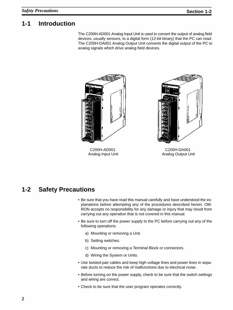
The C200H-AD001 Analog Input Unit is used to convert the output of analog fielddevices, usually sensors, to a digital form (12-bit binary) that the PC can read.The C200H-DA001 Analog Output Unit converts the digital output of the PC toanalog signals which drive analog field devices.
C200H-AD001 Analog Input Unit
C200H-DA001 Analog Output Unit
1-2 Safety Precautions
• Be sure that you have read this manual carefully and have understood the ex-planations before attempting any of the procedures described herein. OM-RON accepts no responsibility for any damage or injury that may result fromcarrying out any operation that is not covered in this manual.
• Be sure to turn off the power supply to the PC before carrying out any of thefollowing operations:
a) Mounting or removing a Unit.
b) Setting switches.
c) Mounting or removing a Terminal Block or connectors.
d) Wiring the System or Units.
• Use twisted-pair cables and keep high-voltage lines and power lines in sepa-rate ducts to reduce the risk of malfunctions due to electrical noise.
• Before turning on the power supply, check to be sure that the switch settingsand wiring are correct.
• Check to be sure that the user program operates correctly.
Safety Precautions Section 1-2

3
1-3 Basic ConfigurationThis diagram shows some of the possible field devices for the Analog I/OUnits. Any I/O device can be used as long as voltage/current requirementsfall within the specified ranges.
The I/O device connected to the Analog I/O Unit will often serve as an inter-face for another device. For example, a preamplifier may amplify the outputof a pressure gauge to the level required for the Analog Input Unit and a reg-ulator may interface a heating system to control temperature.
Preamp
Transducer
Variablespeed controller
Servo-controller
M
M
TemperaturePressureSpeedFlow rate
VoltageCurrentPowerPower factor
AnalogOutput Unit
Regulator
(Temperaturecontrol)
(Speed control)
(Position control)
C200H CPU Rack
AnalogInput Unit
Chart recorder
Basic Configuration Section 1-3

4
1-4 Example Configurations
Below are two examples of how Analog I/O Units can be used in control sys-tems. The first diagram shows a temperature regulating system and the sec-ond shows a servomotor positioning system.
ÇÇÇÇÇÇÇÇ
ÇÇÇÇÇÇÇÇ
Sensor
Servo motor
Servocontroller
Locating pulse
M
PlatformSYSMACC200HS/C200H/C200HX/HG/HE
ÇÇÇÇÇÇÇÇ
Analog Output UnitC200H-DA001
Analog Input UnitC200H-AD001
High-speed Counter UnitC200H-CT001-V1
Encoder
Fuel
Transducer
M
SYSMACC200HS/C200H/C200HX/HG/HE
Valve controller
Analog Input UnitC200H-AD001
Analog Output UnitC200H-DA001
Temperature sensingelement
Example Configurations Section 1-4
5
1-5 System Considerations
Number of Units C200HS/C200H/C200HX/HG/HE Analog I/O Units are classified as Special I/OUnits. A maximum total of ten Special I/O Units (including PC Link Units) can bemounted to the CPU Rack, Expansion I/O Racks, and Slave Racks of a singlePC. A single C200H-NC211 Position Control Unit counts as two Units.
The Units that belong to the various Special I/O Unit groups are shown in thefollowing table. Their usage is limited according to the maximum current pro-vided for the Rack and the amount of current consumed by each Unit. For de-tails, refer to the C200HS/C200H Installation Guide.
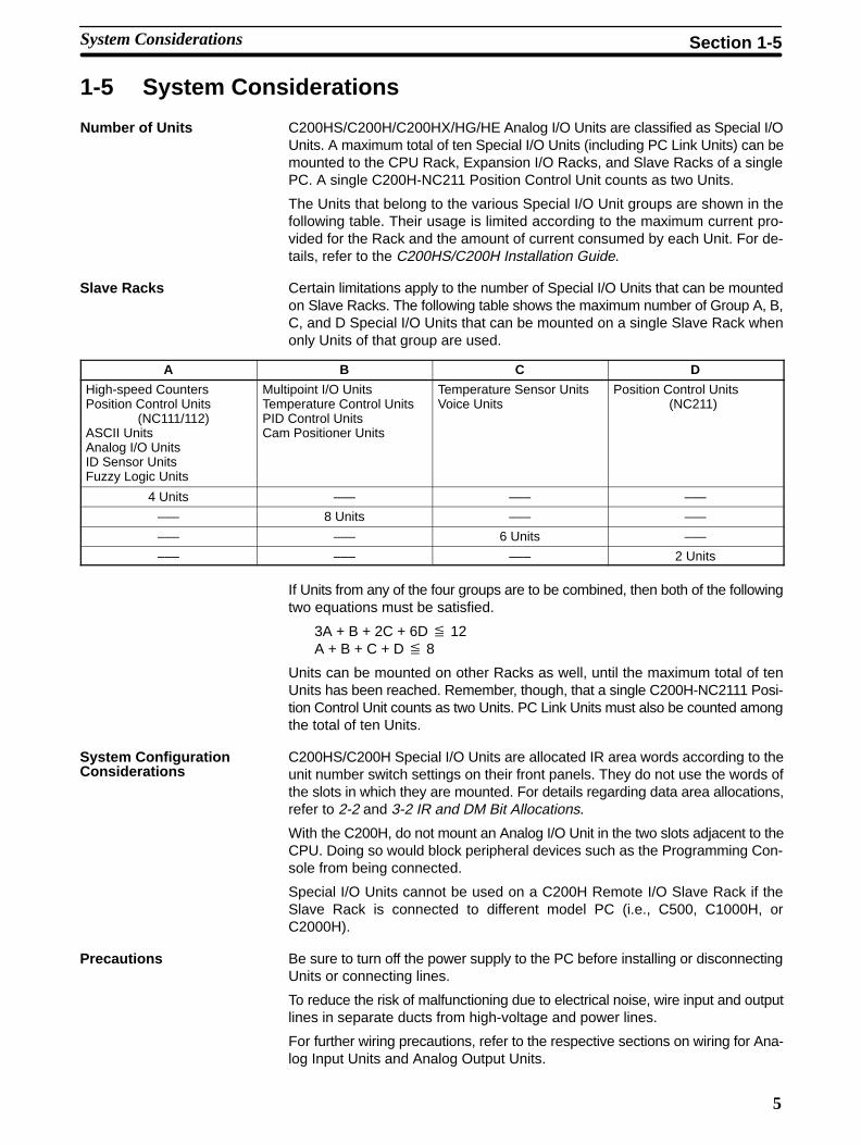
Certain limitations apply to the number of Special I/O Units that can be mountedon Slave Racks. The following table shows the maximum number of Group A, B,C, and D Special I/O Units that can be mounted on a single Slave Rack whenonly Units of that group are used.
A B C D
High-speed CountersPosition Control Units
(NC111/112)ASCII UnitsAnalog I/O UnitsID Sensor UnitsFuzzy Logic Units
Multipoint I/O UnitsTemperature Control UnitsPID Control UnitsCam Positioner Units
Temperature Sensor UnitsVoice Units
Position Control Units (NC211)
4 Units ––– ––– –––
––– 8 Units ––– –––
––– ––– 6 Units –––
––– ––– ––– 2 Units
If Units from any of the four groups are to be combined, then both of the followingtwo equations must be satisfied.
3A + B + 2C + 6D x 12A + B + C + D x 8
Units can be mounted on other Racks as well, until the maximum total of tenUnits has been reached. Remember, though, that a single C200H-NC2111 Posi-tion Control Unit counts as two Units. PC Link Units must also be counted amongthe total of ten Units.
C200HS/C200H Special I/O Units are allocated IR area words according to theunit number switch settings on their front panels. They do not use the words ofthe slots in which they are mounted. For details regarding data area allocations,refer to 2-2 and 3-2 IR and DM Bit Allocations.
With the C200H, do not mount an Analog I/O Unit in the two slots adjacent to theCPU. Doing so would block peripheral devices such as the Programming Con-sole from being connected.
Special I/O Units cannot be used on a C200H Remote I/O Slave Rack if theSlave Rack is connected to different model PC (i.e., C500, C1000H, orC2000H).
Be sure to turn off the power supply to the PC before installing or disconnectingUnits or connecting lines.
To reduce the risk of malfunctioning due to electrical noise, wire input and outputlines in separate ducts from high-voltage and power lines.
For further wiring precautions, refer to the respective sections on wiring for Ana-log Input Units and Analog Output Units.
Slave Racks
System ConfigurationConsiderations
Precautions
System Considerations Section 1-5

7
SECTION 2C200H-AD001 Analog Input Unit
This section provides the information required to install and operate a C200H-AD001 Analog Input Unit.
2-1 Before Operation 8 . . . . . . . . . . . . . . . . . . . . . . . . . . . . . . . . . . . . . . . . . . . . . . . . . . 2-1-1 Nomenclature and Functions 8 . . . . . . . . . . . . . . . . . . . . . . . . . . . . . . . . . 2-1-2 Switch Settings 10 . . . . . . . . . . . . . . . . . . . . . . . . . . . . . . . . . . . . . . . . . . . 2-1-3 Wiring 11 . . . . . . . . . . . . . . . . . . . . . . . . . . . . . . . . . . . . . . . . . . . . . . . . . .
2-2 Bit and DM Area Allocations 15 . . . . . . . . . . . . . . . . . . . . . . . . . . . . . . . . . . . . . . . . . 2-3 Functions and Programming 18 . . . . . . . . . . . . . . . . . . . . . . . . . . . . . . . . . . . . . . . . .
2-3-1 Input Signal Range Setting 19 . . . . . . . . . . . . . . . . . . . . . . . . . . . . . . . . . . 2-3-2 Square Root 19 . . . . . . . . . . . . . . . . . . . . . . . . . . . . . . . . . . . . . . . . . . . . . . 2-3-3 Scaling 20 . . . . . . . . . . . . . . . . . . . . . . . . . . . . . . . . . . . . . . . . . . . . . . . . . . 2-3-4 Mean Value 21 . . . . . . . . . . . . . . . . . . . . . . . . . . . . . . . . . . . . . . . . . . . . . . 2-3-5 Peak Value 22 . . . . . . . . . . . . . . . . . . . . . . . . . . . . . . . . . . . . . . . . . . . . . . . 2-3-6 Input Disconnection Detection 23 . . . . . . . . . . . . . . . . . . . . . . . . . . . . . . . 2-3-7 Data Setting Example and Programming Concepts 23 . . . . . . . . . . . . . . .
2-4 Troubleshooting 26 . . . . . . . . . . . . . . . . . . . . . . . . . . . . . . . . . . . . . . . . . . . . . . . . . . .
8
2-1 Before Operation
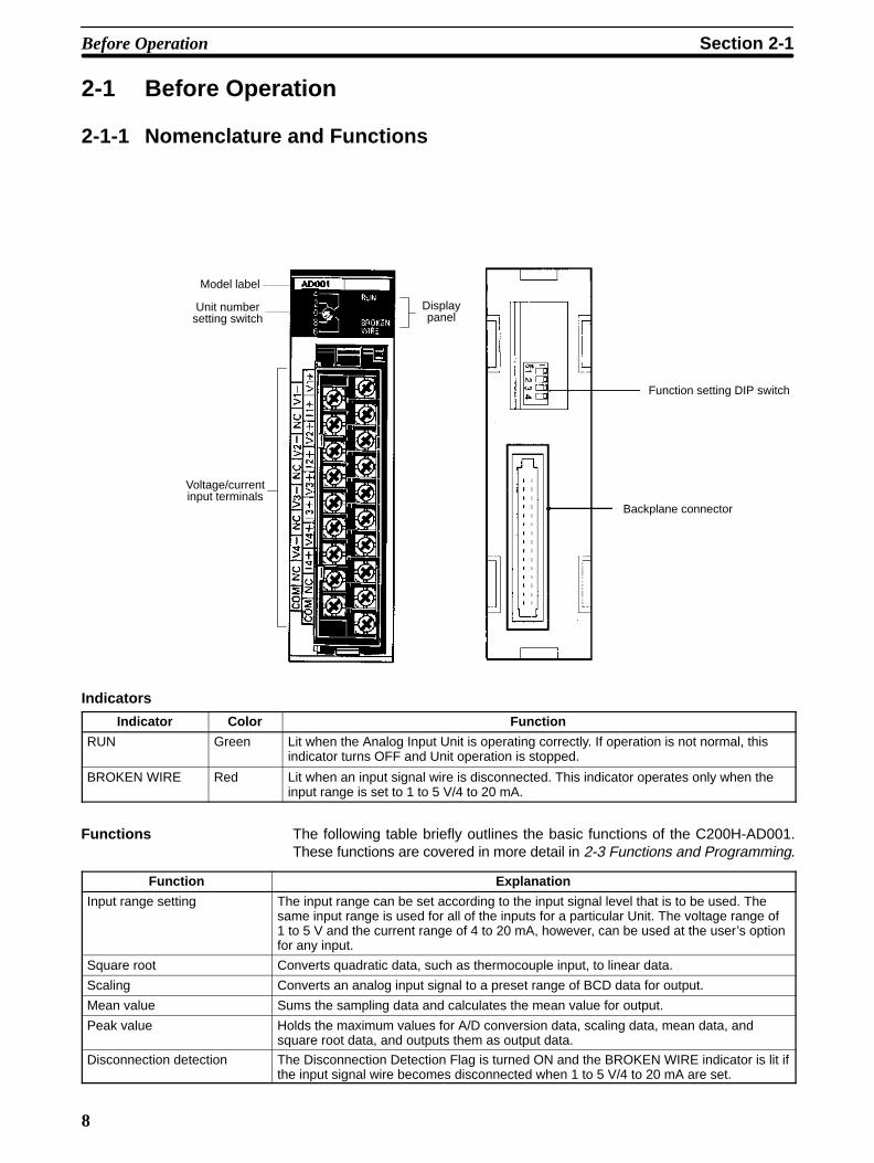
2-1-1 Nomenclature and Functions
Displaypanel
Voltage/currentinput terminals
Unit numbersetting switch
Model label
Function setting DIP switch
Backplane connector
Indicators
Indicator Color Function
RUN Green Lit when the Analog Input Unit is operating correctly. If operation is not normal, thisindicator turns OFF and Unit operation is stopped.
BROKEN WIRE Red Lit when an input signal wire is disconnected. This indicator operates only when theinput range is set to 1 to 5 V/4 to 20 mA.
The following table briefly outlines the basic functions of the C200H-AD001.These functions are covered in more detail in 2-3 Functions and Programming.
Function Explanation
Input range setting The input range can be set according to the input signal level that is to be used. Thesame input range is used for all of the inputs for a particular Unit. The voltage range of1 to 5 V and the current range of 4 to 20 mA, however, can be used at the user’s optionfor any input.
Square root Converts quadratic data, such as thermocouple input, to linear data.
Scaling Converts an analog input signal to a preset range of BCD data for output.
Mean value Sums the sampling data and calculates the mean value for output.
Peak value Holds the maximum values for A/D conversion data, scaling data, mean data, andsquare root data, and outputs them as output data.
Disconnection detection The Disconnection Detection Flag is turned ON and the BROKEN WIRE indicator is lit ifthe input signal wire becomes disconnected when 1 to 5 V/4 to 20 mA are set.
Functions
Before Operation Section 2-1

9
The following diagram shows the basic internal configuration of the Unit.
Rangeselector
Multi-plexer
A/Dconverter
Photo-coupler
Photo-coupler
Analog power supply
+5 V
0 V
DC/DC
Businter-face
converter
C200HorC200HSPC
I/O bus
CPU
ROM/RAM
+Voltage Input
+Current Input
–Input
Analog 0 V
+Voltage Input
+Current Input
–Input
+Voltage Input
+Current Input
–Input
+Voltage Input
+Current Input
–Input
Watchdogtimer
Common
SW
Inpu
t poi
nt 1
Inpu
t poi
nt 2
Inpu
t poi
nt 3
Inpu
t poi
nt 4
Block Diagram
Before Operation Section 2-1
10
2-1-2 Switch SettingsThere are four settings necessary for this Unit: unit number, number of in-puts, input range, and data reading mode.
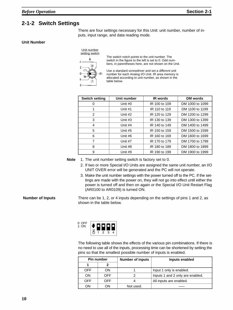
Unit Number
Unit numbersetting switch
The switch notch points to the unit number. Theswitch in the figure to the left is set to 0. Odd num-bers, in parentheses here, are not shown on the Unit.
Use a standard screwdriver and set a different unitnumber for each Analog I/O Unit. IR area memory isallocated according to unit number, as shown in thetable below.
Switch setting Unit number IR words DM words
0 Unit #0 IR 100 to 109 DM 1000 to 1099
1 Unit #1 IR 110 to 119 DM 1100 to 1199
2 Unit #2 IR 120 to 129 DM 1200 to 1299
3 Unit #3 IR 130 to 139 DM 1300 to 1399
4 Unit #4 IR 140 to 149 DM 1400 to 1499
5 Unit #5 IR 150 to 159 DM 1500 to 1599
6 Unit #6 IR 160 to 169 DM 1600 to 1699
7 Unit #7 IR 170 to 179 DM 1700 to 1799
8 Unit #8 IR 180 to 189 DM 1800 to 1899
9 Unit #9 IR 190 to 199 DM 1900 to 1999
Note 1. The unit number setting switch is factory set to 0.2. If two or more Special I/O Units are assigned the same unit number, an I/O
UNIT OVER error will be generated and the PC will not operate.3. Make the unit number settings with the power turned off to the PC. If the set-
tings are made with the power on, they will not go into effect until either thepower is turned off and then on again or the Special I/O Unit Restart Flag(AR0100 to AR0109) is turned ON.
There can be 1, 2, or 4 inputs depending on the settings of pins 1 and 2, asshown in the table below.
0: OFF1: ON
The following table shows the effects of the various pin combinations. If there isno need to use all of the inputs, processing time can be shortened by setting thepins so that the smallest possible number of inputs is enabled.
Pin number Number of inputs Inputs enabled
1 2
p p
OFF ON 1 Input 1 only is enabled.
ON OFF 2 Inputs 1 and 2 only are enabled.
OFF OFF 4 All inputs are enabled.
ON ON Not used. –––
Number of Inputs
Before Operation Section 2-1

11
Use pin 3 to set the input range.
Pin number 3 Input rangeOFF Voltage input 1 to 5 V
Current input 4 to 20 mA
ON Voltage input 0 to 10 V
Note The same input range is used for all of the inputs for a particular Unit. The voltagerange of 1 to 5 V and the current range of 4 to 20 mA, however, can be used at theuser’s option at any input.
In normal mode, the input data is read only once before being converted fromanalog to digital. In filter mode, the input data is read three times and thenthe average values are converted from analog to digital. This helps to reducethe effects of electrical noise and so on. Using filter mode, however, results inlonger processing time, as shown in the following table.
Pin number 3 Data reading mode A/D conversion time
OFF Normal mode 2.5 ms/input max.
ON Filter mode 4 ms/input
2-1-3 Wiring
The following illustration shows the function of each terminal.
A0
A2
A4
A6
A8
B0
B2
B4
B6
B9
B1
B3
B5
B7
B8A7
A5
A3
A1
Input 1 (–)
Not used.
Input 2 (–)
Not used.
Input 3 (–)
Not used.
Input 4 (–)
Not used.
Common (Analog 0 V)
Voltage input 1 (+)
Current input 1 (+)
Voltage input 2 (+)
Current input 2 (+)
Voltage input 3 (+)
Current input 3 (+)
Voltage input 4 (+)
Current input 4 (+)
Not used.
Common (Analog 0 V)
The same input range is used for all of the inputs for a particular Unit. The voltagerange of 1 to 5 V and the current range of 4 to +20 mA, however, can be used atthe user’s option at any input.
Use the DIP switch on the back panel of the Unit to set the input range and thenumber of inputs. (For details, refer to 2-1-2 Switch Settings.)
When current input is used, short circuit the voltage input (+) and current input(+) terminals.
The common terminal is connected to the 0 V of the Analog Input Unit’s analogcircuit. Noise interference can be reduced by using shielded cables for inputlines.
The A8 and B9 terminals are short circuited internally.
Input Range
Data Reading Mode
Terminal Allocation
Before Operation Section 2-1

12
The following diagram illustrates the external wiring of voltage inputs for theC200H-AD001.
Input 1
Input 2
Input 3
Input 4
Shield
C200H-AD001
0 V
0 V
0 V
0 V
Input side
Note Terminals A8 and B9 are analog input ground terminals. They are not framegrounds and so do not connect them to a ground.
Voltage Inputs
Before Operation Section 2-1

13
The following diagram illustrates the external wiring of current inputs for theC200H-AD001. When current inputs are used, use the short pins provided withthe Unit to short circuit the V+ and I+ terminals as shown in the diagram.
Input 1
Input 2
Input 3
Input 4
Shield
C200H-AD001
0 V
+ V
0 V
+ V
0 V
+ V
0 V
+ V
(Short pin)
Input side
(Short pin)
(Short pin)
(Short pin)
Note Terminals A8 and B9 are analog input ground terminals. They are not framegrounds and so do not connect them to a ground.
Current Inputs
Before Operation Section 2-1

14
When wiring inputs, apply the following points to avoid noise interference andoptimize Analog Input Unit performance.
• Use shielded twisted-pair cable for external connections and power lines.
• Route input cables separately from the AC cable, and do not run the Unit’scables near a main circuit cable, high voltage cable, or a non-PC load cable.
• Be sure to install surge-absorbing diodes or surge absorbers for inductiveloads (relays, solenoids, electromagnetic valves, etc.) They should beinstalled right next to relays and solenoids. Use surge-absorbing diodes with adielectric strength of at least five times the circuit voltage.
DC Relay
Surge-absorbing diode(Example: ERB44-06,by Fuji Electric)
Solenoid, etc.
AC Relay
Surge absorber
Surge absorber
• If there is noise interference from power lines (if, for example, the power supplyis shared with electrical welding devices or electrical discharge machines, or ifthere is a high-frequency generation source nearby) install a noise filter at thepower supply input area.
• Use at least a class-3 ground (to 100 Ω or less), with as heavy a wire as pos-sible (i.e., at least 1.25 mm2).
Input WiringConsiderations
Before Operation Section 2-1

15
2-2 Bit and DM Area Allocations
IR Area Allocation C200H Analog Input Units are allocated ten words each from the portion of theIR area (IR 100 to IR 199) that is reserved for Special I/O Units. The words thatare allocated a particular Analog Input Unit depend on the setting of the unitnumber on the front panel of the Unit. Those ten words are then reserved as anI/O refresh data area, and the bits that comprise that area are refreshed with ev-ery I/O refresh scan by the PC.
IR n + 1toIR n +5
IR n
IR 130 to 139
IR 140 to 149
IR 150 to 159
IR 100 to 109
IR 110 to 119
IR 120 to 129
IR 190 to 199
IR 160 to 169
IR 170 to 179
IR 180 to 189
SYSMAC C200HS/C200H/C200HX/HG/HE PC C200H-AD001 Analog Input Unit
IN refresh
(I/O refresh data area)
(n = 100 + 10 x unit number)
Unit #0
Unit #1
Unit #2
Unit #3
Unit #4
Unit #5
Unit #6
Unit #7
Unit #8
Unit #9
(Work area)
At the I/O refresh by thePC, outputs (PC to Unit)and inputs (Unit to PC)are refreshed in orderwith every scan.
The OUT and IN refreshes are as seen fromthe PC.
OUT refresh
Note The unit number that is set for an Analog Input Unit must not be used for anyother Special I/O Unit. If the same unit number is set more than once, an I/OUNIT OVER error will be generated and operation will be stopped.
DM Area Allocation
DM (m + 8)toDM (m +11)
DM (m) to DM (m+ 7)
DM 1900 to 1911
DM 1800 to 1811
DM 1700 to 1711
DM 1600 to 1611
DM 1500 to 1511
DM 1400 to 1411
DM 1300 to 1311
DM 1200 to 1211
DM 1100 to 1111
DM 1000 to 1011Unit #0
SYSMAC C200HS/C200H/C200HX/HG/HE PC C200H-AD001 Analog Input Unit
(Fixed data area)
Scaling data
Mean dataAutomatically transferredto each unit at power upor when Special I/O Re-start Flag is turned ON.
Unit #1
Unit #2
Unit #3
Unit #4
Unit #5
Unit #6
Unit #7
Unit #8
Unit #9(m = 1000 + 100 x unit number)
(For more information regarding DM area allocation, refer to DMAllocations at the end of this section.)
(DM area)
Bit and DM Area Allocations Section 2-2

16
IR Allocations
I/O Wd(IR)
Bit(IR) 15 14 13 12 11 10 09 08 07 06 05 04 03 02 01 00
OUT n 0 0 0 SQ PK Mean value processing 0 Scaling execution OA CPQ
Input 4 Input 3 Input 2 Input 1 Input 4 Input 3 Input 2 Input 1
IN n+1 Input 1 A/D conversion data or processing data
n+2 Input 2 A/D conversion data or processing data
n+3 Input 3 A/D conversion data or processing data
n+4 Input 4 A/D conversion data or processing data
n+5 0 0 0 0 0 0 0 OD Input pts.00: 4 pts.
IR Disconnection detection SE00: 4 ts.01: 2 pts.10: 1 pt.
Input 4 Input 3 Input 2 Input 1
n+6to
n+9Not used.
Note The following abbreviations are used in this table. SQ: square root calculation;PK: peak value; OA: offset adjustment; CP: A/D conversion prohibited; OD: out-puts disabled; IR: input range; SE: setting error.
A/D Conversion Data
Input range Binary data
0 to 10 V, 1 to 5 V, 4 to 20 mA 0000 to 0FA0
When scaling, mean value processing, peak value, or square root calculation isexecuted, the resulting data is output.
Note When scaling is executed, it is set in words n+1 through n+4 in BCD.
IR Area Contents: Outputs
Address Item Contents
Word(IR)
Bit
15 to 13 ––– Not used. Set each bit to 0 (i.e., OFF).
12 Square Root ON Bit Turn this bit ON (i.e., set it to 1) to execute the square rootcalculation. It is used for all inputs.
11 Peak Value ON Bit Turn this bit ON (i.e., set it to 1) to execute the peak valuefunction. It is used for all inputs.
n 10 to 07 Mean Value ON Bit Turn these bits ON (i.e., set them to 1) to calculate the meanvalues for the respective inputs. Bits 07 to 10 correspond toinputs 1 to 4.
06 ––– Not used. Set to 0 (i.e., OFF).
05 to 02 Scaling ON Bit Turn these bits ON (i.e., set them to 1) to execute scaling for therespective inputs. Bits 02 to 05 correspond to inputs 1 to 4.
01 Offset adjustment Turn this bit ON (i.e., set it to 1) to execute the offset adjustment.The adjustment is carried out automatically at power up, so thisbit does not normally need to be used.
00 A/D conversion prohibition Turn this bit ON (i.e., set it to 1) to prohibit A/D conversion. It isused for all inputs.
Processing Data
Bit and DM Area Allocations Section 2-2

17
IR Area Contents: Inputs
Word(IR)
Bit Item Contents
n+1 15 to 00 Input 1 A/D conversion dataor processing data
The A/D conversion data (binary) is set here for each input. (Thedata is set in BCD for scaling.)
n+2 15 to 00 Input 2 A/D conversion dataor processing data
g )
n+3 15 to 00 Input 3 A/D conversion dataor processing data
n+4 15 to 00 Input 4 A/D conversion dataor processing data
15 to 09 ––– Not used.
08 Output disabled Conversion data is unstable at power up, so this bit prohibits A/Dconversion data from being output. It remains ON forapproximately 100 ms after the power is turned on.
07 to 06 Number of inputs The number of inputs (4, 2, or 1) is determined by the status ofpin numbers 1 and 2 of the DIP switch on the rear panel of theAnalog Input Unit. The status of pin 2 affects bit 07, and thestatus of pin 1 affects bit 06.
n+5 05 Input range The status of this bit reflects the setting of pin 3 of the rear-panelDIP switch.
04 to 01 Input Disconnect Flag When an input is disconnected, the corresponding bit is turnedON (i.e., is set to 1). Bits 01 to 04 correspond to inputs 1 to 4respectively. (See note 1.)
00 Setting Error Flag This bit turns ON (i.e., is set to 1) if the data set in the DM area iswrong. (See note 2.)
Note 1. This bit turns ON under the following conditions:
• An input is 0.5 V or less when set for 1 to 5V.
• An input is 2 mA or less when set for 4 to 20 mA.
• The input does not function when set for 0 to 10 V.
2. The Setting Error Flag turns ON when the scaling upper and lower limits arenot in BCD or when the number of mean processing terms is 0000 or not inBCD.
3. Even if scaling or mean processing are not executed, and regardless ofwhether or not inputs are used, the data described in note 2 will cause theSetting Error Flag to turn ON. This will have no effect on operation, however.
4. n = 100 + 10 x unit number
DM Allocations
Word Bit
15 14 13 12 11 10 09 08 07 06 05 04 03 02 01 00
DM (m) Input 1, scaling lower limit data
DM (m+1) Input 1, scaling upper limit data
DM (m+2) Input 2, scaling lower limit data
DM (m+3) Input 2, scaling upper limit data
DM (m+4) Input 3, scaling lower limit data
DM (m+5) Input 3, scaling upper limit data
DM (m+6) Input 4, scaling lower limit data
DM (m+7) Input 4, scaling upper limit data
DM (m+8) Input 1, number of samples for mean processing
DM (m+9) Input 2, number of samples for mean processing
DM (m+10) Input 3, number of samples for mean processing
DM (m+11) Input 4, number of samples for mean processing
Bit and DM Area Allocations Section 2-2

18
Note 1. The DM area that is used is a read-only area, so the data cannot be writtenfrom the program. Use the Programming Console to set data by changingthe present value or changing three words together.
2. The range for setting scaling data is 0000 to 9999 (BCD). Make sure that thelower limit is smaller than the upper limit.
3. The range for setting the number of times that sampling is to be executed formean value processing is 0002 to 9999 (BCD).
4. Data that is set in the DM area is transferred either at the time of power up orwhen the Special I/O Unit Restart Bit is turned ON. Any data that is set in themeantime will remain invalid until then.
DM Contents
Words Bits Item Data contents
DM (m) to DM (m+7) 15 to 00 Scaling data The scaling data (upper and lower limits) is set inBCD (0000 to 9999), using two words for eachinput. Set the lower limit in the rightmost word andthe upper limit in the leftmost word, and make surethat the lower limit is smaller than the upper limit.
DM (m+8) to DM (m+11) 15 to 00 Number of terms forcalculating mean value
The number of samples to be taken for calculatingthe mean value is set in BCD (0002 to 9999) foreach input. DM words m+8 through m+11correspond to inputs 1 to 4.
2-3 Functions and ProgrammingThe C200H-AD001 Analog Input Unit provides six functions:
• Input signal range setting
• Square root
• Scaling
• Mean value
• Peak value
• Input disconnection detection
These functions are set using Unit switches and Peripheral Devices, such as aProgramming Console. The words allocated to the Unit in the DM Area (DM m toDM m+11) cannot be written from user program and all data set in these wordsmust be written from a Peripheral Device.
When inputting data from a Programming Console, use the operations tochange present values. When inputting from the SSS (SYSMAC Support Soft-ware), use the DM editing operations.
The data set in the DM area is transferred to the Analog Input Unit when either ofthe following steps is taken. Be sure to perform one or the other of these stepswhenever new data has been set or data has been changed.
• Turning ON the power to the C200H/C200HS/C200HX/HG/HE CPU.
• Turning ON the Restart Bit allocated to the Unit as a Special I/O Unit (AR 0100to 0109).
Any or all of the six functions can be used at the same time. Data will be pro-cessed in the following sequence and the final results will be output to words n+1to n+4: analog-to-digital conversion → square root → scaling → mean value →peak value.
Functions and Programming Section 2-3
19
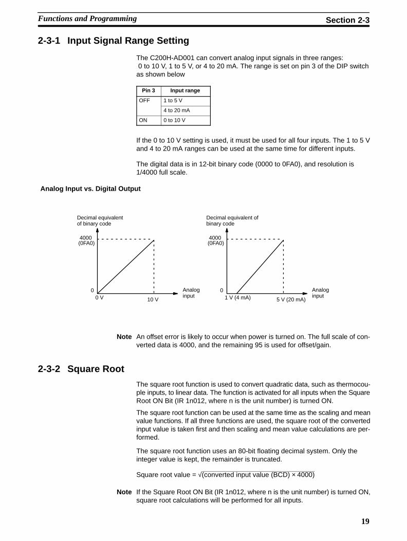
2-3-1 Input Signal Range Setting
The C200H-AD001 can convert analog input signals in three ranges: 0 to 10 V, 1 to 5 V, or 4 to 20 mA. The range is set on pin 3 of the DIP switchas shown below
Pin 3 Input range
OFF 1 to 5 V
4 to 20 mA
ON 0 to 10 V
If the 0 to 10 V setting is used, it must be used for all four inputs. The 1 to 5 Vand 4 to 20 mA ranges can be used at the same time for different inputs.
The digital data is in 12-bit binary code (0000 to 0FA0), and resolution is1/4000 full scale.
Analog Input vs. Digital Output
00 V 10 V
Analoginput
Decimal equivalentof binary code
01 V (4 mA) 5 V (20 mA)
Analoginput
Decimal equivalent ofbinary code
4000(0FA0)
4000(0FA0)
Note An offset error is likely to occur when power is turned on. The full scale of con-verted data is 4000, and the remaining 95 is used for offset/gain.
2-3-2 Square Root
The square root function is used to convert quadratic data, such as thermocou-ple inputs, to linear data. The function is activated for all inputs when the SquareRoot ON Bit (IR 1n012, where n is the unit number) is turned ON.
The square root function can be used at the same time as the scaling and meanvalue functions. If all three functions are used, the square root of the convertedinput value is taken first and then scaling and mean value calculations are per-formed.
The square root function uses an 80-bit floating decimal system. Only theinteger value is kept, the remainder is truncated.
Square root value = √(converted input value (BCD) × 4000)
Note If the Square Root ON Bit (IR 1n012, where n is the unit number) is turned ON,square root calculations will be performed for all inputs.
Functions and Programming Section 2-3
20
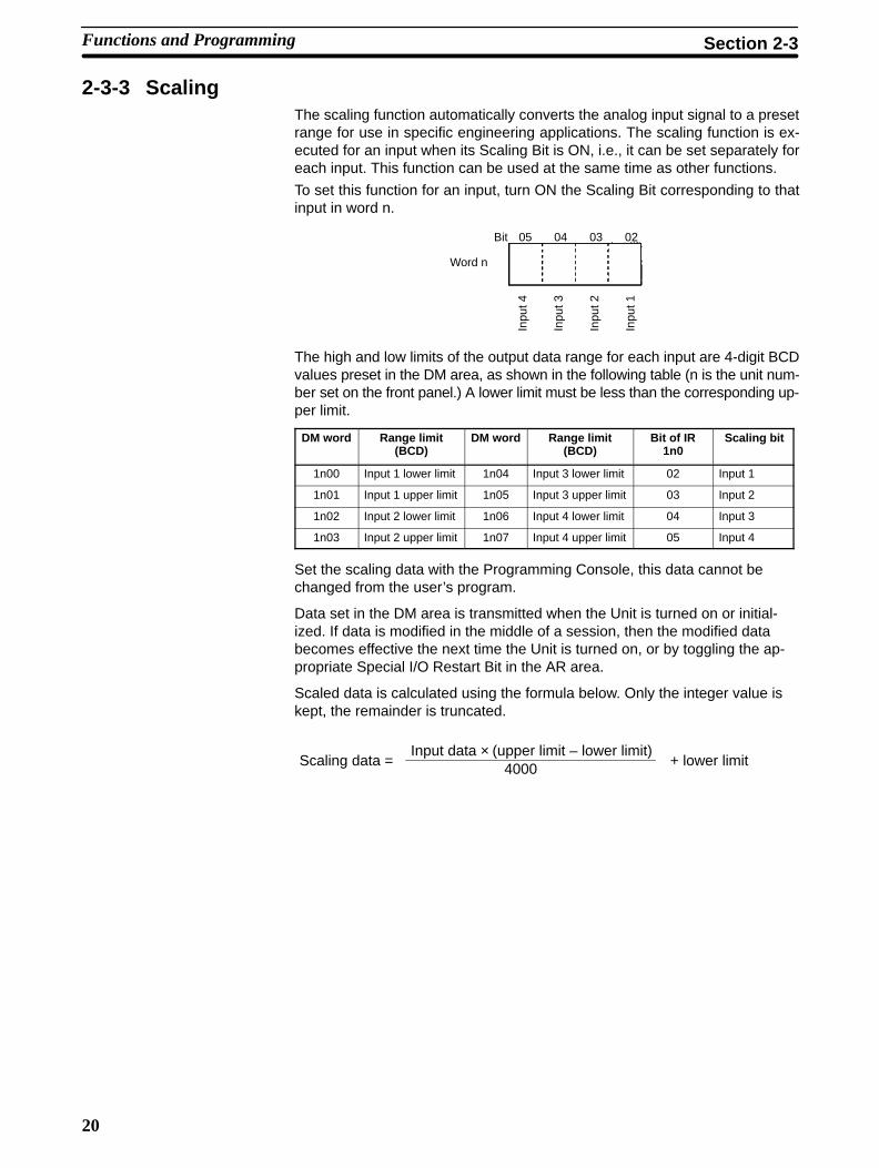
2-3-3 ScalingThe scaling function automatically converts the analog input signal to a presetrange for use in specific engineering applications. The scaling function is ex-ecuted for an input when its Scaling Bit is ON, i.e., it can be set separately foreach input. This function can be used at the same time as other functions.
To set this function for an input, turn ON the Scaling Bit corresponding to thatinput in word n.
Bit 05 04 03 02
Word n
Inpu
t 4
Inpu
t 3
Inpu
t 2
Inpu
t 1
The high and low limits of the output data range for each input are 4-digit BCDvalues preset in the DM area, as shown in the following table (n is the unit num-ber set on the front panel.) A lower limit must be less than the corresponding up-per limit.
DM word Range limit(BCD)
DM word Range limit(BCD)
Bit of IR1n0
Scaling bit
1n00 Input 1 lower limit 1n04 Input 3 lower limit 02 Input 1
1n01 Input 1 upper limit 1n05 Input 3 upper limit 03 Input 2
1n02 Input 2 lower limit 1n06 Input 4 lower limit 04 Input 3
1n03 Input 2 upper limit 1n07 Input 4 upper limit 05 Input 4
Set the scaling data with the Programming Console, this data cannot bechanged from the user’s program.
Data set in the DM area is transmitted when the Unit is turned on or initial-ized. If data is modified in the middle of a session, then the modified databecomes effective the next time the Unit is turned on, or by toggling the ap-propriate Special I/O Restart Bit in the AR area.
Scaled data is calculated using the formula below. Only the integer value iskept, the remainder is truncated.
Input data × (upper limit – lower limit)4000Scaling data = + lower limit
Functions and Programming Section 2-3

21
Example An example is shown below.
Input signal range: 0 to 10 VLower limit: 1000Upper limit: 9000
Scaled dataNormal data
0 V 5 V 10 VInput signal
If a 5-V input is received, it would be converted to 2000 (5/10 x 4000) and thenscaled as shown below.
2000 × (9000 – 1000)4000Scaling data = + 1000 = 5000
Note 1. Scaling will not be performed and unscaled (normal) data will be output if thecontents of DM words allocated to the Unit is not BCD or if a lower limit isgreater than the corresponding upper limit.
2. The Setting Error Flag (bit 00 in IR 1n5, where n is the unit number) will beturned ON if the contents of DM m to DM m+7 is not BCD.
3. The Setting Error Flag will turn ON whenever DM area data is not BCD re-gardless of whether an input is being used and regardless of whether or notscaling is set. Operation, however, will be normal in these cases.
Resolution If the difference between an upper limit and the corresponding lower limit (upperlimit – lower limit) is 4000 or greater, the resolution is fixed at 1/4000. If the differ-ences is less than 4000, the resolution will be reduced proportionately.
For example, if the upper limit minus the lower limit is 2000, the resolution is1/2000.
2-3-4 Mean ValueThe mean value function sums a specified number of terms of converted inputdata and divides by the number of terms preset the DM area.
If the Mean ON Bit for an input is ON (bits 07 to 10 of word n), the mean value willbe output to the corresponding word in the PC. The desired number of termsmust be set in the corresponding word in the DM area between DM m+8 andDM m+11. The setting can be between 0002 and 9999 (BCD).
Bit 10 09 08 07
Word n
Inpu
t 4
Inpu
t 3
Inpu
t 2
Inpu
t 1
Functions and Programming Section 2-3

22
The mean value functions can be used in combination with any of the other func-tions.
Set the mean data for each input with the Programming Console. This datacannot be changed from the user’s program. Set the mean data for all 4 in-puts even when using only one input. If there is a mistake in the data foreven 1 input, the Setting Error Flag will be activated, though operation willcontinue.
The mean value is calculated using the formula below. When the Mean En-able Bit turns ON, the converted data will read “0000” until the mean value iscalculated for the first time.
Sum of converted input valuesNumber of terms (mean data)
Mean value =
The maximum mean function conversion time = 2.5 ms × the sum of thenumber of terms for all inputs
Note 1. Mean value calculation will not be performed and normal data will be outputif the number of terms set in the DM area is 0000 or is not BCD.
2. The Setting Error Flag (bit 00 in IR 1n5, where n is the unit number) will beturned ON if the number of terms set in the DM area is 0000 or is not BCD.
3. The Setting Error Flag will turn ON whenever the number of terms set in theDM area is 0000 or is not BCD regardless of whether an input is being usedand regardless of whether or not scaling is set. Operation, however, will benormal in these cases.
2-3-5 Peak ValueThe peak value function holds the maximum output value for every input. Thisfunction can be used at the same time an any or all of the other functions.
The output value that will be held is one of the following depending on what otherfunctions are set: converted input value, scaled value, mean value, and squareroot. Data will be processed in the following sequence and the maximum valueof the final results will be output to words n+1 to n+4: analog-to-digital conver-sion → square root → scaling → mean value → peak value.
The peak value function is activated for all 4 inputs when the Peak Value ON Bit(IR 1n011, where n is the unit number) is turned ON and reset when it is turnedOFF.
Note If the Peak Value ON Bit (IR 1n011, where n is the unit number) is turned ON, thepeak value will be held for all inputs.
Functions and Programming Section 2-3

23
Mean and Peak Values Data will be output as illustrated below when both the mean value and the peakvalue functions are used. In this example, mean value #2 will be output as thefirst peak value even if mean value #1 is larger because the Peak Value ON Bitwas turned ON after mean value #1 was output.
Meanvalue
Peak ValueON Bit
Output value
ON
OFF
Results #1 Results #2 Results #3 Results #4
Mean value #1 Mean value #2 Mean value #3 Mean value #4 Mean value #5
Previous mean value Mean value #1 Mean value #2 (1st peak value)
Larger of meanvalues #2 and #3
Largest of meanvalues #2 to #4
2-3-6 Input Disconnection DetectionThe Input Disconnect Flags will be turned ON when an the input signal level isless than 0.5 V/2 mA and the input signal range is set at 1 to 5 V/4 to 20 mA.These flags will not turn ON when the input signal range is set at 0 to 10 V.
The Input Disconnect Flags are contained in in word IR n+5, as shown below.
Bit 04 03 02 01
Word n +5
Inpu
t 4
Inpu
t 3
Inpu
t 2
Inpu
t 1
The BROKEN WIRE indicator on the Analog Input Unit will light whenever any ofthe Input Disconnect Flags turn ON.
Note 1. The Input Disconnect Flags will operate only when the Conversion Inhibit Bit(bit 00 of IR n) is OFF.
2. Input disconnection is detected for all input set on pins 1 and 2 of the back-panel DIP switch. If an input that is not being used (i.e., not connected) isspecified on the DIP switch, the Input Disconnect Flag will turn ON.
3. The current peak value will be held even if a disconnected input is detected.
2-3-7 Data Setting Example and Programming Concepts
Data SettingsThe following settings are used in this example. Data in the DM area is set usingthe SSS, a Programming Console, or another Peripheral Device.
Basic Settings Turn power to the PC off then then back on or turn ON the Special I/O Unit Re-start Bit allocated to the Unit (AR 0100 to AR 0109) after setting the data so thatthe data is read into the Analog Input Unit.
Item Setting
Unit number 0 (allocated words: IR 100 to IR 109 and DM 1000 to DM 1011)
Inputs used Inputs 1 to 4
Functions and Programming Section 2-3

24
Details
Item Input 4 Input 3 Input 2 Input 1
Input signal range 1 to 5 V 4 to 20 mA 1 to 5 V 1 to 5 V
Scaling Lower limit ––– 0400 1000 1000g
Upper limit ––– 1000 5000 5000
Number of terms formean value calculation
––– 50 ––– 10
DM Area Data
DM word Contents Data
DM 1000 1000 Input 1 lower limit for scaling
DM 1001 5000 Input 1 upper limit for scaling
DM 1002 1000 Input 2 lower limit for scaling
DM 1003 5000 Input 2 upper limit for scaling
DM 1004 0400 Input 3 lower limit for scaling
DM 1005 1000 Input 3 upper limit for scaling
DM 1006 0000 Input 4 lower limit for scaling
DM 1007 0000 Input 4 upper limit for scaling
DM 1008 0010 Input 1 number of terms for mean value
DM 1009 0000 Input 2 number of terms for mean value
DM 1010 0050 Input 3 number of terms for mean value
DM 1011 0000 Input 4 number of terms for mean value
ProgrammingThe types of programming required to use an Analog Input Unit are described inthis section. Refer to the operation manual for the C200H/C200HS/C200HX/HG/HE for details on programming.
Reading Output Data The converted input value (or the results of calculations performed on it) can beread from the output words IR n+1 to IR n+4, and moved to other words inmemory using MOV(21) and/or XFER(70). MOV(21) is used to move one wordat a time and XFER(70) is used to move more than one word at a time.
MOV(21)
101
DM 0001
Input conditionMoves the output datafrom IR 101 (input 1) toDM 0001.
Input conditionMoves the outputdata from IR 101 toIR 104 (inputs 1 to4) to DM 0001 toDM 0004.
XFER(70)
#0004
101
DM 0001
Scaling Set 4-digit BCD values for the lower and upper limits for scaling in DM m toDM m+7. These words cannot be written from the program and must be writtenusing a Peripheral Device, such as a Programming Console.
Functions and Programming Section 2-3

25
For example, use the following procedure to set scaling between 1000 and 5000for input 1.
1, 2, 3... 1. Set the lower and upper limits in DM 1000 and DM 1001.
DM word Contents Data
DM 1000 1000 Input 1 lower limit for scaling
DM 1001 5000 Input 1 upper limit for scaling
2. Turn ON IR 10002 (Scaling ON Bit for input 1). Scaling will begin for input 1as soon as this bit is turned ON. This bit can be changed from the programusing the following type of programming.
10002
Input condition
Mean Value Set the 4-digit BCD value for the number of terms for mean value calculation inDM m+8 to DM m+11. The number of terms can be between 2 and 9999. Thesewords cannot be written from the program and must be written using a Peripher-al Device, such as a Programming Console.
For example, use the following procedure to set mean value calculation for every10 inputs for input 1.
1, 2, 3... 1. Set the number of terms (10) in DM 1008.
DM word Contents Data
DM 1008 0010 Number of terms for mean value calcula-tion for input 1
2. Turn ON IR 10007 (Mean Value ON Bit for input 1). Mean value calculationswill begin for input 1 as soon as this bit is turned ON. This bit can be changedfrom the program using the following type of programming.
10007
Input condition
Peak Value The peak value function can be used to hold the maximum output value for alloutputs by turn ON the Peak Value ON Bit (IR10011). The peak value will be heldindividually for all inputs when this bit is turned ON. This bit can be changed fromthe program using the following type of programming.
10011
Input condition
Square Root The square root function can be used to convert quadratic data to linear data byturn ON the Square Root ON Bit (IR10012). The square root will be calculatedindividually for all inputs when this bit is turned ON. This bit can be changed fromthe program using the following type of programming.
10012
Input condition
Functions and Programming Section 2-3

26
2-4 Troubleshooting
When an error occurs, the contents are output to the SR and HR areas. The fol-lowing tables show the various errors that may occur, along with their probablecauses and remedies.
Unit error Probable causes and operations Possible remedies
Disconnection error • Causes of error
• Input signal wire is disconnected.
• Input signal range is set to “1 to 5V” but input is 0.5V or less.
• Input signal range is set to “4 to 20 mA” but input is2 mA or less.
• Disconnect indications
• BROKEN WIRE indicator is lit.
• The Input Disconnect Flag (IR n+5, bits 01 to 04)that corresponds to the erroneous input signal isturned ON (except when the input range is 0 to10 V).
Check the input signal wires, terminalblock, and input voltage.
Setting error The data set in the DM area is wrong. In this case,the Setting Error Flag (IR n+5, bit 00) will be ON.
Check the contents of the data.
Output disabled The converted data is unstable, as, for example,when the power is first turned on. In this case, theOutput Disabled Flag (IR n+5, bit 08) will be ON.
–––
RUN indicator not lit The RUN indicator on the Unit is not lit even thoughpower is turned on to the PC, and none of the errorsdescribed in this table are applicable.
Replace the Unit.
CPU error Probable causes and operations Possible remedies
CPU waiting • The Special I/O Unit is defective.
• The PC will not run.
• Replace the Special I/O Unit.
• The defective Unit should appear as $signs only in the I/O table read opera-tion.
Duplicated unit number One number is assigned to more than one SpecialI/O Unit. In this case the PC will not run andSR25415 will turn ON.
Do not assign the same number to morethan one Unit. Use the I/O table readoperation to display unit numbers.
Special I/O Unit error An error has occurred in the refresh signal betweenthe CPU and the Special I/O Unit. In this case, onlythe Special I/O Unit stops. SR 25415 is turned ON.
Check AR 0000 to AR 0009 for the unitnumber of the Unit in error. Aftercorrecting the error, set restart (OFF→ON →OFF) in AR 0100 to AR 0109. Ifthe error does not clear afterinitialization, replace the Unit.
Special I/O Unit Error Detection Bit (SR)
Bit Error Explanation Operation status
SR 25415 Duplicated unit number The same number is assigned tomore than one Special I/O Unit.
PC operation stops.
Special I/O Unit error An error has occurred in the refreshsignal between the CPU and theSpecial I/O Unit
Operation stops only for the faultyUnit.
Detection When ErrorsOccur
Troubleshooting Section 2-4
27
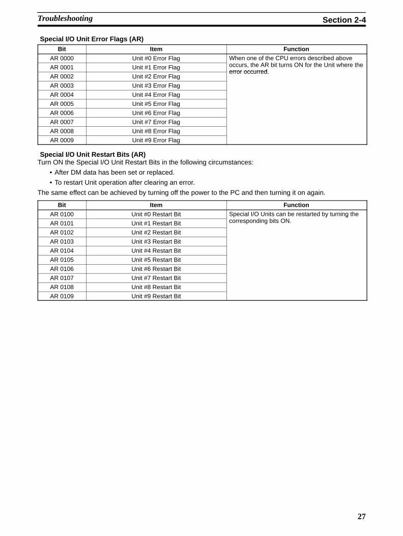
Special I/O Unit Error Flags (AR)Bit Item Function
AR 0000 Unit #0 Error Flag When one of the CPU errors described aboveh AR bi ON f h U i h hAR 0001 Unit #1 Error Flag occurs, the AR bit turns ON for the Unit where the
error occurredAR 0002 Unit #2 Error Flag
error occurred.
AR 0003 Unit #3 Error Flag
AR 0004 Unit #4 Error Flag
AR 0005 Unit #5 Error Flag
AR 0006 Unit #6 Error Flag
AR 0007 Unit #7 Error Flag
AR 0008 Unit #8 Error Flag
AR 0009 Unit #9 Error Flag
Special I/O Unit Restart Bits (AR)Turn ON the Special I/O Unit Restart Bits in the following circumstances:
• After DM data has been set or replaced.
• To restart Unit operation after clearing an error.
The same effect can be achieved by turning off the power to the PC and then turning it on again.
Bit Item Function
AR 0100 Unit #0 Restart Bit Special I/O Units can be restarted by turning thedi bi ONAR 0101 Unit #1 Restart Bit
y gcorresponding bits ON.
AR 0102 Unit #2 Restart Bit
AR 0103 Unit #3 Restart Bit
AR 0104 Unit #4 Restart Bit
AR 0105 Unit #5 Restart Bit
AR 0106 Unit #6 Restart Bit
AR 0107 Unit #7 Restart Bit
AR 0108 Unit #8 Restart Bit
AR 0109 Unit #9 Restart Bit
Troubleshooting Section 2-4

29
SECTION 3C200H-DA001 Analog Output Units
This section provides the information required to install and operate a C200H-DA001 Analog Output Unit.
3-1 Before Operation 30 . . . . . . . . . . . . . . . . . . . . . . . . . . . . . . . . . . . . . . . . . . . . . . . . . . 3-1-1 Nomenclature and Functions 30 . . . . . . . . . . . . . . . . . . . . . . . . . . . . . . . . . 3-1-2 Switch Settings 32 . . . . . . . . . . . . . . . . . . . . . . . . . . . . . . . . . . . . . . . . . . . 3-1-3 Wiring 33 . . . . . . . . . . . . . . . . . . . . . . . . . . . . . . . . . . . . . . . . . . . . . . . . . .
3-2 Bit and DM Allocations 36 . . . . . . . . . . . . . . . . . . . . . . . . . . . . . . . . . . . . . . . . . . . . . 3-3 Functions and Programming 38 . . . . . . . . . . . . . . . . . . . . . . . . . . . . . . . . . . . . . . . . .
3-3-1 Output Signal Range Setting 39 . . . . . . . . . . . . . . . . . . . . . . . . . . . . . . . . . 3-3-2 Output Limits 39 . . . . . . . . . . . . . . . . . . . . . . . . . . . . . . . . . . . . . . . . . . . . 3-3-3 Output Limit Alarms 41 . . . . . . . . . . . . . . . . . . . . . . . . . . . . . . . . . . . . . . . 3-3-4 Pulse Output 42 . . . . . . . . . . . . . . . . . . . . . . . . . . . . . . . . . . . . . . . . . . . . . 3-3-5 Data Setting Example and Programming Concepts 43 . . . . . . . . . . . . . . .
3-4 Troubleshooting 45 . . . . . . . . . . . . . . . . . . . . . . . . . . . . . . . . . . . . . . . . . . . . . . . . . . .

30
3-1 Before Operation
3-1-1 Nomenclature and Functions
Displaypanel
External outputterminal block
connectors
Unit numbersetting switch
Model label
Function setting switch
Backplane connector
Indicators
Indicator Color Function
RUN Green Lit when the Analog Output Unit is operating correctly. If operation is not normal, thisindicator turns OFF and Unit operation is stopped.
ALARM Red Lit when an alarm is output as a result of the upper or lower limits being exceeded,
The following table briefly outlines the basic functions of the C200H-DA001.These functions are covered in more detail in 3-3 Functions and Programming.
Function Explanation
Output range setting The output range can be set according to the output signal level that is to be used. Thesame output range is used for all of the outputs for a particular Unit. The voltage rangeof 1 to 5 V and the current range of 4 to 20 mA, however, can be used at the user’soption at any output.
Output limit The output limit function sets upper and lower limits on the output signal. The upper andlower limits are preset in the DM area. The output remains at the limit level as long asthe output limit function is activated.
Output limit alarm This function activates an alarm if the output signal is outside of the range defined bythe upper and lower limits preset in the DM area, but it does not alter the output level. Itis possible to include a deadband, which delays the resetting of the alarm. The outputlimit alarm turns ON and OFF according to the following conditions.
Pulse output This function creates a 0 V to 5 V pulse output separate from the analog output.
Functions
Before Operation Section 3-1

31
The following diagram shows the basic internal configuration of the AnalogOutput Unit.
Photo-coupler
Photo-coupler
Analogsupplypower
DC/DCconverter
+ 5 V
0 V
Pulse output 1
COM
I/O BUS
Pulseoutputcircuit
Voltage output 1
current output 1M
emor
yM
emor
y
Voltage output 2
current output 2
Pulse output 2
Pho
toco
uple
r
Con
vert
erR
ange
sele
ctor
Con
vert
er
Bus
inte
rfac
e
Alarm 1 upper limit
Alarm 2 upper limit
Alarm 1 lower limit
Alarm 2 lower limit
Pulseoutputcircuit
Pho
toco
uple
r
Block Diagram
Before Operation Section 3-1
32
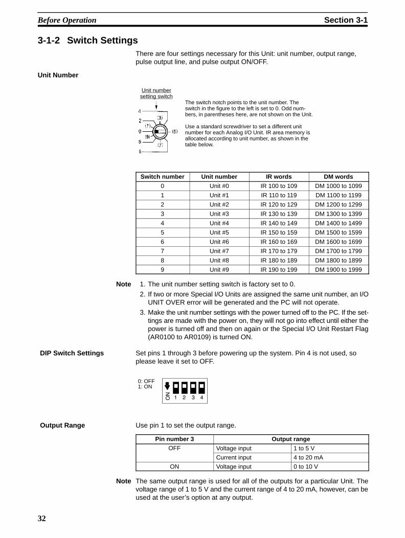
3-1-2 Switch SettingsThere are four settings necessary for this Unit: unit number, output range,pulse output line, and pulse output ON/OFF.
Unit Number
Unit numbersetting switch
The switch notch points to the unit number. Theswitch in the figure to the left is set to 0. Odd num-bers, in parentheses here, are not shown on the Unit.
Use a standard screwdriver to set a different unitnumber for each Analog I/O Unit. IR area memory isallocated according to unit number, as shown in thetable below.
Switch number Unit number IR words DM words
0 Unit #0 IR 100 to 109 DM 1000 to 1099
1 Unit #1 IR 110 to 119 DM 1100 to 1199
2 Unit #2 IR 120 to 129 DM 1200 to 1299
3 Unit #3 IR 130 to 139 DM 1300 to 1399
4 Unit #4 IR 140 to 149 DM 1400 to 1499
5 Unit #5 IR 150 to 159 DM 1500 to 1599
6 Unit #6 IR 160 to 169 DM 1600 to 1699
7 Unit #7 IR 170 to 179 DM 1700 to 1799
8 Unit #8 IR 180 to 189 DM 1800 to 1899
9 Unit #9 IR 190 to 199 DM 1900 to 1999
Note 1. The unit number setting switch is factory set to 0.
2. If two or more Special I/O Units are assigned the same unit number, an I/OUNIT OVER error will be generated and the PC will not operate.
3. Make the unit number settings with the power turned off to the PC. If the set-tings are made with the power on, they will not go into effect until either thepower is turned off and then on again or the Special I/O Unit Restart Flag(AR0100 to AR0109) is turned ON.
Set pins 1 through 3 before powering up the system. Pin 4 is not used, soplease leave it set to OFF.
0: OFF1: ON
Use pin 1 to set the output range.
Pin number 3 Output rangeOFF Voltage input 1 to 5 V
Current input 4 to 20 mA
ON Voltage input 0 to 10 V
Note The same output range is used for all of the outputs for a particular Unit. Thevoltage range of 1 to 5 V and the current range of 4 to 20 mA, however, can beused at the user’s option at any output.
DIP Switch Settings
Output Range
Before Operation Section 3-1
33
Use pin 2 to set the pulse output line.
Pin 2 OFF: Output 1Pin 2 ON: Output 2
Use pin 3 to set pulse outputs to ON or OFF.
Pin 3 OFF: Pulse output OFFPin 3 ON: Pulse output ON
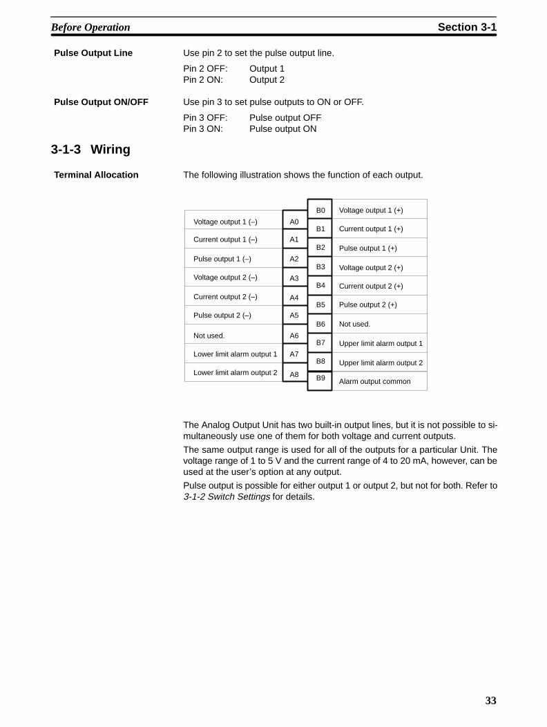
3-1-3 Wiring
The following illustration shows the function of each output.
A0
A2
A4
A6
A8
B0
B2
B4
B6
B9
B1
B3
B5
B7
B8A7
A5
A3
A1
Voltage output 1 (–)
Current output 1 (–)
Pulse output 1 (–)
Not used.
Lower limit alarm output 1
Voltage output 2 (–)
Current output 2 (–)
Pulse output 2 (–)
Lower limit alarm output 2
Voltage output 1 (+)
Current output 1 (+)
Pulse output 1 (+)
Voltage output 2 (+)
Current output 2 (+)
Pulse output 2 (+)
Not used.
Upper limit alarm output 1
Upper limit alarm output 2
Alarm output common
The Analog Output Unit has two built-in output lines, but it is not possible to si-multaneously use one of them for both voltage and current outputs.
The same output range is used for all of the outputs for a particular Unit. Thevoltage range of 1 to 5 V and the current range of 4 to 20 mA, however, can beused at the user’s option at any output.
Pulse output is possible for either output 1 or output 2, but not for both. Refer to3-1-2 Switch Settings for details.
Pulse Output Line
Pulse Output ON/OFF
Terminal Allocation
Before Operation Section 3-1

34
The following diagram shows the external wiring of outputs for theC200H-DA001.
Voltageoutput
1
+
–
Voltageoutput
2
+
–
Currentoutput
1
+
–
Currentoutput
2
+
–
A0Output 1
A1
A2
A3
A4
A5
A7
A8
B0
B1
B2
B3
B4
B5
B7
B8
B9
Pulse output 1
Pulse output 2
0 V
0 V
Output 2
Shield
Load
Load
Load
Load
Load
5 to 24 VDC
100 mA max.
+
– (Note 1.)
C200H-DA001
Note 1. The maximum current capacity for this alarm output (open-collector output)is 100 mA/circuit.
2. A single output line cannot be used for voltage and current output at thesame time.
Output Wiring
Before Operation Section 3-1

!
35
When wiring outputs, apply the following points to avoid noise interference andoptimize Analog Output Unit performance.
• Use shielded twisted-pair cable for external connections and power lines.
• Route output cables separately from the AC cable, and do not run the Unit’scables near a main circuit cable, high voltage cable, or a non-PC load cable.
• Be sure to install surge-absorbing diodes or surge absorbers for inductiveloads (relays, solenoids, electromagnetic valves, etc.) They should beinstalled right next to relays and solenoids. Use surge-absorbing diodes with adielectric strength of at least five times the circuit voltage.
DC Relay
Surge-absorbing diode(Example: ERB44-06,by Fuji Electric)
Solenoid, etc.
AC Relay
Surge absorber
Surge absorber
• If there is noise interference from power lines (if, for example, the power supplyis shared with electrical welding devices or electrical discharge machines, or ifthere is a high-frequency generation source nearby) install a noise filter at thepower supply output area.
• Use at least a class-3 ground (to 100 Ω or less), with as heavy a wire as pos-sible (i.e., at least 1.25 mm2).
Caution When using the C200H-DA001 Analog Output Unit, a voltage (current) may beoutput momentarily from the output terminal when the power supply to the PC isturned ON or OFF.Approximately 10 V will be output for approximately 1 second after the power isturned ON or OFF.If this causes a problem, provide countermeasures so that the power supply oroutput timing of external devices differs from the ON/OFF timing of the powersupply to the PC.
Output WiringConsiderations
Before Operation Section 3-1
36
3-2 Bit and DM Allocations
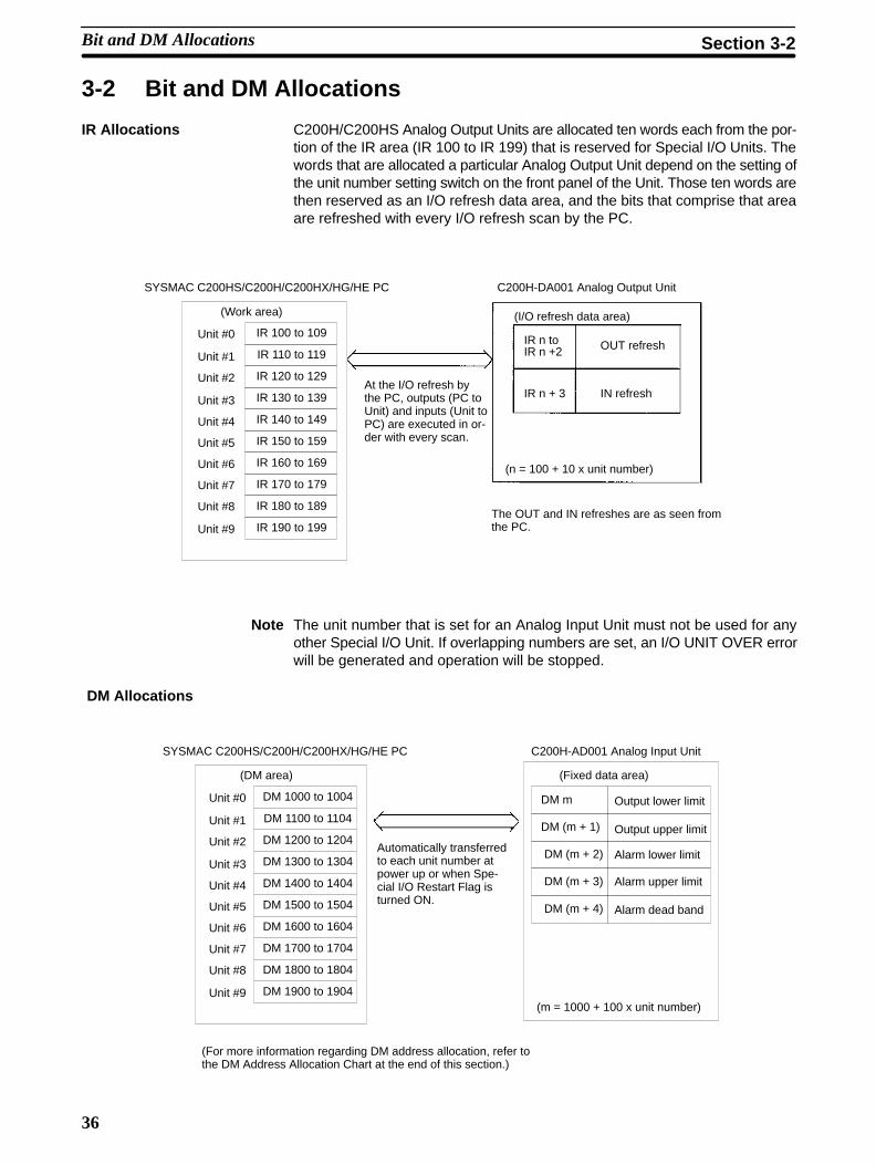
IR Allocations C200H/C200HS Analog Output Units are allocated ten words each from the por-tion of the IR area (IR 100 to IR 199) that is reserved for Special I/O Units. Thewords that are allocated a particular Analog Output Unit depend on the setting ofthe unit number setting switch on the front panel of the Unit. Those ten words arethen reserved as an I/O refresh data area, and the bits that comprise that areaare refreshed with every I/O refresh scan by the PC.
IR n toIR n +2
IR n + 3IR 130 to 139
IR 140 to 149
IR 150 to 159
IR 100 to 109
IR 110 to 119
IR 120 to 129
IR 190 to 199
IR 160 to 169
IR 170 to 179
IR 180 to 189
SYSMAC C200HS/C200H/C200HX/HG/HE PC C200H-DA001 Analog Output Unit
IN refresh
(I/O refresh data area)
(n = 100 + 10 x unit number)
Unit #0
Unit #1
Unit #2
Unit #3
Unit #4
Unit #5
Unit #6
Unit #7
Unit #8
Unit #9
(Work area)
At the I/O refresh bythe PC, outputs (PC toUnit) and inputs (Unit toPC) are executed in or-der with every scan.
The OUT and IN refreshes are as seen fromthe PC.
OUT refresh
Note The unit number that is set for an Analog Input Unit must not be used for anyother Special I/O Unit. If overlapping numbers are set, an I/O UNIT OVER errorwill be generated and operation will be stopped.
DM Allocations
Output lower limitDM m
DM (m + 1)
DM (m + 2)
DM (m + 3)
DM (m + 4)
DM 1900 to 1904
DM 1800 to 1804
DM 1700 to 1704
DM 1600 to 1604
DM 1500 to 1504
DM 1400 to 1404
DM 1300 to 1304
DM 1200 to 1204
DM 1100 to 1104
DM 1000 to 1004Unit #0
SYSMAC C200HS/C200H/C200HX/HG/HE PC C200H-AD001 Analog Input Unit
(Fixed data area)
Automatically transferredto each unit number atpower up or when Spe-cial I/O Restart Flag isturned ON.
Unit #1
Unit #2
Unit #3
Unit #4
Unit #5
Unit #6
Unit #7
Unit #8
Unit #9(m = 1000 + 100 x unit number)
(For more information regarding DM address allocation, refer tothe DM Address Allocation Chart at the end of this section.)
(DM area)
Output upper limit
Alarm lower limit
Alarm upper limit
Alarm dead band
Bit and DM Allocations Section 3-2
37
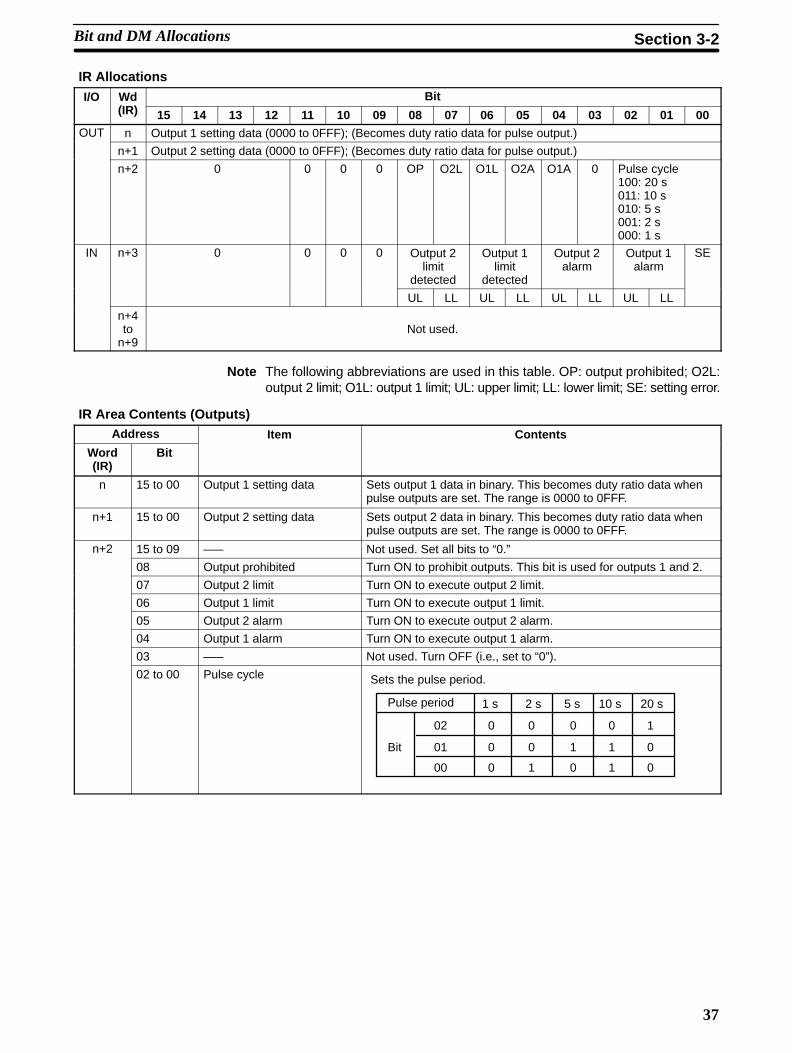
IR Allocations
I/O Wd(IR)
Bit(IR) 15 14 13 12 11 10 09 08 07 06 05 04 03 02 01 00
OUT n Output 1 setting data (0000 to 0FFF); (Becomes duty ratio data for pulse output.)
n+1 Output 2 setting data (0000 to 0FFF); (Becomes duty ratio data for pulse output.)
n+2 0 0 0 0 OP O2L O1L O2A O1A 0 Pulse cycle100: 20 s011: 10 s010: 5 s001: 2 s000: 1 s
IN n+3 0 0 0 0 Output 2limit
detected
Output 1limit
detected
Output 2alarm
Output 1alarm
SE
UL LL UL LL UL LL UL LL
n+4to
n+9Not used.
Note The following abbreviations are used in this table. OP: output prohibited; O2L:output 2 limit; O1L: output 1 limit; UL: upper limit; LL: lower limit; SE: setting error.
IR Area Contents (Outputs)Address Item Contents
Word(IR)
Bit
n 15 to 00 Output 1 setting data Sets output 1 data in binary. This becomes duty ratio data whenpulse outputs are set. The range is 0000 to 0FFF.
n+1 15 to 00 Output 2 setting data Sets output 2 data in binary. This becomes duty ratio data whenpulse outputs are set. The range is 0000 to 0FFF.
n+2 15 to 09 ––– Not used. Set all bits to “0.”
08 Output prohibited Turn ON to prohibit outputs. This bit is used for outputs 1 and 2.
07 Output 2 limit Turn ON to execute output 2 limit.
06 Output 1 limit Turn ON to execute output 1 limit.
05 Output 2 alarm Turn ON to execute output 2 alarm.
04 Output 1 alarm Turn ON to execute output 1 alarm.
03 ––– Not used. Turn OFF (i.e., set to “0”).
02 to 00 Pulse cycle Sets the pulse period.
Pulse period
Bit
02
01
00
0
0
0
0
0
1
0
1
0
0
1
1
1
0
0
1 s 10 s 20 s2 s 5 s
Bit and DM Allocations Section 3-2

38
IR Area Contents (Inputs)Word(IR)
Bit Item Contents
n+3 15 to 09 ––– Not used.
08 Output 2 limitd d
Upper limit: Turns ON when output 2 value is greater than the upper limit.
07 detected Lower limit: Turns ON when output 2 value is less than the lower limit.
06 Output 1 limitd d
Upper limit: Turns ON when output 1 value is greater than the upper limit.
05 detected Lower limit: Turns ON when output 1 value is less than the lower limit.
04 Output 2 alarm(S )
Upper limit: Turns ON when output 2 value is greater than the alarm upper limit.
03 (See note.) Lower limit: Turns ON when output 2 value is less than the alarm lower limit.
02 Output 1 alarm(S )
Upper limit: Turns ON when output 1 value is greater than the alarm upper limit.
01 (See note.) Lower limit: Turns ON when output 1 value is less than the alarm lower limit.
00 Setting error This bit turns ON if the data set in the DM area is wrong. (See note 2.)
Note When alarm flags turn ON, their status can be read from external connection ter-minals A7, A8, B7, and B8. (Refer to 3-1-3 Wiring.) At that time the ALARM indi-cator on the display panel of the Unit will light.
DM AllocationsWord Bit
15 14 13 12 11 10 09 08 07 06 05 04 03 02 01 00
DM m Output lower limit (0000 to 0FFF)
DM (m+1) Output upper limit (0000 to 0FFF)
DM (m+2) Alarm lower limit (0000 to 0FFF)
DM (m+3) Alarm upper limit (0000 to 0FFF)
DM (m+4) Alarm dead band (0000 to 0FFF)
Note 1. The DM area that is used is a read-only area, so the data cannot be writtenfrom the program. Use the Programming Console to set data by changingthe present value or changing three words together.
2. Data that is set in the DM area is transferred either at the time of power up orwhen the Special I/O Unit Restart Bit is turned ON. Any data that is set in themeantime will remain invalid until then.
3. The values set in DM are used for both output lines (i.e., for output 1 andoutput 2).
4. m = 1000 + 100 x unit number.
3-3 Functions and ProgrammingThe C200H-DA001 Analog Output Unit provides 4 functions
• Output signal range setting
• Output limit
• Output limit alarm
• Pulse output
These functions are set using Unit switches and Peripheral Devices, such as aProgramming Console. The words allocated to the Unit in the DM Area (DM m toDM m+4) cannot be written from user program and all data set in these wordsmust be written from a Peripheral Device.
When inputting data from a Programming Console, use the operations tochange present values. When inputting from the SSS (SYSMAC Support Soft-ware), use the DM editing operations.
The data set in the DM area is transferred to the Analog Output Unit when eitherof the following steps is taken. Be sure to perform one or the other of these stepswhenever new data has been set or data has been changed.
Functions and Programming Section 3-3

39
• Turning ON the power to the C200H/C200HS CPU.
• Turning ON the Restart Bit allocated to the Unit as a Special I/O Unit (AR 0100to 0109).
3-3-1 Output Signal Range Setting
The C200H-DA001 converts 12-bit binary data (3-digit hexadecimal) from thePC to analog output in one of three ranges: 0 to 10 V, 1 to 5 V, or 4 to 20 mA.
The C200H-DA001 can convert analog output signals in three ranges: 0 to 10 V, 1 to 5 V, or 4 to 20 mA. The range is set on pin 1 of the DIP switchas shown below.
Pin 1 Input range
OFF 1 to 5 V
4 to 20 mA
ON 0 to 10 V
If the 0 to 10 V setting is used, it must be used for all two outputs. The 1 to5 V and 4 to 20 mA ranges can be used at the same time for different out-puts.
Digital Output vs. Analog Input
10 V
00 V
0
1 V (4 mA)
Output
Digitalvalue
0 V to 10 V Output(pin 1 ON)
1 V to 5 V and 4 mA to 20 mA Outputs(pin 1 OFF)
5 V (20 mA)
Digitalvalue
Output
0FFF(4095)
0FFF(4095)
3-3-2 Output Limits
The output limit function can be used to establish upper and lower limits for theoutput signal. The limits can be used to restrict the output for any of a number ofpossible reasons, e.g., to prevent unsuitable outputs from occurring even whenincorrect data is set.
This function can be used at the same time as the output limit alarm function.
The upper and lower limits are preset as binary values in the DM area (lower limitin DM m and upper limit in DM m+1). The output will remain between the upperand lower limits as long as the output limit function is activated.
Functions and Programming Section 3-3

40
If the output goes beyond either limit, an Output Limit Flag (bits 05 to 08 in IRn+3) will turn ON and the output will remain at the limit value
Lower LimitFlag ON
Output level
Output limit upper level
Output limit lower level
Output remains atupper or lower limit
Time
Upper LimitFlag ON
Use the following procedure to set upper and lower limits.
1, 2, 3... 1. Set the lower and upper limits in DM m and DM m+1. The setting range isbetween 0000 and 0FFF (binary data). Set the limits from the ProgrammingConsole. This data cannot be changed from the user’s program.
Note Calculations of the desired limit can be made as shown in the follow-ing example. To set an upper limit of 8 V for a 0 to 10 V range setting,use the following equation and set the results (0CCC) in DM m+1:8/10 x 0FFF = 0CCC
2. Turn power to the PC off then then back on or turn ON the Special I/O UnitRestart Bit allocated to the Unit (AR 0100 to AR 0109).
3. Turn ON the Output Limit ON Bit for the desired output:Output 1 Limit ON Bit: Bit 06 of IR n+2Output 2 Limit ON Bit: Bit 07 of IR n+2
Functions and Programming Section 3-3

41
3-3-3 Output Limit AlarmsThis function activates an alarm if the output signal is outside of the range de-fined by the upper and lower limits preset in the DM area, but it does not alter theoutput level. It is possible to include a deadband, which delays the resetting ofthe alarm.
ON
OFF
ON
OFF
Output limit alarm upper limit
Output limit alarm lower limit
Output Upper Limit Alarm Flag
Output Lower Limit Alarm Flag
Dead-band
Dead-band
Time
Output level
This function can be used at the same time as the output limit function.
The output limit alarms turn ON and OFF according to the following conditions.
Upper limit:ON: analog output ≥ output limit alarm upper limitOFF: analog output < output limit alarm upper limit – deadband width
Lower limit:ON: analog output ≤ output limit alarm lower limitOFF: analog output > output limit alarm lower limit + deadband width
When any of the Output Limit Alarm Flags turn ON, the ALARM indicator onthe Unit will light and signals will be generated on external terminals A7, A8,B7, and B8 (refer to 3-1-3 Wiring for details).
Use the following procedure to set upper and lower limit alarms.
1, 2, 3... 1. Set the lower and upper alarm limits in DM m+2 to DM m+4. The settingrange is between 0000 and 0FFF (binary data). Set the limits from the Pro-gramming Console. This data cannot be changed from the user’s program.
Note Calculations of the desired limit can be made as shown in the follow-ing example. To set an upper limit alarm at 4.75 V for a 1 to 5 V rangesetting, use the following equation and set the results (0F00) inDM m+1:(4.75 – 1)/(5 – 1) x 0FFF = 15/16 x 0FFF = 0F00
2. Turn power to the PC off then then back on or turn ON the Special I/O UnitRestart Bit allocated to the Unit (AR 0100 to AR 0109).
3. Turn ON the Output Alarm ON Bit for the desired output:Output 1 Alarm ON Bit: Bit 04 of IR n+2Output 2 Alarm ON Bit: Bit 05 of IR n+2
Functions and Programming Section 3-3

42
3-3-4 Pulse Output
The pulse output function can be used to create a 0 to 5 V pulse output for eitheroutput 1 or 2 in addition to the analog output.
The pulse period and duty ratio (ON/OFF ratio) can be set for the pulse output.These settings can be made from the user program.
5 V
0 VON OFF
Amplitude
Pulseperiod
Duty ratio = ON time/pulse period
Note The resolution of the duty ratio is 1/256.
Use the following procedure to set a pulse output.
1, 2, 3... 1. Turn ON pin 3 of the DIP switch on the back of the Unit to select pulse output.
2. Turn OFF pin 2 to select output 1, or ON to select output 2. Both outputs can-not be pulse at the same time.
3. Set the pulse period in bits 00 to 02 of IR n+2 as shown below.
Bis in IR n Period
00 01 02
0 0 0 1 s
1 0 0 2 s
0 1 0 5 s
1 1 0 10 s
0 0 1 20 s
4. Set the duty ratio (ON/OFF ratio) for the pulse output in IR n. Refer to 3-3-5Data Setting Example and Programming Concepts for setting methods.
Calculating Settings To set a duty ratio of 80% , set the results of the following calculation (0CCC) inIR n: 80/100 x 0FFF = 0CCC.
If either the duty ratio or period is changed during operation, the output will notchange until 1 full period has been completed.
Data changed Pulse output calculation notchanged until this point
Functions and Programming Section 3-3

43
3-3-5 Data Setting Example and Programming Concepts
Data SettingsThe following settings are used in this example. Data in the DM area is set usingthe SSS, a Programming Console, or another Peripheral Device. Turn power tothe PC off then then back on or turn ON the Special I/O Unit Restart Bit allocatedto the Unit (AR 0100 to AR 0109) after setting the data so that the data is read intothe Analog Output Unit.
Item Setting
Unit number 0 (allocated words: IR 100 to IR 109 and DM 1000 to DM 1004)
Item Output 1 Output 2
DM word for storing output data DM 0000 DM 0001
Lower limit output bit IR 00100 –––
Upper limit output bit IR 00101 –––
Lower limit alarm output terminal ––– A8
Upper limit alarm output terminal ––– B8
Details
Item Output 1 Output 2
Output signal range 1 to 5 V 4 to 20 mA
Output limit function ON OFF
Limit alarm function OFF ON
Item Actual value Setting
Output limits Lower limit 1.25 V 0100
Upper limit 4.75 V 0F00
Alarm limits Lower limit 6 mA 0200
Upper limit 19 mA 0F00
Deadband 0.5 mA 0080
DM Area Settings
DM word Data Setting
DM 1000 0100 Output limit lower limit
DM 1001 0F00 Output limit upper limit
DM 1002 0200 Alarm lower limit
DM 1003 0F00 Alarm upper limit
DM 1004 0080 Deadband for alarm
ProgrammingThe types of programming required to use an Analog Output Unit are describedin this section. Refer to the operation manual for the C200H/C200HS for detailson programming.
Functions and Programming Section 3-3
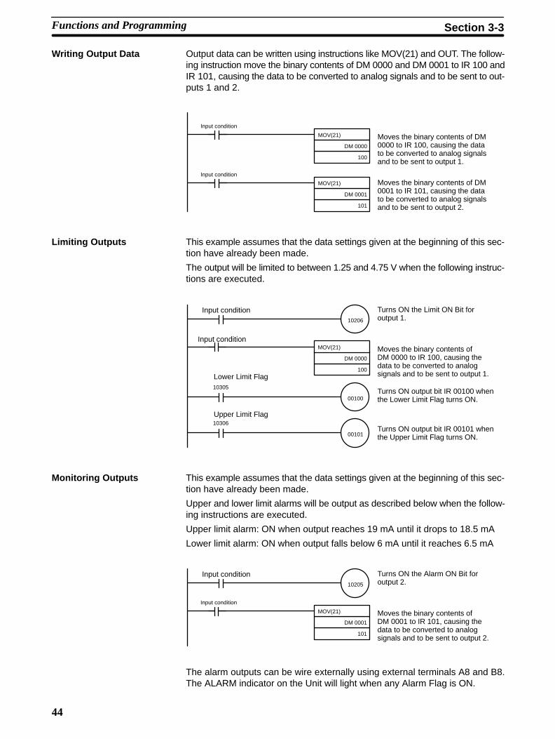
44
Writing Output Data Output data can be written using instructions like MOV(21) and OUT. The follow-ing instruction move the binary contents of DM 0000 and DM 0001 to IR 100 andIR 101, causing the data to be converted to analog signals and to be sent to out-puts 1 and 2.
MOV(21)
DM 0000
100
Input condition
MOV(21)
DM 0001
101
Input condition
Moves the binary contents of DM0000 to IR 100, causing the datato be converted to analog signalsand to be sent to output 1.
Moves the binary contents of DM0001 to IR 101, causing the datato be converted to analog signalsand to be sent to output 2.
Limiting Outputs This example assumes that the data settings given at the beginning of this sec-tion have already been made.
The output will be limited to between 1.25 and 4.75 V when the following instruc-tions are executed.
MOV(21)
DM 0000
100
Input conditionMoves the binary contents ofDM 0000 to IR 100, causing thedata to be converted to analogsignals and to be sent to output 1.
10206
Input condition
00100
10305
00101
10306
Turns ON the Limit ON Bit foroutput 1.
Turns ON output bit IR 00100 whenthe Lower Limit Flag turns ON.
Turns ON output bit IR 00101 whenthe Upper Limit Flag turns ON.
Lower Limit Flag
Upper Limit Flag
Monitoring Outputs This example assumes that the data settings given at the beginning of this sec-tion have already been made.
Upper and lower limit alarms will be output as described below when the follow-ing instructions are executed.
Upper limit alarm: ON when output reaches 19 mA until it drops to 18.5 mA
Lower limit alarm: ON when output falls below 6 mA until it reaches 6.5 mA
MOV(21)
DM 0001
101
Input condition
Moves the binary contents ofDM 0001 to IR 101, causing thedata to be converted to analogsignals and to be sent to output 2.
10205
Input condition Turns ON the Alarm ON Bit foroutput 2.
The alarm outputs can be wire externally using external terminals A8 and B8.The ALARM indicator on the Unit will light when any Alarm Flag is ON.
Functions and Programming Section 3-3

45
Pulse Output This example shows how to set pulse outputs on output 1. The pulse output set-tings are given in the following table.
Item Value Data settingPulse output Duty 80% 0CCC in IR 100
Pulse period 2 s Turn ON IR 10200
1.6 s
2 s
Duty = 80% (0CCC)Pulse period = 2 s (IR 10200 turned ON)
0.4 s
5 V
0 V
Turn OFF pin 2 (specifying output 1) and turn ON pin 3 (enabling pulse output) onthe back-panel DIP switch before starting.
Execute the following instructions in the program. Pulse outputs will be made onoutput 1.
MOV(21)
#0CCC
100
Input condition
Sets the duty ratio to 80%.
Sets the period at 2 seconds.10200
3-4 TroubleshootingWhen an error occurs, the contents are output to the SR and HR areas. The fol-lowing tables show the various errors that may occur, along with their probablecauses and remedies.
Unit error Probable causes and operations Possible remedies
Setting error The data set in the DM area is wrong. In this case,the Setting Error Flag (IR n+3, bit 00) will be ON.
Check the contents of the data.
RUN indicator not lit The RUN indicator on the Unit is not lit even thoughpower is turned on to the PC, and none of the errorsdescribed in this table are applicable.
Replace the Unit.
CPU error Probable causes and operations Possible remedies
CPU waiting • The Special I/O Unit is defective.
• The PC will not run.
• Replace the Special I/O Unit.
• The defective Unit should appear as $signs only in the I/O table read opera-tion.
Duplicated unit number The same number is assigned to more than oneSpecial I/O Unit. In this case the PC will not run andSR25415 will turn ON.
Do not assign the same number to morethan one Unit. Use the I/O table readoperation to display unit numbers.
Special I/O Unit error An error has occurred in the refresh signal betweenthe CPU and the Special I/O Unit. In this case, onlythe Special I/O Unit stops. SR 25415 is turned ON.
Check AR 0000 to AR 0009 for the unitnumber of the Unit in error. Aftercorrecting the error, turn ON the properbit in AR 0100 to AR 0109. If the errordoes not clear after initialization, replacethe Unit.
Detection When ErrorsOccur
Troubleshooting Section 3-4

46
Special I/O Unit Error Detection Bit (SR)Bit Error Explanation Operation status
25415 Duplicated unit number One number is assigned to morethan one Special I/O Unit.
PC operation stops.
Special I/O Unit error An error has occurred in the refreshsignal between the CPU and theSpecial I/O Unit
Operation stops only for the faultyUnit.
Special I/O Unit Error Flags (AR)Bit Item Function
AR 0000 Unit #0 Error Flag When one of the CPU errors described aboveh AR bi ON f h U i h hAR 0001 Unit #1 Error Flag occurs, the AR bit turns ON for the Unit where the
error occurredAR 0002 Unit #2 Error Flag
error occurred.
AR 0003 Unit #3 Error Flag
AR 0004 Unit #4 Error Flag
AR 0005 Unit #5 Error Flag
AR 0006 Unit #6 Error Flag
AR 0007 Unit #7 Error Flag
AR 0008 Unit #8 Error Flag
AR 0009 Unit #9 Error Flag
Special I/O Unit Restart Bits (AR)Turn ON the Special I/O Unit Restart Bits in the following circumstances:
• After DM data has been set or replaced.
• To restart Unit operation after clearing an error.
The same effect can be achieved by turning off the power to the PC and then turning it on again.
Bit Item Function
AR 0100 Unit #0 Restart Bit Special I/O Units can be restarted by turning thedi bi ONAR 0101 Unit #1 Restart Bit
y gcorresponding bits ON.
AR 0102 Unit #2 Restart Bit
AR 0103 Unit #3 Restart Bit
AR 0104 Unit #4 Restart Bit
AR 0105 Unit #5 Restart Bit
AR 0106 Unit #6 Restart Bit
AR 0107 Unit #7 Restart Bit
AR 0108 Unit #8 Restart Bit
AR 0109 Unit #9 Restart Bit
Troubleshooting Section 3-4
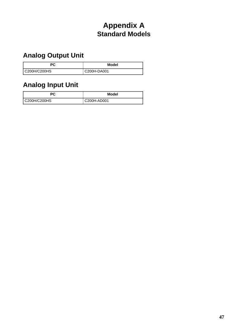
47
Appendix AStandard Models
Analog Output UnitPC Model
C200H/C200HS C200H-DA001
Analog Input UnitPC Model
C200H/C200HS C200H-AD001

49
Appendix BSpecifications
C200H-AD001 Analog Input Unit
General SpecificationsAll general specifications of the C200H-AD001 Analog Input Unit conform to those of the C Series.
Performance SpecificationsItem Specifications
Number of analog inputs 4 max.
Input signal range (note 1) Voltage input 1 to 5 V
0 to 10 V
Current input 4 to 20 mA
Max. input signal (note 2) Voltage input 15 V
Current input 30 mA
Input impedance Voltage input 1 MΩ min.
Current input 250 Ω (rated value)
Resolution 1/4000 max. (full scale)
Converted data 12-bit binary (0000 to 0FA0)
Accuracy (note 3) 25°C 0.5% (full scale, including linearity error)
0° to 55°C 1.0% (full scale, including linearity error)
Conversion time (note 4) 2.5 ms max./point
Isolation Between input terminals and PC: photocoupler
Between input terminals: none
External connections 19-pin terminal block (removable)
Power consumption 550 mA max. at 5 VDC
Dimensions 34.5 x 130 x 128 (W x H x D) mm (see last page of this appendix)
Weight 450 g max.
Note 1. All points on the same Unit must use the same input range except for the 1 to 5-V and 4 to 20-mA ranges,which can be specified by point.
2. Operation in ranges beyond the maximum input signals will damage the Unit. Operate within the rangeslisted above.
3. The accuracy is given for full scale (4,000). For example, an accuracy of 5% means a maximum errorof 20 (BCD).
4. This is the time it takes for a full range input signal to be converted and to be stored in the memory of theUnit. It takes at least one scan before the converted data is read by the CPU.

Appendix BSpecifications
50
Input Specifications
0 V 1 V(4 mA)
5 V(20 mA)
10 V
0 to 10 V1 to 5 v/4 to 20 mA
Converted output data(Top: BinaryParentheses: BCD)
Input signal
Note 1. All points on the same Unit must use the same input range except for the 1 to 5-V and 4 to 20-mA ranges,which can be specified by point. Refer to 2-1-2 Switch Settings for setting methods.
2. The maximum or minimum output value will be maintained if the input signals goes beyond the maxi-mum (10 V, 5V, or 20 mA) or minimum (0 V, 1V, or 4 mA).

Appendix BSpecifications
51
C200H-DA001 Analog Output UnitAll general specifications of the C200H-DA001 Analog Output Unit conform to those of the C Series.
Item Specifications
Number of analog outputs 2
Output signal range (note 1) Voltage outputs 1 to 5 V
0 to 10 V
Current outputs 4 to 20 mA
Max. output impedance Voltage output: 0.5 Ω
Max. output current Voltage output: 15 mA
Max. load resistance Current output: 400 Ω
Resolution 1/4095 max. (full scale)
Set data 12-bit binary (0000 to 0FFF)
Accuracy (note 2) 25°C ±0.5% max. (full scale, including linearity error)
0° to 55°C ±1.0% max. (full scale, including linearity error)
Conversion time (note 3) 2.5 ms max./point
Isolation Between output terminals and PC: photocoupler
Between output terminals: none
External connections 19-pin terminal block (removable)
Power consumption 650 mA max. at 5 VDC
Dimensions 34.5 x 130 x 128 (W x H x D) mm (see last page of this appendix)
Weight 450 g max.
Note 1. All points on the same Unit must use the same output range except for the 1 to 5-V and 4 to 20-mAranges, which can be specified by point.
2. The accuracy is given for full scale (4,095). For example, an accuracy of ±5% means a maximum error of20 (BCD).
3. This is the time from after the data has been written to the Unit until an analog output appears. The outputdata will not be correct if output data is rewritten faster than it can be output.

Appendix BSpecifications
52
Output Specifications
Digital input data(Top: BinaryParentheses: BCD)
Output signal
1 V(4 mA)
5 V(20 mA)
10 V
0 V
0 to 10 V1 to 5 V/4 to 20 mA
Note All points on the same Unit must use the same output range except for the 1 to 5-V and 4 to 20-mA ranges,which can be specified by point. Refer to 3-1-2 Switch Settings for setting methods.
Dimensions (Unit: mm)The dimensions are the same for both the C200H-AD001 and C200H-DA001.
Bac
kpla
ne
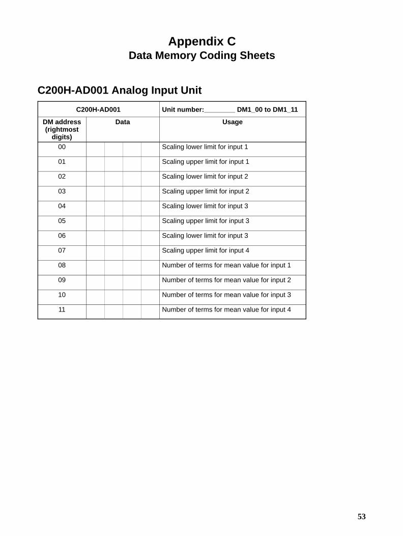
53
Appendix CData Memory Coding Sheets
C200H-AD001 Analog Input Unit
C200H-AD001 Unit number: DM1_00 to DM1_11
DM address(rightmost
digits)
Data Usage
00 Scaling lower limit for input 1
01 Scaling upper limit for input 1
02 Scaling lower limit for input 2
03 Scaling upper limit for input 2
04 Scaling lower limit for input 3
05 Scaling upper limit for input 3
06 Scaling lower limit for input 3
07 Scaling upper limit for input 4
08 Number of terms for mean value for input 1
09 Number of terms for mean value for input 2
10 Number of terms for mean value for input 3
11 Number of terms for mean value for input 4

Appendix CData Memory Coding Sheets
54
C200H-DA001 Analog Output Unit
C200H-DA001 Unit number: DM1_00 to DM1_04
DM address(rightmost
digits)
Data Usage
00 Lower output limit
01 Upper output limit
02 Lower alarm limit
03 Upper alarm limit
04 Alarm deadband

55
Index
AA/D conversion data, 16 analog input vs. digital output, 19
Bblock diagramC200HAD001, 9 C200HDA001, 31
Cconfigurations, system, 4 considerations, 5
Ddata memory coding sheet, 53 data reading mode, setting, 11 digital output vs. analog input, 39 dimensions, 52 disconnection detection, 23 DM area allocationC200HAD001, 15 , 17 C200HDA001, 36 , 38
DM area contents, C200HAD001, 18
Ffield devices, 3
IindicatorsC200HAD001, 8 C200HDA001, 30
input disconnection detection function, 23 input signal range, setting, 11 , 19 inputsnumber, setting, 10 signal range, setting, 11 , 19
IR area allocationC200HAD001, 15 , 16 C200HDA001, 36 , 37
IR area contentsC200HAD001, 16 C200HDA001, 37
Mmean function, 21 models, 47
Nnumber of inputs, setting, 10
Ooutput limit alarm function, 41 output limit function, 39 output signal range, setting, 32 , 39 outputs, signal range, setting, 32 , 39
Ppeak value function, 22 precautions, xi , 2 , 5 applications, xiii general, xii operating environment, xiii safety, xii
programming examplesC200HAD001, 24 C200HDA001, 43
pulse output function, 42 pulse output line, setting, 33 pulse outputs, setting, 33
Sscaling function, 20 Slave Racks, 5 specifications, 49 square root function, 19 switchesC200HAD001, 10 C200HDA001, 32
TtroubleshootingC200HAD001, 26 C200HDA001, 45
Uunit number, setting, Analog Input Unit, 10 unit numbers, settingC200HAD001, 10 C200HDA001, 32
Units, number, 5
WwiringC200HAD001, 11 C200HDA001, 33


![SITE PLAN 1 : 1000 @ A1 G 20170013 AD-DA001 · [Project] [Client] Level One, One Chifley Square Sydney NSW 2000 Australia +61 2 9957 3988 [Ref] [Nom. Architect] [File] [Print Date]](https://static.fdocuments.in/doc/165x107/5f7a12f1a6c54d366c768a09/site-plan-1-1000-a1-g-20170013-ad-da001-project-client-level-one-one-chifley.jpg)