SYSDRIVE 3G3XV Inverter 3G3XV- -EV2 - manuali.eltex.biz · 1 SECTION 1 SYSDRIVE 3G3XV Inverter Main...
81
SYSDRIVE 3G3XV Inverter 3G3XV-:::::-EV2 Operation Manual Revised November 1997
Transcript of SYSDRIVE 3G3XV Inverter 3G3XV- -EV2 - manuali.eltex.biz · 1 SECTION 1 SYSDRIVE 3G3XV Inverter Main...

SYSDRIVE 3G3XV Inverter3G3XV--EV2
Operation Manual
Revised November 1997

iv

!
!
!
v
Notice:OMRON products are manufactured for use according to proper procedures by a qualified operatorand only for the purposes described in this manual.
The following conventions are used to indicate and classify precautions in this manual. Always heedthe information provided with them. Failure to heed precautions can result in injury to people or dam-age to the product.
DANGER Indicates information that, if not heeded, is likely to result in loss of life or seriousinjury.
WARNING Indicates information that, if not heeded, could possibly result in loss of life orserious injury.
Caution Indicates information that, if not heeded, could result in relatively serious orminor injury, damage to the product, or faulty operation.
OMRON Product ReferencesAll OMRON products are capitalized in this manual. The word “Unit” is also capitalized when it refersto an OMRON product, regardless of whether or not it appears in the proper name of the product.
The abbreviation “Ch,” which appears in some displays and on some OMRON products, often means“word” and is abbreviated “Wd” in documentation in this sense.
The abbreviation “PC” means Programmable Controller and is not used as an abbreviation for any-thing else.
Visual AidsThe following headings appear in the left column of the manual to help you locate different types ofinformation.
Note Indicates information of particular interest for efficient and convenient operationof the product.
1, 2, 3... 1. Indicates lists of one sort or another, such as procedures, checklists, etc.
OMRON, 1993All rights reserved. No part of this publication may be reproduced, stored in a retrieval system, or transmitted, in anyform, or by any means, mechanical, electronic, photocopying, recording, or otherwise, without the prior written permis-sion of OMRON.
No patent liability is assumed with respect to the use of the information contained herein. Moreover, because OMRON isconstantly striving to improve its high-quality products, the information contained in this manual is subject to changewithout notice. Every precaution has been taken in the preparation of this manual. Nevertheless, OMRON assumes noresponsibility for errors or omissions. Neither is any liability assumed for damages resulting from the use of the informa-tion contained in this publication.

vi

TABLE OF CONTENTS
vii
SECTION 1SYSDRIVE 3G3XV Inverter Main Unit 1. . . . . . . .
1-1 Part Names of the 3G3XV 2. . . . . . . . . . . . . . . . . . . . . . . . . . . . . . . . . . . . . 1-2 Receiving 2. . . . . . . . . . . . . . . . . . . . . . . . . . . . . . . . . . . . . . . . . . . . . . . . . . 1-3 Installation 3. . . . . . . . . . . . . . . . . . . . . . . . . . . . . . . . . . . . . . . . . . . . . . . . . 1-4 Wiring 5. . . . . . . . . . . . . . . . . . . . . . . . . . . . . . . . . . . . . . . . . . . . . . . . . . . . 1-5 Operation 16. . . . . . . . . . . . . . . . . . . . . . . . . . . . . . . . . . . . . . . . . . . . . . . . . . 1-6 Specifications 21. . . . . . . . . . . . . . . . . . . . . . . . . . . . . . . . . . . . . . . . . . . . . . .
SECTION 2Digital Operator 27. . . . . . . . . . . . . . . . . . . . . . . . . . . .
2-1 Digital Operator Components 28. . . . . . . . . . . . . . . . . . . . . . . . . . . . . . . . . . 2-2 Function/Constant Setting 29. . . . . . . . . . . . . . . . . . . . . . . . . . . . . . . . . . . . . 2-3 Digital Operator Operation Example 31. . . . . . . . . . . . . . . . . . . . . . . . . . . . . 2-4 Constant Initialization and Write-protection 33. . . . . . . . . . . . . . . . . . . . . . . 2-5 Corrective Function 34. . . . . . . . . . . . . . . . . . . . . . . . . . . . . . . . . . . . . . . . . . 2-6 Monitor 35. . . . . . . . . . . . . . . . . . . . . . . . . . . . . . . . . . . . . . . . . . . . . . . . . . . 2-7 Function/Constant List 37. . . . . . . . . . . . . . . . . . . . . . . . . . . . . . . . . . . . . . . . 2-8 Description of Functions and Constants 43. . . . . . . . . . . . . . . . . . . . . . . . . .
SECTION 3Troubleshooting and Maintenance 65. . . . . . . . . . . . .
3-1 Fault Display 66. . . . . . . . . . . . . . . . . . . . . . . . . . . . . . . . . . . . . . . . . . . . . . . 3-2 Correcting Motor Faults 69. . . . . . . . . . . . . . . . . . . . . . . . . . . . . . . . . . . . . . . 3-3 Maintenance 70. . . . . . . . . . . . . . . . . . . . . . . . . . . . . . . . . . . . . . . . . . . . . . . .
Revision History 73. . . . . . . . . . . . . . . . . . . . . . . . . . . .
ix
About this Manual:
This manual provides operating procedures and parameter specifications for the SYS-DRIVE 3G3XV All-Digital Low-Noise Inverter.
Section 1 describes handling, wiring, operation, and specifications of the SYSDRIVE3G3XV series (hereinafter called 3G3XV).
Section 2 outlines the digital operator performance,constants, operation, etc.
Section 3 describes maintenance, periodic inspections, troubleshooting, etc.
Before using the 3G3XV, a thorough understanding of this manual is recommended.
This manual will be of great help for daily maintenance, inspection and troubleshooting.
WARNING Failure to read and understand the information provided in this manualmay result in personal injury or death, damage to the product, or productfailure. Please read each section in its entirety and be sure youunderstand the information provided in the section and related sectionsbefore attempting any of the procedures or operations given.
!
1
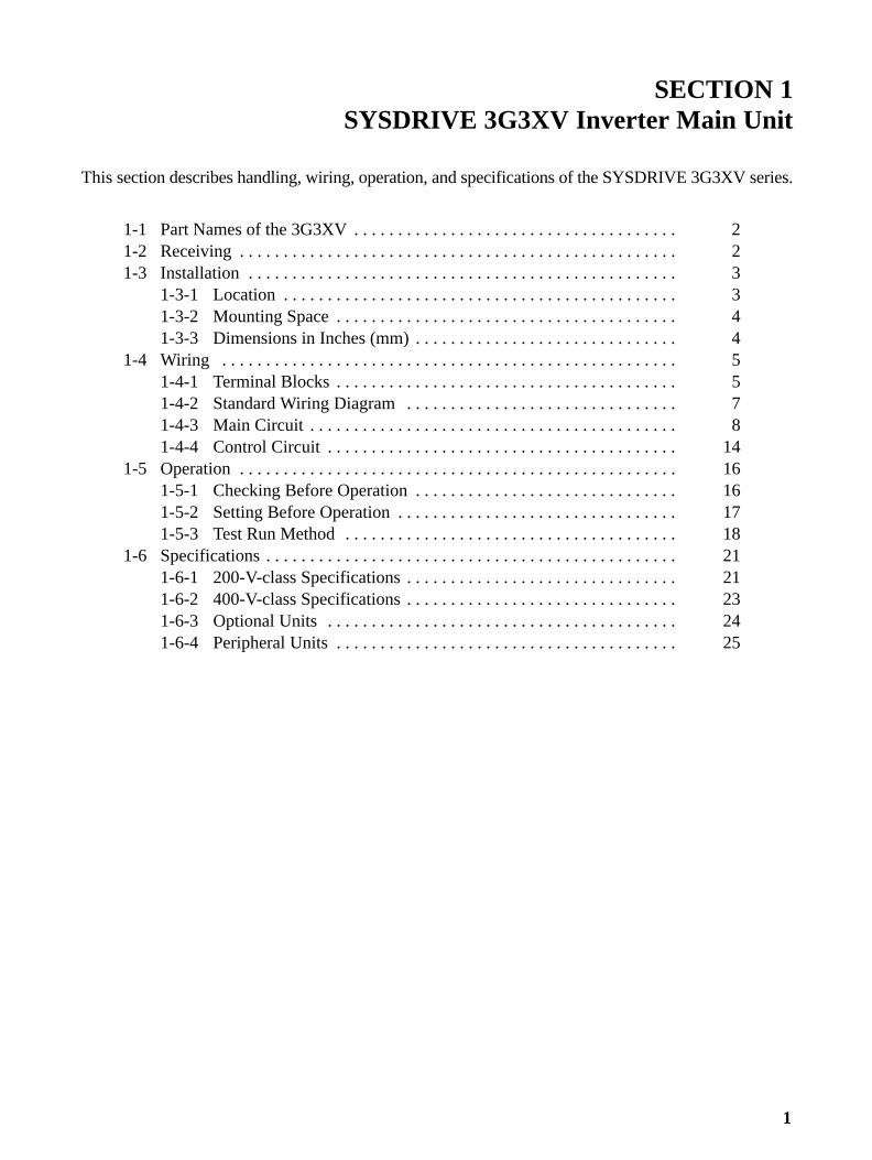
SECTION 1SYSDRIVE 3G3XV Inverter Main Unit
This section describes handling, wiring, operation, and specifications of the SYSDRIVE 3G3XV series.
1-1 Part Names of the 3G3XV 2. . . . . . . . . . . . . . . . . . . . . . . . . . . . . . . . . . . . . 1-2 Receiving 2. . . . . . . . . . . . . . . . . . . . . . . . . . . . . . . . . . . . . . . . . . . . . . . . . . 1-3 Installation 3. . . . . . . . . . . . . . . . . . . . . . . . . . . . . . . . . . . . . . . . . . . . . . . . .
1-3-1 Location 3. . . . . . . . . . . . . . . . . . . . . . . . . . . . . . . . . . . . . . . . . . . . . 1-3-2 Mounting Space 4. . . . . . . . . . . . . . . . . . . . . . . . . . . . . . . . . . . . . . . 1-3-3 Dimensions in Inches (mm) 4. . . . . . . . . . . . . . . . . . . . . . . . . . . . . .
1-4 Wiring 5. . . . . . . . . . . . . . . . . . . . . . . . . . . . . . . . . . . . . . . . . . . . . . . . . . . . 1-4-1 Terminal Blocks 5. . . . . . . . . . . . . . . . . . . . . . . . . . . . . . . . . . . . . . . 1-4-2 Standard Wiring Diagram 7. . . . . . . . . . . . . . . . . . . . . . . . . . . . . . . 1-4-3 Main Circuit 8. . . . . . . . . . . . . . . . . . . . . . . . . . . . . . . . . . . . . . . . . . 1-4-4 Control Circuit 14. . . . . . . . . . . . . . . . . . . . . . . . . . . . . . . . . . . . . . . .
1-5 Operation 16. . . . . . . . . . . . . . . . . . . . . . . . . . . . . . . . . . . . . . . . . . . . . . . . . . 1-5-1 Checking Before Operation 16. . . . . . . . . . . . . . . . . . . . . . . . . . . . . . 1-5-2 Setting Before Operation 17. . . . . . . . . . . . . . . . . . . . . . . . . . . . . . . . 1-5-3 Test Run Method 18. . . . . . . . . . . . . . . . . . . . . . . . . . . . . . . . . . . . . .
1-6 Specifications 21. . . . . . . . . . . . . . . . . . . . . . . . . . . . . . . . . . . . . . . . . . . . . . . 1-6-1 200-V-class Specifications 21. . . . . . . . . . . . . . . . . . . . . . . . . . . . . . . 1-6-2 400-V-class Specifications 23. . . . . . . . . . . . . . . . . . . . . . . . . . . . . . . 1-6-3 Optional Units 24. . . . . . . . . . . . . . . . . . . . . . . . . . . . . . . . . . . . . . . . 1-6-4 Peripheral Units 25. . . . . . . . . . . . . . . . . . . . . . . . . . . . . . . . . . . . . . .

2
1-1 Part Names of the 3G3XVThe following diagram shows the main components of the SYS-DRIVE 3G3XV. The terminal block cover has been removed toexpose the terminal blocks. Refer to 1-4-1 Terminal Blocks fordetails on removing the terminal block cover.
Digital Operator(Model 3G3XV-PJVOP110)Set the operating constants with theDigital Operator. (3G3XV-series only)
Control circuit terminal block
CHARGE indicatorDo not touch the main circuit ter-minals when this indicator is lit.
Main circuit terminal block
1-2 ReceivingThis SYSDRIVE 3G3XV has been put through demanding tests atthe factory before shipment.
After unpacking, check for the following.
• Verify the part numbers with the purchase order sheet and/orpacking slip.
• Transit damage.
If any part of 3G3XV is damaged or lost, immediately notify theshipper.
Nameplate Data
Inverter ModelInput specifications
Output specifications
Receiving Section 1-2

!
!
3
Inverter Model Numbers
Country EV2: European countries(E: Old model)None:Japan
Max. Applicable Motor Capacity001: 0.1 kW002: 0.2 kW004: 0.4 kW. .. .. .037: 3.7 kW
Voltage Class2: 3-phase, 200 V4: 3-phase, 400 VB: Single-phase, 200 V
Protective StructureA: Enclosed wall mountingP: Optional structure
3G3XV-A4002-EV2
3G3XV-series
WARNING
1, 2, 3... 1. After turning off the main circuit power supply, do not touch cir-cuit components until the “CHARGE” indicator is extinguished.The capacitors are still charged and can be quite dangerous.
2. Do not change the wiring while power is applied to the circuit.3. Do not check signals during operation.4. Be sure to ground 3G3XV using the ground terminal G (E).5. Never connect main circuit output terminals, T1 (U), T2 (V), T3
(W), to AC main circuit supply.
Caution
1, 2, 3... 1. All the constants of 3G3XV have been adjusted at the factory.Do not change their settings unnecessarily.
2. Do not perform withstand voltage test on any part of the 3G3XVUnit. This electronic equipment uses semi-conductors and isvulnerable to high voltage.
1-3 Installation
1-3-1 LocationLocation of the equipment is important to achieve proper perfor-mance and normal operating life.
The 3G3XV Units should be installed in areas where the followingconditions exist.
• Ambient temperature:–10° to 40°C, 14° to 104°F (with top cover on)–10° to 45°C, 14° to 113°F (with top cover off)
• Protected from rain or moisture.
Installation Section 1-3

!
4
• Protected from direct sunlight.
• Protected from corrosive gases or liquids.• Free from airborne dust or metallic particles.
• Free from vibration.
• Free from magnetic noise.
Caution To house multiple SYSDRIVE 3G3XVs in a switchgear, install acooling fan or some other means to cool the air entering theInverter below 113°F (45°C).
1-3-2 Mounting SpaceInstall the 3G3XV vertically and allow sufficient space for effectivecooling as shown in below.
1.18 in (30 mm)OR MORE
1.18 in (30 mm)OR MORE
(a) Front View. (b) Side View
AIR
AIR
3.94 in (100 mm) OR MORE
3.94 in (100 mm) OR MORE
1-3-3 Dimensions in Inches (mm)The Unit dimensions vary from model to model, as shown in thefollowing diagram and table.
Installation Section 1-3

5
W1W
H1 H
Four, d dia.D
Voltage Phase Max. ApplicableMotor Output HP (kW)
W W1 H H1 D d
200 V 3-phase 0.13 to 0.5 (0.1 to 0.4) 4.13(105)
3.66(93)
5.91(150)
5.43(138)
3.94(100)
0.20(5)
1/2 (0.75/1.5) 5.51(140)
5.04(128)
5.91(150)
5.43(138)
5.43(138)
0.20(5)
3/5 (2.2/3.7) 5.51(140)
4.96(126)
7.87(200)
7.32(186)
6.69(170)
0.22(5.5)
Single-phase 0.13 to 0.5 (0.1 to 0.4) 5.51(140)
5.04(128)
5.91(150)
5.43(138)
5.43(138)
0.20(5)
1/2 (0.75/1.5) 5.51(140)
4.96(126)
7.87(200)
7.32(186)
6.69(170)
0.22(5.5)
3/5 (2.2/3.7) 7.48(190)
6.89(175)
7.87(200)
7.28(185)
7.48(190)
0.23(5.8)
400 V 3-phase 0.25/0.5 (0.2/0.4) 5.51(140)
4.96(126)
7.87(200)
7.32(186)
4.72(120)
0.22(5.5)
1/2 (0.75/1.5) 5.51(140)
4.96(126)
7.87(200)
7.32(186)
6.69(170)
0.22(5.5)
3/5 (2.2/3.7) 7.48(190)
6.89(175)
7.87(200)
7.28(185)
7.48(190)
0.23(5.8)
1-4 WiringConnect the main circuit and control circuit wiring securely, asdescribed below.
Note Use closed-loop connectors sized for the gauge of wire beingused. Attach the connectors using a crimping tool recommendedby the connector manufacturer.
1-4-1 Terminal BlocksThe main circuit and control circuit terminal blocks are at the bot-tom of the Inverter under a terminal cover.
Removing/Attaching the Terminal CoverTo remove the terminal cover, squeeze the sides of the cover (1),and lift up (2) at the same time, as shown in the following diagram.Reverse these steps to attach the cover.
Wiring Section 1-4

6
(1)
(1)
(2)
Terminal PositionThe main circuit and control circuit terminal blocks are shownbelow. Terminal numbers are usually shown on the terminal num-ber nameplate, but the terminal numbers are printed on the printedboard on some Inverters.
Main circuit terminal block
Control circuit terminal block
CHARGE indicator
Grounding terminal
Fault signaloutput terminal(FLT– A, B, C)
Wiring Section 1-4

7
1-4-2 Standard Wiring Diagram
Models with Digital Operators can be operated from the DigitalOperator only by main circuit wiring. When these models are oper-ated by control circuit terminals, control constant change isrequired. For details refer to 2-8-2 Operation Mode Selection.Models without Digital Operator (with blind cover) are preset inOperation Mode from control circuit terminals at the factory prior toshipping.
Main circuitpower supplyOnly terminal L1(R),L2(S) for single-phasepower supply
L1 (R)
L2 (S)
L3 (T)
L1 (R)
L2 (S)
L3 (T)
MCCB
Braking resistor (optional)
B1/(+) B2
T1 (U)
T2 (V)
T3 (W)
IM
G (E)
1
2
3
4
5
10
6
8
9
11
0V
13
14
7
2KΩ0 to +10 VDC
4 to 20 mA
P P
G (E)
Sequence common terminal (0v)
ForwardRun/Stop
ReverseRun/Stop
Fault reset
FM12
11
FL T-A
FL T-B
FL T-C
Fault contact outputcontact capacity: less than 1 A for 250 VAC and 30 VDC
External fault
Analog monitor
Multifunction contact input
Power supply for speed setting:+12 V 20 mA
Shielded lead connection terminal
Master command 0 to +10 VDC(2 KΩ)Current command 4 to 20 mA(250 Ω)
Standard Wiring Diagram
Multlfunctionoutput opencollector lessthan 48 V 50 mA
During run
Frequencyagreement
Multi-step speedsetting 1
Analog output0 to + 10 VDC.(Factory setting isoutput frequency)
3G3XV
2KΩ
Note 1. indicates shielded leads. P
indicates twisted-pairshielded leads.
2. Terminal 10 (12 VDC) has a maximum output current capacityof 20 mA.
3. Terminal symbols: indicates the main circuit, and indicatesthe control circuit.
Wiring Section 1-4

8
4. When using the optional braking resistor (3G3IV-PERF150WJ), place a thermal overload relay between thebraking resistor and Inverter to prevent the braking resistorfrom overheating. In addition, use a sequencer to break thepower supply side on the thermal overload relay trip contact.
1-4-3 Main Circuit
Main Circuit WiringConnect wiring as shown below.
IM
L1 (R)L2 (S)L3 (T)
L1 (R)L2 (S)L3 (T)
T1 (U)T2 (V)T3 (W)
G(E)
B1/⊕ B2Motor
MCCB
3-phase power supply200 to 230 VAC, 50/60 Hz,380 to 460 VAC, 50/60 Hz
Braking resistor or Braking Resistor Unit (optional)
Only terminal L1 (R), L2 (S)for single-phase power supply
3G3XV
Note Circuit terminal block screw size is M4
Main Circuit Terminals3G3XV Main Circuit Terminals
Terminal DescriptionL1 (R) Main circuit power input
“L ” d “L ” d f i l h i ifi iL2 (S) “L1” and “L2” are used for single-phase input specifications.
L3 (T)T1 (U) Inverter output
T2 (V)
T3 (W)B1/⊕ Braking resistor or Braking Resistor Unit connector (options)
B2
g g ( )
G (E) Grounding (Ground resistance should be 100 ohms or less.)
Note: Use screw for frame ground.
Main Circuit Terminal Arrangement3-phase series (all Models):
L1(R)
L2(S)
L3(T)
B1/⊕ B2 T1(U)
T2(V)
T3(W)
200-V single-phase series, 0.13 to 2 HP (0.1 to 1.5 kW):
L1(R)
L2(S)
B1/⊕ B2 T1(U)
T2(V)
T3(W)
Note The third terminal is blank.
Wiring Section 1-4

9
200-V single-phase series, 3/5 HP (2.2/3.7 kW):
L1(R)
L2(S)
B1/⊕ B2 T1(U)
T2(V)
T3(W)
Molded-case Circuit Breaker (MCCB)Be sure to connect MCCBs between the power supply and 3G3XVinput terminals L1 (R), L2 (S), L3 (T). Recommended MCCBs arelisted in the tables below.
When a ground fault interrupter is used select the one with no influ-ence for high frequency. When using an ordinary type, the settingcurrent should be 200 mA or over per Unit and operating time,0.1 sec or over to prevent malfunction.
Molded-case Circuit Breakers and Magnetic Contactors200-V-class 3-phase Input Series:
3G3XV
Model3G3XV--EV2
A2001 A2002 A2004 A2007 A2015 A2022 A2037
3G3XV Capacity (kVA) 0.3 0.6 1.1 1.9 2.5 4.2 6.7Rated output current (A) 0.8 1.5 3 5 6.5 11 17.5
Molded-case Circuit Breakers 5 A 5 A 5 A 10 A 20 A 20 A 30 A
200-V-class Single-phase Input Series:
3G3XV
Model3G3XV--EV2
AB001 AB002 AB004 AB007 AB015 AB022 AB037
3G3XV Capacity (kVA) 0.3 0.6 1.1 1.9 2.5 4.2 6.7Rated output current (A) 0.8 1.5 3 5 6.5 11 17.5
Molded-case Circuit Breakers 5 A 5 A 10 A 20 A 20 A 40 A 50 A
400-V-class 3-phase Input Series:
3G3XV
Model3G3XV--EV2
A4002 A4004 A4007 A4015 A4022 A4037
3G3XV Capacity (kVA) 0.8 1.2 2.0 3.0 3.7 6.1Rated output current (A) 1 1.6 2.6 4 4.8 8
Molded-case Circuit Breakers 5 A 5 A 5 A 10 A 10 A 20 A
Surge AbsorberThe surge absorbers should be connected to the coils of relays,magnetic contactors, magnetic valves, or magnetic relays. Selectthe type from the table below.
Surge AbsorbersCoils of magnetic contactor and control relay Surge absorber (see note)
Model Specifications200 to 230 V Large-size magnetic contactors DCR2-50A22E 250 VAC, 0.5 µF + 20 Ω
Control relay LY-2, -3 (OMRON)MM-2, -4 (OMRON)
DCR2-10A25C 250 VAC, 0.1 µF + 100 Ω
400- to 460-V Units DCR2-50D100B 1,000 VDC, 0.5 µF + 220 Ω
Note Made by MARCON Electronics. Marketed in Japan.
Wiring Section 1-4

!
10
WiringMain Circuit Input/Output
• Phase rotation of input terminals L1 (R), L2 (S), L3 (T) is availablein either direction, clockwise and counterclockwise.
• When Inverter output terminals T1 (U), T2 (V), and T3 (W) areconnected to motor terminals T1 (U), T2 (V), and T3 (W), respec-tively, motor rotates counterclockwise, viewed from oppositedrive end, upon forward operation command. To reverse the rota-tion interchange any two of motor leads.
• Never connect AC main circuit power supply to output terminalsT1 (U), T2 (V), and T3 (W).
• Care should be taken to prevent contact of wiring leads with the3G3XV cabinet, or a short-circuit may result.
• Never connect the power factor correction capacitor or noise filterto 3G3XV output.
• Never open or close contactors in the output circuit unlessInverter is properly sized.
Caution The withstand voltage between the motor’s phases is insuffi-cient.When the motor is connected to the Inverter’s output, a surge isgenerated between the Inverter’s switching and the motor’s coil.Normally the maximum surge voltage is three times the Inverter’sinput power supply voltage (i.e., 600 V for 200-V class, and1,200 V for 400-V class). Be sure to use a motor with a withstandvoltage between the motor’s phases that is greater than the maxi-mum surge voltage. In particular, when using a 400-V-classInverter, use a special motor for Inverters.
Wiring Section 1-4

11
Wire Sizes and Types
200-V-class 3-phase Input Series:
Circuit Model3G3XV
Inverteri
Terminal symbol Terminal Wire size Wire type3G3XV capacity
yscrew AWG mm2
yp
Maincircuit
A2001 0.3 kVA L1 (R), L2 (S), L3 (T), B1/⊕ ,B2, T1 (U), T2 (V), T3 (W)
M4 14-10 2 to 5.5 Power cable:600 V
G (E) 14-10 2 to 5.5600vinyl-sheathedlead or
A2002 0.6 kVA L1 (R), L2 (S), L3 (T), B1/⊕ ,B2, T1 (U), T2 (V), T3 (W)
M4 14-10 2 to 5.5lead orequivalent
G (E) 14-10 2 to 5.5
A2004 1.1 kVA L1 (R), L2 (S), L3 (T), B1/⊕ ,B2, T1 (U), T2 (V), T3 (W)
M4 14-10 2 to 5.5
G (E) 14-10 2 to 5.5
A2007 1.9 kVA L1 (R), L2 (S), L3 (T), B1/⊕ ,B2, T1 (U), T2 (V), T3 (W)
M4 14-10 2 to 5.5
G (E) 14-10 2 to 5.5
A2015 2.5 kVA L1 (R), L2 (S), L3 (T), B1/⊕ ,B2, T1 (U), T2 (V), T3 (W)
M4 12-10 3.5 to 5.5
G (E) 14-10 2 to 5.5
A2022 4.2 kVA L1 (R), L2 (S), L3 (T), B1/⊕ ,B2, T1 (U), T2 (V), T3 (W)
M4 12-10 3.5 to 5.5
G (E) 14-10 2 to 5.5
A2037 6.7 kVA L1 (R), L2 (S), L3 (T), B1/⊕ ,B2, T1 (U), T2 (V), T3 (W)
M4 12-10 3.5 to 5.5
G (E) 14-10 2 to 5.5
Controlcircuit
Commonto all
––– 1 to 14,FLT-A, FLT-B, FLT-C
M3.5 20-14 0.5 to 2 Shielded leador equivalent
Models G (E)q
200-V-class Single-phase Input Series:
Circuit Model3G3XV
Inverteri
Terminal symbol Terminal Wire size Wire type3G3XV capacity
yscrew AWG mm2
yp
Maincircuit
AB001 0.3 kVA L1 (R), L2 (S), B1/⊕ , B2, T1(U), T2 (V), T3 (W)
M4 14-10 2 to 5.5 Power cable:600 V
G (E) 14-10 2 to 5.5600vinyl-sheathedlead or
AB002 0.6 kVA L1 (R), L2 (S), B1/⊕ , B2, T1(U), T2 (V), T3 (W)
M4 14-10 2 to 5.5lead orequivalent
G (E) 14-10 2 to 5.5
AB004 1.1 kVA L1 (R), L2 (S), B1/⊕ , B2, T1(U), T2 (V), T3 (W)
M4 14-10 2 to 5.5
G (E) 14-10 2 to 5.5AB007 1.9 kVA L1 (R), L2 (S), B1/⊕ , B2, T1
(U), T2 (V), T3 (W)M4 14-10 2 to 5.5
G (E) 14-10 2 to 5.5
Wiring Section 1-4

12
Circuit Wire typeWire sizeTerminalscrew
Terminal symbolInvertercapacity
Model3G3XV
Circuit Wire typemm2AWG
Terminalscrew
Terminal symbolInvertercapacity
Model3G3XV
Maincircuit
AB015 2.5 kVA L1 (R), L2 (S), B1/⊕ , B2, T1(U), T2 (V), T3 (W)
M4 14-10 2 to 5.5 Power cable:600 V
G (E) 14-10 2 to 5.5600vinyl-sheathedlead or
AB022 4.2 kVA L1 (R), L2 (S), B1/⊕ , B2, T1(U), T2 (V), T3 (W)
M5 12-8 3.5 to 8lead orequivalent
G (E) 14-8 2 to 8AB037 6.7 kVA L1 (R), L2 (S), B1/⊕ , B2, T1
(U), T2 (V), T3 (W)M5 10-8 5.5 to 8
G (E) 14-8 2 to 8Controlcircuit
Commonto all
––– 1 to 14, FLT-A, FLT-B, FLT-C
M3.5 20-14 0.5 to 2 Shielded leador equivalent
Models G (E)q
400-V-class 3-phase Input Series:
Circuit Model3G3XV
Inverteri
Terminal symbol Terminal Wire size Wire type3G3XV capacity
yscrew AWG mm2
yp
Maincircuit
A4002 0.8 kVA L1 (R), L2 (S), L3 (T), B1/⊕ ,B2, T1 (U), T2 (V), T3 (W)
M4 14-10 2 to 5.5 Power cable:600 V
G (E) 14-10 2 to 5.5600vinyl-sheathedlead or
A4004 1.2 kVA L1 (R), L2 (S), L3 (T), B1/⊕ ,B2, T1 (U), T2 (V), T3 (W)
M4 14-10 2 to 5.5lead orequivalent
G (E) 14-10 2 to 5.5A4007 2.0 kVA L1 (R), L2 (S), L3 (T), B1/⊕ ,
B2, T1 (U), T2 (V), T3 (W)M4 14-10 2 to 5.5
G (E) 14-10 2 to 5.5A4015 3.0 kVA L1 (R), L2 (S), L3 (T), B1/⊕ ,
B2, T1 (U), T2 (V), T3 (W)M4 14-10 2 to 5.5
G (E) 14-10 2 to 5.5A4022 3.7 kVA L1 (R), L2 (S), L3 (T), B1/⊕ ,
B2, T1 (U), T2 (V), T3 (W)M4 14-10 2 to 5.5
G (E) 14-10 2 to 5.5A4037 6.1 kVA L1 (R), L2 (S), L3 (T), B1/⊕ ,
B2, T1 (U), T2 (V), T3 (W)M4 14-10 2 to 5.5
G (E) 14-10 2 to 5.5Controlcircuit
Commonto all
––– 1 to 14, FLT-A, FLT-B, FLT-C
M3.5 20-14 0.5 to 2 Shielded leador equivalent
Models G (E)q
Wiring Section 1-4

!
13
Caution Observe the following guidelines when wiring.
• Lead size should be determined considering voltage drop ofleads. Select the lead size so that the voltage drop will be within2% of the normal rated voltage. The voltage drop can be obtainedfrom the lead resistance (R) in Ω/km, wiring distance (D) inmeters, and current (I) in A using the following equation:
Phase-to-phase voltage drop in volts = √3 × R × D × I × 10–3
• Insertion of AC reactor:
When the power supply capacity exceeds 600 kVA, connect anAC reactor at the Inverter input side for power supply coordina-tion. This reactor is also effective in improving the power factorof the power supply.
• Wiring length between Inverter and motor:
If the total wiring distance between the Inverter and motor isexcessively long and the Inverter carrier frequency (main tran-sistor switching frequency) is high, harmonic leakage currentfrom the cable will increase to affect the Inverter Unit or periph-eral devices. If the wiring distance between the Inverter andmotor is long, reduce the Inverter carrier frequency as shownbelow. The carrier frequency can be set with constant No. 40.For details, refer to 2-8-18 Carrier Frequency. The carrier fre-quency is set to 10 kHz at the factory prior to shipping.
Wiring distance between Inverter and motor Up to 30 m Up to 50 m Up to 100 m Over 100 m
Allowable carrier frequency(Corresponding setting for constant no. 40)
15 kHz max.(6)
10 kHz max.(4)
5 kHz max.(2)
2.5 kHz max.(1)
Grounding Ground the casing of the 3G3XV using ground terminal G (E).
• Ground resistance should be 100 Ω or less.• Never ground the 3G3XV in common with welding machines,
motors, and other large-current electrical equipment, or groundpole. Run the ground lead in a separate conduit from leads forlarge-current electrical equipment.
• Use the ground leads which comply with AWG standards andmake the length as short as possible.
• Where several 3G3XV Units are used side by side, all the Unitsshould preferably be grounded directly to the ground poles. How-ever, connecting all the ground terminals of 3G3XV in parallel,and grounding only one of 3G3XV to the ground pole is also per-missible as shown below. However, do not form a loop with theground leads.
Good
(a)
Poor
(b)
Wiring Section 1-4

14
1-4-4 Control Circuit
Control Circuit WiringThe control signals are connected by screws. The following figureshows the relationship between I/O signals (factory preset values)and screw terminal numbers. The terminal functions shown in thefigure indicate standard setting prior to shipping. Since OperationMode from the Digital Operator is set for the Model with the DigitalOperator, it is necessary to change the control constants whenoperation is performed from the control circuit terminals. Fordetails, refer to 2-8-2 Operation Mode Selection.
Main circuitpower supplyOnly terminal L1(R),L2(S) for single-phasepower supply
L1 (R)
L2 (S)
L3 (T)
L1 (R)
L2 (S)
L3 (T)
MCCB
Braking resistor (optional)
B1/(+) B2
T1 (U)
T2 (V)
T3 (W)
IM
G (E)
1
2
3
4
5
10
6
8
9
11
0V
13
14
7
2KΩ0 to +10 VDC
4 to 20 mA
P P
G (E)
Sequence common terminal (0v)
ForwardRun/Stop
ReverseRun/Stop
Fault reset
FM12
11
FL T-A
FL T-B
FL T-C
Fault contact outputcontact capacity: less than 1 A for 250 VAC and 30 VDC
External fault
Analog monitor
Multifunction contact input
Power supply for speed setting:+12 V 20 mA
Shielded lead connection terminal
Master command 0 to +10 VDC(2 KΩ)Current command 4 to 20 mA(250 Ω)
Standard Wiring Diagram
Multlfunctionoutput opencollector lessthan 48 V 50 mA
During run
Frequencyagreement
Multi-step speedsetting 1
Analog output0 to + 10 VDC.(Factory setting isoutput frequency)
3G3XV
2KΩ
Note 1. indicates shielded leads. P
indicates twisted-pairshielded leads.
2. Terminal symbols: indicates the main circuit, and indicatesthe control circuit.
Wiring Section 1-4

15
Control Circuit (Terminals Factory Preset)
Control Circuit Terminal Functions
Classification Terminal Signal name Function Signal levelSequenceInput Signal
1 Forward run/stop signal Forward run when “closed”,stop when “open”.
Photo-couplerinsulation inputS g
2 Reverse run/stop signal Reverse run when “closed”,stop when “open”.
24 VDC 8 mA
3 Fault reset signal Reset when “closed”.4 External fault External fault when “closed”.5 Multi-step speed ref. 1 Multi-step
speed ref. 1Multifunctioncontact input:
6 Sequence control inputcommon terminal
s eed ref. 1effective
contact in ut:two signalsavailable toselect1
Analog InputSignal
10 Power supply terminalfor frequency setting
Speed ref. power supply 12 V (Allowablecurrent 20 mA max.)S g
8 Frequency ref. 0 to 10 V/Max. outputfrequency
0 to 10 V (20 kΩ)
9 4 to 20 mA/Max. outputfrequency
4 to 20 mA (250 Ω)
11 Common terminal forcontrol circuit
0 V –––
SequenceO Si l
13 During running “L” level at run Multifunctioni
Photo-coupler output48 V 0 A
qOutput Signal 14 Frequency agreed
signal“L” level at setfrequency =outputfrequency
contact input:two signalsavailable toselect2
48 V, 50 mA max.
7 Photo-coupler outputcommon
–––
FLT-A Fault signal contact “Closed” between A and C atf l
Contact capacity2 0 VAC 1 AFLT-B
goutput fault
“Open” between B and C at
y250 VAC: 1 A max.30 VDC: 1 A max
FLT-C Fault signal contactoutput common
“Open” between B and C atfault
30 VDC: 1 A max.
Analog OutputSignal
12 Frequency meter 0 to 10 V/Max. outputfrequency.
0 to 11 V max.2 mA or lessSignal
11 Commonfrequency.Possible to select currentmeter output.3
2 mA or less
Note 1. For details refer to 2-8-14 Multifunction Contact Input FunctionSelection.
2. For details refer to 2-8-15 Multifunction Output Function.
3. For details refer to 2-8-9 Multifunction Analog Output Monitor.
Control Circuit Terminal Arrangement
8 9 10 11 12 13 14
FLT FLT FLT 1 2 3 4 5 6 7 A B C
Wiring Section 1-4

16
Precautions for Control Circuit WiringTake the following precautions when wiring.
1, 2, 3... 1. Separate the control signal line from power lines. Otherwise amalfunction might occur.
2. For the frequency setting signal (analog), use a shielded leadand be sure that the signal is terminated properly.
Armor
Never connectInsulate these partswith insulating tapeConnect shielded sheath
to main circuit groundingterminal G (E).
Shieldedsheath
3. The wiring length of the control signal line must be 50 m or less.4. To drive the contact input signal by transistor, use one having
ratings of 50 V 50 mA or more. Circuit leakage current at signalOFF must be 100 µA or less.
5. To drive an inductive load (relay coil, etc.) by multifunction pho-to-coupler output, be sure to insert a free wheel diode.
=
13.14
Free wheel diode(100V, 100 mA or more)
48 V max.50 mA max.
73G3XV
1-5 Operation
1-5-1 Checking Before OperationCheck the following items after completion of installation and wir-ing:
• No fault in wiring. Especially, the power supply is connected to theoutput terminals T1 (U), T2 (V), and T3 (W).
• No short-circuit because of wiring contamination (dust, oil, etc.).• Screws and terminals are not loosened. Wiring is provided prop-
erly.• Wiring is not grounded.• Load status is good.
For safe operation, before operation, the motor must be able tooperate alone by separating it from the coupling or belt which con-nects the motor and machine.
When the motor is operated with the machine directly connected,pay close attention.
Operation Section 1-5

17
1-5-2 Setting Before OperationSince the standard Inverter Models are shipped with the defaultvalues listed in 2-7 Function/Constant List, the Digital Operatormust be used in order to change the constants from the initial val-ues to values in accordance with the load specifications.
The following describes the functions and initial constant set val-ues which are often used for operation.
Output Frequency and Accel/Decel Time:
The maximum output frequency is set to 60 Hz and accel/deceltime to 10 seconds at the factory prior to shipping. To change thevalues, refer to 2-8-6 Accel/Decel Time and Patterns.
60
010”
Accel time10”
Decel time
Output freq.(Hz)
Frequency Setting Signal and Output Frequency:
The figure below shows the Inverter output frequency for controlcircuit terminal master frequency reference voltage. To change thevalue, refer to 2-8-7 Output Frequency Control (Gain/Bias).
60
0
1.5
10 V
Output freq.(Hz)
Freq. setting voltage (V)
Set Value Prior toShipping
Operation Section 1-5

18
V/f Characteristics:
The figure below shows the output voltage for Inverter output fre-quency. When its characteristic (max. voltage/frequency) differsfrom that of the optimum motor, refer to 2-8-3 V/f CharacteristicSetting.
200
0
12
601.5
Output voltage(V)
Output freq. (Hz)
Since the Inverter is provided with electronic thermal overload pro-tective function in order to protect the motor from overheating, setthe rated current value described on the motor name plate to con-stant (no. 19). Standard 4-pole motor current value is set as the ini-tial value. For details refer to 2-8-8 Electronic Thermal OverloadFunction.
Note Provide a thermal relay or thermal protector when more than onemotor is operated simultaneously.
1-5-3 Test Run MethodThe Inverter can be operated using the Digital Operator or controlcircuit terminal inputs. Models with Digital Operator are set to“OPERATOR MODE BY DIGITAL OPERATOR” prior to shipping.
Operation Using the Digital OperatorThis is the standard setting of Models with a Digital Operator; inthis Mode, the Inverter is operated with the keys of the DigitalOperator.
Since this Operation Mode is set at the factory prior to shipping,operation can be performed only by main circuit wiring.
Powersupply 3G3XV
Inverter
IN
Motor
Operation Procedure Follow the procedure below to operate the Inverter using the Digi-tal Operator. Refer to 2-3 Digital Operator Operation Example fordetails on Digital Operator operation.
1, 2, 3... 1. Turn the power on.2. Press the DSPL Key on the Digital Operator to select the fre-
quency reference value display (F0000).
Motor Rated CurrentSetting
Operation Section 1-5

19
3. Set the frequency value using the Up and Down Arrow Keys orthe RESET Key.
4. Press the DATA/ENTER Key to enter the frequency value.
5. Press the RUN Key.
6. To stop, press the STOP Key.
Operation Using Control Circuit Terminal InputsIn this Mode, the Inverter is operated by a frequency setter and/oroperation switches connected to the control circuit terminal. Tooperate Inverters with Digital Operators in this Mode, the value ofconstant no. 01 must be reset to 0000.
IN
Powersupply Motor
Ferq. setter
3G3XV
Inverter
Fwd signalRev signal
Operation Procedure Follow the procedure below to set constant no. 01 to 0000 andenable operation using the control circuit terminal inputs.
1, 2, 3... 1. Turn the power on.
2. Press the PRGM/DRIVE Key to enter Program Mode.
3. Set constant no. 01 to 0000 using the Up and Down Arrow Keysor the RESET Key.
4. Press the DATA/ENTER Key to enter the new value. for con-stant no.01.
5. Press the PRGM/DRIVE Key to enter Drive Mode.
Follow the procedure below to operate the Inverter using controlcircuit terminal inputs.
1, 2, 3... 1. Turn the knob on the frequency setter all the way to the left toset the frequency reference=0.
2. Turn ON the FWD or REV run signal.
3. Turn the frequency setter knob slowly to the right to increasethe frequency setting to its full value.
4. To stop, turn the frequency setter knob slowly to the left todecrease the frequency setting to zero and then turn OFF theFWD or REV run signal.
Check Points• Motor rotation is smooth.
• Motor rotating direction is proper.• Motor does not have abnormal vibration or beat.
• Accel/decel is smooth.
Operation Section 1-5

20
Precautions• The motor does not start up if both FWD and REV run signals are
turned on simultaneously. If they are turned on simultaneouslyduring run, the motor decelerates to a stop.
• When output frequency reaches 1.5 Hz (set value prior to ship-ping) at deceleration, the dynamic brake (DB) operates for 0.5 sand metallic noise is generated by the motor. However, this noiseis normal.
• If a fault occurs during acceleration or deceleration and the motorcoasts to a stop, check the motor stopping position and then thefollowing items:
a) Load is not excessively large.b) Accel/decel time is long enough for load.
Resetting must be performed by external signal input (or DigitalOperator’s RESET Key) or by turning off the power supply.
Operation Section 1-5

21
1-6 Specifications
1-6-1 200-V-class Specifications
Inverter Model3G3XV EV2
3-phase A2001 A2002 A2004 A2007 A2015 A2022 A20373G3XV--EV2 Single-phase AB001 AB002 AB004 AB007 AB015 AB022 AB037
Max. applicable motor output Hp (kW) (see note 1)
0.13(0.1)
0.25(0.2)
0.5(0.4)
1(0.75)
2 (1.5) 3 (2.2) 5 (3.7)
Output char-i i
Inverter capacity (kVA) 0.3 0.6 1.1 1.9 2.5 4.2 6.7acteristics Rated output current (A) 0.8 1.5 3 5 6.5 11 17.5
Max. output voltage 3-phase, 200 to 230 V (proportional to input voltage)
Max. output frequency 400 Hz (available with constant setting)
Power supply Rated input voltage and fre-quency
3-phase: 200 to 230 V, 50/60 HzSingle-phase: 200 to 240 V, 50/60 Hz
Allowable voltage fluctua-tion
10%
Allowable frequency fluctua-tion
5%
Control char-i i
Control method Sine wave PWMacteristics Frequency control range 0.1 to 400 Hz
Frequency accuracy Digital command: 0.01% +14° to 104°F, –10° to 40°CAnalog command: 0.1% 77°18°F, 25°10°C
Frequency resolution Digital Operator reference:0.1 Hz.Analog reference: 0.06 Hz/60 Hz
Output frequency resolution 0.1 HzOverload capacity 150% rated output current for one minuteFrequency setting signal 0 to 10 VDC (20 kΩ), 4-20 mA (250 Ω)
Accel/decel time 0.1 to 600 sec (accel/decel time setting independently)Braking torque Approx. 20% (up to 150% possible with optional braking resis-
tor externally mounted)
V/f characteristic Possible to set any program of V/f patternStall prevention level Effective by current limiting at start and during running.
Protectivef i
Instantaneous overcurrent Motor coasts to a stop at approx. 200% rated current.functions Overload Motor coasts to stop in 60 sec. at 150% rated output current
Ground fault Provided by electronic circuit.Motor overload protection Electronic thermal overload relay
Overvoltage Motor coasts to stop if main circuit DC voltage exceeds 410 VUndervoltage Motor coasts to a stop if the main circuit DC voltage of a
3-phase Model drops to 210 V or below and that of a Single-phase Model drops to 170 V or below.
Momentary power loss Immediately stops if 15 ms or more momentary power loss.Resumes operating after a power loss period of approxi-mately 2 s if the input is 1.5 kW or more and approximately 1s if the input is 0.75 kW or less in a certain mode.
Cooling fin overheat Protected by thermoswitch (only for forced cooling method)Power charge indication CHARGE indicator stays ON until main circuit DC voltage
drops below 50 V.
Specifications Section 1-6

22
Inverter Model3G3XV--EV2
A2037A2022A2015A2007A2004A2002A20013-phaseInverter Model3G3XV--EV2 AB037AB022AB015AB007AB004AB002AB001Single-phaseOperation
di iInputi l
Operation signal Forward operation/reverse operation by individual commandconditions signals Reset Releases protection while the function is operating.
Multifunction set-ting
Possible to set 4 speeds max.
Multifunction inputselection
Multifunction contact input: two of the following signals avail-able to select.Multispeed command, jog operation, accel/decel time select,3 wire sequence, external coasting stop, speed search, exter-nal fault, External fault.
Outputsignals
Operation state(photo-coupleroutput)
Multifunction contact output: two of the following signals avail-able to select.During running output, zero speed, frequency agree, outputfrequency ≥ setting value, during overtorque detection
Fault contact NO/NC contact output
Built-in function The following set-up is available: frequency reference bias/gain, upper/lower frequency limit, DC braking stop current atstart, s-curve characteristics, torque boost, frequency metercalibrating gain, auto reset/restart operation, frequency jump.
Monitordisplayfunction
Digital Operator Displays setting frequency, output frequency, output current,rotating direction, and the contents at protective functionoperation.
Analog outputmonitor
Analog output (0 to 10 VDC). Possible to select output fre-quency or output current.
Protective configuration Enclosed wall-mounted type NEMA 1(An open chassis type is also available.)
Cooling method 3-phase Self-cooling Forced coolingg
Single-phase Self-cooling Forced coolingWeight in lb( i k )
3-phase 2.4 (1.1) 4.4 (2) 6.6 (3)g(mass in kg) Single-phase 4.4 (2) 6.6 (3) 11.0 (5)Environmen-
l C di iLocation Indoor (protected from corrosive gases and dust)
tal Conditions Ambient temperature +14° to 104°F (–10° to +40°C) (not frozen)Storage temperature2 –4° to 140°F (–20° to +60°C)Humidity 90% RH (without condensation)
Vibration Up to 9.8 m/s2 (1 g) at less than 20 Hz.Up to 2 m/s2 (0.2 g) at 20 to 50 Hz.
Note 1. Use a standard 4-pole motor for maximum applicable motoroutput.
2. Temperature during shipping (for short period).
Specifications Section 1-6

23
1-6-2 400-V-class Specifications
Inverter Model 3G3XV- -EV2 A4002 A4004 A4007 A4015 A4022 A4037Max. applicable motor output1 Hp (kW) 0.25 (0.2) 0.5 (0.4) 1 (0.75) 2 (1.5) 3 (2.2) 5 (3.7)Output char-
i iInverter capacity (kVA) 0.8 1.2 2.0 3.0 3.7 6.1
acteristics Rated output current (A) 1 1.6 2.6 4 4.8 8Max. output voltage 3-phase, 380 to 460 V (proportional to input voltage)
Max. output frequency 400 Hz (available with constant setting)
Power supply Rated input voltage and fre-quency
3-phase: 380 to 460 V, 50/60 Hz
Allowable voltage fluctuation 10%
Allowable frequency fluctua-tion
5%
Control char-i i
Control method Sine wave PWMacteristics Frequency control range 0.1 to 400 Hz
Frequency accuracy Digital command: 0.01% (14° to 104°F, –10° to 40°C)Analog command: 0.1% (77°50°F, 25°10°C
Frequency resolution Digital Operator reference:0.1 Hz.Analog reference: 0.06 Hz/60 Hz
Output frequency resolution 0.1 HzOverload capacity 150% rated output current for one minuteFrequency setting signal 0 to 10 VDC (20 kΩ), 4 to 20 mA (250 Ω)Accel/decel time 0.1 to 600 sec (accel/decel time setting independently)
Braking torque Approx. 20% (up to 150% possible with optional brakingresistor externally mounted, braking resistor built-in)
V/f characteristic Possible to set any program of V/f patternStall prevention level Possible to set operating current
Protectivef i
Instantaneous overcurrent Motor coasts to a stop at approx. 200% rated current.functions Overload Motor coasts to a stop for 1 minute at 150% rated output
currentGround fault Provided by electronic circuit.Motor overload protection Electronic thermal overload relayOvervoltage Motor coasts to stop if main circuit DC voltage exceeds
820 V.Undervoltage Stops if the main circuit DC voltage is approx. 420 V or less.Momentary power loss Immediately stops if 15 ms or more momentary power loss.
Resumes operating after a power loss period of approxi-mately 2 s if the input is 1.5 kW or more and approximately1 s if the input is 0.75 kW or less in a certain mode.
Cooling fin overheat Protected by thermoswitch (only for forced cooling method)Power charge indication CHARGE indicator stays ON until main circuit DC voltage
drops below 50 V.
Specifications Section 1-6

24
Inverter Model 3G3XV- -EV2 A4037A4022A4015A4007A4004A4002Operation
di iInputi l
Operation signal Forward operation/reverse operation by individual commandconditions signals Reset Releases protection while the function is operating.
Multifunction inputselection
Multifunction contact input: two of the following signals avail-able to select.External fault multispeed command, jog operation, accel/decel time select, 3-wire sequence, external coasting stop,speed search command.
Outputsignals
Operation state(photo-coupler out-put)
Multifunction contact output: two of the following signalsavailable to select.During running output, zero speed, frequency agree, outputfrequency ≥ setting value, during overtorque detection
Fault contact NO/NC contact output
Built-in functions The following set-up is available: frequency reference bias/gain, upper/lower frequency limit, DC braking stop current atstart, torque boost, frequency meter calibrating gain, fre-quency jump, S-curve characteristics, auto reset/restartoperation.
Monitordisplayfunction
Digital Operator Displays setting frequency, output frequency, output current,rotating direction, and the contents at protective functionoperation.
Analog output mon-itor
Analog output (0 to 10 VDC). Possible to select output fre-quency or output current.
Protective configuration Enclosed wall-mounted type NEMA 1(An open chassis type is also available.)
Cooling method Self-cooling Forced cooling
Weight in lb (kg) 4.4 (2) 6.6 (3) 11.0 (5)
Environmen-l C di i
Location Indoor (protected from corrosive gases and dust)tal Conditions Ambient temperature +14° to 104°F (–10° to +40°C) (not frozen)
Storage temperature2 –4° to 140°F (–20° to +60°C)
Humidity 90% RH (without condensation)
Vibration Up to 9.8 m/s2 (1 g) at less than 20 Hz.Up to 2 m/s2 (0.2 g) at 20 to 50 Hz.
Note 1. Use a standard 4-pole motor for maximum applicable motoroutput.
2. Temperature during shipping (for short period).
1-6-3 Optional Units
Name Model (code no.) Function Installingposition
Braking Resistor Unit 3G3IV-PLKEB Shortens the motor deceleration timeby causing the regenerative energy tobe consumed through the resistor.
Separatelyinstalled
Braking Resistor 3G3IV-PERF150WJ
Note When using the Braking Resistor Unit or Braking Resistor, set thestall prevention during deceleration (n%20) to “1” (disabled).
Specifications Section 1-6

25
1-6-4 Peripheral Units
Name Model (code no.) FunctionRadio noiseprotective filter
3G3IV-PHF
3G3IV-PLF
Use a line filter to reduce radio frequency interference. Alwaysuse at the input side of the Inverter.
Isolator K3FK Isolates the Inverter input and output signals to reduce inducednoise.
Specifications Section 1-6

27
SECTION 2Digital Operator
This section outlines the Digital Operator performance, constants, and operation.
2-1 Digital Operator Components 28. . . . . . . . . . . . . . . . . . . . . . . . . . . . . . . . . . 2-2 Function/Constant Setting 29. . . . . . . . . . . . . . . . . . . . . . . . . . . . . . . . . . . . . 2-3 Digital Operator Operation Example 31. . . . . . . . . . . . . . . . . . . . . . . . . . . . . 2-4 Constant Initialization and Write-protection 33. . . . . . . . . . . . . . . . . . . . . . .
2-4-1 Constant Initialization 33. . . . . . . . . . . . . . . . . . . . . . . . . . . . . . . . . . 2-4-2 Constant Write-protection 33. . . . . . . . . . . . . . . . . . . . . . . . . . . . . . .
2-5 Corrective Function 34. . . . . . . . . . . . . . . . . . . . . . . . . . . . . . . . . . . . . . . . . . 2-5-1 Adjustment of Frequency Setting Value,
Output Frequency Bias (No. 23) and Gain (No. 22) 34. . . . . . . . . . . 2-5-2 Calibration of Frequency Meter 35. . . . . . . . . . . . . . . . . . . . . . . . . . .
2-6 Monitor 35. . . . . . . . . . . . . . . . . . . . . . . . . . . . . . . . . . . . . . . . . . . . . . . . . . . 2-7 Function/Constant List 37. . . . . . . . . . . . . . . . . . . . . . . . . . . . . . . . . . . . . . . . 2-8 Description of Functions and Constants 43. . . . . . . . . . . . . . . . . . . . . . . . . .
2-8-1 Password Setting 43. . . . . . . . . . . . . . . . . . . . . . . . . . . . . . . . . . . . . . 2-8-2 Operation Mode Selection 44. . . . . . . . . . . . . . . . . . . . . . . . . . . . . . . 2-8-3 V/f Characteristic Setting 44. . . . . . . . . . . . . . . . . . . . . . . . . . . . . . . . 2-8-4 4-step Speed Change 46. . . . . . . . . . . . . . . . . . . . . . . . . . . . . . . . . . . 2-8-5 Jog Operation 46. . . . . . . . . . . . . . . . . . . . . . . . . . . . . . . . . . . . . . . . . 2-8-6 Accel/Decel Time and Patterns 47. . . . . . . . . . . . . . . . . . . . . . . . . . . 2-8-7 Output Frequency Control (Gain/Bias) 47. . . . . . . . . . . . . . . . . . . . . 2-8-8 Electronic Thermal Overload Function 48. . . . . . . . . . . . . . . . . . . . . 2-8-9 Multi-function Analog Output Monitor 48. . . . . . . . . . . . . . . . . . . . . 2-8-10 Output Frequency Limit 49. . . . . . . . . . . . . . . . . . . . . . . . . . . . . . . . . 2-8-11 DC Injection Braking 49. . . . . . . . . . . . . . . . . . . . . . . . . . . . . . . . . . . 2-8-12 Motor Stall Prevention Function 50. . . . . . . . . . . . . . . . . . . . . . . . . . 2-8-13 Full-range Automatic Torque Boost 51. . . . . . . . . . . . . . . . . . . . . . . 2-8-14 Multifunction Contact Input Function Selection 52. . . . . . . . . . . . . . 2-8-15 Multifunction Output Function 54. . . . . . . . . . . . . . . . . . . . . . . . . . . 2-8-16 Frequency/Current Meter Calibration 54. . . . . . . . . . . . . . . . . . . . . . 2-8-17 Overtorque Detection Function 55. . . . . . . . . . . . . . . . . . . . . . . . . . . 2-8-18 Carrier Frequency 56. . . . . . . . . . . . . . . . . . . . . . . . . . . . . . . . . . . . . 2-8-19 Speed Agreed Signal Output 56. . . . . . . . . . . . . . . . . . . . . . . . . . . . . 2-8-20 S-curve at Accel/Decel Time 57. . . . . . . . . . . . . . . . . . . . . . . . . . . . . 2-8-21 Other Functions 58. . . . . . . . . . . . . . . . . . . . . . . . . . . . . . . . . . . . . . . 2-8-22 Enable/Disable Setting Constants in DRIVE Mode 59. . . . . . . . . . . 2-8-23 No. of Auto Reset/Restart Operation (No. 47) 59. . . . . . . . . . . . . . . 2-8-24 Setting Prohibit Frequency Range (No. 50 to No. 53) 59. . . . . . . . . . 2-8-25 Speed Search Function 60. . . . . . . . . . . . . . . . . . . . . . . . . . . . . . . . . . 2-8-26 Accel/Decel Prohibit Function 62. . . . . . . . . . . . . . . . . . . . . . . . . . . . 2-8-27 Slip Compensation Speed Control 63. . . . . . . . . . . . . . . . . . . . . . . . . 2-8-28 Inverter Overload Protection 64. . . . . . . . . . . . . . . . . . . . . . . . . . . . .

28
2-1 Digital Operator Components
Red indicator lightsduring FWD run
Red indicator lightsin DRIVE Modeand goes out inPRGM Mode.
Depressing this keychanges Mode toDRIVE or PRGM.
While depressing thiskey, jog speed isavailable. Effectiveonly in DRIVE Mode.
Selects FWD or REVrun. Effective only inDRIVE Mode.
Red indicator lights bydepressing RUN.
RUN command is input.Effective only in DRIVEMode.
Red indicator lights bydepressing STOP.
Red indicator lightsduring REV run.
Red indicator lights by externalterminal commands.SEQ: When RUN/STOP signal is used.REF: When frequency ref. is used.
Depressing this key changesthe display repeatedly.Its procedures are describedin DRIVE Mode (next page).
Changes numeral such asfrequency ref.
Displays the contents ofdata. Depressing this keyagain after changing storesthe contents. Effective onlyin PRGM Mode.
Selects numerical digits.This key resets operation atfaults.
STOP command is input.(Motor stops in eitherMode.)
Indicator Operation The RUN and STOP indicators are turned on and off in accordancewith the following operations:
STOP
KEYRUN KEY
FREQUENCYSETTING
INVERTEROUTPUTFREQUENCY
RUNindicator
STOPindicator
;Light ;Blink ;Out
STOP KEY
Digital Operator Components Section 2-1

29
2-2 Function/Constant Setting
DRIVE Mode and PRGM (Program) ModeSelection of DRIVE Mode or PRGM Mode can be performed by
using the PRGMDRIVE Key when the Inverter is stopped. When function
selection or a change of set value is required, switch to the PRGMMode.
DRIVE Mode
• Operation is enabled.• Operations can be performed with the RUN, STOP, JOG, or
FWD/REV Keys.• Frequency reference, jogging frequency, accel/decel time set-
ting, and frequency reference gain/bias values can be changedduring running.
PRGM Mode
• Program (function selection, constant setting) can be changed.
Display contents of the Digital Operator differ according toselected Mode (PRGM/DRIVE).
The constant group to be displayed is changed each time displayselection key (the NO/DSPL Key) is pressed.
Frequency reference, jogging fre-quency, accle/decel time setting,and frequency reference gain/bias value displays
Power on
DRIVE MODE
PRGM MODE DRIVE MODE
No.
Output frequency monitor display
Output current monitor display
No. reading
DRIVE
RESET
Mode switchable only when stopping
If a fault occurs, thecontents are dis-played.
Fault reset
Refer to 2-7 Function/Constant List
Display Contents ofDRIVE Mode andPRGM Mode
Function/Constant Setting Section 2-2

30
The 3G3XV has various functions for optimum operation. Use itwith the set values according to the load conditions or operationconditions of the matching machine. Set values are read or set bythe Digital Operator. The value of constant No. 00 determines thegroups of functions that can be accessed.
1st Function Group:
Set No. 00 = 1 (factory setting) to read/write basic functionsused often for operation.
2nd and 3rd Function Groups:
Set No. 00 = 2 or 3 to read/write constants which must be set inaccordance with particular load conditions.
Refer to 2-8 Description of Functions and Constants for details onthe constants and their functions.
Typical Setting
The following shows an example where acceleration time (No. 9) ischanged from 10 s to 5 s.
Other constants can be changed in the same operation.
NODSPL
DATAENTER
RESET
END
DATAENTER
END
Select constant No. to beset or changed.
Constant set value isdisplayed.
Constant is set or changed.
Set value is written in.
Constant No. is displayed.
Change the value with
Change the value with
(End is displayed for 1 s.)
to display constant NO.
Note: Check that is displayed for each constant setting.Constants cannot be changed simultaneously.
Key.Depress
Key.or
Key andDepress
is displayed.check that
Key.Depress
Key.or,
PRGMDRIVE
Enter Program Mode. KeyDepress
Reading and SettingConstants
Function/Constant Setting Section 2-2

31
In the following cases, the set value blinks for 3 s and the databefore changing is returned.
• When a value exceeding the setting range is set
• Set values of constants No. 32 and No. 33 are not in descendingorder.
• If the following conditions are not satisfied in the V/f constant set-ting:
Maximum frequency (No. 02) ≥ Base frequency (No. 04) >Intermediate frequency (No. 05) ≥ Minimum output frequency(No. 07).
For the following setting, intermediate frequency voltage (No.6) is disregarded:
Intermediate frequency = Minimum frequency.
For details, refer to 2-8-3 V/f Characteristic Setting.
• If the following condition is not satisfied in the frequency refer-ence constant setting:
Set frequency reference (Nos. 13 to 17) ≤ Maximum frequency(No. 2)
For details, refer to 2-8-3 V/f Characteristic Setting.
• If the following condition is not satisfied in the frequency refer-ence upper/lower limit value setting:
Frequency reference lower limit value (No. 25) ≤ frequency ref-erence upper limit value (No. 24).
2-3 Digital Operator Operation Example
The following shows an example of Digital Operator operation.
Operation Pattern
FWD jogoperation
SelectFWD. RUN
Changesetting value
SelectREV.
RUN
Freq. setting
Powersupply on
STOP
FWD. RUN15 Hz
FWD. RUN60 Hz
REV. 60 Hz
Precautions onConstant Setting
Digital Operator Operation Example Section 2-3

32
STOP
FWD JOG
Change frequencyreference value.
REV run
Stop
Turn on power supply.
JOG
RESET
DATAENTER
FWDREV
RESET
DATAENTER
FWD
RUN
RUN
STOP
RUN
FWD run
REV 60Hz
60 Hz
1.5 Hz
[Description] [Key operation] [Digital Operator display]
Frequency referencevalue is displayed.
Select output frequencymonitor display. (optional)
Select rotating direction. (FWD is default on power on.)
Jog operation.
Frequency reference valuedisplay is selected.
Change reference value.
Set value is written-in.(Stops blinking for 3 s.)
Select output frequencymonitor display.
Running operation.
(Stops blinking for 3 s.)
lights.Indicator
lights.Indicator
REV lights.Indicator
lights.Indicator
blinks while decelerating)(
Operation
NODSPL
NODSPL
NODSPL
NODSPL
NODSPL
Digital Operator Operation Example Section 2-3

33
2-4 Constant Initialization and Write-protection2-4-1 Constant Initialization
This operation returns the values of all constants to their originalfactory settings. To initialize constants, write 8 to constant No. 00.
Description Key Operation Digital Operator Display
Select PRGM Mode.
Select constant (No. 00).
Constant (No. 00) is displayed.
Change the set value.
PRGMENTER
DATAENTER
RESET
DATAENTER
See note 1
See note 2
Note 1. Differs according to the setting data before changing.2. The display returns to 01 after write-in. This indicates that ini-
tialization is executed at writing-in the data.
2-4-2 Constant Write-protectionWhen constant no. 00 is set to 0, the settings in constants no. 01 to19 can be read, but no constants (except no. 00) can be overwrit-ten. The procedure below sets the value of constant no. 00 to 0.
Description Key Operation Digital Operator Display
Select PRGM Mode.
Select constant (No. 00).
Constant (No. 00) is displayed.
Change the set value.
PRGMENTER
DATAENTER
RESET
DATAENTER
See note
Note Differs according to setting data before changing.
The following table shows the levels of access for constant no. 00values of 0 to 3.
Constant no. 00 value Readable constants Writeable constants0 (write-protect setting) No. 00 to 19 No. 00 only
1 (initial setting) No. 00 to 19 No. 00 to 19
2 No. 00 to 29 No. 00 to 29
3 No. 00 to 59 No. 00 to 59
5 No. 00 to 69 No. 00 to 69
Constant Initialization and Write-protection Section 2-4

34
2-5 Corrective Function
2-5-1 Adjustment of Frequency Setting Value, Output Frequency Bias(No. 23) and Gain (No. 22)
Any desired value of output frequency for frequency set value (0 to10 V or 4 to 20 mA) can be set.
ExampleAdjust so as to obtain 10% speed (6 Hz) at frequency setting volt-age 0 V and 100% speed (60 Hz) at 8 V.
Description Key Operation Digital Operator Display
Select PRGM Mode.
(Bias)Select constant (No. 23).
Data (No. 23) are displayed.
Change the set value.
PRGMENTER
DATAENTER
RESET
DATAENTER
BIAS(No. 23)
100
123
10
8 V 10 V0
REF. Inputlevel(%)
(No. 22)
Gain
Gain
FREQ. setting voltage (V)
(10 % = 0.1)
Description Key Operation Digital Operator Display
(Gain)Select constant (No. 22).
Data (No. 22) are displayed.
Change the set value.
DATAENTER
RESET
DATAENTER
NODSPL
(See note.)
Note 1. The gain can be calculated using the following equations:
x = . . . (1)a
100 - bG = . . . (2)
10010x + b
a: Setting voltage at 100% frequencyb: Bias level (%)G: Gain set value
For example, if 100% speed (60 Hz) is obtained at 8 V, a=8. If10% speed (6 Hz) is obtained at a frequency setting voltage of0 V, b=10. In this case, the above equations yield G=1.23.
2. No. 22 and No. 23 can also be adjusted in DRIVE Mode.
Corrective Function Section 2-5

35
2-5-2 Calibration of Frequency Meter
Calibration of frequency meter or ammeter connected to theInverter can be performed even without providing a calibrationresistor.
ExampleWhen the frequency meter specifications are 3 V and 1 mA scale,operation is performed at 60 Hz with a frequency setting voltage of10 V.
Description Key Operation Digital Operator Display
Select PRGM Mode.
DATAENTER
RESET
DATAENTER
. . . 10 V 0.3 = 3.0 V
12
11
FM+ –
No. 453 V, 1 mA
FREQ. meter calibration
PRGMENTER
NODSPLSelect constant (No. 45).
Data are displayed.
Change the set value.
2-6 Monitor
Frequency reference value, output frequency, output current andfault contents can be monitored.
Typical Monitor Contents and DisplayThe monitor item is changed every time when the NO/DSPL Key ispressed.
Monitor Section 2-6

36
Key Operation
Frequency referencevalue display
Output frequencymonitor display
Output currentmonitor display
No.- reading
RESET
If a fault occurs, thecontents are displayed.
Fault reset
NODSPL
NODSPL
NODSPL
NODSPL
Monitoring of Fault ContentsIf a fault occurs, the fault contents are displayed with priority overother display items. Press the >/RESET Key or turn on the faultreset signal to reset the fault.
Since the latest fault content data are stored in the Inverter, even ifthe power supply is turned off, they can be monitored after thepower supply is turned on again.
• Checking fault contents
The latest data are stored in the constant No. 48. (except uU)
• Clearing fault contents
The fault contents alone can be cleared by setting the value ofconstant No. 00 to 6. The fault contents will also be clearedwhen constants are initialized by setting constant No. 00 to 8 or9. Other constants will also be initialized, so record the con-stant data before initialization.
• Faults to be stored
OC (overcurrent), OV (overvoltage), OH (cooling fan over-heat), OL1 (motor overload), OL2 (Inverter overload), OL3(overtorque detection), EF4, EF5 (external fault), CPF05 (ADconverter fault).
Refer to 3-1 Fault Display for details.
Monitor Section 2-6

37
2-7 Function/Constant List
First Functions (Constant Nos. 0 to 19)
Function No. Name Description Initialsetting
Userset
values
Seepage
Passwordsetting
0 Password 0: Password (No. 00) setting/reading andfirst function (constant Nos. 1 to 19)reading possible
1 44
Constantwrite-pro-tect
1: First function (constant Nos. 0 to 19)setting/reading possible
2: First and second function (constantNos. 0 to 29) setting/reading possible
Constantgroupselection
3: First, second and third function (con-stant Nos. 0 to 59) setting/reading pos-sible
5: First, second and third function (con-stant Nos. 0 to 69) setting/reading pos-sible
Fault con-tents clear
6: Fault record clear
Constantinitializa-tion
8: Initialize (multifunction terminal: initialvalue setting)
9: Initialize (3-wire sequence)
Operationmethodselection
1 Run signalselection 1
1st digit = 0: Main frequency reference-external terminals 8 and 9inputs
1: Main frequency reference-operator Fxxxx
2nd digit = 0: Run by external terminalrun command
1: Run by operator run com-mand
0011
1st digit
4th digit
45
Stoppingmethodselection
3rd digit = 0: Deceleration to a stop1: Coasting to a stop
V/f patternsetting
Output volt-age limiterselection
4th digit = 0: With output voltage limiter1: Without output voltage lim-
iter
47
V/f char-acteristic
2 Maximum fre-quency
Setting unit: 0.1 Hz, setting range: 50.0 to400.0 Hz
60.0 Hz 45
setting 3 Maximumvoltage
Setting unit: 0.1 V, setting range: 0.1 to255.0 V
200.0 V(Note 1)
45
4 Maximumvoltage fre-quency (basefrequency)
Setting unit: 0.1 Hz, setting range: 0.1 to400.0 Hz
60.0 Hz 45
5 Intermediateoutput fre-quency
Setting unit: 0.1 Hz, setting range: 0.1 to400.0 Hz
1.5 Hz 45
6 Intermediateoutput fre-quency volt-age
Setting unit: 0.1 V, setting range: 0.1 to255.0 V
12.0 V(Note 1)
45
Function/Constant List Section 2-7

38
Function Seepage
Userset
values
Initialsetting
DescriptionNameNo.
V/f char-acteristic
7 Minimum out-put frequency
Setting unit: 0.1 Hz, setting range; 0.1 to10 Hz
1.5 Hz 45
setting 8 Minimum out-put frequencyvoltage
Setting unit: 0.1 V, setting range: 0.1 to 50V
12.0 V(Note 1)
45
Firstaccel/decel time
9 Accelerationtime 1
Setting unit: 0.1 s, setting range: 0.0 to600.0 s
10.0 s 48
decel timesetting(see note2)
10 Decelerationtime 1
Setting unit: 0.1 s, setting range: 0.0 to600.0 s
10.0 s 48
Secondaccel/decel time
11 Accelerationtime 2
Setting unit: 0.1 s, setting range: 0.0 to600.0 s
10.0 s 48
decel timesetting(see note2)
12 Decelerationtime 2
Setting unit: 0.1 s, setting range: 0.0 to600.0 s
10.0 s 48
Frequencyreference
13 Frequencyreference 1
Setting unit: 0.1 Hz, setting range: 0.0 to400.0 Hz
0.0 Hz 47
(see note2)
14 Frequencyreference 2
Setting unit: 0.1 Hz, setting range: 0.0 to400.0 Hz
0.0 Hz 47
15 Frequencyreference 3
Setting unit: 0.1 Hz, setting range: 0.0 to400.0 Hz
0.0 Hz 47
16 Frequencyreference 4
Setting unit: 0.1 Hz, setting range: 0.0 to400.0 Hz
0.0 Hz 47
17 Jogging fre-quency refer-ence
Setting unit: 0.1 Hz, setting range: 0.0 to400.0 Hz
6.0 Hz 47
Electronicthermaloverloadmotorprotection
18 Motor protec-tion selection
1st digit = 0: Electronic thermal overloadmotor protection provided
1: Electronic thermal overloadmotor protection not pro-vided
2nd digit = 0: Electronic thermal overloadcharacteristic is for standardmotor
1: Electronic thermal overloadcharacteristic is for constanttorque motor
3rd digit Not used4th digit: Not used
0000
1st digit
4th digit
49
Electronicthermaloverloadreferencecurrent
19 Motor ratedcurrent
Setting unit: 0.1 A, setting range: 10% to120% of Inverter rated current
1.9 A (seenote 3)
49
Note 1. Values for the 400-V Class are twice those for the 200-V Class.
2. Can be changed even during run.
3. Initial setting differs according to the Inverter capacity. the val-ues in the above list are provided when Model 3G3XV-A2004
Function/Constant List Section 2-7

39
(0.4 kW) and standard motor 200 V 60 Hz. 0.4 kW are com-bined. Set the values described in the motor nameplate.
Function/Constant List Section 2-7

40
Second Functions (Constant Nos. 20 to 29)
Function No. Name Description Initialset-ting
Userset
values
Seepage
REV run pro-hibit
20 Run signalselection 2
1st digit = 0: REV run enabled= 1: REV run disabled
0000
1st
45
Operatorstop key pre-cedence
2nd digit = 0: STOP Key effective= 1: STOP Key ineffective
1st
digit4th
digit
––– 3rd digit Not used. ---
Stall preven-tion duringdeceleration
4th digit = 0: Stall prevention during decel-eration provided
= 1: Stall prevention during decel-eration not provided (at brak-ing resistor connected)
50
––– 21 Output moni-tor selection
1st digit Not used. 0000 49
Analog moni-tor selection
2nd digit = 0: Analog monitor - output fre-quency
= 1: Analog monitor - output cur-rent
(Analog monitor gain s set by constant No.45.)
S-curve ataccel/deceltime
S-curve ataccel/deceltime
No S-curve 3rd digit = 0, 4th digit = 0S-curve: 0.2 s 3rd digit = 0, 4th digit = 1S-curve: 0.5 s 3rd digit = 1, 4th digit = 0S-curve: 1.0 s 3rd digit = 1, 4th digit = 1
58
Output fre-quency con-
22 Frequencyreference gain
Setting unit: 0.01, setting range: 0.01 to 2.00 1.00 48q ytrol (see note2)
23 Frequencyreference bias
Setting unit: 0.01, setting range: –1.00 to1.00
0.00 48
Frequencylimit control
24 Frequencyupper limit
Setting unit: 1%, setting range: 0 to 110% 100% 50
25 Frequencylower limit
Setting unit: 1%, setting range: 0 to 110% 0%
DC injectionbraking
26 DC injectionbraking cur-rent
Setting unit: 1%, setting range: 0 to 100% ofInverter rated current.
50% 50
27 DC injectionbraking timeat stop
Setting unit: 0.1 s, setting range: 0.0 to25.5 s
0.5 s
28 DC injectionbraking timeat start
Setting unit: 0.1 s, setting range: 0.0 to25.5 s
0.0 s
Torque com-pensation
29 Automatictorque boostgain
Setting unit: 0.1, setting range: 0.0 to 9.9 1.0 52
Note 1. When setting the second function, set n%0 to 2 or 3.
2. Can be changed even during run.
Function/Constant List Section 2-7

41
Third Functions (Constant Nos. 30 to 49)Function No. Name Description Initial
settingUserset
values
SeePage
Stall Prevention 30 Level of stallpreventiveoperationduringacceleration
Setting unit: 1%, setting range 30% to200%Note: Stall prevention is not performedduring acceleration when 200% is set.
170% 51
31 Level of stallpreventiveoperationduring run-ning
Setting unit: 1%, setting range 30% to200%Note: Stall prevention is not performedduring run when 200% is set.
160%
Multi-func-tionselec-tion
Contactinputsignal
32 Multifunctioninput selec-tion 1 (termi-nal 4 func-tion selec-tion)
0: FWD/REV run command(3-WIRE sequence selection)
1: External fault (NO contact input)2: External fault (NC contact input)3: Multi-step speed reference 14:Multi-step speed reference 25: JOG command6: Accel/decel time select7: External baseblock (NO contact input8: External baseblock (NC contact input)9: Speed search from max. frequency10: Speed search from set frequency11: Accel/decel prohibit12: Local/Remote operation
1 53
33 Multifunctioninput selec-tion 2 (termi-nal 5 func-tion selec-tion)
1: External fault (NO contact input)2: External fault (NC contact input)3: Multi-step speed reference 14:Multi-step speed reference 25: JOG command6: Accel/decel time select7: External baseblock (NO contact input8: External baseblock (NC contact input)9: Speed search from max. frequency10: Speed search from set frequency11: Accel/decel prohibit12: Local/Remote operation14: UP/DOWN command
3
Function/Constant List Section 2-7

42
Function SeePage
Userset
values
Initialsetting
DescriptionNameNo.
Multi-func-tionselec-tion
Photo-coupleroutputsignal
34 Multifunctioninput selec-tion 1 (termi-nal 13 func-tion selec-tion)
0: Running1: Frequency coincidence2: Zero speed3: Frequency detection (output frequency
≥ frequency detection level)4: Overtorque detection5: Operation mode
0 55
35 Multifunctioninput selec-tion 2 (termi-nal 14 func-tion selec-tion)
0: Running1: Frequency coincidence2: Zero speed3: Frequency detection (output frequency
≥ frequency detection level)4: Overtorque detection5: Operation mode
1
Desired speeddetection
36 Frequencydetectionlevel
Setting unit: 0.1 Hz, setting range: 0.0 to400.0 Hz
0.0 Hz 57
Overtorquedetection
37 Overtorquedetectionfunctionselection
1st digit = 0: Overtorque detection notprovided
= 1: Overtorque detection pro-vided
0000
1st
digit4th
digit
56
2nd digit = 0: Detected only duringspeed coincidence
= 1: Detected during running3rd digit = 0: Operation continued after
overtorque detection= 1: Output shut-off at overtor-
que detection
4th digit: Not used
38 Overtorquedetectionlevel
Setting unit: 1%, setting range: 30% to200%
160%
39 Overtorquedetectiontime
Setting unit: 0.1 s, setting range: 0.1 to10.0 s
0.1 s
Carrier fre-quency adjust-ment
40 Carrier fre-quency
Setting unit: 2.5 kHz, setting range: 1 to6 (2.5 to 15 kHz)
4 (10 kHz)
57
––– 41to44
Not used. Setting disabled. ––– ––– –––
Analog monitorscale calibra-tion
45 Analog mon-itor gain
Setting unit: 0.01, setting range: 0.01 to2.00
1.00 55
Function/Constant List Section 2-7
43
Function SeePage
Userset
values
Initialsetting
DescriptionNameNo.
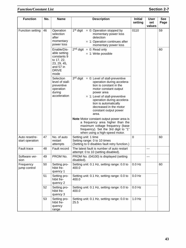
Function setting 46 Operationselectionaftermomentarypower loss
1st digit = 0: Operation stopped bymomentary power lossdetection
= 1: Operation continues aftermomentary power loss
0110 59
Enable/Dis-able settingconstants 9to 17, 22,23, 29, 45,and 57 inDRIVEmode
2nd digit = 0: Read only= 1: Write possible
60
Selectionlevel of stall-preventiveoperationduringacceleration
3rd digit = 0: Level of stall-preventiveoperation during accelera-tion is constant in themotor constant outputpower area
= 1: Level of stall-preventiveoperation during accelera-tion is automaticallydecreased in the motorconstant output powerarea.
Note Motor constant output power area isa frequency area higher than themaximum voltage frequency (basefrequency). Set the 3rd digit to “1”when using a high-speed motor.
Auto reset/re-start operation
47 No. of autorestartattempts
Setting unit: 1 timeSetting range: 0 to 10 times(Setting to 0 disables fault retry function.)
0 60
Fault trace 48 Fault record The latest fault is number of auto restartattempt: 0 to 10 (setting disabled).
---
Software ver-sion
49 PROM No. PROM No. (04100) is displayed (settingdisabled).
---
Frequencyjump control
50 Setting pro-hibit fre-quency 1
Setting unit: 0.1 Hz, setting range: 0.0 to400.0
0.0 Hz 60
51 Setting pro-hibit fre-quency 2
Setting unit: 0.1 Hz, setting range: 0.0 to400.0
0.0 Hz
52 Setting pro-hibit fre-quency 3
Setting unit: 0.1 Hz, setting range: 0.0 to400.0
0.0 Hz
53 Setting pro-hibit fre-quencyrange
Setting unit: 0.1 Hz, setting range: 0.0 to25.5
1.0 Hz
Function/Constant List Section 2-7

44
Function SeePage
Userset
values
Initialsetting
DescriptionNameNo.
Speed searchcontrol
54 Speedsearchdeactivationcurrent level
Setting unit: 1%, setting range: 0 to 200 150% 61
55 Min. base-block time
Setting unit: 0.1 s, setting range: 0.0 to5.0
0.5 s
56 V/F duringspeedsearch
Setting unit: 0.1 s, setting range: 0.0 to100.0
100%
Slip compensa-tion speed con-trol
57 Slip com-pensationfunction
Setting unit: 0.1%, setting range: 0.0 to9.9(100% = Max. Frequency)
0.0% 64
58 Motor no-load current
Setting unit: 0%, setting range: 0 to 99(100% = Motor reated current n%19)
30%
59 Torque com-pensation fil-ter timedelay
Setting unit: 0.1%, setting range: 0.1 to25.5
2 s
Factory setting 60to66
--- Do not set. --- --- ---
Inverter over-load protection
67 OL2 contin-uous opera-tion selec-tion
0: Continuous operation at 103% of ratedcurrent.
1:Continuous operation at 112% of ratedcurrent.
0001 65
Factory setting 68,69
--- Do not set. --- --- ---
Note When setting the third function, set n%0 to 3.
2-8 Description of Functions and Constants
2-8-1 Password Setting
Constant No. 00 is used both to limit read/write access to groups ofconstants and to clear the fault history or initialize constants. Thefollowing tables show the possible values for constant No. 00 andtheir corresponding functions.
Constant no. 00 value Function0 (write-protect setting) Read access: Nos. 00 to 19 only
Write access: No. 00 only1 (initial setting) Read access: Nos. 00 to 19 only
Write access: Nos. 00 to 19 only2 Read access: Nos. 00 to 29 only
Write access: Nos. 00 to 29 only3 Read access: Nos. 00 to 59
Write access: Nos. 00 to 596 Clears the fault history.
Description of Functions and Constants Section 2-8
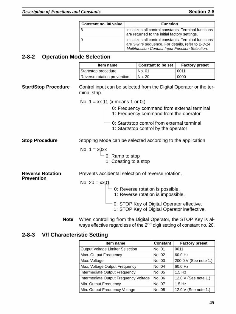
45
Constant no. 00 value Function8 Initializes all control constants. Terminal functions
are returned to the initial factory settings.9 Initializes all control constants. Terminal functions
are 3-wire sequence. For details, refer to 2-8-14Multifunction Contact Input Function Selection.
2-8-2 Operation Mode SelectionItem name Constant to be set Factory preset
Start/stop procedure No. 01 0011
Reverse rotation prevention No. 20 0000
Start/Stop Procedure Control input can be selected from the Digital Operator or the ter-minal strip.
No. 1 = xx 11 (x means 1 or 0.)0: Frequency command from external terminal1: Frequency command from the operator
0: Start/stop control from external terminal1: Start/stop control by the operator
Stop Procedure Stopping Mode can be selected according to the application
No. 1 = x0xx0: Ramp to stop1: Coasting to a stop
Prevents accidental selection of reverse rotation.
No. 20 = xx010: Reverse rotation is possible.1: Reverse rotation is impossible.
0: STOP Key of Digital Operator effective.1: STOP Key of Digital Operator ineffective.
Note When controlling from the Digital Operator, the STOP Key is al-ways effective regardless of the 2nd digit setting of constant no. 20.
2-8-3 V/f Characteristic SettingItem name Constant Factory preset
Output Voltage Limiter Selection No. 01 0011
Max. Output Frequency No. 02 60.0 Hz
Max. Voltage No. 03 200.0 V (See note 1.)
Max. Voltage Output Frequency No. 04 60.0 Hz
Intermediate Output Frequency No. 05 1.5 Hz
Intermediate Output Frequency Voltage No. 06 12.0 V (See note 1.)
Min. Output Frequency No. 07 1.5 Hz
Min. Output Frequency Voltage No. 08 12.0 V (See note 1.)
Reverse RotationPrevention
Description of Functions and Constants Section 2-8

46
In addition, any desired V/f pattern can be set for special specifica-tions.
Any V/f pattern can be set according to the load characteristics.The factory preset value is set to 60 Hz saturation type pattern.
No. 8
No. 6
No. 3
No. 20
No. 8No. 6
No. 3
60 Hz0
12
200 V
1.5 HzNo. 7 No. 5 No. 4No. 2
Freq.
Voltage
Freq.
Voltage(See note 1.)
Factory preset
V/f
patte
rn s
ettin
g
No. 7 No. 5No. 4
Note 1. Values for the 400-V Class are twice those of the 200-V Class.
2. The output voltage will not exceed the upper limit if the outputvoltage limiter function is used. To increase the output voltageignoring the upper limit, do not use the output voltage limiterfunction. For details refer to Output Limiter Selection.
3. If an excessively large value is set in low-speed area (3 Hz orless), motor overheating or Inverter malfunction may occur.
Output Limiter Selection When V/f is set to an excessively large value, an Inverter fault mayoccur. Therefore, in order to prevent malfunction, an upper limitcan be set for the output voltage. However, the setting is not neces-sary under normal operation.
No. 01 = 0xxx4th digit0: Desired V/f with output voltage limiter1: Desired V/f without output voltage limiter
250 V
Frequency
Out
put v
olta
ge
20 V10 V
No. 4No.4 40
(No. 4 = Maximum voltage frequency)
Output voltage limiter pattern
(See
not
e 1)
Note 1. Output voltages of the 400-V-Class are twice those of the200-V-Class.
2. If the 4th digit of constant No. 01 is set to 1, V/f Characteristicmatching the motor characteristics must be set.
Description of Functions and Constants Section 2-8

47
2-8-4 4-step Speed ChangeItem name Constant to be set Factory preset
Multi-speed frequency command No. 13 to No. 16 0.0 Hz for both
Multi-function command No. 32 and No. 33 No. 32 =1, No. 33 = 3
Up to 4 steps of speeds can be set using signals from external ter-minals 4 and 5. This eliminates the need for an analog signalthereby enabling operation by simplified external control. See thefollowing example.
Set according to run specifications.
Frequencycommand 4
Frequencycommand 3
Frequencycommand 2
Frequencycommand 1
Frequencycommand
Terminal
Normal and reverserotation commandTerminal 1 or 2
Multi-speedcommand 1Terminal 4
Multi-speedcommand 2Terminal 5
Time
Open
For 4-step speed
No. 15
No.16
No.13
No. 14
Open
Closed
Closed
Closed
Closed
Open
No. 32 = 3
No. 33 = 4
2-8-5 Jog OperationItem name Constant to be set Factory preset
Jog frequency No. 17 6.0 Hz
Jog reference selection No. 32 or No. 33 No. 32 = 1, No. 33 = 3
The Jog command is input from multifunction contact input termi-nals 4 and 5. Set the value of constant No. 32 to 5 to specify jogoperation for terminal 4, and set the value of constant No. 33 to 5 tospecify jog operation for terminal 5.
Select the Jog Mode (connect terminal 4 or 5 to 6) and input thestart signal. Jog operation starts.
Depressing the JOG Key on the Digital Operator performs thesame operation.
No. 17
ON
ON
ON
Normal rotation 1
Frequency
Jog signal(Terminal 4 or 5)
Forward run rotation signal(Terminal 1)
Reverse run rotation signal(Terminal 2)
TimeReverse rotation
Description of Functions and Constants Section 2-8

48
2-8-6 Accel/Decel Time and Patterns
Item name Constant to be set Factory presetAcceleration time 1 No. 9 10.0 s
Deceleration time 1 No. 10 10.0 s
Acceleration time 2 No. 11 10.0 s
Deceleration time 2 No. 12 10.0 s
Accel/Decel Time Select No. 32 or No. 33 No. 32 = 1, No. 33 = 3
Each item can be set from 0.0 sec to 600.0 sec.
The set time indicates the interval required before the maximumoutput frequency No. 2 is reached.
Time marked with can be set for two-step switching using anexternal contact.
The accel/decel time select command is input from multifunctioncontact input terminals 4 and 5. Set the value of constant No. 32 to6 to specify accel/decel time select operation for terminal 4, andset the value of constant No. 33 to 6 to specify accel/decel timeselect operation for terminal 5.
No. 2
No. 9
No. 12No. 11
Output frequency
No. 10
Between control circuit terminals 4 or 5 and 6.
Open: No. 9 and 10 are selected.
Closed: No. 11 and 12 are selected.
TimeOut
put f
requ
ency
2-8-7 Output Frequency Control (Gain/Bias)
Item name Constant to be set Factory presetFrequency command gain No. 22 1.0
Frequency command bias No. 23 0.00
Output frequency (gain/bias) can be set freely according to fre-quency setting (0 to 10 V or 4 to 20 mA)
No. 22
0
100%
No. 2310 V
(4 mA) (20 mA)
Bias
(100% = 1.00)
Frequency setting
Gain
Description of Functions and Constants Section 2-8
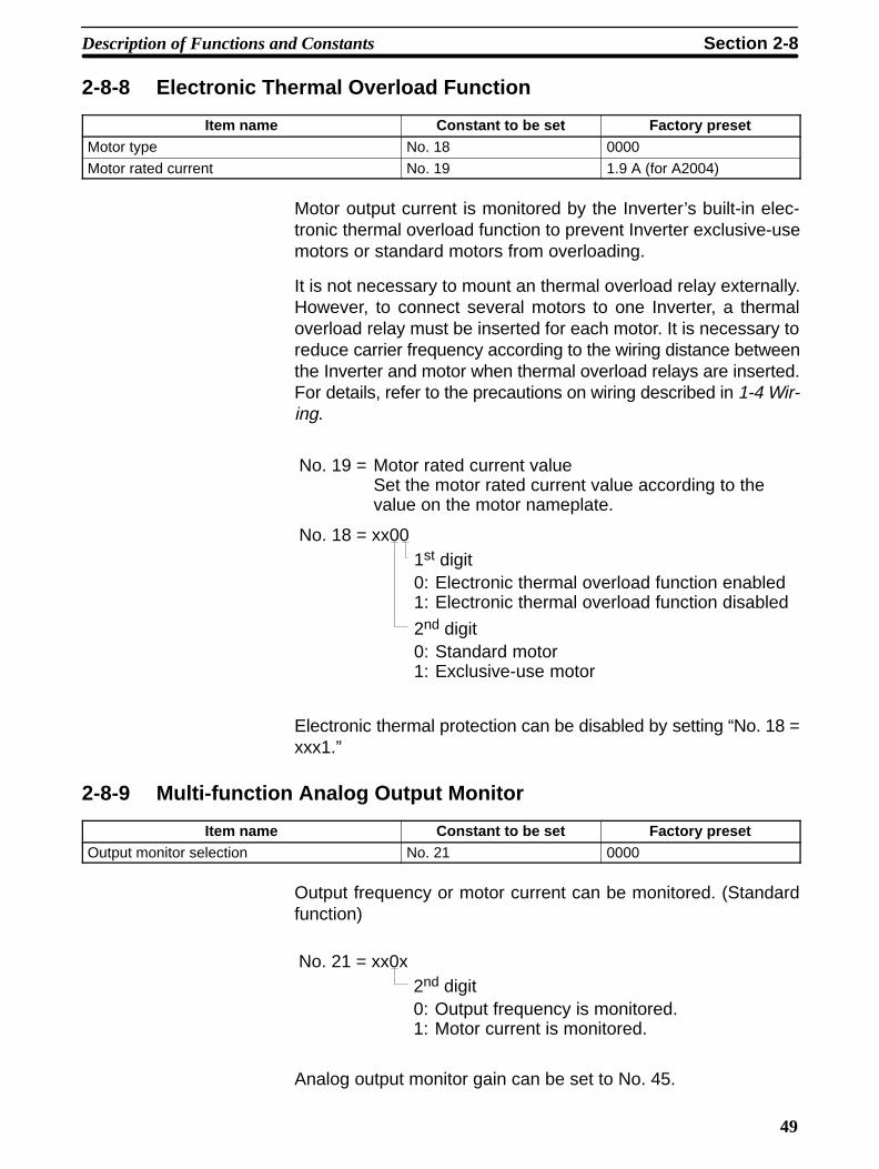
49
2-8-8 Electronic Thermal Overload Function
Item name Constant to be set Factory presetMotor type No. 18 0000
Motor rated current No. 19 1.9 A (for A2004)
Motor output current is monitored by the Inverter’s built-in elec-tronic thermal overload function to prevent Inverter exclusive-usemotors or standard motors from overloading.
It is not necessary to mount an thermal overload relay externally.However, to connect several motors to one Inverter, a thermaloverload relay must be inserted for each motor. It is necessary toreduce carrier frequency according to the wiring distance betweenthe Inverter and motor when thermal overload relays are inserted.For details, refer to the precautions on wiring described in 1-4 Wir-ing.
No. 19 = Motor rated current valueSet the motor rated current value according to thevalue on the motor nameplate.
2nd digit0: Standard motor1: Exclusive-use motor
No. 18 = xx001st digit0: Electronic thermal overload function enabled1: Electronic thermal overload function disabled
Electronic thermal protection can be disabled by setting “No. 18 =xxx1.”
2-8-9 Multi-function Analog Output Monitor
Item name Constant to be set Factory presetOutput monitor selection No. 21 0000
Output frequency or motor current can be monitored. (Standardfunction)
No. 21 = xx0x2nd digit0: Output frequency is monitored.1: Motor current is monitored.
Analog output monitor gain can be set to No. 45.
Description of Functions and Constants Section 2-8

50
2-8-10 Output Frequency LimitItem name Constant to be set Factory preset
Frequency (speed) command upper limit No. 24 100%
Frequency (speed) command lower limit No. 25 0
The upper and lower limits for the output frequency can beclamped. When the lower limit is not 0, acceleration to that lowerlimit setpoint begins immediately when the start command is input.
100%
0 100%
No. 25
No. 24
Output frequency
Frequency command
Note By setting constant No. 24 to 110%, frequencies up to 1.1 times thevalue of constant No. 2 can be output. However, 400 Hz is the high-est frequency that can be output.
For example, assume constant No. 2 = 60 Hz. A frequency of 66 Hzwill be output if constant No. 24 = 1.1.
2-8-11 DC Injection BrakingItem name Constant to be set Factory preset
DC injection braking current No. 26 50%
DC injection during stop No. 27 0.5 s
DC injection at start No. 28 0.0 s
A 100% setting for the DC injection braking current equals theInverter’s rated current. The default setting set at the factory priorto shipping is 50%.
Prevents overrun at stop. (Exact position stop)
No. 7
No. 26
No. 27
Time
Frequency
Current
Time
Stops a coasting motor without tripping even when the direction ofrotation is unknown.
No. 7
No. 26
No. 28
Time
Frequency
Current
Time
DC Injection BrakingCurrent
DC Injection BrakingDuring Stop
Starting DC InjectionBraking During Start
Description of Functions and Constants Section 2-8

51
2-8-12 Motor Stall Prevention FunctionItem name Constant to be set Factory preset
Operation level for stall prevention duringacceleration
No. 30 170%
Operation level for stall prevention during run-ning
No. 31 160%
Stall prevention during deceleration No. 20 0000
Automatically adjusts output frequency according to the load so asto continue operation of the machine without stalling the motor.
Stall Prevention During Acceleration Stall Prevention During Running
Time
Time
Output freq.
Motor current
Reduces speed to prevent motor over-load
No. 31
Suppresses acceleration rateduring this time to prevent stall.
Motor current
Time
Time
output freq.
No. 30
Set “1” for connecting braking resistor unit.
No. 20 = 0xxx0: Stall prevention during deceleration enabled1: Stall prevention during deceleration disabled
When using a high-speed motor that uses the constant power out-put area (with frequency of higher than the maximum voltage fre-quency), the stall prevention operation level must be lowered.
Voltage
Frequency
Constant poweroutput area
Frequency
Operationlevel
V/F Pattern
Constant poweroutput area
Set the third digit of No. 46 to “1.” The Inverter will automaticallylower the operating level to ensure stable operation in the constantpower output area.
Stall Prevention DuringDeceleration
Automatic Drop ofStall PreventionOperation Level DuringAcceleration inConstant PowerOutput Area
Description of Functions and Constants Section 2-8

52
The operation level is lowered according to the following calcula-tion.
OP1= OP2 x VF/OF
OP1:Stall prevention operation level during acceleration in theconstant power output areaOP2:Stall prevention operation level during acceleration (No. 30)VF: Maximum voltage frequency (No. 04)OF: Output frequency
2-8-13 Full-range Automatic Torque Boost
Item name Constant to be set Factory presetTorque compensation gain No. 29 1.0
Automatic control of V/f ratio according to the load torque ensurestripless operation and optimum output current. Normally, noadjustment is necessary. Use this function especially when motorcapacity is smaller than Inverter capacity and torque is required.
100%Torqueincrease
Torquedecrease
Normal frequency
Out
put v
olta
ge
Description of Functions and Constants Section 2-8

53
2-8-14 Multifunction Contact Input Function SelectionItem name Constant to be set Factory preset
Multifunction contact input function No. 32 and No. 33 No. 32 =1, No. 33 = 3
The function of external output terminals 4 and 5 can be changed ifnecessary. Set No. 32 and No. 33 in the descending order.
Terminal 4 function: set No. 32.
Terminal 5 function: set No. 33.
Set value Function0 (see note 1) FWD/REV run command
(3-WIRE sequence selection)1 (see note 2) External fault (NO contact input)
2 External fault (NC contact input)
3 (see note 3) Multi-step speed reference 1
4 Multi-step speed reference 2
5 JOG command
6 Accel/Decel time select
7 External baseblock (NO) contact input
8 External baseblock (NC) contact input
9 Search command from maximum frequency
10 Search command from setting frequency
11 Accel/Decel prohibit command
12 Local/Remote operation
14 (see note4)
UP/DOWN command
Note 1. “0” can be set only to No. 32.2. Factory preset value for No. 323. Factory preset value for No. 334. “14” can be set only to No. 33.5. Contact input capacity is 24 VDC 8 mA or less. Circuit leakage
current at signal OFF must be 100 A or less.
Terminal function at 3-WIRE sequence selection:
3G3XV
1
2
4
6
Run command (run at “closed”)
Stop command (stop at “open”)
FWD/REV run selection(FWD run at “open”, REV run at “closed”)
No. 1 must first be set to 0000 or 0001. If terminal 4 or 5 is closed,local operation from the Digital Operator is in effect. If terminals 4and 5 are open, remote operation from the external terminals is ineffect. Inverter operation must be stopped before switching fromremote to local operation, otherwise the serr is displayed. TheInverter operation, however, is not be affected by the serr mes-sage.
Local/RemoteOperation
Description of Functions and Constants Section 2-8

54
This command is used to increase or decrease the Inverter’s fre-quency using the sequence input.
FWD/STOP
REV/STOP
UP
DOWN
Note When No. 33 is set to ”14” UP/DOWN command, the UP commandwill be allocated to terminal 4 and the settings of No. 32 will beignored.
Run command (FWD/STOP, REV/STOP)
UP command (terminal 4)
DOWN command (terminal 5)
Output frequency Acceleration and decel-eration follow the timeset as acceleration timeor deceleration time.
(See note) (See note)
Terminal 4 ON OFF OFF ON
Terminal 5 OFF ON OFF ON
Accelration Deceleration Hold Hold
Note Once the Run command is input, rotation starts from either theminimum frequency or the lower frequency limit, whichever ishigher.
UP/DOWN Command
Description of Functions and Constants Section 2-8

55
2-8-15 Multifunction Output FunctionItem name Constant to be set Factory preset
Multifunction output function No. 34 and No. 35 No. 34 = 0, No. 35 = 1
Constants No. 34 and No. 35 determine the functions of externaloutput terminals 13 and 14, respectively. (Both of these terminalsare used in connection with terminal 7.)
Set value Function0 (see note 1) In operation
1 (see note 2) Frequency agreed
2 Zero speed
3 Frequency detection(output frequency ≥ frequency detection level)
4 Overtorque detected
Note 1. Factory preset value for No. 342. Factory preset value for No. 35
2-8-16 Frequency/Current Meter CalibrationItem name Constant to be set Factory preset
Analog output gain No. 45 1.00
analog output selection No. 21 0000
Frequency/current meter connected to the Inverter can be cali-brated without using a resistor for calibration.
bn-11+ –
FM12
11
Frequency/current meter(3 V 1 mA full scale)
No. 21 = xx0x0: Output frequency meter1: Output current meter
The analog output monitor gain can be set with constant No. 45.The analog output monitor voltage is calculated from the followingequations. (G= value set in constant No. 45)
Output Frequency Monitor
Output voltage (V) = Output frequency ×Max. output frequency
10 V × G
Output Current Monitor
Output voltage (V) = Output current ×Inverter rated current
10 V × G
Note Since the output current reaches about 200% max. of the Invert-er’s rated current, output voltage is limited to about 11 V max. whenconstant No. 45 is set to 1.00 and the Inverter’s rated current isexceeded. Set constant No. 45 to approx. 0.5 to maintain linearity.
Description of Functions and Constants Section 2-8

56
2-8-17 Overtorque Detection Function
Item name Constant to be set Factory presetOvertorque detection level No. 38 160%
Overtorque detection time No. 39 0.1 s
Overtorque detection signal No. 34 and No. 35 No. 34 = 0, No. 35 = 1
Overtorque detection selection No. 37 0000
When an excessive load is placed on the machine, the increase inmotor current is detected and alarm signal can be output.
If the current exceeds the value set in No. 38 for longer than thetime limit set in No. 39, the overtorque detection signal is output tocontrol circuit terminal 13 or 14 until the current falls below thevalue set in No. 38.
To output the signal to control circuit terminal 13, set constant No.34 to 4. To output the signal to control circuit terminal 14, set con-stant No. 35 to 4.
Time
Overtorque detection signal
Motor current
No. 39
ON ON
No. 39
No. 38
The second digit of No. 37 determines whether overtorque will bedetected during acceleration and deceleration, and the third digitdetermines whether overtorque will be treated as a fault (OL3) oroperation will continue after overtorque is detected.
2nd digit0: Detection only at steady speed1: Detection during accel/decel also
No. 37 = x0011st digit0: Overtorque detection disabled1: Overtorque detection enabled
3rd digit0: Operation after overtorque detection1: Output shut off after overtorque detection
Description of Functions and Constants Section 2-8

57
2-8-18 Carrier Frequency
Item name Constant to be set Factory presetCarrier frequency upper limit No. 40 4
Changing the carrier frequency reduces RFI noise and leakagecurrent without increasing motor noise.
Carrier frequency (kHz) = 2.5 kHz × constant No. 40 value
6
1
0
No. 40
Carrier frequency: Factory setting prior to shipment
Output frequency
1 2 3 4 5 6
Carrier frequency(LOW) (HIGH)
Metallic noisefrom motor
(Rather high) (Not audible)
4
Note Reduce continuous output current for changing the frequency to 5or 6.
Carrier FrequencySet Value
Maximum Continuous Output Current
1 to 4 Up to 100% of Inverter output current
5 Up to 90% of Inverter output current
6 Up to 80% of Inverter output current
If the wiring distance between the Inverter and motor is long,reduce the carrier frequency. For details, refer to the wiring precau-tions described in 1-4 Wiring.
2-8-19 Speed Agreed Signal Output
Item name Constant to be set Factory presetFrequency detection level No. 36 0.0 Hz
Multifunction contact output function No. 34 and No. 35 No. 34 = 0, No. 35 = 1
This function is used when operation at an arbitrary speed must beindicated. Set the multifunction contact output (No. 34, No. 35) asfollows:
Set Value = 1: Frequency Agreed
Detection width2 Hz
Output frequency
Frequency agreed signal
Release width4 HzFrequencyreference
Closed
Description of Functions and Constants Section 2-8

58
Set Value = 3: Set Value or More
Output frequency
Frequency detection signal
Release width–2 Hz
Closed
No. 36
2-8-20 S-curve at Accel/Decel Time
Item name Constant to be set Factory presetS-curve at accel/decel time No. 21 0000
The S-curve characteristics of the soft starter depend on the set-ting of digits 3 and 4 of No. 21, as follows:
4th digitNo. 21 = 00xx
3rd digit0 0: No S-curve characteristic (linear accel.)0 1: The S-curve characteristic is 0.2 s.1 0: The S-curve characteristic is 0.5 s.1 1: The S-curve characteristic is 1 s.
Output frequency
S-curve characteristicstime(TSC)
Frequency ref.
Time
Digit 3, Digit 4 (S-curveSelection of SoftStarter)
Description of Functions and Constants Section 2-8

59
Note S-curve characteristics time refers to the time from accelerationrate 0 to the time when a normal acceleration rate determined by aspecified acceleration time is obtained.
Time chart at FWD/REV run change with S-curve characteris-tics:
The figure below shows the time chart at FWD/REV run changeduring deceleration and stop.
FWD RUN command
REV RUN command
Output frequencyMin. output frequencyNo-07
Acceleration Deceleration DC injection brakingtime stoppingNo-27
Min. outputfrequencyNo-07
Acceleration Deceleration: S-curve characteristic
Note When digits 3 and 4 are 00, no S-curve characteristics at comple-tion of deceleration.
Time chart at FWD/REV run change without S-curve charac-teristics:
The figure below shows the time chart at FWD/REV run changeduring deceleration and stop.
FWD RUN command
REV RUN command
Output frequencyMin. output frequencyNo-07
Acceleration Deceleration DC injection brakingtime at stoppingNo-27
Min. outputfrequencyNo-07
Acceleration Deceleration
2-8-21 Other FunctionsItem name Constant to be set Factory preset
Function setting No. 46 0110
Digit 1 = 0: When momentary stop is detected, power failure (UVfault) occurs and the Inverter output is shut off.
Digit 1 = 1: If momentary stop time is within momentary assurancetime (see note), the operation continues after the momentary stop.If the momentary assurance time is exceeded, the Inverter outputis shut off.
Operation Continuedat Momentary Stop
Description of Functions and Constants Section 2-8

60
Note 0.75 kW max.: Approximately 1 s.1.5 kW max.: Approximately 2 s.
Digit 2 = 0: Constant setting is disabled during running
Digit 2 = 1: Constant setting is enabled during running(no-09 to no-17, no-22, no-23, no-29, no-45 are enabled)
Digit 3 = 0: Level of stall-preventive operation during accelerationis constant in the motor constant output power area
Digit 3 = 1: Level of stall-preventive operation during accelerationis automatically decreased in the motor constant output powerarea.
Note Motor constant output power area is a frequency area higher thanthe maximum voltage frequency (base frequency). Set the 3rd digitto “1” when using a high-speed motor.
2-8-22 Enable/Disable Setting Constants in DRIVE ModeItem name Constant to be set Factory preset
Enable/Disable setting constants 9 to 17, 22,23, 29, 45, and 57 in DRIVE mode
No. 46 0
Digit 2 = 0: Read only
Digit 2 = 1: Write possible
2-8-23 No. of Auto Reset/Restart Operation (No. 47)Item name Constant to be set Factory preset
Fault retry selection No. 47 00
Sets the number of auto reset/restart tries (up to 10). Setting thisconstant to zero disables the auto reset/restart operation.
Each time a OC, OV, OH , or GF fault occurs, the number of autoreset/restart tries is incremented by one. If this number reachesthe value set in No. 47, another auto reset/restart attempt is notmade.
The number of auto reset/restart tries is cleared to zero when:
• No fault occurs for 10 minutes.• A fault reset signal is input from external terminals or Digital
Operator.• Power is turned off.
Note GF is for Single-phase Input Models only.
2-8-24 Setting Prohibit Frequency Range (No. 50 to No. 53)Item name Constant to be set Factory preset
Jump Frequency 1 No. 50 0.0 Hz
Jump Frequency 2 No. 51 0.0 Hz
Jump Frequency 3 No. 52 0.0 Hz
Jump width No. 53 1.0 Hz
Enable/Disable SettingConstants in DRIVEMode
Selection Level of StallPreventive OperationDuring Acceleration
Description of Functions and Constants Section 2-8

61
Set the range of setting prohibit frequency in the units of 0.1 Hz.The range of the setting prohibit frequency is determined as fol-lows, depending on combinations with No. 50 to No. 52.
No. 50 to No. 52 – No. 53 ≤ the range of the setting prohibit fre-quency ≤ No. 50 to No. 52 + No. 53
Setting prohibitfrequency
Setting prohibitfrequency
Setting prohibitfrequency
Setting prohibitfrequency Range
Internal frequencyREF.
No. 53
No. 51
No. 50
No.52
Setting frequency ref.
See note 2
Note 1. Constant-speed operation is prohibited in the setting prohibitfrequency range. Output frequency does not jump duringacceleration or deceleration, which is performed smoothly.,
2. Set as follows; No. 50 ≥ No. 51 ≥ No. 52
2-8-25 Speed Search Function
Item name Constant to be set Factory presetMultifunction contact input function No. 32, 33 ---
Speed search deactivation current level No. 54 150%
Minimum baseblock time No. 55 0.5 s
V/f during speed search No. 56 100%
When search command is “closed” during baseblock, speedsearch is started after Inverter output is shut off for the minimumbaseblock time.
Search commands with set values of 9 and 10 cannot be set at thesame time.
Set value = 9: Speed search starts with the maximum frequency.
Search Command (SetValue = 9, 10) (No. 32or No. 33)
Description of Functions and Constants Section 2-8

62
Set value = 10: Speed search starts with the frequency referencevalue when search command is input.
FWD(REV) RUN com-mandSEARCH command
Max. frequency or fre-quency ref. value whenSEARCH command isinput
Output frequency
Min. baseblocktime
Voltage at speed search
Output voltageSpeed searchoperation
Return to the voltageat normal running
Speed synchronizationdetection
0.5 sec. or less
Note 1. In Momentary Stop Operation Continuation Mode, speedsearch operation is performed beginning with current outputfrequency, regardless of the existence of search command.After completion of speed search, the operation is performedaccording to the run command.
2. Determine a sequence so that FWD/REV run command entersat the same time or later than search command.
Example of Sequence
Relay 1 Relay 2
Relay 1
SEARCH command
FWD/REV RUN command
When Inverter output current immediately after power recovery islarger than the set value of No. 54, speed search operation isstarted. When Inverter output current is smaller than the set valueof No. 54, the frequency is interpreted as a speed synchronizationpoint and acceleration or deceleration is performed again up to aspecified frequency.
On detecting momentary power loss, the Inverter shuts off outputand maintains the baseblock state for a given time. Set in No. 55the time when motor residual voltage is expected to be almostzero.
Speed SearchDeactivation CurrentLevel (No. 54)
Minimum BaseblockTime (No. 55)
Description of Functions and Constants Section 2-8

63
When momentary power loss time is longer than the minimumbaseblock time, speed search operation is started immediatelyafter power recovery.
Momentary powerloss time
Min.baseblock time
Inverter baseblocktime
Momentary powerloss time
Min.baseblock time
Inverter baseblocktime
When min. baseblocktime is longer thanmomentary power losstime.
When min. baseblocktime is shorter thanmomentary power losstime.
To ensure that a fault such as OC does not occur during speedsearch operation, V/f must be reduced during speed search opera-tion, as compared with that during normal operation. Set V/f duringspeed search as follows by the set value of No. 56:
V/f during speed search = V/f at normal operation x No. 56
2-8-26 Accel/Decel Prohibit Function
Item name Constant to be set Factory presetAccel/Decel Prohibit Function No. 32 and No. 33 No. 32 = 1, No. 33 = 3
When an accel/decel prohibit command is input during accelera-tion or deceleration, the output frequency is maintained and accel-eration or deceleration is stopped as long as the input is beingreceived.
If a stop command is received while the accel/decel prohibit com-mand is being received, the accel/decel prohibit command will beoverridden and operation will be stopped.
The accel/decel prohibit command can be input from multifunctioncontact input terminals 4 and 5. Set the value of constant No. 32 to8 to specify an accel/decel prohibit command for terminal 4, andset the value of constant No. 33 to 6 to specify an accel/decel pro-hibit command for terminal 5.
The following time chart shows the operation of the accel/decelprohibit command:
FWD RUN
ACCEL/DECELPROHIBIT Command
FrequencyReference
Frequency AgreedSignal
OutputFrequency
V/f During SpeedSearch (No. 56)
Description of Functions and Constants Section 2-8

64
Note When the FWD (REV) run command is input in the status wherethe accel/decel prohibit command is input, the baseblock status iscontinued and the motor does not operate.
The motor will operate at the frequency set in constant No. 25 (fre-quency lower limit) when No. 25 ≥ No. 07 (minimum output fre-quency).
2-8-27 Slip Compensation Speed ControlItem name Constant to be set Factory preset
Slip Compensation Function No. 57 0%
Motor No-load Current No. 58 30%
Torque Compensation Filter Time Delay No. 59 ---
• The slip compensation function keeps the rotating speed of themotor constant if the load is heavy. Without this function, themotor will slip and the rotating speed of the motor will decrease ifthe load is heavy.
• If the output current of the Inverter is equal to the electronic ther-mal reference current (i.e., the rated current of the motor), addthe compensation frequency equivalent to the rated slippagevalue of the motor to the output frequency.
• Refer to the following formulas to obtain the constants to be set inno-57 and no-58.no-57 = (Synchronization speed – rated motor revolution)/syn-chronization speed x 100Synchronization speed = 120/P fP: No. of pollsf: Rated frequencyno-58 = (Output current with no load/rated current of the motor) x100
• The compensation frequency (fc) can be obtained from the fol-lowing.
If the output frequency is lower than the constant set in no-04for the maximum voltage frequency, use the following formulato obtain the compensation frequency (fc).fc = no-04 x no-57 x [output current – (no-19 xno-58/100)]/[no-19 x no-58/100)]If the output frequency is equal to or higher than the constantset in no-04 for the maximum voltage frequency, use the follow-ing formula to obtain the compensation frequency (fc).fc = output frequency x no-57 x [output current – (no-19 xno-58/100)/[no-19 – (no-19 x no-58/100)no-04: Maximum voltage frequency (Hz)no-19: Electronic thermal reference current (A)
Note 1. The slip compensation function does not work if the output fre-quency is lower than the constant set in no-07 for the minimumoutput frequency.
Description of Functions and Constants Section 2-8

65
2. The slip compensation function does not work if the Inverter isin regenerative operation.
3. The slip compensation function dows not work if 0.0 is set forthe electronic thermal reference current.
• no-59 = Set to a small value if the response is slow and adjust toa large value if vibration occurs.
2-8-28 Inverter Overload Protection
Item name Constant to be set Factory presetOL2 Continuous Operation No. 67 1
The Inverter output is shut-off when electronic thermal overloadreaches or exceeds the inverse time limit of either 103% or 112% ofthe Inverter’s rated current occurs.
Set value = 0: Continuous operation at 103% of rated current.
Set value = 1: Continuous operation at 112% of rated current.
Note When setting to the set value “1” (continuous operation at 112% ofrated current), be sure to set the carrier frequency (No. 40, carrierfrequency adjustment) to less than 10 kHz (or to the set value of 4or less).
Description of Functions and Constants Section 2-8

67
SECTION 3Troubleshooting and Maintenance
This section describes troubleshooting, inspection, and maintenance procedures.
3-1 Fault Display 66. . . . . . . . . . . . . . . . . . . . . . . . . . . . . . . . . . . . . . . . . . . . . . . 3-1-1 Protection Functions 66. . . . . . . . . . . . . . . . . . . . . . . . . . . . . . . . . . . 3-1-2 Warning and Self-diagnosis Functions 68. . . . . . . . . . . . . . . . . . . . .
3-2 Correcting Motor Faults 69. . . . . . . . . . . . . . . . . . . . . . . . . . . . . . . . . . . . . . . 3-3 Maintenance 70. . . . . . . . . . . . . . . . . . . . . . . . . . . . . . . . . . . . . . . . . . . . . . . .
3-3-1 Periodic Inspection 70. . . . . . . . . . . . . . . . . . . . . . . . . . . . . . . . . . . . . 3-3-2 High Voltage Test 70. . . . . . . . . . . . . . . . . . . . . . . . . . . . . . . . . . . . . . 3-3-3 Installing/Removing the Digital Operator 71. . . . . . . . . . . . . . . . . . .

68
3-1 Fault Display
3-1-1 Protection FunctionsProtection function Explanation Monitor
displayFault con-tact output
Low voltageprotection
Main circuitvoltagelow
When the Inverter power voltage drops, torquebecomes insufficient and motor is overheated. Inverteroutput is stopped when the main circuit DC voltagebecomes lower than the low voltage detection level for15 ms or longer. Detection level: approximately 210 V or less
(200 V, 3-phase)approximately 170 V or less(200 V, single-phase)approximately 420 V or less(400 V, 3-phase)
uU1 (UV1) Operation
Overcurrent protection
The Inverter output is shut-off when the Inverter outputcurrent becomes approx. 200% and above of Inverterrated current.
%c (OC) Operation
Ground-fault protection
The Inverter output is shut-off when a ground-faultoccurs at the Inverter output side.
gf (GF) Operation
Overvoltage protection
The Inverter output is shut-off when the main circuitDC voltage becomes excessive because of regenera-tion energy caused by motor deceleration and negativeload.Detection level: approx. 410 V or more (200 V class)
approx. 820 V or more (400 V class)
%U (OV) Operation
Fuse blown The Inverter output is shut-off when the main circuittransistor fails.The fuse clears to prevent wiring from being damagedby the short-circuit current.
(Not displayed) Non opera-tion
Cooling fin overheat The Inverter output is shut-off when the ambient tem-perature rises and the heat sink fin reaches 90°C.Please check for a defective cooling fan or cloggedfilter.
%h (OH) Operation
Overloadprotection
Motor Inverter output is stopped when motor overload isdetected by the electronic thermal overload in theInverter. Either a Inverter duty constant-torque special-ized motor or general-purpose motor can be selected.If more than one motor is drive, overload protectionshould be disabled. Use a thermal relay or thermal pro-tector for each motor.
%l1 (OL1) Operation
Inverter The Inverter output is shut-off when electronic thermaloverload reaches or exceeds the inverse time limit of112% of the Inverter’s rated current occurs. Maximumrated overload: 150%, 1 min.
%l2 (OL2) Operation
Overtorquedetection
The motor operates according to a preset mode whenthe Inverter output current exceeds the overtorquedetection level. This function is used to protect themachine or to monitor the output torque.
%l3 (OL3) Operation
External fault signalinput
When an external alarm signal is input, the Inverteroperates according to a preset stop method (coastingto a stop, or ramp to stop)
ef4 (EF4)ef5 (EF5)
Operation
Control circuit faultthermistor fault
The Inverter output is shut-off when a transmissionerror occurs in the control circuit or a component fails.
cpf00 to cpf05*(see note)
Operation
Note * indicates the content of Digital Operator display
Fault Display Section 3-1

69
Protection func-tion
Error causes Action to be taken
Low voltageprotec-tion
Main circuitvoltagelow
Inverter capacity is too small.Voltage drop due to wiring.A motor of large capacity (11 kW orgreater) connected to the same powersystem has been started.Rapid acceleration with generatorpower supplyOperation sequence when power is offDefective electromagnetic contactor
Check the power capacity and power sys-tem.UV display appears when the Inverter poweris turned off while operation signal is input.Remove the power after stopping theInverter.
Overcurrent protection
Extremely rapid accel/decelMotor on/off switching at the Inverteroutput sideMotor of a capacity greater than theInverter rating has been started.High-speed motor or pulse motor hasbeen started.Inverter output has been short cir-cuited.
Transistor error may occur. Investigate theerror cause, correct it, then restart.
Ground-fault protection
Ground-fault at the Inverter output side
Overvoltage protection
Over voltageInsufficient deceleration timeRegenerative load (Motor is turned bythe load.)High input voltage compared to motorrated voltage
If braking torque is not proper, extend thedecel time or use a braking resistor.
Fuse blown Repeated overcurrent protection (OC)Repeated overload protection (OL2)power resetRapid deceleration in excess excitation(improper V/f characteristic setting)
Turn off the power supply once and turn iton again. If the fault occurs again after replacement,replace the Inverter.
Cooling fin overheat Defective cooling fanAmbient temperature riseClogged filter
Replace the cooling fan and clean the filter.Ambient temperature: 104°F (40°C) or less[113°F (45°C) or less with top cover off]
Overloadprotec-tion
Motor Overload, low speed operation orextended acceleration time, improperV/f characteristic setting
Investigate the cause of overload andreview the operation pattern, V/f characteris-tic, and motor/inverter capacities.
Inverter (If Inverter is repeatedly reset after an over-load occurs, the Inverter may fault. Investi-gate and correct the cause of overload.)
Overtorquedetec-tion
Motor current exceeds the preset valuebecause of machine error or overload
Check the use of the machine. Correct theoverload cause or set a higher detectionlevel which is within the allowable range.
External fault signalinput
External fault condition occurred. Correct the cause of the fault input.
Control circuit faultthermistor fault
External noiseExcess vibration or shock
Record all data of cpf04, then make initial-ization.Turn off power, then turn on again. If error ispersistent, replace the Inverter.
Fault Display Section 3-1

70
3-1-2 Warning and Self-diagnosis Functions
Protection function Explanation Monitordisplay
Fault con-tact output
Low-voltage protection(main circuit voltageinsufficient)
Monitor display appears when the main circuit DCvoltage drops under the detection level while theInverter output is off.
(UV)uU (Blink)
Non operation
Overtorque detection This function is used to protect the machine and tomonitor the Inverter’s output torque.The Inverter output reacts in a preset manner whenthe Inverter output current exceeds the over torquedetection level. The monitor display blinks when“operation continue” is preset.
(OL3)%l3 (Blink)
Non operation
Stall pre-vention(Accel/decelis accom-plished withmaximumcapacity ofthe Inverter
Duringaccelera-tion
Inverter acceleration is stopped when 170% of ormore of the Inverter rated current is required by theload.This prevents overload protection (OL2) or overcur-rent (OC) from occurring.When current is reduced to less than 170%, accel-eration is enabled.
--- Non operation
the Inverterwithout trip-ping onovercurrentor overvol-tage.)
During nor-mal opera-tion
Output frequency is decreased when 160% of theInverter rated current or greater is required by theload. This prevents motor and Inverter overload(OL1, OL2). When current is reduced below 160%,Inverter acceleration is then enabled.
Duringdecelera-tion
Deceleration is stopped when the DC voltage iscaused to rise by motor regenerative energy.This prevents overvoltage trips (OV). When DC volt-age decreases, deceleration to the set value thenresumes.
Simultaneous forwardand reverse rotation com-mands
When forward and reverse rotation commands aresimultaneously detected for a period of time exceed-ing 500 ms, the Inverter is stopped according to thepreset stop method.
(EF)ef (Blink)
Non operation
External base block sig-nal input (main circuittransistor instantaneousshut-off)
When an external base block signal is input, themotor coasts to a stop. When the external base blocksignal is removed, the Inverter output is immediatelyturned on at the previously set frequency.
(BB)bb (Blink)
Non operation
Fault Display Section 3-1

71
Protection function Error causes Action to be takenLow-voltage protection(main circuit voltageinsufficient)
Input voltage drop Check the input power supply voltageusing a tester. If the voltage is low,adjust the input voltage.
Overtorque detection Motor current exceeded the set valuebecause of machine fault or overload.
Check the driven machine and correctthe cause of the fault or set to a highervalue.
Stall pre-vention(Accel/decelis accom-plished withmaximumcapacity ofthe Inverter
Duringaccelera-tion
Insufficient power for accel/decelOverloadPhase loss
Set proper accel/decel time for smoothoperation.For stall prevention during normaloperation lighten the load or increaseInverter capacity.
the Inverterwithout trip-ping onovercurrentor overvol-tage.)
During nor-mal opera-tion
Duringdecelera-tion
Simultaneous forwardand reverse rotation com-mands
Operation sequence error3-wire/2-wire selection error
Recheck the control sequence.Recheck constant settings (No. 32).
External base block sig-nal input (main circuittransistor instantaneousshut-off)
--- ---
3-2 Correcting Motor FaultsThe following table lists possible causes and corrective actions forfaults that might occur.
Fault Possible Cause Corrective ActionMotor does notrotate.
Power supply voltage is not supplied topower supply terminals L1 (R), L2 (S), andL3 (T). (The CHARGE indicator should beon.)
Turn on power supply.
Turn power supply off and then on again.
Check power supply voltage.
Voltage is not being output to output termi-nals T1 (U), T2 (V), and T3 (W).
Turn power supply off and then on again.
Load is too large. (Motor is locked.) Reduce the load. (Release the lock.)A fault is displayed. Correct the fault as described in 3-1 Fault
Display.FWD or REV run command has not beenentered.
Correct the wiring.
Frequency setting signal has not beenentered.Operation (method selection) Mode settingis incorrect.
Use the Digital Operator to check theOperation Method Selection Mode.
Motor rotating inwrong direction.
Wiring of output terminals T1 (U), T2 (V),and T3 (W) is incorrect.
Make sure that the terminals’ phase ordermatches the motor terminals’.g
Wiring of FWD or REV run signals is incor-rect.
Correct the wiring.
Correcting Motor Faults Section 3-2

72
Fault Corrective ActionPossible CauseMotor rotates, butvariable speed
Wiring of frequency setting circuit is incor-rect.
Correct the wiring.
does not work. Load is too large. Reduce the load.Motor speed istoo high (low)
Motor ratings (number of poles, voltage)are incorrect.
Check motor specifications and name-plate.g ( )
Accel/decel ratio by speed converter(gears, etc.) is incorrect.
–––
Maximum frequency set value is incorrect. Check the maximum frequency set value.Voltage drops excessively between motorterminals.
Check the base frequency.
Motor speed isbl
Load is too large. Reduce the load.unstable Excessive load variation. Reduce load variation.
Increase Inverter or motor capacity.
3-3 Maintenance
3-3-1 Periodic Inspection
The 3G3XV requires a few routine checks to ensure trouble-freeoperation. Be sure that the 3G3XV is kept clean, cool, and dry, andfollow the recommendations given in 1-3-1 Location.
Before inspecting the Unit, turn off the power and make sure thatthe CHARGE indicator is off.
Component Check For Corrective ActionTerminals, Unit mountingbolts, connectors, etc.
Loosened screws or connectors Tighten
Cooling fins Build-up of dust and dirt Clean off with dry compressed air at apressure of 57 to 85 psi (4 to 6 kg⋅cm2).
Printed circuit board Accumulation of dust or oil Dust and oil can conduct electricity. Cleanthe board if necessary. Replace Inverterunit if dust and oil cannot be removed.
Cooling fan Abnormal noise or vibration Replace cooling fan
Power components Build-up of dust and dirt Clean off with dry compressed air at apressure of 57 to 85 psi (4 to 6 kg⋅cm2).
Smoothing capacitor Discoloration or odor Replace capacitor or Inverter.
3-3-2 High Voltage Test
Use an insulation resistance tester (500 V) to conduct an insulationresistance test (high voltage test) on the main control circuit, asdescribed below.
1, 2, 3... 1. Remove the Inverter’s main circuit and control circuit terminalwiring and perform the test only between the main circuit termi-nals and ground G (E), as shown in the following figure.
Maintenance Section 3-3

!
73
2. The equipment is normal if the insulation resistance tester indi-cating 1 MΩ or more.
3G3XV
L1 L2 L3 T1 T2‘ T3(R)(S)(T)(U)(V)(W)
B1/B2
G(E)
Caution Do not conduct a high voltage test on the control circuit terminals.
3-3-3 Installing/Removing the Digital Operator
Follow the procedures below to install or remove the Digital Opera-tor. The Digital Operator must not be installed or removed whilepower is on; be sure to turn off the Inverter’s power supply andcheck that the CHARGE indicator is off.
Operator Installation Insert the Digital Operator directly into the Inverter as shown in thefollowing figure.
Operator Removal
1, 2, 3... 1. Remove the terminal cover by simultaneously squeezing thesides (1) and lifting (2), as shown below.
(1)
(1)
(2)
Maintenance Section 3-3

74
2. Press the lever down (3) and insert a standard screwdriver inslot A, as shown below, then lift the operator up (4) and out ofthe Inverter.
Lever Operator
A
(3)
(4)
Maintenance Section 3-3

75
Revision History
A manual revision code appears as a suffix to the catalog number on the front cover of the manual.
Cat. No. I005-E1-2
Revision code
The following table outlines the changes made to the manual during each revision. Page numbers refer to theprevious version.
Revision code Date Revised content
1 March 1993 Original production
1A July 1993 Page 5: Data in the table has been corrected.Pages 9, 11, 12: Inverter capacities in the tables havebeen corrected.Pages 21, 23: Output characteristics’ inverter capaci-
ties in the tables have been corrected.Pages 22, 24: Weight data in the tables has beencorrected.
1B March 1994 Pages 7, 14: Terminal 8 in the wiring diagram cor-rected to 0 to +10 VDC (2 KΩ).Page 37: First digit of constant no. 1 corrected to ter-minals 8 and 9.
Page 47: Third digit for constant no. 18 corrected toreflect that it is not used.Page 57: Set values in the heading for Search Com-mand corrected to “Set Value = 9, 10.”
1C January 1996 Page 3: “Enclosed type” and “open-chassis type”changed to “with top cover on” and “with top cover off,”respectively.Page 13: “Power supply coordination AC reactor”replaced with “AC reactor.” Diagram corrected.Page 21: Stall prevention level specification corrected.Page 25: Radio noise protective filter function cor-rected.Page 29: Constants that can be changed in DRIVEMode have been added.Page 33: Row where 00 = 5 added.Page 34: Note 2 added.Page 37: Set value 5 added to No. 0.Page 38: References to note 2 added to No. 9 to No.12.
Page 39: Setting range of torque compensationincreased to 9.0. Note 2 added.Page 40: Set values added to No. 32 and No. 33. Ini-tial setting for No. 33 corrected to 3.Page 41: 2nd digit for constant 46 added. PROM No.added for constant 49.Page 42: No. 57 to No. 59 and No. 67 added. Note 1deleted.Page 50: Set values and note 4 added.Page 51: Local/Remote Operation and UP/DOWNCommand added.Page 56: 2-8-22 Enable/Disable Setting Constants inDRIVE Mode added.Page 59: 2-8-26 Slip Compensation Speed Controland 2-8-27 Inverter Overload Protection added.
2 November 1997 Model number suffix “-E” changed to “EV2” throughout the manual.
Page 3: “Potentiometers” corrected to “constants” in caution.Page 9: Settings when a ground fault interrupter is used have been corrected in Mold-case Circuit Breaker (MCCB).Page 10: Caution on withstand voltage added.Page 13: “Acceptable” grounding example removed.Page 24: Note added to 1-6-3 Optional Units.Page 37: Setting range corrected for constant numbers 27 and 28 of “DC injection brak-ing.”Page 38: “5: Operation mode” added to constant numbers 34 and 35 of “Photocoupleroutput signal.”Page 39: 3rd digit information and note added to constant number 46. Initial setting cor-rected.Page 40: Descriptions for “Slip compensation speed control” (constant numbers 57 to59) corrected. Factory settings added (constant numbers 60 to 66, 68, and 69).Page 47: Information added to 2-8-12 Motor Stall Prevention Function.Page 49: Information for UP/DOWN Command changed.Page 54: 2-8-21 Momentary Power Loss Protection changed to 2-8-21 Other Functions.Page 56: “Residual voltage” corrected to “motor residual voltage’ in Minimum BaseblockTime (No. 55).Page 58: Information in 2-8-27 Slip Compensation Speed Control changed and addedto. Note added to 2-8-28 Inverter Overload Protection.Page 61: Information for the low voltage protection, overcurrent protection, and coolingfin overheat protection functions corrected.Pages 62, 63: “Simultaneous normal and reverse rotation commands” corrected to“Simultaneous forward and reverse rotation commands.”Page 63: Information for “Low-voltage protection (main circuit voltage insufficient)” and“Simultaneous forward and reverse rotation commands” corrected.

Terms and Conditions of Sale1. Offer; Acceptance. These terms and conditions (these "Terms") are deemed
part of all quotes, agreements, purchase orders, acknowledgments, price lists,catalogs, manuals, brochures and other documents, whether electronic or inwriting, relating to the sale of products or services (collectively, the "Products")by Omron Electronics LLC and its subsidiary companies (“Omron”). Omronobjects to any terms or conditions proposed in Buyer’s purchase order or otherdocuments which are inconsistent with, or in addition to, these Terms.
2. Prices; Payment Terms. All prices stated are current, subject to change with-out notice by Omron. Omron reserves the right to increase or decrease priceson any unshipped portions of outstanding orders. Payments for Products aredue net 30 days unless otherwise stated in the invoice.
3. Discounts. Cash discounts, if any, will apply only on the net amount of invoicessent to Buyer after deducting transportation charges, taxes and duties, and willbe allowed only if (i) the invoice is paid according to Omron’s payment termsand (ii) Buyer has no past due amounts.
4. Interest. Omron, at its option, may charge Buyer 1-1/2% interest per month orthe maximum legal rate, whichever is less, on any balance not paid within thestated terms.
5. Orders. Omron will accept no order less than $200 net billing. 6. Governmental Approvals. Buyer shall be responsible for, and shall bear all
costs involved in, obtaining any government approvals required for the impor-tation or sale of the Products.
7. Taxes. All taxes, duties and other governmental charges (other than generalreal property and income taxes), including any interest or penalties thereon,imposed directly or indirectly on Omron or required to be collected directly orindirectly by Omron for the manufacture, production, sale, delivery, importa-tion, consumption or use of the Products sold hereunder (including customsduties and sales, excise, use, turnover and license taxes) shall be charged toand remitted by Buyer to Omron.
8. Financial. If the financial position of Buyer at any time becomes unsatisfactoryto Omron, Omron reserves the right to stop shipments or require satisfactorysecurity or payment in advance. If Buyer fails to make payment or otherwisecomply with these Terms or any related agreement, Omron may (without liabil-ity and in addition to other remedies) cancel any unshipped portion of Prod-ucts sold hereunder and stop any Products in transit until Buyer pays allamounts, including amounts payable hereunder, whether or not then due,which are owing to it by Buyer. Buyer shall in any event remain liable for allunpaid accounts.
9. Cancellation; Etc. Orders are not subject to rescheduling or cancellationunless Buyer indemnifies Omron against all related costs or expenses.
10. Force Majeure. Omron shall not be liable for any delay or failure in deliveryresulting from causes beyond its control, including earthquakes, fires, floods,strikes or other labor disputes, shortage of labor or materials, accidents tomachinery, acts of sabotage, riots, delay in or lack of transportation or therequirements of any government authority.
11. Shipping; Delivery. Unless otherwise expressly agreed in writing by Omron:a. Shipments shall be by a carrier selected by Omron; Omron will not drop ship
except in “break down” situations.b. Such carrier shall act as the agent of Buyer and delivery to such carrier shall
constitute delivery to Buyer;c. All sales and shipments of Products shall be FOB shipping point (unless oth-
erwise stated in writing by Omron), at which point title and risk of loss shallpass from Omron to Buyer; provided that Omron shall retain a security inter-est in the Products until the full purchase price is paid;
d. Delivery and shipping dates are estimates only; ande. Omron will package Products as it deems proper for protection against nor-
mal handling and extra charges apply to special conditions.12. Claims. Any claim by Buyer against Omron for shortage or damage to the
Products occurring before delivery to the carrier must be presented in writingto Omron within 30 days of receipt of shipment and include the original trans-portation bill signed by the carrier noting that the carrier received the Productsfrom Omron in the condition claimed.
13. Warranties. (a) Exclusive Warranty. Omron’s exclusive warranty is that theProducts will be free from defects in materials and workmanship for a period oftwelve months from the date of sale by Omron (or such other period expressedin writing by Omron). Omron disclaims all other warranties, express or implied.(b) Limitations. OMRON MAKES NO WARRANTY OR REPRESENTATION,EXPRESS OR IMPLIED, ABOUT NON-INFRINGEMENT, MERCHANTABIL-
ITY OR FITNESS FOR A PARTICULAR PURPOSE OF THE PRODUCTS.BUYER ACKNOWLEDGES THAT IT ALONE HAS DETERMINED THAT THEPRODUCTS WILL SUITABLY MEET THE REQUIREMENTS OF THEIRINTENDED USE. Omron further disclaims all warranties and responsibility ofany type for claims or expenses based on infringement by the Products or oth-erwise of any intellectual property right. (c) Buyer Remedy. Omron’s sole obli-gation hereunder shall be, at Omron’s election, to (i) replace (in the formoriginally shipped with Buyer responsible for labor charges for removal orreplacement thereof) the non-complying Product, (ii) repair the non-complyingProduct, or (iii) repay or credit Buyer an amount equal to the purchase price ofthe non-complying Product; provided that in no event shall Omron be responsi-ble for warranty, repair, indemnity or any other claims or expenses regardingthe Products unless Omron’s analysis confirms that the Products were prop-erly handled, stored, installed and maintained and not subject to contamina-tion, abuse, misuse or inappropriate modification. Return of any Products byBuyer must be approved in writing by Omron before shipment. Omron Compa-nies shall not be liable for the suitability or unsuitability or the results from theuse of Products in combination with any electrical or electronic components,circuits, system assemblies or any other materials or substances or environ-ments. Any advice, recommendations or information given orally or in writing,are not to be construed as an amendment or addition to the above warranty.See http://www.omron247.com or contact your Omron representative for pub-lished information.
14. Limitation on Liability; Etc. OMRON COMPANIES SHALL NOT BE LIABLEFOR SPECIAL, INDIRECT, INCIDENTAL, OR CONSEQUENTIAL DAMAGES,LOSS OF PROFITS OR PRODUCTION OR COMMERCIAL LOSS IN ANYWAY CONNECTED WITH THE PRODUCTS, WHETHER SUCH CLAIM ISBASED IN CONTRACT, WARRANTY, NEGLIGENCE OR STRICT LIABILITY.Further, in no event shall liability of Omron Companies exceed the individualprice of the Product on which liability is asserted.
15. Indemnities. Buyer shall indemnify and hold harmless Omron Companies andtheir employees from and against all liabilities, losses, claims, costs andexpenses (including attorney's fees and expenses) related to any claim, inves-tigation, litigation or proceeding (whether or not Omron is a party) which arisesor is alleged to arise from Buyer's acts or omissions under these Terms or inany way with respect to the Products. Without limiting the foregoing, Buyer (atits own expense) shall indemnify and hold harmless Omron and defend or set-tle any action brought against such Companies to the extent based on a claimthat any Product made to Buyer specifications infringed intellectual propertyrights of another party.
16. Property; Confidentiality. Any intellectual property in the Products is the exclu-sive property of Omron Companies and Buyer shall not attempt to duplicate itin any way without the written permission of Omron. Notwithstanding anycharges to Buyer for engineering or tooling, all engineering and tooling shallremain the exclusive property of Omron. All information and materials suppliedby Omron to Buyer relating to the Products are confidential and proprietary,and Buyer shall limit distribution thereof to its trusted employees and strictlyprevent disclosure to any third party.
17. Export Controls. Buyer shall comply with all applicable laws, regulations andlicenses regarding (i) export of products or information; (iii) sale of products to“forbidden” or other proscribed persons; and (ii) disclosure to non-citizens ofregulated technology or information.
18. Miscellaneous. (a) Waiver. No failure or delay by Omron in exercising any rightand no course of dealing between Buyer and Omron shall operate as a waiverof rights by Omron. (b) Assignment. Buyer may not assign its rights hereunderwithout Omron's written consent. (c) Law. These Terms are governed by thelaw of the jurisdiction of the home office of the Omron company from whichBuyer is purchasing the Products (without regard to conflict of law princi-ples). (d) Amendment. These Terms constitute the entire agreement betweenBuyer and Omron relating to the Products, and no provision may be changedor waived unless in writing signed by the parties. (e) Severability. If any provi-sion hereof is rendered ineffective or invalid, such provision shall not invalidateany other provision. (f) Setoff. Buyer shall have no right to set off any amountsagainst the amount owing in respect of this invoice. (g) Definitions. As usedherein, “including” means “including without limitation”; and “Omron Compa-nies” (or similar words) mean Omron Corporation and any direct or indirectsubsidiary or affiliate thereof.
Certain Precautions on Specifications and Use1. Suitability of Use. Omron Companies shall not be responsible for conformity
with any standards, codes or regulations which apply to the combination of theProduct in the Buyer’s application or use of the Product. At Buyer’s request,Omron will provide applicable third party certification documents identifyingratings and limitations of use which apply to the Product. This information byitself is not sufficient for a complete determination of the suitability of the Prod-uct in combination with the end product, machine, system, or other applicationor use. Buyer shall be solely responsible for determining appropriateness ofthe particular Product with respect to Buyer’s application, product or system.Buyer shall take application responsibility in all cases but the following is anon-exhaustive list of applications for which particular attention must be given:(i) Outdoor use, uses involving potential chemical contamination or electricalinterference, or conditions or uses not described in this document.(ii) Use in consumer products or any use in significant quantities. (iii) Energy control systems, combustion systems, railroad systems, aviationsystems, medical equipment, amusement machines, vehicles, safety equip-ment, and installations subject to separate industry or government regulations. (iv) Systems, machines and equipment that could present a risk to life or prop-erty. Please know and observe all prohibitions of use applicable to this Prod-uct. NEVER USE THE PRODUCT FOR AN APPLICATION INVOLVING SERIOUSRISK TO LIFE OR PROPERTY OR IN LARGE QUANTITIES WITHOUTENSURING THAT THE SYSTEM AS A WHOLE HAS BEEN DESIGNED TO
ADDRESS THE RISKS, AND THAT THE OMRON’S PRODUCT IS PROP-ERLY RATED AND INSTALLED FOR THE INTENDED USE WITHIN THEOVERALL EQUIPMENT OR SYSTEM.
2. Programmable Products. Omron Companies shall not be responsible for theuser’s programming of a programmable Product, or any consequence thereof.
3. Performance Data. Data presented in Omron Company websites, catalogsand other materials is provided as a guide for the user in determining suitabil-ity and does not constitute a warranty. It may represent the result of Omron’stest conditions, and the user must correlate it to actual application require-ments. Actual performance is subject to the Omron’s Warranty and Limitationsof Liability.
4. Change in Specifications. Product specifications and accessories may bechanged at any time based on improvements and other reasons. It is our prac-tice to change part numbers when published ratings or features are changed,or when significant construction changes are made. However, some specifica-tions of the Product may be changed without any notice. When in doubt, spe-cial part numbers may be assigned to fix or establish key specifications foryour application. Please consult with your Omron’s representative at any timeto confirm actual specifications of purchased Product.
5. Errors and Omissions. Information presented by Omron Companies has beenchecked and is believed to be accurate; however, no responsibility is assumedfor clerical, typographical or proofreading errors or omissions.

Note: Specifications are subject to change. © 2008 Omron Electronics LLC Printed in U.S.A.
OMRON ELECTRONICS LLC • THE AMERICAS HEADQUARTERS
Schaumburg, IL USA • 847.843.7900 • 800.556.6766 • www.omron247.com
OMRON CANADA, INC. • HEAD OFFICEToronto, ON, Canada • 416.286.6465 • 866.986.6766 • www.omron.ca
OMRON ELETRÔNICA DO BRASIL LTDA • HEAD OFFICESão Paulo, SP, Brasil • 55.11.2101.6300 • www.omron.com.br
OMRON ELECTRONICS MEXICO SA DE CV • HEAD OFFICEApodaca, N.L. • 52.811.156.99.10 • [email protected]
OMRON ARGENTINA • SALES OFFICECono Sur • 54.11.4787.1129
OMRON CHILE • SALES OFFICESantiago 56.2206.4592
OTHER OMRON LATIN AMERICA SALES56.2206.4592
I005-E1-2


![SYSDRIVE 3G3FV Series High-function General-purpose Inverter WEBSITE MANUALS/OMRON DRIVES/Omron_3G3FV_Manual... · 7deoh ri &rqwhqwv &kdswhu ˆ 3dudphwhu /lvwv ˆ ˆ ,qlwldol]h0rgh3dudphwhuv](https://static.fdocuments.in/doc/165x107/5c2bf0e309d3f20e368caa1e/sysdrive-3g3fv-series-high-function-general-purpose-website-manualsomron-drivesomron3g3fvmanual.jpg)