Interoperability for communications protocol IEC 60870-5-101

MicroSCADA Pro SYS 600 9.3IEC 60870-5-101 Slave Protocol

Trace back information:Workspace Main version a9Checked in 2012-11-09

Contents
51 Copyrights .............................................................................................
62 Introduction ...........................................................................................62.1 This manual ..................................................................................62.2 Use of symbols .............................................................................72.3 Related documents .......................................................................82.4 Document revisions ......................................................................
93 Safety information ................................................................................93.1 Backup copies ..............................................................................93.2 Fatal errors ...................................................................................
114 Instructions ...........................................................................................114.1 Communication .............................................................................114.2 Installation .....................................................................................114.3 Configuration ................................................................................114.3.1 Base system configuration ..............................................124.3.2 Communication system configuration .............................144.3.2.1 IEC 60870-5-101 line layer ...........................234.3.2.2 IEC 60870-5-101 station object ....................364.3.2.3 Redundant line attributes ..............................384.3.2.4 Autodialling attributes ....................................424.3.2.5 File transfer attributes ...................................494.4 After configuration .........................................................................494.5 How to test the configuration ........................................................504.6 Serial cable wiring diagram ...........................................................
515 Technical description ...........................................................................515.1 IEC 60870-5-101 Protocol ............................................................515.2 Level of implementation ................................................................525.3 Supported process object types ...................................................525.4 Communication .............................................................................525.4.1 Communication modes ...................................................535.4.2 Protocol converter ...........................................................535.4.3 Addressing ......................................................................545.4.4 Data flow .........................................................................565.4.5 Redundancy ....................................................................565.4.6 Device communication attributes ....................................675.5 Command procedures ..................................................................675.5.1 Command procedures in COM 500i ...............................
3
SYS 600 9.3MicroSCADA Pro
IEC 60870-5-101 Slave Protocol
1MRS756653
31.3.2010Issued:B/30.9.2012Version:
Configuration Manual
685.5.2 Command procedures in SYS 600 .................................685.5.2.1 Command procedures for process data ........
755.5.2.2 Command handling in IEC 60870-5-101
protocol .........................................................765.5.2.3 Command procedures for data commands ....
805.5.2.4 Command procedures for application
commands .....................................................
865.5.2.5 Command procedures for system
commands .....................................................
875.5.2.6 Command procedures for transparent data
commands .....................................................885.5.2.7 Command procedures for file transfer ..........
895.5.2.8 Command procedure for the end of
initialisation message ....................................895.6 Command procedures for parameter in control direction .............915.7 Signal engineering ........................................................................915.8 Status codes .................................................................................925.9 Interoperability ..............................................................................925.9.1 Interoperability ................................................................925.9.1.1 System or device ...........................................935.9.1.2 Network configuration ...................................935.9.1.3 Physical layer ................................................945.9.1.4 Link layer .......................................................945.9.1.5 Application layer ............................................
1005.9.1.6 Basic application functions ............................
Appendices
105A Examples of communication system configuration ..........................111Index .......................................................................................................
4
1MRS756653MicroSCADA ProSYS 600 9.3IEC 60870-5-101 Slave ProtocolConfiguration Manual

1 Copyrights
The information in this document is subject to change without notice and should not beconstrued as a commitment by ABB Oy. ABB Oy assumes no responsibility for anyerrors that may appear in this document.
In no event shall ABB Oy be liable for direct, indirect, special, incidental or consequentialdamages of any nature or kind arising from the use of this document, nor shall ABB Oybe liable for incidental or consequential damages arising from the use of any softwareor hardware described in this document.
This document and parts thereof must not be reproduced or copied without writtenpermission from ABB Oy, and the contents thereof must not be imparted to a third partynor used for any unauthorized purpose.
The software or hardware described in this document is furnished under a license andmay be used, copied, or disclosed only in accordance with the terms of such license.
Copyright © 2012 ABB Oy. All rights reserved.
Trademarks
ABB is a registered trademark of ABB Group. All other brand or product namesmentioned in this document may be trademarks or registered trademarks of their respectiveholders.
Guarantee
Please inquire about the terms of guarantee from your nearest ABB representative.
Third Party Copyright Notices
This software uses pugixml library (http://pugixml.org). pugixml is Copyright ©2006-2012 Arseny Kapoulkine.
5
SYS 600 9.3MicroSCADA Pro
IEC 60870-5-101 Slave Protocol
1MRS756653
31.3.2010Issued:B/30.9.2012Version:
Configuration Manual

2 Introduction
2.1 This manual
This manual provides thorough information on the use of IEC 60870-5-101 Slave Protocoland needed information related to it. It describes how to configure the base system andthe communication system to establish communication to IEC 60870-5-101 master.
In addition to this configuration, the base system needs to be configured for othercommunication tasks, for example, process communication. For information about thissubject, see other manuals, for example, SYS 600 Application Objects and SYS 600System Objects.
IEC 60870-5-101 Slave Protocol
The IEC 60870-5-101 Slave protocol is mainly used for upper level communicationbetween SYS 600 and a Substation Control System (SCS) as illustrated by Figure 2.1.
Figure 2.1: The IEC master sees the NET unit and the process behind it as a slave
The data from the process activates a certain event channel and a command procedurein the base system. This command procedure sends the information forward to the NETunit and the IEC master.
2.2 Use of symbols
This publication includes warning, caution and information symbols where appropriateto point out safety-related or other important information. It also includes tips to pointout useful hints to the reader. The corresponding symbols should be interpreted as follows:
6
1MRS756653MicroSCADA ProSYS 600 9.3IEC 60870-5-101 Slave ProtocolConfiguration Manual
!Warning icon indicates the presence of a hazard which couldresult in personal injury.
Caution icon indicates important information or a warningrelated to the concept discussed in the text. It might indicatethe presence of a hazard, which could result in corruption ofsoftware or damage to equipment/property.
Information icon alerts the reader to relevant factors andconditions.
Tip icon indicates advice on, for example, how to design yourproject or how to use a certain function.
Although warning hazards are related to personal injury, and caution hazards areassociated with equipment or property damage, it should be understood that operationof damaged equipment could, under certain operational conditions, result in degradedprocess performance leading to personal injury or death. Therefore, comply fully withall warnings and caution notices.
2.3 Related documents
The following SYS 600 manuals should be available for reference during the use of thismanual:
MRS numberName of the manual
1MRS756633SYS 600 9.3 Communication Gateway, COM500i
1MRS756646SYS 600 9.3 System Configuration
1MRS756662SYS 600 9.3 System Objects
1MRS756660SYS 600 9.3 Application Objects
Other referenced manuals
The IEC 60870-5-101 protocol is based on the following documents by the IEC TechnicalCommittee 57:
Transmission Frame FormatsIEC 60870-5-1
Data Link Transmission ServicesIEC 60870-5-2
General Structure of Application DataIEC 60870-5-3
Definition and Coding of Information ElementsIEC 60870-5-4
Basic Application FunctionsIEC 60870-5-5
7
SYS 600 9.3MicroSCADA Pro
IEC 60870-5-101 Slave Protocol
1MRS756653
31.3.2010Issued:B/30.9.2012Version:
Configuration Manual

2.4 Document revisions
HistoryDateRevision numberVersion
New document30.3.20109.3A
Updated document30.9.20129.3 FP2B
8
1MRS756653MicroSCADA ProSYS 600 9.3IEC 60870-5-101 Slave ProtocolConfiguration Manual

3 Safety information
This section gives information about the prevention of hazards and taking backups fromthe system.
3.1 Backup copies
Taking backup copies
We suggest that you take backup copies before making any changes, especially the onesthat might have side effects. Software and data need to be copied to another place.
Backup copying makes it easier to restore the application software in case of disk crashor other severe failure when stored data is lost. It is therefore recommended that backupcopies are taken regularly.
There should be at least two system backup copies and two application copies. A newbackup is copied over the oldest backup. This way the latest version is always available,even if the backup procedure fails.
Detailed information on how to take backup copies should be delivered to the customerwith the application.
System backup
Usually a system back up is taken after the application is made. It should be taken againwhen changes are made to the SYS 600 system. This is needed, for example, when thedriver configuration or the network setup is changed.
Application backup
An application backup is also taken at the same time with the system backup, after theapplication is made. It should be taken again when changes are made to the application,for example if pictures or databases are edited or new pictures are added.
3.2 Fatal errors
A fatal error is an error that causes a breakdown or a locked situation in the SYS 600program execution.
Handling
In case of a fatal error:
1. Write down the possible SYS 600 error messages.2. Shut down the SYS 600 main program. If this cannot be done in the SYS 600 Control
Panel, try to end the task in Windows Task Manager.
9
SYS 600 9.3MicroSCADA Pro
IEC 60870-5-101 Slave Protocol
1MRS756653
31.3.2010Issued:B/30.9.2012Version:
Configuration Manual

Files may be damaged if you shut down the base systemcomputers by switching the power off.
3. The data kept in the main memory at the moment of a fatal error is placed in thedrwtsn32.log file with Windows 2003 Server, Windows XP and earlier. By defaultit is placed under %SYSTEMDRIVE%\Documents And Settings\AllUsers\Application Data\Microsoft\Dr Watson. Log and dump file paths can bechecked with the drwtsn32 application. (Start -> run -> drwtsn32.exe). Analyze andcopy the data in these files.Starting with Windows Server 2008 and Windows 7 the crash handling has changed.The location of the dump files can be read from the registry under the keyHKEY_LOCAL_MACHINE\SOFTWARE\Microsoft\Windows\Windows ErrorReporting\LocalDumps. The DumpFolder value tells the location of the dump files.Collect the data from this location.
4. Restart the system.
Report the program break-down together with the possible SYS 600 error messages andthe information from the drwtsn32.log file to the SYS 600 supplier.
Status codes
Error messages in SCIL are called status codes. A list of status codes and shortexplanations can be found in SYS 600 Status Codes.
10
1MRS756653MicroSCADA ProSYS 600 9.3IEC 60870-5-101 Slave ProtocolConfiguration Manual

4 Instructions
4.1 Communication
In SYS 600 the IEC 60870-5-101 Slave protocol is implemented only in the PC-NETsoftware. PC-NET unit communicates over an INTEGRATED link and via the serial orLAN ports of the base system computer.
Setting the attributes of SYS 600 system objects can modify the communicationparameters.
The base system sees each IEC device as a station (STA object) that has been created toa line of a NET unit. Each IEC station works as a protocol converter that converts databetween the internal protocol of SYS 600 and the IEC 60870-5-101 protocol.
4.2 Installation
The SYS 600 installation is required.
4.3 Configuration
Configuration can be made either by using the System Configuration Tool or by usingSCIL statements. For more information of the System Configuration Tool, see SYS 600System Configuration manual, chapter 'PC-NET start-up with System ConfigurationTool' and 'System Configuration Tool'. The usage of the System Configuration Tool isrecommended but if there is a need to create the communication configuration usingSCIL, it is instructed in the following chapters. In this case, the configuration can bedivided into two parts:
• Base system configuration• Communication system configuration
The attribute descriptions presented in chapter 'Communication system configuration'are the same for configurations created with System Configuration Tool or with SCIL.
4.3.1 Base system configuration
It is assumed here that the base system configuration for other objects but thecommunication has been made according to the instructions in the System Configurationmanual.
The extra steps needed to configure the communication are:
1. Define a node number for a PC_NET instance2. Reserve a link number a PC_NET instance. Creating the link as instructed in step
6 will start the PC_NET instance
11
SYS 600 9.3MicroSCADA Pro
IEC 60870-5-101 Slave Protocol
1MRS756653
31.3.2010Issued:B/30.9.2012Version:
Configuration Manual
3. Create the basesystem STA object for each remote IED (master function) or foreach NCC connection (slave function)
• IEC 60870-5-101 Slave protocol uses the station type IEC (STY type 29)The STA objects are created to SYS_BASCON.COM using template or with aseparate creation sequence. If the template is not used, the sequence should containa line
#create STA'Sta_Nb':B = %Sta
where 'Sta_Nb' is the number of the station object in the basesystem. %Sta is a listobject which should contain at least the following settings: TT = "EXTERNAL",ST = station type, ND = node number defined in step 1 and TN = translated objectnumber (usually the same as 'Sta_Nb'. See SYS600 System Objects manual for moreinformation about the basesystem object attributes for STA object).
4. Edit the PC_NET.CF1 according to the description of chapter 'Start-up definitionfile PC_NET.CF1' in the SYS600 System Configuration manual
5. Create a command procedure which will create the lines and stations to the NETobject (= pc_net instance) using the S-attributes.See Section 4.3.2 Communication system configuration for more information aboutthe attribute setting. A sample creation script is presented at the end of this manual.
6. Create a command procedure which will create the link of type 'INTEGRATED' tothe basesystem. This procedure should contain a line
#set LIN'i_Integrated_Link_Number':BLT = "INTEGRATED"
where 'i_Integrated_Link_Number' is the number of the link reserved in step 2. ThePC_NET executable is defined with the SC attribute of the link and it must set beforesetting of the LT attribute
The testing of the communication system can be done as follows:
1. Execute the procedure created in step 6. This will start the PC_NET instance andenable the setting of the S-attributes
2. Execute the procedure created in step 5. If the lines and stations are set to IU = 1(i.e. are in use) and the configuration is correct and complete in both ends, thecommunication should start.
For automatic start-up of the communication, the created command procedures must beattached for example to the APL_INIT_1:C procedure.
4.3.2 Communication system configuration
Each NET instance contains a set of system objects which specify the existence and theusage of the communication lines and the station objects connected to those lines. Theseobjects can be created, modified and deleted by SCIL, and setting the attributes willdefine the functionality of these objects.
Access to the attributes can be one of the following:
12
1MRS756653MicroSCADA ProSYS 600 9.3IEC 60870-5-101 Slave ProtocolConfiguration Manual
• Read-only: The attribute can only be read. There are still a few exceptions in whichthe values can be reset.
• Write-only: The attribute can only be written (set).• Read, conditional write: The attribute can be both read and written, but the object
must be set out of use (IU = 0) before writing.• No limitations: The attribute can be both read and written without limitations.
The implementation of the Configuration Manual in SYS 600 can be divided into twolayers: line layer and station layer. Both of these layers have a specific functionality anda set of attributes of their own.
The purpose of the communication system configuration is to:
• Create all the system objects needed to establish communication between the masterand the slave.
• Adjust the values of the system object attributes to match the physical communicationchannel and the properties of the remote partner / partners
Setting the attribute values
All the line and station attributes have sensible default values but the value of eachattribute must be checked against the requirements of the actual communication system.
The attribute values depend on:
• The physical communication media (for example leased telephone line, radio link,power line carrier), which affects in particular the attributes of the line, such as thebaud rate and parity.
• The network topology used (point-to-point, multi-drop), which affects for examplethe link type.
• The size (number of stations) of the system, which affects especially the timeoutparameters; the slower the media and larger the system, the longer timeouts areneeded.
• The remote system, which affects both the line and station attributes, and also themessage types used.
Network topologies
The implementation of the IEC 60870-5-101 Slave protocol in SYS 600 supports directand serial bus topologies. The direct topology (point-to-point) can be a direct physicalcable from point-to-point or a two-node radio, or modem network. The serial bus topology(multi-drop) is commonly made up of many modems with their outputs/inputs tiedtogether, or by using a star-coupler.
13
SYS 600 9.3MicroSCADA Pro
IEC 60870-5-101 Slave Protocol
1MRS756653
31.3.2010Issued:B/30.9.2012Version:
Configuration Manual
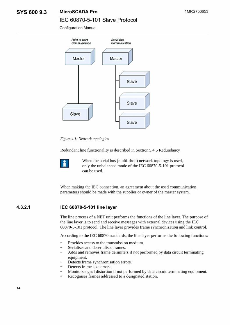
Figure 4.1: Network topologies
Redundant line functionality is described in Section 5.4.5 Redundancy
When the serial bus (multi-drop) network topology is used,only the unbalanced mode of the IEC 60870-5-101 protocolcan be used.
When making the IEC connection, an agreement about the used communicationparameters should be made with the supplier or owner of the master system.
4.3.2.1 IEC 60870-5-101 line layer
The line process of a NET unit performs the functions of the line layer. The purpose ofthe line layer is to send and receive messages with external devices using the IEC60870-5-101 protocol. The line layer provides frame synchronization and link control.
According to the IEC 60870 standards, the line layer performs the following functions:
• Provides access to the transmission medium.• Serialises and deserialises frames.• Adds and removes frame delimiters if not performed by data circuit terminating
equipment.• Detects frame synchronisation errors.• Detects frame size errors.• Monitors signal distortion if not performed by data circuit terminating equipment.• Recognises frames addressed to a designated station.
14
1MRS756653MicroSCADA ProSYS 600 9.3IEC 60870-5-101 Slave ProtocolConfiguration Manual

• Prevents the station transmitting without pause.• Protects messages against loss and errors within predetermined limits.• Reports on persistent transmission errors.• Reports on the status of link configuration.• Supports initiation and maintenance functions.
Line layer attributes
The following attributes can be used for configuring IEC 60870-5-101 master lines inSYS 600.
In UseIU
Indicates whether the line is in use (value 1) or not in use (value 0).
IntegerData type:
0 or 1Value:
1...12 (NET line numbering)Index range:
0Default value:
No limitationsAccess:
ProtocolPO
The data transfer protocol used on the line. The line is defined to the NET by settingthis attribute. By setting the attribute to 0 the line definition including all the line attrib-utes are deleted.
IntegerData type:
0...45Value with IEC 60870-5-101 Slave protocol: 29 (unbalanced mode)or 30 (balanced mode)
Value:
1...12 (NET line numbering)Index range:
Read, conditional writeAccess:
System Device NameSD
Associates the NET line numbers of PC-NET with the device names of the physicalchannels of serial ports.
By default, the line number 1 is connected to the COM1, the line 2 to the COM2 andso on. By using the SD attribute, it is possible to override these default values. Thismay be necessary if the COM ports are used as NET lines or if, for example, a Rocket-Port card is used.
TextData type:
See aboveValue:
1...12 (NET line numbering)Index range:
Read, conditional writeAccess:
15
SYS 600 9.3MicroSCADA Pro
IEC 60870-5-101 Slave Protocol
1MRS756653
31.3.2010Issued:B/30.9.2012Version:
Configuration Manual

Buffer Pool SizePS
Specifies the number of the message buffers reserved for the line. Fixed buffer pollsizes are used in versions 9.3FP1 and newer and this attribute is retained because ofthe backward compatibility. Setting of the value for PS is not possible anymore. Seethe attributes PS, NB and PB from the System Objects manual for more information.
IntegerData type:
1...250Value:
1...12 (NET line numbering)Index range:
Read (conditional write accepted but has no effect)Access:
Baud RateBR
Transmission rate used on the line.
IntegerData type:
1...19200 (384 = 38400 bauds, 576 = 57600 bauds)Value:
Bits / sUnit:
1...12 (NET line numbering)Index range:
9600Default value:
Read, conditional writeAccess:
ParityPY
Specifies the parity check (if any) used for the characters transferred on the line.
IntegerData type:
0 = no parity checkValue:
1 = odd parity
2 = even parity
1...12 (NET line numbering)Index range:
2Default value:
Read, conditional writeAccess:
Receiver Data Bit CountRD
Specifies the number of data bits in each received character.
IntegerData type:
5, 6, 7 or 8Value:
Data bitsUnit:
1...12 (NET line numbering)Index range:
8Default value:
16
1MRS756653MicroSCADA ProSYS 600 9.3IEC 60870-5-101 Slave ProtocolConfiguration Manual

Read, conditional writeAccess:
Stop BitsSB
Specifies the number of stop bits attached to each transmitted character.
IntegerData type:
1 or 2Value:
Stop bitsUnit:
1...12 (NET line numbering)Index range:
1Default value:
Read, conditional writeAccess:
Transmitter Data Bit CountTD
Specifies the number of data bits in each transmitted character.
IntegerData type:
5, 6, 7 or 8Value:
Data bitsUnit:
1...12 (NET line numbering)Index range:
8Default value:
Read, conditional writeAccess:
Polling DelayPD
Delay between polling messages. The purpose of this attribute depends on the commu-nication mode.
In the unbalanced mode this attribute is used only to detect if the master is polling theslave. This watchdog is not used when PD is set to 0. If PD value is larger than 0 andno polls are received between two expirations of the PD timer, the status of the line isreported to be 'not OK'. In practice, this means that the time from line disconnection toreporting is 2 x PD. The status of the line and the stations are reported to be 'not OK'also if the PD value is larger than 0 in the unbalanced mode and the count of the sub-sequent 'Request status of link' message reaches the value defined with line attributeEN. This function can be used to reveal a situation in which the communication lineoperates in one direction only.
In the balanced mode, the link layer of the protocol checks the state of the communica-tion if the time between two consecutive messages is more than the value of the PDattribute.
IntegerData type:
0... 65535Value:
MillisecondsUnit:
17
SYS 600 9.3MicroSCADA Pro
IEC 60870-5-101 Slave Protocol
1MRS756653
31.3.2010Issued:B/30.9.2012Version:
Configuration Manual

1...12 (NET line numbering)Index range:
30000 (unbalanced mode) or 5000 (balanced mode)Default value:
Read, conditional writeAccess:
Transmission Wait DelayTW
Specifies the transmission delay in milliseconds, that is the time that the NET mustwait after receiving a CTS (Clear to Send) signal until starting the transmission of amessage.
IntegerData type:
0...65535Value:
MillisecondsUnit:
1...12 (NET line numbering)Index range:
0Default value:
Read, conditional writeAccess:
CTS DelayDE
Maximum waiting time of the rising edge of the CTS signal after the activation of theRTS signal. Timeout will cause a CTS error and the transmission will not start. A linedisconnection often leads to CTS error.
IntegerData type:
0...65535Value:
MillisecondsUnit:
1...12 (NET line numbering)Index range:
50Default value:
Read, conditional writeAccess:
Header TimeoutHT
Specifies the maximum waiting time in milliseconds within which the first byte of aline layer response from the IEC slave should have been received after the transmissionof a message. If no response has been received within this time, new attempts are per-formed the number of times specified by the Enquiry limit. If no response is still ob-tained, the station will be suspended.
IntegerData type:
0...65535Value:
MillisecondsUnit:
1...12 (NET line numbering)Index range:
2000Default value:
18
1MRS756653MicroSCADA ProSYS 600 9.3IEC 60870-5-101 Slave ProtocolConfiguration Manual

Read, conditional writeAccess:
Response TimeoutTI
The time in seconds that the IEC link waits for the end of the line layer response.
IntegerData type:
0...255Value:
SecondsUnit:
1...12 (NET line numbering)Index range:
2Default value:
No limitationsAccess:
RTS Keep Up Padding CharactersRK
The number of padding characters (null characters) inserted to the end of telegram todelay the passivation of the RTS (Request To Send) signal.
IntegerData type:
0...255Value:
1...12 (NET line numbering)Index range:
0Default value:
Read, conditional writeAccess:
Receive Interrupt Enable DelayRI
Defines the delay in milliseconds after which the receiver of a NET line is enabled aftera message has been issued.
IntegerData type:
0...255Value:
MillisecondsUnit:
1...12 (NET line numbering)Index range:
0 (balanced mode) or 5 (unbalanced mode)Default value:
Read, conditional writeAccess:
Enquiry LimitEN
Specifies the maximum number of times that a message is retransmitted after a timeout.In the unbalanced mode, the attribute specifies the maximum amount of subsequent'Request status of link' messages before the line is reported to be not OK. This functionis active only if the value of the line attribute PD is bigger than 0, see also the corres-ponding attribute description.
IntegerData type:
1...255Value:
19
SYS 600 9.3MicroSCADA Pro
IEC 60870-5-101 Slave Protocol
1MRS756653
31.3.2010Issued:B/30.9.2012Version:
Configuration Manual

1...12 (NET line numbering)Index range:
3Default value:
Read, conditional writeAccess:
Modem SignalSG
An attribute for direct supervision and control of the state of the modem signal. Theattribute applies to all protocols. It is used for diagnostics and testing.
IntegerData type:
0 = Passive signalValue:
1 = active signal
100 * line no + signal no. Signal no. 5 = CTS, 8 = DCD, 20 = DTRIndex range:
Read-onlyAccess:
Message IdentificationMI
Object address of system messages.
IntegerData type:
1...32760Value:
1...12 (NET line numbering)Index range:
6000 + (100 * NET number) + line numberDefault value:
Read, conditional writeAccess:
Message ApplicationMS
The number of the application that is the receiver of the system messages generated bythe line.
IntegerData type:
1...250Value:
1Default value:
1...12 (NET line numbering)Index range:
Read, conditional writeAccess:
Example:
In the example of SYS_BASCON.COM earlier in this chapter, the number of themessage application is 1.
Link TypeLK
The type of data link connection used on the line. This attribute controls the behaviourof the RTS-control line.
IntegerData type:
20
1MRS756653MicroSCADA ProSYS 600 9.3IEC 60870-5-101 Slave ProtocolConfiguration Manual

4: Radio linkValue:
12: Ready to Send (RTS) signal always set, balanced mode
13: RTS/CTS controlling, balanced mode
1...12 (NET line numbering)Index range:
4 (unbalanced mode), 12 (balanced mode)Default value:
Read, conditional writeAccess:
With values 0..10, the behaviour is similar to 4: Radio Link, in which RTS/CTS con-trolling is used and the messages are received in unbalanced fashion. This value shouldbe used in the unbalanced mode. In the balanced mode, the value must be 12 or 13.
Carrier BlockingCB
This attribute determines whether the incoming Carrier Detect (DCD) signal of theserial port must be set in order for the IEC line to receive messages. If Carrier Detectis expected (CB=1),the incoming bytes of the messages are discarded while the DCDsignal is not set. Historically, the Carrier detect was used with modems (e.g. V.23) inorder to indicate the direction of the data flow and filter out corrupted characters whenthe data flow direction changes. A hardware solution is to connect the DCD pin to DTRpin in the RS-232 cable, in this case the messages are always received when th line isin use (IU=1). In versions 9.3FP2 and newer, line attribute CM, bit 2 can be used toachieve the same effect. The usage of line attribute CM is recommended since it issupported by all serial protocols.
IntegerData type:
0 = Carrier blocking not used, messages are received regardless ofthe DCD state
Value:
1 = Carrier blocking used, DCD must be signaled in order to receivemessages
1Default value:
1...12 (NET line numbering)Index range:
Read, conditional writeAccess:
Diagnostic CountersDC
The line protocols gather statistical information about the events on the lines by incre-menting a number of diagnostic counters. All the major events and error situations ofthe communication have their own counters.
When accessing diagnostic counters, the attribute is indexed according to the formula:100 * (line number) + (diagnostic counter number)
The IEC 60870-5-101 Slave protocol supports the following counters:
1. Transmitted telegrams
21
SYS 600 9.3MicroSCADA Pro
IEC 60870-5-101 Slave Protocol
1MRS756653
31.3.2010Issued:B/30.9.2012Version:
Configuration Manual

2. Failed transmissions
4. Transmitted commands
5. Transmitted replies
11. Received messages
12. Parity errors
13. Overrun errors
14. Check sum errors
15. Framing errors
16. Buffer overflow errors
IntegerData type:
0...30000Value:
See aboveIndex range:
Read-only, the values can be resetAccess:
Operating ModeOM
This attribute consists of a set of flags which control the behaviour and functionalityof the IEC line. Each flag is one bit of this attribute. The bits are the following:
IntegerData type:
0..65535Value:
1...12 (NET line numbering)Index range:
0Default value:
Read, conditional write (No limitations in balanced mode)Access:
Balanced mode handshakeWhen this bit is 0, the sending of the handshaking messages (request,status of link, reset of remote link) are NOT restarted when a ‘requeststatus of link’ message is received from the remote end.
Bit 0:
When the bit is 1, the sending of the handshaking messages are restar-ted when a ‘request status of link’ message is received. Notice, thatif SYS 600 is used in both ends, only one of them should have thisbit set. This bit is meaningful only in the balanced modes.
22
1MRS756653MicroSCADA ProSYS 600 9.3IEC 60870-5-101 Slave ProtocolConfiguration Manual
Redundant line behaviour in balanced modeWhen the bit is 0, the redundant line behaves as described in thedocument “Norwegian User Conventions for IEC60870-5-101”.When the bit is 1, the redundant line behaves as described in thedocument “Norwegian User Conventions for IEC 60870-5-101”, ex-cept an ACK (FUNC=0) response is given instead of a NACK(Func=1) response when the master issues a ‘test function for link’request. In balanced mode, an automatic line switch is made, whenthe master issues a command to the backup line. Bit 1 is meaningfulin balanced mode only.
Bit 1:
Link initialization in both directions requiredWhen this bit is 0, the data messages are accepted before the link hasbeen initialized completely in both directions. This is the default mode.When this bit is 1, the data messages are not accepted until the com-munication link has been initialized in both primary and secondarydirections. In this mode, in case of a received 'request status of link'message or a primary link reset due to timeouts, it is assumed that thesecondary link is not initialized anymore. Bit 5 is meaningful in bal-anced mode only.
Bit 5:
4.3.2.2 IEC 60870-5-101 station object
The main purpose of the station layer is the protocol conversion between the IEC60870-5-101 and the internal protocol of SYS 600. The station objects also takes careof the application level communication with the master.
The STA objects created in a NET unit perform the functions of the station object. SeveralSTA objects of the type IEC devices are allowed on the same line. It is also possible thatmultiple station shares the same remote IP-address.
The STA objects created in a NET unit perform the functions of the station object. Someattributes are used for the station configuration, others are used for device communication.The configuration attributes are presented in this chapter and the communication attributesin the next one.
Station attributes
The following attributes can be used for configuring the IEC 60870-5-101 Slave stationsin SYS 600.
In UseIU
Indicates whether the station is in use (value 1) or not in use (value 0).
IntegerData type:
0 or 1Value:
0Default value:
23
SYS 600 9.3MicroSCADA Pro
IEC 60870-5-101 Slave Protocol
1MRS756653
31.3.2010Issued:B/30.9.2012Version:
Configuration Manual

No limitationsAccess:
Line NumberLI
The number of the NET line the station is connected to. This attribute is also used forsetting the number of the back-up line, if redundant IEC lines are used. Note that indexes1 and 2, i.e. the main and back-up line numbers, are switched when a line switch oper-ation is executed.
IntegerData type:
1...12 (NET line numbering)Value:
None if redundant lines are not usedIndex 1 is for the number of the main lineIndex 2 is for the number of the back-up line
Indexing:
Read, conditional writeAccess:
Polling AddressPA
The link address of the IEC 60870-5-101 Slave station.
IntegerData type:
0...254, when PL attribute = 1Value:
0…65535, when PL attribute = 2
Address 255 is reserved for broadcast mes-sages (PL=1).
Address 65535 is reserved for broadcastmessages (PL=2).
1Default value:
Read, conditional writeAccess:
Note that if the configuration contains multiple stationsconnected to the same line (LRU configuration), they willshare the common polling address. If different link address isrequired, an individual line and COM-port must be used foreach station and the combination of these lines must be solvedwith hardware.
Station AddressSA
The station address of the IEC 60870-5-101 Slave station, the common address ofASDU in an IEC message.
24
1MRS756653MicroSCADA ProSYS 600 9.3IEC 60870-5-101 Slave ProtocolConfiguration Manual

IntegerData type:
0...255, when SL attribute = 10...65535, when SL attribute = 20…16777215, when SL attribute = 3
Value:
1Default value:
Read, conditional writeAccess:
Polling Address LengthPL
The length of the link address in octets.
IntegerData type:
1 or 2Value:
1Default value:
Read, conditional write (line IU must also be 0 when writing)Access:
Station Address LengthSL
The length of the station address (common address of ASDU) in octets.
IntegerData type:
1 or 2Value:
1Default value:
No limitationsAccess:
Information Address LengthIL
The length of the information object address in octets.
IntegerData type:
1...3Value:
2Default value:
Read, conditional writeAccess:
Length of Cause of Transmission InformationCL
The length of the cause of transmission field in an IEC 60870-5-101 message in octets.If the originator addresses are used, the value of this attribute should be set to 2.
IntegerData type:
1 or 2Value:
1Default value:
No limitationsAccess:
AllocationAL
25
SYS 600 9.3MicroSCADA Pro
IEC 60870-5-101 Slave Protocol
1MRS756653
31.3.2010Issued:B/30.9.2012Version:
Configuration Manual

Allocates the station to an application. When the AL attribute has the value 1, the stationis reserved by the application specified by the AS attribute. All the spontaneous messagesfrom the station are sent to this application.
IntegerData type:
0 or 1Value:
No limitationsAccess:
Allocating ApplicationAS
Specifies the allocating application of the station (see the AL attribute). The allocatingapplication will get all the spontaneous process data from the station. This applicationis also the only one that is allowed to set the device communication attributes
IntegerData type:
0...250,0 = no application
Value:
Read-only , conditional writeAccess:
When the AL attribute is set to 0, AS also gets the value 0.
Message IdentificationMI
Object address of system messages.
IntegerData type:
1...32760Value:
29000 + station numberDefault value:
No limitationsAccess:
Message ApplicationMS
The number of the application, that is the receiver of the system messages generatedby the line.
IntegerData type:
1...250Value:
1Default value:
No limitationsAccess:
System Messages EnabledSE
Specifies whether the system messages generated by the NET and related to the stationare sent to applications (value 1) or not (value 0). By using this attribute, it is possibleto disable the system messages related to the station.
26
1MRS756653MicroSCADA ProSYS 600 9.3IEC 60870-5-101 Slave ProtocolConfiguration Manual

IntegerData type:
0 or 1Value:
1Default value:
No limitationsAccess:
Command AddressCA
The object address of bit stream process object in the SYS 600 process database, whereunidentified messages are sent.
IntegerData type:
1 … 65535Value:
32000Default value:
No limitationsAccess:
The unit number (UN attribute) of the bit stream process objectmust be the same as the STA object number.
Command DelayCD
The Command Delay attribute specifies the maximum delay for timestamped commands.If the timestamp of the incoming command message indicates that the transmissiondelay has been bigger than the value defined with this attribute, the command is notaccepted. The attribute defines a time window in which the timestamped command isaccepted.
IEC Station attribute CC controls how the “summer time” bit of the incoming commandis handled. See the corresponding description for more information.
The value of the NET node attribute TZ (Time zone) is used to compensate thetimestamps of different time zone.
The timestamped control commands are normally used only in IEC60870-5-104 andnot in IEC60870-5-101.
0...65535Value:
MillisecondsUnit:
1000Default:
Read/WriteAccess:
Example
If STA1:SCD is 2000, only the command with timestamps +-2000 ms around the currenttime of the slave computer is accepted.
Maximum Message LengthML
27
SYS 600 9.3MicroSCADA Pro
IEC 60870-5-101 Slave Protocol
1MRS756653
31.3.2010Issued:B/30.9.2012Version:
Configuration Manual

The maximum amount of octets containing information objects. The link header includ-ing link address and The Application Protocol Control Information (APCI) fields andData Unit Identifier fields are excluded from this value. This attribute is automaticallyset to a smaller value if the total message length would exceed 253 bytes with the givenvalue.
IntegerData type:
20...255Value:
253Default value:
Single Char ResponseSR
Enables or disables single char responses. If single char responses are enabled, thestation object replies with a 0xE5 character as a link layer acknowledgement. If singlechar responses are enabled in unbalanced mode, 0xE5 character is also replied insteadof a “requested data not available” message to a poll.
IntegerData type:
0 or 1Value:
0 (single char responses disabled)Default value:
Read, conditional writeAccess:
Event buffer overflow AddressEA
Defines the information object address of the single indication, which is used to indicatethe event buffer overflow situation. See the descriptions of:
With index 2 it possible to define a percentage of the buffer space. If value differentfrom 100 is defined, single indication indicating the event buffer overflow is resent notuntil the event buffer space has gone below the defined level of the total space at leastonce.
See example below.
See the descriptions of:
• Bit 6 of the RM attribute• PRI parameter of the EV attribute
IntegerValue:
Index 1 or no index: 0..16777215
Index 2: 0..100
1..2 or no indexIndexing:
Index 1 or no index : Information object address
Index 2 : Percentage of buffer space
Index 1 or no index:32001, Index 2 = 100 (Percentage limit not used)Default value:
Read/WriteAccess:
28
1MRS756653MicroSCADA ProSYS 600 9.3IEC 60870-5-101 Slave ProtocolConfiguration Manual

Example 1.
STA1:SEA1=65535 ; Event buffer overflow event is sent to address65535
STA1:SEA2=80
When event buffer overflow event has been sent, the same event is sent again not untilthe total amount of events has gone under or equal to 80% of the total event bufferingspace.
eXecute TimeoutXT
The maximum time an execute command is waited after a select command. The valueis meaningful only if the bit 4 of the RM attribute is not set. See the RM attribute de-scription for further information.
IntegerData type:
0... 65Value:
SecondsUnit:
30Default:
No limitationsAccess:
ConFirmation ModeCF
The waiting of the activation termination message. With value 0, the timer defined withthe CT attribute is not started. Value 0 is needed with some IEC 60870-5-101 Slaveimplementations, which do not send activation termination messages at all.
IntegerData type:
0 = Activation termination is not waitedValue:
1 = Activation termination is waited
1Default value:
No limitationsAccess:
Process Data ConfirmationPC
Controls how the confirmation message is sent to the master station. The manual con-firmation (value 0) means that the user has to confirm the incoming message from SCILby setting the CF attribute. The automatic confirmation (value 1) means that the con-firmation is done automatically by NET once the base system accepts the data messagesent by NET. System and Application commands are not confirmed automatically ifthe attribute is set to the automatic test mode.
IntegerData type:
0, 1Value:
0Default value:
Read, conditional writeAccess:
29
SYS 600 9.3MicroSCADA Pro
IEC 60870-5-101 Slave Protocol
1MRS756653
31.3.2010Issued:B/30.9.2012Version:
Configuration Manual

Time SynchronizationTC
Determines the behaviour of the slave device when it receives a time synchronizationmessage as follows:
IntegerData type:
0...3Value:
0 = The synchronization message is handled and the clock of the basesystem is set to the received time. The synchronisation message is notsent to the process database.
Value 1 = The clock of the base system is set to the received time andthe synchronisation message is also sent to the process database (toa bit stream process object with address as defined by the CA attrib-ute).
Value 2 = The clock of the base system is not set, but the synchronisa-tion message is sent to the process database.
Value 3 = Synchronisation messages are not handled at all.
1Default value:
No limitationsAccess:
Invalid TimeIV
The "invalid time" information in timestamped messages will follow the value of thisattribute. When a time synchronization is received from IEC60870-5-101/IEC60870-5-104 line, this attribute is set to value 0 and the timestamped messages are transmittedwith valid time. If the application writes value 1 to this attribute, the timestampedmessages are transmitted with invalid time. If value 0 is written, messages will betransmitted with valid time. This attribute is useful if e.g. the connection to GPS makingthe synchronization is lost. If IV attribute is not written from application, "invalid time"bit behaves as described in RM attribute bit 1.
IntegerData type:
0 or 1Value:
NoIndexing:
No limitationsAccess:
Running ModeRM
Consists of a set of flags that control the behaviour and functionality of the IEC Slavestation. Each flag is one bit of this attribute. The bits are as follows:
30
1MRS756653MicroSCADA ProSYS 600 9.3IEC 60870-5-101 Slave ProtocolConfiguration Manual

The hour transmission method of the events from the slave station.When this bit is 0, the slave device sends a spontaneous clock syn-chronisation message (ASDU 103) to the master whenever the hourchanges. When this bit is 1, the synchronisation message is not sentand the master can add its own time to events.
Bit 0:
Time synchronisation method. When this bit is 0, the slave stationwaits for a synchronisation command from the master station andmarks the time stamps as invalid until the synchronisation commandis received. When this bit is 1, the synchronisation message is notexpected and the time stamps are not marked as invalid.
Bit 1:
Confirmation queue (significant only in the unbalanced mode). Whenthis bit is 0, all the confirmation messages are put to class 1 queue.When this bit is 1, confirmation messages are put to class 2 queue.
Bit 2:
Handling of unrecognised commands. When this bit is 0, unrecognisedcommand messages are ignored. When this bit is 1, unrecognisedcommand messages sent by the master are forwarded to a bit streamprocess object with an address as defined by the CA attribute.
Bit 3:
Select-execute timeout enable/disable. When this bit is 0, the validityof each select and execute command for ‘single command’ or ‘doublecommand’ types is checked. A negative confirmation is automaticallyreturned if:
Bit 4:
• the execute command is received without a preceding selectcommand
• the object address, ASDU type or value is not equal to the pre-cending select command
• another select command is received (except for matching deactiv-ation which is accepted)
The length of the timeout is defined with the XT attribute. As men-tioned, this checking applies to ‘single command’ or ‘double com-mand’ASDUs only. Up to 10 select commands may be pending atthe same time. When the bit is 1, the commands are not checked andthe process objects are always updated. The value of XT is meaning-less in this case.
SQ=1 packing enabled/disabled. When this bit is 1, data of ASDUs1,3,9,11,13 is packed in SQ=1 style. The usage of this packing stylemay speed up the communication, if the addresses entered in ComToolcontain blocks. In these blocks the addresses are incremented sequen-tially. This means that addresses like baseaddr, baseaddr+1 or basead-dr+2 are used.The SQ=1 packing is not supported for time taggeddata. When this bit is 0, SQ=1 packing is not used and the packing ismade in standard SQ=0 packing style.
Bit 5:
31
SYS 600 9.3MicroSCADA Pro
IEC 60870-5-101 Slave Protocol
1MRS756653
31.3.2010Issued:B/30.9.2012Version:
Configuration Manual

If this bit is 1 and error 13856 ICCC_ASDU_QUEUE_FULL is re-turned during writing to the EV attribute, the included timestamp isstored. A single indication message using this timestamp is transmittedautomatically as the first event message when communication to themaster proceeds. The information object address of the event is definedwith the EA station attribute. Using attribute EA, index 2 it is possibledefine a percentage level which limits the resending of this eventoverflow indication. If this bit is 0, no action is taken when error isreturned.
Bit 6:
When this bit 0, the parameter ASDU types 110-112 (P_ME_NA_1,P_ME_NB_1 and P_ME_NC_1) received from the master update abitstream process object defined with application layer attribute CA.When this bit is 1, the the incoming parameter ASDU types 110-112are handled similarly to set-point command ASDUs 48-50 or ASDUs61-63 i.e. an analog input process object is updated.
Bit 7:
Exceptional command checking. If this bit is 1 and an exceptionalcommand is received, an immediate response with cause of transmis-sion 44..47 (unknown type identification, unknown cause of transmis-sion, unknown common address of ASDU or unknown informationobject address) is sent back to the master. If this bit is 0, the cause oftransmission of the response is defined in the MicroSCADA applica-tion.
Bit 8:
IntegerData type:
0...65535, see aboveValue:
0Default value:
Read, conditional writeAccess:
Diagnostic CountersDC
The values of the diagnostic counters which the NET unit keeps for the station. Thecounters have the following meaning:
32
1MRS756653MicroSCADA ProSYS 600 9.3IEC 60870-5-101 Slave ProtocolConfiguration Manual

1. Suspension information (0 = OK, 1 = suspended)
2. Suspension counter
3. Transmitted data messages
4. Transmitted command messages
5. Transmitted confirmation messages
6. Received data messages
7. Received command messages
8. Received confirmation messages
9. Received unknown messages
10. Received too long messages
15. Application response timeouts
IntegerData type:
1...65535Value:
1...20Index range:
No limitationsAccess:
Object StatusOS
The current status of the IEC station object. When value 1 is written to this attribute,the station object retransmits its current status codeto the system message process object.
IntegerData type:
when Read, 0 = OK_STATUS ornon-zero value = communication is not normal at the moment
Value:
No limitations (write is possible only with value 1)Access:
Queue InformationQI
Information from the class queues. Returns the amount of unsent ASDUs with matchingvalues for COT (Cause Of Transmission) or TYPE ID (Type Identification).
When accessed, the formula for indices is
100*OPERATION+FIRST..100*OPERATION+LAST
The different values of OPERATION:
33
SYS 600 9.3MicroSCADA Pro
IEC 60870-5-101 Slave Protocol
1MRS756653
31.3.2010Issued:B/30.9.2012Version:
Configuration Manual

1 : class 1 ASDUs in which COT is in range FIRST..LASTOPERATION =
2 : class 2 ASDUs in which COT is in range FIRST..LAST
3 : class 1 + class 2 ASDUs in which COT is in range FIRST..LAST
4 : class 1 ASDUs in which TYPE_ID is in range FIRST..LAST
5 : class 2 ASDUs in which TYPE_ID is in range FIRST..LAST
6 : class 1 + class 2 ASDUs in which TYPE_ID is in rangeFIRST..LAST
IntegerData type:
0...255Value:
1...6 (see above)Index:
The last index is optional (see above).
Read-OnlyAccess:
Examples
STAx:SQI103 ;Returns the amount of unsent ASDUs from class 1 withCOT=3
;(Spontaneous)
STAx:SQI(320..336) ;Returns the amount of unsent ASDUs withCOT=20..36
;(Interrogated/Group interrogated)
STAx:SQI513 ;Returns the amount of unsent ASDUs from class 2 withTYPE
;ID=13 (M_ME_NC_1)
STAX:SQI(699..701) ;Returns the amount of unsent ASDUs from withTYPE
;ID=99..101 (Interrogation commands)
SYS Waiting TimeST
The maximum time that the slave station waits for a reply from the base system.
IntegerData type:
0...60000Value:
MillisecondsUnit:
5000Default value:
No limitationsAccess:
Maximum Delayed Response TimeMT
The maximum time to delay response for writing data to the SD and EV attributes, ifthe number of items in the queue is greater than the value of the RW attribute.
34
1MRS756653MicroSCADA ProSYS 600 9.3IEC 60870-5-101 Slave ProtocolConfiguration Manual
IntegerData type:
0...600Value:
0 = Delayed response mechanism not used
SecondsUnit:
0Default value:
No limitationsAccess:
A high value of this attribute may cause queuing of commandprocedure executions in the base system during communicationdisturbance.
Command ControlCC
This attribute defines how the incoming timestamped control commands and timesynchronization commands are handled.
See NET node attribute TZ (Time Zone) and IEC station object attribute CD (Commanddelay) for more information.
The term 'summer time' is used in IEC standards as is a synonym for 'daylight savingtime'.
The timestamped control commands are normally used only in IEC60870-5-104 andnot in IEC60870-5-101.
Values of the 'summer time' bit are:
0 = standard time
1= summer time/daylight saving time
IntegerData type:
0Default:
0... 1Value:
Value 0 = The 'summer time' bit of the timestamp in the incomingcommand is ignored. The timestamp of the incoming command iscorrected with the value of the NET node attribute TZ (Time zone).In order to accept the incoming command, the difference between thistimestamp and the arrival time (from local clock) of message mustnot be bigger than the time window defined with station attribute CD.
35
SYS 600 9.3MicroSCADA Pro
IEC 60870-5-101 Slave Protocol
1MRS756653
31.3.2010Issued:B/30.9.2012Version:
Configuration Manual

Value 1 = The 'summer time' bit of the timestamp in the incomingcommand is expected to contain a correct value. It is taken into accountin the clock setting or in the time comparison with the arrival time.The value of the TZ is also taken into account, which means that ifthe timestamp of the incoming command is in UTC time, the TZ at-tribute of the NET node value should contain the amount of minutesbetween the local time zone in winter time and the UTC time.
If the value of the 'summer time' bit is different from the daylight saving time informationof the local clock, the 1-hour difference is compensated before clock setting or thecomparison to the arrival time. In order to accept the control command, the differencemust not be bigger than the time window defined with station attribute CD.
Summer TimeSU
States whether summer time is used or not. With this attribute the user can change theSU flag in the IEC time tag. The SU attribute can be used for example to tell a mastersystem that the time tagged event uses summer time. If the master system does not usesummer time, it is then able to change the time to its own time.
IntegerData type:
0 or 1Value:
0 (summertime not used)Default value:
No limitationsAccess:
Reply Window SizeRW
Defines how many data items (binary values, analog values) can be written from thebase system to NET without a reply or request from the master. If the slave stationcannot send data items spontaneously to the master, it stores data into local buffers andcreates a local reply to the base system and the execution of the SCIL program cancontinue. The slave station stores items until the number of items in local buffers isequal to RW. After that the slave station delays the replies to the base system until thenumber of items drops below RW again (data sent to master and reply received). Thisdelay is configurable and it is defined by the MT attribute.
IntegerData type:
0…10000Value:
10Default value:
No limitationsAccess:
4.3.2.3 Redundant line attributes
SYS 600 provides support for redundant IEC 60870-5-101 Slave lines. This means thatone IEC slave station can have two lines. One of them is the main line, initially meantto be the primary communication channel. The other line is the back-up line, meant to
36
1MRS756653MicroSCADA ProSYS 600 9.3IEC 60870-5-101 Slave ProtocolConfiguration Manual

serve as a secondary communication channel in case the main line fails. If acommunication disturbance is detected, the communication can be switched from themain line to the back-up line and vice versa without losing any messages to be sent tothe master. A line switch is initiated by the master.
The main line and the back-up line can have different communication parameters, e.g.baud rate. In addition to this, both of the lines can have dial-up configured.
When a redundant IEC 60870-5-101 Slave connection is configured, the following stepsshould be taken:
1. Define the main line.2. Define the back-up line.3. Define the station.
The following line attribute is used with redundant IEC 60780-5-101 lines:
Redundant Line StationRU
This attribute defines the number of the STA object connected to redundant IEC lines.This attribute should be set both for the main and back-up lines. The informationprovided by this attribute is needed when a line switch operation is executed. Value 0indicates that redundant lines are not used.
IntegerData type:
0...255Value:
1...12 (NET line numbering)Index range:
0Default value:
Read, conditional writeAccess:
The following station attribute is used with redundant IEC 60780-5-101 lines:
Line NumberLI
The number of the back-up line is set to index 2 of the LI attribute. Refer to the LI at-tribute presented earlier in the Section 4.3.2.1 IEC 60870-5-101 line layer.
Example:
#SET STA1:SLI(2) = 5
When using redundant IEC 60870-5-101 lines, the IEC master must provide thecorresponding functionality. The implementation of the line switch mechanism isdescribed in Section 5.4.5 Redundancy of this document.
The backup line must be defined with the LI attribute rightafter station has been created.
37
SYS 600 9.3MicroSCADA Pro
IEC 60870-5-101 Slave Protocol
1MRS756653
31.3.2010Issued:B/30.9.2012Version:
Configuration Manual

There can be only one IEC station for a pair of redundant lines.
When using redundant IEC 60870-5-101 lines, the ASDUnumber 128 is used for communication line activation and theASDU M_SR_NA_1 Parameter Byte String cannot be used.
4.3.2.4 Autodialling attributes
SYS 600 provides support for the Autocaller functionality for the IEC 60870-5-101 Slaveprotocol. An Autocaller is a modem with functions for automatic dial-up. The dial-upcan be initiated by the IECmaster or the IECslave.
The Autocaller must use the AT (Hayes) command set. Note that when using odd oreven parity, the modem must support 11-bit word length. In some cases, this featuremust be enabled by using the AT commands. Refer to the documentation of the modemin use for further details.
The following Autocaller attributes are valid for the IEC 60870-5-101 Slave lines:
Autocaller EnabledAC
The AC attribute states whether an Autocaller is connected to the line (value 1) or not(value 0).
IntegerData type:
0 or 1Value:
0Default value:
No limitationsAccess:
Autocaller StateAS
This attribute indicates the state of the Autocaller.
IntegerData type:
0...4Value:
0 = IDLE, ready to make a call
1 = CONNECTED, transmission is activated
2 = BUSY, Autocaller is dialling
3 = INITIAL, Autocaller is uninitialized
4 = CONFIGURE, the IU attribute of the line is set to 0
0Default value:
Read-onlyAccess:
38
1MRS756653MicroSCADA ProSYS 600 9.3IEC 60870-5-101 Slave ProtocolConfiguration Manual

Connection Time LimitedCL
This attribute determines whether a time limit has been set to the connection (value 1)or not (value 0). The maximum duration of the connection is determined by the CT at-tribute.
IntegerData type:
0 = no time limitValue:
1 = time limit
1Default value:
Suggested value: A time limit is necessary on certain radio telephone lines. Limitingthe connection time may be good practice also in other cases, if there is a risk that theconnection is not otherwise broken.
No limitationsAccess:
Connection TimeCT
The maximum time that a connection is allowed to last (in seconds). This attribute issignificant only if time limiting is activated (CL = 1).
IntegerData type:
0...600Value:
SecondsUnit:
120Default value:
No limitationsAccess:
ConnectionCN
The CN attribute is used for dialling devices from the NET and for breaking telephoneconnections. This attribute has significance only in the unbalanced mode.
A call to a station or workplace is initiated by writing the phone number to the CN at-tribute. The NET unit then commands the autodialling modem to dial the number. Thesuccess of the dialling is reported as a system message. Writing an empty string to CNbreaks the connection.
TextData type:
Text string of maximum 25 charactersValue:
Empty text stringDefault value:
No limitationsAccess:
Example:
#SET NET1:SCN5 = "123456789S11"
Connected StationCS
39
SYS 600 9.3MicroSCADA Pro
IEC 60870-5-101 Slave Protocol
1MRS756653
31.3.2010Issued:B/30.9.2012Version:
Configuration Manual

The link address of the station a NET unit is communicating with.
IntegerData type:
0...65535Value:
0 = Autocaller not defined or no communication
0Default value:
Read-onlyAccess:
Radio Disconnection DelayDD
Delay between the last data transfer and line disconnection.
IntegerData type:
0...32767Value:
SecondsUnit:
0Default value:
No limitationsAccess:
Modem CommandMC
Using this attribute, a modem can be controlled directly from SCIL with the AT/Hayescommands. When an AT command is written to the MC attribute, it is transmitted tothe modem on the line. The response from the modem is read using the same attribute.
TextData type:
Text string, an AT/Hayes commandValue:
0Default value:
No limitationsAccess:
Example:
#SET NET1:SMC3 = ("AS0?")'
Pulse DialingPU
This attribute determines the dialing principle used.
IntegerData type:
0 = tone dialingValue:
1 = pulse dialing
0Default value:
No limitationsAccess:
Remote Calls EnabledRC
40
1MRS756653MicroSCADA ProSYS 600 9.3IEC 60870-5-101 Slave ProtocolConfiguration Manual

The RC attribute states whether remote calls are enabled on a line, that is if the NETunit can be called from the stations connected to the line in question. The attribute appliesto lines with autocaller (AC = 1).
IntegerData type:
0 = remote calls not enabledValue:
1 = remote calls enabled
0Default value:
No limitationsAccess:
Radio Connection Wait TimeRW
Normally, the DCD (Data Carrier Detect) signal is used to indicate an active connection.However, there are cases where this is not possible, for example on radiotelephonelines using half-duplex links. The RW attribute defines the waiting time in seconds insuch a situation: from the finishing of the dialling until the transmission is started.
IntegerData type:
0...32767Value:
SecondsUnit:
0Default value:
No limitationsAccess:
Autocaller AT S RegisterSR
The S registers used by the Autocallers follow the AT (Hayes) de facto standard.
All the Autocallers which use the AT command set have a number of S registers. Thenumber of registers used and the meaning of the individual registers slightly variesfrom one Autocaller model to another. The contents of the S registers are therefore notdescribed in this document. Refer to the modem manuals.
Using the SR attribute, the S registers number 2, 6, 7, 8, 9, 10, 11 and 12 are accessed.By using the MC attribute (see above), other S registers can also be accessed. The Sregisters 11 and 12 cannot be set.
IntegerData type:
See the modem manualsValue:
SecondsIndexing:
100 * line number + register numberAccess:
Example:
The S register number 6 of line 2 in NET1 is set = 4:
#SET NET1:SSR206 = 4
41
SYS 600 9.3MicroSCADA Pro
IEC 60870-5-101 Slave Protocol
1MRS756653
31.3.2010Issued:B/30.9.2012Version:
Configuration Manual

4.3.2.5 File transfer attributes
The IEC file transfer feature transmits all types of files between relay and the SYS 600computer. Only one transmission per one STA object can be active at the same time. Ifthe another file transfer request is made during the first file transfer is in progress, thestatus code is returned and the second file transfer progress does not start.
File InformationFI
The FI attribute initializes the file transfer system with needed base information.
Vector of 5 integersValue:
1 = internally used
2 = SEGMENTCOUNT
3 = internally used
4 = QUEUE (unbalanced slave)
5 = PRIORITY (slave)
6 = Section request delay IN (0.1 seconds)
7 = Section filling delay OUT (0.1 seconds)
1..7Indexing:
Read/WriteAccess:
1 = 0Default value:
2 = 8
3 = 0
4 = 2
5 = 3 (1 is lowest value)
6 = 0 (0 milliseconds)
7 = 10 (1000 milliseconds)
Example:
The following example defines five segments in the each file section.
#SET STA'sta':SFI(2)=5
File DirectoryFD
The FD attribute defines to which directory the received files are stored. PC_NET in-terrupts file receiving, if the directory does not exist or if it is write-protected.
42
1MRS756653MicroSCADA ProSYS 600 9.3IEC 60870-5-101 Slave ProtocolConfiguration Manual

String contains a valid directory name with maximum length of 50characters.
Value:
Read/WriteAccess:
C:\TEMPDefault:
Example:
The following example defines C:\SC\DATA to the active directory.
#SET STA'sta':SFD="C:\SC\DATA"
File Transmission StatusFF
The FF attribute indicates the status of the file transmission.
0 = Free to start or the previous transmission is completedValue:
1 = Transmit in progress
2 = Timeout in PC_NET
3 = Not used
4 = Invalid directory or file name
5 = File is not available in the remote end
6 = Service is not available, internal error
7 = Transfer aborted
8 = File reading or writing failed
Read, Write is allowed when the value is not 6.Access:
0Default value:
If transmission is in progress when the FF attribute is written, the transmission isaborted and the file is closed. It does not have any other effects, except the value is setto zero (0).
File TimeoutFT
The FT attribute defines the maximum delay for incoming ack section or ack file request.If the time expires, PC_NET interrupts the file transmission.
0..255Value:
SecondsUnit:
Read/WriteAccess:
30 secondsDefault value:
File BytesFB
43
SYS 600 9.3MicroSCADA Pro
IEC 60870-5-101 Slave Protocol
1MRS756653
31.3.2010Issued:B/30.9.2012Version:
Configuration Manual

The FB attribute returns both counts of received or transmitted bytes from the beginningof the file transfer session (index 1) and the file size (index 2). At the beginning of thefile reception, the value of index 1 is automatically set to zero (0). The value of index2 is updated when the FB attribute is written and a correct file index is given.
0..4294967295Value:
When readIndexing:
1 = Number of bytes (DWORD), out
2 = File size in bytes (DWORD), out
3 = File name in relay (DWORD), out
4 = Number of bytes (DWORD), in
5 = File size in bytes (DWORD), in
6 = File name in relay (DWORD), in
ReadAccess:
0Default:
File NameFN
The FN attribute collects the information address to certain file in the file system. Whenthe remote end requests the directory, the information address is reported as a real file,not as a subdirectory (FOR = 0).
When writtenValue:
IOA
NAMEOFFILE
FILETYPE
STATUSOFFILE
NAMEINFILESYSTEM
SIZEINFILESYSTEM
DATEINFILESYSTEM
MSECSINFILESYSTEM
When read
NAMEINFILESYSTEM
When read
44
1MRS756653MicroSCADA ProSYS 600 9.3IEC 60870-5-101 Slave ProtocolConfiguration Manual

When read, (0..299)Indexing:
Queue out: index = 100+FILENUM
Queue in: index = 200+FILENUM
If the FILENUM offset is bigger than the number of files in the list, status code 13887ICCC_NO_SUCH_FILE is returned.
For more information about status codes, see Section 5.8 Status codes
Read/writeAccess:
Where when writing
IOAInformation object address.Type: DWORD
NAMEOFFILEDefines the name of file field in the file transfer messages.Type: WORD
FILETYPEType: WORDValues: 1 = Transparent fileOther types are not supported at the moment.
STATUSOFFILEType: BYTEValues: 0 = File waits for transfer
NAMEINFILESYSTEMString contains a valid file name in the disk with maximum length of 100 charaters. Ifthe string is empty, the file is deleted from the list.
SIZEINFILESYSTEM (optional)The file size.Type: DWORD
DATEINFILESYSTEM (optional)Creates file’s timestamp (seconds from 1.1.78).Type: TIME
MSECSINFILESYSTEM (optional)Creates file’s timestamp (milliseconds).Type: WORD
Example of writing
#SET STA'sta':SFN=(1000, 1,1,0, "error.log", 5000, %clock)
Example of reading
45
SYS 600 9.3MicroSCADA Pro
IEC 60870-5-101 Slave Protocol
1MRS756653
31.3.2010Issued:B/30.9.2012Version:
Configuration Manual

The second file is read from the outgoing file list and returns the error.log file.
STA'sta':SFN(102)
File ValuesFV
The FV attribute checks the status of the defined file. During the reading process, theattribute’s index defines where the file value is taken, either from the outgoing files listor from the incoming files list.
VectorValue:
IOA
NAMEOFFILE
FILETYPE
CTRLANDSTATUSOFFILE
SIZEINFILESYSTEM
DATEINFILESYSTEM
MSECSINFILESYSTEM
When read, word (0..65535)Indexing:
Queue out: index = 100+FILENUM
Queue in: index = 200+FILENUM
If the FILENUM offset is bigger than the number of files in the list,status code 13887 ICCC_NO_SUCH_FILE is returned.
For more information about status codes, see Section 5.8 Status codes
46
1MRS756653MicroSCADA ProSYS 600 9.3IEC 60870-5-101 Slave ProtocolConfiguration Manual

Read, WhereAccess:
IOAInformation object address
NAMEOFFILEDefines the name of file field in the file transfer messages.Type: WORDIf value = 0 is given for both IOA and NAMEOFFILE, a unique valueis assigned.
FILETYPE
Type: WORDValues: 1 = Transparent fileOther types are not supported at the moment.
CTRLANDSTATUSOFFILE
Type: WORD.The upper byte is a control byte.
Bit 0 : Internally used
Bit 1=0: Not yet transmitted
Bit 1=1: All sections transmitted
Bit 2=0: Transmission not acked by remote
Bit 2=1: Transmission acked by remote
The lower byte is equal to status of file (SOF)
Bit 7=0: File waits for transfer (FA)
Bit 7=1 Transfer of this file is active (FA)
SIZEINFILESYSTEM
Type: DWORD
The file size.
DATEINFILESYSTEM
Type: TIME
Creates file’s timestamp.
Example
Reading the second file from the outgoing file list.
47
SYS 600 9.3MicroSCADA Pro
IEC 60870-5-101 Slave Protocol
1MRS756653
31.3.2010Issued:B/30.9.2012Version:
Configuration Manual

STA'sta':SFV(102)
3 ;Information object address
3 ;Name of file
1 ;Transparent file
1536 ;CTRL=(transmitted, acked), SOF=0
10006 ;Filesize=10006 bytes
847636153 ;Timestamp
If the FILENUM offset is bigger than the number of files in the list, status code 13887ICCC_NO_SUCH_FILE is returned.
For more information about status codes, see Chapter 5.8 Status codes
Send SubdirectorySS
The SS attribute initiates the transmission of the directory listing from the specifiedaddress.
IOA, (COT) vectorValue:
Write, WhereAccess:
IOA
Type: DWORD
Is not in use at the moment
COT (optional)
Type: BYTE
Defines the cause of transmission.
If the value is not given, value three (3) is used.
Example
The following example initiates the file directory’s transmission by using cause oftransmission 3.
#SET STA'sta':SSS=(1,3)
More examples on communication system configuration, see Appendix A Examples ofcommunication system configuration
48
1MRS756653MicroSCADA ProSYS 600 9.3IEC 60870-5-101 Slave ProtocolConfiguration Manual

4.4 After configuration
For each input signal received from the process devices the process database shouldcontain a process object whose value changes when process data is received. The changeactivates an event channel, which in turn starts a command procedure. The commandprocedure changes a value in the NET unit. From the NET unit data can be transferredto the IEC master through the communication media.
Besides the configuration of the base system and the communication system it is alsoneed to:
1. Configure the IEC master.2. Configure the base system for process communication.3. Configure the process units.4. Define the cross-references for signal rerouting, if COM 500i is used. For more
information, see SYS 600 COM 500i User’s Guide.5. Create and define the input and output process objects for the process communication.
This is usually done when creating the station picture by using standard functionsfrom an application library.
6. Define event channels for the process objects.7. Define command procedures for the event channels. If COM 500i is used, the
command procedures that are already in it can be used. Otherwise, the commandprocedures are programmed. For more information about how to program thecommand procedures and the values of the attributes, see Chapter 5 Technicaldescription.
4.5 How to test the configuration
When the slave and master stations have been physically tested and the configurationhas been completed, the connection and configuration can be tested based on the followingmethods:
• With the IEC 60870-5-101 protocols Request to Send (RTS) is set to active statebefore transmission and the transmission will start from the raising edge of Clearto Send (CTS) signal. If the the raising edge of Clear to Send (CTS) does not occurand the CTS signal stays inactive within specified time, a line error will be reported.If the Clear to Send (CTS) is active all the time, the transmission will start afterDE+TW milliseconds from the raising edge of the RTS signal. DE and TW are lineattributes of unit milliseconds.
• In order to receive messages Carrier Detect (DCD) signal should be in active stateor the line attribute CB should be set 0 to ignore the state of the DCD signal.
• The Data Terminal Ready (DTR) signal is kept in signaled state when the line inuse. This signal can be used to control the fall-back switches in a HSB configuration
• Diagnostic counters. When the communication between the slave and the master isrunning properly and data is moving on the line, the diagnostic counters indicatingthe number received and transmitted data messages should be incrementing.
• Object status. The OS attribute of the IEC slave station should be 0.• By connection a serial line analyzer to the IEC line (serial mode) or listen the LAN
using a network analyzer software (TCP and UDP modes).
49
SYS 600 9.3MicroSCADA Pro
IEC 60870-5-101 Slave Protocol
1MRS756653
31.3.2010Issued:B/30.9.2012Version:
Configuration Manual
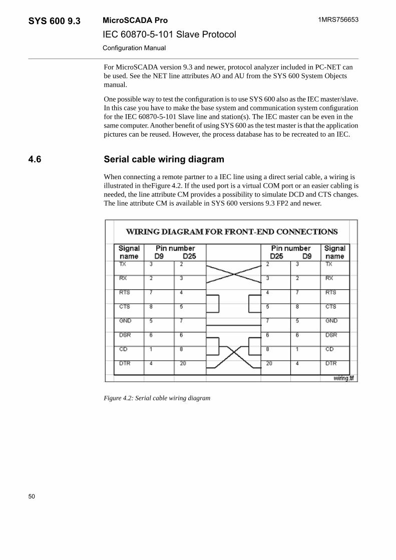
For MicroSCADA version 9.3 and newer, protocol analyzer included in PC-NET canbe used. See the NET line attributes AO and AU from the SYS 600 System Objectsmanual.
One possible way to test the configuration is to use SYS 600 also as the IEC master/slave.In this case you have to make the base system and communication system configurationfor the IEC 60870-5-101 Slave line and station(s). The IEC master can be even in thesame computer. Another benefit of using SYS 600 as the test master is that the applicationpictures can be reused. However, the process database has to be recreated to an IEC.
4.6 Serial cable wiring diagram
When connecting a remote partner to a IEC line using a direct serial cable, a wiring isillustrated in theFigure 4.2. If the used port is a virtual COM port or an easier cabling isneeded, the line attribute CM provides a possibility to simulate DCD and CTS changes.The line attribute CM is available in SYS 600 versions 9.3 FP2 and newer.
Figure 4.2: Serial cable wiring diagram
50
1MRS756653MicroSCADA ProSYS 600 9.3IEC 60870-5-101 Slave ProtocolConfiguration Manual

5 Technical description
5.1 IEC 60870-5-101 Protocol
The IEC Technical Committee 57 (Working Group 03) has developed a protocol standardfor telecontrol, teleprotection and associated telecommunications for electric powersystems. The result of this work is IEC 60870-5. The five first documents listed in Section2.3 specify the base of IEC 60870-5.
The IEC Technical Committee 57 has also generated a companion standard IEC60870-5-101 for telecontrol equipment and systems with coded bit serial data transmissionfor monitoring and controlling geographically widespread processes. This standardutilises the series of documents of IEC 60870-5.
IEC is designed according to the Enhanced Protocol Architecture (EPA) and it specifiesthe following Open Systems Interconnection (OSI) layers:
• Physical layer• Data link layer• Application layer
The physical layer can be any bit-serial physical layer, for example RS-232 C, RS-485,fibre transceiver In SYS 600, the communication takes place using the serial port(s) ofthe base system computer. The interface used is RS-232 C.
A lot of the functionality of the protocol shall be implemented in SCIL by using theapplication and system objects as presented in this document. The reason for this isflexibility and versatility. Although different IEC masters are implemented accordingto the same standard, functionality and requirements still vary from one system andapplication to another. When some of the central parts of message handling areimplemented in SCIL, changes can easily be made, even on-line.
5.2 Level of implementation
In IEC 60870-5-101 the application level messages are called Application Service DataUnits (ASDUs). Each ASDU consists of one or several information objects that containthe actual user data. SYS 600 supports the ASDUs presented in Section5.9 InteroperabilityPrivate ASDUs, i.e. the ones not included in the IEC 60870-5-101 companion standard,are indicated with an asterisk (*). The time stamped command ASDUs 58..64 used inIEC60870-5-104 protocol are mentioned in following chapters but they are not a part ofthe IEC60870-5-101 companion standard. These ASDUs are supported but the usage isnot recommended in IEC60870-5-101.
For more information, see Section 5.9 Interoperability.
51
SYS 600 9.3MicroSCADA Pro
IEC 60870-5-101 Slave Protocol
1MRS756653
31.3.2010Issued:B/30.9.2012Version:
Configuration Manual
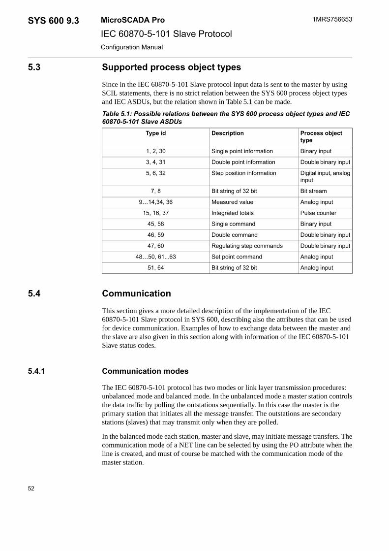
5.3 Supported process object types
Since in the IEC 60870-5-101 Slave protocol input data is sent to the master by usingSCIL statements, there is no strict relation between the SYS 600 process object typesand IEC ASDUs, but the relation shown in Table 5.1 can be made.
Table 5.1: Possible relations between the SYS 600 process object types and IEC60870-5-101 Slave ASDUs
Process objecttype
DescriptionType id
Binary inputSingle point information1, 2, 30
Double binary inputDouble point information3, 4, 31
Digital input, analoginput
Step position information5, 6, 32
Bit streamBit string of 32 bit7, 8
Analog inputMeasured value9…14,34, 36
Pulse counterIntegrated totals15, 16, 37
Binary inputSingle command45, 58
Double binary inputDouble command46, 59
Double binary inputRegulating step commands47, 60
Analog inputSet point command48…50, 61...63
Analog inputBit string of 32 bit51, 64
5.4 Communication
This section gives a more detailed description of the implementation of the IEC60870-5-101 Slave protocol in SYS 600, describing also the attributes that can be usedfor device communication. Examples of how to exchange data between the master andthe slave are also given in this section along with information of the IEC 60870-5-101Slave status codes.
5.4.1 Communication modes
The IEC 60870-5-101 protocol has two modes or link layer transmission procedures:unbalanced mode and balanced mode. In the unbalanced mode a master station controlsthe data traffic by polling the outstations sequentially. In this case the master is theprimary station that initiates all the message transfer. The outstations are secondarystations (slaves) that may transmit only when they are polled.
In the balanced mode each station, master and slave, may initiate message transfers. Thecommunication mode of a NET line can be selected by using the PO attribute when theline is created, and must of course be matched with the communication mode of themaster station.
52
1MRS756653MicroSCADA ProSYS 600 9.3IEC 60870-5-101 Slave ProtocolConfiguration Manual

The serial bus topology (multi-drop) can be used only in theunbalanced mode.
5.4.2 Protocol converter
Each IEC 60870-5-101 Slave station configured on a line of a NET unit acts as a protocolconverter between the IEC 60870-5-101 protocol and a base system. An internal protocolof SYS 600 is used in communication between the SYS 600 nodes, for example, betweena base system and a NET unit.
Unlike in some other slave protocols, a IEC 60870-5-101 Slave station does not have adatabase in the NET unit, all data is sent directly to the master station. Therefore nodatabase intialisation procedures are needed. If needed, messages are stored temporarilyinto queues inside the NET unit.
In IEC 60870-5-101 data sent from the slave to the master can be assigned to two classes:class 1 or class 2. The data from the classes is sent to the master either by polling(unbalanced mode) or spontaneously (balanced mode). In SYS 600 the class assignmentis done when the IEC message is written to the NET unit by using SCIL statements. Ingeneral, class 1 is used for high priority data and class 2 for lower priority data. The classis defined with the index value in the SD- and EV-attribute writes.
Both class 1 and class 2 queues contain space for 200 IEC60870-5-104 messages. At itsmaximum, one queue may buffer about 4000 binary events (ASDU 30, M_SP_TB_1).
5.4.3 Addressing
In IEC 60870-5-101 there are three kinds of addresses:
• Link address: the address of the IEC link. This address is defined by the PA (PollingAddress) attribute of the IEC station. In most cases it is the same as the stationaddress.
• Station address: a common address of an ASDU. There can be several commonaddresses of an ASDU with the same link address. This address is defined by theSA (Station Address) attribute of the IEC station.
• Signal address: an information object address. This address is unique for each signalwith the same common address of an ASDU. The Information object address canbe given in two ways:
- As an unstructured address, which is basically just an integer within the rangeof the information object address.
- As a structured address which is given byte-wise so that each byte usuallyrepresents a level in a hierarchical structure. For example, upper byte = unitnumber and lower byte = signal address.
SYS 600 supports only unstructured addresses. However, this does not preventcommunication with the IEC 60870 slaves using structured addresses, since the two
53
SYS 600 9.3MicroSCADA Pro
IEC 60870-5-101 Slave Protocol
1MRS756653
31.3.2010Issued:B/30.9.2012Version:
Configuration Manual

types of addresses just demonstrate two different ways of presenting the same address.For example, a two-byte address can be represented as follows:
unstructured = 256*upper byte + lower byte.
5.4.4 Data flow
Figure 5.1 describes the data flow between the process devices and the IEC master. Bothdirections are described separately since the data is handled in a different way dependingon the direction.
See manual COM 500i User's guide for detailed information about the data flowconfiguration.
Figure 5.1: Data flow between the process devices and the IEC master in COM 500i
Input data
When input data, for example indications and measured values, are sent from the processdevices to the IEC master, the following steps are taken:
54
1MRS756653MicroSCADA ProSYS 600 9.3IEC 60870-5-101 Slave ProtocolConfiguration Manual

1. The process devices send data to the SYS 600 process database.2. The updated process object activates an event channel.3. The event channel executes a command procedure. Some of the attributes of the
process object are given as arguments to the command procedure.4. The command procedure sends the data to the NET database by using the SD and
EV attributes based on specific cross-reference information.5. The NET unit sends data to the IEC master either as static or unsolicited data.
The cross-reference information is the data needed to deliver the signal to the IEC master,for example object address and message type.
The number event channels and command procedures needed to deliver data to the masterdepends on the application, one solution is to have one command procedure for eachprocess object type. Examples of the command procedures are given later in thisdocument.
Output data
When output data, for example object commands and analog setpoints, are sent from theIEC master to the process devices, the following steps are taken:
1. The command is received by the SYS 600 process database. There must be a separateinput process object for each IEC command address. This part of the process objectis created manually when the signal engineering is done.
2. The updated process object activates an event channel.3. The event channel executes a command procedure. Some of the attributes of the
process object are given as arguments to the command procedure.4. The command procedure sends the process devices by setting the corresponding
output process object(s) and, if required, sends a confirmation to the IEC master viathe NET unit.
Cross-reference data can also be used with commands. It can contain, for example,information of the logical names and indices of the output process objects. Examples ofthe command procedures are given later in this document.
Other messages
In addition to the input and output data described above, there are also some othermessages transferred between the master and the slave. These messages contain forexample synchronization commands and interrogation commands. Some of thesecommands are handled automatically by the NET unit while others require SCILprogramming. The ones that require SCIL programming are described in detail later inthis document.
System and application commands are sent to the process database as follows:
• System commands (for example test command) are sent to a bit stream processobject.
• Application commands (for example general interrogation) are sent to an analoginput (AI) process object.
55
SYS 600 9.3MicroSCADA Pro
IEC 60870-5-101 Slave Protocol
1MRS756653
31.3.2010Issued:B/30.9.2012Version:
Configuration Manual

Using these process objects the messages can be interpreted and processed by usingSCIL. Unrecognised commands from the IEC master can be received by the bit streamprocess object. This feature is configurable by using the RM attribute of the IEC slavestation.
5.4.5 Redundancy
SYS 600 supports redundant lines for both the balanced and unbalanced mode. The useof this feature requires that the corresponding functionality is also implemented in theIEC master, as stated in the document “Norwegian User Conventions for IEC60870-5-101”.
The master controls the mechanism that activates a line switch. The main linecommunication works as without redundancy. However, the master sends only a cyclical“request status of link” message on the back-up line, to which the slave responses witha “status of link” message. No other messages are allowed. When the master wants toswitch lines, it sends a “reset of link” message to the redundant line, which the slaveacknowledges. After this the former main line acts as the former back-up line and viceversa. In the balanced mode, the links are initialized in both directions in the main lineand also in the backup line. The main line operates normally and a cyclical “test functionof link” message is transmitted on the backup line. The line switch occurs only whenthe master issues a command to the backup line. Bit 1 of the line attribute OM providesan optional functionality in the behaviour of the backup line.
5.4.6 Device communication attributes
Transparent DataTD
The TD attribute is used for sending transparent data (for example SPA messages) tothe IEC master as a response to the Read command (ASDU 102).
VectorData type:
Value Vector (TYPE, ADDR, COT, TDT)
0...255, for other parameters but ADDRValue range:
Write-onlyAccess:
Description of the vector parameters:
Type identification of the ASDU, integer. The type identificationsshown in Table 5.2 are allowed when transparent data is sent to theIEC master/slave by using the TD attribute.
TYPE:
Table 5.2: The type identifications allowed when using the TD attributeDescriptionASDUType id
101 Encapsulated SPA bus reply messageM_SB_NA_1130
56
1MRS756653MicroSCADA ProSYS 600 9.3IEC 60870-5-101 Slave ProtocolConfiguration Manual

Information object address, integerADDR:
0...255, when IL attribute = 10...65535, when IL attribute = 20...16777215, when IL attribute = 3
Value range:
Cause of transmission of the message, integer. Valid value: 7 = activ-ation confirmation
COT:
Transparent data (for example SPA message) as a text stringTDT:
For more detailed information, see the examples and the interoperability list later in thisdocument.
Spontaneous DataSD
Enables SYS 600 to send spontaneous or cyclic data to the IEC master. This data is sentwithout time stamp. By reading the SD attribute the user can enquire the number of datamessages (ASDUs) in the queues not yet sent to the IEC master. When reading, thestation attribute QI is recommeded since it provides more specific information about thecontents of the queues during runtime.
Vector or integerData type:
When writing:Value:
Vector (TYPE, ADDR, VAL, COT, QU, PRI, OW)
When reading: Integer
1...2, 101...102Index range:
When writing:The number of the class the message is assigned to.If value 101 isgiven, the item is added to class 1 queue but is not sent until an indexvalue 1 or 2 is written.If value 102 is given, the item is added to class 2 queue but is not sentuntil an index value 1 or 2 is written.When reading: the index is meaningless, the returned value is thenumber of ASDUs not yet sent to the IEC master.If station attribute MT is bigger than 0, instead of reading of the SD-attribute, it is preferable to use the attribute QI.
Indexes 101 and 102 are useful only in the balanced mode.
No limitationsAccess:
Description of the vector parameters:
Type identification of the ASDU as a text string (for example“M_IT_NA_1”)
TYPE:
The type identifications presented in Table 5.3 are allowed when data is sent to the IECmaster by using the SD attribute.
57
SYS 600 9.3MicroSCADA Pro
IEC 60870-5-101 Slave Protocol
1MRS756653
31.3.2010Issued:B/30.9.2012Version:
Configuration Manual

Table 5.3: The type identifications allowed when using the SD attributeDescriptionASDUType id
Single-point information without timetag
M_SP_NA_11
Double-point information without timetag
M_DP_NA_13
Step position informationM_ST_NA_15
Bit string of 32 bitM_BO_NA_17
Measured value, normalised valueM_ME_NA_19
Measured value, scaled valueM_ME_NB_111
Measured value, short floating pointnumber
M_ME_NC_113
Integrated totalsM_IT_NA_115
End of initialisationM_EI_NA_170
Parameter of measured values, normal-ized value
P_ME_NA_1110
Parameter of measured values, scaledvalue
P_ME_NB_1111
Parameter of measured values, shortfloating point number
P_ME_NC_1112
Information object addressADDR:
0...255,when IL attribute = 1
Value range:
0...65535,when IL attribute = 2
0...16777215,when IL attribute = 3
The value of the object. The value range depends on the data objecttype. For more information about the SCIL programs, refer to Sec-tion 5.5.2.1 Command procedures for process data.
VAL:
Cause of transmission of the ASDU. This parameter describes thereason why a message is sent. If the originator address is used, it canbe set by adding 256*originator address to the COT value. The causesof transmission as shown in Table 5.4 are valid when using the SDattribute.
COT:
Table 5.4: The causes of transmission valid for the SD attributeDescriptionCOT
Periodic, cyclic1
Background scan2
Spontaneous3
58
1MRS756653MicroSCADA ProSYS 600 9.3IEC 60870-5-101 Slave ProtocolConfiguration Manual

Initialised4
Request or requested5
Return information caused by a remote command11
Return information caused by a local command12
Integer 1...255, bit mask of the qualifier descriptor bits of the ASDU.Qualifier descriptor bits indicate the current state of the data object.The bits in the qualifier byte are different for different ASDUs (seethe examples later in this document). The relation between the quali-fier descriptor bits and process object attributes is presented inTable 5.5.
QU:
Table 5.5: The relation between the qualifier descriptor bits and process objectattributes
Attr.DescriptionNameBit
OS ==1A value is valid if it was correctly acquired.After the acquisition function recognises ab-normal conditions of the information source(missing or non-operating updating devices),the value is then marked invalid. The valueof the information object is not defined underthis condition. The mark Invalid is used toindicate to the destination that the value maybe incorrect and cannot be used.
InvalidIV
OS ==2A value is topical if the most recent updatewas successful. It is not topical if it was notsuccessfully updated during a specified timeinterval or it is unavailable.
Not topicalNT
SBThe value of the information object isprovided by input of an operator (dispatcher)or by an automatic source.
SubstitutedSB
BLThe value of the information object isblocked for transmission; the value remainsin the state that was acquired before it wasblocked. Blocking and deblocking may beinitiated e.g. by a local lock or a local auto-matic cause.
BlockedBL
-Counter was/was not adjusted since the lastreading.
Counter adjustedCA
ORThe value of the information object is beyonda predefined range of value (mainly applic-able to analogue values).
OverflowOV
OFCounter overflow occurred/did not occur inthe corresponding integration period.
CarryCY
Priority of the information object. This parameter defines how theinformation object sent using the SD attribute is placed in the class 1and class 2 queues. This parameter can be used for setting the priorityof data types or individual objects.
PRI:
59
SYS 600 9.3MicroSCADA Pro
IEC 60870-5-101 Slave Protocol
1MRS756653
31.3.2010Issued:B/30.9.2012Version:
Configuration Manual

Integer 0 … 3:Value:
0 = The information object is always placed in the end of the queue.
1 or 2 = The information object is placed in the queue according tothe priority value. Objects with higher priority pass the lower priorityobjects. If the queue contains more than one object with the samepriority, the new object is placed behind them.
3 = The information object is always placed in the beginning of thequeue.
This parameter defines whether a new information object overwritesan older information object in the queue.
OW:
Integer 0 or 1Value:
0 = No overwriting
1 = A new information object overwrites an older object in the queue
Event Data with Time StampEV
By writing data to the EV attribute the user can send event data, that is, time-taggedmessages from SYS 600 to the master. By reading the EV attribute the user can enquirethe number of information objects (events) in the queue not yet sent to the IEC master.The maximum value of the EV attribute is limited by the RW attribute of the IEC slavestation.
Vector or integerData type:
When writing: Vector (TYPE, ADDR, VAL, COT, QU, PRI, RT,RM, [CTRL])
Value:
When reading, Integer 0...65535
1...2, 101...102Index range:
When writing: the number of the class the message is assigned to.
If value 101 is given, the item is added to class 1 queue but is not sentuntil an index value 1 or 2 is written. If value 102 is given, the itemis added to class 2 queue but is not sent until an index value 1 or 2 iswritten.
When reading: the index is meaningless, returned value is the numberof data items not yet sent to the IEC master. If station attribute MT isbigger than 0, instead of reading of the EV-attribute, it is preferableto use the attribute QI.Indexes 101 and 102 are useful only in the balanced mode.
No limitationsAccess:
Description of the vector parameters:
60
1MRS756653MicroSCADA ProSYS 600 9.3IEC 60870-5-101 Slave ProtocolConfiguration Manual
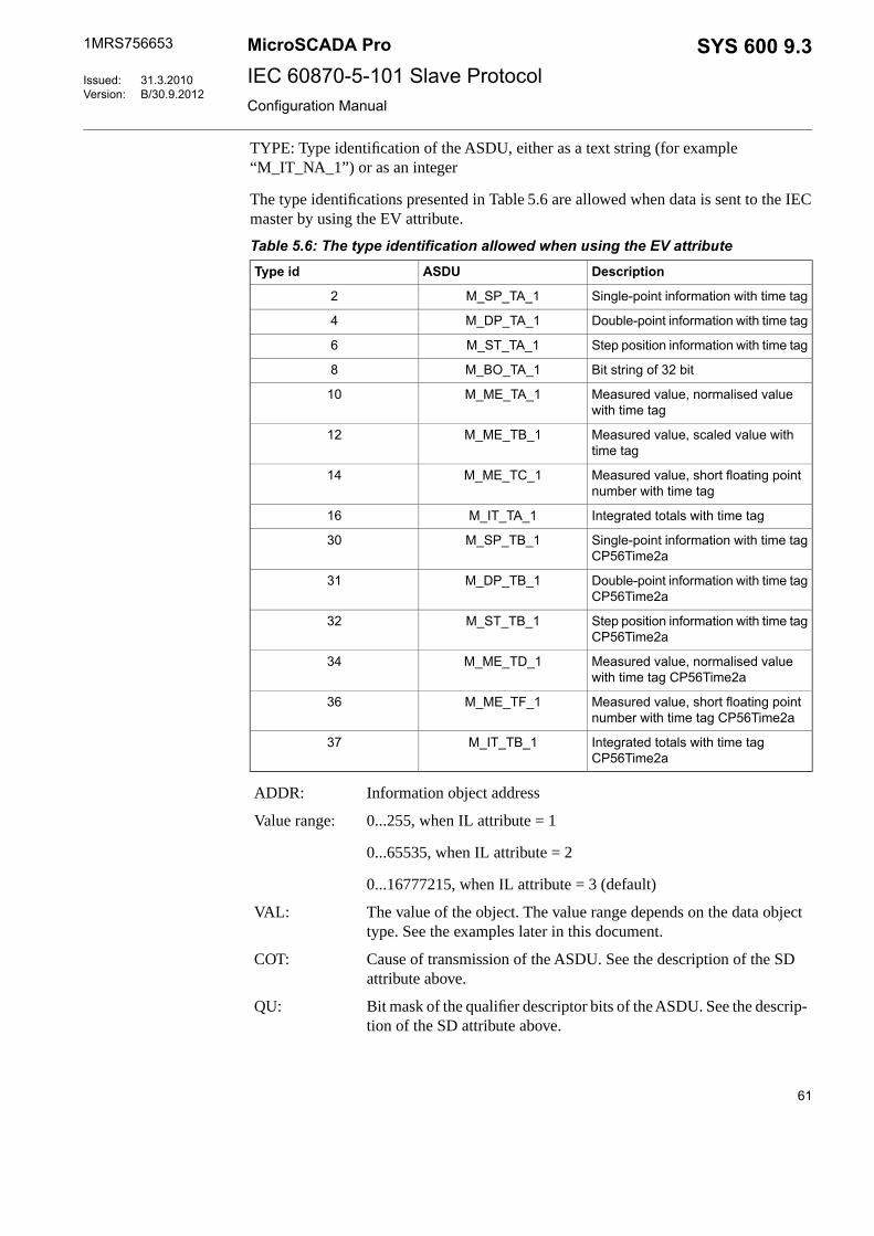
TYPE: Type identification of the ASDU, either as a text string (for example“M_IT_NA_1”) or as an integer
The type identifications presented in Table 5.6 are allowed when data is sent to the IECmaster by using the EV attribute.
Table 5.6: The type identification allowed when using the EV attributeDescriptionASDUType id
Single-point information with time tagM_SP_TA_12
Double-point information with time tagM_DP_TA_14
Step position information with time tagM_ST_TA_16
Bit string of 32 bitM_BO_TA_18
Measured value, normalised valuewith time tag
M_ME_TA_110
Measured value, scaled value withtime tag
M_ME_TB_112
Measured value, short floating pointnumber with time tag
M_ME_TC_114
Integrated totals with time tagM_IT_TA_116
Single-point information with time tagCP56Time2a
M_SP_TB_130
Double-point information with time tagCP56Time2a
M_DP_TB_131
Step position information with time tagCP56Time2a
M_ST_TB_132
Measured value, normalised valuewith time tag CP56Time2a
M_ME_TD_134
Measured value, short floating pointnumber with time tag CP56Time2a
M_ME_TF_136
Integrated totals with time tagCP56Time2a
M_IT_TB_137
Information object addressADDR:
0...255, when IL attribute = 1Value range:
0...65535, when IL attribute = 2
0...16777215, when IL attribute = 3 (default)
The value of the object. The value range depends on the data objecttype. See the examples later in this document.
VAL:
Cause of transmission of the ASDU. See the description of the SDattribute above.
COT:
Bit mask of the qualifier descriptor bits of the ASDU. See the descrip-tion of the SD attribute above.
QU:
61
SYS 600 9.3MicroSCADA Pro
IEC 60870-5-101 Slave Protocol
1MRS756653
31.3.2010Issued:B/30.9.2012Version:
Configuration Manual
Integer 1...255Value:
Priority of the information object. See the description of the SD attrib-ute above.
PRI:
Integer 0...3Value:
If value = 255 is given, the event data is not recorded. However thetimestamp given with the RT and RM attributes is recorded as thetimestamp of the event buffer overflow situation. A single indicationmessage using this timestamp is transmitted automatically as the firstevent message when the communicating to the master proceeds. Theinformation object address of the event is defined with the EA stationattribute. If a percentage value defined with attribute EA index 2 isdefined to be less than 100, the event is sent only if the current stateof the queues is below or equal to the defined level.
Registration time. The registration time included in the time stampof the unsolicited message.
RT:
Registration milliseconds. The millisecond part of the time stamp ofthe unsolicited message.
RM:
Integer 0...999Value:
62
1MRS756653MicroSCADA ProSYS 600 9.3IEC 60870-5-101 Slave ProtocolConfiguration Manual

This is an optional field, which can be given to define the contents ofthe information object more specifically. The value is a bit pattern.Bits 1 and 2 control the 'summer time' bit of the timestamp of theoutgoing event messages. The term 'summer time' is used in IECstandards as a synonym for 'daylight saving time'.
CTRL:
Values of the 'summer time' bit are:
0 = standard time
1= summer time/daylight saving time.
This bit exists only in ASDU types with extension 'with time tagCP56tIME2a'. In monitor direction the corresponding ASDU numbersare 30..40. These ASDU numbers are usually used only withIEC60870-5-104 slave protocol and not with IEC60870-5-101 slave.
Bit 0 = 0: The 'time invalid' bit of the timestamp of this informationobject is not explicitly set, but it follows the value of the station attrib-ute IV.
Bit 0 = 1: The 'time invalid' bit of the timestamp of this informationobject is set to state 1 = invalid.
Bit 1 = 0: The 'summer time' bit of the timestamp of this informationobject is not explicitly set, but it follows the value of the station attrib-ute SU.
Bit 1 = 1: The 'summer time' bit of the timestamp of this informationobject is set to state 1 = summertime.
Bit 2 = 0: No conversion from UTC (Coordinated Universal Time)time to local time is requested. The given timestamp is sent as suchand the state 'summer time' bit follows the rules defined in the descrip-tion of the bit 1 above.
Bit 2 = 1: The timestamp is given as an UTC time and the conversionto the local time is requested. The timestamp of the event messagewill be converted to the local time of the computer and the 'summertime' bit of the timestamp will be set according to the localized eventtimestamp. The setting of bit 2 will override the 'summer time' bitsetting rules defined in the description of the bit 1 above.
Command ConfirmationCF
Manual confirmation of the received messages. In IEC 60870-5-101 commands receivedby the slave station are confirmed by using specific confirmation messages. They arebasically original command messages with a different Cause Of Transmission (COT).Confirmation can be either positive or negative. The number of confirmations and theCOT used depends on the type of the command. See the examples later in this document.
63
SYS 600 9.3MicroSCADA Pro
IEC 60870-5-101 Slave Protocol
1MRS756653
31.3.2010Issued:B/30.9.2012Version:
Configuration Manual

In SYS 600 the CF attribute is used to confirm received messages manually. When theuser writes only the COT value to the CF attribute, NET sends the confirmation messagewith written COT to the master. In this case the confirmation message is formed fromthe latest received command.
The user may also define which command is confirmed. NET automatically stores theincoming commands to an internal table (70 latest commands are stored). In case ADDR(or ADDR and TYPE) is given in CF-writing, the confirmed command is searched (latestfirst) from the table. If no command with matching address (or address and ASDU-type)is found, error ICCC_NO_ACTIVE_COMMAND is returned and the confirmationmessage is not sent. If a matching command is found, the given COT is set and thecommand is sent as a confirmation.
VectorData type:
Value Vector (COT, [ADDR, [TYPE, [PRIO]]])
Write-onlyAccess:
Description of the vector parameters:
COT: Cause of transmission of the confirmation message, integer. This parameterdescribes the reason why a message is sent. By adding 64 to the COT value, theconfirmation is set negative, i.e. the command is not accepted or failed. If the originatoraddress is used, it can be set by adding 256*originator address to the COT value. Thecauses of transmission shown in Table 5.7 are valid when using the CF attribute.
Table 5.7: The causes of transmission valid for the CF attributeDescriptionCOT
Activation confirmation7
Deactivation confirmation9
Activation termination10
Information object address of the confirmed command, integer. Fordata commands, this is the address of the process object receiving thecommand. For system commands the address must be resolved fromthe command message and for application commands the address is0.
ADDR:
0...255, when IL attribute = 1Value range:
0...65535, when IL attribute = 2
0...16777215, when IL attribute = 3 (default)
Type identification of the ASDU, integer. The CF attribute can alsobe used for sending transparent data as an IEC 60870-5-104 confirm-ation message. See the ASDUs and transport mechanisms later in thisdocument.
TYPE:
Priority of the confirmation message 0..4 (or 100..104 or 200..204when the queue needs to be defined)
PRIO:
64
1MRS756653MicroSCADA ProSYS 600 9.3IEC 60870-5-101 Slave ProtocolConfiguration Manual

The priority of the confirmation message cannot be specified, if the transparent data issent described below. For other ASDU types, the defining of the priority is possible andthe used values are the same as in the SD and EV attributes. A bigger value means higherpriority.
The messages are sorted in the transmission queue so that the higher priority messagesare sent first. The priority is optional and if not specified, fixed values which depend ona given COT value are used. If the value of the PRIO is 100..104, the confirmationmessages are always placed to the class 1 queue. Correspondingly, if the value of thePRIO is 200..204, the confirmation messages are always placed to the class 2 queue.When the queue is explicitly defined using PRIO values >= 100, the actual priority inthe queue will be PRIO modulo 100. With PRIO values 0..4 or when the PRIO is notdefined, the queue selection is based on the value of the RM attribute, bit 2.
The type identifications presented in Table 5.8 are allowed commands ASDUs confirmedby the CF attribute.
Table 5.8: The type identifications allowed when using the CF attributeDescriptionASDUType id
Single commandC_SC_NA_145
Double commandC_DC_NA_146
Regulating step commandC_RC_NA_147
Set point command, normalised valueC_SE_NA_148
Set point command, scaled valueC_SE_NB_149
Set point command, short floating point numberC_SE_NC_150
Bit string of 32 bitC_BO_NA_151
Single command with time tag CP56Time2aC_SC_TA_158
Double command with time tag CP56Time2aC_DC_TA_159
Regulating step command with time tag CP56Time2aC_RC_TA_160
Set point command, normalized value with CP56Time2aC_SE_TA_161
Set point command, scaled value withCP56Time2aC_SE_TB_162
Set point command, short floating point number with CP56Time2aC_SE_TE_163
Bit string of 32 bit with CP56Time2aC_BO_TA_164
Interrogation commandC_IC_NA_1100
Counter interrogation commandC_CI_NA_1101
Read commandC_RD_NA_1102
Clock synchronisation commandC_CS_NA_1103
Test commandC_TS_NA_1104
Reset process commandC_RP_NA_1105
Test command with CP56Time2aC_TS_TA_1107
Parameter of measured values, normalized valueP_ME_NA_1110
Parameter of measured values, scaled valueP_ME_NB_1111
65
SYS 600 9.3MicroSCADA Pro
IEC 60870-5-101 Slave Protocol
1MRS756653
31.3.2010Issued:B/30.9.2012Version:
Configuration Manual
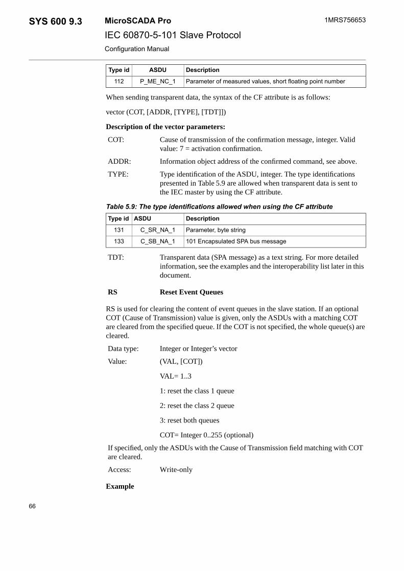
DescriptionASDUType id
Parameter of measured values, short floating point numberP_ME_NC_1112
When sending transparent data, the syntax of the CF attribute is as follows:
vector (COT, [ADDR, [TYPE], [TDT]])
Description of the vector parameters:
Cause of transmission of the confirmation message, integer. Validvalue: 7 = activation confirmation.
COT:
Information object address of the confirmed command, see above.ADDR:
Type identification of the ASDU, integer. The type identificationspresented in Table 5.9 are allowed when transparent data is sent tothe IEC master by using the CF attribute.
TYPE:
Table 5.9: The type identifications allowed when using the CF attributeDescriptionASDUType id
Parameter, byte stringC_SR_NA_1131
101 Encapsulated SPA bus messageC_SB_NA_1133
Transparent data (SPA message) as a text string. For more detailedinformation, see the examples and the interoperability list later in thisdocument.
TDT:
Reset Event QueuesRS
RS is used for clearing the content of event queues in the slave station. If an optionalCOT (Cause of Transmission) value is given, only the ASDUs with a matching COTare cleared from the specified queue. If the COT is not specified, the whole queue(s) arecleared.
Integer or Integer’s vectorData type:
(VAL, [COT])Value:
VAL= 1..3
1: reset the class 1 queue
2: reset the class 2 queue
3: reset both queues
COT= Integer 0..255 (optional)
If specified, only the ASDUs with the Cause of Transmission field matching with COTare cleared.
Write-onlyAccess:
Example
66
1MRS756653MicroSCADA ProSYS 600 9.3IEC 60870-5-101 Slave ProtocolConfiguration Manual

#SET STA1:SRS=(3,20) ; Clears the ASDUs with COT=20 (Interrogated)from queues
; 1 and 2
5.5 Command procedures
5.5.1 Command procedures in COM 500i
Signals are sent from the process units to a NCC and commands from a NCC to theprocess unit. COM 500i reroutes the signals using command procedures andcross-references, see Figure 5.2. The command procedures, which are used for signalrerouting, are described here.
Figure 5.2: COM 500i reroutes the signals
If the IEC 60870-5-101 Slave protocol is used with COM 500i, the command proceduresavailable for COM 500i are used. The cross-reference information is entered in the SignalCross-reference tool. In order to receive more information, see SYS 600 COM 500iUser’s Guide Table 5.10 shows the used COM 500i command procedures and eventchannels.
Table 5.10: Used event channels and command proceduresCommand ProcedureEvent ChannelProcess Object Type
COM_USAICOM_USAIAnalog Input
COM_USDICOM_USDISingle Indication
COM_USDBCOM_USDBDouble Indication
COM_USDICOM_USDIDigital Input
67
SYS 600 9.3MicroSCADA Pro
IEC 60870-5-101 Slave Protocol
1MRS756653
31.3.2010Issued:B/30.9.2012Version:
Configuration Manual
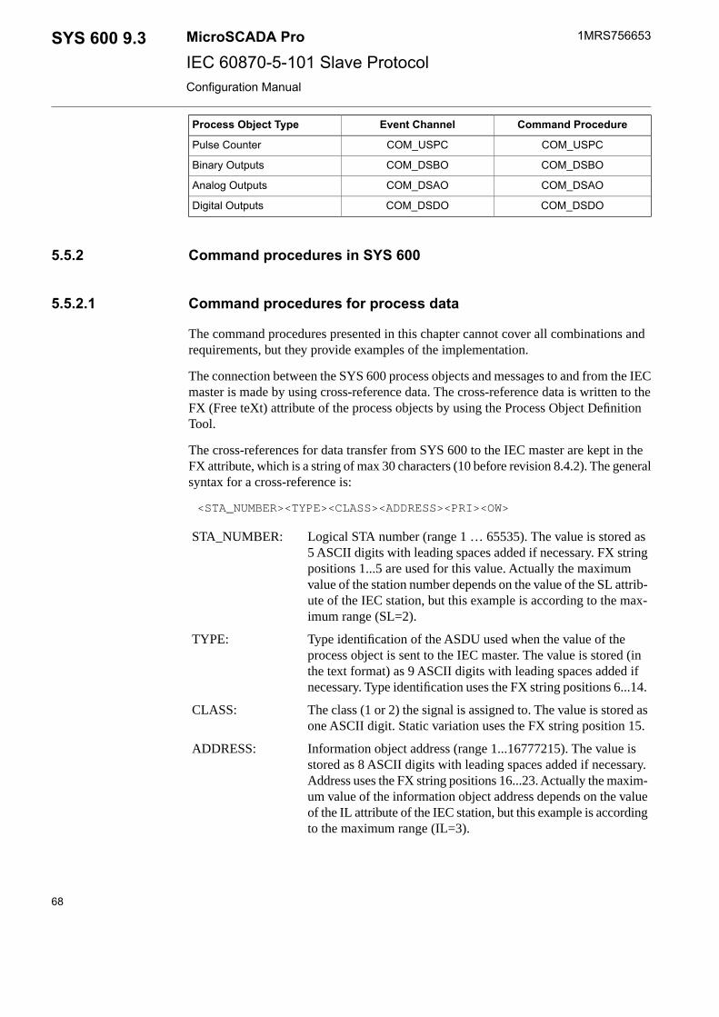
Command ProcedureEvent ChannelProcess Object Type
COM_USPCCOM_USPCPulse Counter
COM_DSBOCOM_DSBOBinary Outputs
COM_DSAOCOM_DSAOAnalog Outputs
COM_DSDOCOM_DSDODigital Outputs
5.5.2 Command procedures in SYS 600
5.5.2.1 Command procedures for process data
The command procedures presented in this chapter cannot cover all combinations andrequirements, but they provide examples of the implementation.
The connection between the SYS 600 process objects and messages to and from the IECmaster is made by using cross-reference data. The cross-reference data is written to theFX (Free teXt) attribute of the process objects by using the Process Object DefinitionTool.
The cross-references for data transfer from SYS 600 to the IEC master are kept in theFX attribute, which is a string of max 30 characters (10 before revision 8.4.2). The generalsyntax for a cross-reference is:
<STA_NUMBER><TYPE><CLASS><ADDRESS><PRI><OW>
Logical STA number (range 1 … 65535). The value is stored as5 ASCII digits with leading spaces added if necessary. FX stringpositions 1...5 are used for this value. Actually the maximumvalue of the station number depends on the value of the SL attrib-ute of the IEC station, but this example is according to the max-imum range (SL=2).
STA_NUMBER:
Type identification of the ASDU used when the value of theprocess object is sent to the IEC master. The value is stored (inthe text format) as 9 ASCII digits with leading spaces added ifnecessary. Type identification uses the FX string positions 6...14.
TYPE:
The class (1 or 2) the signal is assigned to. The value is stored asone ASCII digit. Static variation uses the FX string position 15.
CLASS:
Information object address (range 1...16777215). The value isstored as 8 ASCII digits with leading spaces added if necessary.Address uses the FX string positions 16...23. Actually the maxim-um value of the information object address depends on the valueof the IL attribute of the IEC station, but this example is accordingto the maximum range (IL=3).
ADDRESS:
68
1MRS756653MicroSCADA ProSYS 600 9.3IEC 60870-5-101 Slave ProtocolConfiguration Manual

The priority of the information object in the NET queues. Thevalue is stored as one ASCII digit. Priority parameter uses theFX string position 24.
PRI:
The parameter that determines whether the information objectoverwrites an older one with the same address in the NET queues.Stored as one ASCII digit. The overwrite parameter uses the FXstring position 25.
OW:
The used STA object attribute depends on whether the information object is sent withor without a time tag, i.e. as static data or event. The qualifier byte is derived from theattributes of the process object.
An example of the cross-reference of a double indication signal assigned to class 1 andsent with time tag, overwrite and high priority.
133026511_AT_PD_M1FX
098765432109876543210987654321CHAR
Another example of the cross-reference of a scaled analog input signal assigned to class2 and sent without time tag, no overwrite and low priority.
00917721_BN_EM_M1FX
098765432109876543210987654321CHAR
Analog inputs
In the IEC 60870-5-101 protocol analog values can be sent in three different ways:
• As 32-bit floating point values.• As normalised values, i.e. as 16-bit fixed point values with range –1...1-(2/32768).• As scaled values, i.e. as 16-bit integers with range –32768...32767.
When analog values are sent to NET by using the SD and EV attributes, both thenormalised and scaled values are handled as signed 16-bit integers. This means that themaximum value of the analog signal is written as value 32767 and the minimum valueis written as value –32768. The interpretation of the value is done by the IEC masterbased on the type identification of the ASDU.
If an analog signal is sent as a normalised or scaled value, it must be limited or scaledto the value range –32768...32767. This can happen, for example, by using a specificscale object and the SCIL SCALE function.
All the analog values are connected to the same event channel/command procedurecombination. The command procedure is activated each time the process object is updated.It reads the updated value, and if necessary, limits or scales it and sends it to NET byusing the cross-reference data. An example of the command procedure is listed below.A linear scale object AI_TO_S16 is used for the scaling of the analog values with thevalue range as presented in Table .
69
SYS 600 9.3MicroSCADA Pro
IEC 60870-5-101 Slave Protocol
1MRS756653
31.3.2010Issued:B/30.9.2012Version:
Configuration Manual

Table 5.11: The value range for analog values that are to be sent to NETSYS 600 Data-base
Process
-32767-32768Low
3276732768High
This object does not scale the value but limits it to the correct range. If scaling is alsowanted, it can be done by changing the “process” side value range.
ERROR CONTINUE
;read cross-reference data
@FX = 'LN':PFX'IX'
@STA_NR = DEC_SCAN(SUBSTR(%FX,1,5))
@TYPE = SUBSTR(%FX,6,9)
@CLASS = DEC_SCAN(SUBSTR(%FX,15,1))
@ADDR = DEC_SCAN(SUBSTR(%FX,16,8))
@PRI = DEC_SCAN(SUBSTR(%FX,24,1))
@OW = DEC_SCAN(SUBSTR(%FX,25,1))
;scale the value if scaled or normalised value, and set theoverfow bit
#CASE SUBSTR(%TYPE,7,1)
#WHEN "A","B" #BLOCK
#IF %AI < -32768 OR %AI > 32767 #THEN #BLOCK
@VALUE = ROUND(SCALE(%AI,"AI_TO_S16","INPUT"))
@OR = 1
#BLOCK_END
#ELSE #BLOCK
@VALUE = ROUND(%AI)
@OR = 0
#BLOCK_END
#BLOCK_END
#OTHERWISE #BLOCK
@VALUE = %AI
@OR = 0
#BLOCK_END
#CASE_END
;calculate the qualifier byte
#IF %OS == 2 #THEN @NT = 1
#ELSE @NT = 0
#IF %OS == 1 OR %OS == 10 #THEN @IV = 1
#ELSE @IV = 0
@QUALIFIER = %OR+16*%BL+32*%SB+64*%NT+128*%IV
;send data to NET with spontaneous COT
#IF SUBSTR(%TYPE,6,1) == "T" #THEN - ;send with time tag
#SETSTA'STA_NR':SEV(%CLASS)=(%TYPE,%ADDR,%VALUE,3,%QUALIFIER,%PRI,%RT,%RM)
#ELSE - ;send without time tag
70
1MRS756653MicroSCADA ProSYS 600 9.3IEC 60870-5-101 Slave ProtocolConfiguration Manual

#SETSTA'STA_NR':SSD(%CLASS)=(%TYPE,%ADDR,%VALUE,3,%QUALIFIER,%PRI,%OW)
Single indications
All the binary inputs are connected to an event channel/command procedure combinationthat sends the process value to the NET unit. The command procedure is activated eachtime the process object is updated. It reads the updated value and sends it to NET byusing cross-reference data. An example of the command procedure is listed below:
#ERROR CONTINUE
;read cross-reference data
@FX = 'LN':PFX'IX'
@STA_NR = DEC_SCAN(SUBSTR(%FX,1,5))
@TYPE = SUBSTR(%FX,6,9)
@CLASS = DEC_SCAN(SUBSTR(%FX,15,1))
@ADDR = DEC_SCAN(SUBSTR(%FX,16,8))
@PRI = DEC_SCAN(SUBSTR(%FX,24,1))
@OW = DEC_SCAN(SUBSTR(%FX,25,1))
;calculate the qualifier byte
#IF %OS == 2 #THEN @NT = 1
#ELSE @NT = 0
#IF %OS == 1 OR %OS == 10 #THEN @IV = 1
#ELSE @IV = 0
@QUAL= %BI+2+16*%BL+32*%SB+64*%NT+128*%IV
;send data to NET with spontaneous COT
#IF SUBSTR(%TYPE,6,1) == "T" #THEN - ;send with time tag
#SETSTA'STA_NR':SEV(%CLASS)=(%TYPE,%ADDR,%BI,3,%QUAL,%PRI,%RT,%RM)
#ELSE - ;send without time tag
#SET STA'STA_NR':SSD(%CLASS)=(%TYPE,%ADDR,%BI,3,%QUAL,%PRI,%OW)
Double indications
All the double binary inputs are connected to an event channel/command procedurecombination that sends the process value to the NET unit. The command procedure isactivated each time the process object is updated. It reads the updated value and sendsit to NET by using the cross-reference data. An example of the command procedure islisted below:
#ERROR CONTINUE
;read cross-reference data
@FX = 'LN':PFX'IX'
@STA_NR = DEC_SCAN(SUBSTR(%FX,1,5))
@TYPE = SUBSTR(%FX,6,9)
@CLASS = DEC_SCAN(SUBSTR(%FX,15,1))
71
SYS 600 9.3MicroSCADA Pro
IEC 60870-5-101 Slave Protocol
1MRS756653
31.3.2010Issued:B/30.9.2012Version:
Configuration Manual

@ADDR = DEC_SCAN(SUBSTR(%FX,16,8))
@PRI = DEC_SCAN(SUBSTR(%FX,24,1))
@OW = DEC_SCAN(SUBSTR(%FX,25,1))
;calculate the qualifier byte
#IF %OS == 2 #THEN @NT = 1
#ELSE @NT = 0
#IF %OS == 1 OR %OS == 10 #THEN @IV = 1
#ELSE @IV = 0
@DPIS = (0,2,1,3)
@DPI = %DPIS(%DB+1)
@QUAL = BIT(%DPI,0)+2*BIT(%DPI,1)+16*%BL+32*%SB+64*%NT+128*%
;send data to NET with spontaneous COT
#IF SUBSTR(%TYPE,6,1) == "T" #THEN - ;send with time tag
#SETSTA'STA_NR':SEV(%CLASS)=(%TYPE,%ADDR,%DB,3,%QUAL,%PRI,%RT,%RM)
#ELSE - ;send without time tag
#SET STA'STA_NR':SSD(%CLASS)=(%TYPE,%ADDR,%DB,3,%QUAL,%PRI,%OW)
Digital inputs
In IEC 60870-5-101 there is no direct equivalent of the digital input data type. Digitalvalues can be sent as analog values, or as step position information as in this information.Step position information is 8-bit data, where the 7 least significant bits are for the valueand the most significant bit is set if the equipment is in transient state. A typical exampleof the use of this ASDU is the position of a tap changer. The command procedure forsending step position information is listed below.
#ERROR CONTINUE
;read cross-reference data
@FX = 'LN':PFX'IX'
@STA_NR = DEC_SCAN(SUBSTR(%FX,1,5))
@TYPE = SUBSTR(%FX,6,9)
@CLASS = DEC_SCAN(SUBSTR(%FX,15,1))
@ADDR = DEC_SCAN(SUBSTR(%FX,16,8))
@PRI = DEC_SCAN(SUBSTR(%FX,24,1))
@OW = DEC_SCAN(SUBSTR(%FX,25,1))
;calculate the qualifier byte
#IF %OS == 2 #THEN @NT = 1
#ELSE @NT = 0
#IF %OS == 1 OR %OS == 10 #THEN @IV = 1
72
1MRS756653MicroSCADA ProSYS 600 9.3IEC 60870-5-101 Slave ProtocolConfiguration Manual

#ELSE @IV = 0
#IF %OV < -64 OR %OV > 63 #THEN @OR = 1
#ELSE @OR = 0
@QUALIFIER = %OR+16*%BL+32*%SB+64*%NT+128*%IV
;send data to NET with spontaneous COT
#IF SUBSTR(%TYPE,6,1) == "T" #THEN - ;send with time tag
#SETSTA'STA_NR':SEV(%CLASS)=(%TYPE,%ADDR,%BI,3,%QUAL,%PRI,%RT,%RM)
#ELSE - ;send without time tag
#SET STA'STA_NR':SSD(%CLASS)=(%TYPE,%ADDR,%BI,3,%QUAL,%PRI,%OW)
Pulse counters
Pulse counters are called integrated totals in the IEC 60870-5-101 protocol. All the pulsecounters are connected to an event channel/command procedure combination that sendsthe process value to the NET unit. The command procedure is activated each time theprocess object is updated. It reads the updated value and sends it to NET by usingcross-reference data.
The qualifier byte of the IEC 60870-5-101 integrated totals has a five-bit sequencenumber that is increased every time the information object is successfully sent to theIEC master. In this example the sequence number is stored in the RI attribute of theprocess object.
#ERROR CONTINUE
;read cross-reference data
@FX = 'LN':PFX'IX'
@STA_NR = DEC_SCAN(SUBSTR(%FX,1,5))
@TYPE = SUBSTR(%FX,6,9)
@CLASS = DEC_SCAN(SUBSTR(%FX,15,1))
@ADDR = DEC_SCAN(SUBSTR(%FX,16,8))
@PRI = DEC_SCAN(SUBSTR(%FX,24,1))
@OW = DEC_SCAN(SUBSTR(%FX,25,1))
;calculate the qualifier byte
@SQ = 'LN':PRI'IX' ;sequence number
#IF %OS == 1 OR %OS == 10 #THEN @IV = 1
#ELSE @IV = 0
@CA = 0
@QUAL= %SQ+32*%OF+64*%CA+128*%IV
;reset status
@S = STATUS
;send data to NET with spontaneous COT
73
SYS 600 9.3MicroSCADA Pro
IEC 60870-5-101 Slave Protocol
1MRS756653
31.3.2010Issued:B/30.9.2012Version:
Configuration Manual

#IF SUBSTR(%TYPE,6,1) == "T" #THEN - ;send with time tag
#SETSTA'STA_NR':SEV(%CLASS)=(%TYPE,%ADDR,%PC,3,%QUAL,%PRI,%RT,%RM)
#ELSE - ;send without time tag
#SET STA'STA_NR':SSD(%CLASS)=(%TYPE,%ADDR,%PC,3,%QUAL,%PRI,%OW)
;increase/reset sequence number, if sending successful
#IF STATUS == 0 #THEN #BLOCK
#IF %SQ >= 31 #THEN @SQ = 0
#SET 'LN':PRI'IX' = %SQ+1
#BLOCK_END
Bit strings
The IEC 60870-5-101 protocol provides ASDUs 7 and 8 for transferring 32-bit strings.In the SYS 600 implementation the bit string must be converted into an integer, whenthe string is sent to the IEC master by using the SD and EV attributes. This conversionis done by using the BIT_SET function as shown in the example below.
;read cross-reference data
@FX = 'LN':PFX'IX'
@STA_NR = DEC_SCAN(SUBSTR(%FX,1,5))
@TYPE = SUBSTR(%FX,6,9)
@CLASS = DEC_SCAN(SUBSTR(%FX,15,1))
@ADDR = DEC_SCAN(SUBSTR(%FX,16,8))
@PRI = DEC_SCAN(SUBSTR(%FX,24,1))
@OW = DEC_SCAN(SUBSTR(%FX,25,1))
;calculate the qualifier byte
#IF %OS == 2 #THEN @NT = 1
#ELSE @NT = 0
#IF %OS == 1 OR %OS == 10 #THEN @IV = 1
#ELSE @IV = 0
@OR = 0
@QUALIFIER = %OR+16*%BL+32*%SB+64*%NT+128*%IV
;convert the 32 least significant bits of the bit string to aninteger
@LIMITED = SUBSTR(%BS,1,32)
@VALUE = 0
#LOOP_WITH I = 0..31
#IF BIT(%LIMITED,%I+1) == 1 #THEN @VALUE = BIT_SET(%VALUE,%I)
#LOOP_END
;send data to NET with spontaneous COT
#IF SUBSTR(%TYPE,6,1) == "T" #THEN - ;send with time tag
#SETSTA'STA_NR':SEV(%CLASS)=(%TYPE,%ADDR,%VALUE,3,%QUAL,%PRI,%RT,%RM)
#ELSE - ;send without time tag
#SET STA'STA_NR':SSD(%CLASS)=(%TYPE,%ADDR,%VALUE,3,%QUAL,%PRI,%OW)
74
1MRS756653MicroSCADA ProSYS 600 9.3IEC 60870-5-101 Slave ProtocolConfiguration Manual

5.5.2.2 Command handling in IEC 60870-5-101 protocol
Command confirmation
The IEC 60870-5-101 protocol includes the concept of command confirmations. Basicallya confirmation is a message sent by the slave indicating that a command has been received,executed or rejected. Commands are confirmed in two steps as follows:
• A command is confirmed when it is received. An activation confirmation can bepositive (command accepted) or negative (command rejected).
• A command is terminated when its execution is finished. An activation terminationcan be positive (command successfully completed) or negative (command failed).
The following exceptions apply:
• Select-type data commands, test commands (ASDU 104) and reset process commands(ASDU 105) are only confirmed, not terminated.
• Clock synchronisation commands (ASDU 103) are confirmed automatically by thePC-NET.
In the IEC 60870-5-101 Slave protocol commands are confirmed and terminated byusing the CF (Command Confirmation) attribute of the IEC slave station.
If bit 8 of the RM-attribute is set, the incoming commands are checked and if thecommand contains an unsupported cause of transmission, information object address orthe ASDU type itself is not supported, a negative confirmation with cause of transmission44,45 or 47 is sent automatically and the process object in the database is not updated.In addition to this, if bit 3 (Process commands with invalid CAA) of the line attributeOM is set and no STA object with matching Common Address of ASDU is configured,a negative confirmation with cause of transmission 46 is sent. See the descriptions ofthe station attribute RM and line attribute OM.
The meaning of these cause of transmission values:
44 unknown type identification
45 unknown cause of transmission
46 unknown common address of asdu
47 unknown information objects address
Command transactions
In the SYS 600 implementation of the IEC 60870-5-101 slave protocol 60 commandtransactions can be open at the same time. When a command is confirmed by using theCF attribute, a command with a matching ASDU number and address is searched fromthe buffer. If a match is found, a confirmation or termination message is sent to the masterand if not, status 13860 = ICCC_NO_ACTIVE_COMMAND is returned.
75
SYS 600 9.3MicroSCADA Pro
IEC 60870-5-101 Slave Protocol
1MRS756653
31.3.2010Issued:B/30.9.2012Version:
Configuration Manual

Set the value of the PC attribute of each IEC slave station to0 when confirming commands from SCIL. Otherwisecommands may not be properly confirmed or terminated.
Process object receiving commands
As stated before, commands received from the IEC master are seen as input data by theslave and command messages can be received by IEC type process objects.
These process objects activate an event channel, which executes a command procedure.The following attribute values should be the same for all the process objects receivingcommand from the master:
• The value of the AN (Action Enabled) attribute should be 1• The value of the AA (Action Activation) attribute should be 2 (update)• The value of the AF (Action at First Update) attribute should be 1
5.5.2.3 Command procedures for data commands
The commands sent from the IEC master to SYS 600 are seen as input data and receivedby IEC type input process objects.
When this kind of input is updated the value is read by a command procedure and, ifnecessary, converted before it is written to the actual output objects which send thecommand to the process devices. The command procedure is activated through an eventchannel, which is bound to the input object.
The number of the output process objects and the SCIL statements used for sending thecommands to the process devices depend on the protocol of the device. Each controllableSPA object, for example the circuit breaker, has four output process objects, whereaseach RTU or IEC object has only one.
It is also possible to utilize the input data to perform arbitrary internal operations in theapplication program. The procedures that are presented below cover the basic cases whenIEC commands and setpoints can be mapped directly onto the corresponding SYS 600outputs. If a more complex relationship between input and outputs is desired, it isnecessary to build application specific command procedures.
Object commands
Object commands, such as switching device open/close commands or tap changerraise/lower commands contain the ASDUs shown in Table 5.12 below. The table alsoincludes the type of process object that can receive these commands.
Table 5.12: ASDUs of the object commands and process objects that receive thesecommands
Process Object TypeDescriptionASDUType id
Binary InputSingle CommandC_SC_NA_145
76
1MRS756653MicroSCADA ProSYS 600 9.3IEC 60870-5-101 Slave ProtocolConfiguration Manual

Double Binary IndicationDouble CommandC_DC_NA_146
Double Binary IndicationRegulating Step CommandC_RC_NA_147
Binary InputSingle command with timetag CP56Time2a
C_SC_TA_158
Double Binary IndicationDouble command with timetag CP56Time2a
C_DC_TA_159
Double Binary IndicationRegulating step commandwith time tag CP56Time2a
C_RC_TA_160
The unit number (UN attribute) of the input process object must be the same as the STAobject number of the corresponding IEC slave station, and the address of the processobject must equal to the address of the command in the IEC master. Table 5.13 showsthe updated attributes of the input process objects, which receive commands.
Table 5.13: Updated attributes of the input process objectsDescriptionValuesAttribute
Type identification of the ASDU45... 47, 58...60TY
Value of the command 0 = off, 1 = on (single command),1 = off, 2 = on (double command), 1 = lower, 2 = higher(regulating step command)
0,1,2OV
Execution information of the command: 1 = select, 0 =execute
0, 1RA
Qualifier of the command0... 255RB
Cause of transmission of the command6, 8CT
Originator address of the command0... 255OG
In the following examples the process object receiving the command has the same logicalname as the output objects. The station number of the IEC slave station is assumed tobe 1. The first example is a single command for a SPA device with output process objectindices as follows: open select 11, close select 12, execute 13 and cancel 13.
;send activation confirmation if execute command
#IF %RA == 0 #THEN #SET STA1:SCF = (256*%OG+%CT+1,'LN':POA'IX')
;reset status
@S = STATUS
;route the command to the output objects
#IF %CT == 8 #THEN #SET 'LN':POV14 = 1 ; deactivate COT (cancel)
#ELSE_IF %CT == 6 #THEN #BLOCK ; activate COT
;select
#IF %RA == 1 #THEN #BLOCK
#IF %OV == 0 #THEN #SET 'LN':POV11 = 1 ; open select
#ELSE #SET 'LN':POV12 = 1 ; close select
#BLOCK_END
;execute
77
SYS 600 9.3MicroSCADA Pro
IEC 60870-5-101 Slave Protocol
1MRS756653
31.3.2010Issued:B/30.9.2012Version:
Configuration Manual

#ELSE #SET 'LN':POV13 = 1
#BLOCK_END
;send activation confirmation (select) or termination (execute)
#IF STATUS == 0 #THEN @CONF_STATUS = 0 ; positive
#ELSE @CONF_STATUS = 64 ; negative
#IF %RA == 0 #THEN @COT = 10 ;termination
#ELSE @COT = %CT+1 ; confirmation
#SET STA1:SCF = (256*%OG+%CONF_STATUS+%COT,'LN':POA'IX')
The second example is a double command for a RTU device with oneoutput process object with index 13.
;send activation confirmation if execute command
#IF %RA == 0 #THEN #SET STA1:SCF = (256*%OG+%CT+1,'LN':POA'IX')
;reset status
@S = STATUS
;route the command to the output objects
#IF %CT == 8 #THEN #SET 'LN':POV14 = 1 ; deactivate COT (cancel)
#ELSE_IF %CT == 6 #THEN #BLOCK ; activate COT
;select
#IF %RA == 1 #THEN #BLOCK
#IF %OV == 0 #THEN #SET 'LN':POV11 = 1 ; open select
#ELSE #SET 'LN':POV12 = 1 ; close select
#BLOCK_END
;execute
#ELSE #SET 'LN':POV13 = 1
#BLOCK_END
;send activation confirmation (select) or termination (execute)
#IF STATUS == 0 #THEN @CONF_STATUS = 0 ; positive
#ELSE @CONF_STATUS = 64 ; negative
#IF %RA == 0 #THEN @COT = 10 ;termination
#ELSE @COT = %CT+1 ; confirmation
#SET STA1:SCF = (256*%OG+%CONF_STATUS+%COT,'LN':POA'IX')
Analog setpoints
Analog output block messages from the IEC master can be received by AI (Analog Input)process objects.
The unit number (UN attribute) of the input process object must be the same as the STAobject number of the corresponding IEC slave station, and the address of the processobject must be equal to the address of the command in the IEC master.
The attributes in the following Table of the input process objects receiving the commandsare updated.
78
1MRS756653MicroSCADA ProSYS 600 9.3IEC 60870-5-101 Slave ProtocolConfiguration Manual

Table 5.14: The updated attributes of the input process objects receiving setpointcommands
DescriptionValuesAttribute
Type identification of the ASDU48...50, 61...63TY
Value, range depends on the ASDURealOV
Execution information of the command:1 = select, 0 = execute
0, 1RA
Control status of the command0...255RB
If the value of the setpoint command is a scaled or normalised value, its value range is–32768...32767. It may be necessary to scale the value to another range by using aprocedure inverse to the one used for sending normalised and scaled analog values tothe IEC master. The scale object used in the following example is the same as the onewith analog inputs. The process device in this example does not supportselect-before-execute analog setpoint commands.
;send activation confirmation if execute command
#IF %RA == 0 #THEN #SET STA1:SCF = (256*%OG+%CT+1,'LN':POA'IX')
;reset status
@S = STATUS
;accept only activate/execute command
#IF %RA == 1 AND %CT == 6 #THEN #BLOCK
;scale if scaled/normalizrd value
#CASE %TY
#WHEN 48,49 @VALUE = ROUND(SCALE(%AI,"AI_TO_S16","OUTPUT"))
#OTHERWISE @VALUE = %AI
#CASE_END
#SET 'LN':POV12 = %VALUE
#BLOCK_END
;send activation confirmation (select) or termination (execute)
#IF STATUS == 0 #THEN @CONF_STATUS = 0 ; positive
#ELSE @CONF_STATUS = 64 ; negative
#IF %RA == 0 #THEN @COT = 10 ;termination
#SET STA1:SCF = (256*%OG+%CONF_STATUS+%COT,'LN':POA'IX')
#ELSE @COT = %CT+1 ; confirmation
Bit strings
In IEC protocol it is possible to send 32-bit strings also from the master to the slave.ASDU 51 and 64 are reserved for this purpose. Bit strings can be received by analoginput process objects as unsigned 32 bit integers. This analog value can be coverted toa bit string by using SCIL statements.
79
SYS 600 9.3MicroSCADA Pro
IEC 60870-5-101 Slave Protocol
1MRS756653
31.3.2010Issued:B/30.9.2012Version:
Configuration Manual

5.5.2.4 Command procedures for application commands
Application commands contain the ASDUs shown in Table 5.15.
Table 5.15: The ASDUs that are included in the application commandsDescriptionASDUType id
Interrogation commandC_IC_NA_1100
Counter interrogation commandC_CI_NA_1101
Read commandC_RD_NA_1102
Reset process commandC_RP_NA_1105
Application commands are received by an IEC type analog input with a unit number(UN attribute) equal to the STA object number of the IEC slave station. In addition tothis, the object address (OA attribute) should be 0. When an application command isreceived, the attributes of the process object are updated as presented in Table 5.16.
Table 5.16: Updated attributes of the process objectDescriptionValuesAttribute
Type identification of the ASDU.100... 105OV
Information object address of the com-mand. Depends on the value of the ILattribute.
0... 16777215RA
Qualifier of the command.0... 255RB
Cause of transmission of the command.6, 8CT
Originator address of the command. De-pends on the value of the CL attribute.
0... 255OG
This process object should execute the event channel and command procedures, whichrecognise the incoming command, execute other command procedures depending on thecommand and confirm the commands. An example of this kind of command procedureis listed below. The sub-procedures are presented in the following sections.
#ERROR CONTINUE
;STA number and originator of the NCC
@STA_NR = 'LN':PUN'IX'
@ORIG = 'LN':POG'IX'
;send activation confirmation, if not read command
#IF %AI <> 102 #SET STA'STA_NR':SCF = (256*%ORIGINATOR+7,0,%AI)
;command specific part
#CASE %AI
;general interrogation
#WHEN 100 #EXEC GENINT:C (@STA_NUMBER = %STA_NR,@ORIGINATOR =%ORIG)
;counter interrogation
80
1MRS756653MicroSCADA ProSYS 600 9.3IEC 60870-5-101 Slave ProtocolConfiguration Manual

#WHEN 101 #EXEC CNTINT:C (@STA_NUMBER = %STA_NR,@ORIGINATOR =%ORIG)
;read
#WHEN 102 #EXEC RDDATA:C (@STA_NUMBER =%STA_NR,@READ_OBJECT_ADDRESS = %RA)
;reset process
#WHEN 105 #EXEC RESPRC:C (@STA_NUMBER = %STA_NR,@ORIGINATOR =%ORIG)
#CASE_END
General interrogation command
When the IEC slave station receives a general interrogation command from the master,it must send all the input signals except pulse counters to the master without time tag.The cause of transmission is set to 20. An example of the general interrogation commandprocedure GENINT is listed below. The procedure is executed by the applicationcommand handling procedure of the previous section.
#ERROR CONTINUE
;find all process objects with cross-reference data
#LOOP
@XREF_OBJECTS = APPLICATION_OBJECT_LIST(0,"IX","A","F","",-
"IU==1 AND SS>0 AND FX<>""""",("FX","OS","PT","OV","LN",-
"IX","BL","SB","OR"),10000)
#IF LENGTH(XREF_OBJECTS:VLN) > 0 #THEN #BLOCK
;initialize static data objects in NET
#LOOP_WITH SIGNAL = 1.. LENGTH(XREF_OBJECTS:VLN)
;cross-reference data
@FX = XREF_OBJECTS:VFX(%SIGNAL)
@STA_NR = DEC_SCAN(SUBSTR(%FX,1,5))
@TYPE = SUBSTR(%FX,6,9)
@CLASS = DEC_SCAN(SUBSTR(%FX,15,1))
@ADDR = DEC_SCAN(SUBSTR(%FX,16,8))
@PRI = DEC_SCAN(SUBSTR(%FX,24,1))
@OW = DEC_SCAN(SUBSTR(%FX,25,1))
;type id without time tag
#IF SUBSTR(%TYPE,6,1) == "T" #THEN -
@TYPE = SUBSTR(%TYPE,1,5) + “N” + SUBSTR(%TYPE,7,0)
; substitution value and flag for each data type
@OV = XREF_OBJECTS:VOV(%SIGNAL)
@OS = XREF_OBJECTS:VOS(%SIGNAL)
@OR = XREF_OBJECTS:VOR(%SIGNAL)
@BL = XREF_OBJECTS:VBL(%SIGNAL)
@SB = XREF_OBJECTS:VSB(%SIGNAL)
81
SYS 600 9.3MicroSCADA Pro
IEC 60870-5-101 Slave Protocol
1MRS756653
31.3.2010Issued:B/30.9.2012Version:
Configuration Manual

#IF %OS == 2 #THEN @NT = 1
#ELSE @NT = 0
#IF %OS == 1 OR %OS == 10 #THEN @IV = 1
#ELSE @IV = 0
#CASE XREF_OBJECTS:VPT(%SIGNAL)
#WHEN 3 #BLOCK ; binary input
@SUBS_VALUE = 1
@QUAL = %OR+16*%BL+32*%SB+64*%NT+128*%IV
#BLOCK_END
#WHEN 9 #BLOCK ;analog input
@SUBS_VALUE = 0
@QUAL= %OV+2+16*%BL+32*%SB+64*%NT+128*%IV
#BLOCK_END
#WHEN 12 #BLOCK ;double binary input
@SUBS_VALUE = 1
@DPIS = (0,2,1,3)
@DPI = %DPIS(%OV+1)
@QUAL = BIT(%DPI,0)+2*BIT(%DPI,1)+16*%BL+32*%SB+64*%NT+128*%IV
#BLOCK_END
#CASE_END
;if not sampled or error, give substitution value
#IF %OS >= 10 #THEN @VALUE = %SUBS_VALUE
#ELSE @VALUE = XREF_OBJECTS:VOV(%SIGNAL)
#SETSTA'STA_NR':SSD(%CLASS)=(%TYPE,%ADDR,%VALUE,20,%QUAL,%PRI,%OW)
#LOOP_END
#BLOCK_END
#IF NOT XREF_OBJECTS:VMORE #THEN #LOOP_EXIT
#LOOP_END
;send activation termination
#SET STA'STA_NUMBER':SCF = (256*%ORIGINATOR+9,0,100)
IEC 60870-5-101 also contains a group interrogation function. When this function isused, the signals to be sent to the IEC master are divided into groups which can beinterrogated one at the time. The command procedure listed above can be modified tosupport group interrogations as follows:
• Interrogation group number (integer 1...16) is added to the cross-reference datastored in the FX attribute.
• The number of the interrogation group is read from the RB attribute of the AI processobject that receives the command.
• The query condition of the command procedure is modified to search only the processobjects with the specified group number. Note that the group 20 stands for the generalinterrogation and in this case all signals must be sent.
• When executing the group interrogation commands, the cause of transmission ofthe signals must be set to 20+group number.
82
1MRS756653MicroSCADA ProSYS 600 9.3IEC 60870-5-101 Slave ProtocolConfiguration Manual

Counter interrogation command
The counter interrogation command is like a general interrogation but for only pulsecounters. The counter interrogation procedure listed below can also be modified tosupport the group interrogation as described in the previous section. The only differenceis that there are only four possible groups.
#ERROR CONTINUE
;find all pulse counter process objects with cross-reference data
#LOOP
@XREF_OBJECTS = APPLICATION_OBJECT_LIST(0,"IX","A","F","",-
"IU==1 AND SS>0 AND PT == 13 AND FX<>""""",("FX","OS","OV","LN",-
"IX","BL","SB","OF","RI"),10000)
#IF LENGTH(XREF_OBJECTS:VLN) > 0 #THEN #BLOCK
;initialize static data objects in NET
#LOOP_WITH SIGNAL = 1.. LENGTH(XREF_OBJECTS:VLN)
;cross-reference data
@FX = XREF_OBJECTS:VFX(%SIGNAL)
@STA_NR = DEC_SCAN(SUBSTR(%FX,1,5))
@TYPE = SUBSTR(%FX,6,9)
@CLASS = DEC_SCAN(SUBSTR(%FX,15,1))
@ADDR = DEC_SCAN(SUBSTR(%FX,16,8))
@PRI = DEC_SCAN(SUBSTR(%FX,24,1))
@OW = DEC_SCAN(SUBSTR(%FX,25,1))
;type id without time tag
#IF SUBSTR(%TYPE,6,1) == "T" #THEN -
@TYPE = SUBSTR(%TYPE,1,5) + “N” + SUBSTR(%TYPE,7,0)
;substitution value and qualifier
@OV = XREF_OBJECTS:VOV(%SIGNAL)
@OS = XREF_OBJECTS:VOS(%SIGNAL)
@OF = XREF_OBJECTS:VOF(%SIGNAL)
@SQ = XREF_OBJECTS:VRI(%SIGNAL)
#IF %OS == 1 OR %OS == 10 #THEN @IV = 1
#ELSE @IV = 0
@QUAL= %SQ+32*%OF+128*%IV
#IF %OS >= 10 #THEN @VALUE = 0
#ELSE @VALUE = XREF_OBJECTS:VOV(%SIGNAL)
;reset status
@S = STATUS
;send the value to NET
#SETSTA'STA_NR':SSD(%CLASS)=(%TYPE,%ADDR,%VALUE,37,%QUAL,%PRI,%OW)
;increase/reset sequence number, if sending successful
#IF STATUS == 0 #THEN #BLOCK
83
SYS 600 9.3MicroSCADA Pro
IEC 60870-5-101 Slave Protocol
1MRS756653
31.3.2010Issued:B/30.9.2012Version:
Configuration Manual

#IF %SQ >= 31 #THEN @SQ = 0
#SET 'LN':PRI'IX' = %SQ+1
#BLOCK_END
#LOOP_END
#BLOCK_END
#IF NOT XREF_OBJECTS:VMORE #THEN #LOOP_EXIT
#LOOP_END
;send activation termination
#SET STA'STA_NUMBER':SCF = (256*%ORIGINATOR+9,0,100)
Read command
By using the Read command, the user can request the value of an individual signal fromthe IEC master. The requested signal is sent with the cause of transmission value 5. Notethat pulse counters are not included in the Read command.
#ERROR CONTINUE
;fx attribute to be searched
@READ_FX = "%%%%%%%%%%%%%%%" + DEC(%READ_OBJECT_ADDRESS,8) + "*"
;find the process objects with the given address
@READ_OBJECT = APPLICATION_OBJECT_LIST(0,"IX","A","F","",-
"(PT==3 OR PT==6 OR PT==9 OR PT==12) AND FX==%READ_FX",-
("FX","OS","PT","OV","LN","IX","BL","SB","OR","OF"),1)
#IF LENGTH(READ_OBJECT:VLN) > 0 #THEN #BLOCK
;cross-reference data
@FX = READ_OBJECT:VFX(1)
@STA_NR = DEC_SCAN(SUBSTR(%FX,1,5))
@TYPE = SUBSTR(%FX,6,9)
@CLASS = DEC_SCAN(SUBSTR(%FX,15,1))
@ADDR = DEC_SCAN(SUBSTR(%FX,16,8))
@PRI = DEC_SCAN(SUBSTR(%FX,24,1))
@OW = DEC_SCAN(SUBSTR(%FX,25,1))
;substitution value and flag for each data type
@OV = READ_OBJECT:VOV(1)
@OS = READ_OBJECT:VOS(1)
@OR = READ_OBJECT:VOR(1)
@BL = READ_OBJECT:VBL(1)
@SB = READ_OBJECT:VSB(1)
@OF = READ_OBJECT:VOF(1)
#IF %OS == 2 #THEN @NT = 1
#ELSE @NT = 0
#IF %OS == 1 OR %OS == 10 #THEN @IV = 1
#ELSE @IV = 0
#CASE READ_OBJECT:VPT(1)
#WHEN 3 #BLOCK ; binary input
84
1MRS756653MicroSCADA ProSYS 600 9.3IEC 60870-5-101 Slave ProtocolConfiguration Manual

@SUBS_VALUE = 1
@QUAL = %OR+16*%BL+32*%SB+64*%NT+128*%IV
#BLOCK_END
#WHEN 6 #BLOCK ; digital input
@SUBS_VALUE = 0
#BLOCK_END
#WHEN 9 #BLOCK ;analog input
@SUBS_VALUE = 0
@QUAL= %OV+2+16*%BL+32*%SB+64*%NT+128*%IV
#BLOCK_END
#WHEN 12 #BLOCK ;double binary input
@SUBS_VALUE = 1
@DPIS = (0,2,1,3)
@DPI = %DPIS(%OV+1)
@QUAL = BIT(%DPI,0)+2*BIT(%DPI,1)+16*%BL+32*%SB+64*%NT+128*%IV
#BLOCK_END
#CASE_END
;if not sampled or error, give substitution value
#IF %OS >= 10 #THEN @VALUE = %SUBS_VALUE
#ELSE @VALUE = READ_OBJECT:VOV(1)
;send the value to NET with requested COT
#SET STA'STA_NR':SSD(%CLASS)=(%TYPE,%ADDR,%VALUE,5,%QUAL,%PRI,%OW)
#BLOCK_END
Read commands (ASDU 102) are not confirmed by using theCF attribute.
Reset process command
Actions that should be taken with the reset process command may vary from oneapplication to another. This command is problematic since we cannot, for example,switch off the base system computer by using SCIL. Some actions that can be taken withthese commands are listed below.
• Restart PC-NET by setting LINn:BLT to “NONE” and after a pause back to“INTEGRATED”. After this, the lines and stations configured to this NET unit mustbe created again.
• Reset the message queues in the NET unit by using the RS attribute of the IEC slavestation.
• Send an interrogation command to all the process devices. This will update theprocess database, and thus the NET database, all the way from the process devices.
Reset process commands (ASDU 105) are confirmed by usingthe CF attribute.
85
SYS 600 9.3MicroSCADA Pro
IEC 60870-5-101 Slave Protocol
1MRS756653
31.3.2010Issued:B/30.9.2012Version:
Configuration Manual

5.5.2.5 Command procedures for system commands
System commands include the ASDUs presented in Table 5.17.
Table 5.17: ASDUs that are included in system commandsDescriptionASDUType id
Clock synchronisation commandC_CS_NA_1103
Test command (to be used with IEC60870-5-101 only)
C_TS_NA_1104
Test command with time tag CP56Time2a (tobe used with IEC60870-5-104 only)
C_TS_TA_1107
System commands are received by a bit stream process object with a unit number equalto the STA object number of the IEC slave station, and an address as defined by the CAattribute of the IEC slave station. NET sends the messages to this process object astransparent data and they must be interpreted by using SCIL statements.
Commands not recognised by NET are also sent to this process object, if this feature isenabled by the RM attribute of the IEC slave station.
Since synchronisation is handled by the NET and the test command requires only aconfirmation, the only action needed is the confirmation of the system commands.
This process object should execute the event channel and command procedures, whichrecognise the incoming command, interpret the address of the command, and confirmthe commands. An example of this kind of command procedure is listed below:
;STA number and originator address of the NCC
@STA_NR = 'LN':PUN'IX'
@ORIGINATOR = 'LN':POG'IX'
;unpack the system command
@SYS_CMD = UNPACK_STR(%BS,8)
;type of command
@CMD_TYPE = %SYS_CMD(3)
;calculate the address of the command
@CMD_ADDR = 0
@STA_ADDR_END = 3 + STA'STA_NR':SPL + STA'STA_NR':SCL +STA'STA_NR':SSL
#LOOP_WITH I = 1..(STA'STA_NR':SIL)
@CMD_ADDR = %CMD_ADDR + (256**(%I-1))*(%SYS_CMD(%STA_ADDR_END+%I))
#LOOP_END
;send activation confirmation
#SET STA'STA_NR':SCF =(256*%ORIGINATOR+7,ROUND(%CMD_ADDR),%CMD_TYPE)
86
1MRS756653MicroSCADA ProSYS 600 9.3IEC 60870-5-101 Slave ProtocolConfiguration Manual

5.5.2.6 Command procedures for transparent data commands
It is possible to exchange transparent messages between a SYS 600 IEC slave and anIEC master. An example of this kind of messages could be SPA messages. TransparentSPA messages are received by a bit stream process object and the corresponding replyis sent as a confirmation by using the CF attribute of the IEC slave station.
The example shown in Figure 5.3 has two SYS 600 base systems, one as the networkcontrol system (IEC master) and one as the substation control system (IEC slave). Thelatter acts also as the master for several SPA devices. In this example, a transparent SPAcommand is sent from the IEC master to the SPA unit via the SYS 600 IEC slave andthe answer from the SPA unit is sent back to the IEC master. The following steps aretaken according to Figure 5.3.
: The SPA command “RF:” is sent from the IEC master to theIEC slave to address 12345 as an encapsulated SPA message(ASDU 133) by using the TD attribute as in the following:
Step 1
#SET STA1:STD = (133,12345,6,”RF:”)
The message is received by the IEC slave in a bit stream processobject with the UN attribute equal to the STA object number ofthe IEC slave station and the OA attribute value equal to the ad-dress of the command, which is 12345 in this case. Attached tothis process object is an event channel, which activates a com-mand procedure. The SPA message is parsed by the commandprocedure as in the following:
Step 2 and 3:
@SPA_MSG = TYPE_CAST(%BS,"TEXT")
The SPA message is sent to the SPA unit and the correspondinganswer is read by using the SM attribute of the SPA station as inthe following:
#SET STA2:SSM = %SPA_MSG
@SPA_ANSW = STA2:SSM
The answer is sent back to the IEC master as an activation con-firmation of the command, i.e. the encapsulated SPA reply mes-sage, as in the following:
Step 4:
@IEC_STA_NR = 'LN':PUN'IX'
@ORIG = 'LN':POG'IX'
@CMD_ADDR = 'LN':POA'IX'
@CMD_TYPE = 'LN':PTY'IX'
#SET STA'IEC_STA_NR':SCF = -
(256*%ORIG+7,%CMD_ADDR,%CMD_TYPE,%SPA_ASW)
87
SYS 600 9.3MicroSCADA Pro
IEC 60870-5-101 Slave Protocol
1MRS756653
31.3.2010Issued:B/30.9.2012Version:
Configuration Manual

The message is received by the IEC master in a bit stream process objects with the UNattribute equal to the STA object number of the IEC slave station and the OA attributeequal to the address of the command. In this case, the message can also be interpretedby using the TYPE_CAST function to convert the message into text.
IEC 60870-5-101
Figure 5.3: Flow of the transparent SPA messages
By using a mechanism like the one described above, it is possible to read and write theparameters of SPA units over an IEC 60870-5-101 line. The same kind of mechanismcan also be used for other purpose, e.g for exchanging free-format text messages betweenthe master and the slave.
5.5.2.7 Command procedures for file transfer
In COM 500i command procedures COM_USFT and COM_IEFT handle the filetransmission. Command procedures check cyclically, if the source directory containsfiles to be transmitted. Source directory is defined with the cross-reference tool. Whenrequested, the directory listing of transferable files is sent to the IEC 60870-5-101 masterprotocol. File transfer commands contain the ASDUs shown in Table 5.18.
Table 5.18: ASDUs for File TransferDescriptionASDUType id
File ReadyF_FR_NA_1120
Section readyF_SR_NA_1121
Call directory, se-lect file
F_SC_NA_1122
88
1MRS756653MicroSCADA ProSYS 600 9.3IEC 60870-5-101 Slave ProtocolConfiguration Manual

Last section, lastsegment
F_LS_NA_1123
Ack file, ack sec-tion
F_AF_NA_1124
SegmentF_SG_NA_1125
DirectoryF_DR_TA_1126
5.5.2.8 Command procedure for the end of initialisation message
In the IEC 60870-5-101 protocol the slave station sends a specific message, end ofinitialisation (ASDU 70), after the slave station is initialised (i.e. when it is ready tonormal operation after start-up).
An example of a command procedure sends the end of initialisation message to the IECmaster. This command procedure can be executed, for example, from the predefinedcommand procedure APL_INIT_1. The execution should be timed so that the messageis sent after all the process objects are updated from the process devices.
;send end of initialization (zero address and value)
#SET STA'COM_IEC_STA_NUMBER':SSD(1) = ("M_EI_NA_1",0,0,4,0,0,0)
5.6 Command procedures for parameter in control direction
In the IEC 60870-5-101 protocol it is possible for the master to set and activate theparameters of information objects of the IEC slave. Setting the limits of a measured valuecan be mentioned as an example of this kind of action. The following ASDUs are providedby the protocol.
Table 5.19: ASDUs for parameters in control directionDescriptionASDUType id
Parameter of measured values, norm-alised value
P_ME_NA_1110
Parameter of measured values, scaledvalue
P_ME_NB_1111
Parameter of measured values,P_ME_NC_1112
short floating point number.
Parameter activationP_AC_NA_1113
In case RM bit 7 is set to 0, these ASDUs can be received by the same bit stream processobject as system commands, and their handling can be included in the same commandprocedure that handles the system commands.
By using the UNPACK_STR function, the parameter ASDU can be converted into avector whose elements are the octets of the message. The position and number of the
89
SYS 600 9.3MicroSCADA Pro
IEC 60870-5-101 Slave Protocol
1MRS756653
31.3.2010Issued:B/30.9.2012Version:
Configuration Manual
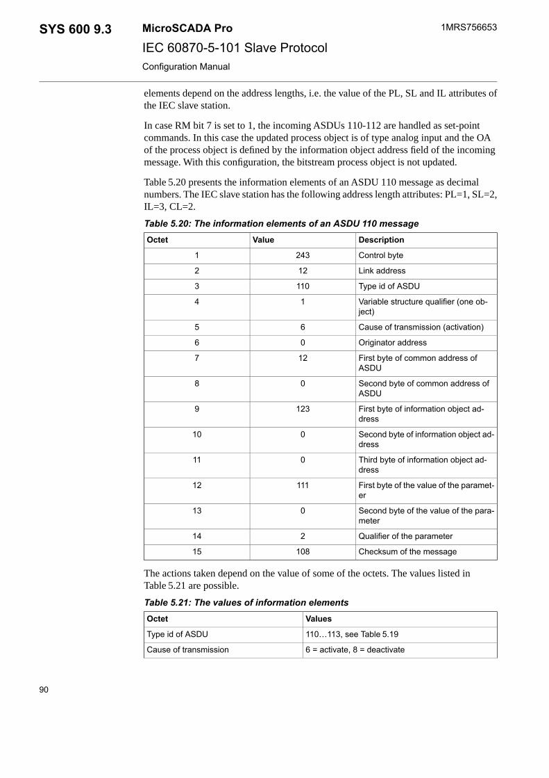
elements depend on the address lengths, i.e. the value of the PL, SL and IL attributes ofthe IEC slave station.
In case RM bit 7 is set to 1, the incoming ASDUs 110-112 are handled as set-pointcommands. In this case the updated process object is of type analog input and the OAof the process object is defined by the information object address field of the incomingmessage. With this configuration, the bitstream process object is not updated.
Table 5.20 presents the information elements of an ASDU 110 message as decimalnumbers. The IEC slave station has the following address length attributes: PL=1, SL=2,IL=3, CL=2.
Table 5.20: The information elements of an ASDU 110 messageDescriptionValueOctet
Control byte2431
Link address122
Type id of ASDU1103
Variable structure qualifier (one ob-ject)
14
Cause of transmission (activation)65
Originator address06
First byte of common address ofASDU
127
Second byte of common address ofASDU
08
First byte of information object ad-dress
1239
Second byte of information object ad-dress
010
Third byte of information object ad-dress
011
First byte of the value of the paramet-er
11112
Second byte of the value of the para-meter
013
Qualifier of the parameter214
Checksum of the message10815
The actions taken depend on the value of some of the octets. The values listed inTable 5.21 are possible.
Table 5.21: The values of information elementsValuesOctet
110…113, see Table 5.19Type id of ASDU
6 = activate, 8 = deactivateCause of transmission
90
1MRS756653MicroSCADA ProSYS 600 9.3IEC 60870-5-101 Slave ProtocolConfiguration Manual

ASDU 110: Parameter as normalised valueValue
ASDU 111: Parameter as scaled value
ASDU 112: Parameter as short floating point number
ASDU 113: Not included
ASDUs 110…112: 1=threshold value, 2=smoothingfactor, 3=low limit, 4=high limit
Qualifier
ASDU 113: 1=act/deact previously loaded paramet-ers, 2=act/deact of the addressed object, 3=act/deactcyclic transmission
5.7 Signal engineering
The term signal engineering here means the engineering needed for establishing thecommunication to NCC using IEC protocol. The signal engineering in COM 500i ismade using the signal X-reference tool after the system configuration is completed andthe process database for the related to process devices is ready. The signal engineeringprocess has been described in detail in COM 500i Users Guide manual of the SYS 600product. The principal sequence for the signal engineering is:
1. Make a list of all signals that are to be transferred between the master and the slave.Include at least the ASDU type, class and address.
2. Make sure that the same communication mode (balanced or unbalanced) is used inthe master and slave.
3. Determine the need for redundancy and update the system configurationcorrespondingly.
4. Define the NCCs, communication mode and the cross-reference data using the SignalX-references tool of COM 500i.
5. Test each signal.
5.8 Status codes
The following status codes are defined for the IEC 60870-5-101 Slave protocol. Sometypical reasons for some of the status codes are also given.
Status codes are sent as system messages, which can be received by analog input projectobjects with a unit number (UN) 0 and an object address (OA) as determined by the MIattribute of the line or station, or alternatively, they are returned as a response to a SCILcommand accessing a IEC station object.
Line layer status codes
For more information about the status codes, see Status Codes manual.
91
SYS 600 9.3MicroSCADA Pro
IEC 60870-5-101 Slave Protocol
1MRS756653
31.3.2010Issued:B/30.9.2012Version:
Configuration Manual

Station layer status codes
For more information about the status codes, see Status Codes manual.
5.9 Interoperability
5.9.1 Interoperability
This companion standard presents sets of parameters and alternatives from which subsetshave to be selected to implement particular telecontrol systems. Certain parameter values,such as the number of octets in the common address of ASDUs represent mutuallyexclusive alternatives. This means that only one value of the defined parameters isadmitted per system. Other parameters, such as the listed set of different processinformation in command and in monitor direction allow the specification of the completeset or subsets, as appropriate for the applications. This clause summarises the parametersof the previous clauses to facilitate a suitable selection for a specific application. If asystem is composed of equipment stemming from different manufacturers, it is necessarythat all the partners agree on the selected parameters.
The selected parameters should be marked in the white boxes as follows:
Function or ASDU is not used
Function or ASDU is used as standardized (default)
Function or ASDU is used in reverse mode
Function or ASDU is used in stardard and reverse mode
Function or ASDU may need some additional application level work
The possible selection (blank, X, R, or B) is specified for each specific clause orparameter.
In addition, the full specification of a system may requireindividual selection of certain parameters for certain parts ofthe system, such as the individual selection of scaling factorsfor individually addressable measured values.
5.9.1.1 System or device
(system-specific parameter)
System definition
Controlling station definition (Master)
92
1MRS756653MicroSCADA ProSYS 600 9.3IEC 60870-5-101 Slave ProtocolConfiguration Manual
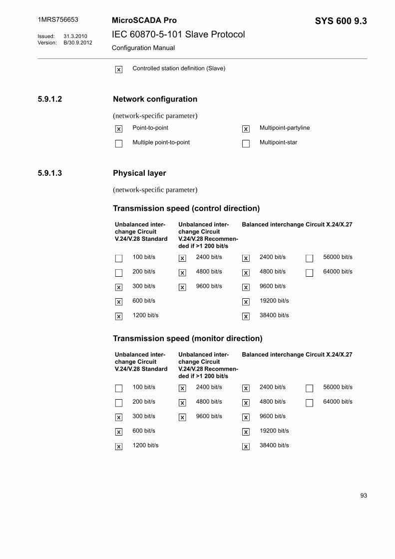
Controlled station definition (Slave)
5.9.1.2 Network configuration
(network-specific parameter)
Multipoint-partylinePoint-to-point
Multipoint-starMultiple point-to-point
5.9.1.3 Physical layer
(network-specific parameter)
Transmission speed (control direction)
Balanced interchange Circuit X.24/X.27Unbalanced inter-change CircuitV.24/V.28 Recommen-ded if >1 200 bit/s
Unbalanced inter-change CircuitV.24/V.28 Standard
56000 bit/s2400 bit/s2400 bit/s100 bit/s
64000 bit/s4800 bit/s4800 bit/s200 bit/s
9600 bit/s9600 bit/s300 bit/s
19200 bit/s600 bit/s
38400 bit/s1200 bit/s
Transmission speed (monitor direction)
Balanced interchange Circuit X.24/X.27Unbalanced inter-change CircuitV.24/V.28 Recommen-ded if >1 200 bit/s
Unbalanced inter-change CircuitV.24/V.28 Standard
56000 bit/s2400 bit/s2400 bit/s100 bit/s
64000 bit/s4800 bit/s4800 bit/s200 bit/s
9600 bit/s9600 bit/s300 bit/s
19200 bit/s600 bit/s
38400 bit/s1200 bit/s
93
SYS 600 9.3MicroSCADA Pro
IEC 60870-5-101 Slave Protocol
1MRS756653
31.3.2010Issued:B/30.9.2012Version:
Configuration Manual

5.9.1.4 Link layer
(network-specific parameter)
Frame format FT 1.2, single character 1 and the fixed time out interval are usedexclusively in this companion standard.
Address field of the linkLink transmission produce
Not present (balanced transmission only)Balanced transmission
One octetUnbalanced transmission
Two octetsFrame length
StructuredMaximum length L255
Unstructured
When using an unbalanced link layer, the following ASDU types are returned in class2 messages (low priority) with the indicated causes of transmission:
The standard assignment of ASDUs to class 2 messages is used as follows:
Cause of transmissionType identification
<1>9, 11, 13, 21
The standard assignment of ASDUs to class 2 messages is used as follows:
Cause of transmissionType identification
5.9.1.5 Application layer
Transmission mode for application data
Mode 1 (least significant octet first), as defined in 4.10 of IEC 60870-5-4, is usedexclusively in this companion standard.
Common address of ASDU
(system-specific parameter)
Two octetsOne octet
Information object address
(system-specific parameter)
StructuredOne octet
94
1MRS756653MicroSCADA ProSYS 600 9.3IEC 60870-5-101 Slave ProtocolConfiguration Manual

UnstructuredTwo octets
Three octets
Cause of transmission
(system-specific parameter)
Two octetsOne octet
Set to zero in case of no originator ad-dress
Selection of standard ASDUs
Process information in monitor direction
(station-specific parameter)
M_SP_NA_1<1> := Single-point information
M_SP_TA_1<2> := Single-point information with time tag
M_DP_NA_1<3> := Double-point information
M_DP_TA_1<4> := Double-point information with timetag
M_ST_NA_1<5> := Step position information
M_ST_TA_1<6> := Step position information with timetag
M_BO_NA_1<7> := Bitstring of 32 bit
M_BO_TA_1<8> := Bitstring of 32 bit with time tag
M_ME_NA_1<9> := Measured value, normalized value
M_ME_TA_1<10> := Measured value, normalized valuewith time tag
M_ME_NB_1<11> := Measured value, scaled value
M_ME_TB_1<12> := Measured value, scaled value withtime tag
M_ME_NC_1<13> := Measured value, short floating pointvalue
M_ME_TC_1<14> := Measured value, short floating pointvalue with time tag
M_IT_NA_1<15> := Integrated totals
M_IT_TA_1<16> := Integrated totals with time tag
M_EP_TA_1<17> := Event of protection equipment withtime tag
95
SYS 600 9.3MicroSCADA Pro
IEC 60870-5-101 Slave Protocol
1MRS756653
31.3.2010Issued:B/30.9.2012Version:
Configuration Manual

M_EP_TB_1<18> := Packed start events of protectionequipment with time tag
M_EP_TC_1<19> := Packed output circuit information ofprotection equipment with time tag
M_PS_NA_1<20> := Packed single-point information withstatus change detection
M_ME_ND_1<21> := Measured value, normalized valuewithout quality descriptor
M_SP_TB_1<30> := Single-point information with timetag CP56Time2a
M_DP_TB_1<31> := Double-point information with timetag CP56Time2a
M_ST_TB_1<32> := Step position information with timetag CP56Time2a
M_BO_TB_1<33> := Bitstring of 32 bit with time tagCP56Time2a
M_ME_TD_1<34> := Measured value, normalized valuewith time tag CP56Time2a
M_ME_TE_1<35> := Measured value, scaled value withtime tag CP56Time2a
M_ME_TF_1<36> := Measured value, short floating pointvalue with time tag CP56Time2a
M_IT_TB_1<37> := Integrated totals with time tagCP56Time2a
M_EP_TD_1<38> := Event of protection equipment withtime tag CP56Time2a
M_EP_TE_1<39> := Packed start events of protectionequipment with time tag CP56Time2a
M_EP_TF_1<40> := Packed output circuit information ofprotection equipment with time tagCP56Time2a
M_SR_NA_1<128> := Parameter byte string
M_SB_NA_1<130> := 101 Encapsulated SPA bus replymessage
Process information in control direction
(station-specific parameter)
C_SC_NA_1<45> := Single command
C_DC_NA_1<46> := Double command
C_RC_NA_1<47> := Regulating step command
C_SE_NA_1<48> := Set point command, normalizedvalue
96
1MRS756653MicroSCADA ProSYS 600 9.3IEC 60870-5-101 Slave ProtocolConfiguration Manual
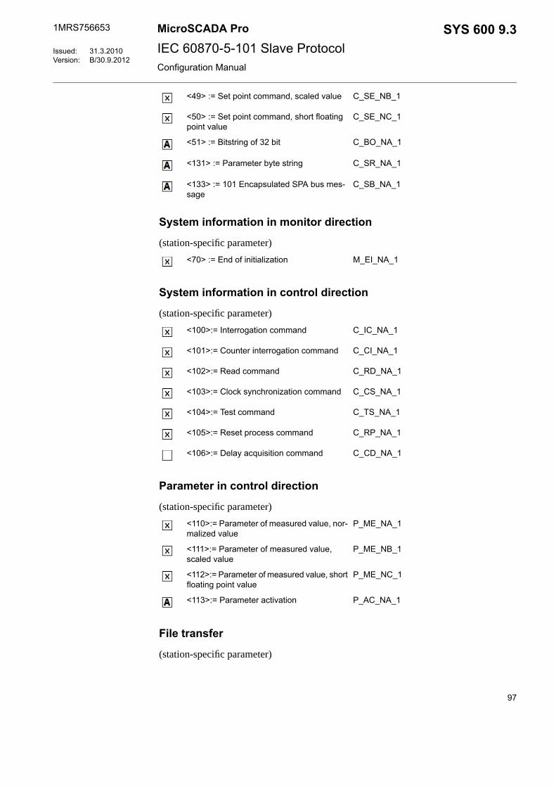
C_SE_NB_1<49> := Set point command, scaled value
C_SE_NC_1<50> := Set point command, short floatingpoint value
C_BO_NA_1<51> := Bitstring of 32 bit
C_SR_NA_1<131> := Parameter byte string
C_SB_NA_1<133> := 101 Encapsulated SPA bus mes-sage
System information in monitor direction
(station-specific parameter)
M_EI_NA_1<70> := End of initialization
System information in control direction
(station-specific parameter)
C_IC_NA_1<100>:= Interrogation command
C_CI_NA_1<101>:= Counter interrogation command
C_RD_NA_1<102>:= Read command
C_CS_NA_1<103>:= Clock synchronization command
C_TS_NA_1<104>:= Test command
C_RP_NA_1<105>:= Reset process command
C_CD_NA_1<106>:= Delay acquisition command
Parameter in control direction
(station-specific parameter)
P_ME_NA_1<110>:= Parameter of measured value, nor-malized value
P_ME_NB_1<111>:= Parameter of measured value,scaled value
P_ME_NC_1<112>:= Parameter of measured value, shortfloating point value
P_AC_NA_1<113>:= Parameter activation
File transfer
(station-specific parameter)
97
SYS 600 9.3MicroSCADA Pro
IEC 60870-5-101 Slave Protocol
1MRS756653
31.3.2010Issued:B/30.9.2012Version:
Configuration Manual

F_FR_NA_1<120>:= File ready
F_SR_NA_1<121>:= Section ready
F_SC_NA_1<122>:= Call directory, select file, call file,call section
F_LS_NA_1<123>:= Last section, last segment
F_AF_NA_1<124>:= Ack file, ack section
F_SG_NA_1<125>:= Segment
F_DR_TA_1<126>:= Directory {blank or X, only availablein monitor (standard) direction}
Type identifier and cause of transmission assignments
(station-specific parameters)
Shaded boxes are not required.Blank = function or ASDU is not used.Mark type identification/cause of transmission combinations:"X" if used only in the standard direction"R" if used only in the reverse direction"B" if used in both directions
Cause of transmissionType identification
4746454437to41
20to36
13121110987654321
M_SP_NA_1<1>
M_SP_TA_1<2>
M_DP_NA_1<3>
M_DP_TA_1<4>
M_ST_NA_1<5>
M_ST_TA_1<6>
M_BO_NA_1<7>
M_BO_TA_1<8>
M_ME_NA_1<9>
M_ME_TA_1<10>
M_ME_NB_1<11>
98
1MRS756653MicroSCADA ProSYS 600 9.3IEC 60870-5-101 Slave ProtocolConfiguration Manual

Cause of transmissionType identification
M_ME_TB_1<12>
M_ME_NC_1<13>
M_ME_TC_1<14>
M_IT_NA_1<15>
M_IT_TA_1<16>
M_EP_TA_1<17>
M_EP_TB_1<18>
M_EP_TC_1<19>
M_PS_NA_1<20>
M_ME_ND_1<21>
M_SP_TB_1<30>
M_DP_TB_1<31>
M_ST_TB_1<32>
M_BO_TB_1<33>
M_ME_TD_1<34>
M_ME_TE_1<35>
M_ME_TF_1<36>
M_IT_TB_1<37>
M_EP_TD_1<38>
M_EP_TE_1<39>
M_EP_TF_1<40>
C_SC_NA_1<45>
C_DC_NA_1<46>
C_RC_NA_1<47>
C_SE_NA_1<48>
C_SE_NB_1<49>
C_SE_NC_1<50>
99
SYS 600 9.3MicroSCADA Pro
IEC 60870-5-101 Slave Protocol
1MRS756653
31.3.2010Issued:B/30.9.2012Version:
Configuration Manual

Cause of transmissionType identification
C_BO_NA_1<51>
M_EI_NA_1<70>
C_IC_NA_1<100>
C_CI_NA_1<101>
C_RD_NA_1<102>
C_CS_NA_1<103>
C_TS_NA_1<104>
C_RP_NA_1<105>
C_CD_NA_1<106>
P_ME_NA_1<110>
P_ME_NB_1<111>
P_ME_NC_1<112>
P_AC_NA_1<113>
F_FR_NA_1<120>
F_SR_NA_1<121>
F_SC_NA_1<122>
F_LS_NA_1<123>
F_AF_NA_1<124>
F_SG_NA_1<125>
F_DR_TA_1*<126>
* Blank or X only.
5.9.1.6 Basic application functions
Station initialization
(station-specific parameter)
Remote initialization
100
1MRS756653MicroSCADA ProSYS 600 9.3IEC 60870-5-101 Slave ProtocolConfiguration Manual

Cyclic data transmission
(station-specific parameter)
Cyclic data transmission
Read procedure
(station-specific parameter)
Read procedure
Spontaneous transmission
(station-specific parameter)
Spontaneous transmission
Double transmission of information objects with cause oftransmission spontaneous
(station-specific parameter)
The following type identifications may be transmitted in succession caused by a singlestatus change of an information object. The particular information object addresses forwhich double transmission is enabled are defined in a project-specific list.
Single-point information M_SP_NA_1, M_SP_TA_1, M_SP_TB_1 and M_PS_NA_1
Double-point information M_DP_NA_1, M_DP_TA_1 and M_DP_TB_1
Step position information M_ST_NA_1, M_ST_TA_1 and M_ST_TB_1
Bitstring of 32 bit M_BO_NA_1, M_BO_TA_1 and M_BO_TB_1 (if defined for a specificproject, see 7.2.1.1????????)
Measured value, normalized value M_ME_NA_1, M_ME_TA_1, M_ME_ND_1 andM_ME_TD_1
Measured value, scaled value M_ME_NB_1, M_ME_TB_1 and M_ME_TE_1
Measured value, short floating point number M_ME_NC_1, M_ME_TC_1 and M_ME_TF_1
Station interrogation
(station-specific parameter)
global
group 13group 7group 1
group 14group 8group 2
101
SYS 600 9.3MicroSCADA Pro
IEC 60870-5-101 Slave Protocol
1MRS756653
31.3.2010Issued:B/30.9.2012Version:
Configuration Manual
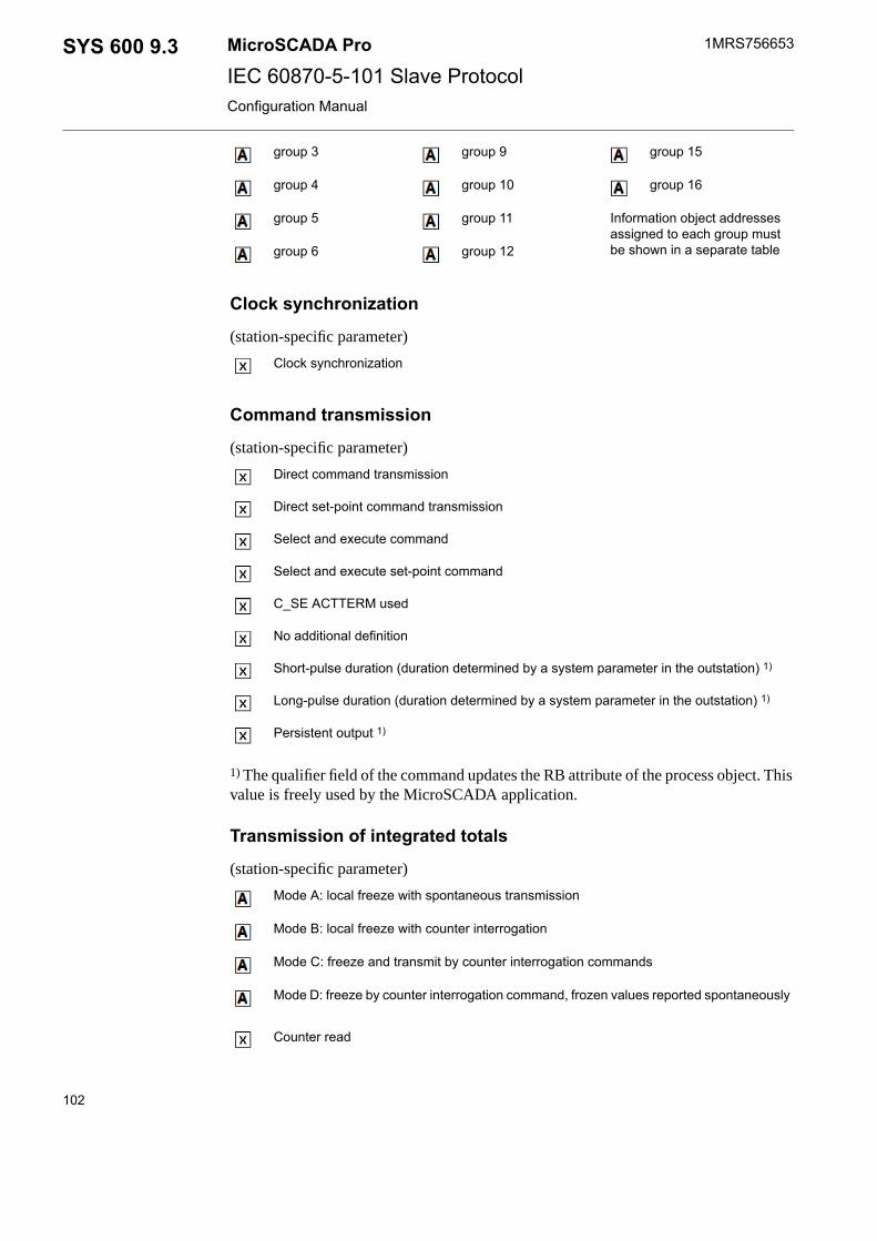
group 15group 9group 3
group 16group 10group 4
Information object addressesassigned to each group mustbe shown in a separate table
group 11group 5
group 12group 6
Clock synchronization
(station-specific parameter)
Clock synchronization
Command transmission
(station-specific parameter)
Direct command transmission
Direct set-point command transmission
Select and execute command
Select and execute set-point command
C_SE ACTTERM used
No additional definition
Short-pulse duration (duration determined by a system parameter in the outstation) 1)
Long-pulse duration (duration determined by a system parameter in the outstation) 1)
Persistent output 1)
1) The qualifier field of the command updates the RB attribute of the process object. Thisvalue is freely used by the MicroSCADA application.
Transmission of integrated totals
(station-specific parameter)
Mode A: local freeze with spontaneous transmission
Mode B: local freeze with counter interrogation
Mode C: freeze and transmit by counter interrogation commands
Mode D: freeze by counter interrogation command, frozen values reported spontaneously
Counter read
102
1MRS756653MicroSCADA ProSYS 600 9.3IEC 60870-5-101 Slave ProtocolConfiguration Manual

Counter freeze without reset
Counter freeze with reset
Counter reset
General request counter
Request counter group 1
Request counter group 2
Request counter group 3
Request counter group 4
Parameter loading
(station-specific parameter)
Threshold value
Smoothing factor
Low limit for transmission of measured value
High limit for transmission of measured value
Parameter activation
(station-specific parameter)
Act/deact of persistent cyclic or periodic transmission of the addressed object
Test procedure
(station-specific parameter)
Test procedure
File transfer
(station-specific parameter)
File transfer in monitor direction
Transparent file
Transmission of disturbance data of protection equipment
Transmission of sequences of events
103
SYS 600 9.3MicroSCADA Pro
IEC 60870-5-101 Slave Protocol
1MRS756653
31.3.2010Issued:B/30.9.2012Version:
Configuration Manual

Transmission of sequences of recorded analogue values
File transfer in control direction
Transparent file
Background scan
(station-specific parameter)
Background scan
Acquisition of transmission delay
(station-specific parameter)
Acquisition of transmission delay
104
1MRS756653MicroSCADA ProSYS 600 9.3IEC 60870-5-101 Slave ProtocolConfiguration Manual

Appendix A Examples of communication system configuration
The following SCIL procedures make the communication system configuration whichis related to the base system configuration example presented earlier in this document.The first procedure creates an IEC 60870-5-101 Slave line and two stations on this line.
;***************************************************************************
; INPUT PARAMETERS
@NET = 3 ; NODE NUMBER OF THE PC-NET
@MODE = 0 ; BALANCED MODE
@LINE = 1 ; LINE NUMBER
@STATIONS = (1,2) ; SLAVE STATION NUMBERS
@APPLIC = 1 ; APPLICATION NUMBER
;***************************************************************************
; CREATE A IEC 60870-5-101 LINE TO NET
#IF NET'NET':SPO'LINE'==0 #THEN #BLOCK
#IF %MODE==0 #THEN #BLOCK
#SET NET'NET':SPO'LINE' = 30 ;balanced IEC 60870-5-101
;slave
#SET NET'NET':SLK'LINE' = 12 ;link type
#SET NET'NET':SPD'LINE' = 5000;polling detection (ms)
#BLOCK_END
#ELSE_IF %MODE==1 #THEN #BLOCK
#SET NET'NET':SPO'LINE' = 29 ;unbalanced IEC 60870-5-101
;slave
#SET NET'NET':SLK'LINE' = 4 ;link type
#SET NET'NET':SPD'LINE' = 30000 ;polling detection (ms)
#BLOCK_END
#SET NET'NET':SSD'LINE' = "COM1" ;system device name
#SET NET'NET':SMS'LINE' = %APPLIC ;message application
#SET NET'NET':SMI'LINE' = %LINE+(6000+(%NET*100)) ;messageidentifier
#SET NET'NET':SBR'LINE' = 9600 ;baud rate
#SET NET'NET':SPY'LINE' = 2 ;parity
#SET NET'NET':SRD'LINE' = 8 ;receive bit count
#SET NET'NET':STD'LINE' = 8 ;transmit bit count
#SET NET'NET':SSB'LINE' = 1 ;stop bit count
#SET NET'NET':SPS'LINE' = 20 ;buffer pool size
#SET NET'NET':SDE'LINE' = 50 ;CTS delay (ms)
#SET NET'NET':STW'LINE' = 0 ;transmission wait delay (ms)
#SET NET'NET':SHT'LINE' = 2000 ;header timeout (ms)
#SET NET'NET':STI'LINE' = 2 ;timeout interval (s)
#SET NET'NET':SRK'LINE' = 0 ;RTS keep up padding
;characters
#SET NET'NET':SRI'LINE' = 0 ;receiver disabling time (ms)
#SET NET'NET':SEN'LINE' = 3 ;enquiry limit
105
SYS 600 9.3MicroSCADA Pro
IEC 60870-5-101 Slave Protocol
1MRS756653
31.3.2010Issued:B/30.9.2012Version:
Configuration Manual
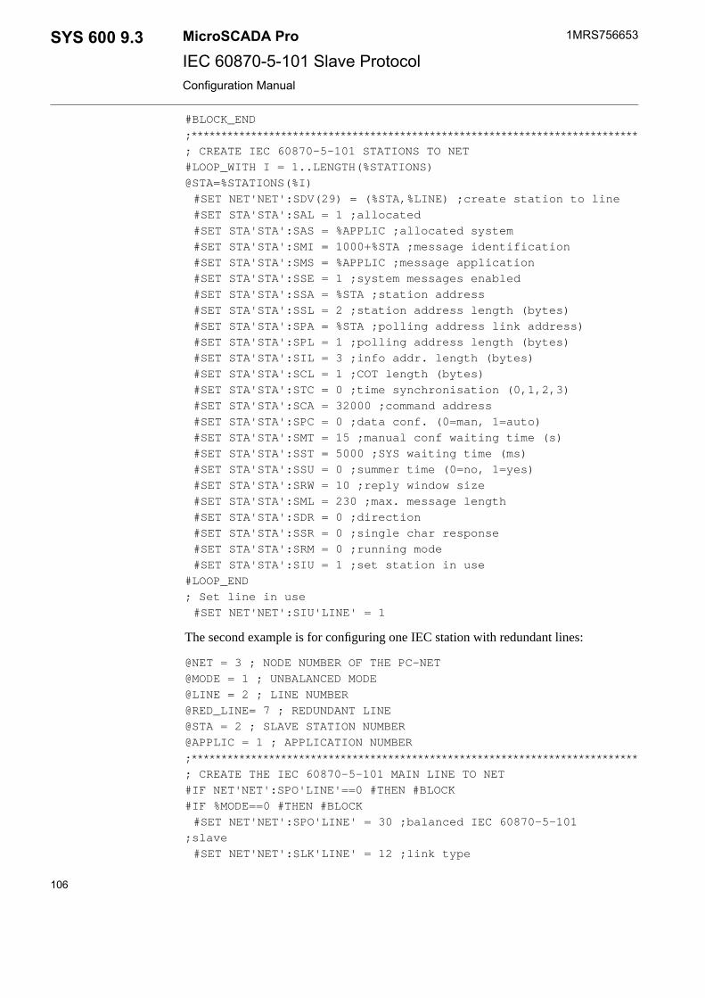
#BLOCK_END
;***************************************************************************
; CREATE IEC 60870-5-101 STATIONS TO NET
#LOOP_WITH I = 1..LENGTH(%STATIONS)
@STA=%STATIONS(%I)
#SET NET'NET':SDV(29) = (%STA,%LINE) ;create station to line
#SET STA'STA':SAL = 1 ;allocated
#SET STA'STA':SAS = %APPLIC ;allocated system
#SET STA'STA':SMI = 1000+%STA ;message identification
#SET STA'STA':SMS = %APPLIC ;message application
#SET STA'STA':SSE = 1 ;system messages enabled
#SET STA'STA':SSA = %STA ;station address
#SET STA'STA':SSL = 2 ;station address length (bytes)
#SET STA'STA':SPA = %STA ;polling address link address)
#SET STA'STA':SPL = 1 ;polling address length (bytes)
#SET STA'STA':SIL = 3 ;info addr. length (bytes)
#SET STA'STA':SCL = 1 ;COT length (bytes)
#SET STA'STA':STC = 0 ;time synchronisation (0,1,2,3)
#SET STA'STA':SCA = 32000 ;command address
#SET STA'STA':SPC = 0 ;data conf. (0=man, 1=auto)
#SET STA'STA':SMT = 15 ;manual conf waiting time (s)
#SET STA'STA':SST = 5000 ;SYS waiting time (ms)
#SET STA'STA':SSU = 0 ;summer time (0=no, 1=yes)
#SET STA'STA':SRW = 10 ;reply window size
#SET STA'STA':SML = 230 ;max. message length
#SET STA'STA':SDR = 0 ;direction
#SET STA'STA':SSR = 0 ;single char response
#SET STA'STA':SRM = 0 ;running mode
#SET STA'STA':SIU = 1 ;set station in use
#LOOP_END
; Set line in use
#SET NET'NET':SIU'LINE' = 1
The second example is for configuring one IEC station with redundant lines:
@NET = 3 ; NODE NUMBER OF THE PC-NET
@MODE = 1 ; UNBALANCED MODE
@LINE = 2 ; LINE NUMBER
@RED_LINE= 7 ; REDUNDANT LINE
@STA = 2 ; SLAVE STATION NUMBER
@APPLIC = 1 ; APPLICATION NUMBER
;***************************************************************************
; CREATE THE IEC 60870-5-101 MAIN LINE TO NET
#IF NET'NET':SPO'LINE'==0 #THEN #BLOCK
#IF %MODE==0 #THEN #BLOCK
#SET NET'NET':SPO'LINE' = 30 ;balanced IEC 60870-5-101
;slave
#SET NET'NET':SLK'LINE' = 12 ;link type
106
1MRS756653MicroSCADA ProSYS 600 9.3IEC 60870-5-101 Slave ProtocolConfiguration Manual

#SET NET'NET':SPD'LINE' = 5000;polling detection (ms)
#BLOCK_END
#ELSE_IF %MODE==1 #THEN #BLOCK
#SET NET'NET':SPO'LINE' = 29 ;unbalanced IEC 60870-5-101
;slave
#SET NET'NET':SLK'LINE' = 4 ;link type
#SET NET'NET':SPD'LINE' = 30000 ;polling detection (ms)
#BLOCK_END
#SET NET'NET':SSD'LINE' = "COM3" ;system device name
#SET NET'NET':SMS'LINE' = %APPLIC ;message application
#SET NET'NET':SMI'LINE' = %LINE+(6000+(%NET*100));messageidentifier
#SET NET'NET':SBR'LINE' = 9600 ;baud rate
#SET NET'NET':SPY'LINE' = 2 ;parity
#SET NET'NET':SRD'LINE' = 8 ;receive bit count
#SET NET'NET':STD'LINE' = 8 ;transmit bit count
#SET NET'NET':SSB'LINE' = 1 ;stop bit count
#SET NET'NET':SPS'LINE' = 20 ;buffer pool size
#SET NET'NET':SDE'LINE' = 50 ;CTS delay (ms)
#SET NET'NET':STW'LINE' = 0 ;transmission wait delay (ms)
#SET NET'NET':SHT'LINE' = 2000 ;header timeout (ms)
#SET NET'NET':STI'LINE' = 2 ;timeout interval (s)
#SET NET'NET':SRK'LINE' = 0 ;RTS keep up padding characters
#SET NET'NET':SRI'LINE' = 0 ;receiver disabling time (ms)
#SET NET'NET':SEN'LINE' = 3 ;enquiry limit
#SET NET'NET':SRU'LINE' = %STA ;redundant line station definition
#BLOCK_END
;***************************************************************************
; CREATE THE IEC 60870-5-101 BACK-UP LINE TO NET
#IF NET'NET':SPO'RED_LINE'==0 #THEN #BLOCK
#IF %MODE==0 #THEN #BLOCK
#SET NET'NET':SPO'RED_LINE' = 30 ;balanced IEC 60870-5-101
;slave
#SET NET'NET':SLK'RED_LINE' = 12 ;link type
#SET NET'NET':SPD'RED_LINE' = 5000 ;polling detection (ms)
#BLOCK_END
#ELSE_IF %MODE==1 #THEN #BLOCK
#SET NET'NET':SPO'RED_LINE' = 29 ;unbalanced IEC 60870-5-101
;slave
#SET NET'NET':SLK'RED_LINE' = 4 ;link type
#SET NET'NET':SPD'RED_LINE' = 30000 ;polling detection (ms)
#BLOCK_END
#SET NET'NET':SSD'RED_LINE' = "COM8" ;system device name
#SET NET'NET':SMS'RED_LINE' = %APPLIC ;message application
#SET NET'NET':SMI'RED_LINE' = %LINE+(6000+(%NET*100));message
;identifier
#SET NET'NET':SBR'RED_LINE' = 9600 ;baud rate
107
SYS 600 9.3MicroSCADA Pro
IEC 60870-5-101 Slave Protocol
1MRS756653
31.3.2010Issued:B/30.9.2012Version:
Configuration Manual

#SET NET'NET':SPY'RED_LINE' = 2 ;parity
#SET NET'NET':SRD'RED_LINE' = 8 ;receive bit count
#SET NET'NET':STD'RED_LINE' = 8 ;transmit bit count
#SET NET'NET':SSB'RED_LINE' = 1 ;stop bit count
#SET NET'NET':SPS'RED_LINE' = 20 ;buffer pool size
#SET NET'NET':SDE'RED_LINE' = 50 ;CTS delay (ms)
#SET NET'NET':STW'RED_LINE' = 0 ;transmission wait delay (ms)
#SET NET'NET':SHT'RED_LINE' = 2000 ;header timeout (ms)
#SET NET'NET':STI'RED_LINE' = 2 ;timeout interval (s)
#SET NET'NET':SRK'RED_LINE' = 0 ;RTS keep up padding
;characters
#SET NET'NET':SRI'RED_LINE' = 0 ;receiver disabling time (ms)
#SET NET'NET':SEN'RED_LINE' = 3 ;enquiry limit
#SET NET'NET':SRU'RED_LINE' = %STA ;redundant line station
;definition
#BLOCK_END
;***************************************************************************
; CREATE IEC 60870-5-101 SLAVE STATION TO NET
#SET NET'NET':SDV(29) = (%STA,%LINE) ;create station to line
#SET STA'STA':SLI(2) = %RED_LINE ;redundant line number
#SET STA'STA':SAL = 1 ;allocated
#SET STA'STA':SAS = %APPLIC ;allocated system
#SET STA'STA':SMI = 1000+%STA ;message identification
#SET STA'STA':SMS = %APPLIC ;message application
#SET STA'STA':SSE = 1 ;system messages enabled
#SET STA'STA':SSA = %STA ;station address
#SET STA'STA':SSL = 2 ;station address length (bytes)
#SET STA'STA':SPA = %STA ;polling address link address)
#SET STA'STA':SPL = 1 ;polling address length (bytes)
#SET STA'STA':SIL = 3 ;info addr. length (bytes)
#SET STA'STA':SCL = 2 ;COT length (bytes)
#SET STA'STA':STC = 0 ;time synchronisation (0,1,2,3)
#SET STA'STA':SCA = 32000 ;command address
#SET STA'STA':SPC = 0 ;data conf. (0=man, 1=auto)
#SET STA'STA':SMT = 15 ;manual conf waiting time (s)
#SET STA'STA':SST = 5000 ;SYS waiting time (ms)
#SET STA'STA':SSU = 0 ;summer time (0=no, 1=yes)
#SET STA'STA':SRW = 10 ;reply window size
#SET STA'STA':SML = 230 ;max. message length
#SET STA'STA':SDR = 0 ;direction
#SET STA'STA':SSR = 0 ;single char response
#SET STA'STA':SRM = 0 ;running mode
#SET STA'STA':SIU = 1 ;set station in use
; Set lines in use
#SET NET'NET':SIU'LINE' = 1
#SET NET'NET':SIU'RED_LINE' = 1
108
1MRS756653MicroSCADA ProSYS 600 9.3IEC 60870-5-101 Slave ProtocolConfiguration Manual

The third example is for an IEC 60870-5-101 slave line with dial-up and two IEC stations.
;***************************************************************************
; INPUT PARAMETERS
@NET = 3 ; NODE NUMBER OF THE PC-NET
@MODE = 1 ; 0 = BALANCED MODE, 1 = BALANCED MODE
@LINE = 2 ; LINE NUMBER
@STATIONS = (1,2) ; MASTER STATION NUMBERS
@APPLIC = 1 ; APPLICATION NUMBER
;***************************************************************************
; CREATE A IEC 60870-5-101 SLAVE DIAL-UP LINE TO NET
#IF NET'NET':SPO'LINE'==0 #THEN #BLOCK
#IF %MODE==0 #THEN #BLOCK
#SET NET'NET':SPO'LINE' = 32 ;balanced IEC 60870-5-101
;master
#SET NET'NET':SLK'LINE' = 12 ;link type
#SET NET'NET':SPD'LINE' = 5000;polling delay (ms)
#SET NET'NET':SRI'LINE' = 0 ;receiver disabling time (ms)
#BLOCK_END
#ELSE_IF %MODE==1 #THEN #BLOCK
#SET NET'NET':SPO'LINE' = 31 ;unbalanced IEC 60870-5-101
;master
#SET NET'NET':SLK'LINE' = 1 ;link type
#SET NET'NET':SPD'LINE' = 500 ;polling delay (ms)
#SET NET'NET':SRI'LINE' = 5 ;receiver disabling time (ms)
#SET NET'NET':SPL'LINE' = 10 ;polling limit
#BLOCK_END
#SET NET'NET':SPP'LINE' = 10 ;polling period(ms)
#SET NET'NET':SRP'LINE' = 1 ;reply polling
#SET NET'NET':SMS'LINE' = %APPLIC ;message application
#SET NET'NET':SMI'LINE' = %LINE+(6000+(%NET*100));messageidentifier
#SET NET'NET':SBR'LINE' = 9600 ;baud rate
#SET NET'NET':SPY'LINE' = 2 ;parity
#SET NET'NET':SRD'LINE' = 8 ;receive bit count
#SET NET'NET':STD'LINE' = 8 ;transmit bit count
#SET NET'NET':SSB'LINE' = 1 ;stop bit count
#SET NET'NET':SPS'LINE' = 20 ;buffer pool size
#SET NET'NET':SDE'LINE' = 50 ;CTS delay (ms)
#SET NET'NET':STW'LINE' = 0 ;transmission wait delay (ms)
#SET NET'NET':SHT'LINE' = 50 ;header timeout (ms)
#SET NET'NET':STI'LINE' = 50 ;timeout interval (ms)
#SET NET'NET':SRK'LINE' = 0 ;RTS keep up padding characters
#SET NET'NET':SEN'LINE' = 3 ;enquiry limit
#SET NET'NET':SAC'LINE' = 1 ;autocaller enabled
#SET NET'NET':SIU'LINE' = 1 ;set line in use, initialize modem
#BLOCK_END
109
SYS 600 9.3MicroSCADA Pro
IEC 60870-5-101 Slave Protocol
1MRS756653
31.3.2010Issued:B/30.9.2012Version:
Configuration Manual
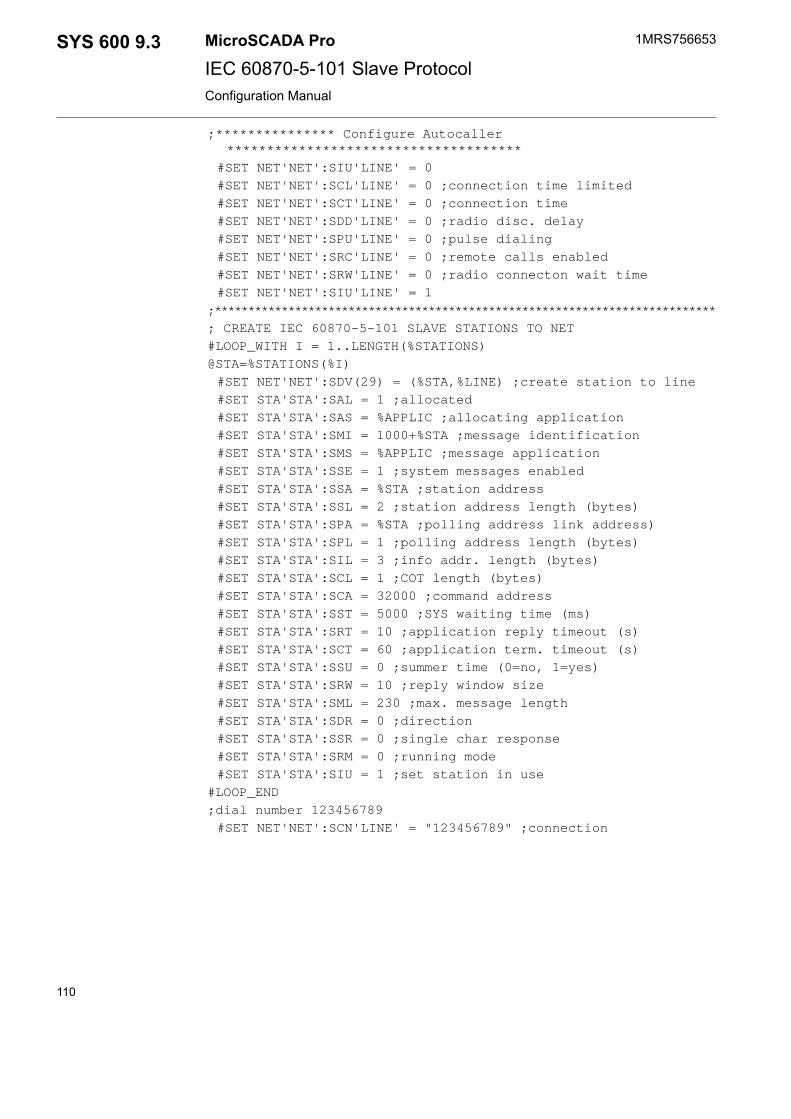
;*************** Configure Autocaller*************************************
#SET NET'NET':SIU'LINE' = 0
#SET NET'NET':SCL'LINE' = 0 ;connection time limited
#SET NET'NET':SCT'LINE' = 0 ;connection time
#SET NET'NET':SDD'LINE' = 0 ;radio disc. delay
#SET NET'NET':SPU'LINE' = 0 ;pulse dialing
#SET NET'NET':SRC'LINE' = 0 ;remote calls enabled
#SET NET'NET':SRW'LINE' = 0 ;radio connecton wait time
#SET NET'NET':SIU'LINE' = 1
;***************************************************************************
; CREATE IEC 60870-5-101 SLAVE STATIONS TO NET
#LOOP_WITH I = 1..LENGTH(%STATIONS)
@STA=%STATIONS(%I)
#SET NET'NET':SDV(29) = (%STA,%LINE) ;create station to line
#SET STA'STA':SAL = 1 ;allocated
#SET STA'STA':SAS = %APPLIC ;allocating application
#SET STA'STA':SMI = 1000+%STA ;message identification
#SET STA'STA':SMS = %APPLIC ;message application
#SET STA'STA':SSE = 1 ;system messages enabled
#SET STA'STA':SSA = %STA ;station address
#SET STA'STA':SSL = 2 ;station address length (bytes)
#SET STA'STA':SPA = %STA ;polling address link address)
#SET STA'STA':SPL = 1 ;polling address length (bytes)
#SET STA'STA':SIL = 3 ;info addr. length (bytes)
#SET STA'STA':SCL = 1 ;COT length (bytes)
#SET STA'STA':SCA = 32000 ;command address
#SET STA'STA':SST = 5000 ;SYS waiting time (ms)
#SET STA'STA':SRT = 10 ;application reply timeout (s)
#SET STA'STA':SCT = 60 ;application term. timeout (s)
#SET STA'STA':SSU = 0 ;summer time (0=no, 1=yes)
#SET STA'STA':SRW = 10 ;reply window size
#SET STA'STA':SML = 230 ;max. message length
#SET STA'STA':SDR = 0 ;direction
#SET STA'STA':SSR = 0 ;single char response
#SET STA'STA':SRM = 0 ;running mode
#SET STA'STA':SIU = 1 ;set station in use
#LOOP_END
;dial number 123456789
#SET NET'NET':SCN'LINE' = "123456789" ;connection
110
1MRS756653MicroSCADA ProSYS 600 9.3IEC 60870-5-101 Slave ProtocolConfiguration Manual

Index
AAA, 76AC, 38Addressing, 53AF, 76AI, 78AL, 25Allocating Application, 26Allocation, 25AN, 76Analog
Inputs, 69setpoints, 78
Analog Inputs, 69APDU, 16Application Backup, 9Application commands, 80Application Service Data Units (ASDUs), 24, 25, 51AS, 26, 38AT command, 38, 40, 41Autocaller AT S Register, 41Autocaller Enabled, 38Autocaller State, 38
BBackup copies, 9Balanced mode, 52Baud Rate, 16Bit Strings, 74BL, 59BR, 16Buffer Pool Size, 16
CCA, 27, 30, 59, 86Carrier Blocking, 21Cause of transmission (COT), 58, 61, 63, 80, 81, 90Cause of Transmission (COT), 25CB, 21CC, 35CD, 27CF, 29, 63, 75, 85CL, 25, 39CN, 39COM 500i, 67
CommandProcedures, 67Transaction, 75
Command Address, 27Command Confirmation, 63Command Control, 35Command Delay, 27Command procedures, 67Command transaction, 75Common address of ASDU, 53Configuration, 11ConFirmation Mode, 29Connected Station, 39Connection, 39Connection Time, 39Connection Time Limited, 39Counter interrogation, 83Cross-reference data, 68CS, 39CT, 29, 39, 80CTS, 18, 20CTS Delay, 18CTS signal, 18, 49CY, 59
DData commands, 76Data flow, 54DC, 21, 32DCD, 20DCD signal, 21, 41, 49DD, 40DE, 18Diagnostic Counters, 21, 32Digital Inputs, 72Double Indications, 71
EEA, 28EN, 19End of initialisation, 89Enhanced Protocol Architecture (EPA), 51Enquiry Limit, 19EV, 34, 55, 60, 69, 74Event buffer overflow Address, 28Event channel, 55, 68
111
SYS 600 9.3MicroSCADA Pro
IEC 60870-5-101 Slave Protocol
1MRS756653
31.3.2010Issued:B/30.9.2012Version:
Configuration Manual

Event Data with Time Stamp, 60eXecute Timeout, 29
FFatal error, 9FB, 43FD, 42FF, 43FI, 42File Bytes, 43File Directory, 42File Information, 42File Name, 44File Timeout, 43File Transmission Status, 43File Values, 46FN, 44FT, 43FV, 46FX, 68, 82FX attribute, 68
GGeneral interrogation, 81Group interrogation, 82
HHeader Timeout, 18HT, 18
IIEC 60870-5-101 master protocol, 6IEC 60870-5-101 slave protocol, 11IEC Slave
COM 500i, 67IL, 25, 68, 89Information Address Length, 25Information object address, 53Input data, 54Integrated link, 11Integrated totals, 73In Use, 15, 23Invalid Time, 30IU, 15, 23, 38IU attribute, 15, 23IV, 30, 59
LLength of Cause of Transmission Information, 25Level of implementation, 51LI, 24, 37Line Layer, 14Line Layer Attributes, 15Line Number, 24, 37Link Address, 53Link layer, 14Link Type, 20LK, 20
MMaximum Delayed Response Time, 34Maximum Message Length, 27MC, 40, 41Message Application, 20, 26Message Identification, 20, 26MI, 20, 26, 91ML, 27Modem Command, 40Modem Signal, 20MS, 20, 26MT, 34, 36Multi-drop network topology, 13, 53
NNCC, 67NET, 32, 53Network topologies, 13, 14No limitations, 13NT, 59
OOA, 80Object commands, 76Object Status, 33OF, 59OG, 80OM, 22Open Systems Interconnection, 51Open Systems Interconnection (OSI), 51Operating Mode, 22OR, 59OS, 33Output data, 55OV, 59, 79, 80
112
1MRS756653MicroSCADA ProSYS 600 9.3IEC 60870-5-101 Slave ProtocolConfiguration Manual

PPA, 24, 53Parameter in control direction, 89Parity, 16PC, 29, 40, 76, 51PD, 17Physical layer, 51PL, 25, 89PO, 15, 52Point-to-point network topology, 13Polling Address, 24Polling Address Length, 25Polling Delay, 17Process Data Confirmation, 29Process object types, 52Protocol, 15Protocol converter, 11, 53PS, 16PU, 40Pulse counters, 73Pulse Dialing, 40PY, 16
QQI, 33Queue Information , 33
RRA, 79, 80Radio Connection Wait Time, 41, 42Radio Disconnection Delay, 40RB, 79, 80, 82RC, 40RD, 16Read, conditional write, 13Read command, 84Read-only, 13Receive Interrupt Enable Delay, 19Receiver Data Bit Count, 16Redundant Line Station, 37Remote Calls Enabled, 40Reply Window Size, 36Reset Event Queues, 57, 66Reset process command, 85Response Timeout, 19RI, 19, 73RK, 19RM, 29, 30, 56, 86
RS, 57, 66, 85RTS, 18, 19RTS Keep up Padding Characters, 19RTS signal, 18RU, 37Running Mode, 30RW, 34, 36, 41
SSA, 24, 53SB, 17, 59SD, 15, 34, 55, 57, 69, 74SE, 26Select-execute timeout, 31Send Subdirectory, 48Serial cable, 50SG, 20Signal address, 53Signal Cross-Reference Tool, 67Signal rerouting, 67Signals, 67Single Char Response, 28Single Indications, 71SL, 25, 89SM, 87SPA messages, 56Spontaneous Data, 57SR, 28, 41SS, 48ST, 34STA objects, 23Station Address, 24, 53Station Address Length, 25Station attributes, 23Station object, 23Status
codes, 10Status codes, 91, 92
Line Layer, 91Station Layer, 91
Stop Bits, 17Structured address, 53STY object, 12SU, 36Substation Control System (SCS), 6Summer Time, 36SYS 600, 6SYS_BASCON.COM, 12
113
SYS 600 9.3MicroSCADA Pro
IEC 60870-5-101 Slave Protocol
1MRS756653
31.3.2010Issued:B/30.9.2012Version:
Configuration Manual

SystemBackup, 9Commands, 64, 86Messages, 20, 26, 91Objects, 11, 12, 13
System Device Name, 15System Messages Enabled, 26SYS Waiting Time, 34
TTC, 30TD, 17, 56, 87TI, 19Time Synchronization, 30Transmission Wait Delay, 18Transmitter Data Bit Count, 17Transparent data, 66Transparent Data, 56
Transparent SPA, 87, 88TW, 18TY, 79
UUN, 27, 77, 80, 91Unbalanced mode, 52Unstructured address, 53
WWiring, 50Write-only, 13
XXT, 29XT attribute, 29
114
1MRS756653MicroSCADA ProSYS 600 9.3IEC 60870-5-101 Slave ProtocolConfiguration Manual


Contact us
1MR
S75
6653
B
/30.
9.20
12 ©
Cop
yrig
ht 2
012
AB
B. A
ll rig
hts
rese
rved
.ABB OySubstation Automation ProductsP.O. Box 699FI-65101 Vaasa
FINLAND
Tel. +358 10 22 11
Fax. +358 10 224 1094
www.abb.com/substationautomation