Synthetic Seismogram Objectives Make Well Section Quality check and edit logs Create an Estimated...
24
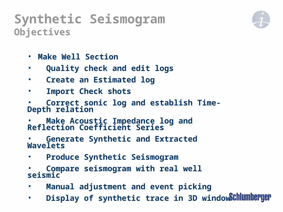
Synthetic Seismogram Objectives • Make Well Section • Quality check and edit logs • Create an Estimated log • Import Check shots • Correct sonic log and establish Time- Depth relation • Make Acoustic Impedance log and Reflection Coefficient Series • Generate Synthetic and Extracted Wavelets • Produce Synthetic Seismogram • Compare seismogram with real well seismic • Manual adjustment and event picking • Display of synthetic trace in 3D window
-
Upload
rolf-terry -
Category
Documents
-
view
226 -
download
3
Transcript of Synthetic Seismogram Objectives Make Well Section Quality check and edit logs Create an Estimated...
Synthetic SeismogramObjectives
• Make Well Section• Quality check and edit logs• Create an Estimated log• Import Check shots• Correct sonic log and establish Time-Depth relation• Make Acoustic Impedance log and Reflection Coefficient Series• Generate Synthetic and Extracted Wavelets• Produce Synthetic Seismogram• Compare seismogram with real well seismic • Manual adjustment and event picking• Display of synthetic trace in 3D window
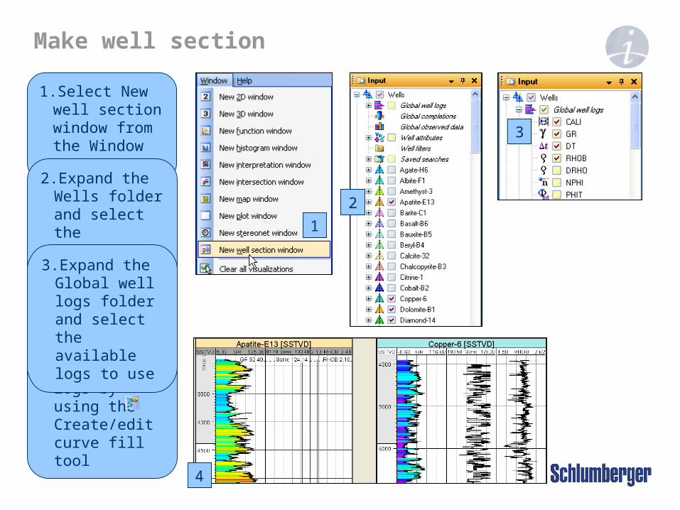
Make well section
1. Select New well section window from the Window menu
2. Expand the Wells folder and select the appropriate wells
1
2
4. Color fill logs by using the Create/edit curve fill tool
3
3. Expand the Global well logs folder and select the available logs to use
4
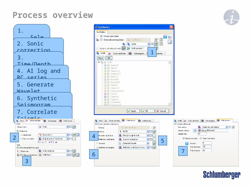
Process overview
1. Select wells
1
2. Sonic correction
3. Time/Depth lookup
4. AI log and RC series
5. Generate Wavelet
6. Synthetic Seismogram
7. Correlate Seismic
2
3
45
6 7
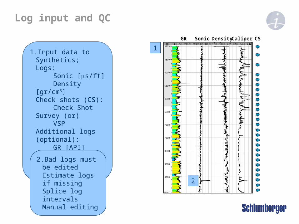
Log input and QC
1. Input data to Synthetics;Logs:
Sonic [s/ft]Density [gr/cm3]
Check shots (CS):Check Shot Survey
(or)VSP
Additional logs (optional):GR [API]Caliper [Hole
diameter]Any other
1
2
GR Sonic Density Caliper CS
2. Bad logs must be edited Estimate logs if missing Splice log intervals Manual editing

Log editing
1. From Global well logs Right click on DT and select Calculator
1 2
GR Sonic
5
4
2. Make expression Sonic_despiked=DT
3. Use sonic as template4. Sample MD from log
and select DT as input5. Click Enter
3
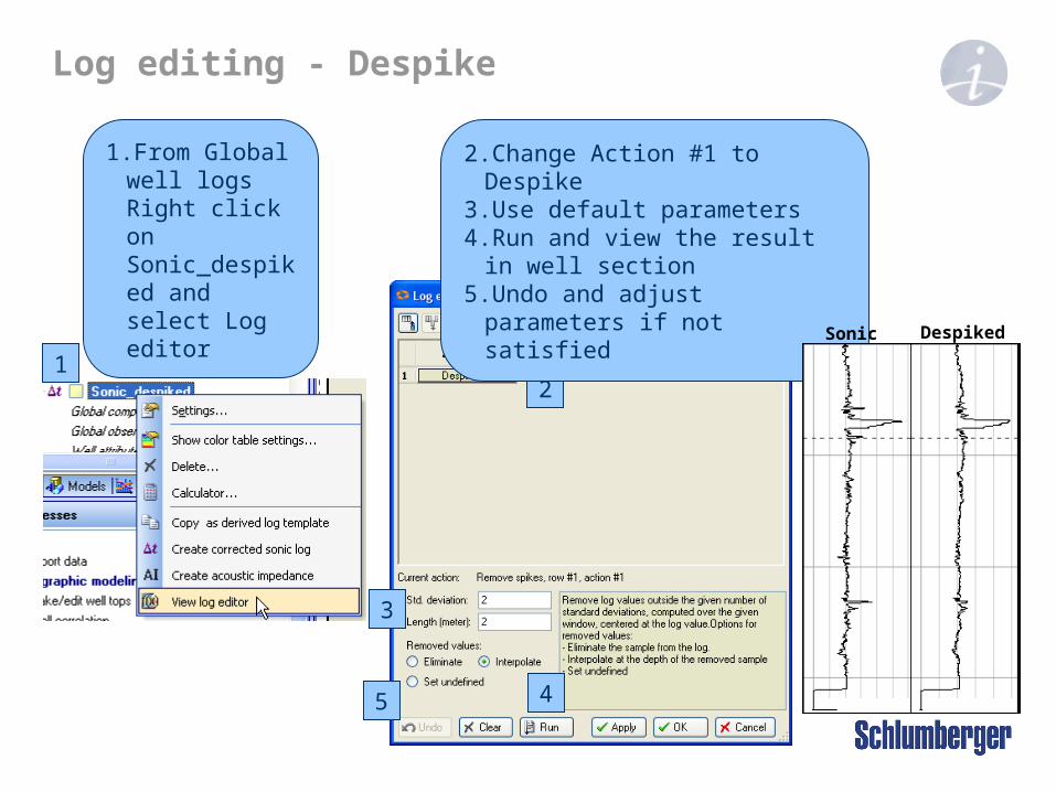
Log editing - Despike
12
3
45
2. Change Action #1 to Despike3. Use default parameters4. Run and view the result in well section5. Undo and adjust parameters if not satisfied
1. From Global well logs Right click on Sonic_despiked and select Log editor
Sonic Despiked
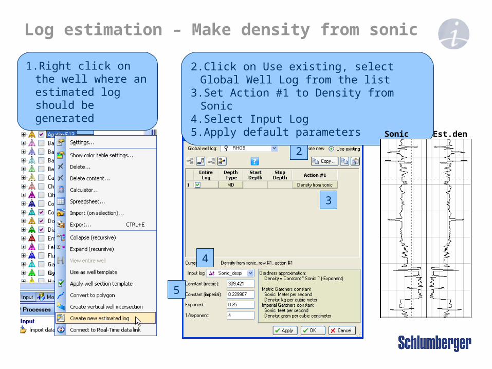
Log estimation – Make density from sonic
1
2
3
4
5
2. Click on Use existing, select Global Well Log from the list3. Set Action #1 to Density from Sonic4. Select Input Log5. Apply default parameters
1. Right click on the well where an estimated log should be generated
Sonic Est.density

1. Double click on the Synthetics process under Stratigraphic modeling
Process diagram
2
2. Move the mouse over each of the different icons to see hints on how to use them
1
Opens settings page for the object
Create a new object
Opens the spreadsheet for the object
3. Select wells to work with and a well section to display any results in
3
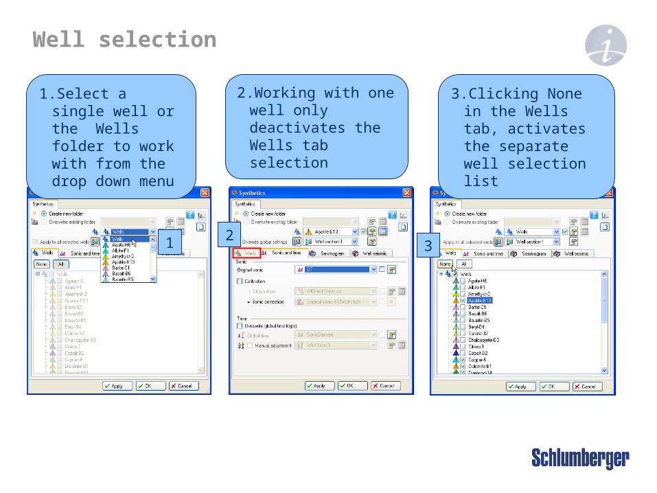
1. Select a single well or the Wells folder to work with from the drop down menu
Well selection
2
2. Working with one well only deactivates the Wells tab selection
3. Clicking None in the Wells tab, activates the separate well selection list
31

Load checkshots
1
2
3
4
3. Make sure Files of type is correct1. Right click on Wells folder and use Import (on selection)…
2. Select file(s) to import4. Access the files by clicking Open

Load checkshots
1
2
3
B
5. Right click on checkshots to open the spreadsheet1. Fit input parameters (A) to file (B)
A
5
4
6
2. Connect to welltrace
3. Correct data (if needed)
4. OK (one file) or OK For All (two or more files if in same format)
6. Change depth from MD to TVD. Compare TVD and TWT with input file(s) and other time/depth information

Sonic correction
1. Do the Sonic correction based on original sonic and check shots
Depth
Time
Check Shot Survey Sonic Log T.D.R.
2. Use the generated corrected sonic as input in the process
1
2
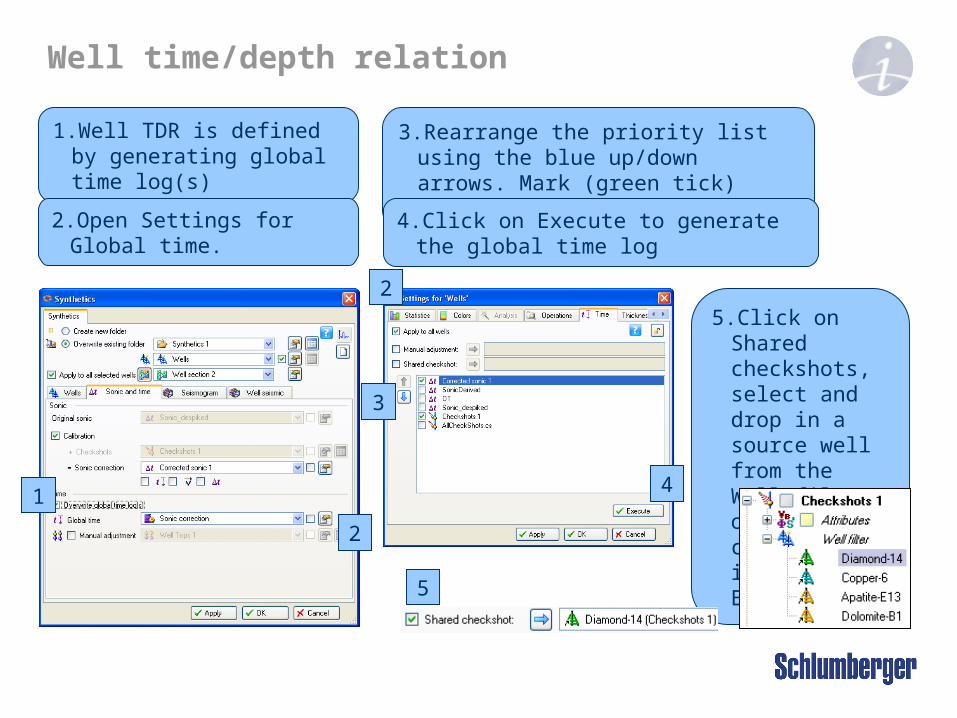
Well time/depth relation
1
2
1. Well TDR is defined by generating global time log(s)
5. Click on Shared checkshots, select and drop in a source well from the Well filter of a checkshots item. Execute
3
5
4
2. Open Settings for Global time.
3. Rearrange the priority list using the blue up/down arrows. Mark (green tick) objects to select from
4. Click on Execute to generate the global time log
2

1. In the Seismogram tab, click on Create synthetic seismogram
Acoustic impedance and Reflection coefficient series
6
2. Select Density to use
3. Click on create new object icon to generate an Acoustic impedance log. Settings opens for selection
4. Select density and sonic log onput
5. From the Acoustic impedance pull down menu, select the newly created log
6. Click on the Create new object icon for Reflection Coefficients. Select AI log for input and use the new log as input for RC
1
23
5
4
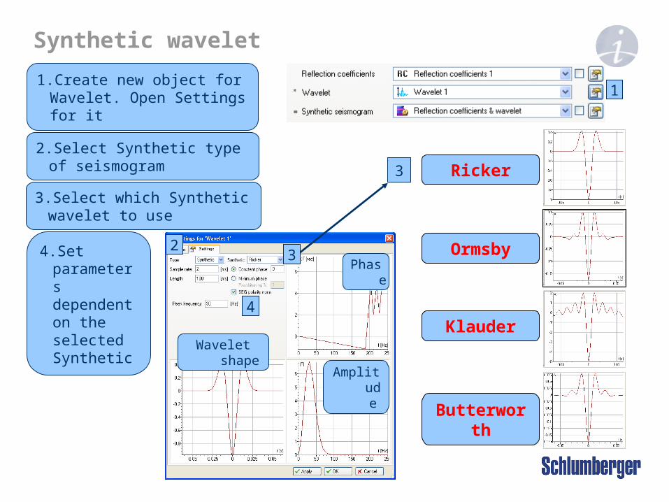
2. Select Synthetic type of seismogram
Synthetic wavelet
2
Wavelet shape
Phase
Amplitude
Ricker
Ormsby
Klauder
Butterworth
4
3
3
1. Create new object for Wavelet. Open Settings for it
3. Select which Synthetic wavelet to use
4. Set parameters dependent on the selected Synthetic
1

Extracted wavelet
1
Wavelet shape
Phase
Amplitude
3a
4
2
Bartlett
Papoulis
Hamming
Cosine
Hanning
4
5. Alternative type of seismogram is loaded from file
5
7
6
3b
1. Select Extracted type of seismogram
3. a) Set Neighborhood extent for 3D seismic b) If 2D lines are used, set number of traces
2. From Input pane, select seismic data and Well. Drop both ino the dialog box using the drop in arrows
4. Select Taper window type
6. Import the file in the Input pane and open it in the dialog box
7. Set Time unit

1. Click on the Synthetic seismogram pull down menu to view its content
Synthetic seismogram
2
1
Signal:
S=R*Wavelet
* =
2. Reflection coefficients and wavelet is input when Apply or OK is clicked

3. a) Select which extraction method to use, Radial or Orbital (3D) b) Set number of traces to use along seismic line (2D)
Well seismic extraction
1
4
3a
3b
2. From the input pane, click on the seismic data object and drop it in using the drop in arrow
1. In the Well seismic tab, check the Create well seismic box
4. Set appropiate parameters for method chosen.
2
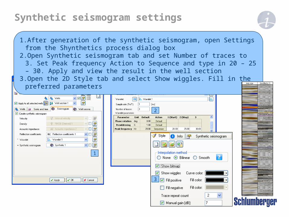
1. After generation of the synthetic seismogram, open Settings from the Shynthetics process dialog box
2. Open Synthetic seismogram tab and set Number of traces to 3. Set Peak frequency Action to Sequence and type in 20 – 25 – 30. Apply and view the result in the well section
3. Open the 2D Style tab and select Show wiggles. Fill in the preferred parameters
Synthetic seismogram settings
1
3
2

1. From the Input pane, right click on the Synthetics folder and select spreadsheet2. Filter on a single well and set the Domain to work in (e.g. TWT)3. Specify Step and Use limit Min. and Max. to filter the spreadsheet
Synthetic seismogram spreadsheet
1
32
4. Color fill the spreadsheet for visual aid to identify features not easily seen
4

1. Under the Sonic and time tab, with Overide global time log(s) active, check the Manual adjustment box
Manual adjustment
1
3
2
4
2. Open the Well tops spreadsheet
3. Updated TWT Picked values can be entered. Click Apply in the spreadsheet to store the manually entered values
4. Applying the manual adjustment in the Synthetics process will update the TWT auto values to fit the TWT picked values
Manual adjustment
5
6
7
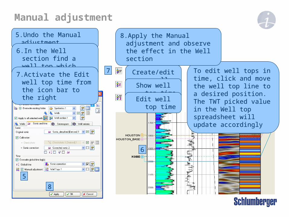
5. Undo the Manual adjustment
Create/edit well tops
Show well top time
Edit well top time
8
To edit well tops in time, click and move the well top line to a desired position. The TWT picked value in the Well top spreadsheet will update accordingly
6. In the Well section find a well top which needs adjustment
7. Activate the Edit well top time from the icon bar to the right
8. Apply the Manual adjustment and observe the effect in the Well section
3D display
2
3
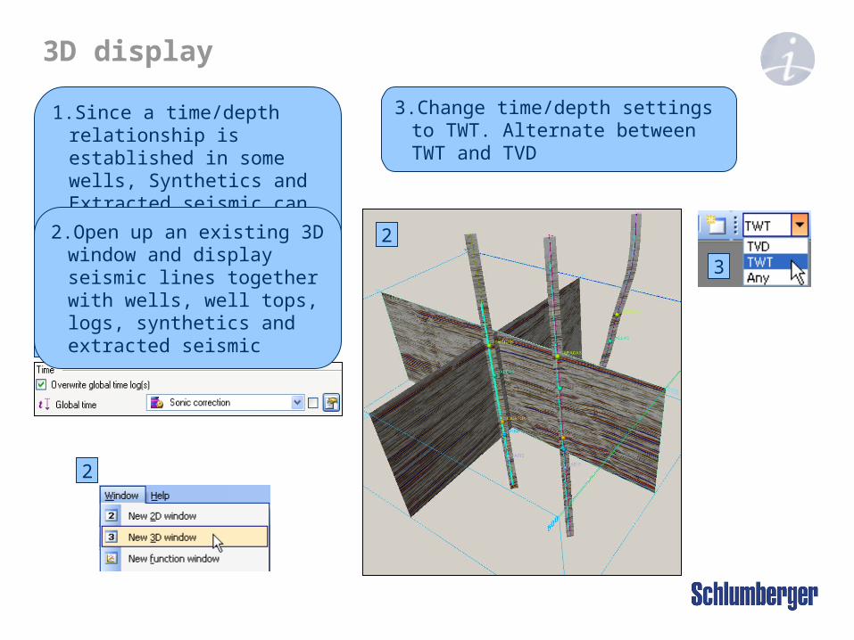
1. Since a time/depth relationship is established in some wells, Synthetics and Extracted seismic can be displayed in both time and depth
2
1
2. Open up an existing 3D window and display seismic lines together with wells, well tops, logs, synthetics and extracted seismic
3. Change time/depth settings to TWT. Alternate between TWT and TVD

EXERCISE Synthetic Seismogram