Synthetic Fiber Ropesfor Offshore Mooring
66
Recommended Practice for Design, Manufacture, Installation, and Maintenance of Synthetic Fiber Ropes for Offshore Mooring API RECOMMENDED PRACTICE 2SM FIRST EDITION, MARCH 2001
-
Upload
yongwei-jin -
Category
Documents
-
view
121 -
download
6
Transcript of Synthetic Fiber Ropesfor Offshore Mooring

Recommended Practice for Design, Manufacture, Installation, and Maintenance of Synthetic Fiber Ropes for Offshore Mooring
API RECOMMENDED PRACTICE 2SMFIRST EDITION, MARCH 2001


Recommended Practice for Design, Manufacture, Installation, and Maintenance of Synthetic Fiber Ropes for Offshore Mooring
Upstream Segment
API RECOMMENDED PRACTICE 2SMFIRST EDITION, MARCH 2001

SPECIAL NOTES
API publications necessarily address problems of a general nature. With respect to partic-ular circumstances, local, state, and federal laws and regulations should be reviewed.
API is not undertaking to meet the duties of employers, manufacturers, or suppliers towarn and properly train and equip their employees, and others exposed, concerning healthand safety risks and precautions, nor undertaking their obligations under local, state, or fed-eral laws.
Information concerning safety and health risks and proper precautions with respect to par-ticular materials and conditions should be obtained from the employer, the manufacturer orsupplier of that material, or the material safety data sheet.
Nothing contained in any API publication is to be construed as granting any right, byimplication or otherwise, for the manufacture, sale, or use of any method, apparatus, or prod-uct covered by letters patent. Neither should anything contained in the publication be con-strued as insuring anyone against liability for infringement of letters patent.
Generally, API standards are reviewed and revised, reafÞrmed, or withdrawn at least everyÞve years. Sometimes a one-time extension of up to two years will be added to this reviewcycle. This publication will no longer be in effect Þve years after its publication date as anoperative API standard or, where an extension has been granted, upon republication. Statusof the publication can be ascertained from the API Upstream Segment [telephone (202) 682-8000]. A catalog of API publications and materials is published annually and updated quar-terly by API, 1220 L Street, N.W., Washington, D.C. 20005.
This document was produced under API standardization procedures that ensure appropri-ate notiÞcation and participation in the developmental process and is designated as an APIstandard. Questions concerning the interpretation of the content of this standard or com-ments and questions concerning the procedures under which this standard was developedshould be directed in writing to the standardization manager of the Upstream Segment,American Petroleum Institute, 1220 L Street, N.W., Washington, D.C. 20005. Requests forpermission to reproduce or translate all or any part of the material published herein shouldalso be addressed to the standardization manager.
API standards are published to facilitate the broad availability of proven, sound engineer-ing and operating practices. These standards are not intended to obviate the need for apply-ing sound engineering judgment regarding when and where these standards should beutilized. The formulation and publication of API standards is not intended in any way toinhibit anyone from using any other practices.
Any manufacturer marking equipment or materials in conformance with the markingrequirements of an API standard is solely responsible for complying with all the applicablerequirements of that standard. API does not represent, warrant, or guarantee that such prod-ucts do in fact conform to the applicable API standard.
All rights reserved. No part of this work may be reproduced, stored in a retrieval system, or transmitted by any means, electronic, mechanical, photocopying, recording, or otherwise,
without prior written permission from the publisher. Contact the Publisher, API Publishing Services, 1220 L Street, N.W., Washington, D.C. 20005.
Copyright © 2001 American Petroleum Institute

FOREWORD
The main purpose of this document is to provide guidelines on the use of synthetic Þberropes for offshore mooring applications. The secondary purpose of this document is to high-light differences between synthetic rope and traditional steel mooring systems, and to pro-vide practical guidance on how to handle these differences during system design andinstallation.
Thus this document covers the following:
a. Design and analysis considerations of mooring system.b. Design criteria for mooring components.c. Rope design.d. Rope speciÞcation and testing.e. Rope manufacture and quality assurance.f. Rope handling and installation.g. In-service inspection and maintenance.
API RP 2SM is under the jurisdiction of the API Subcommittee on Offshore Structures.API publications may be used by anyone desiring to do so. Every effort has been made by
the Institute to assure the accuracy and reliability of the data contained in them; however, theInstitute makes no representation, warranty, or guarantee in connection with this publicationand hereby expressly disclaims any liability or responsibility for loss or damage resultingfrom its use or for the violation of any federal, state, or municipal regulation with which thispublication may conßict.
Suggested revisions are invited and should be submitted to the standardization manager ofthe Upstream Segment, American Petroleum Institute, 1220 L Street, N.W., Washington,D.C. 20005.
iii


CONTENTS
Page
1 SCOPE . . . . . . . . . . . . . . . . . . . . . . . . . . . . . . . . . . . . . . . . . . . . . . . . . . . . . . . . . . . . . . . 1
2 DEFINITIONS. . . . . . . . . . . . . . . . . . . . . . . . . . . . . . . . . . . . . . . . . . . . . . . . . . . . . . . . . 1
3 BASIC CONSIDERATIONS . . . . . . . . . . . . . . . . . . . . . . . . . . . . . . . . . . . . . . . . . . . . . 33.1 General . . . . . . . . . . . . . . . . . . . . . . . . . . . . . . . . . . . . . . . . . . . . . . . . . . . . . . . . . . 33.2 Synthetic Ropes for Offshore Mooring . . . . . . . . . . . . . . . . . . . . . . . . . . . . . . . . . 33.3 Main Characteristics of Synthetic Fiber Ropes. . . . . . . . . . . . . . . . . . . . . . . . . . . 4
4 ROPE DESIGN AND PROPERTIES . . . . . . . . . . . . . . . . . . . . . . . . . . . . . . . . . . . . . . 54.1 General . . . . . . . . . . . . . . . . . . . . . . . . . . . . . . . . . . . . . . . . . . . . . . . . . . . . . . . . . . 54.2 Rope Material. . . . . . . . . . . . . . . . . . . . . . . . . . . . . . . . . . . . . . . . . . . . . . . . . . . . . 54.3 Rope Construction . . . . . . . . . . . . . . . . . . . . . . . . . . . . . . . . . . . . . . . . . . . . . . . . . 54.4 Rope Jacket . . . . . . . . . . . . . . . . . . . . . . . . . . . . . . . . . . . . . . . . . . . . . . . . . . . . . . 64.5 Rope Termination. . . . . . . . . . . . . . . . . . . . . . . . . . . . . . . . . . . . . . . . . . . . . . . . . . 64.6 Rope Assembly Properties. . . . . . . . . . . . . . . . . . . . . . . . . . . . . . . . . . . . . . . . . . . 7
5 MOORING DESIGN AND ANALYSIS . . . . . . . . . . . . . . . . . . . . . . . . . . . . . . . . . . . 145.1 General . . . . . . . . . . . . . . . . . . . . . . . . . . . . . . . . . . . . . . . . . . . . . . . . . . . . . . . . . 145.2 Mooring ConÞguration . . . . . . . . . . . . . . . . . . . . . . . . . . . . . . . . . . . . . . . . . . . . 145.3 Design Criteria . . . . . . . . . . . . . . . . . . . . . . . . . . . . . . . . . . . . . . . . . . . . . . . . . . . 145.4 Mooring Analysis. . . . . . . . . . . . . . . . . . . . . . . . . . . . . . . . . . . . . . . . . . . . . . . . . 145.5 Model Testing . . . . . . . . . . . . . . . . . . . . . . . . . . . . . . . . . . . . . . . . . . . . . . . . . . . 16
6 ROPE SPECIFICATION AND TESTING . . . . . . . . . . . . . . . . . . . . . . . . . . . . . . . . . 166.1 General . . . . . . . . . . . . . . . . . . . . . . . . . . . . . . . . . . . . . . . . . . . . . . . . . . . . . . . . . 166.2 Rope SpeciÞcation . . . . . . . . . . . . . . . . . . . . . . . . . . . . . . . . . . . . . . . . . . . . . . . . 166.3 Rope Testing. . . . . . . . . . . . . . . . . . . . . . . . . . . . . . . . . . . . . . . . . . . . . . . . . . . . . 19
7 ROPE MANUFACTURE, INSPECTION, AND QUALITY ASSURANCE . . . . . . 217.1 General . . . . . . . . . . . . . . . . . . . . . . . . . . . . . . . . . . . . . . . . . . . . . . . . . . . . . . . . . 217.2 Rope Fiber Material . . . . . . . . . . . . . . . . . . . . . . . . . . . . . . . . . . . . . . . . . . . . . . . 217.3 Rope Manufacturing . . . . . . . . . . . . . . . . . . . . . . . . . . . . . . . . . . . . . . . . . . . . . . 227.4 Termination . . . . . . . . . . . . . . . . . . . . . . . . . . . . . . . . . . . . . . . . . . . . . . . . . . . . . 227.5 Assembly . . . . . . . . . . . . . . . . . . . . . . . . . . . . . . . . . . . . . . . . . . . . . . . . . . . . . . . 227.6 Inspection . . . . . . . . . . . . . . . . . . . . . . . . . . . . . . . . . . . . . . . . . . . . . . . . . . . . . . . 237.7 Quality Control and Assurance . . . . . . . . . . . . . . . . . . . . . . . . . . . . . . . . . . . . . . 24
8 ROPE HANDLING AND INSTALLATION . . . . . . . . . . . . . . . . . . . . . . . . . . . . . . . 248.1 General . . . . . . . . . . . . . . . . . . . . . . . . . . . . . . . . . . . . . . . . . . . . . . . . . . . . . . . . . 248.2 General Storage, Handling and Installation Considerations. . . . . . . . . . . . . . . . 248.3 Installation Design Considerations. . . . . . . . . . . . . . . . . . . . . . . . . . . . . . . . . . . . 268.4 Installation/ Recovery Procedures . . . . . . . . . . . . . . . . . . . . . . . . . . . . . . . . . . . . 28
9 IN-SERVICE INSPECTION AND MAINTENANCE . . . . . . . . . . . . . . . . . . . . . . . . 309.1 General309.2 Inspection and Testing Techniques . . . . . . . . . . . . . . . . . . . . . . . . . . . . . . . . . . . 309.3 Fiber Rope Inspection Procedure . . . . . . . . . . . . . . . . . . . . . . . . . . . . . . . . . . . . 319.4 Rope Retirement Criteria. . . . . . . . . . . . . . . . . . . . . . . . . . . . . . . . . . . . . . . . . . . 329.5 Maintenance Procedures For Permanent Moorings . . . . . . . . . . . . . . . . . . . . . . 33
v
Page
10 DESIGN EXAMPLES . . . . . . . . . . . . . . . . . . . . . . . . . . . . . . . . . . . . . . . . . . . . . . . . . 3310.1 General . . . . . . . . . . . . . . . . . . . . . . . . . . . . . . . . . . . . . . . . . . . . . . . . . . . . . . . . 3310.2 Mooring System Description . . . . . . . . . . . . . . . . . . . . . . . . . . . . . . . . . . . . . . . 3310.3 Extreme Response Analysis Example . . . . . . . . . . . . . . . . . . . . . . . . . . . . . . . . 3510.4 Fatigue Analysis Example . . . . . . . . . . . . . . . . . . . . . . . . . . . . . . . . . . . . . . . . . 39
APPENDIX AÑTESTING OF ROPE WET STRENGTH . . . . . . . . . . . . . . . . . . . . . . . . 41
APPENDIX BÑTESTING OF ROPE ELONGATION AND MODULUS . . . . . . . . . . . 43
APPENDIX CÑTESTING OF ROPE TENSION-TENSION FATIGUEQUALIFICATION . . . . . . . . . . . . . . . . . . . . . . . . . . . . . . . . . . . . . . . . . . 47
APPENDIX DÑTESTING OF ROPE AXIAL COMPRESSION PERFORMANCE . . . 49
APPENDIX EÑCOMMENTARY ON MARINE FINISH . . . . . . . . . . . . . . . . . . . . . . . . 51
APPENDIX FÑREFERENCES . . . . . . . . . . . . . . . . . . . . . . . . . . . . . . . . . . . . . . . . . . . . . 53
Tables4.6.2 Typical Rope Weights and Sizes for 10,000 kN (1,000 tonne) Break Strength 74.6.4.2 Typical Secant Stiffness Values . . . . . . . . . . . . . . . . . . . . . . . . . . . . . . . . . . . . . . 4.6.7.3 Axial Compression Fatigue in Yarn Buckling Tests. . . . . . . . . . . . . . . . . . . . . 126.3.6 Fiber Rope Fatigue QualiÞcation Test SpeciÞcation . . . . . . . . . . . . . . . . . . . . . . 8.2.1 Resistance to Chemical and UV Weakening . . . . . . . . . . . . . . . . . . . . . . . . . . 2410.3.3 Fairlead Motion Complex RAO . . . . . . . . . . . . . . . . . . . . . . . . . . . . . . . . . . . . 3710.3.4.1 Maximum Tensions of No. 11 Mooring Line. . . . . . . . . . . . . . . . . . . . . . . . . . 3710.3.5 Calculation of Number of Cycles . . . . . . . . . . . . . . . . . . . . . . . . . . . . . . . . . . . 3810.4.1 Environmental Condition, Mean Loads and Low-frequency Motions
for the Analyzed Direction . . . . . . . . . . . . . . . . . . . . . . . . . . . . . . . . . . . . . . . . 3810.4.2 Polyester Rope Segment Fatigue Damage . . . . . . . . . . . . . . . . . . . . . . . . . . . . 40
Figures4.6.4a Typical Elastic Properties for Polyester Fibers. . . . . . . . . . . . . . . . . . . . . . . . . . 84.6.4b Typical Elastic Properties for Steel Wires. . . . . . . . . . . . . . . . . . . . . . . . . . . . . . 94.6.4c Typical Stiffness Limits for 10000 KN Breaking Strength
Polyester Mooring Ropes . . . . . . . . . . . . . . . . . . . . . . . . . . . . . . . . . . . . . . . . . 104.6.4.1 Typical Linearized Stiffness Limits for Use in Mooring Analysis
of Polyester Mooring Lines. . . . . . . . . . . . . . . . . . . . . . . . . . . . . . . . . . . . . . . . 104.6.7.2 Polyester Rope Fatigue Data and Design Curve. . . . . . . . . . . . . . . . . . . . . . . . 126.2.7.3 Diagram of Eye Splice Showing Features and Tolerances. . . . . . . . . . . . . . . . 186.2.7.7 Typical Storage Reel and Lifting Arrangement . . . . . . . . . . . . . . . . . . . . . . . . 208.3.8a Surface Buoys Tensioned Together to Maintain Fiber Rope in Tension . . . . . 2910.2 Mooring System and Environmental Directions . . . . . . . . . . . . . . . . . . . . . . . 3410.3.6 Effect of Rope Stiffness. . . . . . . . . . . . . . . . . . . . . . . . . . . . . . . . . . . . . . . . . . . 39

2
Design, Manufacture, Installation, and Maintenance of Synthetic Fiber Ropes for Offshore Mooring
1 Scope
The main purpose of this document is to provide guidelineson the use of synthetic Þber ropes for offshore mooring appli-cations. The secondary purpose of this document is to high-light differences between synthetic rope and traditional steelmooring systems, and to provide practical guidance on how tohandle these differences during system design and installation.
Since synthetic Þber rope properties will inßuence themooring system performance, mooring design and analysis;rope design, testing and manufacturing; rope handling andinstallation; and rope inspection and maintenance should beintegrated to provide a consistent mooring system designmethodology. Thus this document covers primarily the fol-lowing aspects:
a. Design and analysis considerations of mooring system.b. Design criteria for mooring components.c. Rope design.d. Rope speciÞcation and testing.e. Rope manufacture and quality assurance.f. Rope handling and installation.g. In-service inspection and maintenance.
The contents of this document should be read in conjunctionwith API RP 2SK,
Design and Analysis of Stationkeeping Sys-tems for Floating Structures
, Second Edition, December 1996[1]. Where the mooring design, construction and installationdetails are similar or equivalent to steel wire/chain mooringsystems, no further comments are included in this document.
The production of this document reßects the potentialgrowth in offshore mooring applications for synthetic Þberropes and the need for a consolidated written guidance. Atthis time the design, analysis, manufacture, testing and instal-lation procedures vary, and there is limited in-situ experiencewith synthetic rope moorings. Thus where committee mem-bers have reached consensus, more speciÞc recommendationsare provided in the document. SpeciÞcally, those items forwhich the committee members have reached consensus asbeing recommended or essential for an adequate mooringsystem are identiÞed in the text in conjunction with the wordÒshouldÓ. In other areas, general guidance is included in thedocument as general statements and/or commentary notes.The technology in synthetic Þber rope moorings is growingrapidly. Designers are advised to take appropriate measures toensure that their practices incorporate all research advancesavailable to them. A technical commentary, which provides adetailed discussion on deepwater polyester rope mooringtechnology, has recently been made available through theDeepStar Joint Industry Project [31].
This document applies to synthetic Þber ropes used in theform of taut leg or catenary moorings for both permanent andtemporary offshore installations such as:
a. Monohull based FPSOs.b. Semi-submersible based FPUs.c. Mobile Offshore Drilling Units (MODU).d. SPAR Buoy platforms.e. CALM Buoy (spread mooring only).
This document is not intended to cover other marine appli-cations of synthetic Þber ropes such as tanker mooring atpiers and harbours, towing hawsers, mooring hawsers atSPMs, and TLP tethers. Additionally, very little test data isavailable for large synthetic Þber ropes permanently deployedaround fairleads and thus this document is limited to Þberropes which span freely between end terminations.
The Þber materials covered in this document include poly-ester, aramid, HMPE and nylon; and the rope structuresinclude Òwire-rope-constructionÓ and Òparallel-strandÓ types.Other Þber materials and rope structures may be used, but therecommendations given must be re-evaluated with consider-ations of the properties and performance of these materialsand constructions. Furthermore, the document has been pri-marily developed based on the test data and knowledge onpolyester ropes. Designers are advised to consult rope manu-facturers when other types of ropes are considered.
As more experience is gained from relevant applications,this recommended practice will be subject to additions, com-ments and revisions. These and continued research and devel-opment efforts in this area will be considered in futureeditions of this recommended practice.
2 Definitions
For purposes of this recommended practice, the followingdeÞnitions apply. Other terminology can be found in Appen-dix C, References [2, 3, and 4] part of this document.
2.1 basic yarn:
The smallest yarn-like component of therope, generally as received from the yarn producer; however,the producer may carry out some of the intermediate yarnassembly steps.
2.2 bend restrictor:
A device placed on the rope adjacentto a termination to prevent abrupt bending at the termination.
2.3 catenary mooring:
The catenary mooring systemuses chain or steel wire at the seabed to provide a catenary,which provides both compliance and weight to prevent theanchor from experiencing vertical loads.

D
ESIGN
, M
ANUFACTURE
, I
NSTALLATION
,
AND
M
AINTENANCE
OF
S
YNTHETIC
F
IBER
R
OPES
FOR
O
FFSHORE
M
OORING
3
2.4 certified verification agent (CVA):
An indepen-dent third party who veriÞes that all applicable technicalspeciÞcations and drawings are adhered to during the ropedesign, manufacturing process, and deployment. The CVAacts on behalf of, and is certiÞed by, the owner and/or perti-nent regulatory agency.
2.5 creep:
The strain increase in rope length under sus-tained tension or cyclic loading.
2.6 creep-log time plot:
A graph of creep (ordinate)against the log of time under tension (abscissa).
2.7 dynamic rope modulus:
The ratio of rope stress tostrain between the lower (trough) and upper (peak) stressesimposed during dynamic testing.
2.8 fiber (yarn) producer:
The entity which producesthe Þber and/or yarn which applies special processes to thatyarn before it is received by the rope manufacturer.
2.9 fiber finish:
A designation of the process and Þnishused on a Þber for a particular purpose, e.g., Òmarine ÞnishÓ.
2.10 fiber grade:
A designation of the quality of a partic-ular Þber, indicating the adherence of tolerances on properties.
2.11 fiber type:
A designation given by the Þber pro-ducer, which indicates the manner in which a particular Þberhas been drawn or spun, processed, and treated with variousÞnishes and oils.
2.12 intermediate yarn:
A yarn-like component assem-bled from twisting or otherwise combining smaller compo-nents and used in assembling larger components, up to therope yarn. Sometimes called ply.
2.13 insert:
A short length of rope which can be installedin the mooring line for the purpose of extraction for testingand/or monitoring.
2.14 jacket:
A braided or plastic covering which is placedover the rope (or over individual strands) for protection and tohold the rope structure together.
2.15 lay length:
The length along the axis of a rope inwhich a strand makes one complete spiral around the ropeaxis. Also, the length along the axis of a strand in which ayarn makes one complete spiral around the strand axis.
2.16 manufacturing specification:
A document whichcompletely describes the process of making the rope, includ-ing instructions for each step of the manufacturing process.
2.17 material specification:
A document which com-pletely describes the Þber material used in the rope, includingthe material chemical composition, the Þber producer, theÞber type and grade, and the yarn test properties.
2.18 material certificate:
A document prepared by themanufacturer and the Þber producer certifying the type and
grade of Þber material, the properties of the yarn, and that thematerial used in rope production is that which is speciÞed inthe rope design speciÞcation.
2.19 material chemical composition:
The genericdesignation of a speciÞc chemical composition and process ofmaterial used in the Þber, i.e., nylon, polyester, aramid, high-modulus polyethylene.
2.20 minimum bend radius (MBR):
Minimum radiusto which the synthetic Þber rope construction can be bent towithout damage to any part of the rope construction (includ-ing the jacket).
2.21 minimum break strength (MBS):
The valuedetermined by subtracting two standard deviations of break-ing strength from the average breaking strength.
2.22 potted socket:
A termination generally consistingof a tapered socket into which the rope is inserted with sepa-rated strands and broomed out yarns and then secured bypouring of a liquid, setting resin or similar compound.
2.23 production rope:
A rope sample removed from pro-duction or selected after production for the purpose of testing.
2.24 prototype rope:
A rope fully complying with therope design speciÞcation made for the purpose of testingeither before an order is placed or before regular rope produc-tion begins for an order.
2.25 quality assurance manual:
A document whichcompletely describes the manufacturerÕs quality control andassurance program.
2.26 quality assurance supervisor:
An employee ofthe manufacturer who is responsible for adhering to all qual-ity assurance procedures.
2.27 quality control checklist:
A document which liststhe important parameters in setting up and accomplishing adesignated step of the rope making and assembly process,including normal values and tolerances.
2.28 quality control report:
A document prepared at thecompletion of rope making and assembly which includes thecompleted quality control checklists, material certiÞcates, andinspection reports.
2.29 recognized classification society (RCS):
AclassiÞcation society being a member of the InternationalAssociation of ClassiÞcation Societies (IACS), with recog-nized and relevant competence and experience from the syn-thetic Þber rope activities, and established rules/guidelines fordesign, manufacturing and testing of synthetic Þber ropes foruse in the classiÞcation/certiÞcation activities.
2.30 rope assembly:
The rope, its terminations, and anyother accessory gear, as described in the purchaserÕs speciÞ-cation or order.

4 API R
ECOMMENDED
P
RACTICE
2SM
2.31 rope assembly length:
The distance between theassembly interface points (as deÞned in the speciÞcation orpurchase order) as measured at a deÞned tension and by amethod agreed to by the purchaser and the manufacturer.
2.32 rope assembly interface:
The physical connec-tion which is part of the end of the rope assembly and is usedto interconnect rope assemblies or to connect a rope assemblyto another tension member (e.g., a wire rope or chain) or tohardware (e.g., an anchor, a buoy, or a platform).
2.33 rope construction:
The manner in which theÞbers, yarns, and strands are assembled together in makingthe rope.
2.34 rope design specification:
A document whichcompletely describes the design of the rope, including thenumbers and arrangements of strands, the strand pitch, thematerial chemical composition, and the manufacturing method.
2.35 rope modulus:
The ratio of rope stress to strain.
2.36 rope production report:
A document which com-pletely describes the rope product, including rope design, ter-mination design, and assembly length, and which includes thematerial certiÞcates, material test results, and the variouschecklists.
2.37 rope stress:
The applied tension on the rope dividedby the rope Þber area.
2.38 rope termination:
The method (e.g., splice, pottedsocket, wedged socket) by which the rope is attached to theassembly interface.
2.39 rope yarn:
The largest yarn-like component of a strand,generally formed by twisting intermediate yarns together.
2.40 rotation:
The tendency of the unrestrained end of arope to rotate about its axis when tension is applied.
2.41 splice:
A termination is normally formed by loopingthe rope around a spool or similar attachment means separat-ing the rope into strands or groups of strands, and then tuck-ing these strands back into the rope structure.
2.42 strain:
The ratio of elongation to the gage length overwhich the elongation takes place.
2.43 strand:
The largest component of the rope, which istwisted, braided, or otherwise assembled together to form theÞnished rope, and which is formed by twisting or otherwiseassembling rope yarns together, generally with an oppositetwist direction to that of the yarns.
2.44 strand assembly checklist:
A document com-pleted during the strand assembly process which states thenominal values and records the actual values for each set-upof each step of the process of assembling strands.
2.45 taut leg mooring:
The taut leg mooring system reliesprincipally for its compliance on the axial extensibility of themooring line rather than the catenary proÞle. Such mooringsprovide a signiÞcant upward load on the seabed connection.
2.46 termination specification:
A document whichcompletely describes the design of the termination and theprocess of making that termination, including materials andsteps for making or assembling the termination.
2.47 torque property:
The product of applied force andmoment arm required to prevent rotation of a rope when ten-sion is applied.
2.48 wedged socket:
A termination generally consistingof a tapered socket into which the rope is inserted with sepa-rated strands and broomed out yarns and then secured by atapered wedge-like device set and driven into the center of theyarns.
2.49 yarn:
A generic term for a bundle of untwisted ortwisted Þbers.
2.50 yarn assembly checklist
: A document completedduring the yarn assembly process which states the nominalvalues and records the actual values for each set-up of eachstep of the process of the yarn.
2.51 yarn break strength:
The average breaking loadfrom several yarn break tests.
2.52 yarn creep:
The characteristics of the yarn whichundergo a time related non-recoverable increase in lengthwhen subjected to sustained load.
2.53 yarn elongation:
The average elongation at breakfrom several yarn break tests.
2.54 yarn-on-yarn abrasion property:
The averagecycles to failure at a designated applied load which the yarnexhibits when tested by the yarn-on-yarn abrasion test method.
3 Basic Considerations
3.1 GENERAL
This section provides a brief overview of mooring systemsincorporating synthetic Þber ropes. Requirements as speciÞedin the API RP 2SK [1] are generally applicable unless other-wise provided. Key design considerations in using syntheticÞber materials are discussed. Detailed information can befound in later sections of this document.
3.2 SYNTHETIC ROPES FOR OFFSHORE MOORING
With increasing exploration and production in deeperwaters, it may be advantageous to utilize synthetic ropes thathave higher strength to weight ratios than traditional steelwires and chains; however, unlike steel, the synthetic Þber

D
ESIGN
, M
ANUFACTURE
, I
NSTALLATION
,
AND
M
AINTENANCE
OF
S
YNTHETIC
F
IBER
R
OPES
FOR
O
FFSHORE
M
OORING
5
ropes exhibit axial stiffness characteristics that are non-linearand vary with time and loading history.
Advantages of using synthetic Þber moorings include areduction in mooring line weight and hence increases vesselpayload, reduction in vessel offset and associated riser costs,reduction in vertical loads and associated structural costs,reduction in the extreme line dynamic tension due to lowertensile stiffness, reduction in expensive handling equipment,and possible reduction in installation cost. Disadvantages ofusing synthetic Þber moorings are limited design data forlarge-size ropes and lack of long-term service experience.
Fiber ropes may be used as segments in steel catenary sys-tems, or in taut leg mooring systems. This is discussed furtherin 5.2. The subtle differences from that of the steel wire/chainmooring systems include the non-linear stiffness, minimumtension requirements, location of Þber rope segment to beaway from fairlead and seaßoor, creep phenomenon, and dif-ferent handling procedures.
3.3 MAIN CHARACTERISTICS OF SYNTHETIC FIBER ROPES
3.3.1 Fiber Materials
The Þbers currently being evaluated for use in permanentor temporary deepwater moorings are polyester (polyethyleneterephthalate), aramid (aromatic polyamide), HMPE (highmodulus polyethylene) and nylon (polyamide). Detailed dataand discussions are available from well-known JIPs [e.g.,Refs. 2 and 3]. This does not exclude the use of other syn-thetic Þbers in the design of mooring systems, provided thatgood engineering practice is followed and all Þber propertiesare considered.
For taut leg mooring (TLM) systems, the synthetic Þberrope axial stretch provides load extension characteristicswhich the catenary geometry traditionally supplied in theconventional steel system. The lower modulus of elasticity ofpolyester compared with steel, and relatively low cost makesit suitable for many deepwater TLMs. Other Þbers such asHMPEs and aramids may be more suitable for applicationswhere a smaller rope diameter is required (e.g., for frequenthandling) or for ultra-deep water TLM applications [5].
Currently, polyester is considered to be a good candidatefor the offshore mooring application due to its low stiffnesswhich induces less tension during design storm, good resis-tance to axial compression fatigue, good fatigue properties,good strength to weight ratio, and good creep resistance.
3.3.2 Rope Construction
There are many different rope construction types. Based ontest data currently available, two types of rope construction,Òwire-rope constructionÓ (WRC, as used in steel wires) andÒparallel strand,Ó are considered in this document.
3.3.3 Rope Elongation and Stiffness
Fiber ropes are constructed from Þber materials that dis-play visco-elastic properties. The rope stiffness increases withmean load, and decreases with cyclic load range and withload relaxation over time. After the rope has been tensionedto allow bedding-in, and cyclic load and relaxation hasoccurred for some time, the stiffness of Þber ropes tendstoward a linear function of mean load and load range [5].During the initial installation and tensioning, and prior to thepassage of relaxation time, it is difÞcult to deÞne stiffness. Inthis case the stiffness can be bounded by the minimum (postinstallation stiffness) and maximum (storm stiffness) values.This simpliÞed approach, discussed further in 4.6.4, can beused until future research provides an algorithm that canimprove and/or replace these approximations.
Very little data is currently available on creep in ropes. Ageneral indication of the effects of creep is given by yarn datafrom other sources [2]. Some newer HMPE Þbers showreduced creep, and creep in rope is less than creep in yarn.
Continuing elongation under load may lead to a need to re-tension of mooring lines. In most Þbers, creep rate reduceswith time and is approximately the same for equal incrementsof log (time), e.g., creep over 1 decade of log (time).
3.3.4 Durability and Fatigue
Factors which may limit the life of synthetic Þber ropes fordeepwater mooring and which should be checked includehydrolysis, heating and internal abrasion, tension-tensionfatigue and axial compressive fatigue. The possibility ofcreep rupture was commented on in the previous section.
3.3.5 External Abrasion and Cut Resistance
Jacketing should be used on Þber ropes where externalabrasion is expected to occur while in service and duringinstallation and recovery (if applicable for movable tempo-rary moorings). Certain rope constructions may need a pro-tective jacket to keep the strength core strands together, suchas parallel strands. In case a protective jacket is used, theinteraction between the jacket and the rope core should beconsidered when evaluating rope properties, service life andinstallation/recovery procedures. Braided HMPEs, whichhave demonstrated to possess high wear resistance may beused without jacketing if it can be shown that the wear resis-tance will be adequate for the intended application.
To date there have been no recorded incidents of detrimen-tal Þshbite damage to large diameter Þber ropes, and there-fore this is not expected to be a concern for large deepwaterÞber rope moorings. If damage due to Þshbite becomes a con-cern for a speciÞc application and/or location, means for min-imizing such damage should be considered in the selectionand design of the Þber rope, and the frequency of subseainspection may have to be increased.

6 API R
ECOMMENDED
P
RACTICE
2SM
4 Rope Design and Properties
4.1 GENERAL
This section provides an overview of typical rope materi-als, rope constructions, rope termination types and indicationsof their effect on Þnal rope assembly properties. The principalcomponents of synthetic Þber ropes are yarns supplied byÞber makers, which are used in the main load-bearing core ofthe rope. The rope core may also contain marine Þnishes suchas lubricants and Þllers, and other materials.
4.2 ROPE MATERIAL
4.2.1 Fiber Types and Properties
The choice of a particular Þber material depends on thenature of the application and on the level of conÞdence in thematerial. Polyester and aramid ropes have better creep resis-tance than HMPE and nylon. HMPE and aramids have betterstrength to weight ratios and are stiffer than polyester andnylon, which has different wet and dry abrasive properties.NylonÕs low stiffness (lower than polyester) may be usefulwhere a more compliant system is desired.
4.2.2 Yarn Quality
Quality control procedures stated in Section 7 of this docu-ment should be used to ensure that yarn quality is maintained.
4.2.3 Marine Finish
Typically, synthetic Þber manufacturers apply a non-watersoluble marine Þnish coating to polyester, nylon, and aramidmarine ropes to enhance performance. Purposes of the marineÞnish include:
¥ Increasing the initial strength (translational efÞciency)of the rope.
¥ Providing lubrication to assist bedding-in of the ropeduring initial tensioning.
¥ Increasing the ropeÕs service life by reducing yarn-to-yarn abrasion.
Minimum requirements on the quality of marine Þnish andits long-term durability are described below. A more detaileddiscussion on these requirements can be found in Appendix E.
4.2.3.1 Quality of Marine Finish
Due to the potential importance of marine Þnishes ondeepwater moorings, the following should be followed:
a. Fiber, yarn and rope data used for design of deepwatermoorings should explicitly denote whether the data was gen-erated from samples which included a marine Þnish, and givethe descriptive designation of the marine Þnish with the man-ufacturerÕs Þber certiÞcation.b. As part of the prototype rope fatigue qualiÞcation testing(6.3.6), post-test analysis of the Þbers (see 4.2.3.2) should
demonstrate that the Þnish remains effective during wetcyclic fatigue for at least the duration of the testing. In addi-tion, as part of the rope speciÞcation (6.2) the Þber or ropesupplier should demonstrate that the marine Þnish remainseffective in seawater for at least one year.c. As part of deepwater mooring procurement quality control,metrics of Þnish quality such as yarn-on-yarn abrasion resis-tance or overÞnish add-on level should be used to conÞrm thatthe yarn used in the production ropes has characteristics com-parable to yarn used in the prototype rope (see 7.2.2).
4.2.3.2 Long-Term Durability of Marine Finish
Until such time as standard accelerated processes for Þnishanalysis have evolved, marine Þnish effectiveness and dura-bility should be demonstrated by subjecting yarn or ropes tocontinuous seawater exposure (ASTM seawater or ocean Þeldtrials) for a Þxed time period of at least 1 year, followed by:
a. Measuring the post-exposure yarn-on-yarn abrasioncycles-to-failure and comparing with control yarns notexposed to the seawater environment.b. Measuring the post-exposure level of the marine Þnish andcomparing with control yarns not exposed to the seawaterenvironment.
Note: Marine Þnish level should be determined by the Þber supplier,rope manufacturer or qualiÞed third-party with adequate under-standing of analytical chemical techniques as well as the chemistryof the particular Þber and Þnish being evaluated.
For permanent mooring applications the above testingshould be repeated on yarns taken from Þber rope insertswhenever these inserts are removed as discussed in 9.3.3. Inthis way marine Þnish level in the ropes can be monitoredthroughout the life of the installation.
4.3 ROPE CONSTRUCTION
Most Þber ropes comprise a core to withstand tensile loadsand an outer jacket, which often has little tensile load bearingcapability. Additional protective coatings or wrappings maybe applied after rope manufacture.
Typical rope construction types suitable for deepwaterÞber moorings are wire rope constructions (WRC), and paral-lel strand types. The main structural levels in a Þber rope,although not all present in every construction, are:
¥ ÒTextile yarns,Ó as made by the Þber producer and typi-cally consisting of hundreds of individual Þlaments.
¥ Rope yarns, assembled from a number of textile yarnsby the ropemaker.
¥ Strands made up from many rope yarns.¥ Sub-ropes of several strands.¥ The complete core rope assembly.¥ Rope, sub-rope and strand jackets.In general, ropes with load bearing yarns essentially
aligned with the rope axis will provide the highest axial break

D
ESIGN
, M
ANUFACTURE
, I
NSTALLATION
,
AND MAINTENANCE OF SYNTHETIC FIBER ROPES FOR OFFSHORE MOORING 7
strength and stiffness; however, a small amount of twist isdesirable to give structure to the yarns and strands and toenhance load sharing among the components which make upthe rope.
Section 6 provides general guidelines for speciÞcation andtesting of ropes. The engineer may Þnd it useful to follow thephilosophy of Þrst building and testing a prototype rope asprescribed in the OCIMF hawser guidelines [7, 8 & 9]. It isnoted that testing and termination techniques for deepwaterÞber moorings will differ from those for the marine hawsersspeciÞed in the OCIMF guidelines because of the very differ-ent application requirements.
4.4 ROPE JACKET
4.4.1 Jacket Design
An important function of the jacket is to protect the ropefrom external abrasion, which may occur during transporta-tion, handling at installation or other causes.
Design of the protective jacket will depend critically onlocation, depth and installation technique. In general, externalabrasion, friction and wear can be avoided or mitigated by theappropriate selection of a jacket. Typical jackets may bebraided, extruded, tape-wound or otherwise applied. Ropejackets should be tightly Þxed to the termination area to pre-vent slippage of the jacket away from the termination andexposure of core strands. A clearly visible marking on thejacket or visible portion of the rope should be provided toallow for monitoring of twisting in the rope.
4.4.2 Particle Ingress (Internal Abrasion) and Air Pocket Suppression
Strength loss in Þber ropes can be attributed to internalabrasion due to water-borne particles such as sand. The Þberrope assembly should not be used in areas of high turbidityunless protected by suitable jackets which exclude particlepenetration while allowing water ingress [Refer to 8.3.3 fordropped ropes].
The extent to which water is able to displace air completelyfrom the spaces between strands, yarns and Þbers may needto be investigated. The presence of air pockets may lead toundue heat build-up during cyclic loading. If Þber ropes areused where cyclic loading can cause excessive heat build-up,the ropes should be freely ßooded.
4.4.3 Jacket Bending Rigidity
The jacket should be sufÞciently ßexible to permit the Þberrope assembly to be safely deployed over rollers or sheaves ofdiameter speciÞed under the design deployment loads. Limit-ing bend radius based on jacket or rope bending rigidityshould be established for short periods during installation andfor prolonged periods when wound onto the speciÞed trans-portation drums.
4.5 ROPE TERMINATION
4.5.1 End Termination and Construction Types
Three main types of end terminations may be consideredfor synthetic Þber rope assemblies for deepwater mooringthough other terminations could be developed in the future.These terminations are generally known as:
a. ÔSpliced eyeÕ.b. ÔResin socketÕ, or Ôresin potted socket,Õ or ÔconventionalsocketÕ.c. ÔBarrel-and-spike,Õ or Ôsocket and cone,Õ or Ôwedged socketÕ.
The key merits and disadvantages of each of the termina-tion types are largely beyond the scope of this document.
Of the termination types listed above, only the spliced eyepresently has been qualiÞed for strength and resistance tohysteresis heating at sizes of synthetic Þber rope appropriatefor deepwater mooring of large structures. Research is cur-rently underway in developing other types of terminations forsynthetic Þber ropes [2].
There are many ways in which a spliced eye can be con-structed. Splicing may take form of tucking, braiding orwrapping strands back into the main body of the rope. Pres-ently, one of the most common rope splices involves tuckingthe strands back into the main body of the rope [10 & 11]. Inthis instance, it is of primary importance that adequate tucksare used in the splice and that the last tucks of the splice aretapered. Splicing procedures for a particular rope designshould be developed by the rope manufacturer, taking intoaccount the rope construction and material.
4.5.2 Termination Design Consideration
Termination design should involve careful consideration ofthe termination weight, bending limitations and heat build-upwithin the spliced eye.
Termination connecting hardware may be of steel con-struction, and therefore considerations should be given to theadded weights and excessive bending moments at these in-line joints.
When terminations between rope lengths are stored onreels, means should be provided to prevent the terminationfrom damaging the rope.
Limitation on the minimum bending radius near termina-tions should be established for both storage and installationconditions. The spliced eye termination has the advantage overits socket counterparts in that the splice itself usually does pro-vide a gradual change in rope ßexural stiffness which willreduce excessive stress from rope bending at the terminations.
4.5.3 Protection for Spliced Eyes
For spliced eye terminations, means should be provided tominimize friction and maximize wear resistance between theÞber rope and the pin or bush that Þts through the eye. Fiber

8 API RECOMMENDED PRACTICE 2SM
cloth, elastomeric materials, Teßon coatings, etc. may be usedfor this purpose.
4.5.4 Termination Strength
Traditionally, termination strength has not been quantiÞedas a separate item to the rope core strength. In most cases,rope Minimum Breaking Strength (MBS) is representative ofthe rope assembly break strength, which includes terminationand/or rope core failures. MBS of the Þber rope as quoted bythe rope supplier should take into account the strength efÞ-ciencies of all terminations within the rope assembly. Breakstrength of the rope should be determined through testing onprototype or production ropes of the same rope construction,material and termination design as those which will be usedin the actual mooring installation.
4.5.5 Spliced Eye Hardware
Spliced eyes will require hardware in the form of a pin,bush or thimble Þtted into the eye to make a connectionbetween a Þber rope and other components in the mooringsystem.
The selection of D/d ratio, (bearing diameter of the hard-ware ‘D’ over rope diameter ‘d’) is critical to provide ade-quate strength and fatigue performance. The D/d ratio shouldbe sufÞciently high to ensure that the full MBS of the assem-bly is achieved but low enough to avoid excessive abrasionand fusion between rope and spool due to rope stretch andpressure.
The pin or bush to rope diameter ratio for a particular ropedesign as suggested above should be in accordance with therope manufacturerÕs recommended value, and should be vali-dated by both strength and fatigue testings in accordance withSection 6 of this document.
4.5.6 Strand Splicing
Strand splicing is deÞned here as the substitution of onestrand for another by any means such as overlapping, tucking,intertwining or interbraiding. In this context, strand is deÞnedas the major component of the rope structure. In parallelstrand rope, this also applies to the Þrst subcomponent whichmakes up the major strand, that is the substrand or major yarnunless there are more than 25 such subcomponents.
SpeciÞcations should be prepared and adhered to coveringhow the individual strands (and substrands) are prepared forsplicing, the process of splicing, the process of Þnishing thesplice, and all critical dimensions. The minimum spacing ofsuch strand splices along the axial length of the Þnished rope(and in the case of substrand splices along the length of thestrands) should be speciÞed. Means of marking the locationsof strand splices (and substrand splices) on the individualstrand should be provided.
If the total number of strands (or substrands) within the ropeis less than Þfty, the strand splices (and substrand splices)should not be included in rope splices or other terminations norwithin a speciÞed distance from the rope ends of terminations.
If strand splices are to be used in the rope, then such strandsplices should be included in the prototype or productionropes prepared for break and cyclic tests in accordance withSection 6 of this document.
4.6 ROPE ASSEMBLY PROPERTIES
4.6.1 Introduction
The key technical characteristics for synthetic Þber ropeassemblies, combining rope and terminations are described inthis section.
4.6.2 Sizes and Strength
The strength of a terminated Þber rope assembly is deÞnedby the MBS. In this document, the MBS is deÞned as the aver-age break strength minus two standard deviations from a totalof at least Þve test samples. Testing details for break strengthdeÞnition are described in Section 6 of this document.
Typical values of weight in water and rope diameter (withjacket) for Þber rope assemblies of 10,000 kN ((1,000 tonne)MBS are set out in Table 4.6.2. For preliminary design, ropesize may be scaled with weight in air or diameter squared. ForÞnal design, data from the rope manufacturer should be used.
4.6.3 Creep Rupture
Polymer based Þber ropes are subject to creep, potentiallyleading to creep rupture. Polyester and aramid ropes are notsubject to signiÞcant creep at loads normally experienced inmooring applications. For ropes under some unusual loadingconditions, creep rupture analysis may need to be performedin accordance with 5.4.4.
HMPE yarns creep substantially, although the rate of creepis very dependent on the particular HMPE yarn in question.When using HMPE ropes for deepwater mooring the risk ofcreep rupture should be evaluated in consultation with the yarnsupplier and rope maker, taking into account the expectedloading history, rope construction and other conditions.
Table 4.6.2—Typical Rope Weights and Sizes for 10,000 kN (1,000 tonne) Break Strength
(including Jacket)
Polyester Aramid HMPESteel (for
comparison)
Total weight in air, kg/m
23.0 12.0 8.4 57.0
Total weight in water, kg/m
5.9 3.3 Buoyant 48.0
Typical overall diameter, mm
175.0 120.0 125.0 108.0

DESIGN, MANUFACTURE, INSTALLATION, AND MAINTENANCE OF SYNTHETIC FIBER ROPES FOR OFFSHORE MOORING 9
4.6.4 Elongation and Stiffness
Figure 4.6.4a shows the elongation properties for a rope-making polyester yarn (other Þber materials will show a simi-lar trend) as measured by Bosman, 1996 [6], compared withthe ideal elastic-plastic response assumed for steel shown inFigure 4.6.4b. The complications to note are the non-linearityand the lack of recovery to the initial state (inelasticity), thecyclic loop giving energy dissipation (hysteresis), and thecontinuing elongation with time (creep).
The deformation rate is changing with time due to thevisco-elasticity of the polymer material. Rope constructionbrings in two other effects. First, the values of strength andresistance to extension (stiffness), will be reduced by a con-version factor due to the angles of the Þbers in the rope. Sec-ond, the rope is pulled into a tighter and thus stiffer structurewhen load is initially applied. This gives additional elonga-tion, known as bedding-in, which should be considered inevaluating stiffness.
The elongation of a synthetic Þber rope is composed ofrecoverable (time independent) and non-recoverable (timedependent) components. The elongation of a Þber mooringassembly depends partly on the applied force acting on therope and partly on unrecovered elongation resulting from pre-vious loading. The stiffness of a Þber mooring assemblydepends on many parameters including load, strain range,loading history and, in some speciÞc cases, cycling frequency.
A simple approach is to separate the rope responses intoupper and lower bounds in order to deal with different engi-neering design considerations. As shown in Figure 4.6.4c andas discussed in this document, the lower and upper boundstiffnesses can be used to treat post installation, and stormloading respectively over appropriate tension ranges.
In this document, the rope stiffnesses in any cycle arebased on the elongation from the rope length prior to thatcycle, and not from new rope length. The minimum stiffnessvalues are then used to calculate maximum platform offsetand the maximum stiffness to determine line loadings. This isthe simpliÞed approach for design provided by this documentas described in Section 5. The unrecovered elongation isassumed to be covered by mooring analysis or taken up byretensioning the lines.
If the mooring analysis is to use non-linear rope load-extension curves, which are different in recovery and changewith history, then either extensive testing will be needed or anenhanced, computable rope extension model will be requiredtogether with validation data.
Figure 4.6.4a—Typical Elastic Properties for Polyester Fibers [6] Showing:(i) Initial non-linear load-extension
(ii) Hysteresis loops(iii) Creep at constant tension within the working load range

10 API RECOMMENDED PRACTICE 2SM
Figure 4.6.4b—Typical Elastic Properties for Steel Wires Showing:(i) Highly linear load extension graph to yield point (ii) Insignificant hysteresis loops up to yeild point
(iii) Significant creep only above yield point
4.6.4.1 Stiffness Definition
Stiffness is a measure of resistance to deformation. In thisdocument, it refers to axial stiffness and is deÞned as incre-mental rope tension divided by incremental rope strain. Itthus equates both to spring constant times length (k.L) andmodulus times rope area (E.A), and are used interchangeablywithin this document.
The minimum and maximum stiffness values that are rec-ommended for the mooring analysis are deÞned as:
¥ Post installation stiffness: the secant stiffness over the loador strain range of interest in quasi-static loading immedi-ately after installation. It is the stiffness which corre-sponds to the extensibility of the mooring lines underquasi-static load once the Minimum Installation Tension-ing (see 8.3) has been performed during installation.
¥ Storm stiffness: represents the maximum secant stiff-ness in cycling from the mean load during the maxi-mum design storm to the cyclic strain limits predictedin the maximum design storm. This stiffness will resultin the largest loads being generated in the mooringlines as the platform moves compliantly in the storm.
Both post installation stiffness and storm stiffness shouldbe calculated from a reference length as deÞned in 6.2.7.2prior to the cycle in question, and not from the original ropelength.
The stiffness will increase if a more severe tensioningregime is applied after the Minimum Installation TensioningspeciÞed above or following periods of operational cyclicloading. These intermediate stiffness values may be substi-tuted for the post installation stiffness for the purpose of riser
excursion analysis provided that consistent installation andoperation procedures are adopted.
For the purpose of differentiating intermediate stiffnessfrom post-installation stiffness, the former is also calledhigher post-installation stiffness and the latter Lower Post-installation stiffness. Further discussions can be found inAppendix B.
Note: InsufÞcient data currently exists to establish formal relation-ships between the above measures of Þber mooring line stiffness;however, an example based on data from a polyester rope is illus-trated in Figure 4.6.4.1
4.6.4.2 Typical Rope Stiffnesses
Typical values of maximum (ÒstormÓ) and minimum (ÒpostinstallationÓ) stiffness data for deepwater Þber moorings, basedon polyester, aramid and HMPE Þber ropes, are given in Table4.6.4.2 [2]. To a Þrst approximation these stiffness values willscale with the breaking strength of the rope. Table 4.6.4.2 onlygives typical values. Actual values as determined by the testmethods in Section 6 should be used in design and analysis.
4.6.5 Unrecovered Elongation/Creep Elongation
Total elongation of the Þber rope assembly throughout themooring design life should neither exceed the take-up capac-ity of the winch system nor lead to creep rupture. Elongationin Þber rope assemblies results from bedding-in of the ropestructure and terminations and from both instantaneousextension and creep in the yarns. It will occur in all Þber ropeassemblies under both steady and cyclic loads.

DESIGN, MANUFACTURE, INSTALLATION, AND MAINTENANCE OF SYNTHETIC FIBER ROPES FOR OFFSHORE MOORING 11
Figure 4.6.4c—Typical Stiffness Limits for 10000 KN Breaking Strength Polyester Mooring Ropes
Figure 4.6.4.1—Typical Linearized Stiffness Limits for Use in Mooring Analysis of Polyester Mooring Lines

12 API RECOMMENDED PRACTICE 2SM
Rope manufacturer should inform designer and installerthe amount of elongation due to bedding-in and creep to beexpected during the initial installation period, based onexpected installation loads, and during the design life of theproject based on expected mean loads. Bedding-in and creepelongation estimates should be based on rope test data. Thedesigner should calculate the effect of increase of line lengthbetween retensioning in order to provide appropriate winch-ing equipment.
For polyester and aramid ropes, the continuing elongationdue solely to creep is not expected to exceed 1% Ð 2% duringthe life of a typical offshore installation. For HMPE andnylon yarns creep elongation can be much higher and careshould be taken to acquire test data that demonstrates ade-quate resistance to elongation and creep rupture.
4.6.6 Hysteresis Heating
High internal temperatures can develop in tension-tensionfatigue cycling of ropes at high strain amplitudes. The maxi-mum temperature rise depends on diameter, internal pressure,constructional type, sheath type and thickness, lubricant, pres-ence of water or Þllers and many other factors. Joint industrystudies indicate that heating effects will be small in largepolyester ropes for strain amplitudes less than 0.25% [6].
Temperature limits for polyester, HMPE, nylon and aramidÞbers can be determined from the Þber producer or rope man-ufacturer. The designer should consider alternate construc-tions and materials if prototype tests indicate that equilibriumtemperatures exceed the recommended values.
Additional lubricants and Þllers may also be used to provideheat transfer and reduce the formation of hotspots within therope [12] provided they are compatible with the yarn Þnishes.
4.6.7 Fatigue
4.6.7.1 Fatigue Excitation Modes
Deepwater Þber mooring assemblies are subject to fatigueloading. The effect of fatigue on the mooring system shouldbe considered.
Since the Þber mooring assemblies covered by this docu-ment will be terminated to chafe-chain or wire rope at bothends, bend-over-sheave fatigue loading will be limited to anywhich occurs in deployment or retrieval operations.
Tension, free-bending fatigue loading on taut mooringlines near terminations should be addressed by design thatminimize bending moments.
Two forms of axial fatigue loading are discussed below.
4.6.7.2 Tension-Tension Fatigue
Fatigue test data for Þber ropes are quite limited, and mostof the available fatigue test data are for polyester ropes. Fig-ure 4.6.7.2 presents polyester rope test data available in thepublic domain and a design curve based on a regression anal-ysis of 11 data points. This Þgure also contains fatigue designcurves for spiral strand and six/multiple strand wire ropesspeciÞed in API RP 2SK [1]. Comparison of these designcurves indicates that polyester ropes have much better fatigueresistance than steel wire ropes.
In the next several years we expect to have better data todeÞne the rope fatigue curves. In the absence of better infor-mation, the Òmean minus two standard deviationÓ curve fromthe regression analysis can be used for polyester rope fatiguedesign provided that at least one qualiÞcation test as detailedin 6.3.6 is conducted.
Note: The statistical variation represented by this standard deviationis due to tests being conducted on different ropes and by differentmethods and does not necessarily represent the performance varia-tion which might occur in ropes of identical design in actual service.
This design curve is represented by the following designequation:
NRM = K
where
N = number of cycles,
R = ratio of tension range (double amplitude) to MBS,
M = 9.0 (slope of T-N curve),
K = 7.5 (intercept of T-N).
For other Þber ropes, such as aramid, HMPE, and nylonropes, fatigue test data is insufÞcient for developing fatiguedesign curves. There are indications, however, that they alsohave better fatigue resistance than steel wire ropes. In theabsence of better information, either the spiral strand curve orthe six/multiple strand curve can be selected for the fatiguedesign of these Þber ropes; however, at least one fatigue qual-iÞcation test as detailed in 6.3.6 should be carried out to dem-onstrate that the rope has at least equivalent fatigue resistancerepresented by the selected design curve. This approach canalso be applied to polyester ropes if a lower design curve issufÞcient for the intended rope usage. K and M values for thewire rope design curves can be found in Figure 4.6.7.2.
Table 4.6.4.2—Typical Secant Stiffness Values (E×A, in kN) for Parallel Yarn, Parallel Strand, and
Wire-Rope Construction Ropes (Based on a 10,000 kN (1,000 tonne) Breaking Strength Rope)
RopeMaterial
Post-installed Stiffness
Intermediate Stiffness
StormStiffness
Polyester 100,000 100,000 Ð 300,000 300,000 Ð 450,000Aramid 330,000 330,000 Ð 600,000 600,000HMPE 350,000 350,000 Ð 700,000 700,000

DESIGN, MANUFACTURE, INSTALLATION, AND MAINTENANCE OF SYNTHETIC FIBER ROPES FOR OFFSHORE MOORING 13
4.6.7.3 Axial Compression Fatigue
Axial compression fatigue may occur when a rope experi-ences an excessive number of cycles at low tension and causesfailures. But with proper precautions both in design and use ofthe rope, this axial compression problem is avoidable.
In taut moorings, the rope tension may fall to low values oreven go slack at times, especially on leeward lines duringstorms. Under these conditions, axial compression fatiguemay be a problem for some Þber ropes [14]. Although axialcompression fatigue can also occur in steel, it is not generallya concern in catenary moorings because the weight of thesteel components ensures that substantial tension is main-tained at all times.
In order to prevent rope components from going into axialcompression, it is necessary to maintain a minimum tensionon the rope. In the absence of test data, the guideline for mini-mum tension while in service is provisionally set at 5% MBS
for polyester ropes and 10% MBS for higher modulus ropes(such as HMPEs and aramids) provided that the ropes are notsubject to signiÞcant twisting. For the minimum tensionrequirements during installation, refer to Section 8.3.2..
Based on available yarn buckling tests [3], provisional guid-ance can be given on how many axial compression cyclesyarns can stand before detectable strength loss occurs. Table4.6.7.3 gives the summary results of these yarn tests andincludes a guideline Þgure for the number of allowable cyclesbelow the minimum tension level as stated above.
Polyester Rope Data,Ns = 11
Wire Rope, API RP 2SK(30% MBS mean load)
Mean-1 Mean-2 SpiralStrand
Six-strandMulti-strand
I 1.69 0.875 2.22 2.36K=10I 48.8 7.50 166 231
M 9.0 9.0 5.05 4.09
Figure 4.6.7.2—Polyester Rope Fatigue Data and Design Curve
Log10
(N), N = Cycles to Failure
Table 4.6.7.3—Axial Compression Fatigue in Yarn Buckling Tests (from Fiber Tethers 2000 (1995))
Yarn Material Cycles to FailureGuidance Design Limit
Polyester 100,000HMPE 40,000Aramid 2,000

14 API RECOMMENDED PRACTICE 2SM
4.6.7.4 Residual Strength
Limited data currently exists to quantify the rate ofstrength fall-off experienced by full scale synthetic Þber ropeassemblies for FPS moorings; however, there is no evidenceto suggest performance inferior to that of steel wire rope. Forsteel ropes it is assumed that breaking strength and fatiguelife are independent of each other, and similar behavior is evi-dent for polyester [2]
4.6.8 Delayed Elastic Recovery
Instantaneous elastic extension is recovered when loads arereduced; however, part of the creep under high loads is pri-mary creep, which is recovered over time when loads arereduced. This is known as delayed elastic recovery and canoccur after storm conditions and affect mooring line tensions.
4.6.9 Torque and Twist Effects
Torque compatibility should be considered among differ-ent mooring components consisting of synthetic Þber rope,chain and wire, and also the clear Þber rope torsional compat-ibility with rope terminations. Excessive twisting from unbal-anced torque should be avoided during handling, installation,operation and recovery. For example, a short section of six-strand wire rope in series with a long torque-balanced Þberrope of low rotational stiffness may allow excessive twist tooccur in the wire rope, hence signiÞcantly shortening thedesign life of the wire rope.
Two categories of torsional imbalance problem should beconsidered:
a. Twist introduced into components and transferred betweenthem during installation, which may then cause operationalproblems.
b. Incompatibility between installed components inoperation.
Models of component behavior should be used to predictproblems during installation and information of the responseof the installed components to imposed twist, both staticallyand in fatigue.
Other torsional imbalance may occur from:
¥ rope variability which may lead to twisting.
¥ buckling which is accompanied by twist.
Where twist may be a problem, a marking stripeshould be placed on the outside of the rope so that twistcan be monitored externally.
The rope manufacturer should verify the maximum allow-able twist for any particular rope design.
The testing of Þber rope torque and rotation properties asdescribed in Section 6 may be used to determine the torsionalcharacteristics of the rope.
4.6.10 Other Environmental Effects
Most Þber ropes are highly resistant to Ultra Violet (UV)and chemical attack even when unsheathed [2]. Other exter-nal causes of degradation such as Þshbite and external wearare a function of jacketing material, as discussed in 4.4.
Synthetic Þbers suitable for moorings are unlikely toshow any chemical degradation as a result of exposure tomarine growth.
Loss of strength due to hydrolysis in aramid and polyesterropes will not occur to an appreciable extent unless the tem-perature is greater than 30¼C for long periods of time. HMPEis not subject to hydrolysis. Aramid yarns are more affectedby hydrolysis and, although this will not be a problem in mostcircumstances, the possible loss of strength should be evalu-ated in consultation with the yarn supplier.
Another environmental aspect is the formation of salt watercrystals following wetting and drying. Once salt crystalsform, internal rope abrasion has been shown by the dry test-ing of yarns which were immersed in salt water [15]. There-fore, this document recommends that Þber rope designatedfor offshore moorings should only be used where Þber ropesremain totally immersed in seawater. These ropes should notbe used in dry applications followed by a return to offshoreusage unless recommended by the rope manufacturer or thatadditional rope tests in dry environment following soaking instandard salt water.
4.6.10.1 Fishbite Resistance
Fishbite is a potential problem in some locations at somewater depths. If Þber ropes are used where serious Þshbitecan occur, the rope should be adequately protected (either byappropriate jacket design or Þsh repellent, etc.) and its condi-tion monitored over the lifetime of the installation [16].
4.6.10.2 UV Resistance
Polyester ropes have excellent resistance to UV light, andjacket design need not take account of this aspect. Uncoveredaramid ropes may suffer degradation of surface yarns ifexposed to UV radiation awaiting installation or if perma-nently deployed, uncovered, in the upper few metres of water.In such cases an opaque cover is recommended.
4.6.10.3 Marine Growth
Minor strength loss in synthetic Þber ropes caused bymarine growth or its by-products has been reported. Marineorganisms with hard shells can grow between the rope jacketand the load bearing core and cause abrasion damage to coreyarns. Soft marine growth may limit visibility and henceaffect the ability of an ROV to inspect the rope. Marinegrowth may also inßuence the drag loading on the line andhence loadings on the whole mooring system. For operationswhere marine growth is a concern, the Þber ropes should beplaced below the marine growth zone. If marine growth is tobe removed mechanically this should be done in such a waythat damage to the rope itself is avoided.

DESIGN, MANUFACTURE, INSTALLATION, AND MAINTENANCE OF SYNTHETIC FIBER ROPES FOR OFFSHORE MOORING 15
4.6.11 Snap Back at Failure
Considerable energy will be stored elastically in the ten-sioned lines of a taut leg mooring and the safety implications forthe crews and equipment, especially during handling and instal-lation if one of the lines was to break, should be considered.
4.6.12 Effect of Water Depth
At 2,000 m (6,560 ft) depth, the hydrostatic pressure is 20MPa (2,900 psi), which is about 2% of the strength of polyesteror nylon yarns and a smaller fraction of the strength of the otheryarns. This would have a negligible effect on yarn mechanicalproperties, and would only be responsible for a small trans-verse strain and the accompanying axial strain on a rope.
5 Mooring Design and Analysis5.1 GENERAL
This section is based on the recommendations given in APIRP 2SK [1], Sections 4 through 8. ModiÞcations needed tocover the case of synthetic Þber rope mooring lines are pro-vided below.
5.2 MOORING CONFIGURATION
A mooring system with synthetic Þber ropes can be conÞg-ured as either a taut-leg or a catenary system. The choicedepends on many considerations which are beyond the scopeof this document. A taut-leg mooring (TLM) has a smallermooring footprint than the conventional catenary mooringsystem. This can be particularly important for the Þeld layoutof production installations in congested development areas.The taut leg mooring systems also differ from conventionalcatenary moored systems in that the anchor must resist sub-stantial vertical load.
5.3 DESIGN CRITERIA
5.3.1 Maximum Tension Limits
Maximum tension limits and factors of safety for Þberrope should be the same magnitude as for steel and thus inaccordance with 6.3.2 of API RP 2SK [1], but with thebreaking strength of the new rope deÞned as MBS as in 4.6.2of this document.
5.3.2 Minimum Tension and Maximum Allowable Low Tension Cycles
A minimum line tension in the synthetic Þber rope shouldbe maintained to prevent lines from possible axial compres-sion fatigue. As part of this design criteria, the maximumallowable number of low tension cycles below 5% MBS forpolyester ropes and 10% MBS for higher modulus ropesshould not be exceeded, as shown in Table 4.6.7.3. Fiberropes may be able to sustain more cycles than indicated above
before severe strength loss; however, proper test data shouldbe provided for justiÞcation of relaxing these criteria.
5.3.3 Fatigue
As recommended in API RP 2SK [1] fatigue design isrequired for permanent moorings only. For synthetic Þberropes, a safety factor of ten times of the design service lifeshould be used for ropes under tension-tension fatigue loads.
5.3.4 Creep Rupture
Creep rupture can be caused by cumulative, irrecoverableelongation of a Þber rope under load. The factor of safety forcreep rupture is deÞned as the predicted creep rupture lifedivided by service life of the mooring system. Minimum fac-tor of safety for creep rupture is 10 for the intact condition,and 5 for the damaged condition.
For Þber ropes that require creep rupture analysis (see5.4.4), estimates of rope creep rupture resistance should bebased on the rope extension test similar to that described inAppendix B.1, but with modiÞed tensions and duration (untilthe rope ruptures) to yield data for creep rupture analysis.
5.4 MOORING ANALYSIS
5.4.1 Basic Considerations
Mooring and fatigue analysis procedures should generallyfollow the methods provided in API RP 2SK [1]; however, thereare issues unique to Þber rope moorings that are not covered byAPI RP 2SK [1]. These issues, which include axial stiffness,rope length, creep rupture analysis, and axial compressionfatigue analysis, are addressed in the following sections.
5.4.2 Fiber Rope Axial Stiffness
As discussed in 3.3.3, the load-elongation properties ofÞber ropes are non-linear and depend on load history andstorm intensity. Therefore, a proper representation of the Þberrope axial stiffness may require a complicated analyticalmodel. In the absence of such a model, the upper (storm) andlower bound (post installation) stiffnesses as deÞned in4.6.4.1 can be used respectively to predict mooring loads andvessel offsets. A sensitivity study may be conducted to inves-tigate whether the upper and lower bound stiffness values areadequate to identify the maximum and minimum line ten-sions and vessel offsets. The actual stiffness values used inthe mooring analysis should be derived from rope testing asdescribed in 6.3.
5.4.3 Fiber Rope Length
The selection of the Þber rope length is critical for deepwa-ter Þber mooring systems where the stiffness characteristicsof the moored platform depend on the length chosen, and suf-Þcient rope clearance from the fairlead and seabed must be

16 API RECOMMENDED PRACTICE 2SM
maintained. The extension at installation and possible addi-tional bedding-in and creep elongation during the mooringservice life must be allowed for in the design analysis so thatthe top end of the Þber rope is always clear of the platformfairlead, and the minimum tension requirements as deÞned in5.3.2 are still met. The highest level of the installed Þber ropeshould be at a depth where it is clear of mechanical damagefrom workboats and surface marine activity, sunlight penetra-tion, salt encrustation, and detrimental marine growth.
For taut line systems with no bottom line in contact withthe seabed, the non-linear bottom effect traditionally associ-ated with steel catenaries will not exist. For Þber mooringswith large catenary lengths, the chain or wire rope segmentswill subject to contact with the seabed and should be treatedaccordingly as those outlined in API RP 2SK [1].
If additional short Þber rope inserts are provided for mid-life performance testing, they should be located at the endadjacent to the platform chain or wire segment so they can beeasily removed to shorten the line length if unanticipatedextension occurs.
5.4.4 Creep Rupture Analysis
As discussed in Section 4.6.3, HMPE ropes have a poten-tial of creep rupture failure, therefore creep rupture analysisshould be performed for HMPE ropes. Limited creep test datato date indicate very low risk of creep rupture failure for poly-ester and aramid ropes for typical mooring applications.Creep rupture analysis will not be required for these ropesunless they are subjected to unusual loading or future testsindicate increased risk of creep rupture failure. Creep rupturecalculations should be based on rope creep test data instead ofyarn creep test data, which may not be representative of ropecreep behavior.
Creep rupture life predictions are made by comparingthe long-term loading in a mooring component with theresistance of that component to creep rupture. Similar tothe minerÕs rule for fatigue analysis, the annual cumulativecreep rupture damage ratio E can be calculated by the fol-lowing equation:
(5.1)
where
ci = duration per year within the tension interval i,
Ci = creep rupture life (resistance) for the tension interval i, as determined by rope creep test.
The predicted creep rupture life for the mooring compo-nent, which is 1/E, should be greater than the Þeld service lifemultiplied by a factor of safety deÞned in 5.3.4. For usedmooring components, creep rupture damage from previous
operations should be taken into account. The recommendedprocedure for a creep rupture analysis is described below.
1. The long-term environmental events can be representedby a number of discrete design conditions. Each design con-dition consists of a reference direction and a reference sea-state characterized by signiÞcant wave height, peak spectralperiod (or equivalent), spectral shape, current velocity, andwind velocity. The probability of occurrence of each designcondition should be speciÞed.
2. For each design condition, determine the tensions for allmooring lines.
3. Compute the annual creep rupture damage from onedesign condition (one seastate in one direction) using Equa-tion 5.1. Since line tensions are of random nature, it may benecessary to deÞne different intervals of tension for thedesign condition and determine the associated duration foreach interval. Summation of creep rupture damage from alltension intervals is the creep rupture damage for the designcondition. Alternatively, a constant line tension (for example,mean or mean plus one standard deviation, etc.) instead of therandom tension history can be used to simplify the calcula-tion. This method can be used if a sensitivity study indicatesthat it yields acceptable approximations.
4. Repeat step 3 for all seastates and directions and com-pute the total annual creep rupture damage Et, which is thesum of creep rupture damage from all seastates and directions.
5. The predicted creep rupture life of the mooring line is:
(5.2)
Unlike fatigue damage that is mainly caused by cyclicloading from waves, creep rupture damage can be signiÞ-cantly contributed by all environmental parameters includingwind, waves, and current. Special attention should be given tothe high current event such as the loop current event in theGulf of Mexico, which can impose high steady loads of longduration on the ßoating structure. Such an event should beincluded in the design conditions for creep rupture analysis.
In addition to the above analysis, the designer may checkto ensure that the cumulative rope strain from the service lifedoes not exceed the maximum allowable value if such a valueis available from the rope manufacturer or other reliablesources.
5.4.5 Tension-Tension Fatigue Analysis
For Þber ropes which pass the minimum fatigue qualiÞca-tion test (6.3.6), the fatigue design curves as deÞned in 4.6.7.2may be used in the analysis in conjunction with the fatigueanalysis methodology as described in Section 7 of API RP2SK [1].
Eci
Ci
-----å=
L 1 Et¤= (years)
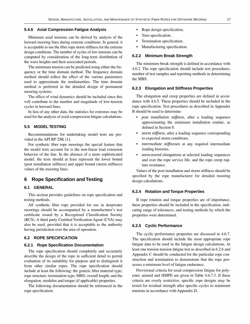
DESIGN, MANUFACTURE, INSTALLATION, AND MAINTENANCE OF SYNTHETIC FIBER ROPES FOR OFFSHORE MOORING 17
5.4.6 Axial Compression Fatigue Analysis
Minimum axial tensions can be derived by analysis of theleeward mooring lines during extreme conditions. In general, itis acceptable to use the Þber rope storm stiffness for the extremedesign conditions. The number of cycles of low tensions can becomputed by consideration of the long-term distribution ofthe wave heights and their associated periods.
The minimum tension can be predicted using either the fre-quency or the time domain method. The frequency domainmethod should reßect the effect of the various parametersused to approximate the nonlinearities. The time domainmethod is preferred in the detailed design of permanentmooring systems.
The effect of wind dynamics should be included since thiswill contribute to the number and magnitude of low-tensioncycles in leeward lines.
In lieu of any other data, the statistics for extremes may beused for the analysis of axial compression fatigue calculations.
5.5 MODEL TESTING
Recommendations for undertaking model tests are pro-vided in the API RP 2SK [1].
For synthetic Þber rope moorings the special feature thatthe model tests account for is the non-linear load extensionbehavior of the line. In the absence of a more sophisticatedmodel, the tests should at least represent the lower bound(post installation stiffness) and upper bound (storm stiffness)values of the mooring lines.
6 Rope Specification and Testing
6.1 GENERAL
This section provides guidelines on rope speciÞcation andtesting methods.
All synthetic Þber rope provided for use in deepwatermoorings should be accompanied by a manufacturerÕs testcertiÞcate issued by a Recognized ClassiÞcation Society(RCS). A third party CertiÞed VeriÞcation Agent (CVA) mayalso be used, provided that it is acceptable to the authorityhaving jurisdiction over the area of operation.
6.2 ROPE SPECIFICATION
6.2.1 Rope Specification DocumentationThe rope speciÞcation should completely and accurately
describe the design of the rope in sufÞcient detail to permitevaluation of its suitability for purpose and to distinguish itfrom other similar ropes. The rope speciÞcation shouldinclude at least the following: the generic Þber material type;rope structure; termination type; MBS; overall length; and theelongation, modulus and torque (if applicable) properties.
The following documentation should be referenced in therope speciÞcation:
¥ Rope design speciÞcation.
¥ Yarn speciÞcation.
¥ Termination speciÞcation.
¥ Manufacturing speciÞcation.
6.2.2 Minimum Break Strength
The minimum break strength is deÞned in accordance with4.6.2. The rope speciÞcation should include test procedures,number of test samples and reporting methods in determiningthe MBS.
6.2.3 Elongation and Stiffness Properties
The elongation and creep properties are deÞned in accor-dance with 4.6.5. These properties should be included in therope speciÞcation. Test procedures as described in AppendixB should be used to determine:
¥ post installation stiffness, after a loading sequenceapproximating the minimum installation routine, asdeÞned in Section 8.
¥ storm stiffness, after a loading sequence correspondingto expected storm conditions.
¥ intermediate stiffnesses at any required intermediateloading histories.
¥ unrecovered elongations at selected loading sequencesand over the rope service life, and the rope creep rup-ture resistance.
Values of the post installation and storm stiffness should bespeciÞed by the rope manufacturer for detailed mooringdesign calculations.
6.2.4 Rotation and Torque Properties
If rope rotation and torque properties are of importance,these properties should be included in the speciÞcation, indi-cating range of tolerances, and testing methods by which theproperties were determined.
6.2.5 Cyclic Performance
The cyclic performance properties are discussed in 4.6.7.The speciÞcation should include the most appropriate ropefatigue data to be used in the fatigue design calculations. Atleast one tension-tension fatigue test as described in 6.2.6 andAppendix C should be conducted for the particular rope con-struction and termination to demonstrate that the rope pos-sesses a minimum level of fatigue endurance.
Provisional criteria for axial compression fatigue for poly-ester, aramid and HMPE are given in Table 4.6.7.3. If thesecriteria are overly restrictive, speciÞc rope designs may betested for residual strength after speciÞc cycles to minimumtensions in accordance with Appendix D.

18 API RECOMMENDED PRACTICE 2SM
6.2.6 Yarn Properties
The speciÞcation should include principal yarn proper-ties such as break strength, elongation, creep, marine Þnish,and yarn-on-yarn abrasion performance as further describedin 4.2 and 7.2.
6.2.7 Specification of Rope Assembly
The rope speciÞcation should cover details which describethe completed rope assembly for each segment of each moor-ing leg, including, but not limited, to the following:
6.2.7.1 Rope Assembly Interface
Full details of the interface should be speciÞed, includingthe following, as appropriate:
¥ Strength, fatigue, torque performance of the interface, ifthese are different from that of the rope.
¥ Any critical dimensions of the interface, including tol-erances if appropriate.
¥ Material for the interface if essential to the performanceof the assembly.
¥ Description of processes, Þnish, coatings, cathodic pro-tection, and other forms of protection for the interfaceif essential to the performance of the assembly.
6.2.7.2 Rope Assembly Length
The speciÞcation should include the overall installedlength between the interfaces, and the corresponding installa-tion tension or the length of rope required before installationas measured at an agreed reference tension.
The reference tension is a small tension used to straightenout the rope in order to deÞne its length. The reference ten-sion used for these deepwater mooring ropes may be higherthan 1% of MBS as set out for ropes used in other services[21]. The same reference tension should be used for all lengthmeasurements on the particular rope during testing, produc-tion and inspection.
The length of rope produced can be determined using dataon the unit rope weight also derived in accordance with ISOEN 919 [22] or Rope Test Standards by Cordage Institute [23].
The purchaser and manufacturer may need to determine amethod for rope length calculation for delivery. It may beimpractical or impossible to measure the entire length of therope assembly, especially at a high tension. This might bedone by determining the length per unit weight of a sample ofthe particular rope type at a speciÞed tension, and then deter-mining the length of the rope by weight. Alternatively thismight be done by calibrating a pulley-like device with revolu-tion counter, and then determining the length of rope bydrawing the rope over that pulley.
The rope assembly length will change subsequent to mea-surement due to relaxation of the rope structure, reelingstrains and changes in load, humidity and temperature during
shipment and handling. The tolerance on the assembly lengthshould be established in collaboration with the rope manufac-turer, taking into account its effect on the mooring systeminstallation.
6.2.7.3 Rope Termination
The types of rope terminations, e.g., splice, potted socket,wedged socket, etc., which are used to secure the rope to theinterface should be speciÞed. The purchaser may alsorequest the rope manufacturer to provide an estimated ratioof the aggregate yarn strength to the minimum terminatedrope breaking strength. The purchaser and manufacturershould agree on the method of determining the aggregateyarn strength.
A discussion of the speciÞcation for different terminationtypes is presented below.
a. Spliced EyesThe speciÞcation should include the splicing procedures.
Unless otherwise speciÞed, the eye size should be determined asthe dimension from the inside back of the eye to the crotch ofthe eye with the two legs of the eye close together as shown inFigure 6.2.7.3. The tolerance should not be less than the stateddimension nor more than 20% greater than the stated dimension.
Hardware may take the form of one piece Þttings or of sep-arate bushes and shrouds. In the latter case the bush acts asthe interface between the rope eye and the connecting shacklepin. The shroud, which Þts over the bush, retains the eye inposition preventing asymmetric loading and protectingagainst abrasion. The bush should be a neat Þt on the shacklepin and the root diameter should be speciÞed. The crush resis-tance of the bush material should be such that it can withstandthe MBS of the rope assembly. This should be demonstratedthrough prototype testing.
Hardware should be free of sharp edges and rough surfaceswhich might cut or abrade the rope or chafe protection. Themouth of a thimble should be ßared and rounded to reducechaÞng. When the thimble is shackled to a chain, the thimbledesign should have provision to prevent the shackle frommoving forward and contacting the rope. All hardware shouldbe designed so that the rope eye remains securely in positionduring deployment, in-service and recovery operations.
Unless otherwise speciÞed, the load at which the thimblestarts to yield should be greater than the MBS of a single legof the rope assembly. The strength of the thimble should bedemonstrated through testing of a prototype of a representa-tive size of the rope to be applied.
b. Sockets and Other TerminationsAs an alternative to spliced eyes the rope assemblies may
be Þtted with socket terminations. These may be appliedusing cast resin cones, by the use of barrel-and-spike or byusing a combination of these techniques. The choice of termi-nation should be suitable for the particular rope construction.

DESIGN, MANUFACTURE, INSTALLATION, AND MAINTENANCE OF SYNTHETIC FIBER ROPES FOR OFFSHORE MOORING 19
The effectiveness of the termination should be demonstratedthrough prototype testing.
The socket should be designed to have yield strengthgreater than the MBS of the Þber rope so that the connectionpin can be removed and replaced without unreasonable appli-cation of force on completion of a break load test.
Socket design and material selection should address factorssuch as fatigue and corrosion to ensure that the termination isadequate for the service life of the mooring system.Resin sys-tems should be chosen with care to ensure chemical compati-bility with the rope materials and suitability for prolonged seawater immersion.
Detailed socketing procedures which match the proceduresused for the prototype testing should be speciÞed, althoughthe prototype work may have been carried out on dummysockets with the same basket proÞle as production Þttings.
6.2.7.4 Rope Jacketing and Protection
The form of jacketing or protection to be placed on the rope,e.g., braided jacket, elastomer cover, etc. should be speciÞed.
The speciÞcation should include the type and quality ofrope jacket, in particular requirements for exclusion of partic-ulate matter, and for free ßooding of the rope structure ifrequired.
Details concerning the jacket design can be found in 4.4.
6.2.7.5 Assembly Marking
Appropriate markings should be placed on each ropeassembly. The speciÞcation should include the location(s)and means of applying these markings.
This may include the following:¥ Axial stripe along the length of the assembly.¥ Markings along the length of the assembly to indicate
length from a termination to facilitate installation andinspection.
¥ Marker tape.¥ A serial number and/or a leg designation to uniquely
identify the speciÞc rope assembly.¥ A manufacturing or inspection date.¥ The name of the manufacturer.¥ The material and other characteristics of the rope.
Figure 6.2.7.3—Diagram of Eye Splice Showing Features and Tolerances

20 API RECOMMENDED PRACTICE 2SM
6.2.7.6 Other Assembly Features
Some other aspects which might be included in the speciÞ-cation include bend restrictors at terminations, abrasion pro-tection at terminations, special abrasion or silt protection indip section, and ßotation on part or all of the rope.
6.2.7.7 Packing, Shipping and HandlingParticular packing, shipping and handling procedures
should be included in the speciÞcation.Details concerning limitations on handling procedures
(e.g., limiting local and global pressures on rope), minimumbend radii (e.g., for spooling, etc.), should be speciÞed.
For extremely long lengths of rope with large diameters itmay be necessary to utilize cable laying techniques and for therope to be laid into special storage tanks on a dedicated vessel.
In most situations the rope assemblies will be supplied onreels. Logistics, installation techniques and economics willdetermine how installation or transportation reels are speci-Þed.
Installation reels can be taken directly from the productionfacility to the installation vessel and used for deployment. Inthis case, dimensions of the reel and its strength and the wind-ing tensions should be carefully designed to ensure a troublefree installation.
Transportation reels are typically used only for storage andtransportation, the rope subsequently being rewound onto amore substantial reel for installation. In this case, consider-ation should be given to the reel dimensions to suit therewinding operation.
In both cases reels may be constructed with two compart-ments. The larger compartment to hold the major componentof the rope length, the smaller one to hold the two ends of therope complete with terminations. The reel should be largeenough to accommodate the complete assembly without anyportion protruding above a ßange.
The reel should be provided with suitable means for lifting,which prevent damage to the reel during crane handling. Fig-ure 6.2.7.7 shows an example of a suitable lifting arrange-ment using lifting lugs and a spreader bar.
Metal-end Þttings should be individually wrapped or oth-erwise kept separate to prevent chaÞng of any underlyingÞber rope. The Þnished package should be securely wrappedwith weather proof material and battens secured betweenthe ßanges.
Each reel should be clearly labelled to identify the contents.
6.3 ROPE TESTING
6.3.1 General
The following rope tests should be conducted to determineor demonstrate rope properties:
¥ Break test.¥ Static extension test.
¥ Dynamic extension test.¥ Tension-tension fatigue qualiÞcation test.The following rope tests may be conducted to demonstrate
rope properties:¥ Torque and rotation test.¥ Axial compression fatigue test.
6.3.2 General Testing Practice
The rope tests can be performed on a prototype rope afterthe rope design is documented to demonstrate the rope prop-erties, on a prototype rope at the beginning of production toan order, or on a sample rope taken during or after productionof an order. Rope testing should be conducted according toAppendices A through D or equivalent rope testing practicesas speciÞed by a RCS.
6.3.2.1 Test Sample Length
The rope test sample for all tests should have adequatelength of undisturbed rope to ensure that the test sample isrepresentative of the actual deployed rope.
6.3.2.2 Wet Testing
¥ All testing should be conducted with the rope in its wet-ted state. This may involve submergence of the rope inwater during testing, or the wetting of the rope duringtesting. Soaking of rope prior to testing may be ade-quate provided that during testing, the rope does notdry out.
6.3.2.3 Reference Load
As discussed in 6.2.7.2, a uniform reference load should beapplied as part of tests involving length measurements.
6.3.2.4 Bedding-in
A few load cycles should be applied before taking lengthmeasurements and also before conducting break tests. Theseserve to bedding-in the rope structure, stabilizing the ropelength and increasing rope and termination efÞciencies.
6.3.2.5 Machine Accuracy
The test machine should be calibrated to provide at least± 2% accuracy of the estimated break strength of the rope.The gauge length should be of adequate length after consider-ation is made of the elongation measurement accuracy. Aminimum of ± 2% accuracy on the elongation measurementshould be used.
6.3.3 Break Strength Test
All tests should be carried out using the same loading pro-cedures in order to maintain consistency. This includes anycycling procedures and load ranges. This is recommended

DESIGN, MANUFACTURE, INSTALLATION, AND MAINTENANCE OF SYNTHETIC FIBER ROPES FOR OFFSHORE MOORING 21
because it has been observed that average break strength gen-erally increases while statistical scatter decreases due to theapplication of a few load cycles. This is due to the setting-inof splices, and the Þbers becoming more orientated into thedirection of load [23].
Test sample preparation and procedures should be in accor-dance with Appendix A.
6.3.4 Static Extension and Creep Test
These tests should be performed in order to determine theminimum post installation stiffness, the likely creep elonga-tion during the lifetime of the unit, and the creep ruptureresistance of the rope. Sample preparation and test proceduresshould be in accordance with Appendix B.1.
6.3.5 Dynamic Extension Test
These tests should be performed to determine the stormstiffness of the Þber rope, and also any other intermediatestiffness which may be required by the mooring designer(e.g., for operational purposes). The mean loads and cycling
amplitudes should be representative of the actual loads antici-pated in situ. The number of cycles and frequency over whichdynamic modulus is measured should also be documented.Sample preparation and test procedures should be in accor-dance with Appendix B.2.
6.3.6 Tension-Tension Fatigue Qualification Test
As indicated in 4.6.7.2, at least one fatigue qualiÞcationtest should be carried out to demonstrate that the Þber ropehas at least equivalent fatigue resistance represented by theselected design curve. SpeciÞcations for the qualiÞcation testare listed in Table 6.3.6.
The test sample should have the same rope construction,Þber material, splice design and thimble as the productionrope and have a minimum diameter scale of 50%. Samplepreparation and test procedures should be in accordance withAppendix C.
Figure 6.2.7.7—Typical Storage Reel and Lifting Arrangement

22 API RECOMMENDED PRACTICE 2SM
6.3.7 Torque and Rotation Tests
The tests described below should be conducted wheretorque and rotation properties are of concern.
a. Rope Torque
The specimen should be terminated in a manner whichresists rotation and which does not affect the measured ropetorque and rotation characteristics. The termination shouldconstrain all components which might signiÞcantly inßuencerotation and torque properties, including the rope jacket.Splices are not acceptable, as they do not provide the sametorque-tension or torsional stiffness characteristics as therope. Resin sockets are preferred.
Other means of rope termination are acceptable provided thatthey meet the above criteria.
The terminations should be of sufÞcient strength to safelywithstand 50% of the minimum break strength.
The tension test machine should be equipped with a torquemeasuring device coupled in series with the rope. This torquemeasuring device should resist any tendency of the rope torotate. The torque measuring device should have an accuracyof ± 1% of the expected maximum rope torque.
The tension test machine should also be equipped with arotation measuring device incorporating a friction compen-sated swivel. This friction compensated swivel should havea means of preventing rotation during the Þrst steps of thetest. This friction compensated swivel should sense andrecord the total rotation with an accuracy of ± 0.3 degreesper meter of rope length (± 0.1 degree per ft) up to theintended maximum tension.
b. Rope/Splice Torque Compatibility
This test should be performed on ropes which will be usedin a mooring leg where torque and rotation properties are ofconcern or interest and where the rope is to be terminated bya splice or by another method which might have torque androtation characteristics different from the rope itself.
One end of the specimen should be terminated in the samemanner as that which would be used on the rope assembly.The other end may be terminated in a manner which resistsrotation but which constrains all components which mightsigniÞcantly inßuence rotation and torque properties, such as
the rope jacket, or alternatively it may be terminated in thesame manner as the Þrst end.
6.3.8 Axial Compression Fatigue Test
Axial compression fatigue testing may be performed todemonstrate that the synthetic rope does not lose signiÞcantstrength when allowed to relax in service, and can be used asevidence that the rope can tolerate axial compression fatiguecriteria less strict than those indicated in 5.3.2. Test samplepreparation and procedures should be in accordance withAppendix D.
6.3.9 Scaling of Rope Data
For the above rope tests except the break strength(6.3.3), the test results can be interpolated or extrapolatedfor ropes made of the same material, construction and ter-mination. A scaling ratio of up to 2:1 in rope diameter canbe used provided that the appropriateness of the chosenscale ratio is demonstrated.
7 Rope Manufacture, Inspection, and Quality Assurance
7.1 GENERAL
A rope product should meet the requirements of the RopeSpeciÞcation as called for in 6.1. A Quality Assurance (QA)program, as described in 7.6, should be developed prior tomanufacturing prototype ropes and accepting orders formooring ropes. This QA program should be followed whenmanufacturing both prototype and production ropes.
7.2 ROPE FIBER MATERIAL
The following procedures should be followed to ensurethat the Þber material used in making the mooring rope isidentical, and within stated tolerances, to the Þber materialused in making the prototype test rope:
7.2.1 Material Certification
The Þber producer should certify the following properties of the yarn:
¥ Fiber type and grade.¥ Finish designation.¥ Merge number and other pertinent identifying
information.¥ Yarn size (linear density).¥ Dry break strength.¥ Dry elongation to break.¥ Wet break strength (nylon only).¥ Wet elongation to break (nylon only).¥ Dry creep.¥ Wet creep (nylon only).¥ Finish level.
Table 6.3.6—Fiber Rope FatigueQualification Test Specification
Design Curve
Minimum Number of
CyclesMean Tension
(% MBS)Tension Range
(% MBS)
Polyester Rope 380,000 30 30Spiral StrandEquivalent
80,000 30 30
Six/Multiple Strand Equivalent
30,000 30 30

DESIGN, MANUFACTURE, INSTALLATION, AND MAINTENANCE OF SYNTHETIC FIBER ROPES FOR OFFSHORE MOORING 23
¥ Finish solubility in water.¥ Wet yarn-on-yarn abrasion.The Þber producer should conduct tests to verify these
properties for the particular grade, type, and designation ofÞber and Þnish at least once each year.
7.2.2 Material Quality Testing
Either the Þber producer or the rope manufacturer shouldconduct the following tests to demonstrate the associated yarnproperties:
¥ Yarn size (linear density).¥ Dry break strength.¥ Dry elongation to break and either.¥ Marine Þnish level.¥ wet yarn-on-yarn abrasion.
7.2.2.1 Responsibility for Material Quality Testing
If the Þber producer is ISO 9000 qualiÞed, then these testsmay be conducted by that Þber producer, either as the yarn isproduced, or as it is prepared for shipment to the rope manu-facturer. Otherwise the rope manufacturer should conductthese tests on representative samples removed at randomfrom yarn shipments as received from the Þber producer.
7.2.2.2 Frequency of Material Quality Testing
At least one yarn sample should be taken at random fromeach 5,000 kg (1,100 lb) of material and tested for yarn size(linear density), dry break strength, and dry elongation tobreak.
At least four yarn samples should be taken at random fromeach 20,000 kg (4,400 lb) of material, and at least once fromthe material for any rope order, and tested for either Þnishlevel or wet yarn-on-yarn abrasion as described below.
Finish level should be determined by Soxhlet extraction(e.g., ASTM D2257) or by an equally accurate analyticaltechnique. Testing should be conducted by the Þber supplier,rope manufacturer, or qualiÞed third-party laboratory with anadequate understanding of analytical chemistry methods anda knowledge of the chemistry of the particular Þber and Þnishto be removed.
Wet yarn-on-yarn abrasion testing should be done in accor-dance with CI 1503 [30] except that only four samples needto be tested and at only one applied tension. The applied ten-sion should be chosen such that the average duration of eachtest is approximately 5,000 cycles.
7.2.3 Material Storage and Handling
All Þber materials to be used in manufacturing the ropeshould be identiÞed and controlled while in storage, transit,and the manufacturing process.
Each Þber material package and each container of Þbermaterial packages should be distinctly labelled with the iden-tity of the Þber material.
Once the Þber material enters the rope manufacturing pro-cess, each material container or major package should belabelled whenever it moves to another manufacturing step oris placed in storage. If the container might be used for othermaterials, the label should be removed from the container assoon as the material is taken from it.
7.3 ROPE MANUFACTURING
The rope manufacturer should prepare a manufacturingspeciÞcation which completely describes the rope construc-tion and parameters and the steps and processes used in mak-ing the rope.
This manufacturing speciÞcation should be at least as com-plete, as described in the OCIMF Hawser Guidelines [8],including quality control checklists.
This manufacturing speciÞcation should be reviewed andapproved by a RCS at the time prototype ropes are manufac-tured or prior to the beginning of manufacturing ropes to aproduction order (whichever comes Þrst).
During manufacturing of both prototype ropes and produc-tion ropes to an order, the manufacturer should completelyfollow the manufacturing speciÞcation for the particular ropedesign. Any deviations from the manufacturing speciÞcationshould be brought to the attention of the purchaser, the inspec-tor, and if applicable, the classiÞcation society and the regula-tory authority.
7.4 TERMINATION
The rope manufacturer should prepare a termination speci-Þcation which completely describes the rope construction andparameters and the steps and processes used in making therope termination.
This termination speciÞcation should be at least as com-plete, as that described in the OCIMF Hawser Guidelines [8],including Quality Control Checklists.
This termination speciÞcation should be reviewed andapproved by an RCS at the time prototype ropes are manufac-tured or prior to the beginning of manufacturing ropes to aproduction order (whichever comes Þrst).
During termination of both prototype ropes and productionropes to an order, the manufacturer should completely followthe termination speciÞcation for the particular type of termi-nation. Any deviations from the termination speciÞcationshould be brought to the attention of the purchaser, the inspec-tor, the classiÞcation society, and the regulatory authority.

24 API RECOMMENDED PRACTICE 2SM
7.5 ASSEMBLY
The rope manufacturer should assemble the rope in accor-dance with the purchaserÕs speciÞcations and instruction, andthe details as called for in 6.1.7.
7.6 INSPECTION
7.6.1 Introduction
A third-party inspector, who represents the RCS and/or thepurchaser and is knowledgeable of rope designs, manufactur-ing processes and termination procedures, should beemployed to conduct the rope inspection.
The rope manufacturer should prepare appropriate inspec-tion checklists and report forms. These should be at least ascomprehensive as those given in the OCIMF Hawser Guide-lines [8].
7.6.2 Review of Rope Documentation
The inspector should have access to all relevant rope docu-mentation, even though these may be proprietary.
7.6.3 Inspection During Production
The inspector should have access to the rope making andassembling facilities at any time while rope production andassembly are in process. This includes operations of assem-bling yarns, assembling strands, making ropes, terminatingropes, and testing materials.
At the option of the certiÞcation authority and with theagreement of the rope manufacturer, the inspection steps andprocedures may be carried out during one visit or may be car-ried out during several visits.
The inspector should complete the inspection checklistfor each rope inspected. This document should be made apart of the quality control report and maintained by the ropemanufacturer.
7.6.4 Selection of Sample Rope Section
The inspector should select the end of rope from which thesample rope section is taken prior to splicing. One such sam-ple rope section should be taken for each continuous length ofrope, or from one of the cut points if that continuous length isto be cut into shorter lengths before splicing.
The length of rope should be pulled from the reel on whichit was made, laid out on a smooth surface, and loaded to a ref-erence tension agreed by the rope manufacturer for two min-utes by means which do not damage the rope. At the end ofthis time, a length of 2 m (6.6 ft) should be marked accuratelyon the surface of the rope. The load should be released, therope cut cleanly and squarely at these marks and the endssuitably secured to prevent unravelling.
7.6.5 Inspection of Sample Rope Section
The two-meter sample rope section should be weighed toan accuracy of ± 1% and the weight divided by 2 to determinethe weight per meter.
The non-load bearing outer jacket of the sample should becarefully removed and the weighing operation repeated todetermine the weight per meter of the load-bearing core.
The total number of strands in the load-bearing core shouldbe counted and recorded. The numbers and dispositions of thestrands should be the same as given in the manufacturingspeciÞcation. Extra colored marker strands are not counted.
The inspector should carefully examine the material andconstruction of the rope, and assure that the numbers andarrangements of yarns and strands comply with the manufac-turing speciÞcation.
The total number of rope yarns in one strand should becounted and recorded. For strands containing less than 50yarns, the number and distributions should be the same asgiven in the manufacturing speciÞcation. For strands contain-ing more than 50 yarns the number should be within ± 4% ofthe value given in the manufacturing speciÞcation. Extrayarns caused by over runs should be permitted.
The rope manufacturer, in the presence of the inspector,should conduct sufÞcient testing to conÞrm the Þber materialused in producing the rope. The Fiber Material IdentiÞcationTests given in the OCIMF Hawser Guidelines [8] or othersuitable test methods should be used.
The inspector should examine all identiÞcation marks toensure they comply with 6.2.7.5.
7.6.6 Determination of Rope Strength
During prototype rope manufacturing and testing, the ropestrength factor (the ratio of rope break strength to aggregateyarn strength) should be determined using the proceduresgiven in the OCIMF Hawser Guidelines [8]. These tests andcalculations should be witnessed and certiÞed by an indepen-dent inspector.
During rope manufacturing, the inspector should removesufÞcient samples of Þber material from the sample rope sec-tion or the Þnished rope product for wet strength testing usingthe same procedures as were used with the prototype rope.These samples should be tested in the presence of the inspec-tor. The inspector should verify that the calculated productionrope strength, using the same procedures as were used withthe prototype rope and the rope strength factor which wasdetermined for the prototype rope.
7.6.7 Inspection of Rope Termination
The selection of terminations for inspection should be atthe discretion of the inspector. At least one terminationassembly or application should be witnessed by the inspectorfor each rope design and termination type.

DESIGN, MANUFACTURE, INSTALLATION, AND MAINTENANCE OF SYNTHETIC FIBER ROPES FOR OFFSHORE MOORING 25
The inspector should examine the selected termination indetail, making reference to the termination procedure given inthe termination speciÞcation and to the completed qualitycontrol checklists, to assure that this has been done.
7.6.8 Inspection of Finished Rope Assembly
The inspector should thoroughly inspect the assembledrope, after application of terminations and as appropriatebefore or after the application of any other appliances andaccessories.
If a method of determining the Þnished rope length is spec-iÞed and agreed to in the purchase order, the rope manufac-turer should carry out that test in the presence of the inspectorto demonstrate the speciÞed length.
7.7 QUALITY CONTROL AND ASSURANCE
7.7.1 Introduction
Appropriate quality assurance procedures are necessary todemonstrate that Þber rope assemblies manufactured againstany speciÞc order have the same qualities as the prototypesand so can be expected to have the same properties withoutrequiring further prototype testing.
7.7.2 Quality Assurance Manual
The rope manufacturer should prepare a quality assurancemanual which completely and accurately describe the qualitycontrol and assurance program used in manufacturing therope.
7.7.3 Quality Assurance Supervisor
The rope manufacturer should designate a quality assur-ance supervisor. The quality assurance supervisor and anydeputies should not be under the authority or control of themanufacturing or sales branches of the rope manufacturerÕscompany organization. The quality assurance supervisor andany deputies should have the authority to stop rope produc-tion when quality assurance is less stringent than the docu-mented procedures or when quality deviates from thespeciÞed values or tolerances.
7.7.4 Quality Control Checklists
The rope manufacturer should prepare quality controlchecklists for the processes of yarn assembly, strand assembly,rope making, rope jacketing, splicing, potted socket applica-tion, wedge socket application, bend restrictor application, andother processes as applicable. Copies of the checklists shouldbe posted at each location where the application is to be car-ried out. The checklists should be followed and completed bythe assembler during the assembly of each termination.
7.7.5 Quality Control Report
The rope manufacturer should prepare a quality controlreport which includes the various quality control checklistsfor the production and assembly of that rope. This reportshould also include the material certiÞcates, material and yarntest results, and rope inspection and test reports as applicable.
The quality control report should be maintained for a mini-mum period of Þve years or longer as appropriate.
8 Rope Handling and Installation
8.1 GENERAL
This section provides guidance for the development of pro-cedures for handling, installation and recovery (if applicable)of synthetic Þber ropes. General requirements will be givenregarding the contents of procedures, and general consider-ations are given concerning handling of Þber ropes, emplace-ment of anchors, installation of mooring lines, hook-up ofmooring lines to the ßoating platform, and tensioning andtesting of the lines of the mooring system.
8.2 GENERAL STORAGE, HANDLING AND INSTALLATION CONSIDERATIONS
Care should be taken in packing synthetic Þber ropes forstorage after manufacture, transportation to site, and duringinstallation. The requirements should be in accordance withthe manufacturerÕs recommendations, and the rope designand properties as found in Section 4.
8.2.1 Ultra-Violet Light and Chemicals
Fiber ropes should be protected from the effects of UVradiation and chemical damage during storage, transportationand installation.
In the absence of detailed information from the rope manu-facturer, Table 6 can be followed with regard to the typicalresistance levels of rope materials to chemical and UV dam-age [24]:
Table 8.2.1—Resistance to Chemical and UV Weakening
Polyester Aramid HMPE NylonSteel (for
comparison)
Chemicals good 1 good 1 excellent good 1 varies 2
UV light3 good fair fair good excellent
Notes: 1 Attacked by strong alkalis and acids.2 Corroded by water, acids etc.3 Protective coatings and jackets can greatly reduce the harmful effectsof sunlight on ropes manufactured with high tenacity Þbers [24].

26 API RECOMMENDED PRACTICE 2SM
8.2.2 End Fittings
Connecting hardware which has sharp and/or protrudingedges should be avoided when ropes are stored and/orwrapped onto a spool. If this is not possible, adequate protec-tion should be provided to prevent chaÞng of the ropes in thestorage spools.
As indicated in 4.5.2 of this document, the usage of steel orother terminations may complicate the handling of the termi-nated ends of the line as care must be taken to ensure thatexcessive bending is not applied to the Þber rope which mightcause compression damage to Þbers. Bend restrictors Þtted tothe end of the Þber rope may be advantageous in avoiding orreducing this problem.
Lighter weight terminations and Þttings using materialsother than steel, such as composites, may be used if their per-formance has been proven to be satisfactory
In the case of very long lines it may be necessary to pro-vide mid-length connections by means of hard connectorssuch as spliced eyes with thimbles and connection shackles.Special consideration needs to be given to handling of theconnection parts of the rope.
8.2.3 Twisting from Unbalanced Torque
As noted in 4.4.1, markings along the rope may be used toassist in monitoring the torsion/twist free rope during deploy-ment. Twisting or unwinding of Þber rope may be a problemfor pre-deployed mooring line when connected to a surfacebuoy. The maximum twist during installation should notexceed the manufacturerÕs limits based on torque tests asdescribed in 6.3.7.
As discussed in 4.6.9, twist might be induced into compo-nents and then transferred between them during installationprocedures. This may cause serious operation problems andshould be avoided. Work wires of a non-torque balanced type(e.g., six strand wires) should not be used, unless consider-ation has been made for the effect of any twist induced intothe installed mooring components.
8.2.4 Bending Radius
As indicated in 4.4.3, the installation minimum bendingradii (MBR) quoted for installation or maximum design con-ditions (which may be Ôone-offÕ events) may not need to bethe same as for storage conditions, since storage is associatedwith prolonged static bending. The rope manufacturer shouldestablish the limits of drum diameter to rope diameter ratiosfor installation and handling, taking into account the associ-ated working tensions of the mooring lines.
Deepwater mooring Þber ropes should not be permanentlyinstalled around bollards or fairleads. This is because of thelimited knowledge of their long term behavior under fatiguetension and bending and the potential for signiÞcant wear and
internal Þber damage to occur in the length of rope in contactwith the bollard or fairlead.
During deployment rope assemblies will need to be storedand reeled around drums, fairleads and rollers. Failure of theexternal rope sheath (particularly the extruded polymer type)may result in a local bending stiffness discontinuity. Thiscould become an area for bending fatigue damage to concen-trate. Adequate steps should be taken in the design and instal-lation to avoid this type of damage.
8.2.5 Cutting and Abrasion
All handling equipment [25] should not induce any detri-mental loading into Þber ropes, such as excessive bending,chafÞng, grinding, cutting, etc. Any restrictions concerningthe use of clamping devices or other stopping devices in thedeployment of Þber ropes should be established.
Care should be taken when applying shearing forces to Þberropes. Shear can be induced by friction as the rope runs over abollard, or when gripping the rope to apply tension. Shearingloads may result in damage to the rope jacket or core.
8.2.6 Heat Damage
As indicated in 4.6.6, the Þber maximum working temper-ature should not be exceeded. In this respect ropes should notbe located near to heat sources such as welding, steam pipes,engine exhausts, heaters, etc. Heat build-up from frictionaleffects during deployment and re-spooling should be moni-tored and cooling methods such as water spray or other alter-native means should be considered. Heat build-up may alsobe more severe if Þber ropes are running over surfaces whichnaturally provide insulation such as painted surfaces.
8.2.7 Foreign Particles
As noted in 4.4.5, the presence of foreign particles such asblasting grit, sand, etc. should be prevented from coming intocontact with the ropes. When the installation work is laid updue to weather or other reasons, protective covers should beprovided to protect the rope from foreign matters and exces-sive UV exposure.
8.2.8 Wire Rope/Synthetic Rope Mix
During spooling and re-spooling, wire rope and syntheticrope should not be mixed on the same drum unless some formof segregation such as dividers can be provided.
8.2.9 Fiber Rope Weight
Fiber ropes have signiÞcantly lighter weights (both inwater and in air) than steel wire rope or chain lines of equiva-lent strength and this feature makes them particularly attrac-tive for installation of moorings in very deep water.

DESIGN, MANUFACTURE, INSTALLATION, AND MAINTENANCE OF SYNTHETIC FIBER ROPES FOR OFFSHORE MOORING 27
Rope diameters of Þber ropes (particularly for polyester)are likely to be bigger than steel wire rope and this inßuencesthe space required to store the lines prior to deployment.
Ropes that are positively buoyant may present some han-dling challenges during deployment; however the exact levelof buoyancy for a rope depends not only on the Þber densitybut also on the ßooding characteristics of the rope and thedensity of the jacket.
8.2.10 Salt Crystallisation
Fibers which are alternately wetted with salt water andallowed to dry out can suffer from abrasion damage from theinternal formation of salt crystals. For the deepwater mooringlines this will not occur during deployment in a permanentmooring system as the ropes will be completely submerged.
8.3 INSTALLATION DESIGN CONSIDERATIONS
8.3.1 Deployment
Rope spooling tension should be kept consistent with thedeployment tension to prevent any detrimental effects on the Þberropes. Handling equipment usually associated with conventionalsteel wire or chain moorings should not be used unless it canbe shown that the equipment does not adversely affect therope and jacket design. Deployment techniques of polyesterrope from installation vessels may include the use of rotarywinches, traction winches, capstan or warping head typewinches, or caterpillar type winches or hand-over-hand meth-ods using special grips. Interference type stoppers designedfor use with steel wire rope or chain should not be used forhandling Þber rope. If necessary several links of chain can bepermanently added to the rope termination and the clamp canbe used on the chain links.
Only a small proportion of the strength capacity of a ropecan be transferred in shear by means of gripping the rope withlinear winch grips or rope stoppers. Means for gripping ofsynthetic rope should be suitable for the stopper loadsrequired and should be approved by the rope manufacturer.Grips, stoppers or Chinese Þngers type stoppers should onlybe used within the load limits established by the rope manu-facturer. Grips or clamps should be free of sharp edges, andexert their gripping force over a sufÞcient length of rope inaccordance with the rope manufacturerÕs recommendations.
During deployment the Þber rope should be separated fromthe termination hardware by means of split reels or specialwrapping of the hardware.
Damage can occur if Þber ropes are unreeled from looselytensioned drums with the result that the line becomes buriedin the lower wraps of rope. This must be avoided by design-ing the rope reeling tension to be consistent with the tensionapplied during deployment.
Care should be taken to minimize the time that the rope isstationary on a stern roller, deployment sheave or overboard-
ing fairlead, while the rope is under signiÞcant load, in orderto prevent rope damage. In case unexpected events cause ropedeployment stoppage while contacting the stern roller, proce-dures should be developed to mitigate the localized abrasion,bending fatigue, and heat build-up damages.
8.3.2 Minimum Tension and Maximum Allowable Low Tension Cycles
During the installation a minimum line tension in the syn-thetic Þber rope should be maintained to prevent lines frompossible compressive damage. If the installation methodresults in excessive number of load cycles of loading in whichthe line tension goes from the installation tension to below theguideline limit provided in 3, then analysis will be required todemonstrate acceptability. An analysis should demonstratethat the total number of load cycles going below the guidelinetension for both the installation phase and the remaining life-time of the installation does not exceed the limiting valuelisted in Table 4.6.7.3 of this document.
Activities which might result in such loading includedeployment of anchors and anchor proof loading.
For the pre-deployed lines awaiting the arrival of the plat-form, the environmental loads may induce small tension vari-ations in the synthetic Þber rope. To prevent the rope frompossible compressive damage, the pre-deployed line shouldbe maintained at a minimum mean tension of 5 tonnes forpolyester ropes and 2% of MBS for higher modulus ropes(Aramid and HMPE). As such, counting of load cycles is notrequired for pre-deployed lines.
8.3.3 Contact with Seabed During Deployment
During deployment, Þber rope contact with the seabed isundesirable. Where Þber ropes have been accidentallydropped to the seabed, the ingress of foreign particles such assand will affect the ropeÕs yarn-on-yarn abrasion resistanceand hence will adversely affect the ropeÕs fatigue life. Unlessit has been demonstrated through testing that the rope jacketis impermeable to damaging ingress of the silt and other par-ticles present on and near the seabed, a rope which is droppedto the seabed should not be used until it is demonstrated thatthe rope has retained 90% of the required design strength ofthe mooring line as detailed in 9.4.1.
In most instances, it is necessary for the Þber rope to bepre-deployed prior to hook-up with the installation. Anyinstallation proposal involving the pre-deployment of Þberlines on the seabed should for example include: suitable justi-Þcation through testing or otherwise that the jacket can pro-vide adequate resistance to the ingress of sand; foreignparticle ingress protection at rope terminations; bottom stabil-ity (if laid on bottom); environmental loading such as wavesand current; rope compression fatigue; rope buoyancy consid-erations (i.e., ßooding or non-ßooding rope); buoy (if used)structural integrity and size. Other considerations such as the

28 API RECOMMENDED PRACTICE 2SM
site-speciÞc nature of marine operations and particular Þberproperties should also be included.
8.3.4 Connection to Anchors
Connection of the mooring line to the anchor may be madeeither on the surface or after the anchor has been installed.The ability to make a subsea connection of the line to theanchor will depend on the type of connection hardware speci-Þed and the power and capability of the available RemoteOperation Vehicle (ROV).
In case the mooring line and its Þber rope segments are pre-connected to the anchor prior to anchor deployment, careshould be taken to avoid damage to the Þber rope as a result ofcontact with adjacent equipment, other installation lines, or theseabed. Potential damages that should be avoided are:
¥ Abrasion or fouling of the mooring line with the anchorsystem, anchor chain, separate anchor lowering linesand bridles, connectors, etc.
¥ Uncontrolled twisting of the Þber rope and/or adjacentwire ropes due to lack of torque matching betweenmooring line Þber rope and steel rope segments, and dueto lack of torque balance in anchor lowering lines.
¥ Increased risk of the contact between Þber ropes andseabed, if the mooring line is used for the embedmentof anchors, and this embedment requires a low mooringline angle at the seabed.
For anchors which will be connected to the synthetic Þbermooring lines, a length of chain or wire rope should be usedto keep the Þber rope clear of the seabed to avoid damage dueto particle ingress, and damage to Þber rope during anchorhandling on board the installation vessel. The length of thissteel line segment may also depend on the selected presetconÞguration of the mooring legs.
8.3.5 Temporary Moored Units
Design should account for the necessary steel wire/chainsegments (i.e., for connection to winches, to avoid bendingover sheave fatigue, creep elongation, other marine winchingoperations, etc.) and at the anchors (see 8.3.4 above). Break-ing-out of anchors such as drag embedment anchors shouldbe monitored carefully (if Þber ropes remain attached), sincethere may be some possibility of undesirable Þber rope load-ing such as compression damage. Where the temporarymoorings will require regular handling of Þber ropes due torepeated deployment and recovery, the use of Þber ropeswhich have high resistance to external abrasion should beconsidered.
Mooring test load requirements for temporary moorings canbe found in API RP 2SK [1], 6.6.5. The mooring test load forÞber ropes in temporary mooring systems should also satisfythe need to achieve an acceptable post installation stiffness ofthe Þber ropes. The level of post installation stiffness required
for the Þber rope should be veriÞed by the mooring systemdesigner based on the maximum allowable vessel excursionsduring operating and survival conditions, and be consistentwith the rope testing. During operations, the mooring leg ten-sions should be monitored regularly, and the mooring line ten-sions should be adjusted as required to maintain a minimumoperating tension speciÞed by the mooring designer.
8.3.6 Permanent Moored Units
Similar to temporary moorings, a suitable length of steelwire or chain should be provided at the top and bottom endsof the synthetic rope mooring leg for permanently mooredunits. The upper steel line segment can be used for adjust-ments of the mooring leg tension needed to allow for ropeextension and creep. Therefore, suitable equipment foradjusting the length of the upper steel line segment should beprovided for each mooring leg. Further, the length of theupper steel line segment should be adequate to ensure that theupper end of the Þber rope remains, during the platformÕs ser-vice life, at a depth where it is clear of mechanical damagefrom surface vessels and surface marine activities, harmfulsunlight penetration, and salt encrustation.
Mooring test load requirements for permanent moorings canbe found in API RP 2SK [1], 6.6.5. The mooring test load forÞber ropes in permanent mooring systems should also satisfythe need to achieve an acceptable post installation stiffness ofthe Þber ropes. The level of post installation stiffness requiredfor the Þber rope should be veriÞed by the mooring systemdesigner based on the maximum allowable platform/vesselexcursions during operating and survival conditions, and beconsistent with the rope testing. While in service, the mooringleg tensions should be monitored regularly, and the mooringline tensions should be adjusted as required to maintain a min-imum operating tension speciÞed by the mooring designer.
8.3.7 Snap-back Behavior
If lines fail under tension during the installation stage thereis signiÞcant potential for injury to personnel and damage toequipment as a result of rope snap-back energy. The installa-tion phases should be planned to minimize the risk of such anincident. As a general health and safety requirement, person-nel should be kept clear of ropes under tension whether theybe steel wire or Þber ropes.
Methods of designing against or minimizing snap-backdamage include the minimizing of line tension during opera-tions when personnel are working close to the rope, and mini-mizing opportunities for the taut line to be abraided ortouched by other items of equipment during installation par-ticularly when under tension.
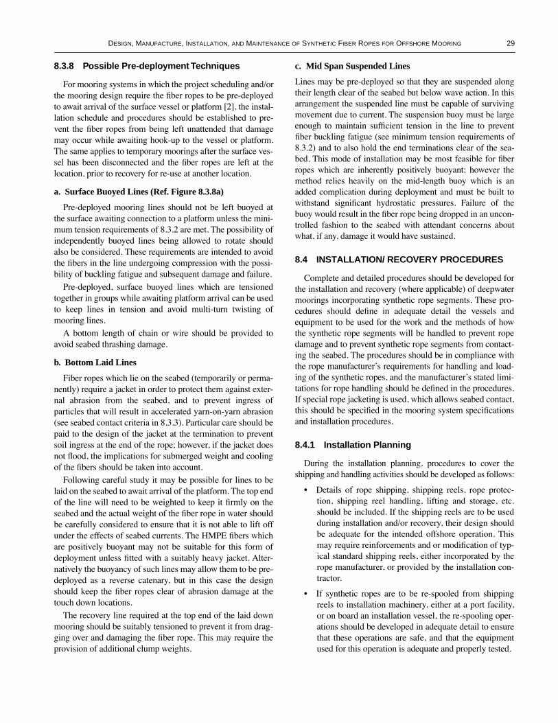
DESIGN, MANUFACTURE, INSTALLATION, AND MAINTENANCE OF SYNTHETIC FIBER ROPES FOR OFFSHORE MOORING 29
8.3.8 Possible Pre-deployment Techniques
For mooring systems in which the project scheduling and/orthe mooring design require the Þber ropes to be pre-deployedto await arrival of the surface vessel or platform [2], the instal-lation schedule and procedures should be established to pre-vent the Þber ropes from being left unattended that damagemay occur while awaiting hook-up to the vessel or platform.The same applies to temporary moorings after the surface ves-sel has been disconnected and the Þber ropes are left at thelocation, prior to recovery for re-use at another location.
a. Surface Buoyed Lines (Ref. Figure 8.3.8a)
Pre-deployed mooring lines should not be left buoyed atthe surface awaiting connection to a platform unless the mini-mum tension requirements of 8.3.2 are met. The possibility ofindependently buoyed lines being allowed to rotate shouldalso be considered. These requirements are intended to avoidthe Þbers in the line undergoing compression with the possi-bility of buckling fatigue and subsequent damage and failure.
Pre-deployed, surface buoyed lines which are tensionedtogether in groups while awaiting platform arrival can be usedto keep lines in tension and avoid multi-turn twisting ofmooring lines.
A bottom length of chain or wire should be provided toavoid seabed thrashing damage.
b. Bottom Laid Lines
Fiber ropes which lie on the seabed (temporarily or perma-nently) require a jacket in order to protect them against exter-nal abrasion from the seabed, and to prevent ingress ofparticles that will result in accelerated yarn-on-yarn abrasion(see seabed contact criteria in 8.3.3). Particular care should bepaid to the design of the jacket at the termination to preventsoil ingress at the end of the rope; however, if the jacket doesnot ßood, the implications for submerged weight and coolingof the Þbers should be taken into account.
Following careful study it may be possible for lines to belaid on the seabed to await arrival of the platform. The top endof the line will need to be weighted to keep it Þrmly on theseabed and the actual weight of the Þber rope in water shouldbe carefully considered to ensure that it is not able to lift offunder the effects of seabed currents. The HMPE Þbers whichare positively buoyant may not be suitable for this form ofdeployment unless Þtted with a suitably heavy jacket. Alter-natively the buoyancy of such lines may allow them to be pre-deployed as a reverse catenary, but in this case the designshould keep the Þber ropes clear of abrasion damage at thetouch down locations.
The recovery line required at the top end of the laid downmooring should be suitably tensioned to prevent it from drag-ging over and damaging the Þber rope. This may require theprovision of additional clump weights.
c. Mid Span Suspended Lines
Lines may be pre-deployed so that they are suspended alongtheir length clear of the seabed but below wave action. In thisarrangement the suspended line must be capable of survivingmovement due to current. The suspension buoy must be largeenough to maintain sufÞcient tension in the line to preventÞber buckling fatigue (see minimum tension requirements of8.3.2) and to also hold the end terminations clear of the sea-bed. This mode of installation may be most feasible for Þberropes which are inherently positively buoyant; however themethod relies heavily on the mid-length buoy which is anadded complication during deployment and must be built towithstand signiÞcant hydrostatic pressures. Failure of thebuoy would result in the Þber rope being dropped in an uncon-trolled fashion to the seabed with attendant concerns aboutwhat, if any, damage it would have sustained.
8.4 INSTALLATION/ RECOVERY PROCEDURES
Complete and detailed procedures should be developed forthe installation and recovery (where applicable) of deepwatermoorings incorporating synthetic rope segments. These pro-cedures should deÞne in adequate detail the vessels andequipment to be used for the work and the methods of howthe synthetic rope segments will be handled to prevent ropedamage and to prevent synthetic rope segments from contact-ing the seabed. The procedures should be in compliance withthe rope manufacturerÕs requirements for handling and load-ing of the synthetic ropes, and the manufacturerÕs stated limi-tations for rope handling should be deÞned in the procedures.If special rope jacketing is used, which allows seabed contact,this should be speciÞed in the mooring system speciÞcationsand installation procedures.
8.4.1 Installation Planning
During the installation planning, procedures to cover theshipping and handling activities should be developed as follows:
¥ Details of rope shipping, shipping reels, rope protec-tion, shipping reel handling, lifting and storage, etc.should be included. If the shipping reels are to be usedduring installation and/or recovery, their design shouldbe adequate for the intended offshore operation. Thismay require reinforcements and or modiÞcation of typ-ical standard shipping reels, either incorporated by therope manufacturer, or provided by the installation con-tractor.
¥ If synthetic ropes are to be re-spooled from shippingreels to installation machinery, either at a port facility,or on board an installation vessel, the re-spooling oper-ations should be developed in adequate detail to ensurethat these operations are safe, and that the equipmentused for this operation is adequate and properly tested.

30 API RECOMMENDED PRACTICE 2SM
8.4.2 Installation Operations
Installation operations will depend upon the mooring sys-tem being installed, the equipment available for the installa-tion, prevailing weather conditions and sound site decisions.Detailed offshore installation (and recovery if applicable)procedures should therefore include the following criticalelements:
¥ Arrangement of installation machinery/equipment onboard the installation vessel.
¥ Stability assessment of the installation vessel and rec-ommended loading conditions to maintain vessel sta-bility and minimize motions (if applicable).
¥ Seafastenings/tie-downs of installation machinery andequipment. If this equipment is not part of the normalvesselÕs equipment, and is installed speciÞcally for theoperations, special attention should be paid to thedesign and fabrication of equipment tie-downs, andequipment power supply and control systems. Equip-ment tie-downs should be adequate for survival ofstorm conditions offshore in standby mode. If the sur-vival motions of any installation equipment on board
the installation vessel is limited, these limits should bespeciÞed, and procedures developed for timely returnto port of the installation vessel.
¥ Procedures for the deployment of anchors, whichshould prevent damage to any mooring leg compo-nents, and which should eliminate risk of entanglementbetween synthetic rope segments and steel mooringline components or any separate anchor deploymentlines. If the anchor is lowered on a separate deploymentline, there should be adequate separation between thisdeployment line and the mooring leg being deployed,to prevent such entanglement, and prevent spinning ofthe anchor during deployment/recovery.
¥ Procedures for the deployment of the mooring leg com-ponents, whether steel or synthetic, including details ofthe equipment to be used for the deployment/recoveryof all components, and including details of installationvessel position, heading, movement, etc.
¥ The procedures should demonstrate that the syntheticrope sections can be safely deployed/recovered by theproposed equipment, without damage to the rope, its
Figure 8.3.8a—Surface Buoys Tensioned Together to Maintain Fiber Rope in Tension

DESIGN, MANUFACTURE, INSTALLATION, AND MAINTENANCE OF SYNTHETIC FIBER ROPES FOR OFFSHORE MOORING 31
jacket (if used) and its terminations. Testing of the syn-thetic rope handling/installation equipment may berequired to demonstrate the safety of the operations.
¥ Typically, mooring lines with synthetic rope segmentsdo not lend themselves well for deployment from theMODU or FPS vessel. Therefore these systems areexpected to be pre-deployed, and left at the site, untilthe MODU or FPS can be connected to the presetmooring system. The pre-installed conÞguration of themooring system should be carefully considered, andfully detailed, in order to minimize damage to the sys-tem while left unattended. To minimize low tensionload cycles, special arrangements may be required,which either ensure the minimum tension applicablefor the type of synthetic rope, or which limit or mini-mize load cycling at low tensions.
¥ If large surface buoys are used to support the presetmooring legs, they should be suitably marked to mini-mize the risk that such buoys can be overrun by ship-ping, which may result in synthetic line segmentsdropping on the seabed. If this is considered a seriousrisk, the manner in which the mooring legs are left atlocation may have to be modiÞed, or a vessel may haveto be stationed in the Þeld to warn oncoming trafÞc.
¥ Detailed procedures for test tensioning of the mooringlines and anchors should be developed. Such test load-ing could be performed during pre-installation of themoorings, or after hook-up to the MODU or FPS.
¥ Detailed procedures for the connection and disconnect(if applicable) of the vessel to the preset syntheticmooring system should be developed. These proceduresshould detail the type of installation vessel and specialequipment required, and they should deÞne the towingprocedures, towing vessels and connection sequence.
¥ If there is a signiÞcant risk that synthetic rope segmentsand other mooring line segments can be damaged dur-ing installation and/or hook-up, a suitable number ofspare components should be prepared to replace dam-aged or dropped mooring line components.
¥ Suitable means for stopping off synthetic ropes shouldbe deÞned, and tested if required. Typical means ofstopping off steel lines, such as shark jaws, pelicanhooks, carpenter stops, linear winch grippers, etc. aregenerally not suitable for synthetic ropes, and specialequipment may be required.
8.4.3 Contingency and Inspection Plans
Contingency procedures should be developed, detailingwhat can happen, and what can be done to correct the prob-lem, in case of failure of any of the installation equipment.For example, if the anchor is lowered on a separate line, andthis line or the winch deploying it fails, the mooring leg
deployment equipment should be capable of handling theincreased mooring line load, without signiÞcant damage tothe mooring line, and without pulling the mooring linedeployment equipment off the vessel. The proceduresshould therefore list all plausible failure scenarios, theirimpact, and how the impact of such failures can be miti-gated or minimized.
Load testing of special installation equipment may berequired to demonstrate that the equipment can handle itsmaximum loading in normal and contingency conditions.Detailed inspection of the equipment after load testing shouldbe carried out to ensure that the load test has not initiated anycracking or failure of the equipment and its tie-downs.
If the installation/recovery equipment is used on a regularbasis, regular inspections of the equipment should be carriedout to ensure its integrity. Function testing of hydraulic sys-tems, winch brakes, instrumentation, etc. may be required toensure the equipment is functioning properly, and loads canbe monitored and controlled.
In the case of temporary moorings, where the syntheticmooring ropes are recovered and intended to be moved toanother location, the synthetic mooring rope segments shouldbe carefully inspected in order to determine whether they aresuitable for re-use. Such inspections can be performed off-shore during recovery, or in port. Procedures for the inspec-tion of such ropes, guidelines for rope acceptance/rejection,requirements for testing, and procedures for offshore repairand/or onshore repair should be established and followed inaccordance with 9.4 and in collaboration with the rope manu-facturer before synthetic ropes are recovered and re-used.
9 In-service Inspection and Maintenance
9.1 GENERAL
This section provides guidance for typical in-serviceinspection and maintenance. In general, there are very fewindustry standards concerning this aspect, unlike for steelcomponents (e.g., API RP 2I [26]).
A plan for the Þber rope inspection and condition assess-ment should be developed by the operator of the mooring sys-tem and the manufacturer of the rope in conjunction with thecertifying authority on a case by case basis to provide consis-tency with the overall safety assessment for a given installation.
An individual log should be kept for each rope whichclearly records the history of the rope usage including infor-mation such as rope tensions, relevant environmental condi-tions, and inspection/re-tensioning details on the rope.
9.2 INSPECTION AND TESTING TECHNIQUES
The following provides an overview of the currently avail-able inspection techniques for Þber ropes:

32 API RECOMMENDED PRACTICE 2SM
9.2.1 Visual Inspection Techniques
Present visual inspection techniques are generally limitedto external visual examination only. Inspection of mooringlegs on mobile units can be performed on deck or at docksideduring rig moves. Inspection of installed mooring legs can beperformed using divers or a Remotely Operated Vehicle(ROV).
The success of such inspection techniques clearly dependsupon underwater visibility and extent of marine growth.
9.2.2 Internal Non-destructive Inspection Techniques
Presently, no reliable Non-Destructive Testing methods areavailable for Þber ropes [27]. When NDT techniques becomeavailable, full justiÞcation by trials, etc. should be performedto assess their accuracy and suitability for their intendedusage.
9.2.3 Destructive Inspection and Testing Techniques
It may be prudent to include short Þber rope inserts whichare periodically removed, examined and tested in order todetect internal deterioration, determine residual strength, andestablish appropriate replacement and retirement criteria;however, the increase in the number of terminations and thepotential risk involved in the insert replacement operationshould be considered. Likewise, when a rope is replaced orretired, it may be prudent to examine and test it.
9.3 FIBER ROPE INSPECTION PROCEDURE
Inspection procedure for Þber rope mooring should includea combination of external visual inspection, internal examina-tion and residual strength testing techniques as indicatedabove. The inspection procedure should be developed anddocumented by or in close collaboration with the rope manu-facturer, and should address the following subjects:
¥ Visual inspection requirements for rope core, ropejacket and terminations.
¥ Training of rope inspectors by rope manufacturer.¥ Description of rope strand damage, which will reduce
the rope strength to less than the rated MBS of the rope.¥ Type of acceptable jacket damage, and description of
jacket damage which will require repair.¥ Description of termination damage requiring repairs
and/or re-splicing of the termination.¥ Description of termination hardware damage requiring
hardware replacement.¥ Description of the type of rope and/or termination dam-
age, which would require the rope to be replacedimmediately.
9.3.1 Visual Examination
External visual examinations should be carried out on aregular basis for all Þber rope moorings. Examinations shouldbe performed by a competent experienced inspector, who hasa thorough knowledge of the construction of the rope, thepossible deterioration modes, and the inspection techniques.If possible, involve a representative from the rope manufac-turer. Prior to inspection, it may be necessary to remove anymarine growth or otherwise using suitable means which willnot damage the rope itself. This type of inspection should beable to detect any jacket defects, twist of rope (axial markingreferred in 4.6.9) and any external damage due to Þsh bite. Itmay also be able to detect changes in rope diameter and anybacterial effects at the near sea surface segments. All termina-tions and Þber rope near to the water surface should be exam-ined closely to ensure that no damage has occurred.
9.3.2 Internal Inspection
If external visual examination indicates any uncertainty asto rope integrity, then it may be prudent to remove the rope orsection of rope or rope insert (if present) from service. Adetailed internal examination of the interior of the removedrope should then be conducted in order to identify developingdegradation. The internal inspection may involve removal ofsample yarns and/or rope sub-core strands, for splicing andtesting for general properties such as elongation and breakstrength. Yarn extracts may also undergo microscopic exami-nation by specialist laboratories to determine details such asthe level of foreign particle ingress.
9.3.3 Fiber Rope Inserts
The use of Þber rope inserts may be more applicable to per-manent units. If inserts are to be used, then it is recommendedthey be used at the near-surface termination for ease ofreplacement/access, and also because this is the likely regionof damage due to Þsh bite, UV, chemical action, bacterialaction, etc. Practically, the uppermost segment is also usuallysubject to the maximum current velocity, wave motion andmaximum line tension. These inserts can be removed andtested at testing laboratories in order to assess damage, byfatigue testing followed by break tests. Test sample prepara-tion and procedures should be in accordance with 6.3. Recov-ery and replacement of complete lines can be based onresidual strength tests of inserts. The lengths of availablebreak test machines may govern the Þber rope insert length.
9.3.4 Inspection of Fiber Ropes for Temporary Moorings
For mobile units (e.g., MODUs) regular inspection of Þbermooring ropes may be feasible, while the Þber rope mooringsare recovered before they are re-deployed at a new location.In general, before a Þber rope is re-installed it should be care-

DESIGN, MANUFACTURE, INSTALLATION, AND MAINTENANCE OF SYNTHETIC FIBER ROPES FOR OFFSHORE MOORING 33
fully inspected for abrasion of the jacket and rope core, dam-age to terminations, and termination hardware. Suchinspection can be performed during recovery of the mooringson board the recovery vessel, or it can be performed at a baseport facility.
It is likely that ropes used in temporary moorings will getdamaged more often than their permanent counterparts, andmay be subject to additional fatigue damage associated withmultiple deployment and recoveries. This additional fatiguemay not be detectable through external visual inspections sodestructive testing techniques will have to be used. The fre-quency of conducting the destructive testing should be estab-lished based on an accurate log of the rope usage, and inassociation with the rope manufacturer and the certifyingauthority. The Þrst destructive test the Þrst time a particularrope is used should be carried out as soon as possible afterone year of accumulated service.
9.4 ROPE RETIREMENT CRITERIA
The rope retirement criteria should be based on appropriatetesting of rope or rope inserts for residual strength and suit-able inspection techniques and procedures as described above.
9.4.1 Damage Assessment
Rope that has been damaged accidentally during installa-tion may be put in service provided certain criteria are met.Procedures for determining whether a damaged rope can beretained in service should be established and approved by thecertifying authority. These procedures will depend upon therope construction and the materials used, and should bedeveloped as follows:
1. A damage assessment should be performed and recordedimmediately after damage to the rope is detected. The assess-ment should include detailed description of the damage andcauses, damage measurements such as length and depth of acut, and photographs of the damaged area.
2. An evaluation of rope strength reduction due to the dam-age should be carried out. SpeciÞc guidelines for such anevaluation have not been developed. The following principlescan be used as a general guidance:
¥ In break test a Þber rope normally fails at the splice,which typically has 20% to 35% lower strength thanthe rest of the rope. Consequently damage to the spliceis more detrimental than damage to other areas.
¥ If a strand is substantially damaged, it is conservative toassume loss of that strand. The reduction in ropestrength can be estimated based on loss of the load car-rying Þber area and a factor accounting for the imbal-ance of load sharing due to the missing strand.
¥ The cumulative effect of damage along the rope lengthshould be considered as well as individual areas ofdamage.
¥ Results of experiments indicate that intrusion of soilparticles into the load carrying Þber can signiÞcantlyreduce rope strength (up to 40%) and fatigue resistance.
¥ Jacket is not a load carrying component; however, dam-age to jacket can disturb the load sharing among thestrands, allow soil intrusion or buildup of marine growthon load carrying Þber. These adverse effects should beconsidered in the strength reduction evaluation.
3. If the above evaluation indicates that the rope fails toretain 90% of the required design strength of the mooring line,the rope should be replaced immediately. Otherwise the ropecan be temporarily placed in service with or without repair.
4. For the rope that is temporarily placed in service, a testshould be conducted to conÞrm the 90% retained strength. Arope sample of the same Þber material, rope construction, ter-mination, and size should Þrst be prepared. After simulateddamage that closely resembles the Þeld damage is imposedon the sample rope, a break test should be performed inaccordance with Appendix A. If this test fails to conÞrm the90% retained strength, the rope should be replaced immedi-ately. If the test conÞrms the 90% retained strength, and anal-yses based on the reduced strength indicate that creep ruptureand fatigue criteria are still met, the rope can be permanentlyretained in service.
5. The rope to be permanently retained in service shouldbe suitably repaired within one year from the date the dam-age is detected.
9.4.2 Repair Procedures
Rope repairs should be carried out by personnel trainedand qualiÞed to a standard approved by the rope manufacturerand the certifying authority. Repairs may be carried out off-shore provided adequate facilities are available and detailedprocedures for the operation have been documented andapproved by the certifying authority.
Repair procedures should include:¥ Description of strand repairs, butt or termination splic-
ing techniques which may be employed to restore therope strength.
¥ Description of jacket damage repair which can be per-formed, and type of facilities and equipment required toperform the repairs.
¥ Log of details of the damaged area.¥ Removal of obvious abrasive particles from load bear-
ing part of rope.¥ Prevention of further ingress of abrasive particles into
the load bearing part of the rope.¥ Reinforcement to make rope suitable for subsequent
redeployments without further damage.All strand repairs, butt and re-terminations should be based
on the same quality control procedures used in making thenew rope.

34 API RECOMMENDED PRACTICE 2SM
9.5 MAINTENANCE PROCEDURES FOR PERMANENT MOORINGS
9.5.1 Inspection Following Hook-up
After installation, the mooring line should be inspected forany external damage by an ROV or diver. Twist and torsioncan be veriÞed at installation by an ROV/diver monitoring ofthe marking that runs externally on the jacket. Limiting val-ues on the extent of damage should have been determined bythe manufacturer through appropriate testing. Particular atten-tion should be made to the condition of Þber ropes termina-tions. Other design aspects which should be veriÞedimmediately following hook-up are the Þber rope near sur-face termination position and the installation tension. Actualelongation should be recorded for all lines during the applica-tion of installation tension.
9.5.2 Regular Inspection as Maintenance
Regular inspection of the mooring lines should be per-formed over the service life of the mooring system. Theinspection and/or maintenance scheme should include meth-ods and techniques used to verify that the system is operatingas designed. The frequencies at which inspections and testsare performed may vary from project to project. In general,the previous inspection would normally provide an indicationas to the next inspection date. Reference can be made to APIRP 2FP1 [28] for further details. In addition to 2FP1 recom-mendations, the following is recommended:
¥ Records of anchor leg re-tensioning caused by creepelongation should be reviewed, and conÞrmed with thedesigner that adequate lengths of chain/wire segmentsare available for further re-tensioning due to creep elon-gation such that the Þber rope does not come into contactwith the fairlead and stays well below the water surface.
¥ The pre-tensions of mooring lines are within thedesignerÕs recommended limits. The measurement ofcatenary angles may not necessarily be very accuratefor Taut Leg Moorings (TLM). Thus other meansshould be used to determine the mooring line tensions.
¥ Conditions of the terminations are checked regularly.¥ Foreign particles in way of rope body and crevices.¥ Marine growth, if affecting the condition of the rope,
should be removed on a regular basis, by a methodwhich will not damage the rope.
9.5.3 Removal and Replacement of Inserts
Where Þber rope inserts have been installed, adequate ten-sion should be maintained in the Þber mooring line during thedisconnected period from platform to avoid compressionfatigue. Reconnection of the Þber mooring line to the insertcan be made after satisfactory condition assessment of ropeterminations and steel connectors such as the tri-plates,shackles, connecting links, etc. and appropriate Þber ropeinsert testing in accordance with 6.3.
9.5.4 Frequency of Fiber Rope Insert Testing
Where Þber rope inserts have been installed, at least oneinsert rope (e.g., most loaded line) should be removed andtested periodically. Testing may include the fatigue testing ofrope in order to show that the mooring line has adequatefatigue resistance to last to the next inspection date. Subse-quent break testing of the sample can provide an indication ofany strength loss. Recovery and replacement of completelines can be based on these tests, and this should be includedin the maintenance manual.
9.5.5 Inspection after Storm or Unusual Event
An inspection as indicated in 9.5.2 should be carried outafter events such as passing of a storm (deÞned as environ-mental conditions approaching the design storm conditions),vessel collision, etc. [28].
10 Design Examples10.1 GENERAL
The design example generally follows the analysis proce-dures set forth in API RP 2SK [1] for the calculation of offsetand maximum line tensions. Departures from these include:
a. The necessity for employing a dynamic mooring analysis.b. The approach to incorporate Þber rope stiffness boundsinto the analytical calculation.c. The calculation of minimum tensions for Þber rope com-pression fatigue.d. The number of cycles of line tension below recommendedminimum allowable tensions.e. The clearance of Þber rope off seabed.
The design example is intended to illustrate the principalsteps in the analysis of a synthetic mooring system usingpolyester rope and to demonstrate the unique synthetic moor-ing design features. The procedures described here are notunique and it may be necessary to combine the recommenda-tions given in API RP 2SK [1] to accommodate speciÞc soft-ware. For illustration purpose, only the extreme responses ofa permanent mooring system under the intact conditions andthe fatigue life of such a system have been analyzed. Theanalysis focuses on the polyester rope segment.
10.2 MOORING SYSTEM DESCRIPTION
The system to be analyzed is:
a. A typical 8-column semi-submersible with a 12 point, 25degree/45 degree/65 degree mooring pattern, as shown in Fig-ure 10.2.b. The mooring system is a permanent installation with a 20-year design life.c. Each of the mooring lines is identical and consists of threesegments: bottom chain, intermediate polyester rope, and topchain. Pretension is selected to be 502 kips.

DESIGN, MANUFACTURE, INSTALLATION, AND MAINTENANCE OF SYNTHETIC FIBER ROPES FOR OFFSHORE MOORING 35
Mooring line characteristics for the three segments are asfollows:
a. Bottom Chain Segment:
b. Intermediate Polyester Segment:
Figure 10.2—Mooring System and Environmental Directions
Segment type ORQ + 20% ChainDiameter 3.875 in. (98.4 mm)Length 500 ft (152 m)Line mass 4.612 slugs/footNormal added mass 0.600 slugs/footWeight in water 129 lbs/ft (192 kg/m)Nominal drag diameter 0.646 ft (0.196 m)Stiffness (AE) 180,200 kipsBreaking strength
New 2,007 kips4 mm (wear + corrosion) 1854 kips
Normal drag coefÞcient 1.20Tangential drag coefÞcient 0.05Friction coefÞcient 1.00
Segment type Polyester ropeDiameter 7 in. (178 mm)Length 3,900 ft (1190 m)Line mass 0.544 slugs/footNormal added mass 0.534 slugs/footWeight in water 4.9 lbs/ft (7.3 kg/m)Nominal drag diameter 0.583 ft (0.178 m)Post-installation stiffness (AE) 22,481 kipsStorm stiffness (AE) 67,443 kipsBreaking strength 2,200 kipsNormal drag coefÞcient 1.20Tangential drag coefÞcient 0.05Friction coefÞcient 0.60

36 API RECOMMENDED PRACTICE 2SM
c. Top Chain Segment:
For the polyester segment, two rope stiffness values,namely the post installation stiffness and the storm stiffnessas deÞned in 4.6.4.1, are used in the analysis. The post instal-lation stiffness is used to establish the maximum platformexcursion, and the storm stiffness is used to establish the mostprobable maximum and minimum line tensions. The nominaldrag diameter of the chain segments is increased by a factorof 2. For the polyester segment this is not required.
The breaking strength of the chain segments for a perma-nent mooring installation should be corrected for wear andcorrosion allowance. The level of correction depends on thelength of the design life. A correction of 4 mm (0.157 in.) istaken off the effective chain diameter for this installation witha 20-year design life when considering breaking strength.
10.3 EXTREME RESPONSE ANALYSIS EXAMPLE
10.3.1 The Environment
The design example environment for the extreme responseanalysis is as follows:
a. Water depth = 3,000 ft (914 m).b. SigniÞcant wave height = 41.3 ft (12.6 m).c. Peak spectral period = 14.5 sec.d. JONSWAP spectrum with a peakedness factor 3.3.e. Wind velocity (1 min.) = 91.1 knots.f. Surface current velocity = 2.1 knots.g. Quartering direction at 135 degrees (See Figure 10.2).h. Collinear wind, wave and current.i. Design storm duration = 3 hours.
Wind load is assumed to be applied statically to the vessel,and is computed using the one-minute average wind speed.An alternative way is to incorporate the dynamic effects ofwind into the analysis using the one-hour average wind speedplus a ßuctuating wind component (See details in API RP2SK [1]).
It is necessary to account for the current load on the poly-ester rope segment since the diameter of the polyester rope isusually larger than that of its steel counter part. The currentload on the mooring lines, including chain and polyester ropesegments, is evaluated assuming a linear current speed proÞlefrom the still water level to the sea bottom. The current loadon risers should also be included when it is signiÞcant com-pared to the total environmental loading. In this example, thecurrent load on the risers is not evaluated.
10.3.2 Mean Load/Offset Computation
Mean loads can be derived from model test data or they canbe directly computed. The vessel mean loads, computed usingcoefÞcients calibrated by model test data, are as follows:
The associated mean vessel offset is 60.8 feet (18.5 m)(2.0% water depth) based on the post installation stiffness.
10.3.3 Vessel/Fairlead Motions
In this example, wave frequency vessel motions are calcu-lated based on the response amplitude operators (RAOs) andphases, in the three linear directions (surge, sway, heave), andthe three angular directions (roll, pitch, yaw). These RAOsand the associated phases can be derived from hydrodynamiccomputer programs or model test data. Usually the vesselÕscenter of gravity is used to deÞne the motions. The computedroot mean square (RMS) value of the wave frequency motionsin the wave direction in quartering seas is 5.94 ft (1.81 m).
Low-frequency vessel motions can be derived from hydro-dynamic programs, model test data, or design curves. Thecomputed RMS value of the low-frequency motions in thewave direction is 6.78 ft (2.07 m).
Maximum vessel offset is the mean offset plus appropri-ately combined wave frequency and low-frequency vesselmotions [1]. To establish the dominant responses, the maxi-mum wave frequency motion is compared with the maximumlow-frequency motion as follows:
Maximum wave frequency motion:
3.72 x 5.94 = 22.1 ft (6.74 m)
Maximum low-frequency motion:
3.00 x 6.78 = 20.3 ft (6.19 m)
Segment type ORQ + 20% ChainDiameter 3.875 in (98.4 mm)Length 300 feet (91 m)Line mass 4.612 slugs/footNormal added mass 0.600 slugs/footWeight in water 129 lbs/ft (192 kg/m)Nominal drag diameter 0.646 ft (0.196 m)Stiffness (AE) 180,200 kipsBreaking strength
New 2,007 kips4 mm (wear+corrosion) 1854 kips
Normal drag coefÞcient 1.20Tangential drag coefÞcient 0.05Friction coefÞcient 1.00
Wind (1-minute average) 793 kipsCurrent on the platform 240 kipsCurrent on the mooring lines 77 kipsSteady wave drift 84 kipsTotal mean load 1,194 kips

DESIGN, MANUFACTURE, INSTALLATION, AND MAINTENANCE OF SYNTHETIC FIBER ROPES FOR OFFSHORE MOORING 37
where the factors 3.72 and 3.00 represent a 1 in 1,000 and 1 in100 wave maximum responses, respectively, typical for 3-hour storm conditions. Since the wave frequency motiondominates, the maximum offset is computed as:
Mean Offset + Maximum Wave Frequency Motion + SigniÞcant Low-Frequency Motion 60.8 + 22.1 + 2 x 6.78 = 96.5 ft (29.4 m) (3.2% water depth)
The maximum offset is computed with respect to the ves-selÕs center of gravity. To compute line end (fairlead) motionsin the frequency domain, the vessel RAOs and phases in thesix degrees of freedom must be translated to the fairlead loca-tion. In this example, only the motions in the plane of the lineare considered. The line end motions in the horizontal andvertical directions in the plane of the line, and the phasesbetween them are computed for each frequency. The complexRAOs of the line end motions of the most-loaded line, in thisexample No. 11, are given in Table 10.3.3 for each frequency.The standard RAO value of the fairlead is the square root ofthe sum of the squares of the real and imaginary parts, in thecase of each motion.
Line end motions in time domain can be computed bytransforming the wave elevation time series into a horizontaland vertical motion time history at the line end, in the planeof the line, through the use of the fairlead motion RAOs ofTable 10.3.3. The line end motions are then used to computethe line tensions in time domain. In general, an analysis of afull three-hour time series is required. An alternative methodis to perform the analysis in a segment of fairlead motion timehistory centering about the maximum tangential motion,which is computed from the three-hour line end motions. Inthis example, the segment is selected to be 120 seconds long.Detailed procedures in computing the line end motion andtension time histories can be found in API RP 2SK [1]
10.3.4 Dynamic Line Tensions
Extreme line tensions including maximum and minimumtensions and their frequency of occurrence are required tocheck against the axial tension and axial compression fatigue.In the computation of the extreme line tensions, the stormstiffness as deÞned in 4.6.4.1 for the polyester rope is used.
10.3.4.1 Frequency Domain Analysis
The frequency domain analysis is provided here using lineNo. 11 for the maximum line tension and line No. 5 for theminimum line tension.
The most loaded line No. 11 is analyzed for the maximumtension. Initially, a quasi-static analysis is performed undermean plus low-frequency tensions. It is found that wave fre-quency tensions dominate. Hence, the line tension is analyzedunder mean plus signiÞcant low-frequency conditions as:
Mean Tension = 790 kips
Mean Tension + SigniÞcant Low Frequency Tension= 875 kips
Line No. 11 is then analyzed under a 875 kip tension withthe speciÞed end motions as described in Table 10.3.3. Thecomputed mean, signiÞcant low frequency and maximumwave frequency tensions for each of the three segments of theline are given in Table 10.3.4.1.
The maximum line tensions for both the chain and polyes-ter segments in this example are acceptable in meeting thedesign tension criteria.
The mooring analysis for the polyester mooring systemshould also account for additional design criteria (seeTable10.3.4.1).
a. Clearance of polyester rope off seabed.b. Minimum line tension.c. Number of cycles of line tension below recommendedminimum allowable tension.
These additional design criteria are addressed by analyzingthe leeward line, No. 5. The procedure is similar to the oneused for line No. 11 except that the line is analyzed under adifferent top tension as:
Mean Tension = 291 kips
Mean Tension Ð SigniÞcant Low Frequency Tension = 254 kips
The line is analyzed under a 254 kip top tension with theassociated end motions. The minimum line tension for thepolyester segment is found to be 114.2 kips, which is 5.2%MBS. Since the minimum line tension is above the 5% MBSfor polyester rope, there is no need to check the number ofcycles of line tension below recommended minimum allow-able tension. Had the minimum line tension been below the5% MBS threshold, the number of cycles should be checkedaccording to Table 4.6.7.3. It is also found that the entiremooring line is suspended under this condition, and thereforethe polyester segment is clear from the seabed
10.3.4.2 Time Domain Analysis
The time domain analysis is provided using line No. 11 forthe maximum line tension and line No. 5 for the minimumline tension. The procedure is similar to the frequencydomain in that the analysis is carried out by combining themean plus signiÞcant low-frequency tension with the appliedline end time history motions. The resulting maximum andminimum tensions of the polyester segments and the maxi-mum ground length are as follows:

38 API RECOMMENDED PRACTICE 2SM
No. 11 mooring lineÑ
Maximum Tension of the Polyester Segment = 1,117 kips (51% MBS)
No. 5 mooring lineÑ
Minimum Tension of the Polyester Segment = 65 kips (3.0% MBS)
Maximum Ground Length = 81 feet (i.e., Polyester segmentis clear from the seabed).
Table 10.3.3—Fairlead Motion Complex RAO
Wave Freq.(Rad/Sec)
Wave Period (Sec)
X Real(AMP/AMP)
X Imag (AMP/AMP)
Z Real (AMP/AMP)
Z Imag (AMP/AMP)
0.21 30.00 Ð 0.0112 -1.0645 1.1044 -0.10450.27 23.61 Ð 0.0071 -0.9161 1.2624 0.41810.32 19.46 Ð 0.0065 -0.8234 0.3821 -0.06990.38 16.55 Ð 0.0067 -0.7347 0.4640 -0.28980.44 14.40 -0.0071 -0.6373 0.4339 -0.36240.49 12.74 -0.0073 -0.5312 0.3683 -0.39770.55 11.43 -0.0072 -0.4210 0.2891 -0.39320.61 10.36 -0.0065 -0.3129 0.2095 -0.35540.66 9.47 -0.0055 -0.2144 0.1390 -0.29100.72 8.73 -0.0042 -0.1312 0.0824 -0.21450.78 8.09 -0.0028 -0.0648 0.0400 -0.13470.83 7.54 -0.0019 -0.0332 0.0210 -0.07710.89 7.06 -0.0011 -0.0079 0.0062 -0.02340.95 6.64 -0.0016 -0.0175 0.0038 -0.01051.00 6.26 -0.0022 -0.0323 0.0033 -0.00381.06 5.93 -0.0028 -0.0459 0.0025 0.00161.12 5.63 -0.0034 -0.0551 0.0008 0.00221.17 5.35 -0.0040 -0.0643 -0.0009 0.00281.23 5.11 -0.0045 -0.0735 -0.0027 0.00341.29 4.88 -0.0044 -0.0703 -0.0031 0.00331.34 4.68 -0.0038 -0.0565 -0.0025 0.00271.40 4.49 -0.0031 -0.0427 -0.0019 0.00201.46 4.31 -0.0025 -0.0289 -0.0012 0.00131.51 4.15 -0.0018 -0.0151 -0.0006 0.00071.57 4.00 -0.0012 -0.0013 0.0000 0.0000
Note: Line No. = 11Line Heading = 315.00 DegreesWave Heading From +X = 135.00 DegreesLine End Motions with X in Line from Fairlead to Anchor and Z VerticalLocation (X = 114.03' Y = 103.03' Z = 1.61')
Table 10.3.4.1—Maximum Tensions of No. 11 Mooring Line
Tension(kips)
Bottom Chain Segment
IntermediatePolyesterSegment
Top ChainSegment
Mean 752 765 790
SigniÞcant Low-Frequency 85 85 85
Maximum Wave Frequency 208 205 202
Total 1,045 1,055 1,077
% MBS 56 48 58
Allowable as% MBS 60 60 60

DESIGN, MANUFACTURE, INSTALLATION, AND MAINTENANCE OF SYNTHETIC FIBER ROPES FOR OFFSHORE MOORING 39
These peak quantities are compared to the allowables asbefore. The maximum line tension of the polyester segment isacceptable (below 60% MBS limit), and the polyester seg-ment is clear from the seabed; however, the minimum tensionis unacceptable (below 5% MBS limit). According to designcriteria in 5.3.2, it is necessary to investigate the number oftension cycles below 5% MBS for polyester rope.
10.3.5 Maximum Allowable Low Tension Cycles
A minimum line tension in the synthetic Þber rope shouldbe maintained to prevent lines from possible compressivedamage. The minimum line tension should maintain at least5% MBS. Provisional conditions are applied when the mini-mum line tension drops below 5% MBS. As deÞned in Sec-tion 4.6.7.3, the maximum allowable number of low tensioncycles below 5% MBS for polyester ropes shall not exceed100,000 cycles. In the extreme design example above, theminimum tension for Line No. 5 is 3.0% MBS according to atime-domain dynamic analysis. It is therefore necessary toinvestigate the number of low tension cycles below 5% MBS.
The starting point of the investigation is a wave scatter dia-gram relating storms in terms of signiÞcant wave height totheir probability of occurrence during the design life. In theusual case, a sufÞcient number of directions are required todeÞne the environment. The example environmental condi-tions to be analyzed are given in Table 10.3.6. It is conserva-tively assumed that an omni-directional environmentalcondition occurs in the direction of the leeward line all thetime as in the present example. The worst direction consideredis the 135-degree wave direction for the leeward line No. 5.
Design life of the mooring system is assumed to be 20years. During the design life, there are a total of 58,4003-hour events. The number of wave cycles per event is deter-mined as a function of the zero-crossing period of the storm.
Analysis of the leeward mooring line, Line No. 5, based ona time domain method shows that when the signiÞcant waveheight equals 34.0 ft (9.1 m), the minimum line tension is3.2% MBS. When the signiÞcant wave height is reduced to30.0 ft (9.1 m), the minimum tension increases to 8.0% MBS.By linear interpolation, the signiÞcant wave height associatedthe recommended minimum line tension of 5% MBS is 32.5 ft(9.91 m). Thus for events with the signiÞcant wave height of32.5 ft (9.91 m) or higher, each event has the potential to resultin a minimum line tension below 5% recommended tension.Calculation of the number of cycles is given in Table 10.3.5.
It is conservative to calculate the total number of low-ten-sion cycles by including the number of cycles associated sig-niÞcant wave height of 30.0 ft (9.1 m) and above. Over thedesign life of the mooring system, the number of low-tensioncycles is 5,818. This is within the design limit of 100,000cycles.
10.3.6 Effect of Rope Stiffness
In the above example, the post installation stiffness and thestorm stiffness of the polyester segment are taken as ten andthirty times the breaking strength of a typical 2,200 kip poly-ester rope, respectively. They represent the minimum andmaximum stiffness values of the example rope. Minimumand maximum stiffness values of other polyester ropes withdifferent construction but same breaking strength might bedifferent from the one used. Figure 10.3.6 shows the effect ofstiffness (in terms of multiple of MBS) on offset (in terms ofpercent water depth) and top line tension (in terms of safetyfactor) of the example mooring system in the stiffness rangebetween the minimum stiffness and maximum stiffness of theexample polyester rope. The effect of stiffness variation onthe minimum line tension is expected to show a similar trend.
Table 10.3.5—Calculation of Number of Cycles
Sig Wave Height ft(m)
Zero-Cross Periods
Probability Occurrence
PercentNumber of
Wave Cycles
Number of Cycles with
Line Tensionless
than 5% MBS
2.3(0.7) 3.2 62.005 121,791,033 06.0(1.8) 4.0 31.990 50,493,108 09.9(3.0) 4.6 4.913 6,681,448 0
13.8(4.2) 5.4 0.868 1,023,435 017.8(5.4) 6.2 0.163 166,010 021.8(6.6) 7.1 0.042 37,212 026.0(7.9) 8.4 0.009 6,548 030.0(9.1) 9.1 0.005 3,178 3,17834.0(10.4) 9.7 0.003 1,751 1,75137.9(11.6) 10.4 0.001 606 60642.6(13.0) 11.1 0.001 283 283
Total 5,818
Table 10.4.1—Environmental Condition, Mean Loads and Low-frequency Motions for the Analyzed Direction
Sig. Wave feet(m)
Peak Period sec
Probability percent
Mean Loads kips
Low Freq. RMS feet(m)
2.3(0.7) 4.5 62.005 37.3 0.0(0.0)6.0(1.8) 5.6 31.990 73.1 0.1(0.03)9.9(3.0) 6.5 4.913 129.4 0.2(0.06)
13.8(4.2) 7.5 0.868 181.0 0.3(0.09)17.8(5.4) 8.7 0.163 230.5 0.3(0.09)21.8(6.6) 10.0 0.042 322.6 0.4(0.12)26.0(7.9) 11.2 0.009 476.7 0.9(0.27)30.0(9.1) 12.2 0.005 629.5 1.7(0.52)34.0(10.4) 13.0 0.003 785.8 2.4(0.73)37.9(11.6) 13.9 0.001 975.5 2.9(0.88)42.6(13.0) 14.9 00.001 1116.3 3.3(1.01)
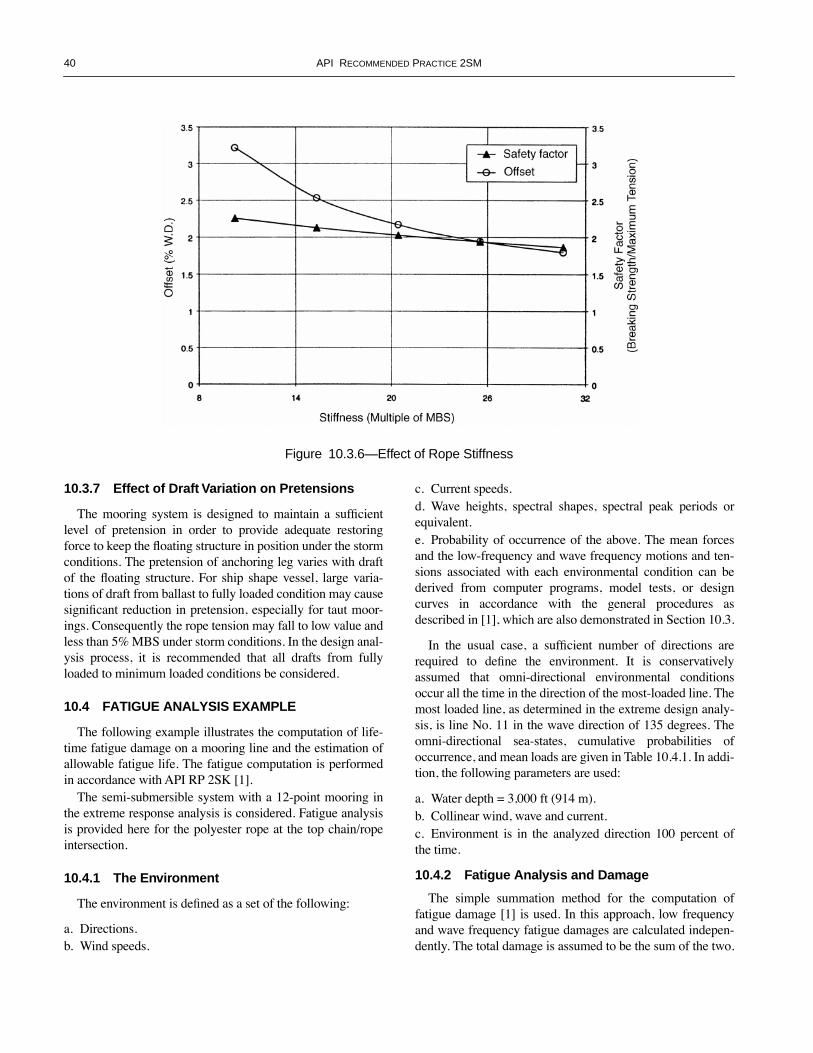
40 API RECOMMENDED PRACTICE 2SM
10.3.7 Effect of Draft Variation on Pretensions
The mooring system is designed to maintain a sufÞcientlevel of pretension in order to provide adequate restoringforce to keep the ßoating structure in position under the stormconditions. The pretension of anchoring leg varies with draftof the ßoating structure. For ship shape vessel, large varia-tions of draft from ballast to fully loaded condition may causesigniÞcant reduction in pretension, especially for taut moor-ings. Consequently the rope tension may fall to low value andless than 5% MBS under storm conditions. In the design anal-ysis process, it is recommended that all drafts from fullyloaded to minimum loaded conditions be considered.
10.4 FATIGUE ANALYSIS EXAMPLE
The following example illustrates the computation of life-time fatigue damage on a mooring line and the estimation ofallowable fatigue life. The fatigue computation is performedin accordance with API RP 2SK [1].
The semi-submersible system with a 12-point mooring inthe extreme response analysis is considered. Fatigue analysisis provided here for the polyester rope at the top chain/ropeintersection.
10.4.1 The Environment
The environment is deÞned as a set of the following:
a. Directions.b. Wind speeds.
c. Current speeds.d. Wave heights, spectral shapes, spectral peak periods orequivalent.e. Probability of occurrence of the above. The mean forcesand the low-frequency and wave frequency motions and ten-sions associated with each environmental condition can bederived from computer programs, model tests, or designcurves in accordance with the general procedures asdescribed in [1], which are also demonstrated in Section 10.3.
In the usual case, a sufÞcient number of directions arerequired to deÞne the environment. It is conservativelyassumed that omni-directional environmental conditionsoccur all the time in the direction of the most-loaded line. Themost loaded line, as determined in the extreme design analy-sis, is line No. 11 in the wave direction of 135 degrees. Theomni-directional sea-states, cumulative probabilities ofoccurrence, and mean loads are given in Table 10.4.1. In addi-tion, the following parameters are used:
a. Water depth = 3,000 ft (914 m).b. Collinear wind, wave and current.c. Environment is in the analyzed direction 100 percent ofthe time.
10.4.2 Fatigue Analysis and Damage
The simple summation method for the computation offatigue damage [1] is used. In this approach, low frequencyand wave frequency fatigue damages are calculated indepen-dently. The total damage is assumed to be the sum of the two.
Figure 10.3.6—Effect of Rope Stiffness

DESIGN, MANUFACTURE, INSTALLATION, AND MAINTENANCE OF SYNTHETIC FIBER ROPES FOR OFFSHORE MOORING 41
The damages are estimated using the RMS values of thelow frequency and wave frequency tensions, the polyesterrope fatigue characteristics, and the number of wave fre-quency and low-frequency tension cycles per year.
Although fatigue characteristics of large polyester ropesare not well established, available data and experience indi-cate that typical polyester ropes have tension/tension fatiguecharacteristics at least as good as comparable wire ropes insalt water. Further discussions on this subject can be found in4.6.7.2. For the current design example, the tension/tensionfatigue characteristics equivalent to that of the six-strand rope[1] is chosen in the fatigue analysis.
The frequency domain method of dynamic analysis intro-duced in 10.3 is used. Suitable values of polyester rope stiff-ness shall be chosen to account for the wave and low
frequency tensions. Assuming that fatigue damage is largelydominated by wave, the storm stiffness is used to provide aconservative approach.
A detailed computation of the fatigue damage per year asso-ciated with a 135-degree direction (wave heading towards), forline No. 11 is given in Table 10.4.2 for the polyester rope seg-ment. The total annual accumulated fatigue damages is:
The useful fatigue life is computed as:Life = 1/(10D) years.
=16,115 yearsThe safety factor applied is 10, based on the design criteria given
in 5.3.3.
D 6.205 10 6д=
Table 10.4.2—Polyester Rope Segment Fatigue Damage
Sig. Wave Height ft(m)
Mean Tension
kips
RMS Tension
(Wave) kips
RMS Tension
(Low) kips
Number of Cycles (Wave)
Number of Cycles (Low)
Zero Cross\ Period (wave)
Zero Cross Period Wave
Wave Frequency Damage
Low Frequency Damage
2.3(0.7) 484.1 0.3 0.2 3,929,175 253,003 4.98 77.34 3.87E-10 4.75E-126.0(1.8) 492.0 0.8 1.3 1,952,665 130,531 5.17 77.34 1.06E-08 5.17E-099.9(3.0) 504.5 1.4 2.7 267,776 20,042 5.79 77.36 1.44E-08 1.58E-08
13.8(4.2) 515.4 2.7 3.4 37,066 3,540 7.39 77.37 2.92E-08 7.16E-0917.8(5.4) 526.1 5.5 3.0 5,525 665 9.31 77.38 7.99E-08 8.05E-1021.8(6.6) 544.8 10.7 4.1 1,203 171 11.02 77.43 2.64E-07 7.44E-1026.0(7.9) 578.5 18.1 10.8 229 35 11.97 77.54 4.33E-07 8.09E-0930.0(9.1) 615.6 27.2 20.0 113 19 12.86 77.65 1.13E-06 5.31E-0834.0(10.4) 655.3 36.2 28.4 63 11 13.53 77.78 2.02E-06 1.30E-0737.9(11.6) 705.4 46.0 35.1 22 4 14.33 78.05 1.89E-06 1.15E-0742.6(13.0) 743.3 59.6 39.8 10 2 15.21 78.31 2.56E-06 9.54E-08


43
APPENDIX A—TESTING OF ROPE WET STRENGTH
A.1 Test Specimen Five specimens should be tested. The specimens should be terminated in the same manner as
that which will be used on the rope assembly, including thethimble design as described in 6.2.7.3. The specimen lengthshould be at least 40 times nominal rope diameter betweenrope ends of terminations.
The specimen should not have been previously tensionedto more than 5% of its estimated breaking strength nor havebeen cycled or maintained under tension.
The entire specimen including terminations should besoaked in fresh water for 22 and 26 hours before testing. Thespecimen should be tested as soon as practical after beingremoved from the water. If there is a delay of more than 12hours after soaking, the specimen is to be soaked again for anadditional 2 hours for each 24 hour period of delay up to amaximum of an additional 24 hours of soaking before therope is tested. The temperature of the water should be main-tained between 15¡ and 25¡ C (59¡ and 77¡ F).
A.2 Test Machine The test machine should have sufÞcient bed length, stroke,
rate of loading, and force producing capacity to carry out thetest as described in one pull without pause. The test machineshould be equipped with a force measuring and indicating/recording device which is accurate to within ± 1% of the esti-mated breaking force for the rope specimen. The force mea-suring and indication/recording device should be calibratedby a recognized independent calibration agency, using a ref-erence load cell traceable to applicable national standards.This calibration should have been done within the previousyear. An original calibration certiÞcate should be available forexamination, and a copy of this certiÞcate should be attachedto the test report.
A.3 Test Procedure The specimen should be tested for wet break strength in
accordance with ÒDetermination of Cycled StrengthÓ fromthe latest edition of CI 1500 ÒStandard Test Methods for FiberRopeÓ [23] as follows:
1. Cycle the rope ten times from 1% of estimated MBS(initial tension) to 50% of estimated MBS at the ratedescribed below. 2. On the eleventh cycle, apply force to the rope at therate described below until it breaks. 3. Record the breaking force (maximum force applied tothe rope). Record the point at which the rope broke, e.g.,between splices, at end of splice, at crotch of splice, inback of eye, or other description of break location. Therate of travel of the pulling head during the break testshould be such that the rope is loaded to 20% of its esti-mated MBS in not less than 2 sec. nor more than 30 sec.The crosshead should then continue moving withoutpause at approximately that rate of travel until the ropebreaks.
A.4 Data Reporting The breaking tension and the location and nature of break
should be reported for each specimen. The average wet breakstrength and the standard deviation of wet break strength areto be calculated, using the data from all Þve tests, andreported. Standard deviation should be computed by the n-1formula. The minimum wet break strength, deÞned as theaverage wet break strength minus two times the standarddeviation of wet break strength, should be calculated andreported.


45
APPENDIX B—TESTING OF ROPE ELONGATION AND MODULUS
B.1 Testing of Rope Wet Extension and Creep Properties
The extension data are intended to be used in mooring linepretension calculations and platform offset calculations. Theshapes of the load-extension curves at 6 min., 60 min., 600min. and 6000 min. may be extrapolated on a semi-log basis(elongation point on normal scale vs. time on log scale) tolonger times.
The creep data is intended to be used in mooring line creeptake-up calculations. The percent creep at 6 min., 60 min.,600 min. and 6000 min. may be extrapolated on a semi-logbasis (creep on normal scale vs. time on log scale) to longertimes.
B.1.1 TEST SPECIMEN
One specimen should be tested.It is not necessary that the terminations used in this test be
the same as those which will be used on the rope in service;however, the terminations should be of sufÞcient strength tosafely withstand at least 70% of the MBS.
The length of the specimen should be sufÞcient to accom-modate a gage length determined as follows:
The gage length over which elongation is measured shouldbe sufÞcient to achieve ±10% accuracy for the expectedextension [17, Attachment 6/B]. This criterion should bejudged by the accuracy to which the extension measuring sys-tem can measure the difference between rope length (overgage length) at trough load and at peak load for the intendedcyclic load range.
The gage marks should be no closer than 5 times ropediameter from the rope ends of termination. Thus the speci-men length should be sufÞcient to accommodate the gagelength, as determined above, plus at least 10 times nominalrope diameter between rope ends of terminations.
The specimen should not have been previously tensionedto more than 5% of its estimated MBS nor have been cycledor maintained under tension.
The specimen should be conditioned in water asdescribed in A.1.
B.1.2 TEST MACHINE AND APPARATUS
The test machine should be as described in A.2.In addition, the test machine should be equipped with an
elongation measuring device and data collection system capa-ble of measuring and recording the elongation over the gagelength determined above. The data collection system shouldbe capable of recording sufÞcient data points during a loadcycle to accurately determine the secant tangent between ten-sions separated by no more than 5% of the breaking strengthof the specimen.
The entire rope section including terminations is preferablyto be immersed in fresh water during the test. Alternatively,the entire length of rope between ends of terminations can besprayed with fresh water during the test at a minimum rateper minute calculated by the following formula:
where
WR = rate of water application, liter/min,
WL = length of rope over which water is applied, meters,
D = rope diameter, mm.
The water temperature should be maintained at between 5¡and 10¡C (41¡ and 50¡F).
B.1.3 TEST PROCEDURE
The specimen should be tested for wet elongation, exten-sion, and creep properties as follows:
1. Tension the rope to 1% of MBS (initial tension). Mea-sure and record the original initial length between gagemarks.
2. Tension the rope to 30% of MBS while recording elon-gation vs. tension. This tensioning should be done at the rateof crosshead travel established in A.3 (Appendix A).
3. Hold tension at 30% of MBS for 30 minutes.4. Reduce tension to 25% of MBS. Maintain this tension
for 6 minutes and then record the elongation of the rope atthis tension.
5. Lower rope tension to 1% of MBS. Measure and recordimmediate initial length between gage marks. With minimaldelay, retention it to 30% of MBS while recording elongationvs. tension. This lowering and retensioning should be done atthe rate of crosshead travel used in Step 2. Then lower tensionto 25% of MBS and maintain this tension.
6. Maintain the rope at 25% of MBS tension for a total of 1hour (54 additional minutes), adjusting tension as necessaryto maintain it at 25% ± 2% of MBS. At the end of 1 hourrecord elongation at 25% of MBS.
7. Repeat Step 5.8. Maintain the rope at 25% of MBS tension for a total of
10 hours (9 additional hours), adjusting tension as necessaryto maintain it at 25% ± 2% of MBS. At the end of 10 hoursrecord elongation at 25% of MBS.
9. Repeat Step 5.10. Maintain the rope at 25% of MBS tension for a total of
100 hours (90 additional hours), adjusting tension as neces-
WR 0.0004 W L D2´´=

46 API RECOMMENDED PRACTICE 2SM
sary to maintain it at 25% ± 2% of MBS. At the end of 100hours record elongation at 25% of MBS.
11. Repeat Step 5, then lower tension to zero to completethe test.
B.1.4 DATA REPORTING
Tabulate the elongation at 5% of MBS load incrementsfrom 5% to 30% of MBS for the Þrst tensioning and for theretensionings after 0.1 hr (6 min.), 1, 10 and 100 hours by thefollowing formula:
where
LL = Length of gaged portion of rope at designated load,
Li = Immediate initial length of gaged portion of rope at initial tension before application of des-ignated tension (Step 5).
For each elongation, calculate the percent extension by thefollowing equation:
where
Ext = Extension
Determine the extension at 25% of MBS tension afterrelaxing from the 30% of MBS tension and waiting for 6 min-utes (Step 4). Report this value as the lower postinstallationstiffness.
Plot extension vs. tension on the 1st tensioning and theretensionings after 0.1 hr (6 min.), 1, 10 and 100 hours.Report the load-extension plots.
Calculate the rope creep at 25% of MBS (as recordedbefore relaxing rope) after 0.1 hr (6 min.), 1, 10 and 100hours as percent of initial length by the following formula:
where
LO = Original initial length of gaged portion of rope at initial tension before application of any higher tension (Step 1).
Plot the rope creep after 0.1 hr (6 min.), 1, 10 and 100hours on semi-log graph paper with time in minutes on thelogarithmic scale. Fit a straight line through the data. If theplot is nonlinear, then Þt the straight line through the laterdata points only. Determine the creep over one log cycle from
the slope of this line. (Alternatively, a suitable curve-Þt equa-tion may be used).
Report the creep vs. log time plot and the percent creep perlog cycle.
These data can be extrapolated to estimate the creep whichwill occur over longer time intervals. These data can also beextrapolated to estimate the static load-extension characteris-tics after longer times.
B.2 Testing of Rope Wet Modulus Properties
B.2.1 TEST SPECIMEN
One specimen should be tested.The specimen should be terminated as described in B.1.1.The length of the specimen should be sufÞcient to accom-
modate a gage length determined as described in B.1.1.The specimen should not have been previously tensioned
to more than 5% of its of MBS nor have been cycled or main-tained under tension.
The specimen should be conditioned in water asdescribed in A.1.
B.2.2 TEST MACHINE AND APPARATUS
The test machine should be as described in A.2 and B.1.2.The entire rope section including terminations is preferably
to be immersed in fresh water during the test. Alternatively,the entire length of rope between ends of terminations can besprayed with fresh water at the rate described in B.1.2.
The water temperature should be maintained between 5¡Cand 10¡C (41¡ and 50¡F).
B.2.3 TEST PROCEDURE
The specimen should be tested for wet dynamic elongationand extension properties in accordance with Section 12ÒDetermination of Cycled Elongation and ExtensionÓ of CI1500-97 ÒStandard Test Methods for Fiber RopeÓ [23], modi-Þed as follows:
1. Tension the rope to 1% of MBS (initial tension). Mea-sure and record the original initial length between gagemarks.
2. Tension the rope to 55% of MBS while recording elon-gation vs. tension. This tensioning should be done at the rateof crosshead travel established in A.3 (Appendix A).
3. Hold tension at 55% of MBS for 30 minutes. Thenreduce tension to 25% of MBS.
4. Maintain tension on the rope at 25% of MBS for 6 min-utes and then record the elongation at this tension.
5. Lower rope tension to 1% of MBS. Measure and recordthe immediate initial length. With minimal delay, retension itto 55% of MBS while recording elongation vs. tension. This
Elg LL LiÐ=
Ext 100% Elg( ) Li¤´=
C 100% LL LOÐ( )´ LO¤=

DESIGN, MANUFACTURE, INSTALLATION, AND MAINTENANCE OF SYNTHETIC FIBER ROPES FOR OFFSHORE MOORING 47
lowering and retensioning should be done at the rate of cross-head travel used in Step 2. Then lower tension to 25% of MBS.
6. Cycle the rope about 25% of MBS mean tension with atension amplitude of 5% of MBS at a rate of 5 ± 1 cycles perminute (0.083 Hz). Record the rope elongation on the 1st,10th, 100th, and 1000th cycle while maintaining the samecycling rate.
7. After the 10th and 100th cycle, repeat Step 5. After the1000th cycle, proceed as follows.
8. Lower rope tension to 1% of MBS. Measure and recordthe immediate initial length. With minimal delay, retension itto 55% of MBS while recording elongation vs. tension. Thislowering and retensioning should be done at the rate of cross-head travel used in Step 2. Then lower tension to 40% ofMBS.
9. Cycle the rope about 40% of MBS mean tension with atension amplitude of 15% of MBS at a period of not less than1 cycle per minute. Record the rope elongation on the1,010th, 1100th and the 2000th cycle while maintaining thesame cycling rate.
10. After the 1,010th and 1,100th cycle, repeat Step 8.11. After the 2000th cycle, lower rope tension to 1% of
MBS. Measure and record the immediate initial length. Withminimal delay, retension it to 55% of MBS while recordingelongation vs. tension. This lowering and retensioning shouldbe done at the rate of crosshead travel used in Step 2. Thenreduce tension to zero to complete the test.
These cycles should be applied without signiÞcant pausesor interruptions.
B.2.4 DATA REPORTING
Calculate extension, as described in B.1.4.Determine the extension at 25% of MBS tension after
relaxing from the 55% of MBS tension and waiting for 6 min-utes (Step 4).
Plot and report installation extension vs. tension on the 1stcycle. Report this value as the higher post installation stiffness.
Plot and report dynamic extension vs. tension on the 1st,10th, 100th, and 1000th cycle.
Plot and report dynamic extension vs. tension on the1010th, 1100th, and 2000th cycle.
On a semi-log graph, plot the extensions at 5% of MBS (onnormal scale ordinate) against number of cycles (on log scaleabscissa). Repeat for extensions at 10%, 15%, 20%, 25%,30%, 35%, 40%, 45%, 50%, and 55% of MBS.
For the purpose of calculating modulus, the stress in therope is calculated by dividing tension by the rope Þber area.Calculate the rope Þber area by the following formula:
where
rfA = rope Þber area, mm,
Wf = mass of Þber per unit length of rope, kg/m,
Df = mass density of Þber material, g/cc.
For the purpose of calculating modulus, the strain in therope is calculated by dividing elongation (change in length)by gage length. Strain can also be determined by dividingextension by 100%.
For the purpose of calculating dynamic modulus, use thesecant slope (slope of the line joining the trough (lower) andpeak (upper) cyclic loads. Secant modulus is determinedinstead of tangent modulus because it can be determinedmore uniformly and accurately.
Calculate the secant modulus between the extensions at20% of MBS tension and 30% of MBS tension on the 1000thcycle. Report this as the intermediate modulus.
Calculate the secant modulus between the extensions at25% of MBS tension and 55% of MBS tension on the 2000thcycle. Report this as the storm modulus.
The dynamic moduli are intended to be used in dynamicmooring analysis. The dynamic moduli at 10th, 100th, and1000th cycle can be extrapolated on a semi-log basis (modu-lus on normal scale vs. cycles on log scale) to more cycles.
rfA 1 000, Wf Df¤´=


49
APPENDIX C—TESTING OF ROPE TENSION-TENSION FATIGUE QUALIFICATION
This test is intended to demonstrate that the synthetic ropehas a fatigue equivalence represented by one of the designcurves listed in 4.6.7.2, and the design equation can subse-quently be applied in the fatigue design of the rope. As speci-Þed in 6.3.6, the following testing parameters should beutilized for this purpose:
C.1 Test SpecimenOne specimen should be tested.The specimen should be terminated in the same manner as
intended for production ropes. The specimen length should bea minimum of 50 times nominal rope diameter between ropeends of terminations.
The specimen should be conditioned in water as describedin A.1.
C.2 Test Machine and ApparatusThe rope should be tested on a tension test machine with a
bed length, stroke, rate of loading, and force capacity sufÞ-cient to carry out the tests as described.
The entire rope section including terminations is preferablyto be immersed in fresh water during the test. Alternatively,the entire length of rope between ends of terminations can besprayed with fresh water at the rate described in B.1.2.
The water temperature should be maintained at between 5¡and 10¡C (41¡ and 50¡F).
Thermal couples or other suitable temperature measuringdevices should be placed Þrmly on the rope and insulatedfrom the water bath.
C.3 Test ProcedureThe cyclic load test should be conducted as follows:1. Cycle the rope about a mean tension of 30% of MBSwith a tension amplitude of 15% of MBS at a period ofless than 1 minute per cycle.2. If the surface temperature of the rope exceeds 70¡C(158¡F), suspend cycling and allow the rope to relax whilethe water bath continues until its surface temperature fallsto within 10¡C of the temperature of the water bath.3. Continue cycling for at least 30,000 cycles to qualifyfor the six/multi-strand-rope design curve; or at least80,000 cycles to qualify for the spiral-strand-rope designcurve; or at least 380,000 cycles to qualify for the polyes-ter rope design curve.
C.4 Rope Post Test ExaminationAfter cycling, examine the entire length of the rope includ-
ing termination in detail for any pending failure. A break testmay also be conducted to determine the residual strength ofthe rope.
C.5 Data ReportingRecord the number of applied cycles and signs of deterio-
ration, if any.Synthetic ropes which pass the 30,000-cycle test may
apply the six/multi-strand-rope design curve equation asdescribed in API RP 2SK [1].
Synthetic ropes which pass the 80,000-cycle test mayapply the spiral-strand-rope design curve equation asdescribed in API RP 2SK [1].
Synthetic ropes which pass the 380,000-cycle test may
Design Curve
Minimum Number of Cycles
Mean Tension
(% MBS)
Tension Amplitude (%MBS)
Polyester Rope 380,000 30 15Spiral Strand Equivalent 80,000 30 15Six/Multiple Strand Equivalent 30,000 30 15


51
APPENDIX D—TESTING OF ROPE AXIAL COMPRESSION PERFORMANCE
This test for axial compression performance should be car-ried out if the low tension design criteria in 5.3.2 are to bedeviated from.
D.1 Test Specimen
One specimen should be tested.The specimen should be terminated in the same manner as
intended for production ropes. The specimen length should bea minimum of 40 times nominal rope diameter between ter-minations.
The specimen should be conditioned in water as describedin A.1.
D.2 Test Machine and Apparatus
The rope should be tested on a tension test machine with abed length, stroke, rate of loading, and force capacity sufÞ-cient to carry out the tests as described.
The entire rope section including terminations is preferablyto be immersed in fresh water during the test. Alternatively,the entire length of rope between ends of terminations can besprayed with fresh water at the rate described in B.1.2.
The water temperature should be maintained at between 5¡and 10¡C (41¡ and 50¡F).
Thermal couples or other suitable temperature measuringdevices should be placed Þrmly on the rope and insulatedfrom the water bath.
D.3 Test ProcedureThe cyclic load test should be conducted as follows:1. Cycle the rope from a trough tension of 1% of MBS to a
peak tension of 25% of MBS at a period of less than 1 minuteper cycle.
2. If the surface temperature of the rope exceeds 70¡C(158¡F), suspend cycling and allow the rope to relax whilethe water bath continues until its surface temperature falls towithin 10¡C of the temperature of the water bath.
3. Continue cycling for at least 10,000 cycles.4. Tension the rope to break, using the test procedure of
A.3, to determine residual strength.
D.4 Data ReportingReport the residual strength, both in absolute terms and as
a percent of new MBS.Report the number of applied cycles.If there is no reduction in MBS, then the rope may be
classed to endure the demonstrated axial compressionfatigue cycles.


53
APPENDIX E—COMMENTARY ON MARINE FINISH
E.1 Commentary to 4.2.3.1Addressing the characteristics, use and speciÞcation of
marine Þnishes for deepwater moorings is complicated by anumber of factors:
¥ While the effectiveness and durability of marine Þn-ishes for short-term use is established, the long-term(greater than several years) durability has not been con-Þrmed by test data.
¥ Marine Þnish technology is considered highly propri-etary and has historically been subject to reÞnementwithout notiÞcation to the end-user.
¥ For permanent moorings (e.g., ßoating production sys-tems), the marine Þnish is thought to minimize Þber-to-Þber abrasion during the one-time initial bedding-inperiod, but its importance in increasing the long-termservice life has not been proven.
¥ For temporary moorings (e.g., MODUs) the long-termeffectiveness of the marine Þnish is considered to bemore important due to frequent recoveries and rede-ployments.
As an alternative to the testing called out in 4.2.3, proto-type rope certiÞcation fatigue testing may be done withoutthe marine Þnish (but with the normal spin Þnish) applied tothe Þbers. Performing fatigue tests without the marine Þnishdoes not lessen the importance of the marine Þnish, butavoids short-term fatigue results being skewed by a marineÞnish which may not be effective for the entire Þeld deploy-ment duration; however, results of such testing may or maynot be conservative because of the compounding effect ofmarine Þnish on the relative breaking strength (and thus refer-ence test loads) of the ropes.
E.2 Commentary to 4.2.3.2Demonstrating the long-term durability and effectiveness
of marine Þnishes can be a complex undertaking. The meth-ods used to measure effectiveness may be quite different thanthose methods used to measure durability. In addition, themost appropriate measures for durability may be materialdependent, so that a method that works well for one Þnishtype is not effective for a second Þnish type. Methods ofaccelerated testing can also skew Þnish comparisons by trig-gering chemical mechanisms in one Þnish technology notpresent in others.
The simplest measure of Þnish effectiveness is whether itenhances the yarn-on-yarn abrasion resistance of the yarn.This metric can be monitored after long-term seawater expo-
sure to indirectly observe physical or chemical changes in theÞnish or the yarn-Þnish interface caused by the seawater envi-ronment. This is a performance-based test that is much lessopen to interpretation as compared to chemical measure-ments.
Another simple measure of Þnish effectiveness is whetherit stays on the yarn over time (durability). Solvent extractionmethods can be used after seawater exposure if the assump-tion is made that the solvent(s) used in the extraction processremove all the marine Þnish components from the Þber orrope sample. In this case comparing the weight of the controland extracted samples gives the amount of marine Þnishremaining on the yarn. More complex chemical techniquessuch as FTIR, GC-MS or X-ray spectroscopy will providemore accurate measures of Þnish level but require elaborateanalytical facilities and higher testing budgets. Many of thesemethods also presume a prior knowledge of the chemistry ofthe Þnish being analyzed.
Several pitfalls should be avoided with strictly chemicalanalyses.
Note: Solvents can be Þnish-speciÞc, i.e., solvents that are effectiveremoving one type of Þnish or Þnish component may be poor atremoving other types or components. The Þbers themselves mayreact with certain solvents and release polymeric compounds thatwill be misinterpreted as Þnish components.
Also, some Þnishes may contain components that are sacri-Þcial or act as carriers for more active components. In suchcases the abrasion resistance of the Þbers will remain higheven as the total amount of extractable material is observed todecrease over time.
The chemistry of marine Þnish dissolution or removal byseawater will not be linear in time. Like most chemical pro-cesses, reaction rate is determined by activation energy andwill proceed logarithmically. For this reason, long-term (>20year) marine Þnish stability will most likely be determined bythe reaction in the Þrst 5% of the design life (one year). Test-ing beyond this timeline is unlikely to produce any furtherreaction in the material.
Accelerated testing methods need further development foruse in Þnish analysis. Simply using warm seawater may pro-duce changes in the seawater, the Þnish, or the Þnish/Þberinterface that could skew test results. Other methods foraccelerating Þnish removal such as ultrasonics or thermo-chemical should be viewed with caution until their effective-ness as compared with more traditional methods isestablished.


55
APPENDIX F—REFERENCES
API RP 2SK, Recommended Practice for Design andAnalysis of Stationkeeping Systems for Floating Struc-tures, Second Edition, API, March 1, 1997.
NDE/TTI Joint Industry Study ÒEngineers Design Guidefor Deepwater Þber MooringsÓ including Design Prac-tice Document and Engineering Commentary, FirstEdition, January 1, 1999. (OPL Publication).
NDE/TTI Joint Industry Study ÒÞber Tethers 2000, HighTechnology Þbers for Deepwater Tethers,Ó Phase 1,NDE/NEL/TTI, Noble Denton Report L17317/NDE/rwps, February 10, 1995 with Rev 1 additions datedJune 20, 1995.
ÒGlossary of Marine Fiber Rope Terms,Ó Task Committeeon Marine Fiber Rope of the Waterway, Port, Coastaland Ocean Division of the American Society of CivilEngineers (1993).
Chaplin C.R., Del Vecchio C.J.M., ÒAppraisal of Light-weight Moorings for Deep Water Applications,Ó OTC6965 (1992).
Bosman, R.L.M., ÒOn The Origin of Heat Build up inPolyester Rope,Ó IEEE 1986.
OCIMF: Guide to Purchasing Hawsers, Published byWitherby & Co. Ltd, London on behalf of OCIMF(1987).
OCIMF: Procedures for Quality Control and Inspectionduring Production of Hawsers, Published by Witherby& Co. Ltd, London on behalf of OCIMF (1987).
OCIMF: Prototype Rope Testing, Published by Witherby &Co. Ltd, London on behalf of OCIMF (1987).
ÒAdmiralty Manual of Seamanship Volume 1,Ó B.R. 67(1),Her MajestyÕs Stationery OfÞce (1964).
ÒAdmiralty Manual of Seamanship Volume 2,Ó B.R. 67(2),Her MajestyÕs Stationery OfÞce (1967).
ÒFiber Rope Testing 1995Ð97 Final Report Phase 1 and2ÑA Study into the Mechanical Properties and HeatBuild-up Characteristics of Small Scale and Full ScalePolyester and Aramid Rope,Ó Norsk Hydro JIP (1997).
Parsey, M.R., ÒFatigue of SPM Mooring Hawsers,Ó PaperNo. 4307, Offshore Technology Conference, Houston,May 1982.
Flory, J.F., ÒAvoiding Fiber Axial Compression Fatigue inthe Design and Use of Tension Members,Ó IEEE, 1986(pg 93Ð104).
Goksoy and Hearle, ÒYarn on Yarn Abrasion Testing ofRope Yarns. Part III: The Inßuence of Aqueous Envi-ronments,Ó J. Textile Inst. 79 443Ð450.
Berteaux, H.O., Prindle, B, Putman, S., ÒMonitoring Fish-bite Activities and Protecting Synthetic Þber RopesUsed in Deepsea Moorings,Ó 1993.
ÒGuidance Notes on the Application of Synthetic Ropesfor Offshore Mooring,Ó March 1999, American Bureauof Shipping.
ÒGuidance Notes for CertiÞcation of Synthetic Þber Ropesfor Mooring Systems,Ó Document Reference NI 432DTO R00 E, Bureau Veritas, Paris La Defense, 1997.
ÒCertiÞcation of Offshore Mooring Þber Ropes,Ó DetNorsk Veritas (1998) CertiÞcation Note 2.13, Draft inProgress, 1998.
ÒFiber Ropes in Offshore Mooring Systems,Ó Lloyds Reg-ister (1999), LR Report OS/TR/97008, Rev. B, Draft inProgress, March 1999.
ISO 2307, Ropes—Determination of Certain Physical andMechanical Properties, Second Edition, 1990-09-15,ISO 1990.
ISO EN919, Fiber Ropes for General Service. Determina-tion of Certain Physical and Mechanical Properties,BSI, 1995.
CI Standard Test Methods for Fiber Rope, CI 1500-97, TheCordage Institute, Hingham, MA.
ÒCordage Institute High Tenacity Fibers Chart,Ó CI 2003-98(Publication pending), Cordage Institute, Hingham, MA.
Firth, K.M., and Sefton, S.L., ÒThe Installation of SpiralStrand Mooring Cables in Deep Water,Ó Bridon Struc-tural Systems, Technical Report, Bridon, Doncaster,October 1997.
API RP 2I, Recommended Practice for In-Service Inspec-tion of Mooring Hardware for Floating Drilling Units,Second Edition, API, February 1, 1997.
IBC 2nd Annual Conference on ÒContinuous Advances inMooring and Anchoring,Ó June 2, 1997.
API RP 2FP1, Recommended Practice for Design, Analy-sis and Maintenance of Moorings for FloatingProduction Systems, API, First Edition, February 1993.
Test Method, Yarn-on-Yarn Abrasion, Wet and Dry, CIStandard 1503-99, Cordage Institute, Hingham, MA.
Lee, Ming-Yao, Devlin Paul and Kwan Chi-Tat Tho-mas, ÒDevelopment of API RP 2SM for SyntheticFiber Rope Moorings,Ó OCT 12178 (2000).
EQE International, ÒPolyester Moorings Reliability andData Uncertainty AssessmentÓ


RP 2T, Planning, Designing, and Constructing Tension Leg Platforms
Invoice To (❏ Check here if same as “Ship To”)
Name:
Title:
Company:
Department:
Address:
City: State/Province:
Zip/Postal Code: Country:
Telephone:
Fax:
E-Mail:
❏ Payment Enclosed ❏ P.O. No. (Enclose Copy)
❏ Charge My Global Account No.
❏ VISA ❏ MasterCard ❏ American Express ❏ Discover
Credit Card No.:
Name (As It Appears on Card):
Expiration Date:
Signature:
Quantity Product Number Title Total
Subtotal
Applicable Sales Tax (see below)
Rush Shipping Charge (see below)
Shipping and Handling (see below)
Total (in U.S. Dollars)
*To be placed on Standing Order for future editions of this publication, place a check mark in the SO column and sign here:
Pricing and availability subject to change without notice.
Date:
SO* Unit Price
American Petroleum Institute Related Publications Order Form - 2001
❏ API Member (Check if Yes)
Ship To (UPS will not deliver to a P.O. Box)
Name:
Title:
Company:
Department:
Address:
City: State/Province:
Zip/Postal Code: Country:
Telephone:
Fax:
E-Mail:
Available through Global Engineering DocumentsPhone Orders: 1-800-854-7179 (Toll-free in the U.S. and Canada) • 303-397-7956 (Local and International) • Fax Orders: 303-397-2740Online Orders: www.global.ihs.com
G2AWSD RP 2A-WSD, Planning, Designing, and ConstructingFixed Offshore Platforms—Working Stress Design
$200.00
G02C05 $ 77.00
Mail Orders – Payment by check or money order in U.S. dollars is required except for established accounts. State and local taxes, plus 5% for shipping and handling, must be added.Send mail orders to: API Publications, Global Engineering Documents, 15 Inverness Way East, M/S C303B, Englewood, CO 80112-5776, USA.Purchase Orders – Purchase orders are accepted from established accounts. Invoice will include actual freight cost, an $8.00 handling fee, plus state and local taxes.Telephone Orders – If ordering by telephone, an $8.00 handling fee and actual freight costs will be added to the order.Sales Tax – All U.S. purchases must include applicable state and local sales tax. Customers claiming tax-exempt status must provide Global with a copy of their exemptioncertificate.Shipping (U.S. Orders) – Orders shipped within the U.S. are sent via traceable means. Most orders are shipped the same day. Subscription updates are sent by First-Class Mail.Other options, including next-day service, air service, fax transmission, and electronic delivery are available at additional cost.Shipping (International Orders) – Standard international shipping is by air express courier service. Subscription updates are sent by World Mail. Normal delivery is 3-4 days fromshipping date.Rush Shipping Fee – In addition to the carrier charges, the following charges will be added: Next Day Delivery orders placed prior to 2:00 p.m. MST - $10.00 / Next Day Deliveryorders placed after 2:00 p.m. MST - $20.00 (if time is available for order processing)Returns – All returns must be pre-approved by calling Global’s Customer Service Department at 1-800-624-3974 for information and assistance. There may be a 15% restocking fee.Special order items, electronic documents, and age-dated materials are non-returnable.
Spec 2C, Offshore Cranes
G02D04 RP 2D,Operation and Maintenance of Offshore Cranes $ 88.00
$ 61.00Spec 2F, Mooring ChainG02F06
G02RD1 RP 2RD, Design of Risers for Floating Production (FPSs)and Tension-Leg Platforms (TLPs)
$ 149.00
G02SK2 RP 2RSK, Design and Analysis of Stationkeeping Systemsfor Floating Structures
$ 132.00
G02ST $ 132.00G02N02 RP 2N, Planning, Designing, and Constructing Structures and Pipelines for Arctic Conditions $ 99.00

03/01

Additional copies are available through Global EngineeringDocuments at (800) 854-7179 or (303) 397-7956
Information about API Publications, Programs and Services isavailable on the World Wide Web at: http://www.api.org
Order No. XXXXXXProduct