SYNTHETIC APERTURE RADAR (SAR) SIGNAL … APERTURE RADAR (SAR) SIGNAL ... Abstract—This paper...
22
Progress In Electromagnetics Research B, Vol. 1, 269–290, 2008 SYNTHETIC APERTURE RADAR (SAR) SIGNAL GENERATION Y. K. Chan and S. Y. Lim Faculty of Engineering & Technology Multimedia University Jalan Ayer Keroh Lama, Bukit Beruang, Melaka 75450, Malaysia Abstract—This paper outlines the trend of signal generation in synthetic aperture radar particularly chirp (linear FM signal) generation using digital approach. A study in fundamental of FM signal and typical analog FM signal generation is highlighted. Various signal generation in SAR using digital techniques is discussed and finally the some of the digital chirp generators are presented. 1. INTRODUCTION Radar has long been used for military and non-military purposes in a wide variety of applications such as imaging, guidance, remote sensing and global positioning [1]. Airborne and spaceborne radars, capable of producing images of ground, have been developed and extensively used in remote sensing applications. In the 1950s, Real Aperture Imaging Radar (or Side Looking Airborne Radar, SLAR) was developed to produce better quality images for military use. Large antenna that produces narrow radiation beamwidth must be used for scanning of the earth terrain in order to achieve the required resolution. However, the image formed by SLAR is poor in azimuth resolution. The recent development in Synthetic Aperture Radar (SAR) technology has made possible a much higher resolution to be achieved using a small antenna. The advantages of SAR have been detailed in many books and journals, which record the concrete proof and support behind the blossoming of SAR systems in worldwide [2]. Among them includes fine resolution achievable that made headline when the technique first came to light, often credited to Carl Wiley of Goodyear Aerospace in 1951 [3]. SAR has been shown to be very useful over a wide range of applications, including high resolution geological and topological mapping, snow monitoring [4], military surveillance,
Transcript of SYNTHETIC APERTURE RADAR (SAR) SIGNAL … APERTURE RADAR (SAR) SIGNAL ... Abstract—This paper...
Progress In Electromagnetics Research B, Vol. 1, 269–290, 2008
SYNTHETIC APERTURE RADAR (SAR) SIGNALGENERATION
Y. K. Chan and S. Y. Lim
Faculty of Engineering & TechnologyMultimedia UniversityJalan Ayer Keroh Lama, Bukit Beruang, Melaka 75450, Malaysia
Abstract—This paper outlines the trend of signal generationin synthetic aperture radar particularly chirp (linear FM signal)generation using digital approach. A study in fundamental of FMsignal and typical analog FM signal generation is highlighted. Varioussignal generation in SAR using digital techniques is discussed andfinally the some of the digital chirp generators are presented.
1. INTRODUCTION
Radar has long been used for military and non-military purposesin a wide variety of applications such as imaging, guidance, remotesensing and global positioning [1]. Airborne and spaceborne radars,capable of producing images of ground, have been developed andextensively used in remote sensing applications. In the 1950s, RealAperture Imaging Radar (or Side Looking Airborne Radar, SLAR) wasdeveloped to produce better quality images for military use. Largeantenna that produces narrow radiation beamwidth must be usedfor scanning of the earth terrain in order to achieve the requiredresolution. However, the image formed by SLAR is poor in azimuthresolution. The recent development in Synthetic Aperture Radar(SAR) technology has made possible a much higher resolution to beachieved using a small antenna. The advantages of SAR have beendetailed in many books and journals, which record the concrete proofand support behind the blossoming of SAR systems in worldwide [2].Among them includes fine resolution achievable that made headlinewhen the technique first came to light, often credited to Carl Wiley ofGoodyear Aerospace in 1951 [3]. SAR has been shown to be very usefulover a wide range of applications, including high resolution geologicaland topological mapping, snow monitoring [4], military surveillance,
270 Chan and Lim
mining [5], hydrology, oil pollution monitoring [6], classification ofearth terrain [7] etc. The potential of SAR in a diverse range ofapplication led to the development of a large number of airborne andspaceborne SAR systems.
One breakthrough in technology made up the advancement of SARdevelopment is to take the digital approach towards designing anddeveloping of the transmitter for SAR. The idea of taking the digitalapproach is rooted in the belief that, as for most contemporary radarsystems designs, digital electronics offer better stability, repeatability,and flexibility over an equivalent analog upshot. This revolution inradar designs has over the decades justified the common perceptionof many radar designers about radar system, that unlike early radarsystems that consisted entirely of analog circuits, digital techniquescan now be employed too for optimization purpose. In fact, thereare several other advantages of digital circuits in comparison withanalog circuits, such as, digital circuits are less affected by noise and itcan be regenerated to achieve lossless data transmission. Also, digitaloperations interface well with computers and are easy to control withsoftware. This is particularly advantageous because timing circuitsthat could be interfaced with control unit of SAR system are neededto properly control chirp start frequency in an effort to preserve thecoherency of SAR system. SAR being a coherent system requires boththe magnitude and the phase of the echo samples to be preserved,which implies that the system pulse-to-pulse phase must be stable asthe essential information lies not in the magnitude but the phase of thereceived data. Apart from that, information storage by digital methodis much easier than using analog methods and this is a plus for radarreceiver whereby data storing is involved.
Nevertheless, despite the many advantages offered by digitalcircuitry, generation of chirp signal directly at the intermediatefrequency (IF) by digital method was in the olden days possible butnot popular. This was due to the limitation in the speed of thedigital circuitry as well as the demand for high clock frequency tomeet the Nyquist Theorem. Nyquist Theorem states that a signalmust be sampled at least twice as fast as the bandwidth of the signalto accurately reconstruct the waveform; otherwise, the high-frequencycontent will alias at a frequency inside the spectrum of interest, whichis the so-called passband. Although a lowpass filter could be adoptedin an effort to prevent aliasing in the passband, in that it limit thefrequency content of the input signal above the Nyquist rate, but thebest is still to have sampling rate twice as that of the bandwidth forbest performance.
These two constraints had long remained restrictive to SAR design
Progress In Electromagnetics Research B, Vol. 1, 2008 271
in the past, until very recently the restriction is lifted when they havebeen proven neither insurmountable nor insuperable because the speedof digital circuitry has increased remarkably following advances indigital technology. Though it is often uncertain whether technologyor customer demand is driving the other, technology advancementis no doubt an essential part of SAR technology and hence itsdevelopment. That explains why generation of chirp signal directlyat baseband is today favoured for it avoids the difficulties of buildinga precision single-sideband modulator with high suppression of carrierand unwanted sideband.
In reality, for the past 30 years or so a large proportion of theinnovation in radar systems arose from the use of digital technologyin radar systems design, notably among them is in data processing.Indeed in recent years many radar designers have been switching —if not already switched — to the adopting of digital techniques thatfurther contributed to the mushrooming of various digital techniquesin SAR application all across the globe. This trend is expectedto continue, with advances in radio frequency (RF) technology andantennas, besides digital technology. In brief, a digital world beckons.
The digital approach taken to construct the chirp generator islimited to the state-of-the-art in digital components in the market. Itrelies heavily on the best components the market has to offer, in termsof speed, precision and resolution (for instance, that of DAC). Howeverdigital circuits are also subject to the following limitations:
• Digital circuits are more likely to include human error as theyare more complex. That explains why much of the modern art ofdesigning digital systems consists of analyzing them into smallerparts that can be perfectly solved with some form of automateddesign system.
• Digital systems can be fragile, in that the lost or misinterpretationof a single piece of digital data can result in a thorough changeof meaning of large blocks of related data. Anyhow, this problemcan be mitigated by designing the digital system for robustness.A crucial issue is to remove unused logic signals in minimizing thenumbers of states.
• Quantizations errors may be present as the analog signals fromthe real world are translated into a storable, regenerable digitalform. Yet this problem can normally be mitigated by storing moredigital data within practical limit.
• Digital system could use subtle features to store digital states thatdigital systems errors are difficult to be regenerated accurately.In most digital circuits, these problems show up as “glitches”,
272 Chan and Lim
vanishingly-fast pulses that may trigger some logic but notothers, “runt pulse” that do not reach valid switching (threshold)voltages, or unexpected (“undecoded”) combinations of logicstates.
• Digital circuits are slower to perform calculations than analogcircuits using similar components.
• Digital circuits are sometimes more expensive, especially in smallquantities.
Nonetheless, despite the limitations discussed above, digitaltechnology has been proven time and again to be of great significancein stirring the innovations in radar systems design especially in recentyears. Literally, these limitations can be overlooked as they do notaffect the kernel of the system. After all, many of the limitationsdescribed above have their own alternatives to overcoming it, whichfurther reduces the impact of its weak points. Thus, exaggerating thelimitations of digital circuitry under microscope is unnecessary.
2. CHIRP SIGNAL ANALYSIS
In general, chirp is a typical phase coding or modulation applied to therange pulse of imaging radars designed to achieve high time bandwidthproduct (TBP). The resulting phase is quadratic in time, which hasa linear derivative, hence the name linear frequency modulation, orlinear FM. There is a solid reason as to why linear FM has becomeso dominant and widely adopted in various SAR systems design allover the world today. Early radar systems transmitted a strong pulseof RF energy after which it displayed reflections of the pulse on thefamiliar circular display screen, the scanning beam of which matchedthe angle of the rotating dish antenna. The phosphor blip, whichis a spot of light on the radar screen indicating the position of adetected object, appeared at a radial distance from the screen centerdirectly proportional to delay time of the reflected signal, and thereforeits distance. Their peak power levels and pulse widths however,limited range and resolution of these fixed-frequency pulse systemsrespectively. Although resolution could be improved by narrowingthe pulse, but this reduced the outgoing peak energy resulting incompromised range performance, and also required wider bandwidthoperation for both the transmitter and receiver systems. This morasshad remained baffling for some time, until pulse compression techniquecame to light.
Pulse compression is a technique that helps overcome the abovementioned limitations in an effective manner. It is no wonder this
Progress In Electromagnetics Research B, Vol. 1, 2008 273
technique is used in virtually all radar systems nowadays, not justin SAR. Instead of a fixed frequency pulse, the transmitted pulse ismodulated by a specific phase or frequency pattern during a widerpulse interval. The receiver uses a pulse-matched filter to pass reflectedpulses that match the pattern of the outgoing pulse and reject noiseand other signals. In other words, a form of correlation is implementedby the pulse-matched filter in the receiver to produce a narrow outputpulse only when the received signal contains the exact frequency chirppattern in the transmit pulse. Since the transmitted pulse is wider,a lower peak power output stage can deliver the same amount oftransmitted pulse energy to maintain range performance. In this way,the wide transmitter pulse is effectively compressed to a narrow pulseat the output of the correlator. The ratio of the transmitted pulse tothe compressed pulse, known as the pulse compression ratio, is equalto BW·PW, where BW is the bandwidth of the sweep and PW is thetransmitter pulse width.
To avoid confusion however, it must be pointed out that pulsecompression technique does not make up to pulse modulation. Instead,it constitutes to frequency modulation, with the name chirp, or linearfrequency sweep. Typically there are three basic modulation schemes inradar system, namely pulse, linear FM (LFM) chirp, and phase coded.Frequency modulation is conventionally selected over pulse modulationfor its easier signal processing and simpler yet economical hardwareimplementation. Unlike pulse radar that separates the transmitted andreceived signals in the time domain, the LFM radar transmits chirpsignal at lower power yet processes the received signal in frequencydomain, thereby eliminating the need for proper and very precisetiming circuitry. Also, LFM radar has no need of a high power sourceas in pulse radar to generate a short burst of electromagnetic energy.In fact the same average transmitting power can be achieved with lowerpeak amplitude in typical LFM radars. As a matter of fact, the use offrequency modulation to obtain range information in radar is almostas old as radar itself, dating back to 1924 when Appleton and Barnettused this technique for ionospheric sounding [8].
In the time domain, an ideal linear FM signal or pulse has aduration T seconds with a constant amplitude, a center frequencyfcen Hz, and a characteristic phase component θ(t), which varies withtime in a specific manner [9]. Physical “probing” systems oftentransmit pulses of this form. For linear frequency modulation, thephase is a quadratic function of time. When fcen is set to zero, thecomplex form of the signal is
s(t) = rect
(t
T
)exp
jπKt2
(1)
274 Chan and Lim
where t is the time variable in seconds, while K is the linear FM ratein hertz per second. Each of the real and imaginary parts oscillates asa function of time, and the oscillation frequency increases away fromthe time origin.
On the other hand, the phase of the pulse is given by the argumentof the exponential expressed in radians
φ(t) = πKt2 (2)
This equation is a quadratic function of time.As for the instantaneous frequency, it is the derivative with respect
to time expressed in Hz, implying that the frequency is a linear functionof time t, with the slope K expressed in hertz per second.
f =12π
dφ(t)dt
=12π
d(πKt2)dt
= Kt (3)
The bandwidth is defined as the range of frequencies spanned bythe significant energy of the chirp, or the frequency excursion of thesignal (for real signals, only positive frequencies are considered in thisdefinition). The bandwidth is the product of the chirp slope andthe chirp duration, expressed in Hertz, and it governs the obtainableresolution.
BW = |K|T (4)
Another signal parameter is the time bandwidth product (TBP),which presents the product of the bandwidth |K|T and chirp durationT (a dimensionless parameter).
TBP = |K|T 2 (5)
The TBP of the baseband linear FM signal in (1) can be measured bycounting the number of zero crossings of the real or imaginary part ofthe time-domain signal. When fcen = 0, the number of zero crossings inthe signal is close to one-half of the TBP. For T of 20 us and bandwidthof 20 MHz, it gives a TBP of 400.
In short, a linear FM signal has a quadratic phase, where itsfrequency is a linear function of time. The frequency slope is the linearFM rate. A linear FM signal is often called a chirp, in analogy with abird’s call. When the slope is positive, the signal is called an up chirp;whereas for a negative slope, the signal is called a down chirp. Yet thedirection of the chirp, which is embedded in the sign of K, will notaffect the analysis.
Progress In Electromagnetics Research B, Vol. 1, 2008 275
2.1. Spectrum of the Linear FM Pulse
Most pulse compression radars require a drive signal for the poweramplifier which has an essentially rectangular envelope. For a linearFM signal the associated frequency spectrum is also approximatelyrectangular, based on a derivation of the Fourier Transform of thesignal. The exact derivation is not straightforward, but a convenientapproximate expression can be obtained by the Principle of StationaryPhase (POSP).
There are a couple of important properties that can be derivedfrom the complex spectrum of a linear FM pulse. First, the real andimaginary parts of the spectrum have a similar linear FM structureas the real and imaginary parts of the time domain signal. Thedifferences are a π/4 phase change, and a change in the sign of theFM rate, compared to the time domain. Second, the envelope of themagnitude of spectrum is approximately the same as the rectangularenvelope of the time domain signal. In other words, the envelope isapproximately preserved between the two domains. And third, thephase of the spectrum is approximately quadratic in the frequencydomain, as it is in the time domain. This implies that the frequencyversus time relationship is f = Kt, showing that there is a linear, one-to-one relationship between time and frequency in linear FM signals.
This problem statement stems from the limitations revolvinganalog FM modulation technique that has been in use worldwide for atleast two decades, due to its simplicity and low cost implementation.Traditional FM exciter technology makes full use of a modulatedoscillator approach to FM generation. In principal, a FM signalis obtained by forcing an oscillator to move in proportional toa modulation frequency, which is normally done by applying amodulation signal to a varactor that is part of an oscillator’s tankcircuit. The varactor is a semiconductor device in which thecapacitance is sensitive to the applied voltage at the boundary ofthe semiconductor material and an insulator. As for the tank circuit,its center frequency changes as the modulation voltage changes. Thefrequency of oscillation will then change too following changes in thecenter frequency. An equation that describes the resultant signal canbe stated as below:
FM(t) = A cos[ωc + kffm(t)]t + θ0 (6)
A close examination on the above equation reveals that itresembles very much the equation used to digitally generate FM signal.In this equation, A refers to the amplitude of the FM signal or peakvoltage output of the oscillator. The center frequency of oscillation canbe obtained from ω/2π, while the constant kf has units of rad/sec/volt
276 Chan and Lim
and relates to how much the frequency changes for a given voltageinput. As for θ0, it represents the initial phase of the signal whilefm(t) speaks for the modulation signal.
XTAL
OSC. M φ LPF +
N
Analog Modulation
Channel Selection
Phase Detector
MF F
F
Tuning Voltage
VCO
NF
PA
FM OUT
÷
÷
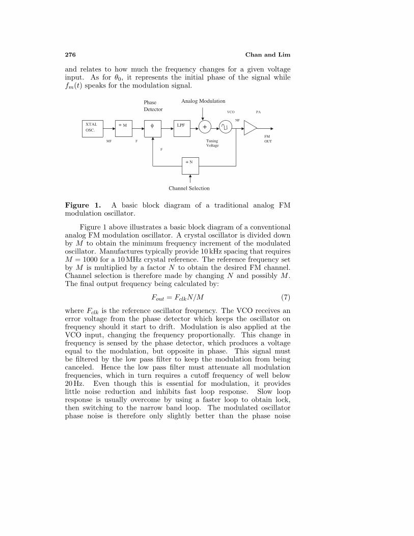
Figure 1. A basic block diagram of a traditional analog FMmodulation oscillator.
Figure 1 above illustrates a basic block diagram of a conventionalanalog FM modulation oscillator. A crystal oscillator is divided downby M to obtain the minimum frequency increment of the modulatedoscillator. Manufactures typically provide 10 kHz spacing that requiresM = 1000 for a 10 MHz crystal reference. The reference frequency setby M is multiplied by a factor N to obtain the desired FM channel.Channel selection is therefore made by changing N and possibly M .The final output frequency being calculated by:
Fout = FclkN/M (7)
where Fclk is the reference oscillator frequency. The VCO receives anerror voltage from the phase detector which keeps the oscillator onfrequency should it start to drift. Modulation is also applied at theVCO input, changing the frequency proportionally. This change infrequency is sensed by the phase detector, which produces a voltageequal to the modulation, but opposite in phase. This signal mustbe filtered by the low pass filter to keep the modulation from beingcanceled. Hence the low pass filter must attenuate all modulationfrequencies, which in turn requires a cutoff frequency of well below20 Hz. Even though this is essential for modulation, it provideslittle noise reduction and inhibits fast loop response. Slow loopresponse is usually overcome by using a faster loop to obtain lock,then switching to the narrow band loop. The modulated oscillatorphase noise is therefore only slightly better than the phase noise
Progress In Electromagnetics Research B, Vol. 1, 2008 277
of the VCO. Also, since lower frequencies are attenuated less, itsresponse is degraded. Another problem due to the narrow bandwidthof the modulation oscillator is susceptibility to microphonics. Unlessadequate mechanical isolation is provided, microphonic frequenciesabove a few Hertz will impact system noise performance.
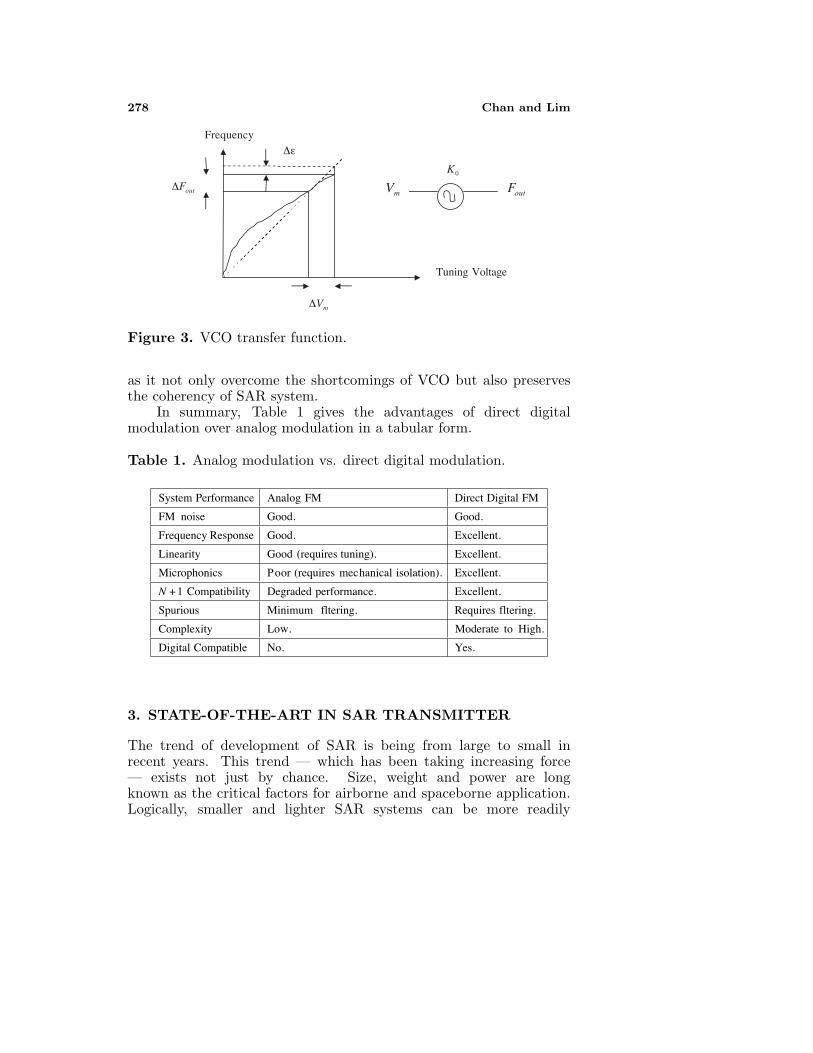
Additionally, system performance is impacted by the non-linearityin the VCO itself. The transfer function of the VCO can be describedby the following equation:
K0 = ∆Fout/∆Vm (8)
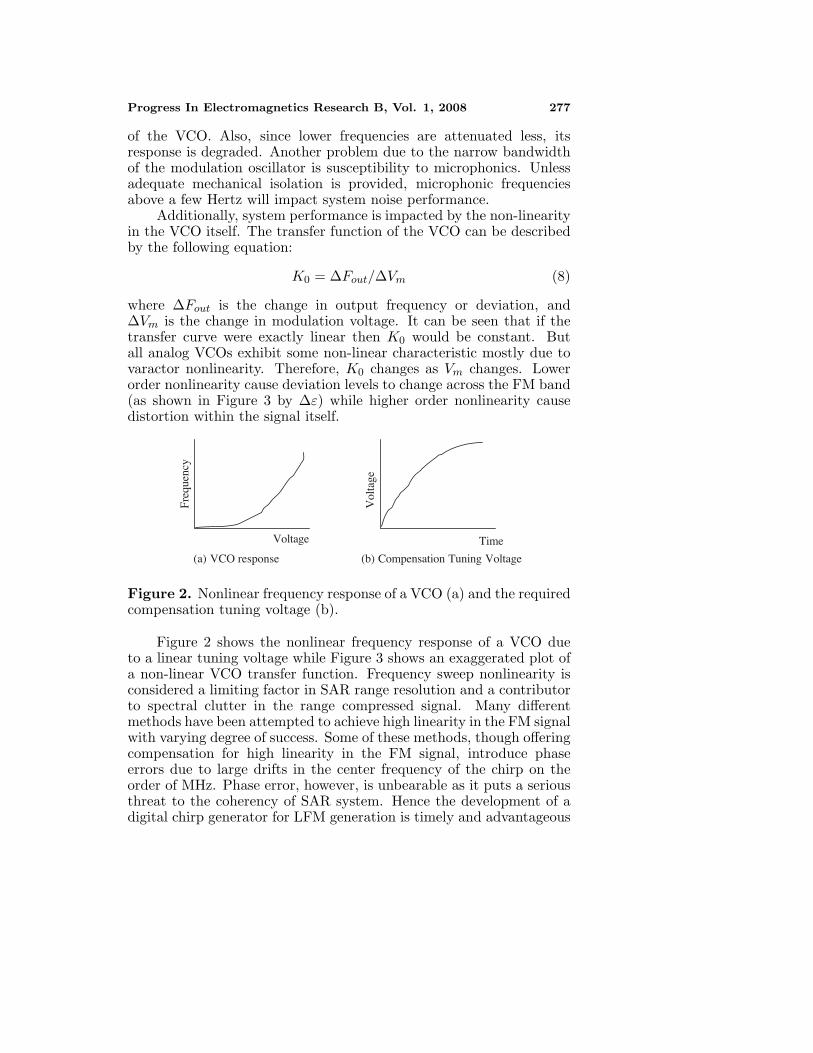
where ∆Fout is the change in output frequency or deviation, and∆Vm is the change in modulation voltage. It can be seen that if thetransfer curve were exactly linear then K0 would be constant. Butall analog VCOs exhibit some non-linear characteristic mostly due tovaractor nonlinearity. Therefore, K0 changes as Vm changes. Lowerorder nonlinearity cause deviation levels to change across the FM band(as shown in Figure 3 by ∆ε) while higher order nonlinearity causedistortion within the signal itself.
(a) VCO response
TimeVoltage
(b) Compensation Tuning Voltage
Freq
uenc
y
Vol
tage
Figure 2. Nonlinear frequency response of a VCO (a) and the requiredcompensation tuning voltage (b).
Figure 2 shows the nonlinear frequency response of a VCO dueto a linear tuning voltage while Figure 3 shows an exaggerated plot ofa non-linear VCO transfer function. Frequency sweep nonlinearity isconsidered a limiting factor in SAR range resolution and a contributorto spectral clutter in the range compressed signal. Many differentmethods have been attempted to achieve high linearity in the FM signalwith varying degree of success. Some of these methods, though offeringcompensation for high linearity in the FM signal, introduce phaseerrors due to large drifts in the center frequency of the chirp on theorder of MHz. Phase error, however, is unbearable as it puts a seriousthreat to the coherency of SAR system. Hence the development of adigital chirp generator for LFM generation is timely and advantageous
278 Chan and Lim
mV∆
Tuning Voltage
Frequency
outF∆
ε∆
0K
mV
outF
Figure 3. VCO transfer function.
as it not only overcome the shortcomings of VCO but also preservesthe coherency of SAR system.
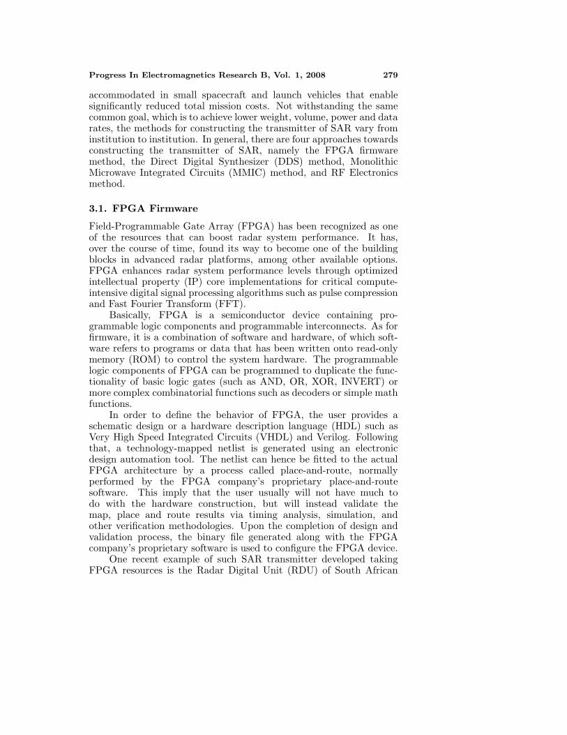
In summary, Table 1 gives the advantages of direct digitalmodulation over analog modulation in a tabular form.
Table 1. Analog modulation vs. direct digital modulation.
System Performance Analog FM Direct Digital FM
FM noise Good. Good.
Frequency Response Good. Excellent.
Linearity Good (requires tuning). Excellent.
Microphonics Poor (requires mechanical isolation). Excellent.
N + 1 Compatibility Degraded performance. Excellent.
Spurious Minimum fltering. Requires fltering.
Complexity Low. Moderate to High.
Digital Compatible No. Yes.
3. STATE-OF-THE-ART IN SAR TRANSMITTER
The trend of development of SAR is being from large to small inrecent years. This trend — which has been taking increasing force— exists not just by chance. Size, weight and power are longknown as the critical factors for airborne and spaceborne application.Logically, smaller and lighter SAR systems can be more readily
Progress In Electromagnetics Research B, Vol. 1, 2008 279
accommodated in small spacecraft and launch vehicles that enablesignificantly reduced total mission costs. Not withstanding the samecommon goal, which is to achieve lower weight, volume, power and datarates, the methods for constructing the transmitter of SAR vary frominstitution to institution. In general, there are four approaches towardsconstructing the transmitter of SAR, namely the FPGA firmwaremethod, the Direct Digital Synthesizer (DDS) method, MonolithicMicrowave Integrated Circuits (MMIC) method, and RF Electronicsmethod.
3.1. FPGA Firmware
Field-Programmable Gate Array (FPGA) has been recognized as oneof the resources that can boost radar system performance. It has,over the course of time, found its way to become one of the buildingblocks in advanced radar platforms, among other available options.FPGA enhances radar system performance levels through optimizedintellectual property (IP) core implementations for critical compute-intensive digital signal processing algorithms such as pulse compressionand Fast Fourier Transform (FFT).
Basically, FPGA is a semiconductor device containing pro-grammable logic components and programmable interconnects. As forfirmware, it is a combination of software and hardware, of which soft-ware refers to programs or data that has been written onto read-onlymemory (ROM) to control the system hardware. The programmablelogic components of FPGA can be programmed to duplicate the func-tionality of basic logic gates (such as AND, OR, XOR, INVERT) ormore complex combinatorial functions such as decoders or simple mathfunctions.
In order to define the behavior of FPGA, the user provides aschematic design or a hardware description language (HDL) such asVery High Speed Integrated Circuits (VHDL) and Verilog. Followingthat, a technology-mapped netlist is generated using an electronicdesign automation tool. The netlist can hence be fitted to the actualFPGA architecture by a process called place-and-route, normallyperformed by the FPGA company’s proprietary place-and-routesoftware. This imply that the user usually will not have much todo with the hardware construction, but will instead validate themap, place and route results via timing analysis, simulation, andother verification methodologies. Upon the completion of design andvalidation process, the binary file generated along with the FPGAcompany’s proprietary software is used to configure the FPGA device.
One recent example of such SAR transmitter developed takingFPGA resources is the Radar Digital Unit (RDU) of South African
280 Chan and Lim
Synthetic Aperture Radar II (SASAR II) in May 2004, by theDepartment of Electrical Engineering, University of Cape Town [10].This RDU — which is a subsystem of SASAR II — further contains oneDigital Pulse Generator (DPG), Sampling Unit (SU) and Timing Unit(TU). The firmware is designed and written using Mentor GraphicsHDL Designer — a tool specifically used for firmware development.ModelSim then simulates the firmware after the writing process whileSynplify synthesizes the firmware after simulation of the design.
Notwithstanding the advantages that FPGA bring, such as theimproved performance and increased speed, there are also certaintrades-off associated with FPGA inevitably. FPGA is generally moreexpensive and difficult to program as the programming involved is notjust writing a program but creating hardware. Also, it is less versatileand less flexible in that once written, or modified, the FPGA is toughto change again. Still, FPGA has found its place in applications likesonar, medical, baggage scanning, and radar — which includes SAR.The bottom line could be drawn, therefore, that FPGA is good forapplications where they sit on the front end, quickly doing compute-intensive work with simple algorithms.
3.2. Direct Digital Synthesizer
The Direct Digital Synthesizer (DDS), which is also known as theNumerically Controlled Oscillator (NCO), is seen adopted in modernradar systems. DDS is a technique that uses digital-data andmixed/analog-signal processing blocks as a means to generate real-life waveforms that are repetitive in nature. In principle, DDS isan electronic method for digitally creating arbitrary waveforms andfrequencies from a single, fixed source frequency. A basic DDScircuit consists of an electronic controller, a random-access memory,a frequency reference (normally a crystal oscillator), a counter and adigital-to-analogue converter (DAC).
DDS grew out of the military necessity for different kinds of radarable to sweep a frequency. Historically the military used DDS, yettheir brand of DDS was an expensive, large, rack-mounted instrumentthat would dissipate 50 watts. Then from radar applications DDSworked its way into becoming used as a general local oscillator incommunications systems. The DDS characteristics that most attractradar-system designers are precision frequency-tuning, phase offsetcontrol, and linear chirp capability. Since DDS is in basic a techniquefor creating a waveform in digital domain, it can generate waveformof any arbitrary nature — not just the common sine wave. Meaningwaveform can be created and put into an algorithm or a lookup tablethat will then be made repetitive. This accounts for the beauty of DDS
Progress In Electromagnetics Research B, Vol. 1, 2008 281
as it gives its designers control over every aspect of the waveform theyare generating.
One such example of the radar transceiver developed by thismethod, among many others, is the chirp synthesizer developedby the Electronic Communications Laboratory of the Universityof Florida, United States, in 1995 for applications in variousradar configurations [11]. This synthesizer allows the generationof waveforms with a wide range of carrier frequencies, chirp rate,pulse widths, and pulse repetition frequencies. The variation ofthese parameters allows the radar to transmit different waveformsto achieve various missions such as target acquisition, tracking, orclassification. This synthesizer’s flexible waveform control provides ameans for motion compensation, reducing ambiguities, and correctionof nonlinearities in the transceiver’s frequency response.
In short, DDS promises precise, agile control of output waveforms;but is limited in frequency and spurious performance. In other words,DDS has limited operating ranges and limited spectral purity dueto numerical distortions and actual realization. Other applicationsof DDS beside radar include satellite communications, broadbandnetworking, test and measurement, and instrumentation.
3.3. MMIC Technologies
The use of Monolithic Microwave Integrated Circuits (MMIC) inspace hardware is becoming more widespread lately. Besides, it hasalso successfully made its presence noticeable in automotive radarapplications and in its transceiver design. MMICs are integrated circuit(IC) devices that operate at microwave frequencies, which typicallyperform functions such as microwave mixing, amplification, and tuning.In essence, a MMIC is a microwave circuit in which the activeand passive components are fabricated on the same semiconductorsubstrate. The frequency of operation can range from 1 GHz to100 GHz, and a couple of different technologies and circuit approachescan be used. The additional term ‘monolithic’ is needed to distinguishthem from the established microwave integrated circuit (MIC), whichis a hybrid comprising a number of discrete active devices and passivecomponents integrated onto a common substrate using solder orconductive epoxy adhesive.
There are certain advantages and disadvantages associated withMMICs. MMICs are cheap in large quantities and hence economicalfor complex circuits. Also, they are small and light, reliable, and lessparasitic (more bandwidth); besides having very good reproducibility.Reproducibility is excellent for MMICs because the active and passivecomponents are produced by the same well-controlled fabrication steps,
282 Chan and Lim
using the same photolithographic masks. Nevertheless, despite offeringstrings of advantages, MMICs have very limited choice of component,require long turn around time (approximately 3 months) and are veryexpensive to start up. Furthermore, most MMIC devices have to betailored to volume production and tend not to give state-of-the-artperformance. This can be a serious problem for design that demandsexcellent performance, such as the design of Low Noise Amplifier(LNA) and Power amplifier (PA).
The applications of MMICs are wide, with military and spaceapplications being the major driving force behind MMIC technology.For instance, the Advanced RF & Optics Group at Matra MarconiSpace Systems Portsmouth, United Kingdom, has designed one T/RModule for their Advanced Synthetic Aperture Radar (A.S.A.R) usingGaAs MMIC circuits in 1998 [12]. This T/R Module that operatesat 5.3 GHz consists of a low noise receiver and a transmitter thatprovides peak output power of nominally 7.2 Watts. The T/R Moduleoperates between a single RF port and two radiator ports, namelythat of vertical and horizontal polarization. Since physical size andmass are equally important, GaAs MMICs have been incorporated inthe areas of phase, amplitude control, switching, and transmit channelamplification. Additionally, this project has also pioneered the use ofceramic packaging technologies that aimed at reducing mass.
Other applications of MMICs beside radar are in communicationssatellites, mobile phones, electronic warfare, radiometers, globalpositioning (GPS) and many others. It is interesting to be pointedthat there are a variety of applications for microwave/millimeter wavedevices in the consumer automotive arena. These include forwardlooking radar for collision warning and cruise control, side radar forlane change maneuvers, rear radar for backing aid, parking aid, airbag arming, and security systems.
3.4. RF Electronics
The RF Electronics method has been receiving warm welcomeespecially of late as it allows better creativity for the users to makedo on the current technology available besides keeping the cost low.Recognizing that maintenance costs could be reduced by reliabilityimprovements, ways of improving the installation’s transmitter systemsof radar have been studied in supporting the aging technology into thefuture. Engineers have determined that reliability, supportability, andreliability gains in the transmitter system could be realized throughmodern design approaches, like in the case of phased-array radar,high-power vacuum tubes are replaced with RF power transistor andintegrated electronic technology. Apart from that, microcontroller
Progress In Electromagnetics Research B, Vol. 1, 2008 283
with high integrated features can be employed to minimize assemblycomplexity and parts count. All these account for the fundamentaladvantage of electronic control, which is the speed.
One fine example that illustrates a transmitter brought aboutby this method, among many others, is the low cost, FM/CWtransmitter developed by the Microwave Earth Remote SensingLaboratory of Brigham Young University, in 2000 for use from 2to 18 GHz with a transmit bandwidth of up to 1 GHz [13]. Thisdesign includes a microcontroller aided by a 10 bit digital to analogconverter (DAC), a microwave VCO, a 4 bit counter, several radiofrequency (RF) prescalers, and a passive coplanar microwave circuit.The microcontroller communicates with a host using a RS232 serialport, enabling the users to set parameters such as center frequency,bandwidth and repetition count. A trigger is used to synchronizereceiver analog to digital conversions with the transmitted signal. Thistransmitter is adopted in a railway hazard detection system, a SAR,and an altimeter.
There are a variety of electronic technologies in the development ofupgrades or brand-new design of the transmitter of radar systems. Forinstance, high-voltage and high-power electronics, power grid tubes,RF power transistors, analog/digital electronics, RF signal processingelectronics, electronic packaging, and PC-based instrumentation areall at hand. In most cases, circuits are engineered using standardelectronic components; but in some cases, like RF amplifiers,commercial industry can be solicited for custom-developed productsbuilt to Institute’s specifications. As for RF signal processingcomponents, they can be represented by power dividers, mixers,filters, fixed attenuators, current-controlled variable attenuators, RFamplifiers, voltage-variable phase shifter, and some others. Deviceconnections can be made on a printed circuit board with microstripcircuit traces designed for 50-Ω transmission line impedance.
4. CHIRP GENERATOR IN SAR TRANSMITTER
Before applying chirp generator into the transmitter of SAR system,the selection of choice to developing the transmitter is first to be madeafter careful examination of the state-of-the-art in SAR transmitter,as presented in Section 3. This was so as the method chosen has directeffects on the method to developing chirp generator in the later stage.
Nevertheless, in spite of the selection made, it is crucial to bepointed out that the question of which is the better technology, orwhich performs the better does not arise. Each technology has itsplace — a place determined by the application and by individual needs.
284 Chan and Lim
Co-existence, rather than competition, is deemed the way forward.Each technology, be it FPGA, DDS, MMIC, or RF electronics, hasits advantages and disadvantages and each is capable, according tothe application, of outperforming the other. It doesn’t matter whichtechnology has been chosen, so long as it is capable to meet the designneeds. All the more so when the said technology can contributeto improving the performance, target acquisition, and tracking andidentification of the targets, like what many modern radar systemengineers are working on and seeking after.
4.1. State-of-the-Art in Chirp Generator
Chirp generator, which is also known as the Linear FrequencyModulation (LFM) generator, has witnessed the increasing usageof itself in recent years. Chirp pulses are required for a numberof earth remote sensing such as SAR, and Radar Altimeter (RA).Also, it may find its usage in planetary remote sensing spaceborneinstruments such as SAR, RA, and microwave sounder. To name afew, a Canadian National (CN) Railway funded project uses a LFMgenerator at C-band, or to be more exact, at 5.7 GHz to 6.0 GHztogether with interferometry to measure terrain profiles [14]. Besides, aNASA funded project uses the chirp transmitter that operates between14.2 GHz to 14.4 GHz to analyze the mean sea level EM bias in aprototype altimeter [15]. In fact, the increased usage of radar forcommercial products has shed light into the radar field thereby bringinghigher demand for a cost-effective chirp generator.
The performance requirements of chirp generator for differentapplications vary remarkably from 5 MHz/5 msec chirp rate forplanetary research, to 320 MHz/300µsec chirp rate for earthobservation advanced radar altimeter. This altimeter is commonlyused for determining elevation, especially an aneroid barometer usedin aircraft that senses pressure changes accompanying changes inaltitude. Though the performance requirements of chirp generator maybe different, but the basic operation is the same in all applications.Hence, the development of a single unit that can be configured to meeta range of requirements is advantageous and timely.
Study has revealed that a digital-based chirp generator hasadvantages of stability, repeatability and flexibility over an equivalentanalog solution. Principally, there are three basic approaches todigitally generating chirp pulses, namely dual adder, RAM/ROMbased (pre-stored waveform), and single bit methods.
Progress In Electromagnetics Research B, Vol. 1, 2008 285
4.1.1. Dual Adder Method
The dual adder method has reasonably low mass and power, whichmeets the trend of radar design as discussed in Section 3. Also,the start frequency implemented by this method can be properlycontrolled. Yet, though this method offers great flexibility and lowimplementation size for long pulses, but it offers limited bandwidthdue to the implementation technology. High bandwidth, however,is essential in this work as range resolution of SAR can be madearbitrarily fine by increasing the pulse bandwidth within practicallimits.
4.1.2. Single Bit Method
The single bit method, being simple in nature, requires less designingand developing time. Also, it allows very high bandwidth. Yet,it has unacceptable phase performance for it generates large phaseerrors at high frequencies. Apart from that, chirp start frequency ofthis method is uncontrollable, which makes designing a coherent SARsystem impossible. A point to be borne in mind when consideringwhich method to adopt is that, the clock frequency of the to-be-designed chirp generator will be derived from a single source, in thiscase from Stable Local Oscillator (STALO). In other words, controlover the start frequency of chirp signal is mandatory.
4.1.3. RAM/ROM based Method
The RAM/ROM based method is also known as the pre-storedwaveform method. This method promises low mass or power forsimple chirps. Though the characteristic of low mass or power mightbe restrictive for fine control of chirp start frequency or long pulses.The pre-stored waveform approach gives maximum performances forshort pulses; yet as the length of pulses increases, the memory sizewill increase linearly. In addition, the RAM/ROM based methodoffers high bandwidth which will improve with the speed of memorytechnology. Apart from that, non-linear ramps can be achieved withthis method, besides linear ramps.
4.2. Selection of Choice
Having surveyed the implementation of high time bandwidth chirppulses using three basic digital techniques, it can therefore beconcluded that by comparison the RAM/ROM based method outshinesall others in that it offers high bandwidth and linear ramps yet puts no
286 Chan and Lim
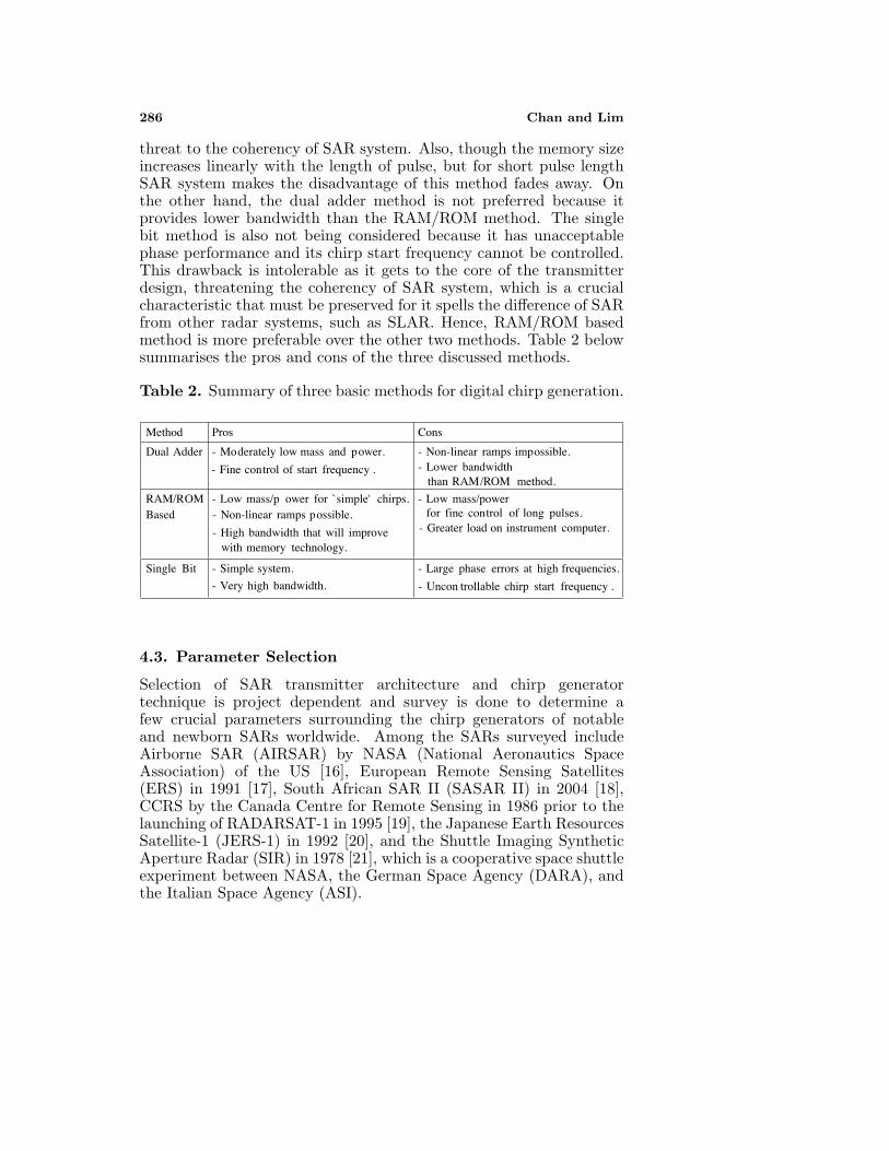
threat to the coherency of SAR system. Also, though the memory sizeincreases linearly with the length of pulse, but for short pulse lengthSAR system makes the disadvantage of this method fades away. Onthe other hand, the dual adder method is not preferred because itprovides lower bandwidth than the RAM/ROM method. The singlebit method is also not being considered because it has unacceptablephase performance and its chirp start frequency cannot be controlled.This drawback is intolerable as it gets to the core of the transmitterdesign, threatening the coherency of SAR system, which is a crucialcharacteristic that must be preserved for it spells the difference of SARfrom other radar systems, such as SLAR. Hence, RAM/ROM basedmethod is more preferable over the other two methods. Table 2 belowsummarises the pros and cons of the three discussed methods.
Table 2. Summary of three basic methods for digital chirp generation.
Method Pros Cons
Dual Adder - Moderately low mass and power.
- Fine control of start frequency .
- Non-linear ramps impossible.- Lower bandwidth
than RAM/ROM method.
RAM/ROMBased
- Low mass/p ower for `simple' chirps.- Non-linear ramps possible.
- High bandwidth that will improvewith memory technology.
- Low mass/powerfor fine control of long pulses.
- Greater load on instrument computer.
Single Bit - Simple system.
- Very high bandwidth.
- Large phase errors at high frequencies.
- Uncon trollable chirp start frequency .
4.3. Parameter Selection
Selection of SAR transmitter architecture and chirp generatortechnique is project dependent and survey is done to determine afew crucial parameters surrounding the chirp generators of notableand newborn SARs worldwide. Among the SARs surveyed includeAirborne SAR (AIRSAR) by NASA (National Aeronautics SpaceAssociation) of the US [16], European Remote Sensing Satellites(ERS) in 1991 [17], South African SAR II (SASAR II) in 2004 [18],CCRS by the Canada Centre for Remote Sensing in 1986 prior to thelaunching of RADARSAT-1 in 1995 [19], the Japanese Earth ResourcesSatellite-1 (JERS-1) in 1992 [20], and the Shuttle Imaging SyntheticAperture Radar (SIR) in 1978 [21], which is a cooperative space shuttleexperiment between NASA, the German Space Agency (DARA), andthe Italian Space Agency (ASI).
Progress In Electromagnetics Research B, Vol. 1, 2008 287
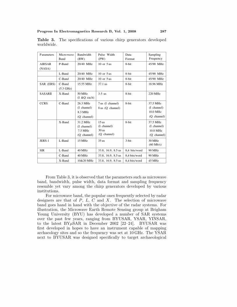
Table 3. The specifications of various chirp generators developedworldwide.
Parameters Micro waveBand
Bandwidth(BW)
Pulse Width(PW)
DataFormat
SamplingFrequency
AIRSAR
(NASA)
P-Band 20/40 MHz 10 or 5 us 8-bit 45/90 MHz
L-Band 20/40 MHz 10 or 5 us 8-bit 45/90 MHz
C-Band 20/40 MHz 10 or 5 us 8-bit 45/90 MHz
SAR (ERS) C-Band
(5.3 GHz)
15.55 MHz 37.1 us 8-bit 18.96 MHz
SASARII X-Band 50 MHz(I &Q each)
3-5 us 8-bit 220 MHz
CCRS C-Band 26.3 MHz(I channel)
8.3 MHz
(Q channel)
7 us (I channel)
8 us (Q channel)
8-bit 37.5 MHz(I channel)10.0 MHz
(Q channel)
X-Band 31.2 MHz(I channel)7.5 MHz(Q channel)
15 us(I channel)30 us(Q channel)
8-bit 37.5 MHz(I channel)
10.0 MHz(Q channel)
JERS-1 L-Band 15 MHz 35 us 3-bit 30 MHz(60 Mb/s)
SIR L-Band 40 MHz 33.8, 16.9, 8.5 us 8,4 bits/word 90 MHz
C-Band 40 MHz 33.8, 16.9, 8.5 us 8,4 bits/word 90 MHz
X-Band 10&20 MHz 33.8, 16.9, 8.5 us 8,4 bits/word 45 MHz
From Table 3, it is observed that the parameters such as microwaveband, bandwidth, pulse width, data format and sampling frequencyresemble yet vary among the chirp generators developed by variousinstitutions.
For microwave band, the popular ones frequently selected by radardesigners are that of P , L, C and X. The selection of microwaveband goes hand in hand with the objective of the radar systems. Forillustration, the Microwave Earth Remote Sensing group at BrighamYoung University (BYU) has developed a number of SAR systemsover the past few years, ranging from BYUSAR, YSAR, YINSAR,to the latest BYµSAR in December 2002 [22–24]. BYUSAR wasfirst developed in hopes to have an instrument capable of mappingarchaeology sites and so the frequency was set at 10 GHz. The YSARnext to BYUSAR was designed specifically to target archaeological
288 Chan and Lim
sites and so the frequency was lowered to 2.1 GHz for greater groundpenetration. In a separate development later, YINSAR was broughtabout on a Cessna 337 N Skymaster reconnaissance plane owned jointlyby the BYU and Utah State University. And the frequency was raisedback to 9.9 GHz again, approaching 10 GHz like that of BYUSAR formapping archaeology sites.
On the other hand, bandwidth and pulse width of the chirpgenerator determine range resolution and the location of the detectabletargets respectively. Higher bandwidth allows for better rangeresolution while wider pulse width increases the minimum distanceat which targets can be detected. This is so as wilder pulse deliversmore energy and results in stronger signal return for the receiver. Asfor the data format, although higher bit can result in better resolution,for instance 36-bit data yields better resolution than an 8-bit one, butone remark can be drawn from Table 3, that generally, data formatof 8 bits would be sufficient. The last parameter to be noted is thesampling frequency — it should preferably be set at a value to fulfillthe Nyquist Theorem for good performance.
5. CONCLUSION
With the development of modern integrated circuits technology,the technique for signal digitally generation are evolving rapidly tomaturity. The digital radar transmitter can obtain much higherprecision and stability than analog ones. Furthermore it can retain theextreme flexibility of digital techniques. The advent of digital radartransmitters is an evolution of modern SAR transmitter technology.This paper provided a brief introduction to the various architecturesemployed in SAR transmitter design and digital technique used in chirpgeneration. The merit and demerit for each of the digital generationtechnique has been discussed and each is capable, according to theapplication, of outperforming the other.
REFERENCES
1. Skolnik, M. I., Radar Handbook, McGraw-Hill, New York, 1970.2. Curlander, J. C. and R. N. McDounough, Synthetic Aperture
Radar, Systems and Signal Processing, John Wiley & Sons, NewYork, 1991.
3. Wiley, C. A., “Pulse doppler radar methods and apparatus,”United States Patent, No. 3, 196, 436, Filed, August 1954, 1965.
4. Storvold, R., E. Malnes, Y. Larsen, K. A. Hogda, S.-E. Hamran,
Progress In Electromagnetics Research B, Vol. 1, 2008 289
K. Mueller, and K. Langley, “SAR remote sensing of snowparameters in Norwegian areas — Current status and futureperspective,” Journal of Electromagnetic Waves and Applications,Vol. 20, No. 13, 1751–1759, 2006.
5. Lynne, G. L. and G. R. Taylor, “Geological assessment of SIR-B imagery of the Amadeus basin,” IEEE Trans on Geosc. andRemote Sensing, Vol. 24, Issue 4, 575–581, 1986.
6. Hovland, H. A., J. A. Johannessen, and G. Digranes, “Slickdetection in SAR images,” Proceeding of the 1994 InternationalGeoscience and Remote Sensing Symposium, 2038–2040, 1994.
7. Kong, J. A., S. H. Yueh, H. H. Lim, R. T. Shin, and J. J. vanZyl, “Classification of Earth terrain using polarimetric syntheticaperture radar images,” Progress In Electromagnetics Research,PIER 03, 327–370, 1990.
8. Goodman, J. M., Space Weather & Telecommunications, Springer,2005.
9. Cumming, I. G. and F. H. Wong, Digital Processing of SyntheticAperture Radar Data: Algorithms and Implementation, ArtechHouse, London, 2005.
10. Webster, J. M., “The development of a radar digital unit forthe SASAR II project,” Master Thesis, University of Cape Town,Cape Town, South Africa, 2004.
11. Adler, E. D., E. A. Viveiros, T. Ton, J. L. Kurtz, andM. C. Bartlett, “Direct digital synthesis applications for radardevelopment,” Radar Conference 1995, Issue 8–11, 224–226, 1995.
12. Hector, C., J. Brunt, and J. Arnold, “T/R module MMICcomponents for spaceborne SAR,” IEE Colloquium on Active andPassive Components for Phased Array Systems, 12/1–12/7, 1992.
13. Smith, R. L. and D.V. Arnold, “Development of a low cost,FM/CW transmitter for remote sensing,” Proceedings IEEE 2000International Geoscience and Remote Sensing Symposium, Vol. 5,2328–2330, 2000.
14. Waite, J. L. and D. V. Arnold, “Interferometric radar principlesin track hazard detection to improve safety,” Proc. IGARSS’00,Vol. 6, 2507–2509, Honolulu, 2000.
15. Zaugg, D. A., D. V. Arnold, and M. A. Jensen, “Oceansurface and landslide probing with a scanning radar altimeter,”Proceedings IEEE 2000 International Geoscience and RemoteSensing Symposium, Vol. 1, 120–122, 2000.
16. Held, D. N., W. E. Brown, A. Freeman, J. D. Klein,H. Zebker, T. Sato, T. Miller, Q. Nguyen, and Y. L. Lou,
290 Chan and Lim
“The NASA/JPL multifrequency, multipolarisation airborne SARsystem,” Proceeding of the 1988 International Geoscience andRemote Sensing Symposium, 345–349, 1988.
17. Way, J. and E. A. Smith, “The evolution of synthetic apertureradar systems and their progression to the EOS SAR,” IEEETransactions on Geoscience and Remote Sensing, Vol. 29, Issue 6,962–985, 1991.
18. Coetzer, D. G., “Design and implementation of a X-bandtransmitter and frequency distribution unit for a syntheticaperture radar,” Master Thesis, 2004.
19. Livingstone, C. E., A. L. Gray, R. K. Hawkins, and R. B. Olsen,“CCRS C/X-airborne synthetic aperture radar: An R&D tool forthe ERS-1 time frame,” IEEE Aerospace and Electronic SystemsMagazine, Vol. 3, 11–20, 1988.
20. Nemoto, Y., H. Nishino, M. Ono, H. Mizutamari, K. Nishikawa,and K. Tanaka, “Japanese earth resources satellite-1 syntheticaperture radar,” Proceedings of the IEEE, Vol. 79, Issue 6, 800–809, 1991.
21. Jordan, R. L., B. L. Huneycutt, and M. Werner, “The SIR-C/X-SAR synthetic aperture radar system,” IEEE Transactions onGeoscience and Remote Sensing, Vol. 33, Issue 4, 829–839, 1995.
22. Thompson, D. G., D. V. Arnold, and D. G. Long, “YSAR: Acompact, low-cost synthetic aperture radar,” Proceeding of the1996 International Geoscience and Remote Sensing Symposium,1892–1894, 1996.
23. Thompson, D. G., D. V. Arnold, D. G. Long, G. F. Miner, andM. A. Jensen, “YINSAR: A compact, low-cost interferometricsynthetic aperture radar,” Proceeding of International Geoscienceand Remote Sensing Symposium, 1920–1922, 1998.
24. Zaugg, E. C., D. L. Hudson, and D. G. Long, “The BYUmicroSAR: A small, student-built SAR for UAV operation,”Proceedings of the International Geoscience and Remote SensingSymposium, 2006.