Synthesis of finite state machines for improved state verification
15
Synthesis of finite state machines for improved state verification Imtiaz Ahmad * , Faridah M. Ali, A. Shoba Das Department of Computer Engineering, Kuwait University, P.O. Box 5969, Safat 13060, Kuwait Received 22 August 2005; accepted 5 December 2005 Available online 18 May 2006 Abstract Finite State Machines (FSMs) are used in diverse areas to model hardware and software systems. Verification of FSMs is essential to ensure reliability of systems. To verify that a machine is in an expected state in testing, Unique Input/Output (UIO) sequences are used. The aforementioned testing methodology requires that each state in the FSM has an UIO. How- ever, it is possible for a given machine that few or even none of its states have an UIO sequence. This paper presents a guided heuristic algorithm for synthesizing FSMs such that each state has an UIO sequence. The states of an FSM with identical I/O labels on transitions are grouped in order to identify the states which do not possess UIO sequence. The tran- sitions are then augmented by adding extra output terminals incrementally so that new UIO sequences are created for the states. A greedy approach is used to optimize the number of added outputs. Initially, the transitions which lead to state convergence (i.e., transitions with identical input/output labels taking a set of states to the same next state) and constrained self-loop (i.e., transitions taking a set of states either to itself or leads to state convergence) are identified since a state with only these transitions will never have a UIO sequence. Extra output terminals are added to the FSM which are used only while testing and the augmented output labels make sure that the states are neither convergent nor has constrained self- loop, thereby ensuring UIO sequence. The proposed algorithm, referred to as AUGP, was tested with a large number of FSMs including the Microelectronics Center of North Carolina (MCNC) FSM benchmarks. The augmented state transi- tion table was used as input to a UIO computation algorithm (developed by the same authors [Ahmad I, et al. IEE Proc Comput Digital Tech 2004;151(2):131]) to check the performance of the augmentation algorithm and the tested FSMs were found to possess UIO sequence for all states. Ó 2006 Elsevier Ltd. All rights reserved. 1. Introduction Finite State Machine (FSM) models are used extensively in variety of hardware computation structures such as sequential circuits in digital control systems, iterative networks, microprocessor control circuits, digital communication systems, etc. and in software applications such as lexical analysis, parsing, pattern 0045-7906/$ - see front matter Ó 2006 Elsevier Ltd. All rights reserved. doi:10.1016/j.compeleceng.2005.12.002 * Corresponding author. Tel.: +965 4811188x5849; fax: +965 4839461. E-mail address: [email protected] (I. Ahmad). Computers and Electrical Engineering 32 (2006) 349–363 www.elsevier.com/locate/compeleceng
-
Upload
imtiaz-ahmad -
Category
Documents
-
view
212 -
download
0
Transcript of Synthesis of finite state machines for improved state verification

Computers and Electrical Engineering 32 (2006) 349–363
www.elsevier.com/locate/compeleceng
Synthesis of finite state machines for improvedstate verification
Imtiaz Ahmad *, Faridah M. Ali, A. Shoba Das
Department of Computer Engineering, Kuwait University, P.O. Box 5969, Safat 13060, Kuwait
Received 22 August 2005; accepted 5 December 2005Available online 18 May 2006
Abstract
Finite State Machines (FSMs) are used in diverse areas to model hardware and software systems. Verification of FSMsis essential to ensure reliability of systems. To verify that a machine is in an expected state in testing, Unique Input/Output(UIO) sequences are used. The aforementioned testing methodology requires that each state in the FSM has an UIO. How-ever, it is possible for a given machine that few or even none of its states have an UIO sequence. This paper presents aguided heuristic algorithm for synthesizing FSMs such that each state has an UIO sequence. The states of an FSM withidentical I/O labels on transitions are grouped in order to identify the states which do not possess UIO sequence. The tran-sitions are then augmented by adding extra output terminals incrementally so that new UIO sequences are created for thestates. A greedy approach is used to optimize the number of added outputs. Initially, the transitions which lead to stateconvergence (i.e., transitions with identical input/output labels taking a set of states to the same next state) and constrainedself-loop (i.e., transitions taking a set of states either to itself or leads to state convergence) are identified since a state withonly these transitions will never have a UIO sequence. Extra output terminals are added to the FSM which are used onlywhile testing and the augmented output labels make sure that the states are neither convergent nor has constrained self-loop, thereby ensuring UIO sequence. The proposed algorithm, referred to as AUGP, was tested with a large number ofFSMs including the Microelectronics Center of North Carolina (MCNC) FSM benchmarks. The augmented state transi-tion table was used as input to a UIO computation algorithm (developed by the same authors [Ahmad I, et al. IEE ProcComput Digital Tech 2004;151(2):131]) to check the performance of the augmentation algorithm and the tested FSMs werefound to possess UIO sequence for all states.� 2006 Elsevier Ltd. All rights reserved.
1. Introduction
Finite State Machine (FSM) models are used extensively in variety of hardware computation structuressuch as sequential circuits in digital control systems, iterative networks, microprocessor control circuits,digital communication systems, etc. and in software applications such as lexical analysis, parsing, pattern
0045-7906/$ - see front matter � 2006 Elsevier Ltd. All rights reserved.
doi:10.1016/j.compeleceng.2005.12.002
* Corresponding author. Tel.: +965 4811188x5849; fax: +965 4839461.E-mail address: [email protected] (I. Ahmad).
350 I. Ahmad et al. / Computers and Electrical Engineering 32 (2006) 349–363
matching, neural networks, hypertext meta languages and the control portion of communication protocolspecification [1].
Verification of finite state machines has become essential in system design and implementation to make surethat the implementation conforms to the specification. A detailed survey on methods of testing FSMs is pre-sented in Refs. [1,2]. In testing procedures, given an FSM with its specification (A) and an implementation (B)whose I/O behavior only could be observed, a checking sequence is used to check whether an implementationconforms to specification. In constructing checking sequences, if machine A specification does not include theinitial state, unknown initial state of the machine is identified by distinguishing sequence (D-Seq) [1,3], aninput sequence that produces unique output sequence for every state of the machine. If initial state is specifiedin A then only Unique Input Output (UIO) sequence can verify whether FSM is in a particular state. Asequence of inputs and outputs which exhibit a signature for a state of a protocol can be used for constructingtest sequences in conformance testing. In an FSM, a D-Seq is an input sequence defined for the whole machinewhich has to produce unique output sequence for every state of the machine whereas an UIO sequence isdefined for individual states of the machine and UIO sequence of a state s needs to produce unique outputsequence only for state s. An input sequence is an UIO sequence of a state s if s produces a unique outputsequence. D-Seq [1,3] and UIO sequences are used as signatures for functional and conformance tests[1,2,4–7]. Presence of a D-Seq guarantees UIO sequence for every state of the machine. However, there aremachines which possess UIO sequence but do not possess D-Seq. Moreover, shorter test sequences are gen-erated with UIO sequence approach than with D-Seq approach [2]. Hence, UIO sequences can verify a largerclass of machines than distinguishing sequences.
It is possible that few or even none of the states of a given FSM have a UIO sequence. For a given FSM, theproblem of checking whether a state has a UIO is PSPACE-complete [1]. Therefore, using guided heuristics itmay be possible to make sure that as many states as possible to have UIO sequences which in turn willimprove testability of machines. Two major problems which hinder UIO sequence computation of a statein a FSM are transitions which result in (i) state convergence (ii) constrained self-loops. Two states si andsj producing same output sequence for an input sequence and converging to a same next state is referred toas state convergence. A state converging to itself for an input sequence is referred to as self-loop. Constrainedself-loop refers to self-loop under specific constraints under which a state fails to have a UIO. These con-straints are explained in Section 4. A state may exhibit state convergence in all its transitions or constrainedself-loop in its transitions. In both the cases, a state will never have a UIO sequence. Hence, one or more out-put terminals need to be added to the machine which will be observed only while testing the FSM. The ter-minals are added to make sure that such states possess UIO sequence. However, this does not change theoriginal behavior of the machine as extra terminals are observed only while testing. Moreover, addition ofan arbitrary number of terminals may lead to making the test sequences unnecessarily long, hence, care mustbe taken in augmenting only the required number of output terminals.
The remaining paper is organized in the following manner. An overview of the previous work is given inSection 2. The prelude in Section 3 discusses some of the terminology used in this paper. Section 4 explainsthe conditions for a state not to have an UIO sequence and in Section 5 the augmentation procedure isdetailed. Results are discussed in Section 6 and the paper is concluded in Section 7.
2. Previous work
FSM based protocol testing is gaining attention in recent years [1,2,4–7]. Procedures for finding differentsequences, testing methods and methods for augmenting FSMs are discussed in Kohavi’s book [8] in detail.Several algorithms have been developed in recent years for UIO sequences computation [4,9–14,19]. Synthesisof sequential machines using extra inputs and outputs have been discussed for fault detection [8,15–18].Fujiwara et al. [15] augmented an arbitrary machine to be a testable machine by adding two extra inputsand designed an effective preset checking experiment. Pradhan [16] designed a sequential network using arbi-trary extra inputs to obtain distinguishing sequences and shorter checking sequences. State transition table ofan FSM is augmented by adding extra inputs by Shibatani and Kinoshita [17] so that the machine possessesdistinguishing sequence, synchronizing sequence and transfer sequences. Bhattacharyya [18] augmented twoextra inputs and one extra output and designed an efficient checking experiment. Kohavi [8] has mentioned

I. Ahmad et al. / Computers and Electrical Engineering 32 (2006) 349–363 351
the condition for a machine to have D-seq. He also concluded that by addition of one or more output termi-nals to a reduced machine, design of definitely diagnosable machine with D-Seq is possible. The conditions formachines to possess UIO sequences are different from those of D-Seqs since machines which do not have D-Seq may have UIO sequence. The very example FSM used by Kohavi in [8] to explain the augmentation pro-cedure does not have a D-Seq. The existence of a UIO sequence for the same machine has been demonstratedby Naik [10].
Even though augmentation is suggested as a way out for a machine to possess distinguishing and checkingsequences, no suitable techniques for handling UIO sequence problem have been discussed so far. Naik [10]discusses state convergence problem in detail and concludes non-convergence as a sufficient condition for exis-tence of UIO. He also concluded that if self-loop and converging transitions are removed from the state tran-sition graph of an FSM, and if there is no outgoing edge from a state, then that state will not have an UIO.When we investigated the conditions set out by Naik, we found that convergence in all transitions of a statewas indeed a condition for a state not to have an UIO, but self-loop was not a problem in all the cases. Weobserved self-loop transitions under certain constraints could become part of UIO sequence.
In our paper we define initially two necessary conditions for identifying states which do not have UIOsequence. The transitions of the FSM are checked for existence of state convergence and constrained self-loopsto identify the states which do not have UIO sequences under these conditions. Extra output terminals areadded heuristically to the FSM using a greedy approach guided by other parameters, such as, cardinalityof state groups formed with states having identical input/output labels and number of states without UIOin each such state group. These additional terminals which are observed only while testing make sure thatthose states with the above mentioned problems possess UIO sequence. The algorithm computes the neededextra output terminals dynamically to make sure that only required terminals are added.
3. Prelude
In this section, some basic definitions that are relevant to our work are presented.Finite State Machine [8]: An FSM is defined by a quintuplet M = (I, O,S,d,k) where I is a finite non-empty
set of inputs, O is a finite non-empty set of outputs, S is the set of states of the machine, d : I*S! S is the nextstate function and k is the output function, k : I*S! O for a Mealy machine. For a Completely Specified FSM
both the functions d or k are defined for all the inputs. For an Incompletely Specified FSM either the function dor k is not defined for one or more inputs.
Label: An input or output string is referred to as Label.In an FSM, the symbols in an input label x 2 I and an output label y 2 O are {0,1}. An FSM is said to be
deterministic if for each input a 2 I, at most there is one transition defined at each state of M and it is said to bereduced if for a pair of states (si sj) there exists an input sequence that distinguishes si from sj. If for every pairof states (si sj) of a machine M there exists an input sequence which takes M from si to sj, then M is said to bestrongly connected.
The FSM model as applicable to our algorithm is deterministic, reduced and strongly connected.State Transition [10]: A State Transition t is a quadruple, (xt, cst, nst, yt) where xt and yt denote input and
output labels, cst and nst denote current state and next state respectively such that xt 2 I, cst, nst 2 S, yt 2 Oand k(cst,xt) = yt, d(cst,xt) = nst. An FSM M is a collection of several such transitions. In a State Transition
graph, FSM behavior is described as a graph with the states as nodes. The transition (xt, cst,nst,yt) is denotedby a directed edge from node cst to node nst with the edge labeled by xt/yt. There is an edge corresponding toevery transition of the FSM. Set of all transitions of FSM is denoted by T. The terms ‘‘edge’’ and ‘‘transition’’will be used interchangeably in the rest of the paper.
In an FSM with S = {S1,S2,S3,S4,S5}, a transition is represented by (00,S4,S5,101) where S4 is the currentstate and S5 is the next state for an input ‘‘00’’ and an output ‘‘101’’, i.e., xt = ‘‘00’’, cst = S4, nst = d(S4,00) =S5, and yt = k(S4,00) = ‘‘101’’.
Label conflict [19]: Two labels xi and xj conflict if at least in one bit position the labels have complementbits. For example, the labels 1101 and 1111 conflict since in the second bit position from right the labels havecomplement bits, namely ‘0’ and ‘1’.

352 I. Ahmad et al. / Computers and Electrical Engineering 32 (2006) 349–363
I/O pair [19]: An I/O pair denoted by IOi is pairing of an input and output label of a transition i. Pairing ofinput and output labels of a transition i are denoted as xi/yi, IOi = xi/yi.
I/O pair conflict [19]: An I/O pair IOi is in conflict with another I/O pair IOj if either xj is in conflict with xi
or yj is not equal to yi where IOj = xj/yj.IO sequence [19]: A sequence of IO pairs [IOi] is an IO sequence.Unique Input/Output Sequence [1]: An input sequence xj is an UIO sequence for a state s denoted by UIO(s)
of machine M if and only if the output is not null and no other state of M has the same output for xj,i.e., k(s,xj) 5 null and k(s,xj) = yj is different from k(si,xj) for any si 5 s.
State Group: A State Group (SG) represented by Gi is a triple, [CSi, NSi, Xi/Yi] where CSi = {cst} is a set ofcurrent states of transitions such that all the states in CSi produce the same output sequence Yi = {yt} for aninput sequence Xi = {xt} and NSi = {nst} is the set of respective next states of CSi, i.e., d(CSi,Xi) = NSi.
Length of IO sequence [19]: Length of an IO sequence, denoted by Li is the number of input/output pairspresent in the IO sequence [IOi].
State convergence: If two states Si and Sj in CS of a state group (SG) have identical next states, then the twostates are in convergence. For example, if Gp = [S1S3S2,S3S2S3,11/00], d(S1,11) = d(S2,11) = S3. Hence, S1
and S2 are in convergence in Gp.A state group SG with jCSij = 1 is treated as a special case and referred to as a singleton group and its cur-
rent state has an assured UIO sequence.
4. Conditions for a state not to have an UIO
In an FSM, a D-Seq is an input sequence defined for the whole machine which has to produce unique out-put sequence for every state of the machine whereas an UIO sequence is defined for individual states of themachine and UIO sequence of a state s needs to produce unique output sequence only for s. Therefore, theconditions for existence of UIO are not as stringent as D-Seq. If a machine has a D-Seq, UIO sequence is guar-anteed but vice versa is not true.
State convergence and constrained self-loops are identified as two necessary conditions for a state not tohave an UIO sequence. A machine M1 (MCNC benchmark FSM - dk27) [20] is used for illustrating the firstcondition which lead a state not to have an UIO and the same machine is modified later such that every statehas a UIO.
In M1, there are seven states represented by nodes (A–G) and 14 transitions as edges connecting the nodes.IO labels of every transition are shown on the respective edges.
A state si will not have a UIO sequence, if one or more of the following occurs.Condition 1: For every IO sequence IOk defined for si, state si converges with another state sj. If a state si
converges with any other state for every IO sequence defined for si, then there is no possibility of separatingthis state from the state with which it converges and UIO can never exist for such a state.
If the sequence length Lk is one, the convergence will be referred to as one-hop convergence and if Lk is morethan one, it will be referred to as detoured convergence. We explain the first condition for a state not to have anUIO with the help of M1 shown in Fig. 1. Edges emerging from two of the states, namely, state G, and C of M1
are separated and shown as sub-graphs in Fig. 2. Edges from other states with identical labels are also included
D
F
A
0/10
0/00
0/01
E
CB
0/000/001/00
G0/011/10
1/10
1/00
1/00
1/01
0/00
1/10
Fig. 1. State transition graph of M1.

G
D
F
B
EG
CA
E
C
0/00
1/00
1/000/00
0/00
1/00
1/10
1/100/00
(b) (a)
D
F
1/100/00
B
0/00
1/10
Fig. 2. Subgraphs for states G and C.
I. Ahmad et al. / Computers and Electrical Engineering 32 (2006) 349–363 353
in the sub-graphs. Edges with the same labels are shown with identical line patterns in the sub-graphs. InFig. 2(a), the two applicable IO sequences from G, namely, ‘‘1/10’’ and ‘‘0/00’’ are represented by two outgo-ing edges. When an input ‘‘1’’ is applied to states of M1, states G and D produce the same output ‘‘10’’ andconverge to the same next state F. As the length of this IO sequence is one, state G goes through one-hopconvergence. Similarly, for the other IO sequence ‘‘0/00’’, state G converges with B, and C. As G convergesfor both the applicable sequences, state G will not have an UIO. As for as state D is concerned, even though itconverges with G for ‘‘1/10’’, for the other IO sequence ‘‘0/01’’ (not shown in Fig. 2), it does not converge withany other state.
In Fig. 2(b), detour convergence is demonstrated for input sequences of length two. Possible inputsequences of length two are ‘‘0 0’’, ‘‘0 1’’, ‘‘1 0’’, and ‘‘1 1’’. When an input ‘‘0’’ is applied, state C convergeswith B as both produce the same output as shown in Fig. 2(a). Hence, in the input sequences ‘‘0 0’’ and ‘‘0 1’’,on the application of the first ‘‘0’’ itself, states C and B converge and any subsequent input, namely ‘‘0’’ or ‘‘1’’does not separate C and B. From Fig. 2(b), it is clear that when an input sequence ‘‘1 0’’ is applied, stateC! G! E and state B! C! E, producing an output sequence ‘‘00 00’’. Similarly, for the only otherpossible input sequence ‘‘1 1’’, C! G! F and state A! D! F, producing an output sequence ‘‘00 10’’.Since length of these IO sequences are greater than one, in both the cases C experiences detoured convergence.Hence, state C will not have an UIO. In M1, states G and C do not have an UIO sequence due to condition 1.
Condition 2: If a state si is in self-loop in few of the IO sequences of unit length applicable for si along with aset of states c = {sjjsi 5 sj} and in all the remaining IO sequences of unit length applicable for si, state si con-verges with any of the states in c, then si will not have an UIO sequence.
A state remaining in itself when an input sequence of unit length is applied is referred to as self-loop. Forexample, let a state si has three IO sequences of unit length defined and out of these, for one sequence si is inself-loop with two other states in c = {sj, sk}. In the remaining two sequences applicable for si, if state si is con-verging with either sj or sk, then si will not have a UIO sequence. This condition is referred to as constrainedself-loop in the paper.
Constrained self-loop will be explained with the help of two machines M2 and M3 shown in Fig. 3. TwoFSMs are used here to clearly illustrate the importance of constraints which prevent a state from havingan UIO in FSMs with self-loop transitions. Both the FSMs have self-loops and converging transitions, but
A
11/0
C
B
11/0
10/1 00/000/0
00/0
10/010/0
Fig. 3a. Transition Graph of M2.

A
1/1
C
B
0/1
1/1
0/0
0/0
1/1
Fig. 3b. Transition Graph of M3.
354 I. Ahmad et al. / Computers and Electrical Engineering 32 (2006) 349–363
the constraints specified in the second condition for a state not to have UIO are fully satisfied in M2 whereasM3 satisfies the constraints only partially. The converging transitions are shown with identical line patterns.
In M2, shown in Fig. 3a, three applicable IO sequences of unit length of state A are ‘‘00/0’’, ‘‘10/0’’ and‘‘11/0’’. For the sequence ‘‘00/0’’, state A is in self-loop with states B and C, i.e. c = {B, C}. Out of the remain-ing two applicable IO sequences of A, for the sequence ‘‘10/0’’, state A converges with C 2 c, as state A! Band C! B. Similarly for ‘‘11/0’’, state A converges with B 2 c. Application of the sequence ‘‘00/0 10/0’’ to Aand C will result in state convergence and for the other applicable sequence ‘‘00/0 11/0’’ to A and B, state Aconverges with B. Hence, A is always going to converge with B or C. Therefore, there is no UIO sequence forstate A. In M3 shown in Fig. 3b, state A is in self-loop with C for the IO sequence ‘‘0/0’’, i.e., c = {C}. As stateA is converging for the only other applicable sequence with B 62c, state A will have a UIO sequence. In M3,UIO sequence of A is ‘‘1/1 0/1’’, state B is ‘‘0/1’’ and state C is ‘‘0/0 1/1 0/0’’. The FSMs M2 and M3 dem-onstrate that the self-loop with convergence becomes a problem only under specific constraints. Moreover, M3
also demonstrates that self-loop transitions can be part of UIO sequence of states.
5. Algorithm for augmentation
The states for which UIOs do not exist have to be identified before the addition of output terminals takesplace. Hence, the augmentation procedure consists of three stages, namely,
(i) Extraction of I/O pairs and formation of State Groups (SGs).(ii) Identification of states which do not have UIO sequences.
(iii) Computation of extra output terminals and augmentation of transitions.
A list (NU) contains always the list of states for which no UIOs exist in the original machine. InitiallyNU = ;. When states with no UIO are identified in second stage of the algorithm, these states are includedin NU and stage 3 is carried out until NU = ;. We will explain our augmentation algorithm, AUGP withthe help of FSM M1 shown in Fig. 1.
5.1. Formation of state groups and identification of states with no UIO
The UIO sequence problem basically deals with separating group of states which produce identical outputfor the same input and arrive at a singleton group. The steps for identifying the states for which no UIO existare enumerated below:
1. For every label pair IOi, generate Gi = [CSi, NSi, IOi]. Include in CSi current states and in NSi, the nextstates from transitions such that input label of a transition IOj does not conflict with IOi, i.e., xj doesnot conflict with xi, yj = yi and xj 5 xi.
2. Check every SG and identify the states with no UIO by applying the conditions specified in Section 3.1 andassign these states to NU.
3. Sort the SGs in ascending order according to the number of no UIO states in CS of the state group. Thishelps in adding fewer extra output terminals.

I. Ahmad et al. / Computers and Electrical Engineering 32 (2006) 349–363 355
Illustrating the above mentioned steps with M1 of Fig. 1,
Step 1: For M1 there are six label pairs. Grouping the current states and next states of transitions with sameIO, six state groups (SGs) are created and shown as sub-graphs in Fig. 4. For example in sub-graph forIO = ‘‘1/00’’, three states, namely A, B and C has as next states D, C and G, respectively. This cor-responds to SG, [ABC, DCG, 1/00] wherein for convenience, the state names in CS and NS are writtentogether.
Step 2: Checking every SG and applying the conditions for no UIO explained in Section 3, only two out ofseven states, namely, G and C meet the conditions. An explanation why these states do not haveUIO has been provided in Section 4. Therefore, NU = {G,C}.
Step 3: The SGs after sorting according to number of no UIO states in CS of the state groups are,G1 = [F,B,1/01], G2 = [E, A,0/10], G3 = [FD, AF, 0/01], G4 = [ABC, DCG, 1/00], G5 = [EDG, BFF,1/10], G6 = [ABCG, FEEE, 0/00].
5.2. Augmentation of transition
Pseudo code of augmentation algorithm is shown in Fig. 5. In every state group SG, depending on the num-ber of states for which UIO does not exist, extra output terminals are added. The augmentation procedurebasically involves the following operations:
1. Estimation of number of additional terminals needed.2. Extra label derivation and concatenation to original output label.3. Making all the output labels to be of same length.
Every SGi = [CSi, NSi, Ii/Oi] is checked for qi, which are the number of states without UIO 2 (NU \ CSi)and the augmentation is performed if NU 5 ;.
Augmentation is done dynamically using a greedy approach so that only the required number of terminalsare added. As the state groups are sorted according to cardinality of CS, starting from the top of the list ofstate groups, CSi of state group which has states with no UIO are identified. Initially minimum number ofoutput terminals required to generate separate labels for every state of CSi which do not have an UIO is com-puted. As the remaining SGs are checked, additional terminals if needed are computed. The output labels ofall the transitions are made to be of same length.
The computation of number of extra terminals n to be added is illustrated in Fig. 6. If there are m stateswithout UIO in CSi and jCSij = p, then the p states in CSi will be partitioned into (m + 1) state groups,i.e., qi = m states with no UIO in CSi will be partitioned in to m groups with single state and the remaining(p–m) states will be in one group. The relationship n = dlog 2(qi + K)eis used as the output labels are strings of‘0’s and ‘1’s, where K = 1, if jCSij > qi, otherwise K = 0. For example, if p = jCSij = 5 and m = 2, then there
1/00 0/000/10 1/10
E
F
G
D
A
GF
E
C GA
D
B
C F
A B
G1 G2 G4 G6G5
B
G3
1/01
E
B
0/01
A
F
F
D
Fig. 4. Grouping of states with same IO.

Fig. 5. Augmentation algorithm.
CSi = {S1 S2 S3..Sm..Sp}
SGi = [CSi, NSi, Xi/Yi]
S1 S2 Sm Sm+1Sm+2..Sp
Yi @ c1 Yi @ c2Yi @ cm
Yi @ cm+1
…..
Fig. 6. Separation of states with no UIO.
356 I. Ahmad et al. / Computers and Electrical Engineering 32 (2006) 349–363
will be two single state groups and the remaining states in CSi, namely, p–m = 3 states will be in one groupand extra terminals n will be dlog2(2 + 1)e = 2.
The augmentation procedure in Fig. 5 is now illustrated for M1. Let y(s) and y 0(s) are the original and newoutput labels of a state s respectively and c is the label to be concatenated. Initially, y 0(s) = y(s); NU = {G,C}.Concatenation of two strings is represented by the symbol ‘@’. The state groups of M1 are, G1 = [F, B,1/01],G2 = [E, A,0/10], G3 = [FD,AF, 0/01], G4 = [ABC,DCG, 1/00], G5 = [EDG,BFF,1/10], G6 = [ABCG,FEEE, 0/00].
Step 1: G1, G2 and G3 contain states with UIO, therefore, output labels of transitions represented by thesegroups are not modified initially.G4 = [ABC, DCG, 1/00]; q4 = j{G,C} \ {A,B,C}j = 1;

I. Ahmad et al. / Computers and Electrical Engineering 32 (2006) 349–363 357
Step 1.1: As jCS4j = 3 and jCS4j > q4, n = dlog 2(q4 + 1)e; n = 1.Different new labels are generated with n bits. It is possible to generate 2n labels with the symbols‘0’ and ’1’. The output label of every newly generated group is formed by concatenating a new labelwith Yi. Those single state groups for which new labels were created are removed from NU as thesestates can have UIOs with the newer labels.
Step 1.2: In G4, State C which does not have a UIO will be separated from the remaining two states withUIOs, namely, {AB} as illustrated in Fig. 6. Two labels are needed to allocate for these two groups.Out of the 2n labels generated, for the group with states having UIOs, always n-bit all ‘‘0’’ label isassigned, while the remaining n-bit labels are assigned sequentially to the separated single stateswith no UIO. With n = 1, two labels, namely ‘‘0’’ and ‘‘1’’ are generated.For state C, label ‘‘1’’ is assigned, as label ‘‘0’’ is reserved for states A and B.
Step 1.2.1: c = ‘‘1’’;Step 1.2.2: y 0(C) = y(C) @ ‘‘1’’ = ‘‘00’’@‘‘1’’ = ‘‘001’’;
Step 1.3: Removing C from NU, the set NU = {G};Step 1: G5 = [EDG, BFF, 1/10];
Step 1.1: As jCS5j = 3, q5 = 1 and jCS5j > q5, n = dlog 2(q5 + 1)e; n = 1.Step 1.2: For the state G without UIO:
Step 1.2.1: c = ‘‘1’’;Step 1.2.2: y 0(G) = y(G) @ ‘‘1’’ = ‘‘1’’@‘‘1’’ = ‘‘101’’;
Step 1.3: Removing G from NU, the set NU = {};Uniform length makes sure that additional length information need not be stored in modified FSMtable.Continuing with the illustration of augmentation algorithm in Fig. 5 for M1,
Step 2: The SGs are separated and among the output labels, the longest output label is identified. In M1,the length of the longest label Lmax = 3;
Step 3: All the output labels of all the other transitions are made to be of 3 bits length by appending stringsof ‘‘0’’ and state transition table is reconstructed.
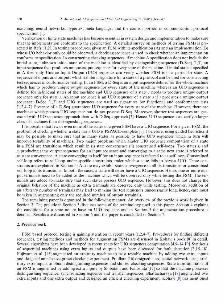
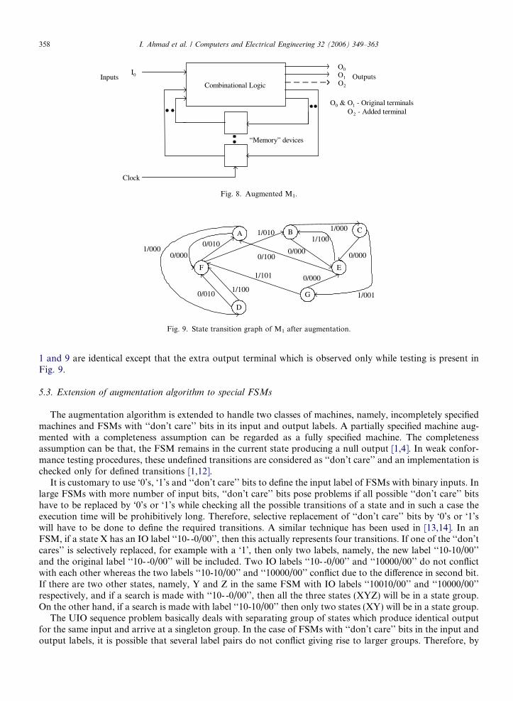
The augmentation of output labels of M1 is shown in Fig. 7 and the augmented M1 is shown in Fig. 8. InFig. 8, I0 is the input terminal, O0 to O2 are the output terminals and the extra terminal O2 is used only whiletesting. The state transition graph of the augmented machine is shown in Fig. 9. The transitions of M1 in Figs.
[E, A, 0/10]
10 @ 0
SG2
00 @ 1 00 @ 00
SG4
AB, DC, 1/000
[ABC, DCG,1/00]
C, G, 1/001
ED, BF, 1/100
[EDG, BFF, 1/10]
10 @ 0 10 @ 1
G, F, 1/101
SG5
[ABCG, FEEE, 0/00]
00 @ 0
ABCG, FEEE, 00/000
SG6
E, A, 0/100
[F, B,1/01]
SG1
01 @ 0
F, B, 1/010
[FD, AF, 0/01]
SG3
01 @ 0
FD, AF, 0/010
Fig. 7. Augmented transitions.
Combinational Logic
I0
O0
O1
O2
“Memory” devices
Clock
Inputs Outputs
O0 & O1 - Original terminalsO2 - Added terminal
Fig. 8. Augmented M1.
D
F
A
0/100
0/000
0/010
E
CB
0/0000/0001/000
G0/0101/100
1/101
1/000
1/001
1/010
0/000
1/100
Fig. 9. State transition graph of M1 after augmentation.
358 I. Ahmad et al. / Computers and Electrical Engineering 32 (2006) 349–363
1 and 9 are identical except that the extra output terminal which is observed only while testing is present inFig. 9.
5.3. Extension of augmentation algorithm to special FSMs
The augmentation algorithm is extended to handle two classes of machines, namely, incompletely specifiedmachines and FSMs with ‘‘don’t care’’ bits in its input and output labels. A partially specified machine aug-mented with a completeness assumption can be regarded as a fully specified machine. The completenessassumption can be that, the FSM remains in the current state producing a null output [1,4]. In weak confor-mance testing procedures, these undefined transitions are considered as ‘‘don’t care’’ and an implementation ischecked only for defined transitions [1,12].
It is customary to use ‘0’s, ‘1’s and ‘‘don’t care’’ bits to define the input label of FSMs with binary inputs. Inlarge FSMs with more number of input bits, ‘‘don’t care’’ bits pose problems if all possible ‘‘don’t care’’ bitshave to be replaced by ‘0’s or ‘1’s while checking all the possible transitions of a state and in such a case theexecution time will be prohibitively long. Therefore, selective replacement of ‘‘don’t care’’ bits by ‘0’s or ‘1’swill have to be done to define the required transitions. A similar technique has been used in [13,14]. In anFSM, if a state X has an IO label ‘‘10- -0/00’’, then this actually represents four transitions. If one of the ‘‘don’tcares’’ is selectively replaced, for example with a ‘1’, then only two labels, namely, the new label ‘‘10-10/00’’and the original label ‘‘10- -0/00’’ will be included. Two IO labels ‘‘10- -0/00’’ and ‘‘10000/00’’ do not conflictwith each other whereas the two labels ‘‘10-10/00’’ and ‘‘10000/00’’ conflict due to the difference in second bit.If there are two other states, namely, Y and Z in the same FSM with IO labels ‘‘10010/00’’ and ‘‘10000/00’’respectively, and if a search is made with ‘‘10- -0/00’’, then all the three states (XYZ) will be in a state group.On the other hand, if a search is made with label ‘‘10-10/00’’ then only two states (XY) will be in a state group.
The UIO sequence problem basically deals with separating group of states which produce identical outputfor the same input and arrive at a singleton group. In the case of FSMs with ‘‘don’t care’’ bits in the input andoutput labels, it is possible that several label pairs do not conflict giving rise to larger groups. Therefore, by

I. Ahmad et al. / Computers and Electrical Engineering 32 (2006) 349–363 359
selectively replacing ‘‘don’t care’’ bits with ‘0’s and ‘1’s, the transitions can be defined better which in turnproduces smaller groups.
In our algorithm completeness assumption is used to handle Incompletely specified FSMs. The algorithmchecks the transitions of FSMs with binary inputs and selectively replaces ‘‘don’t care’’ bits with ‘0’s and ‘1’s incertain input labels of transitions, thereby generating transitions with more defined input labels. All the ori-ginal input labels are also retained. This necessitates some preprocessing of transitions. From the state tran-sition graph of FSM, the existing I/O pairs are extracted. By assigning ‘0’s or ‘1’s selectively in the ‘‘don’tcare’’ positions on existing labels, new labels are created and included in the original set of labels. The labelmodification procedure presented in [19] has been used to create smaller cardinality state groups.
6. Experimental results
The experiments were conducted with FSMs reported in literature [4,6], generated machine M2, MCNCFSM benchmarks [20] and cross product FSMs generated from the MCNC benchmark set using a cross prod-uct generator on a Pentium 4/1.7 GHz PC. If M1 = (I1,O1, e1,d1,b1) and M2 = (I2,O2, e2,d2,b2), then the crossproduct machine is M3 = (I3,O3, e3,d3,b3), which is capable of executing M1 and M2 in parallel such that,S3 = ((s1, s2) j s1 2 S1 and s2 2 S2), I3 = ((i1, i2) j i1 2 I1 and i2 2 I2) and O3 = ((o1,o2) j o1 2 O1 and o2 2 O2).All the FSMs were reduced using Stamina [21]. The modified state transition table produced by the proposedalgorithm was used as input to a UIO computation algorithm [19] to check the performance of the augmen-
Table 1aAugmentation of FSM0 [4]
FSM before augmentation FSM after augmentation
Input Present state Next state Output Input Present state Next state Output
FSM0 [4]0 A B 0 0 A B 011 A C 0 1 A C 000 B A 1 0 B A 101 B C 0 1 B C 000 C B 0 0 C B 001 C A 1 1 C A 10
State UIO before augmentation UIOs after augmentation
A – 0/01B 0/1 0/10C 1/1 0/00
Table 1bAugmentation of FSM1 [6]
FSM before augmentation FSM after augmentation
Input Present state Next state Output Input Present state Next state Output
FSM1 [6]0 A A 0 0 A A 001 A C 0 1 A C 000 B A 0 0 B A 011 B B 1 1 B B 100 C C 1 0 C C 101 C B 1 1 C B 10
State UIO before augmentation UIOs after augmentation
A 1/0 0/00B – 0/01C 0/1 0/10

Table 1cAugmentation of M2
FSM before augmentation FSM after augmentation
Input Present state Next state Output Input Present state Next state Output
M2
00 A A 0 00 A A 0010 A B 0 10 A B 0111 A C 0 11 A C 0000 B B 0 00 B B 0010 B A 1 10 B A 1011 B C 0 11 B C 0000 C C 0 00 C C 0010 C B 0 10 C B 0011 C B 0 11 C B 00
State UIO before augmentation UIOs after augmentation
A – 10/01B 10/1 10/10C 11/0 10/1 10/00
Table 2Performance measurements of MCNC benchmarks
FSM n ni no p a gpp b1 b2 b3 T (s) g
bbara 7 4 2 42 1 1 – – 1 0.03 1bbsse 13 7 7 208 1 1 1 – – 0.06 1beecount 4 3 4 20 2 1 2 – – 0.03 1cse 16 7 7 91 1 1 1 – – 0.08 1dk14 7 3 5 56 4 1 4 – – 0.05 1dk15 4 3 5 32 1 1 1 – – 0.03 1dk16 27 2 3 108 7 2 6 1 – 0.05 2dk17 8 2 3 32 1 1 1 – – 0.03 1dk27 7 1 2 14 3 2 2 1 – 0.00 2lion 4 2 1 11 1 1 1 – – 0.01 1lion9 4 2 1 16 1 1 1 – – 0.00 1opus 9 5 6 29 2 1 2 – – 0.03 1planet 48 7 19 115 1 1 1 – – 0.08 2s1 20 8 6 107 7 1 7 – – 0.08 2s27 5 4 1 30 1 1 1 – – 0.01 2s386 13 7 7 64 1 1 1 – – 0.03 2s820 24 18 19 230 3 2 – – 3 0.19 3s832 24 18 19 243 2 1 – – 2 0.16 3sse 13 7 7 208 1 1 1 – – 0.08 1styr 30 9 10 166 3 1 1 – 2 0.08 1
n No. of states.ni No. of inputs.p No. of transitions.no No. of outputs.
gpp No. of extra terminals with preprocessing.
g No. of extra terminals without preprocessing.a No. of states without UIO.b1 No. of states with one-hop convergence.b2 No. of states with detoured convergence.b3 No. of states with constrained self-loop.
.
360 I. Ahmad et al. / Computers and Electrical Engineering 32 (2006) 349–363

I. Ahmad et al. / Computers and Electrical Engineering 32 (2006) 349–363 361
tation algorithm. We report three performance parameters namely, number of states which did not have UIOs(a), number of extra terminals added with preprocessing (gpp) and without preprocessing (g), and computationtime (s) for all the FSMs. We also report the number of states with no UIOs identified by one-hop convergence(b1), detoured convergence (b2) and constrained self-loop (b3). The bs give us an indication of the relativeimportance of the conditions listed in our paper for identification of states with no UIO.
Tables 1a, 1b and 1c list the transitions of small FSMs and their UIOs computed before and after augmen-tation. Source of FSM0 and FSM1 are [4,6] and M2 was developed by the authors on the lines of MCNCbenchmark ‘‘bbara’’ [20]. First of all, we report the results for FSMs reported in literature [4,6] and M2 whichdo not have UIO. State A in FSM0 and state B in FSM1 do not have UIO due to one-hop convergence. In M2,state A does not have UIO due to constrained self-loop. Complete details of the FSMs before and after aug-mentation are presented in Tables 1a, 1b and Table 1c. Even though more than one UIO may exist for statesof a FSM, we have reported only the first UIO computed for the states. Augmentation generated UIOs for allthe states of the FSMs. It is possible that augmentation may result in generating shorter UIO sequences as isdemonstrated in the case of M2.
In Table 2, performance measurements of our algorithm is presented for MCNC benchmark FSMs. Out of20 benchmark FSMs listed, in all the cases the number of states for which UIO did not exist were correctlyidentified and with the addition of minimum number of output terminals the UIOs of all the states couldbe computed. It is obvious from the table, that in most of the FSMs, one-hop convergence was the major fac-tor for a state not to have an UIO. In the case of 3 FSMs, namely, bbara, s820 and s832 constrained self-loopwas the main factor. In s1 there were as many as seven states without UIO which could be solved with just one
Table 3Performance measurements for cross-product machines
FSM n ni no p a g b1 b2 T (s)
beecount*dk14 28 6 9 1120 22 2 22 – 0.42beecount*dk17 32 5 7 640 18 2 18 – 0.17beecount*dk27 28 4 6 280 12 3 18 1 0.09beecount*shiftreg 32 4 5 320 16 3 16 – 0.11dk14*dk17 56 5 8 1792 35 2 35 – 0.94dk14*dk27 49 4 7 784 37 3 34 3 0.30dk14*shiftreg 56 4 6 896 32 3 32 – 0.30dk15*beecount 16 6 9 640 10 2 10 – 0.20dk15*dk14 28 6 10 1792 19 2 19 – 0.94dk15*dk17 32 5 8 1024 11 2 11 – 0.39dk15*lion 16 5 6 352 7 2 7 – 0.19dk15*shiftreg 32 4 6 512 8 3 8 – 0.13dk15*train4 16 5 6 448 7 2 7 – 0.19dk17*bbara 56 6 5 1344 14 3 7 – 0.45dk17*shiftreg 64 3 4 512 8 3 8 – 0.19dk27*ex6 56 6 10 476 24 2 16 8 0.20lion*beecount 16 5 5 300 10 2 10 – 0.08lion*dk14 28 5 6 616 19 2 19 – 0.27lion*dk17 32 4 4 352 11 2 11 – 0.14lion*ex6 32 7 9 374 8 1 8 – 0.19lion*shiftreg 32 3 2 176 8 3 8 – 0.06mc*beecount 16 6 9 640 8 1 8 – 0.23mc*dk14 28 6 10 560 16 1 16 – 0.23mc*dk27 28 4 7 140 12 2 8 4 0.05tav*beecount 16 7 8 1280 8 3 8 – 0.41train4*bbara 28 6 3 588 10 3 7 – 0.17train4*beecount 16 5 5 280 10 2 10 – 0.09train4*dk14 28 5 6 784 19 2 19 – 0.28train4*dk17 32 4 4 448 11 2 11 – 0.14train4*dk27 28 3 3 196 16 3 13 3 0.06train4*ex6 32 7 9 476 8 1 8 – 0.19train4*shiftreg 32 3 2 224 8 3 8 – 0.06

362 I. Ahmad et al. / Computers and Electrical Engineering 32 (2006) 349–363
extra terminal making it the best solution possible. This could be achieved due to the possibility of the stateswithout UIO being in different state groups with different output labels. Hence, a relationship between theextra terminals added while testing and the number of states without UIO could not be established. Selectivereplacement of ‘‘don’t care’’ bits with ‘0’s and ‘1’s as a preprocessing in FSMs with ‘‘don’t care’’ bits on inputand output labels facilitated in separating the states as much as possible there by easing the search for stateswithout UIO. Omitting the preprocessing step increased the number of states without UIO which in turnresulted in increasing the number of extra terminals needed. The shaded cells in the last column of Table 2show such cases.
In Table 3, performance measurements of cross product machines are presented and only machines with atleast seven states without UIO are included. Main factor contributing to identification of states with no UIOwas one-hop convergence and none of the FSMs in Table 3 had constrained self-loops. Even in the case oflarge FSMs like dk15*dk14, the execution time was remarkably negligible. The extra terminals added whiletesting never exceeded 3. It can be seen that the number of extra terminals added in the case of dk14*dk17was as small as 2 for 35 states without UIO.
7. Conclusions
A heuristic algorithm for improving the state verification capability of an FSM is presented. Two necessaryconditions for states not to possess UIO are identified. The original behavior of the machine is maintained andone or more output terminals are added to the machine which will be used only while testing. The sequencesgenerated by the extra terminals make sure that the every state of the machine possesses UIO sequence. More-over, sorting of state groups before the addition of terminals aided in reducing the extra terminals and speededup the augmentation process. The label redefinition technique used as a preprocessing step in special machinesto selectively define the input labels of FSM made the search for states without UIO easier in these FSMs.Even though the problem of checking whether a state has a UIO in a given FSM is PSPACE-complete, wecould identify states with no UIO and augment large number of FSMs including MCNC benchmarks. Furtherresearch study is needed to establish the relationship between the extra output terminals to be added and thenumber of states with no UIO sequence.
Acknowledgement
This research is funded by Kuwait University Grant EO 07/01.
References
[1] Lee D, Yannakakis M. Principles and methods of testing finite state machines – a survey. Proc IEEE 1996;84(8):1089–123.[2] Sidhu DP, Leung T. Formal methods for protocol testing: A detailed study. IEEE Transactions on Software Engineering
1989;15(4):413–26.[3] Hierons RM, Ural H. Reduced length checking sequences. IEEE Trans Comput 2002;51(9):1111–7.[4] Sabnani KK, Dahbura AT. A protocol test generation procedure. Comput Networks ISDN Syst 1988;15(4):285–97.[5] Shen YN, Lombardi F, Dahbura AT. Protocol conformance testing using multiple UIO sequences. IEEE Trans Commun
1992;40(8):1282–7.[6] Lee D, Yannakakis M. Testing finite-state machines: state identification and verification. IEEE Trans Comput 1994;43(3):306–20.[7] Kim C, Song JS. Test sequence generation methods for protocol conformance testing. In: Proceedings of the eighth annual
international computer software and applications conference, Taipei, Taiwan, 9–11 November 1994, p. 169–74.[8] Kohavi Z. Switching and finite automata theory. New York: Mc-Graw Hill Company; 1978.[9] Schin D, Shen YN, Lombardi F. An approach for UIO generation for FSM verification and validation. In: Proceedings of the IEEE
international symposium on circuits and systems, London, UK, 30 May–2 June 1994, p. 303–6.[10] Naik K. Efficient computation of unique input/output sequences in finite-state machines. IEEE/ACM Trans Networking
1997;5(4):585–99.[11] Chen W. Obtaining unique input/output sequences of communication protocol. IEICE Trans Commun 1997;E80-B(10):1509–13.[12] Sun X, Shen Y, Feng C, Lombardi F. Protocol conformance testing using unique input/output sequences. Singapore: World
Scientific Publishing Co.; 1997.

I. Ahmad et al. / Computers and Electrical Engineering 32 (2006) 349–363 363
[13] Dechang S, Babiraju V, Waali J. Fast state verification. In: proceedings of the ACM / IEEE thirty-fifth design automation conference,San Francisco, CA, 15–19 June 1998, p. 619–24.
[14] Sun H, Gao M, Liang A. Study on UIO sequence generation for sequential machine’s functional test. In: Proceedings of the fourthinternational conference on ASIC, Shangai, China, 22–25 October 2001, p. 628–32.
[15] Fujiwara H, Nagao Y, Sasao T, Kinoshita K. Easily testable sequential machines with extra inputs. IEEE Trans Comput 1975;C-24(8):821–6.
[16] Pradhan DK. Sequential network using extra inputs for fault detection. IEEE Trans Comput 1983;C-32(3):319–23.[17] Shibatani S, Kinoshita K. Synthesis of easily testable sequential circuits with checking sequences. In: Proceedings of first Asian test
symposium, Hiroshima, Japan, 26–27 November 1992, p. 200–3.[18] Bhattacharya A. On a novel approach of fault detection in an easily testable sequential machine with extra inputs and extra outputs.
IEEE Trans Comput 1983;C-32(3):323–5.[19] Ahmad I, Ali FM, Das AS. LANG – Algorithm for constructing unique input/output sequences in finite state machines. IEE Proc
Comput Digital Tech 2004;151(2):131–40.[20] Yang. Logic synthesis and optimization benchmarks user guide, Version 3.0, MCNC, 1991.[21] Hachtel GD, Rho JK, Somenzi F, Jacoby RM. Exact and heuristic algorithms for minimization of incompletely specified state
machines. IEEE Trans Comput-Aided Design 1994;13(2):167–77.