Synthesis of cybernetic structure of optimal spooler · The cybernetic structure of optimum spooler...
5
297 Metallurgical and Mining Industry No. 9 — 2015 Automatization Introduction. For achievement of the global control objective, it is necessary to create such controlled systems, within which the functions of obtaining of the required qual- ity of technological product and necessary quantity of finished product are carried out by different special- ized systems. The controlled systems of such class only can be optimum, as they have necessary degrees of freedom. If within the controlled system, one system solves problems of quality and quantity at the same time, its processes cannot be optimized. The controlled systems constructed with the use of such “universal” systems can be defined by the concept “rigidly bound systems”. Synthesis of cybernetic structure of optimal spooler Igor Lutsenko D.Sc. in engineering, associate professor, professor Chair of electronic equipment Kremenchuk Mykhailo Ostohradskyi National University Ukraine, Kremenchuk E-mail: [email protected] Fomovskaya Elena PhD in Technical Sciences, associate professor Head of Chair of electronic equipment Kremenchuk Mykhailo Ostohradskyi National University Ukraine, Kremenchuk E-mail: [email protected] Abstract The cybernetic structure of optimum spooler was synthesized. It is established that systems of this class consist of two independent control subsystems. Interfaces standards of subsystems of control, optimization and technological subsystem were developed. Use of subsystems standard modules provides possibility of on-line diagnostics of faults, automation of defective subsystem search, its disabling and activating of standby subsystem. The optimization subsystem is focused on criterion of resources use efficiency. Key words: SPOOLER, STOCK CONTROL SYSTEM, OPTIMUM SYSTEM, CONTROL SUBSYSTEM, OP- TIMIZATION SUBSYSTEM
Transcript of Synthesis of cybernetic structure of optimal spooler · The cybernetic structure of optimum spooler...

297Metallurgical and Mining IndustryNo. 9 — 2015
Automatization
Introduction. For achievement of the global control objective, it
is necessary to create such controlled systems, within which the functions of obtaining of the required qual-ity of technological product and necessary quantity of finished product are carried out by different special-ized systems. The controlled systems of such class
only can be optimum, as they have necessary degrees of freedom.
If within the controlled system, one system solves problems of quality and quantity at the same time, its processes cannot be optimized. The controlled systems constructed with the use of such “universal” systems can be defined by the concept “rigidly bound systems”.
Synthesis of cybernetic structure of optimal spooler
Igor Lutsenko
D.Sc. in engineering, associate professor, professorChair of electronic equipment
Kremenchuk Mykhailo Ostohradskyi National UniversityUkraine, KremenchukE-mail: [email protected]
Fomovskaya Elena
PhD in Technical Sciences, associate professorHead of Chair of electronic equipment
Kremenchuk Mykhailo Ostohradskyi National UniversityUkraine, Kremenchuk
E-mail: [email protected]
AbstractThe cybernetic structure of optimum spooler was synthesized. It is established that systems of this class consist of two independent control subsystems. Interfaces standards of subsystems of control, optimization and technological subsystem were developed.Use of subsystems standard modules provides possibility of on-line diagnostics of faults, automation of defective subsystem search, its disabling and activating of standby subsystem. The optimization subsystem is focused on criterion of resources use efficiency.Key words: SPOOLER, STOCK CONTROL SYSTEM, OPTIMUM SYSTEM, CONTROL SUBSYSTEM, OP-TIMIZATION SUBSYSTEM
Metallurgical and Mining Industry298 No. 9 — 2015
AutomatizationFor example, if the consumption system needs to
obtain more crushed ore per unit time within such rigidly bound systems, the previous system must in-crease the productivity in an appropriate manner even if “it is not profitably”.
In optimum systems between consumption system and system of specified quality maintenance, there is a system, which is usually positioned either as stock control system or as spooler of a technological prod-uct in literature. If it is necessary to deliver the re-quired volume of production to the consumer, there is no need to increase productivity of conversion system as the necessary stocks were formed in spooler.
As a rule, the processes optimization of such sys-tem is implemented with use of technology mini-mum-maximum.
Distinctive feature of spooler with use of technol-ogy minimum–maximum is necessity of continuous control of stock level with use of elements of auto-matic equipment. On the other hand, it is convenient to solve the implementation of optimum control prin-ciples with use of computer machines. In this regard, development of standards of the hardware, software and their interaction requires constructing of single architecture of cybernetic part of divisionary system.
At the present time, we did not get a chance to find out the works, where the design and interaction of internal mechanisms of spoolers, such as spooler minimum-maximum, are discovered.
In this regard, the development problem of the internal structure standards of spooler and interfaces of its internal objects is an important scientific and practical task.
The objective of this work is synthesis of cyber-netic customization of spoolers of technological prod-ucts with use of technology minimum-maximum.
Synthesis of the integrated structure of spooler in the form of subsystems provides an opportunity for independent research and improvement of subsystem of control or optimization. The system survivability, operational efficiency of fault diagnostics, possibil-ity of search automation of defective subsystem, its disabling and standby subsystem activation are in-creased; the possibility of functional and interface standardization at the subsystems level is provided.
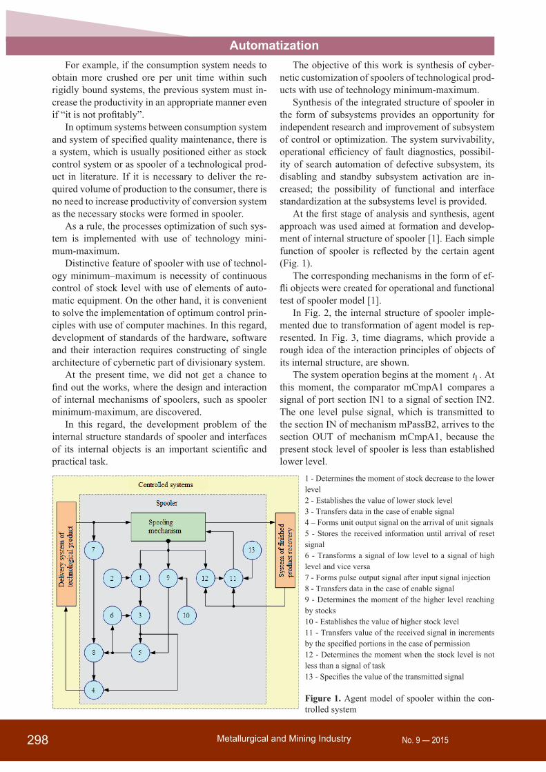
At the first stage of analysis and synthesis, agent approach was used aimed at formation and develop-ment of internal structure of spooler [1]. Each simple function of spooler is reflected by the certain agent (Fig. 1).
The corresponding mechanisms in the form of ef-fli objects were created for operational and functional test of spooler model [1].
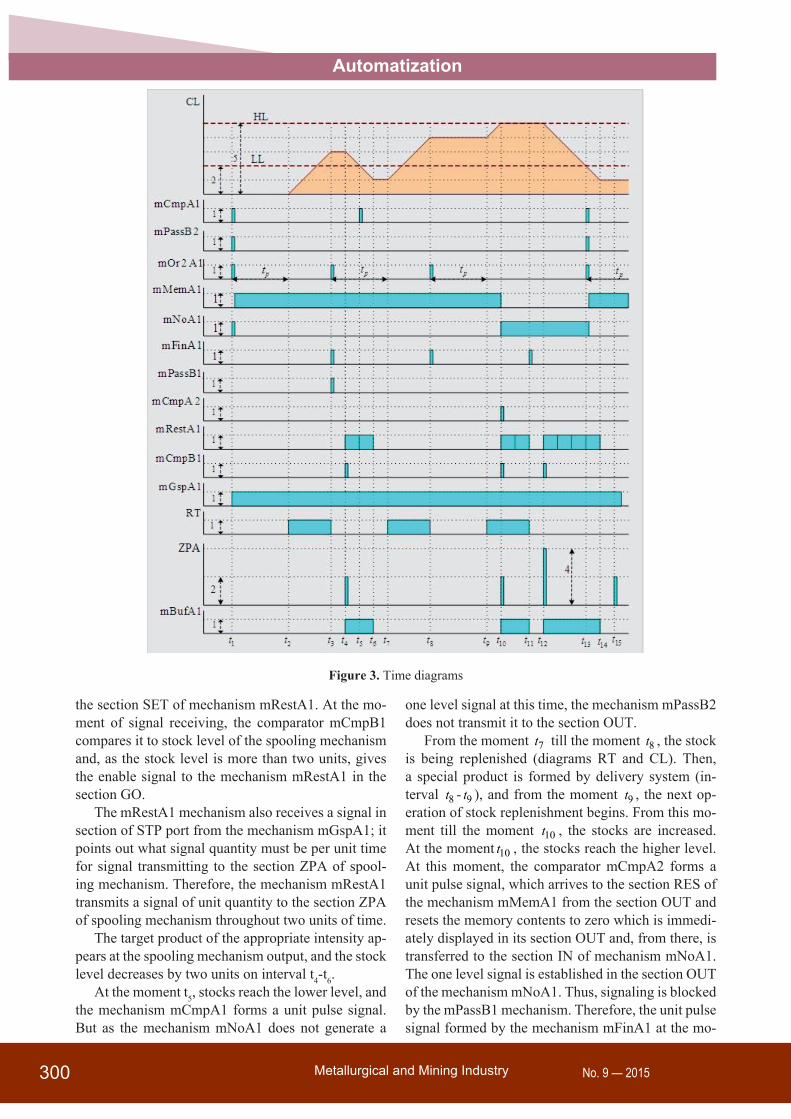
In Fig. 2, the internal structure of spooler imple-mented due to transformation of agent model is rep-resented. In Fig. 3, time diagrams, which provide a rough idea of the interaction principles of objects of its internal structure, are shown.
The system operation begins at the moment 1t . At this moment, the comparator mCmpA1 compares a signal of port section IN1 to a signal of section IN2. The one level pulse signal, which is transmitted to the section IN of mechanism mPassB2, arrives to the section OUT of mechanism mCmpA1, because the present stock level of spooler is less than established lower level.
1 - Determines the moment of stock decrease to the lower level2 - Establishes the value of lower stock level3 - Transfers data in the case of enable signal4 – Forms unit output signal on the arrival of unit signals5 - Stores the received information until arrival of reset signal6 - Transforms a signal of low level to a signal of high level and vice versa7 - Forms pulse output signal after input signal injection8 - Transfers data in the case of enable signal9 - Determines the moment of the higher level reaching by stocks10 - Establishes the value of higher stock level11 - Transfers value of the received signal in increments by the specified portions in the case of permission12 - Determines the moment when the stock level is not less than a signal of task13 - Specifies the value of the transmitted signal
Figure 1. Agent model of spooler within the con-trolled system

299Metallurgical and Mining IndustryNo. 9 — 2015
Automatization
Figure 2. The interface model of spooler implementing the technology minimum-maximum
As the mechanism mPassB2 did not form an out-put signal, there is a signal of zero level in the section OUT of the mechanism mMemA1. Therefore, in the section OUT of the mechanism mNoA1, there is a shaped signal of one level which continuously passes to the section CRD of mechanism mPassB2. This unit enable signal provides displacement of signal of the section IN to the section OUT of mechanism mPassB2. From here, the pulse signal passes to the section IN of mechanism mMemA1 and the section IN2 of mechanism mOr2A1.Thus, the signal of one level is established in the section OUT of mechanism mMemA1, and the unit pulse signal arrives to sys-tem of special product delivery from the section OUT of mechanism mOr2A1. The signal of zero level is established in the section OUT of the mechanism mNoA1.
Process of necessary product formation takes cer-tain time pt from delivery system. After this period,
the special product begins arriving to the section RT of spooling mechanism at the moment 2t (diagram RT, interval 2t - 3t ), and stock level is increased on the interval 2t - 3t (diagram CL).
At the moment 3t , process of special prod-uct delivery to an input of the spooling mechanism stops, and the mechanism mFinA1 forms a unit sig-nal, which passes to the section IN of mechanism mPassBm1 from the section OUT. As the one level signal arrives to the section CRD of mPassB1 from the section OUT of mechanism mMemA1, the sig-nal from the section IN arrives to the section OUT of mPassB1, and from there, through the section IN1 of the mechanism mOr2A1 into its section OUT and further to system of special product delivery.
At the moment 4t , the signal from system of re-ceiving of 2 units of target product arrives into the section ZPA of system sSepA. This signal arrives to the section In1 of the mechanism mCmpB1 and to
Metallurgical and Mining Industry300 No. 9 — 2015
Automatization
Figure 3. Time diagrams
the section SET of mechanism mRestA1. At the mo-ment of signal receiving, the comparator mCmpB1 compares it to stock level of the spooling mechanism and, as the stock level is more than two units, gives the enable signal to the mechanism mRestA1 in the section GO.
The mRestA1 mechanism also receives a signal in section of STP port from the mechanism mGspA1; it points out what signal quantity must be per unit time for signal transmitting to the section ZPA of spool-ing mechanism. Therefore, the mechanism mRestA1 transmits a signal of unit quantity to the section ZPA of spooling mechanism throughout two units of time.
The target product of the appropriate intensity ap-pears at the spooling mechanism output, and the stock level decreases by two units on interval t4-t6.
At the moment t5, stocks reach the lower level, and the mechanism mCmpA1 forms a unit pulse signal. But as the mechanism mNoA1 does not generate a
one level signal at this time, the mechanism mPassB2 does not transmit it to the section OUT.
From the moment 7t till the moment 8t , the stock is being replenished (diagrams RT and CL). Then, a special product is formed by delivery system (in-terval 8t - 9t ), and from the moment 9t , the next op-eration of stock replenishment begins. From this mo-ment till the moment 10t , the stocks are increased. At the moment 10t , the stocks reach the higher level. At this moment, the comparator mCmpA2 forms a unit pulse signal, which arrives to the section RES of the mechanism mMemA1 from the section OUT and resets the memory contents to zero which is immedi-ately displayed in its section OUT and, from there, is transferred to the section IN of mechanism mNoA1. The one level signal is established in the section OUT of the mechanism mNoA1. Thus, signaling is blocked by the mPassB1 mechanism. Therefore, the unit pulse signal formed by the mechanism mFinA1 at the mo-
301Metallurgical and Mining IndustryNo. 9 — 2015
Automatizationment of completion of a special product delivery op-eration (moment 11t ) does not pass to the section In1 of the mechanism mOr2A1. But, the base for starting of stock replenishment process, when reaching of the lower level from the mCmpA1 mechanism, is pre-pared.
At the moment 10t , the signal of replenishment by two units arrives in the section ZPA of sSepA. As the intensity of delivery and recovery of special and tar-get products coincides, the stock level is not changed on an interval 10t - 11t .
At the moment 12t , the signal of task for delivery of a target product arrives to the section ZPA of sys-tem sSepA. As the stock level is higher than a task signal, the target product is given to receiving system. However, at the moment 13t , the signal of task ar-rives again. But, as the stock level is less than a task signal quantity, the comparator mCmpB1 does not provide an enable signal for control to the mechanism mRestA1.
At the same time, at the moment of decrease in stocks to the lower level (moment 14t ), the control is formed from the mCmpA1 mechanism using the foregoing technology.
After synthesis of basic structure of separation system, we can pass to determination of structure of its subsystems.
The researches of the obtained structure show that the spooler consists of two independent control sub-systems. That is, unlike the products transformation systems, where the signal of task predetermines con-trol signal injection, there is no such principle in the spooler. Besides that, the necessity of independent installation of two levels points out that the subsys-tem forming a control signal must receive values of
the lower and higher levels from two corresponding optimization subsystems according to criterion of re-sources use efficiency [2].
ConclusionThe researches of internal structure of spooler al-
lowed us to discover the unidentified feature; that is existence of two independent control subsystems in spooler internal structure.
The subsystem of formation of an external signal of task defines the moment of the starting of stock replenishment considering the established levels of minimum- maximum. Thus, the values of these lev-els are determined by the corresponding optimization subsystems.
The obtained interface model is cybernetic as its structure does not depend on a spooling product.
The obtained model can be used for development of standard interfaces of control subsystems of spool-ers implementing the technology minimum–maxi-mum.
References1. Lutsenko I. (2014) Systems engineering of op-
timal control I. Synthesis of the structure of the technological product conversion system (part1) . Eastern-European Journal of Enter-prise Technologies. Vol. 6, No2(72), p.p. 28-37. DOI: 10.15587/1729-4061.2014.28724
2. Lutsenko I. (2015) Identification of target system operations. Development of global ef-ficiency criterion of target operations. East-ern-European Journal of Enterprise Tech-nologies. Vol. 2, No2(74), p.p. 35–40. DOI: 10.15587/1729-4061.2015.38963


![[Dip16] Cybernetic Insurgence III: Re ... Extended... · Cybernetic Insurgence III: Re-Generative Advances ... urban morphology, ... Cybernetic Insurgence III; Re-Generative Advances](https://static.fdocuments.in/doc/165x107/5ae3ab2e7f8b9a5b348db8c9/dip16-cybernetic-insurgence-iii-re-extended-cybernetic-insurgence-iii.jpg)