SYNTHESIS OF COMPLIANT BISTABLE FOUR-LINK MECHANISMS...
85
SYNTHESIS OF COMPLIANT BISTABLE FOUR-LINK MECHANISMS FOR TWO POSITIONS A THESIS SUBMITTED TO THE GRADUATE SCHOOL OF NATURAL AND APPLIED SCIENCES OF MIDDLE EAST TECHNICAL UNIVERSITY BY LEVENT SUBAŞI IN PARTIAL FULFILLMENT OF THE REQUIREMENTS FOR THE DEGREE OF MASTER OF SCIENCE IN MECHANICAL ENGINEERING NOVEMBER 2005
Transcript of SYNTHESIS OF COMPLIANT BISTABLE FOUR-LINK MECHANISMS...
SYNTHESIS OF COMPLIANT BISTABLE FOUR-LINK MECHANISMS FOR
TWO POSITIONS
A THESIS SUBMITTED TO
THE GRADUATE SCHOOL OF NATURAL AND APPLIED SCIENCES
OF
MIDDLE EAST TECHNICAL UNIVERSITY
BY
LEVENT SUBAŞI
IN PARTIAL FULFILLMENT OF THE REQUIREMENTS
FOR
THE DEGREE OF MASTER OF SCIENCE
IN
MECHANICAL ENGINEERING
NOVEMBER 2005

Approval of the Graduate School of Natural and Applied Sciences
Prof. Dr. Canan ÖZGEN
I certify that this thesis satisfies all the requirements as a thesis for the degree of
Master of Science
Prof. Dr. Kemal İDER
Head of Department
This is to certify that we have read this thesis and that in our opinion it is fully
adequate, in scope and quality, as a thesis for the degree of Master of Science
Prof. Dr. Eres SÖYLEMEZ
Supervisor
Examining Committee Members
Prof. Dr. Kemal İDER (METU, ME)
Prof. Dr. Eres SÖYLEMEZ (METU, ME)
Prof. Dr. Kemal ÖZGÖREN (METU, ME)
Asst. Prof. Ergin TÖNÜK (METU, ME)
Prof. Dr. Yavuz YAMAN (METU, AEE)

iii
I hereby declare that all information in this document has been obtained and
presented in accordance with academic rules and ethical conduct. I also
declare that, as required by these rules and conduct, I have fully cited and
referenced all material and results that are not original to this work.
Name, Last Name: Levent SUBAŞI
Signature :
iv
ABSTRACT
SYNTHESIS OF COMPLIANT BISTABLE FOUR-LINK MECHANISMS FOR
TWO POSITIONS
Subaşı, Levent
M.S, Department of Mechanical Engineering
Supervisor: Prof.Dr. Eres SÖYLEMEZ
November 2005, 77 pages
The aim of this study is to present a design approach for compliant bistable four-
link mechanisms. The design constraints are the two positions of the mechanism,
the force required to snap between the positions and the fatigue life of the
designed mechanism. The theory presented here will be applied to the door lock
mechanism used in commercial dishwashers, which is originally designed as a
rigid inverted slider crank mechanism snapping between two positions with the
force applied by a spring. The mechanism is re-designed as a compliant bistable
four-link mechanism and a prototype has been manufactured.
Keywords: Compliant mechanism, Bistable mechanism, Four-bar mechanism,
Pseudo-rigid-body model.
v
ÖZ
ÇİFT POZİSYONLU ESNEK DÖRT UZUVLU MEKANİZMALARIN İKİ
POZİSYONA GÖRE SENTEZİ
Subaşı, Levent
Yüksek Lisans, Makina Mühendisliği Bölümü
Tez Yöneticisi: Prof.Dr. Eres SÖYLEMEZ
Kasım 2005, 77 sayfa
Bu çalışmanın amacı, çift pozisyonlu esnek dört uzuvlu mekanizmalar için bir
tasarım yaklaşımı sunmaktır. Tasarım girdileri, mekanizmanın iki pozisyonu,
pozisyonlar arasında geçiş için gereken kuvvet ve mekanizmanın ömrüdür.
Burada sunulan teori, bulaşık makinelerinde kullanılan kapı kilidi parçasına
uyarlanacaktır. Mevcut tasarımda bu mekanizma, yayla iki konuma sabitlenen,
rijit uzuvlardan oluşan bir kol-kızak mekanizmasıdır. Mekanizma çift pozisyonlu
esnek dört uzuvlu bir mekanizma olarak yeniden tasarlanmış ve prototip bir parça
üretilmiştir.
Anahtar kelimeler: Esnek mekanizma, Çift pozisyonlu mekanizma, Dört uzuvlu
mekanizma, Katımsı cisim modeli.
vi
TABLE OF CONTENTS
PLAGIARISM........................................................................................................iii
ABSTRACT...........................................................................................................iv
ÖZ............................................................................................................................v
TABLE OF CONTENTS........................................................................................vi
CHAPTER
1. LITERATURE SURVEY..............................................................................1
1.1 Compliant Mechanisms.........................................................................1
1.1.1 Definition......................................................................................1
1.1.2 Historical Background..................................................................1
1.1.3 Advantages of Compliant Mechanisms........................................3
1.1.4 Challenges of Compliant Mechanisms.........................................4
1.2 Compliant Bistable Mechanisms...........................................................5
1.3 Compliant MEMS..................................................................................6
1.3.1 Definition and Fabrication............................................................6
1.3.2 History of Bistable MEMS...........................................................6
1.3.3 Advantages and Challenges of Compliance in MEMS.................7
1.3.4 Bistable MEMS.............................................................................7
1.4 Design Methods.....................................................................................8
1.4.1 Pseudo Rigid Body Model............................................................8
1.4.2 Topology Synthesis and Optimization........................................12
1.4.3 Type Synthesis............................................................................14
1.5 Design Software...................................................................................15
1.5.1 Msc Adams.................................................................................15
1.5.2 PennSyn......................................................................................15
1.5.3 TopOpt........................................................................................16
1.5.4 Optishape....................................................................................18
1.5.5 CSDL..........................................................................................19

vii
2. PRELIMINARY CONCEPTS.....................................................................20
2.1 Rigid Mechanism Theory....................................................................20
2.2 Grashof’s Criterion..............................................................................23
2.3 Stability................................................................................................25
2.4 Pseudo Rigid Body Model of Compliant Segment Types...................26
2.5 Static Failure........................................................................................29
2.6 Fatigue Life Estimation........................................................................29
3. DESIGN OF A COMPLIANT BISTABLE FOUR-BAR...........................32
3.1 Potential Energy Equation...................................................................32
3.2 Design Steps.........................................................................................36
3.3 Designing a Door Lock Mechanism....................................................37
3.3.1 Design for One Torsional Spring................................................38
3.3.1.1 Deciding on the Two Coupler Positions.........................38
3.3.1.2 Choosing Initial Position of the Input Link....................39
3.3.1.3 Selecting one of the Ground Joint Locations..................40
3.3.1.4 Changing the Position of Other Ground Joint Connection.....41
3.3.1.5 Predicting the Value of Torsional Spring Constant........47
3.3.1.6 Realizing the Mechanism................................................47
3.3.1.7 Static Failure and Fatigue Life Analysis.........................50
3.3.2 Design for Several Torsional Springs.........................................53
3.3.2.1 Deciding on the Two Coupler Positions.........................53
3.3.2.2 Choosing Initial Position of the Input Link....................54
3.3.2.3 Selecting one of the Ground Joint Locations..................55
3.3.2.4 Changing the Position of Other Ground Joint Connection.....55
3.3.2.5 Predicting the Value of Torsional Spring Constants.......60
4. DISCUSSION AND CONCLUSION.........................................................62
REFERENCES......................................................................................................66

viii
APPENDIX A: Iteration Routine in Mathcad for one K.......................................69
APPENDIX B: Iteration Routine in Mathcad for several K..................................72
APPENDIX C: Mechanical Properties of Some Polymers....................................76
APPENDIX D: Example of a Compliant Mechanism for Many Torsional Springs......77
1
CHAPTER 1
LITERATURE SURVEY
In this chapter, general definition and classification of compliant mechanisms is
presented. Previous work on design and analysis methods is discussed. Some
design software dedicated to compliant mechanisms are also presented.
1.1 Compliant Mechanisms
1.1.1 Definition
Compliant mechanisms are flexible link mechanisms, which gain some or all of
their motion through the deflection of flexible members [12]. These mechanisms
can be fully compliant or partially compliant. A fully compliant mechanism is one
that has no rigid body joints. A partially compliant mechanism is one that has
some compliant members and some non-compliant joints [16].
1.1.2 Historical Background
Mother Nature has used compliance since the beginnings of life in things such as
plants, bird wings and legs of small insects. Inventors, inspiring from nature, have
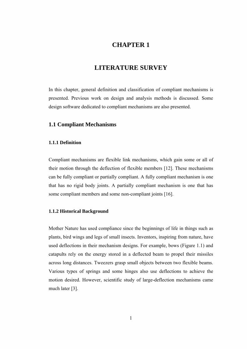
used deflections in their mechanism designs. For example, bows (Figure 1.1) and
catapults rely on the energy stored in a deflected beam to propel their missiles
across long distances. Tweezers grasp small objects between two flexible beams.
Various types of springs and some hinges also use deflections to achieve the
motion desired. However, scientific study of large-deflection mechanisms came
much later [3].

2
Figure 1.1: Historical longbow
Euler was the first to quantify the deflection of flexible beams with the
development of the Bernoulli-Euler equation in 1744. This equation, later, was
solved for large deflections of cantilever beams using elliptical integrals.
However, these solutions had very limited applications and were difficult to use.
Further research in this area performed has included finding large deflections of
beams with various geometries and developing methods of large-deflection finite
element analysis. Hill and Midha and Her also addressed the numerical analysis
of large-deflection beams [3],[16].
Semi-graphical methods are presented to be used for compliant mechanism
synthesis. Compliant mechanisms using compliant segments with both end forces
and end moments are investigated, along with three-dimensional compliant
mechanisms. Optimization to the design of compliant mechanisms is also
introduced. The effects of compliant members on mechanical advantage in a
mechanism have also been investigated later. A system of classification and
nomenclature for compliant mechanisms has also been established to aid in the
naming and analysis of compliant mechanisms in 1994 [3].
3
Howell and Midha introduced the idea of a pseudo-rigid-body model to simplify
compliant mechanism analysis [3]. In this model, a flexible mechanism link is
modeled as two or more rigid links joined by pin joints. A presentation of a
pseudo-rigid-body model for many types of flexible links was presented in the
following years. This model allows many compliant mechanisms to be designed
and analyzed much more easily than was previously possible.
In recent years, work has focused on methods of synthesizing new compliant
mechanisms. Ananthasuresh presented work done on applying topological
synthesis to the design of compliant mechanisms in 1994 [22]. In this method, a
computer-driven optimization routine attempts to find the right configuration of
flexible material to accomplish a certain task.
1.1.3 Advantages of Compliant Mechanisms
An advantage of compliant mechanisms is the reduction in the total number of
parts required to accomplish a certain task. This reduces manufacturing and
assembly time and cost [2]. Some mechanisms may even be constructed of one
piece. This kind of design has been given a new name recently, which is “Design
for no assembly” (DNA). Virtually, any product with multiple mechanical parts
performing a motion function can be considered for a no-assembly design
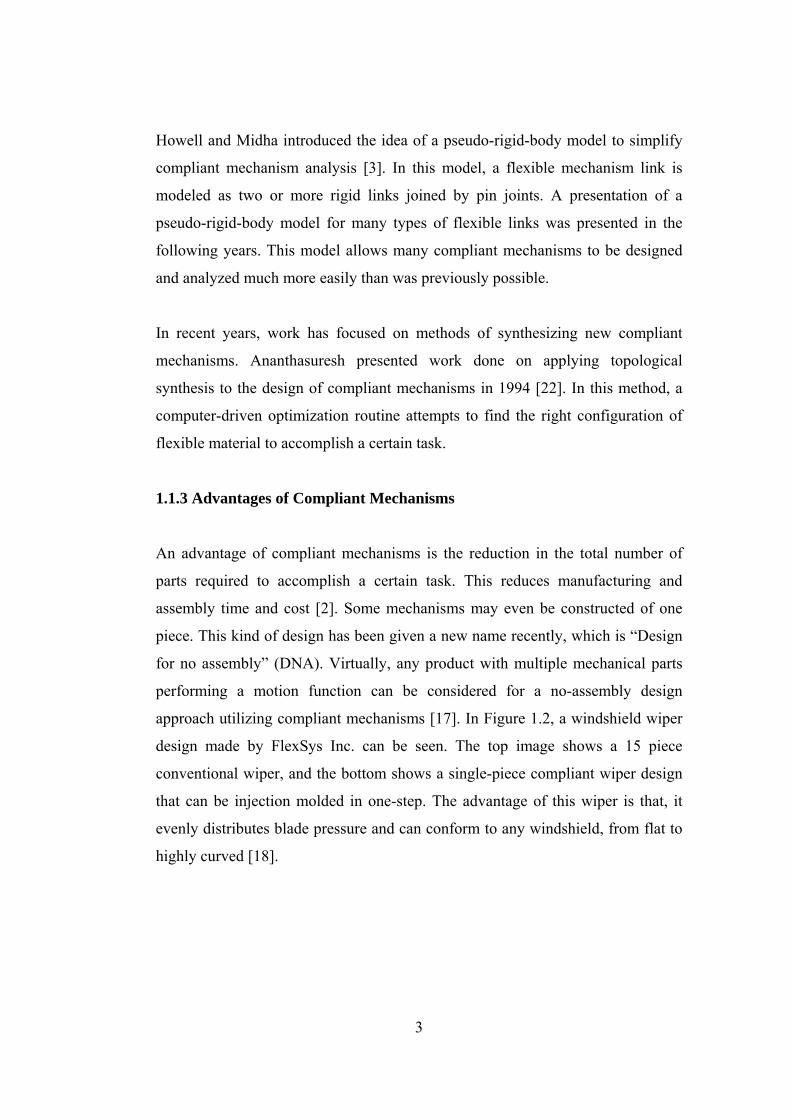
approach utilizing compliant mechanisms [17]. In Figure 1.2, a windshield wiper
design made by FlexSys Inc. can be seen. The top image shows a 15 piece
conventional wiper, and the bottom shows a single-piece compliant wiper design
that can be injection molded in one-step. The advantage of this wiper is that, it
evenly distributes blade pressure and can conform to any windshield, from flat to
highly curved [18].

4
Figure 1.2: Windshield wiper [18]
Since compliant mechanisms have fewer movable joints, need for lubrication is
less. Also because of that, mechanism precision is increased and vibration, noise
and backlash may also be reduced.
Because of the fact that compliant mechanisms are made up of flexible members,
the deflection of these members can be used as an advantage during design. For
example, constant force mechanisms can be designed.
Weight issue is generally significant in some applications, such as aerospace.
Compliant mechanisms are lighter than rigid link mechanisms synthesised for the
same purpose.
Another advantage of compliant mechanisms is the ease with which they are
miniaturized. Simple microstructures, actuators and sensors are widely used in
MEMS applications [2].
1.1.4 Challanges of Compliant Mechanisms
The main disadvantage of compliant mechanisms is the difficulty of analyzing
and designing them. Knowledge of mechanism analysis and synthesis methods
and the deflection of flexible members is required. It is necessary to understand
the interactions between “mechanism theory” and “strength of materials”, in a

5
complex situation. Some theory has been developed to simplify this problem. It is
important to learn these new advances to overcome the limitations.
Fatigue analysis is another issue. Since compliant segments are often loaded
cyclically, those members must be designed to have sufficient fatigue life to
perform their prescribed functions.
Energy storage of the flexible members can be a disadvantage for some
mechanisms. For example, if mechanism’s task is to transfer energy from input to
output, not all of input energy is transferred, but some is stored in the mechanism.
The motion from the deflection of compliant links is also limited by the strength
of the deflecting members. Furthermore, a compliant link cannot produce a
continuous rotational motion which is possible with a pin joint.
Compliant links that remain under stress for long periods of time or at high
temperatures may experience stress relaxation or creep [2].
1.2 Compliant Bistable Mechanisms
Bistable mechanical devices remain stable in two distinct positions without power
input. They find application in valves, switches, closures, and clasps. Figure 1.3 is
an example of a fully compliant bistable switch as fabricated (a) and closed (b).
Figure 1.3: Example of a compliant bistable switch [2]

6
Mechanically bistable behavior results from the storage and release of energy,
typically in springs, with stable positions occurring at local minima of stored
energy. Compliant mechanisms offer an elegant way to achieve this behavior by
incorporating both motion and energy storage into the same flexible element.
Compliance in bistable mechanisms offers several advantages, such as reduction
in part-count, reduced friction, and less backlash and wear. However, the design
of compliant bistable mechanisms is often not straight-forward or easy, requiring
the simultaneous analysis of both the motion and energy storage of the
mechanism.
Design methods found in literature, depend on the analysis of a previously
synthesised mechanism and finding two stable positions for that mechanism in
most cases. There is not a straightforward method presented for two position
synthesis or a method regarding force requirements.
1.3 Compliant MEMS
1.3.1 Definition and Fabrication
Micro-electro-mechanical systems (MEMS) integrate electrical circuitry with
mechanical devices having dimensions measured in microns [16]. Several
methods of MEMS fabrication exist. The most common one is surface
micromachining. Surface micromachining takes place on a silicon wafer using
techniques similar to those used for integrated circuit manufacturing [2].
1.3.2 History of Compliant MEMS
Although many researchers have used deflections to gain motion, some have
specifically studied the use of deflection in MEMS. Ananthasuresh applied
7
topological synthesis to the design of compliant MEMS [22]. He described the
principal benefits and challenges. Some examples of design of compliant MEMS
using the topological syntehsis method and pseudo-rigid-body models can be
found in literature [3].
1.3.3 Advantages and Challanges of Compliance in MEMS
The advantages of compliance in MEMS [2] are that, compliant mechanisms:
- Can be fabricated in a plane
- Require no assembly
- Require less space and are less complex
- Have less need for lubrication
- Have reduced friction and wear
- Have less clearance due to pin joints, resulting in higher precision
- Integrate energy storage elements (springs) with the other components
There are also some challanges associated with designing compliant MEMS. The
performance is highly dependent on the material properties, yet the design is
limited to a few materials that are compatible with the fabrication methods. Also,
the fabrication method itself creates some problems. For example, “stiction”
occurs in surface micromachining. The machined structure remains stuck to the
substrate and large force is necessary to move it [3].
1.3.4 Bistable MEMS
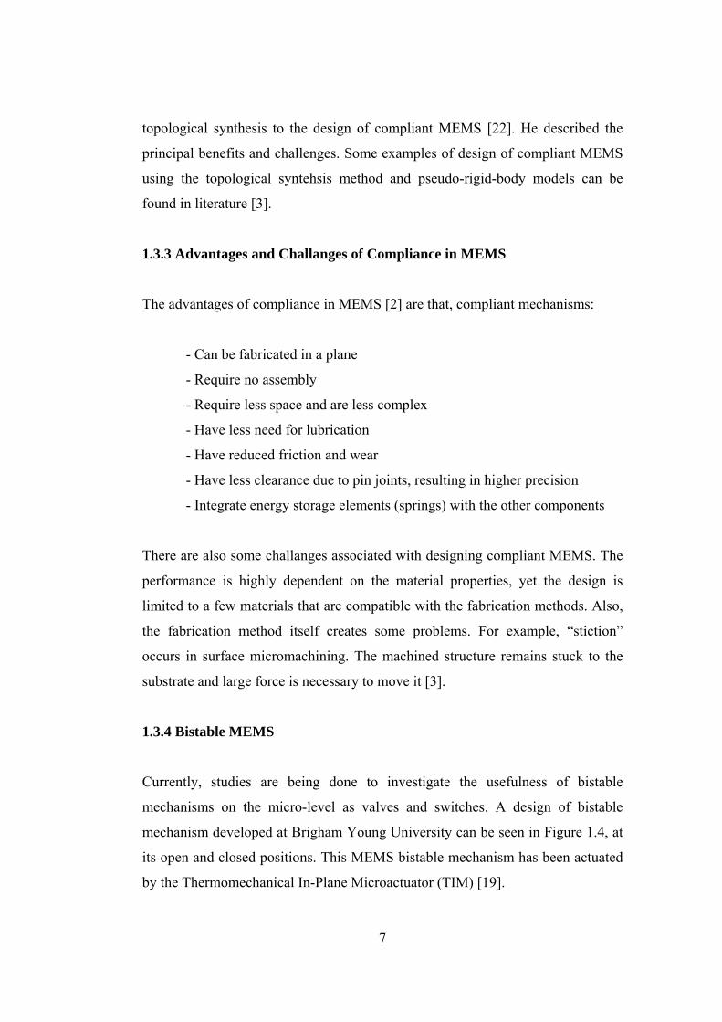
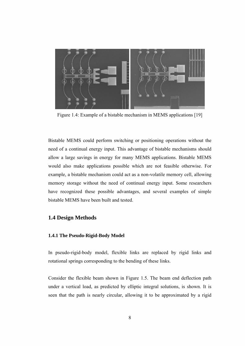
Currently, studies are being done to investigate the usefulness of bistable
mechanisms on the micro-level as valves and switches. A design of bistable
mechanism developed at Brigham Young University can be seen in Figure 1.4, at
its open and closed positions. This MEMS bistable mechanism has been actuated
by the Thermomechanical In-Plane Microactuator (TIM) [19].
8
Figure 1.4: Example of a bistable mechanism in MEMS applications [19]
Bistable MEMS could perform switching or positioning operations without the
need of a continual energy input. This advantage of bistable mechanisms should
allow a large savings in energy for many MEMS applications. Bistable MEMS
would also make applications possible which are not feasible otherwise. For
example, a bistable mechanism could act as a non-volatile memory cell, allowing
memory storage without the need of continual energy input. Some researchers
have recognized these possible advantages, and several examples of simple
bistable MEMS have been built and tested.
1.4 Design Methods
1.4.1 The Pseudo-Rigid-Body Model
In pseudo-rigid-body model, flexible links are replaced by rigid links and
rotational springs corresponding to the bending of these links.
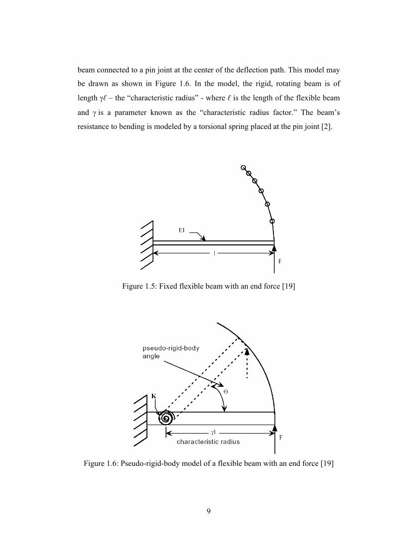
Consider the flexible beam shown in Figure 1.5. The beam end deflection path
under a vertical load, as predicted by elliptic integral solutions, is shown. It is
seen that the path is nearly circular, allowing it to be approximated by a rigid
9
beam connected to a pin joint at the center of the deflection path. This model may
be drawn as shown in Figure 1.6. In the model, the rigid, rotating beam is of
length γℓ – the “characteristic radius” - where ℓ is the length of the flexible beam
and γ is a parameter known as the “characteristic radius factor.” The beam’s
resistance to bending is modeled by a torsional spring placed at the pin joint [2].
Figure 1.5: Fixed flexible beam with an end force [19]
Figure 1.6: Pseudo-rigid-body model of a flexible beam with an end force [19]
10
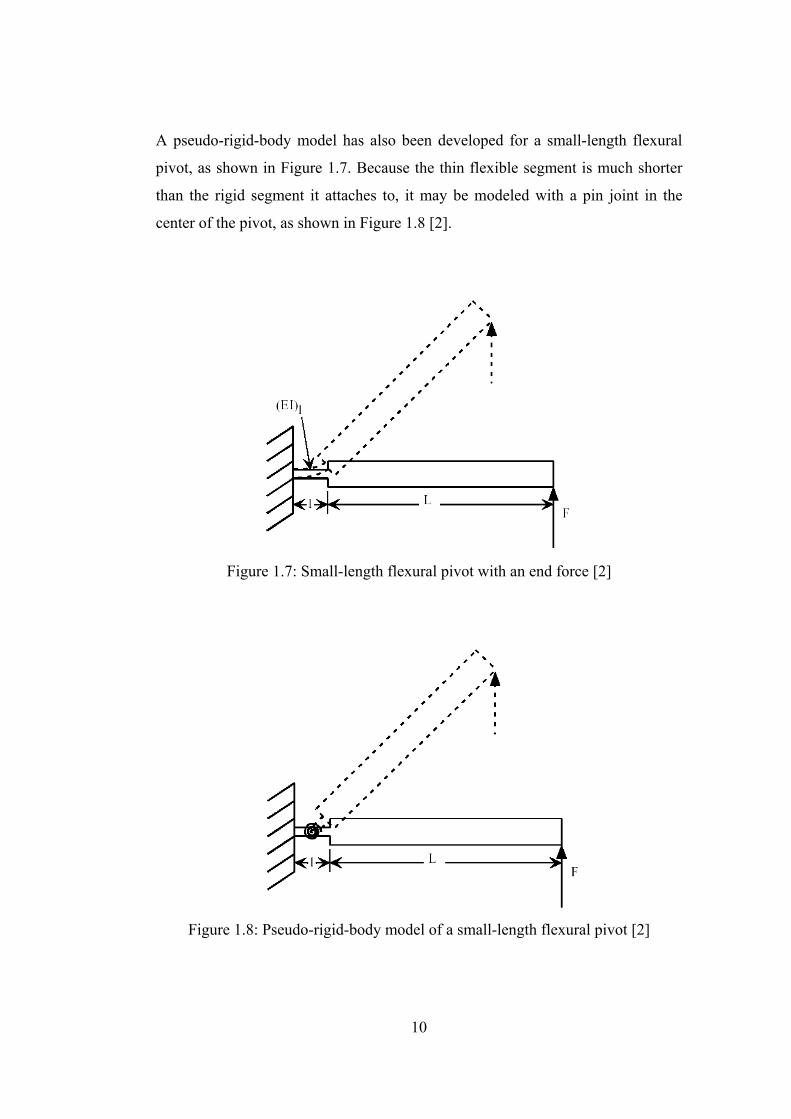
A pseudo-rigid-body model has also been developed for a small-length flexural
pivot, as shown in Figure 1.7. Because the thin flexible segment is much shorter
than the rigid segment it attaches to, it may be modeled with a pin joint in the
center of the pivot, as shown in Figure 1.8 [2].
Figure 1.7: Small-length flexural pivot with an end force [2]
Figure 1.8: Pseudo-rigid-body model of a small-length flexural pivot [2]

11
A living hinge is another case of small length flexural pivots. It is a very short,
very thin pivot. Because of its small stiffness compared to other segments usually
found in a compliant mechanism, it is often represented simply by a pin joint,
with no torsional spring.
The fixed-guided segment shown in Figure 1.9 also has a corresponding model.
This segment has a moving end which is constrained to remain parallel to its
original direction at every instant. The combination of force and moment at the
moving end create a moment distribution which is always zero at the center of the
beam. Hence, this segment may be modeled as two cantilever beams with forces
at the free ends. Placing the beams end to end results in a pseudo-rigid-body
model like that shown in Figure 1.10 [2].
Figure 1.9: Fixed-guided beam [2]
Figure 1.10: Pseudo-rigid-body model of a fixed-guided segment [2]
12
The pseudo-rigid-body model works very well in many situations, but it has
several limitations. It is very accurate over fairly large deflections, but it begins to
lose accuracy if the deflection angle becomes too high. Maximum deflection
angles are tabulated for keeping the deflection error under 0.5% [2]. Also, when
using this model, it must be kept in mind that the joint does not allow full rotation.
1.4.2 Topology Synthesis and Optimization
The goal of topology synthesis is to identify the optimum number and
connectivity of structural elements to achieve specified motion requirements.
Topology synthesis is a critical stage of the design process, due to the fact that the
main performance of a compliant system is determined by its structure
configuration.
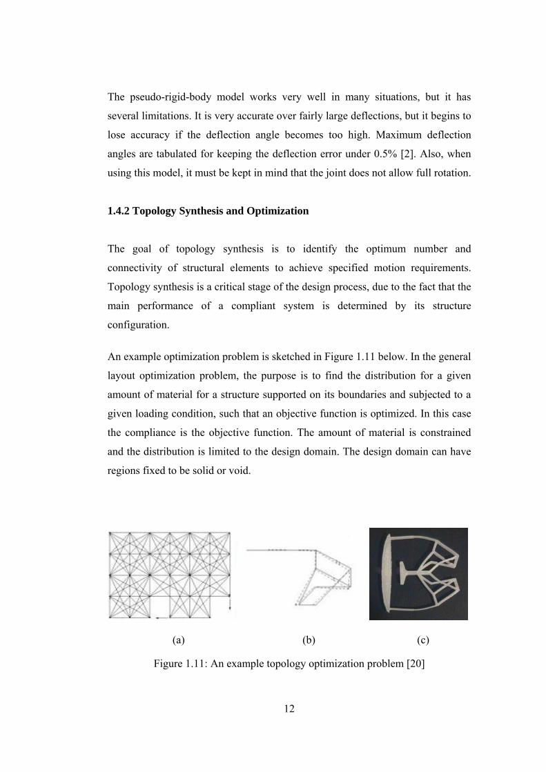
An example optimization problem is sketched in Figure 1.11 below. In the general
layout optimization problem, the purpose is to find the distribution for a given
amount of material for a structure supported on its boundaries and subjected to a
given loading condition, such that an objective function is optimized. In this case
the compliance is the objective function. The amount of material is constrained
and the distribution is limited to the design domain. The design domain can have
regions fixed to be solid or void.
(a) (b) (c)
Figure 1.11: An example topology optimization problem [20]

13
The topological synthesis of compliant mechanisms is accomplished through a
four-step process.
The first step is to enumerate the possible combinations of segment type (rigid or
compliant) without regard to the ground segment or the type of connections
between segments. After the possible segment combinations have been
enumerated, the design requirements are investigated and isomorphic chains are
removed from further consideration.
The second step of the topological synthesis process is to enumerate all the
possible combinations of connections between segments without regard to the
segment types being connected. Although, isomorphisms are not investigated
after this phase of the design process, resulting compliant chains are investigated
for conformance to requirements.
The third step of the topological synthesis process is to combine the results of the
segment and connection-type enumeration processes. The subsequent kinematic
chains are grouped by the original compliant chain from the segment enumeration
process. This grouping will help limit the extend of later isomorphism
investigations. The connections between segments are now examined to remove
any fixed connections between rigid segments and the chains are investigated to
remove any isomorphisms.
The fourth, and final, step of the topological synthesis process is to sequentially
fix, or ground, each rigid segment to form mechanisms. If more than one
mechanism is formed from a particular compliant chain, the mechanisms formed
from that chain need to be investigated to ensure that they are unique
(nonisomorphic).
As with all the steps of the topological synthesis process, the applicable design
requirements are enforced. The resulting mechanisms are forwarded for further
14
investigation, which may include a topological analysis or ranking to determine
which mechanisms will be selected for a particular application [20].
1.4.3 Type Synthesis
Type synthesis may be defined as the process of determining possible mechanism
structures to perform a given task or combination of tasks without regard to the
dimensions of the components. Type synthesis is performed to select a
mechanism type before carrying out dimensional synthesis, which is the process
of choosing mechanism dimensions to create a finished mechanism design.
The first step of the design process is the formulation of a mathematical model to
represent the structure of a mechanism. In rigid-body kinematics, graph theory
provides a mathematically rigorous representation of a mechanism structure
through the use of matrices. The matrix representation for compliant mechanisms
builds on the foundation established in rigid-body kinematics by adding
information regarding segment type and the connectivity between segments to the
matrices that represent a mechanism’s topology.
Bistable mechanisms require the use of compliant segments in such a way that the
mechanism has two stable states. Conventional type synthesis techniques make no
attempt to describe the energy states of the mechanism being designed. No
method currently exists which allows the description of the general stability of
mechanism topologies. The type synthesis technique consists of finding a number
of possible mechanism configurations, including kinematic inversions of each
type, which can solve the particular problem. The mechanism configuration which
will most easily solve the problem can then be chosen [3].

15
1.5 Design Software
1.5.1 MSC ADAMS/Autoflex
ADAMS/AutoFlex can be used for flexible body simulation of a mechanical
design. ADAMS/AutoFlex is useful for early simulation of the effects of
flexibility in mechanical systems when detailed finite element representations
aren’t available. Using ADAMS/AutoFlex, one can build a parametric flexible
body representation of a component, analyze the system, make changes to the
flexible body and evaluate the effect of the changes [21].
Figure 1.12: Snapshot of the MSC ADAMS/Autoflex Software [21]
1.5.2 PennSyn
PennSyn 1.0 is a software developed by the research group of Ananthasuresh, in
University of Pennsylvania [22]. It is implemented in Matlab 5.3 (release 11). It
has an easy-to-use menu with help buttons for each step. It generates compliant

16
topologies, animates the resulting motion, creates an IGES file of the solution,
and stores the solution for later use.
Figure 1.13: Snapshot of the PennSyn software [22]
1.5.3 TOPOPT
TOPOPT is a web-based topology optimization program developed by Dmitri
Tcherniak, Ole Sigmund, Thomas A. Poulsen and Thomas Buhl [20]. The
TOPOPT program solves the general topology optimization problem of
distributing a given amount of material in a design domain subject to load and
support conditions, such that the stiffness of the structure is maximized. The
restrictions on the TOPOPT program are the following:
17
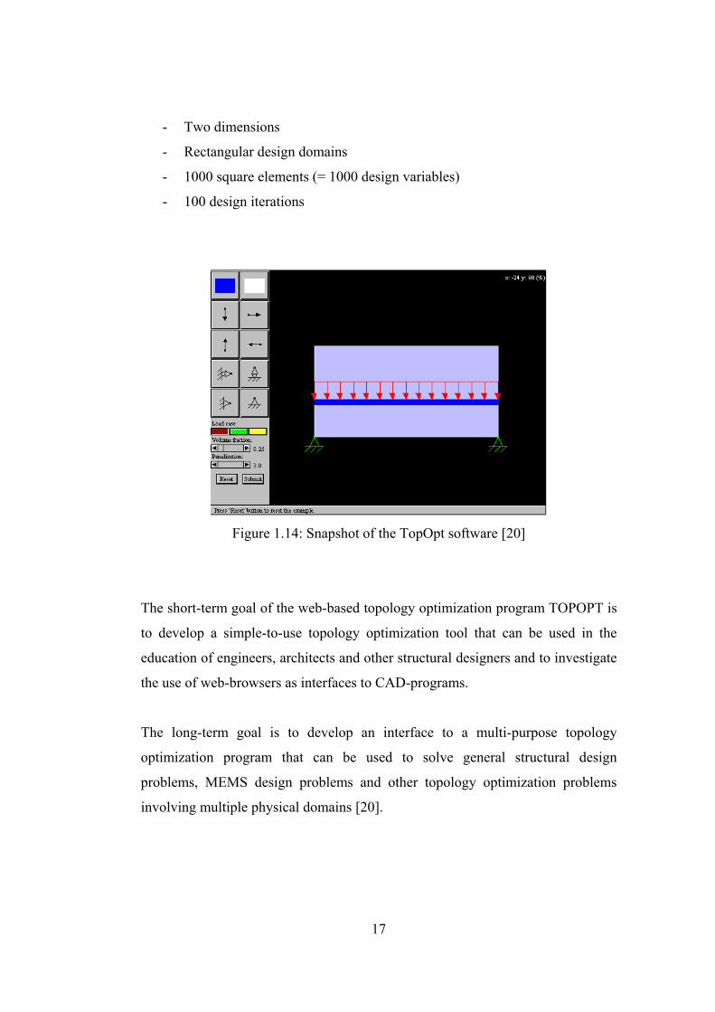
- Two dimensions
- Rectangular design domains
- 1000 square elements (= 1000 design variables)
- 100 design iterations
Figure 1.14: Snapshot of the TopOpt software [20]
The short-term goal of the web-based topology optimization program TOPOPT is
to develop a simple-to-use topology optimization tool that can be used in the
education of engineers, architects and other structural designers and to investigate
the use of web-browsers as interfaces to CAD-programs.
The long-term goal is to develop an interface to a multi-purpose topology
optimization program that can be used to solve general structural design
problems, MEMS design problems and other topology optimization problems
involving multiple physical domains [20].

18
1.5.4 OPTISHAPE
OPTISHAPE is a software developed by Quint Technologies [23]. It is based on
the structural topology optimization using the homogenization method. This
theory has been applied to the various kind of problems such as static problem,
eigenvalue problem and frequency response problem.
In the optimal design of the layout (topology) of elastic structures based on the
homogenization design theory, the design domain is assumed to be composed of
infinitely periodic microstructures, and each microstructure has a rectangular hole
as shown in Figure 1.15. The length of the sides and angle of rotation are design
variables, and the size of each element hole is determined by the sensitivity of the
objective function with the volume constraint and boundary conditions. Since
each element hole is allowed to possess a different size and angle of rotation,
uniformly distributed porous material in the initial stage will have a different size
of element holes at the end of optimization as shown in the figure. Therefore, if
the domain is viewed in a global sense, optimal topology is clearly seen [23].
Figure 1.15: Sketch to clarify the underlying concept of Optishape software [23]
19
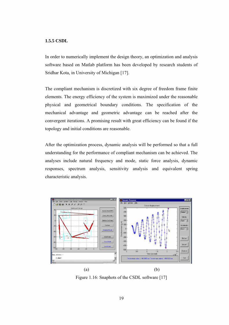
1.5.5 CSDL
In order to numerically implement the design theory, an optimization and analysis
software based on Matlab platform has been developed by research students of
Sridhar Kota, in University of Michigan [17].
The compliant mechanism is discretized with six degree of freedom frame finite
elements. The energy efficiency of the system is maximized under the reasonable
physical and geometrical boundary conditions. The specification of the
mechanical advantage and geometric advantage can be reached after the
convergent iterations. A promising result with great efficiency can be found if the
topology and initial conditions are reasonable.
After the optimization process, dynamic analysis will be performed so that a full
understanding for the performance of compliant mechanism can be achieved. The
analyses include natural frequency and mode, static force analysis, dynamic
responses, spectrum analysis, sensitivity analysis and equivalent spring
characteristic analysis.
(a) (b)
Figure 1.16: Snaphots of the CSDL software [17]
20
CHAPTER 2
PRELIMINARY CONCEPTS
Aim of this chapter is to introduce some basic concepts, including sections on
rigidity and compliance. Theory presented here will be used in the following
chapter to come up with a synthesis method of compliant four-bar mechanisms.
2.1 Rigid Mechanism Theory
Synthesis of a four-bar mechanism with two positions is introduced below.
Chasles’ theorem:
In Figure 2.1, a body representation is shown. Points A and B are any points
chosen on the body. Notation 1 and 2 represents the two positions of the body.
The plane motion of a rigid body most simply occurs by a rotation about the
“pole” which is located at the perpendicular biceptors of two pairs of homologous
points A1A2 and B1B2.
Accordingly, point A rotates with respect to a point chosen on the perpendicular
bicector of pair of homologous points A1A2. Also, point B rotates with respect to
a point chosen on the perpendicular bicector of pair of homologous points B1B2.
When the two points are chosen, a four-bar mechanism is constructed,
where│AB│becomes the coupler link.
A0A1B1B0 shows the first position of the four-bar, whereas A0A2B2B0 shows the
second position. While performing the synthesis, A0 and B0 can be selected in
infinitely many ways [15].
21
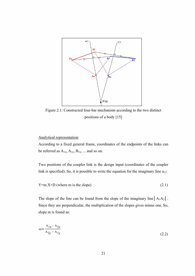
Figure 2.1: Constructed four-bar mechanism according to the two distinct
positions of a body [15]
Analytical representation:
According to a fixed general frame, coordinates of the endpoints of the links can
be referred as A1x, A1y, B1x, ... and so on.
Two positions of the coupler link is the design input (coordinates of the coupler
link is specified). So, it is possible to write the equation for the imaginary line a12:
Y=m.X+D (where m is the slope) (2.1)
The slope of the line can be found from the slope of the imaginary line│A1A2│.
Since they are perpendicular, the multiplication of the slopes gives minus one. So,
slope m is found as:
mA1x A2x−
A2y A1y− (2.2)
22
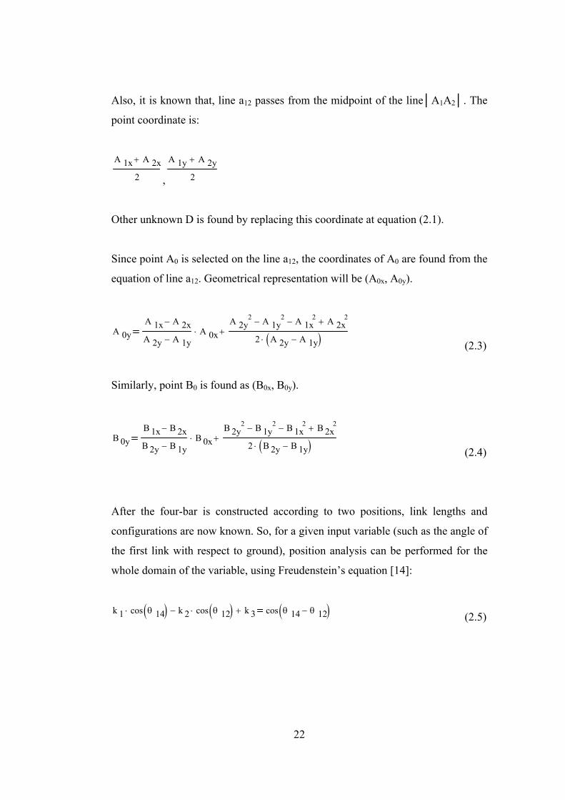
Also, it is known that, line a12 passes from the midpoint of the line│A1A2│. The
point coordinate is:
A 1x A 2x+
2 ,
A 1y A 2y+
2
Other unknown D is found by replacing this coordinate at equation (2.1).
Since point A0 is selected on the line a12, the coordinates of A0 are found from the
equation of line a12. Geometrical representation will be (A0x, A0y).
A 0yA 1x A 2x−
A 2y A 1y−A 0x⋅
A 2y2 A 1y
2− A 1x2− A 2x
2+
2 A 2y A 1y−( )⋅+
(2.3)
Similarly, point B0 is found as (B0x, B0y).
B 0yB 1x B 2x−
B 2y B 1y−B 0x⋅
B 2y2 B 1y
2− B 1x2− B 2x
2+
2 B 2y B 1y−( )⋅+
(2.4)
After the four-bar is constructed according to two positions, link lengths and
configurations are now known. So, for a given input variable (such as the angle of
the first link with respect to ground), position analysis can be performed for the
whole domain of the variable, using Freudenstein’s equation [14]:
k 1 cos θ 14( )⋅ k 2 cos θ 12( )⋅− k 3+ cos θ 14 θ 12−( ) (2.5)
23
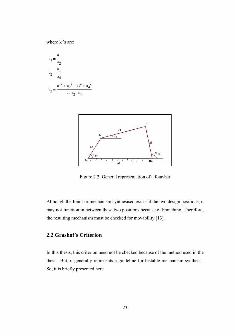
where ki’s are:
k1a1a2
k2a1a4
k3a1
2 a22+ a3
2− a42+
2 a2⋅ a4⋅
Figure 2.2: General representation of a four-bar
Although the four-bar mechanism synthesised exists at the two design positions, it
may not function in between these two positions because of branching. Therefore,
the resulting mechanism must be checked for movability [13].
2.2 Grashof’s Criterion
In this thesis, this criterion need not be checked because of the method used in the
thesis. But, it generally represents a guideline for bistable mechanism synthesis.
So, it is briefly presented here.
24
Consider a four-bar mechanism, where symbols represent the following:
s: shortest link length
l: longest link length
p,q: other two link lengths
The mechanism is said to be a Grashof mechanism if following relation holds:
s+l ≤ p+q (2.6)
The mechanism is called non-Grashof otherwise.
In a Grashof mechanism, the shortest link can rotate 360o with respect to any
other link connected to it. In a non-Grashof mechanism no link can rotate through
a full revolution [14].
If the four-bar mechanism is a Grashof mechanism, torsional spring must be
located opposite the shortest link and when spring is undeflected, shortest and
other link connected to it and opposite the spring must be non-collinear (for one
spring in the system), in order to obtain bistable behaviour. If the four-bar
mechanism is a non-Grashof mechanism, when spring is undeflected, two links
opposite the spring must be non-collinear (for one spring in the system), in order
to obtain bistable behaviour. Proof can be seen at [3].
There can be more than one spring in the system, as long as the above criterion is
satisfied. For a fully compliant bistable four-bar, in all cases there exists a
solution for bistability.
25
2.3 Stability
Stable position of a mechanism means that, for a small shift from the position, the
mechanism tends to return to its undisturbed position.
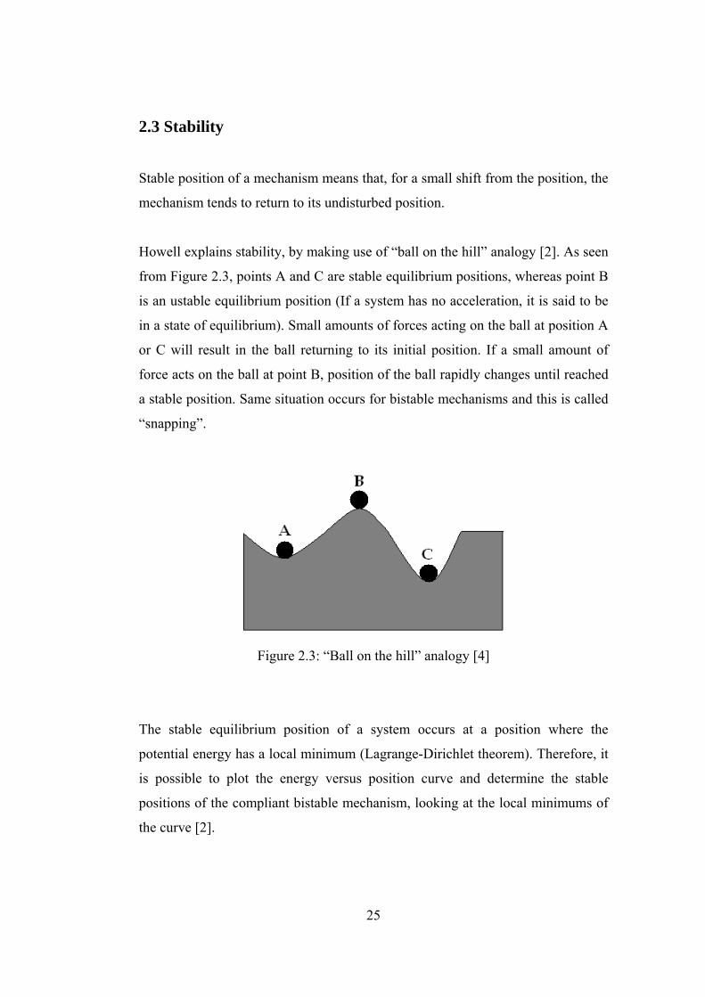
Howell explains stability, by making use of “ball on the hill” analogy [2]. As seen
from Figure 2.3, points A and C are stable equilibrium positions, whereas point B
is an ustable equilibrium position (If a system has no acceleration, it is said to be
in a state of equilibrium). Small amounts of forces acting on the ball at position A
or C will result in the ball returning to its initial position. If a small amount of
force acts on the ball at point B, position of the ball rapidly changes until reached
a stable position. Same situation occurs for bistable mechanisms and this is called
“snapping”.
Figure 2.3: “Ball on the hill” analogy [4]
The stable equilibrium position of a system occurs at a position where the
potential energy has a local minimum (Lagrange-Dirichlet theorem). Therefore, it
is possible to plot the energy versus position curve and determine the stable
positions of the compliant bistable mechanism, looking at the local minimums of
the curve [2].
26
Total potential energy of a mechanism can be found by summing potential energy
of each segment.
VT=V1+V2+V3+.... (2.7)
For a compliant mechanism, potential energy of each segment, using pseudo-
rigid-body model, is found as [8]:
V12
⎛⎜⎝
⎞⎠
K⋅ Ψ2
⋅ (2.8)
where:
K: torsional spring constant (which is assumed to be constant)
ψ: relative deflection of the segment (pseudo-rigid-body angle)
If only one spring is present, mechanism will always have zero potential energy at
both stable positions.
2.4 Pseudo Rigid Body Model of Compliant Segment Types
There are many different kinds of compliant segment types that can be modelled
using pseudo rigid body model. But, especially two of them are very useful for
compliant four-bar synthesis:
- Small length flexural pivots
- Fixed-pinned links
27
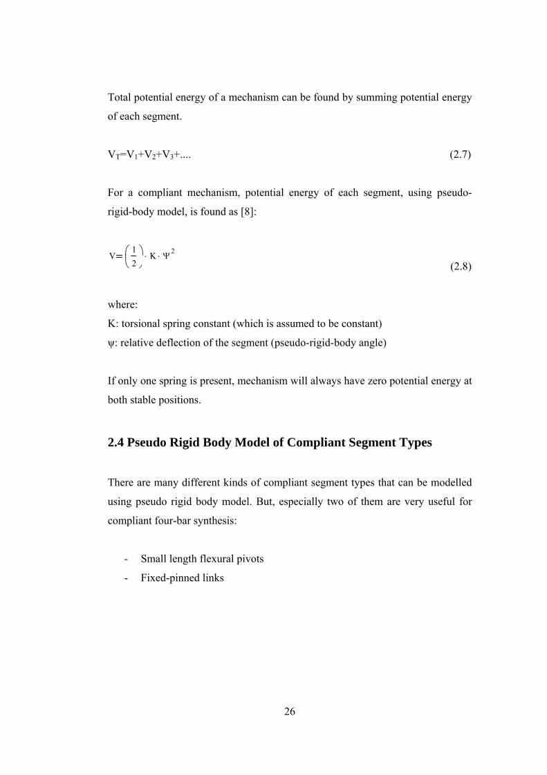
1. Small length flexural pivots:
(a) (b)
Figure 2.4: Pseudo-rigid-body model of a small-length flexural pivot [3]
Figure 2.4 (a) shows a small length flexural pivot and Figure 2.4 (b) is its pseudo-
rigid-body model. The torsional spring is positioned at the middle point of the
small length flexural pivot (as seen in Figure 2.4b). It is a good assumption and
gives enough accuracy in the calculations. Fixing the coordinate frame at point A
(ground connection point), the coordinates of the endpoint of the beam (Bx,By) is
found as [3]:
(2.9)
(2.10)
where:
ℓ: length of the flexural pivot
L: length of the link
Θ: deflection angle (pseudo rigid body angle)
A B
28
The torsional spring constant, K, is found as [3]:
(2.11)
where:
E: elasticity modulus
I: moment of inertia
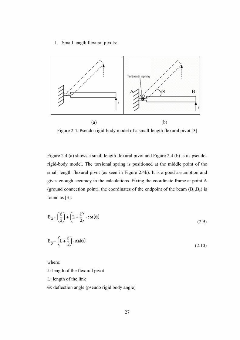
2. Fixed-pinned link:
Figure 2.5: Pseudo-rigid-body model of a fixed-pinned link [3]
For a fixed-pinned segment, the torsional spring is positioned at a certain distance
determined by the factor γ. Again fixing the coordinate frame at point A, endpoint
coordinates of the beam (Bx,By) can be found as [3]:
Bx L γ L⋅− γ L⋅ cos Θ( )⋅+ (2.12)
(2.13)
AB
By γ L⋅ sin Θ( )⋅
29
The value of γ on average is 0,85, for all loading conditions [3]. The torsional
spring constant for this case is approximately found as [3]:
K π γ2
⋅E I⋅
L⋅
(2.14)
2.5 Static Failure
The compliant segment must be checked for static failure. According to distortion
energy theory, effective stress σ’ (also referred as von Mises stress) has to be
greater than the yield strength (Sy) of the material, for static failure to occur [2].
σ’ ≥ Sy (for failure) (2.15)
σ’ can be found by using a finite element software.
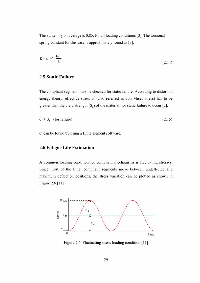
2.6 Fatigue Life Estimation
A common loading condition for compliant mechanisms is fluctuating stresses.
Since most of the time, compliant segments move between undeflected and
maximum deflection positions, the stress variation can be plotted as shown in
Figure 2.6 [11].
Figure 2.6: Fluctuating stress loading condition [11]
30
σm refers to mean stress and σa refers to alternating stress, where general
equations of them are given as [11]:
σmσmax σmin+
2
σaσmax σmin−
2
Since σmin=0 for the case shown in Figure 2.6, mean and alternating stresses can
be calculated as σm=σa=σmax/2.
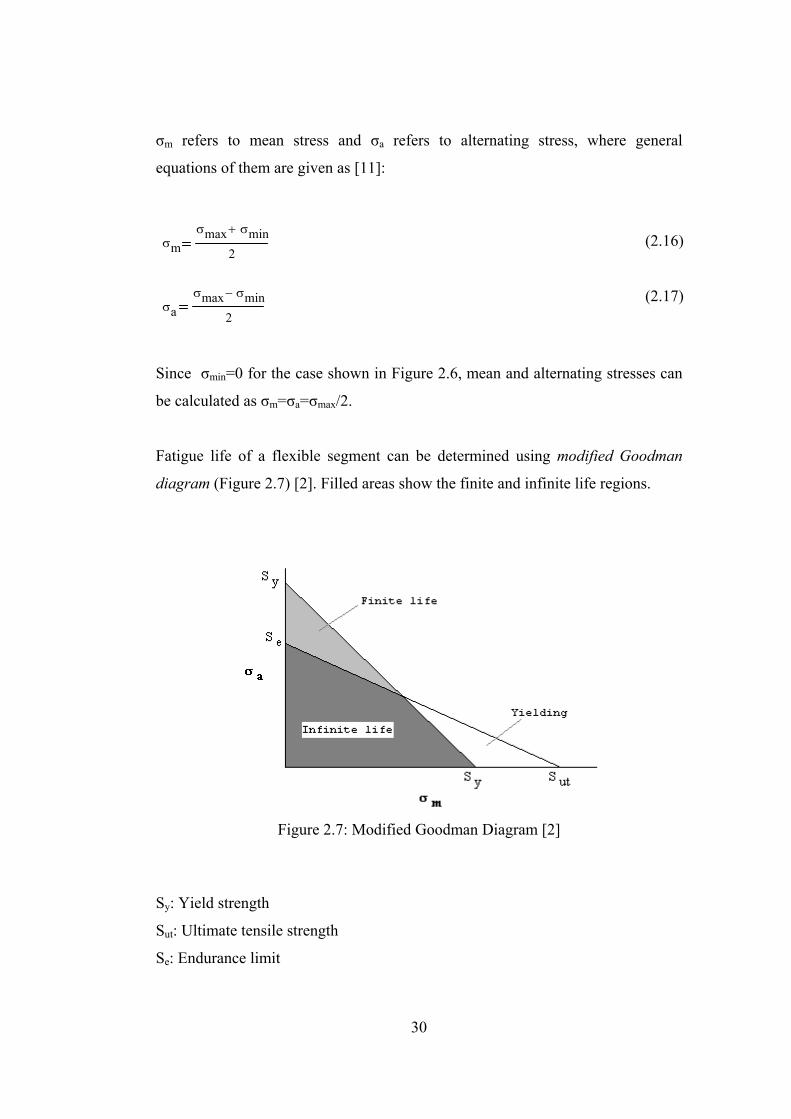
Fatigue life of a flexible segment can be determined using modified Goodman
diagram (Figure 2.7) [2]. Filled areas show the finite and infinite life regions.
Figure 2.7: Modified Goodman Diagram [2]
Sy: Yield strength
Sut: Ultimate tensile strength
Se: Endurance limit
(2.16)
(2.17)

31
Line passing through Se on σa axis and Sut on σm axis, is called modified Goodman
line and its equation is [11]:
σaSe
σmSut
+ 1 (2.18)
The safety factor for the modified Goodman line is:
1SF
σaSe
σmSut
+
(2.19)
For plastic parts it is recommended to use Se=0,2.Sut to Se=0,4.Sut [2]. Averagely
Se=0,3.Sut can be taken. Also taking σm=σa=σmax/2 and re-arranging equation
(2.19), safety factor can be calculated as:
SF6 Sut⋅
13 σmax⋅ (2.20)
Infinite life generally is assumed to start from 106 cycles in literature for a flexible
segment [11]. When safety factor is equal to one, it represents a point on the
modified Goodman line. So, when SF=1, it corresponds to 106 life cycles.
For every material, there is an S-N diagram available for different loading
conditions, in literature. Since they are dependent on experimental results, those
diagrams should be used whenever possible. If S-N diagrams are not available,
then modified Goodman method explained above can be preferred.
32
CHAPTER 3
DESIGN OF A COMPLIANT BISTABLE FOUR-BAR
Aim of this chapter is to introduce a design concept that can be used for two
position synthesis of a compliant bistable four link mechanism. Pseudo-rigid-body
model and potential energy equation corresponding to the model is used. There
are analysis methods using the same concept in the literature, but they are used to
define two stable positions of a constructed mechanism, whereas in this thesis,
mechanism is constructed for two positions and corresponding torsional spring
constants are calculated in order to realize that positions. An example is presented
which uses the developed design concept.
3.1 Potential Energy Equation
Generally, in order to find stable positions of a mechanism (if position and energy
equations are available), first and second derivatives of the potential energy
equation with respect to input variable is used. Equating the first derivative to
zero, gives the equilibrium positions. The positive magnitude of the second
derivative at the equilibrium positions shows that this equilibrium position is
stable [2].
The fully compliant four-bar mechanism is shown in Figure 3.1 (a). Its pseudo-
rigid body model is shown in Figure 3.1 (b).

33
(a) (b)
Figure 3.1: Pseudo-rigid-body model of a four-bar mechanism [2]
Total potential energy equation for the mechanism is given as [2]:
V12
K 1 ψ 12
⋅ K 2 ψ 22
⋅+ K 3 ψ 32
⋅+ K 4 ψ 42
⋅+⎛⎝
⎞⎠⋅
(3.1)
where:
ψ1 θ2 θ20−
ψ2 θ2 θ20−( ) θ3 θ30−( )−
ψ3 θ4 θ40−( ) θ3 θ30−( )−
ψ4 θ4 θ40−
“θio” refers to the initial (undeflected) position of the ith link.
Taking the derivative with respect to the independent variable (coupler link angle
θ3 is used as the independent variable, as it will be used as the input angle later):
dVdθ3
K1 ψ1⋅ A1⋅ K2 ψ2⋅ A1 1−( )⋅+ K3 ψ3⋅ A2 1−( )⋅+ K4 ψ4⋅ A2⋅+
(3.6)
a1
a2
a3
a4
(3.2)
(3.3)
(3.4)
(3.5)
34
where:
A1dθ2
dθ3
r3 sin θ3 θ4−( )⋅
r2 sin θ4 θ2−( )⋅
A2dθ4
dθ3
r3 sin θ3 θ2−( )⋅
r4 sin θ4 θ2−( )⋅
The first derivative is actually the input torque [2]. So:
T3dVdθ3 (3.9)
When first derivative of the total potential energy is equated to zero, a maximum,
a minimum or a saddle point is reached. The sign of the second derivative at this
position determines the type of stable position. If the value of the equation is
greater than zero, it represents a stable position, whereas if it is less than zero, it
represents an unstable position (snapping point).
Second derivative of the total potential energy equation with respect to θ3 can be
found as:
d2V
dθ32
K1 A12 ψ1 A3⋅+( )⋅ K2 A3 ψ2⋅ A1
2+ 2 A1⋅− 1+( )⋅+ K3 A4 ψ3⋅ A22+(⋅+
2 A2⋅− 1+ ) K4 A22 ψ4 A4⋅+( )⋅+ (3.10)
where:
A3r3r2
⎛⎜⎝
⎞
⎠
cos θ3 θ4−( )sin θ4 θ2−( )
1 A2−( )⋅sin θ3 θ4−( ) cos θ4 θ2−( )⋅
sin2 θ4 θ2−( )A2 A1−( )⋅−
⎡⎢⎢⎣
⎤⎥⎥⎦
⋅
(3.7)
(3.8)
(3.11)
35
A4r3r4
⎛⎜⎝
⎞
⎠
cos θ3 θ2−( )sin θ4 θ2−( )
1 A1−( )⋅sin θ3 θ2−( ) cos θ4 θ2−( )⋅
sin2 θ4 θ2−( )A2 A1−( )⋅−
⎡⎢⎢⎣
⎤⎥⎥⎦
⋅
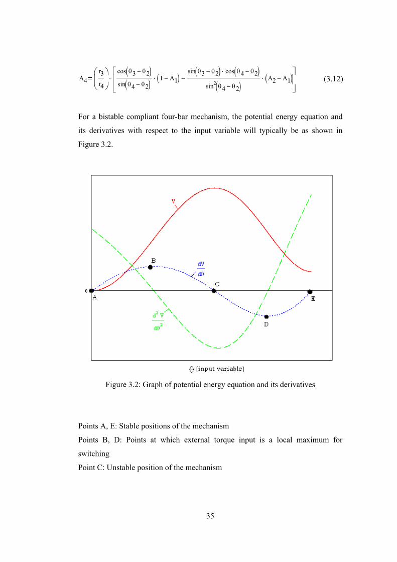
For a bistable compliant four-bar mechanism, the potential energy equation and
its derivatives with respect to the input variable will typically be as shown in
Figure 3.2.
Figure 3.2: Graph of potential energy equation and its derivatives
Points A, E: Stable positions of the mechanism
Points B, D: Points at which external torque input is a local maximum for
switching
Point C: Unstable position of the mechanism
(3.12)

36
For every bistable mechanism, an unstable position is also present. A bistable
mechanism snaps between stable positions through the unstable position.
3.2 Design Steps
The input is the two stable positions and force required to snap the mechanism
between two positions. The intend is to find the torsional spring constants as
given in Pseudo-rigid-body model and corresponding dimensional properties of
joints and links. Then maximum stress analysis can be performed to estimate
fatigue life of the mechanism. Design steps will be realized in the next section,
where an example is presented.
The basic design algorithm is:
- Deciding the number of torsional springs that is intended to be used on the
mechanism.
- Deciding on the two coupler joint positions on the body.
- Choosing initial position of the input link (one of the bistable positions).
- Selecting one of the ground joint connections A0 or B0 (can be found by
using Chasle’s theorem).
- Changing the position of the other ground joint connection until input
torque requirement is met (iteration step).
- Predicting the unknown torsional spring constants by making use of the
derivative of the total potential energy (torque) equation.
- Choosing material for the mechanism and segment types for the joints and
finding compliant joint and link dimensions.
- Checking for static failure and performing fatigue life analysis.
Regarding the design steps, it is always possible to turn back to previous steps and
choose different positions or variables until all design criteria are met. For
37
example, choosing different number of torsional springs, choosing different
coupler positions, changing the starting position, choosing different joint
connections (A0, B0) or choosing different material or segment types is possible.
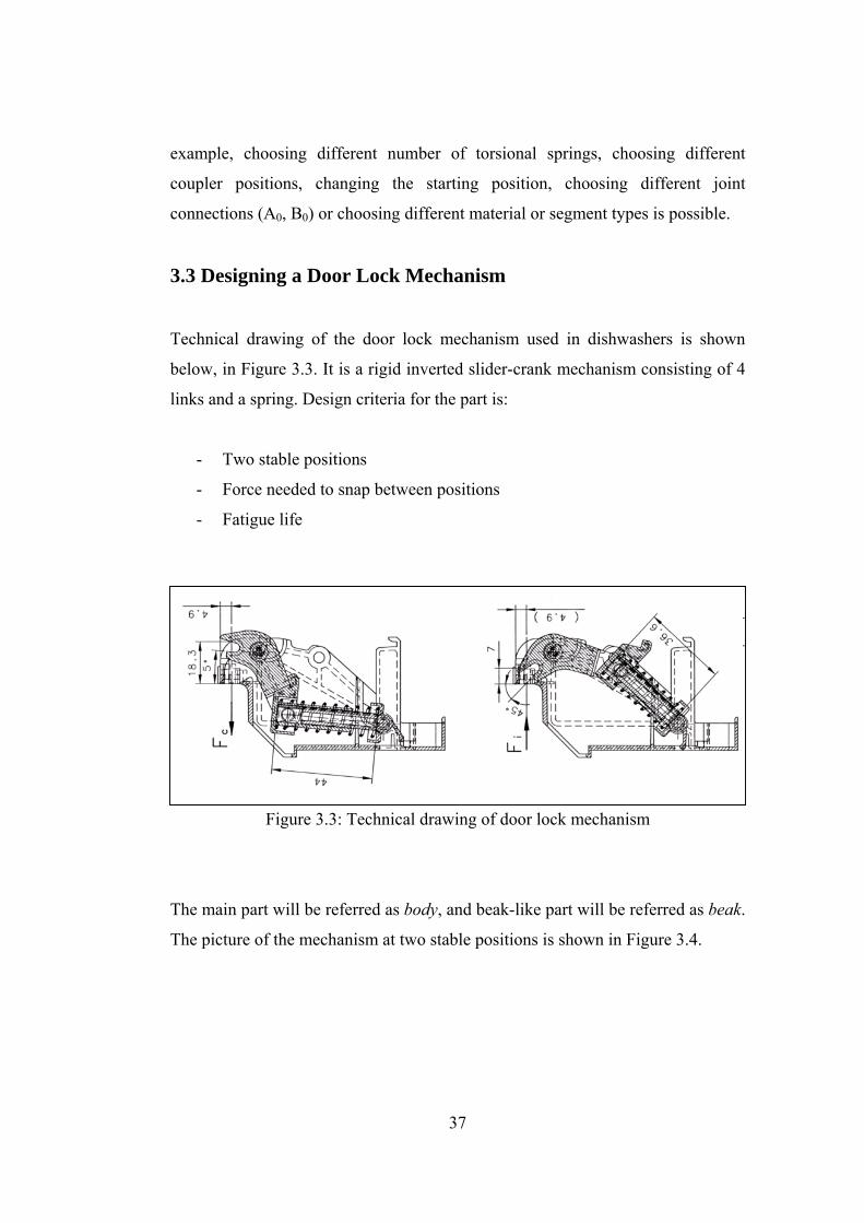
3.3 Designing a Door Lock Mechanism
Technical drawing of the door lock mechanism used in dishwashers is shown
below, in Figure 3.3. It is a rigid inverted slider-crank mechanism consisting of 4
links and a spring. Design criteria for the part is:
- Two stable positions
- Force needed to snap between positions
- Fatigue life
Figure 3.3: Technical drawing of door lock mechanism
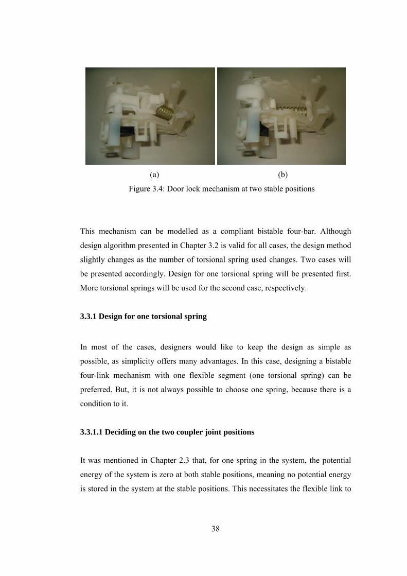
The main part will be referred as body, and beak-like part will be referred as beak.
The picture of the mechanism at two stable positions is shown in Figure 3.4.
38
(a) (b)
Figure 3.4: Door lock mechanism at two stable positions
This mechanism can be modelled as a compliant bistable four-bar. Although
design algorithm presented in Chapter 3.2 is valid for all cases, the design method
slightly changes as the number of torsional spring used changes. Two cases will
be presented accordingly. Design for one torsional spring will be presented first.
More torsional springs will be used for the second case, respectively.
3.3.1 Design for one torsional spring
In most of the cases, designers would like to keep the design as simple as
possible, as simplicity offers many advantages. In this case, designing a bistable
four-link mechanism with one flexible segment (one torsional spring) can be
preferred. But, it is not always possible to choose one spring, because there is a
condition to it.
3.3.1.1 Deciding on the two coupler joint positions
It was mentioned in Chapter 2.3 that, for one spring in the system, the potential
energy of the system is zero at both stable positions, meaning no potential energy
is stored in the system at the stable positions. This necessitates the flexible link to
39
be undeflected at the stable positions. So, in order to make a design made of one
torsional spring, the “pole” (as mentioned in Chapter 2.1) of the coupler has to be
chosen as the flexible link’s joint.
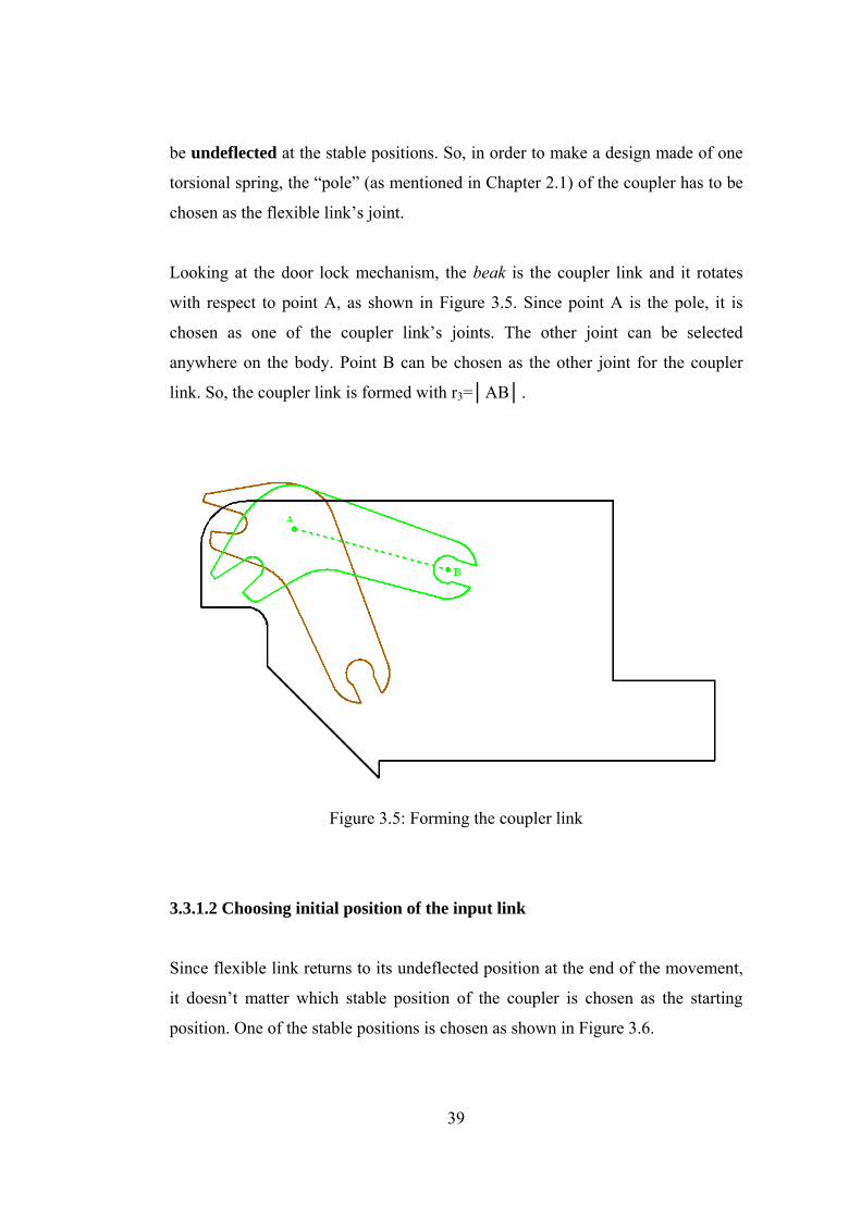
Looking at the door lock mechanism, the beak is the coupler link and it rotates
with respect to point A, as shown in Figure 3.5. Since point A is the pole, it is
chosen as one of the coupler link’s joints. The other joint can be selected
anywhere on the body. Point B can be chosen as the other joint for the coupler
link. So, the coupler link is formed with r3=│AB│.
Figure 3.5: Forming the coupler link
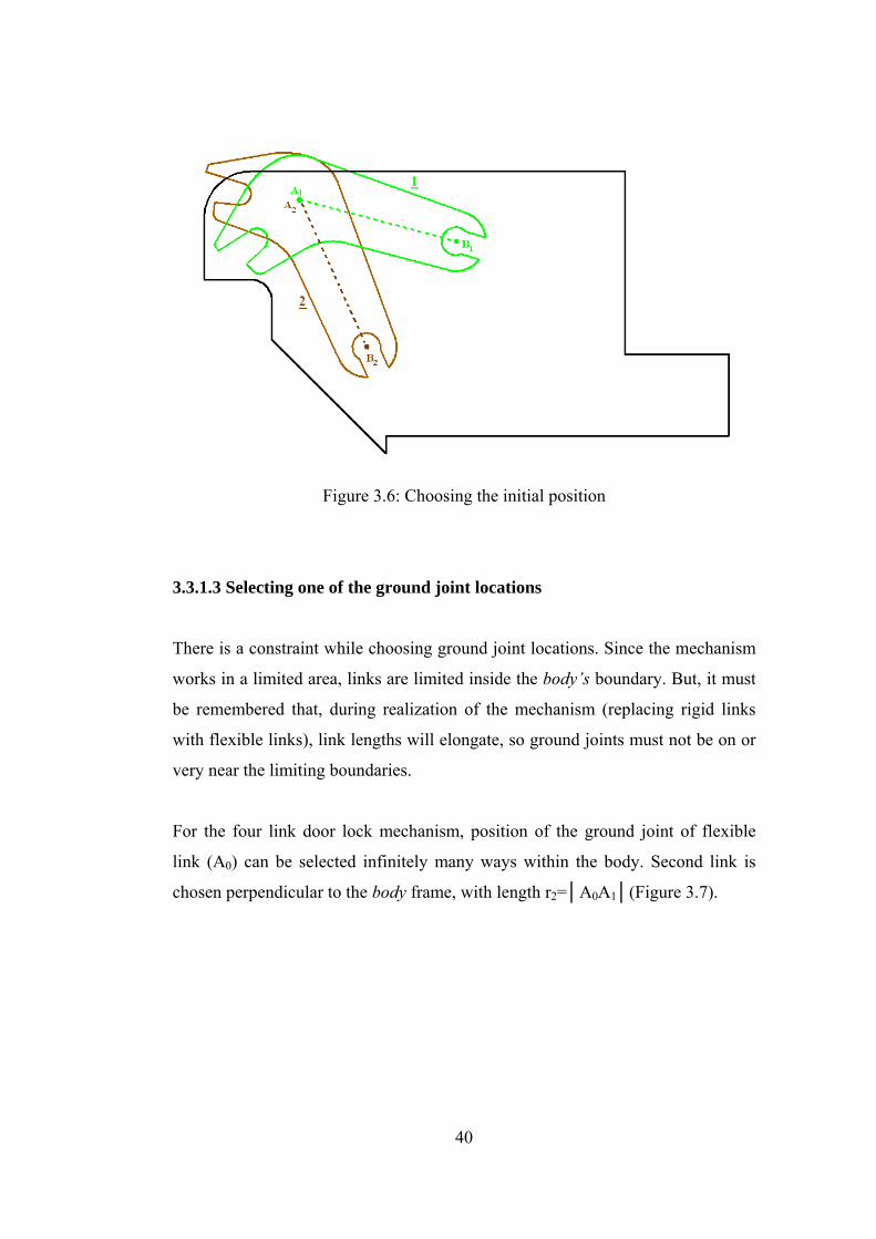
3.3.1.2 Choosing initial position of the input link
Since flexible link returns to its undeflected position at the end of the movement,
it doesn’t matter which stable position of the coupler is chosen as the starting
position. One of the stable positions is chosen as shown in Figure 3.6.
40
Figure 3.6: Choosing the initial position
3.3.1.3 Selecting one of the ground joint locations
There is a constraint while choosing ground joint locations. Since the mechanism
works in a limited area, links are limited inside the body’s boundary. But, it must
be remembered that, during realization of the mechanism (replacing rigid links
with flexible links), link lengths will elongate, so ground joints must not be on or
very near the limiting boundaries.
For the four link door lock mechanism, position of the ground joint of flexible
link (A0) can be selected infinitely many ways within the body. Second link is
chosen perpendicular to the body frame, with length r2=│A0A1│(Figure 3.7).
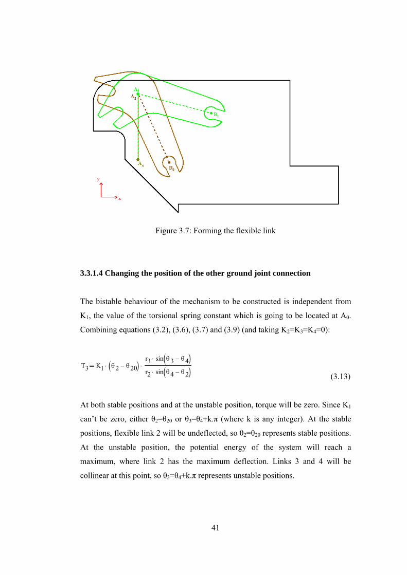
41
Figure 3.7: Forming the flexible link
3.3.1.4 Changing the position of the other ground joint connection
The bistable behaviour of the mechanism to be constructed is independent from
K1, the value of the torsional spring constant which is going to be located at A0.
Combining equations (3.2), (3.6), (3.7) and (3.9) (and taking K2=K3=K4=0):
T3 K1 θ2 θ20−( )⋅r3 sin θ3 θ4−( )⋅
r2 sin θ4 θ2−( )⋅⋅
(3.13)
At both stable positions and at the unstable position, torque will be zero. Since K1
can’t be zero, either θ2=θ20 or θ3=θ4+k.π (where k is any integer). At the stable
positions, flexible link 2 will be undeflected, so θ2=θ20 represents stable positions.
At the unstable position, the potential energy of the system will reach a
maximum, where link 2 has the maximum deflection. Links 3 and 4 will be
collinear at this point, so θ3=θ4+k.π represents unstable positions.
42
K1 is only a scale factor that determines the maximum torque values between
switching.
In order to construct a four-bar mechanism, only one varible is needed to be fixed
at this point. It is the position of the other ground joint connection (B0). When B0
is selected; link lengths r1 and r4, and all angle relations can be determined. Then
the mechanism is analysed between stable positions to find torque curve
characteristics. So, an iteration has to be made in a certain range, until force
requirements are fulfilled.
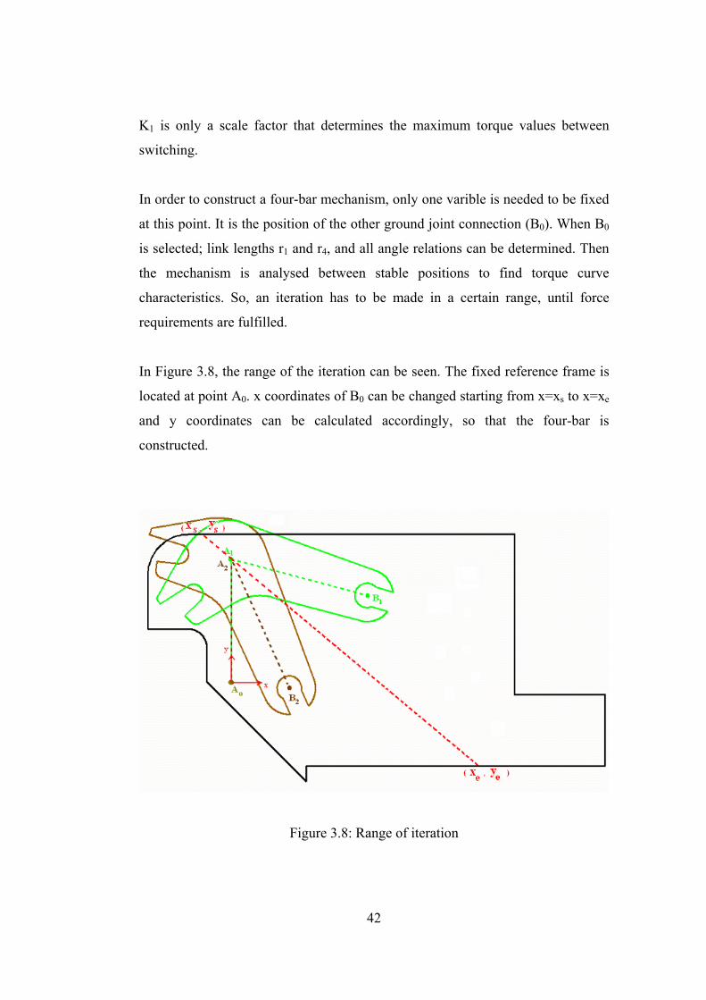
In Figure 3.8, the range of the iteration can be seen. The fixed reference frame is
located at point A0. x coordinates of B0 can be changed starting from x=xs to x=xe
and y coordinates can be calculated accordingly, so that the four-bar is
constructed.
Figure 3.8: Range of iteration
43
Before the iteration, torque of link 3 has to be expressed in terms of force applied
at the end of the beak, since force is the objective function. Also, force need not to
be at a maximum where torque is maximum, so it has to be analysed seperately.
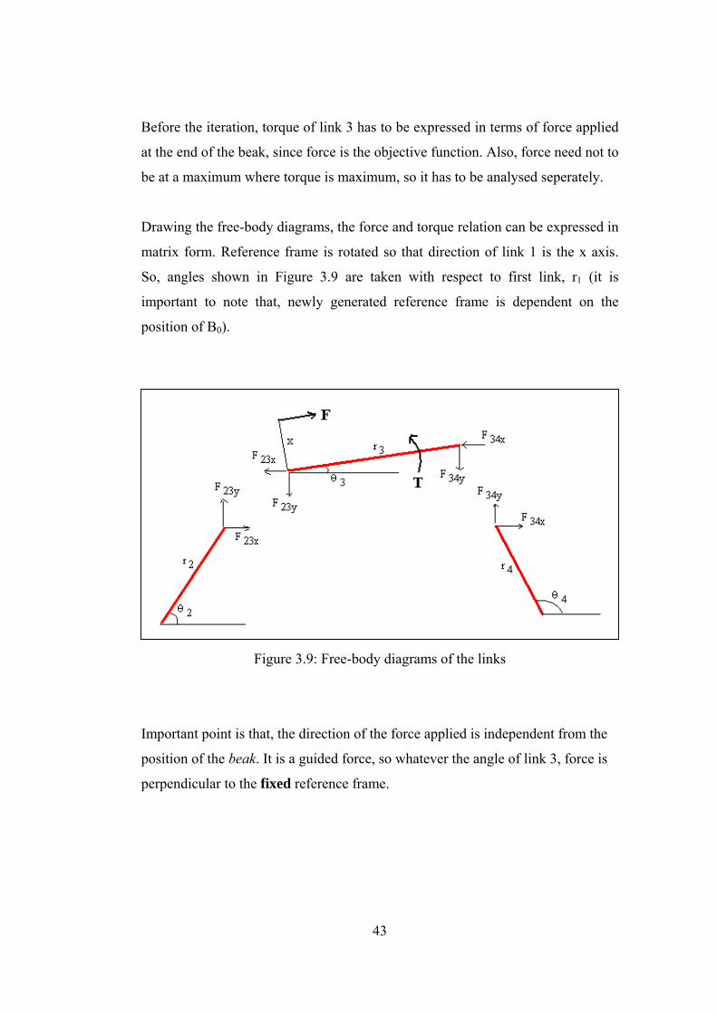
Drawing the free-body diagrams, the force and torque relation can be expressed in
matrix form. Reference frame is rotated so that direction of link 1 is the x axis.
So, angles shown in Figure 3.9 are taken with respect to first link, r1 (it is
important to note that, newly generated reference frame is dependent on the
position of B0).
Figure 3.9: Free-body diagrams of the links
Important point is that, the direction of the force applied is independent from the
position of the beak. It is a guided force, so whatever the angle of link 3, force is
perpendicular to the fixed reference frame.
44
r2− sinθ2⋅
0
1−
0
0
r2 cos θ2⋅
0
0
1−
0
0
r4− sinθ4⋅
1−
0
r3 sinθ3⋅
0
r4 cosθ4⋅
0
1−
r3− cosθ3⋅
0
0
cos 90 θ1−( )sin 90 θ1−( )
x−
⎛⎜⎜⎜⎜⎜⎜⎜⎝
⎞
⎟⎟⎟⎟⎟
⎠
F23x
F23y
F34x
F34y
F
⎛⎜⎜⎜⎜⎜⎜⎝
⎞
⎟⎟⎟⎟
⎠
⋅
0
0
0
0
T3−
⎛⎜⎜⎜⎜⎜⎝
⎞
⎟⎟⎟
⎠
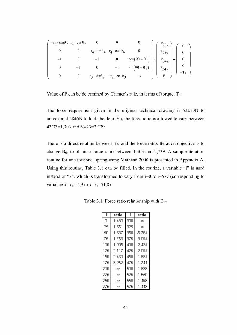
Value of F can be determined by Cramer’s rule, in terms of torque, T3.
The force requirement given in the original technical drawing is 53±10N to
unlock and 28±5N to lock the door. So, the force ratio is allowed to vary between
43/33=1,303 and 63/23=2,739.
There is a direct relation between B0x and the force ratio. Iteration objective is to
change B0x to obtain a force ratio between 1,303 and 2,739. A sample iteration
routine for one torsional spring using Mathcad 2000 is presented in Appendix A.
Using this routine, Table 3.1 can be filled. In the routine, a variable “i” is used
instead of “x”, which is transformed to vary from i=0 to i=577 (corresponding to
variance x=xs=-5,9 to x=xe=51,8)
Table 3.1: Force ratio relationship with B0x
45
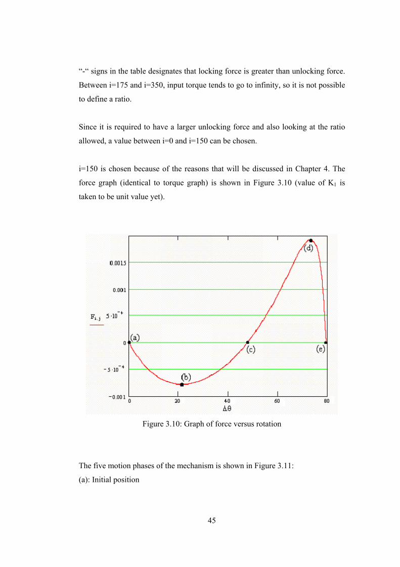
“-“ signs in the table designates that locking force is greater than unlocking force.
Between i=175 and i=350, input torque tends to go to infinity, so it is not possible
to define a ratio.
Since it is required to have a larger unlocking force and also looking at the ratio
allowed, a value between i=0 and i=150 can be chosen.
i=150 is chosen because of the reasons that will be discussed in Chapter 4. The
force graph (identical to torque graph) is shown in Figure 3.10 (value of K1 is
taken to be unit value yet).
Figure 3.10: Graph of force versus rotation
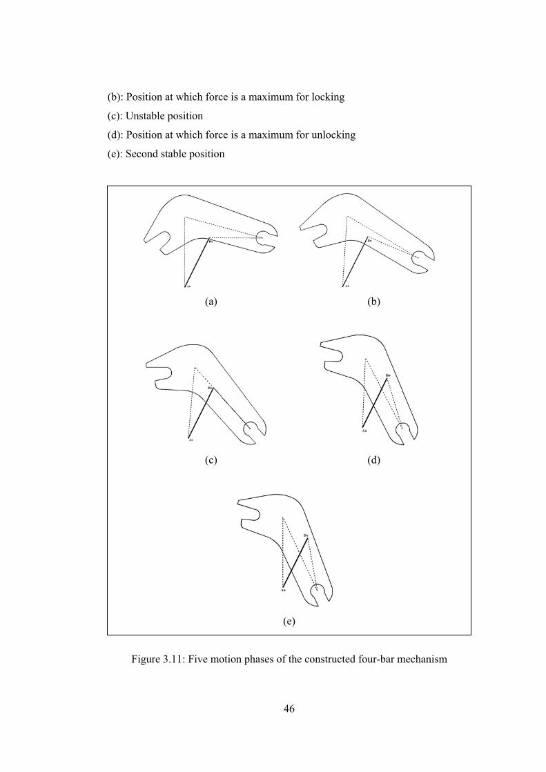
The five motion phases of the mechanism is shown in Figure 3.11:
(a): Initial position
46
(b): Position at which force is a maximum for locking
(c): Unstable position
(d): Position at which force is a maximum for unlocking
(e): Second stable position
(a) (b)
(c) (d)
(e)
Figure 3.11: Five motion phases of the constructed four-bar mechanism
47
3.3.1.5 Predicting the value of the torsional spring constant
Maximum force to lock and unlock the mechanism is known in terms of K1.
When K1 is taken as unit value, Flock-max and Funlock-max can be calculated as (also
seen from the graph shown in Figure 3.10):
Flock-max = 7.83x10⁻⁴ N
Funlock-max = 19.27x10⁻⁴ N
Value of K1 is directly proportional to these forces, as seen from equation (3.13)
and the matrix equation. If K1=32000 N.mm is chosen then the forces become:
Flock-max = 25.06 N
Funlock-max = 61.65 N
which are acceptable according to the given force tolerances at the technical
drawing shown in Figure A.1.
3.3.1.6 Realizing the mechanism
Since necessary parameters are calculated, it is possible to build the mechanism
with compliant segments. The material of the mechanism is chosen to be
polyoxymethylene, POM (Delrin). Its Young’s modulus is E=2300 N/mm2.
Material properties of some commercially available materials are listed in
Appendix C.
Segment type will be chosen for the link that have the torsional spring. There are
two important rules to remember while constructing the mechanism:
1. In pseudo-rigid-body model, when switching from rigid mechanism with
torsional springs to actual mechanism, lengths of the flexible links differ.
48
2. As the pseudo-rigid-body model theory is about compliant segments that
are perpendicular to connections, the links must be formed so that they are
always perpendicular to its connectors (whether fixed or not).
For the constructed door lock mechanism, link 2 can be chosen as a small-length-
flexural pivot or a fixed-pinned link. Fixed-pinned link has generally better
fatigue resistance than small-length-flexural pivot, so it can be chosen.
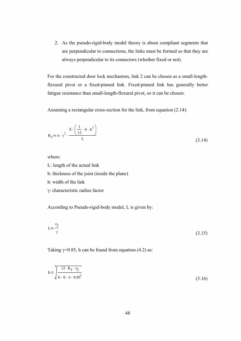
Assuming a rectangular cross-section for the link, from equation (2.14):
K1 π γ2
⋅
E112
b⋅ h3⋅⎛⎜⎝
⎞⎠
⋅
L⋅
(3.14)
where:
L: length of the actual link
b: thickness of the joint (inside the plane)
h: width of the link
γ: characteristic radius factor
According to Pseudo-rigid-body model, L is given by:
Lr2γ (3.15)
Taking γ=0.85, h can be found from equation (4.2) as:
h3 12 K1⋅ r2⋅
b E⋅ π⋅ 0.853⋅ (3.16)
49
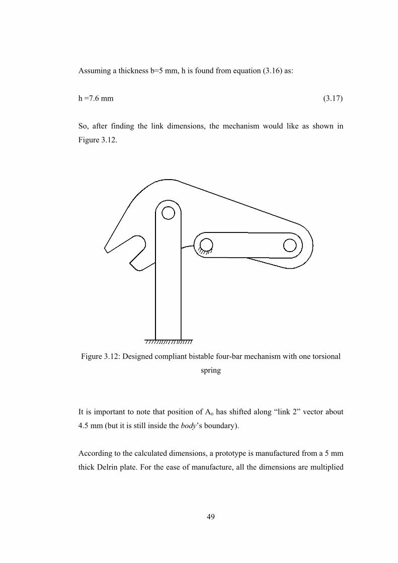
Assuming a thickness b=5 mm, h is found from equation (3.16) as:
h =7.6 mm (3.17)
So, after finding the link dimensions, the mechanism would like as shown in
Figure 3.12.
Figure 3.12: Designed compliant bistable four-bar mechanism with one torsional
spring
It is important to note that position of Ao has shifted along “link 2” vector about
4.5 mm (but it is still inside the body’s boundary).
According to the calculated dimensions, a prototype is manufactured from a 5 mm
thick Delrin plate. For the ease of manufacture, all the dimensions are multiplied
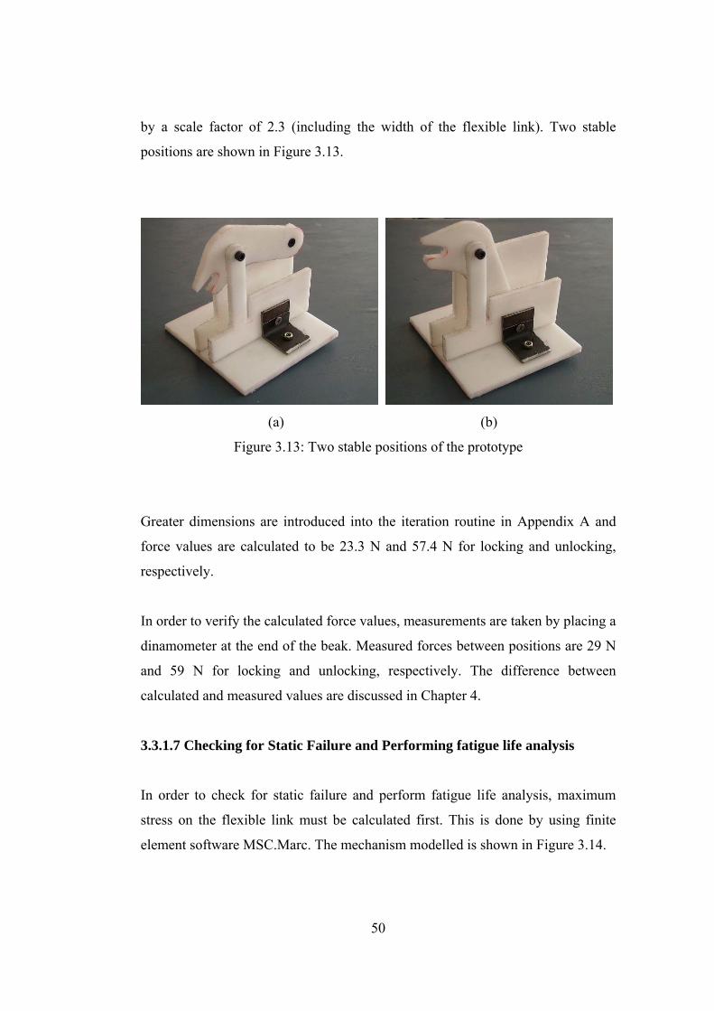
50
by a scale factor of 2.3 (including the width of the flexible link). Two stable
positions are shown in Figure 3.13.
(a) (b)
Figure 3.13: Two stable positions of the prototype
Greater dimensions are introduced into the iteration routine in Appendix A and
force values are calculated to be 23.3 N and 57.4 N for locking and unlocking,
respectively.
In order to verify the calculated force values, measurements are taken by placing a
dinamometer at the end of the beak. Measured forces between positions are 29 N
and 59 N for locking and unlocking, respectively. The difference between
calculated and measured values are discussed in Chapter 4.
3.3.1.7 Checking for Static Failure and Performing fatigue life analysis
In order to check for static failure and perform fatigue life analysis, maximum
stress on the flexible link must be calculated first. This is done by using finite
element software MSC.Marc. The mechanism modelled is shown in Figure 3.14.

51
Figure 3.14: Mechanism modelled in MSC.Marc
Maximum stress occurs at the maximum deflection position, which is the unstable
position of the mechanism (Figure 3.15b). Stable position, on the other hand, is
the minimum stress position (Figure 3.15a).
(a) (b)
Figure 3.15: Minimum and maximum stress positions of the flexible link
52
According to the finite element model, maximum effective stress is σ’= 46,4 Mpa
(Figure 3.15b). Yield strength of POM is given by (Table C.1) Sy = 60 Mpa. So,
inequality (2.15) does not hold and there is no static failure.
Fatigue life of the door lock mechanism is required to be at least 105 cycles,
according to technical specs. Taking Sut=70 Mpa (Table C.1) and putting it into
equation (2.20):
SF6 70⋅
13 46.4⋅0.696
(3.18)
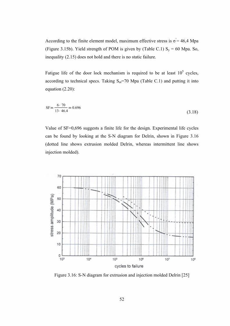
Value of SF=0,696 suggests a finite life for the design. Experimental life cycles
can be found by looking at the S-N diagram for Delrin, shown in Figure 3.16
(dotted line shows extrusion molded Delrin, whereas intermittent line shows
injection molded).
Figure 3.16: S-N diagram for extrusion and injection molded Delrin [25]

53
x=3x10⁵ cycles is found. It is greater than the required value of 105 cycles, so the
design is on the safe side when fatigue is concerned.
3.3.2 Design for several torsional springs
Unlike one torsional spring case, if the number of torsional springs are increased,
bistable behaviour will depend not only on the constructed mechanism, but also
the number and value of the torsional springs. So, force ratio is not only a
function of coordinates of ground joint, but also a function of the value of
torsional springs for this case.
Only synthesis of the mechanism in Pseudo-rigid body model form is presented in
this section. The realization part has many versatilities (like different number of
torsional springs, different spring locations or different segment types) and an
example is presented in Appendix D.
3.3.2.1 Deciding on the two coupler joint positions
One of the stable positions of the designed mechanism will be where the flexible
links or joints are undeflected. The other stable position will be where the flexible
links or joints are deflected to some extent. It is a position that the forces
generated on the links come to an equilibrium point. “Pole” of the beak cannot be
chosen as one of the coupler link joints this time, since all the flexible links have
to be deflected in order to reach an equilibrium.
Two coupler joints can be selected anywhere on the body. Points A and B can be
chosen as the joints for the coupler link, as shown in Figure 3.16. So, the coupler
link is formed with r3=│AB│.
54
Figure 3.16: Forming the coupler link
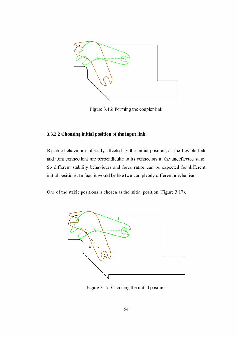
3.3.2.2 Choosing initial position of the input link
Bistable behaviour is directly effected by the initial position, as the flexible link
and joint connections are perpendicular to its connectors at the undeflected state.
So different stability behaviours and force ratios can be expected for different
initial positions. In fact, it would be like two completely different mechanisms.
One of the stable positions is chosen as the initial position (Figure 3.17).
Figure 3.17: Choosing the initial position
55
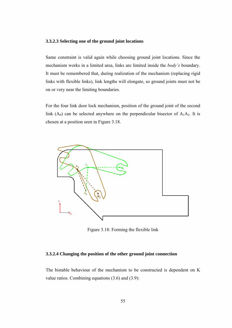
3.3.2.3 Selecting one of the ground joint locations
Same constraint is valid again while choosing ground joint locations. Since the
mechanism works in a limited area, links are limited inside the body’s boundary.
It must be remembered that, during realization of the mechanism (replacing rigid
links with flexible links), link lengths will elongate, so ground joints must not be
on or very near the limiting boundaries.
For the four link door lock mechanism, position of the ground joint of the second
link (A0) can be selected anywhere on the perpendicular bisector of A1A2. It is
chosen at a position seen in Figure 3.18.
Figure 3.18: Forming the flexible link
3.3.2.4 Changing the position of the other ground joint connection
The bistable behaviour of the mechanism to be constructed is dependent on K
value ratios. Combining equations (3.6) and (3.9):
56
T3 K1 ψ1⋅ A1⋅ K2 ψ2⋅ A1 1−( )⋅+ K3 ψ3⋅ A2 1−( )⋅+ K4 ψ4⋅ A2⋅+ (3.19)
If K3=K4=0, then the equation will reduce to:
T3 K1 ψ1⋅ A1⋅ K2 ψ2⋅ A1 1−( )⋅+ (3.20)
The torque value will be zero at the stable and unstable positions. But, K1 and K2
can’t be zero or take a negative value. So, the only way to make equation (3.20)
equal to zero is to search for a certain K1/K2 ratio that will make T3=0 at the
unstable and stable positions. This ratio can be found by evaluating the
coefficients of K’s throughout the motion of the constructed mechanism at the
iteration point.
After finding this ratio, values of K’s can be adjusted to alter maximum torque
values between switching.
In order to construct a four-bar mechanism, an iteration will be made again for the
other ground joint connection (B0). When B0 is selected; link lengths r1 and r4, and
all angle relations can be determined. Iteration range is again the same as shown
in Figure 3.8 (as point B is chosen the same as previous case).
Coupler force relation to coupler torque can be found by using free-body
diagrams of the links, as shown in Figure 3.9.
A sample iteration routine for many torsional springs using Mathcad 2000 is
presented in Appendix B. Using this routine, the coefficients of K’s as presented
in equation (3.19) are found throughout the motion of the mechanism between
stable positions.

57
For example, if the iteration variable i=0 is chosen, the coefficient graphs will
look like as shown in Figure 3.19 (coefficients are referred as Cn, where n
represents the n’th torsional spring).
Figure 3.19: Variation of coefficients in torque equation with respect to rotation
when i=0
Looking at the graph it is seen that, all the coefficient values have negative value
at the end of the motion, except C3. In order to make torque equal to zero at the
end of the motion, torsional spring K3 has to be chosen along with any other
spring.
58
If K1=K2=0, then at the second stable position:
C4C3
0.95346−
0.6603214.44−
(3.21)
Since T3=C3.K3+C4.K4=0,
K3K4
C4−
C314.44
(3.22)
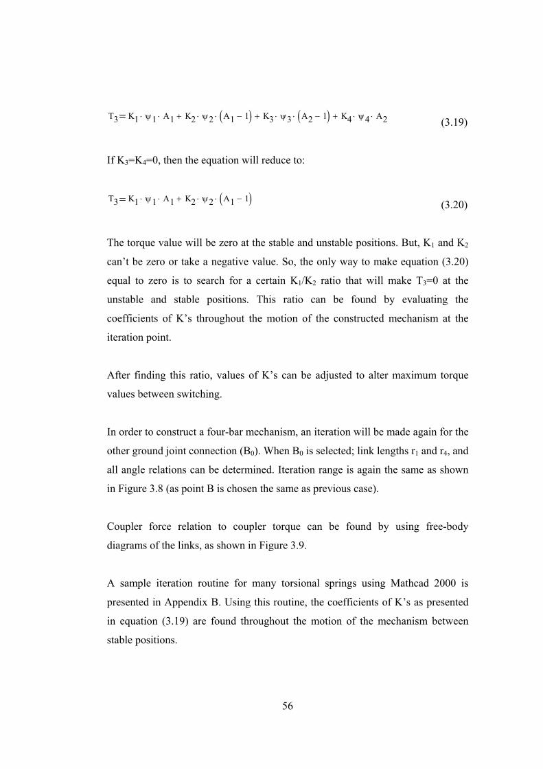
When K4=1 and K3=14.44 is taken, the force versus rotation graph will look like
as shown in Figure 3.20.
Figure 3.20: Force graph when i=0
59
Bistable behaviour is not reached as seen from Figure 3.20. Similar situations
would occur if K1, K2 or both were selected not to be equal to zero. It seems that,
a bistable behaviour cannot be reached when i=0.
Similarly if i=100 is chosen, coefficient values tend to go to infinity. So, i=100
cannot be selected.
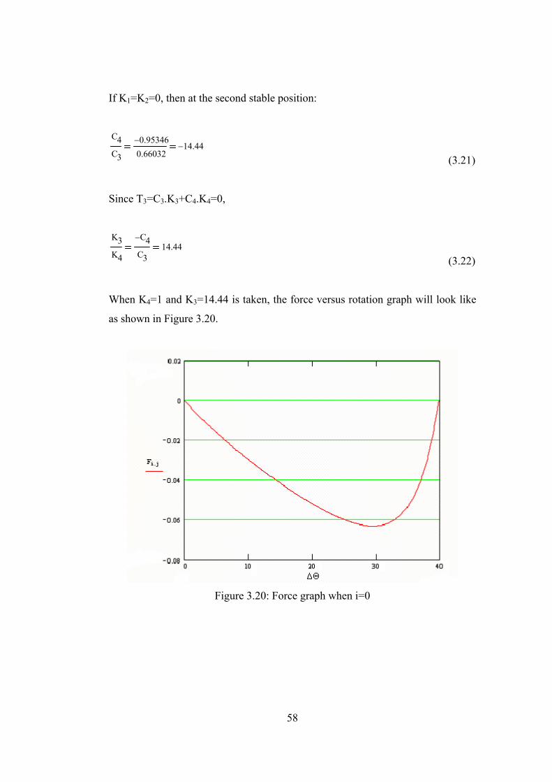
Iteration for “i” goes on until a suitable position or positions are found. When
i=53 is chosen, the coefficient graphs will look like as shown in Figure 3.21.
Figure 3.21: Variation of coefficients in torque equation with respect to rotation
when i=53

60
Looking at the graphs, K2=K4=0 can be taken. So, ratio between other torsional
springs is found as, K3/K1=36.68
Taking K1=1 and K3=36.68, the force versus rotation graph is plotted like as
shown in Figure 3.22.
Figure 3.22: Force graph when i=53
So, bistable behaviour is reached with a force ratio of 1.56. It is an acceptable
value, as it lies within tolerances as mentioned in section 3.3.1.4.
3.3.2.5 Predicting the value of the torsional spring constants
Maximum force to lock and unlock the mechanism is known in terms of K1 and
K3. When they are taken 1 and 36.68 respectively, Flock-max and Funlock-max can be
calculated as:
61
Flock-max = 2.2x10⁻² N
Funlock-max = 3.4x10⁻² N
Value of K’s are directly proportional with these forces. If K1=1300 N.mm and
K3=47700 N.mm are chosen then the forces become:
Flock-max = 28.55 N
Funlock-max = 44.56 N
which are acceptable according to the given force tolerances at the technical
drawing shown in Figure A.1.
62
CHAPTER 4
DISCUSSION AND CONCLUSION
Analysis of compliant mechanisms have many difficulties, as both kinematic and
deflection theory are needed. Synthesis is even harder, as many constraints are
introduced. The purpose of this study was to present a design approach that can be
used synthesising a compliant bistable four-link mechanism. Related work is
present in literature, but the method is different in this thesis.
Pseudo-rigid body model was used to come up with a design method. Pseudo-
rigid body model has the advantage that, rigid body kinematics theory is
applicable on the mechanism. But, it has some limitations. Accuracy of the end
coordinates of the flexible link is dependent on the position of the torsional spring
and loading conditions. So, either tables for loading conditions have to be used or
good assumptions have to be made. Also, there is the disadvantage that accuracy
is lost at some point. But, study reveales that for many cases, end point
coordinates of the flexible link is accurate for even large angles (for example, for
a perpendicular force acting at the end of a flexible beam, Pseudo-rigid body
model gives accurate results upto a deflection angle of 77 degrees).
A full example was also presented in this study, converting a rigid bistable
mechanism into a compliant bistable mechanism. As a result, the metal spring is
reduced from the mechanism. Further study can be performed on the rigid
revolute joints to turn them into living hinges. Then the mechanism would be
manufactured as a single piece by injection molding, which brings great
advantage for serial production purposes, as the assembly time and cost would be
reduced.
63
During the design, if torsional spring values tend to be found very large or very
small, iteration must go on until a more suitable value is reached. In Chapter
3.3.1.4, iteration variable was taken to be 150 and torsional spring values were
calculated accordingly. If i=100 was taken, the value of K1 would be 250,000
N.mm in order to satisfy the force values. During the realization step, such a great
torsional spring constant value would necessitate the link width to be very thick
when compared to length of the link, giving the designed mechanism a clumsier
look and also cause it to exceed the body limits. So, a range of torsional spring
constants have to be considered for different materials and link dimensions,
making them neither relatively large or small.
The manufactured prototype satisfies two stable positions. It has force values that
is close to, but not the same as, the calculated values. The reason is that, there are
thickness variations and material property variations throughout the Delrin plate
and most significantly, prototype is made by hand, using a rotating saw. There are
slight dimensional differences, as far as the ideal design is concerned, which
created the slight differences between calculated and measured forces.
For the case of several torsional springs, only two were used as an example. But it
was also possible to place three or four torsional springs. The values of the
springs have to be adjusted, so that bistable behaviour is reached and force ratio is
satisfied.
For the sake of convenience, some assumptions had to be made in this thesis. The
position of the torsional spring (γ) for fixed-pinned link was assumed to be same
for all loading conditions. The torsional spring constant coefficient (πγ2) for fixed-
pinned link was assumed to be same for all loading conditions. But this design
approach using Pseudo-rigid body model has proved itself very useful. The
prototype that has been designed using the theory, has fulfilled the design
requirements.
64
The finite element model has been made by Bias Enginnering Company. Since
the thickness is relatively small, 2-D plane stress elements are used. These
elements are quadratic elements with four nodes. For the boundary conditions,
flexible link is fixed to the ground and displacement is introduced at the tip of the
beak, until the flexible link reaches its maximum deflection position.
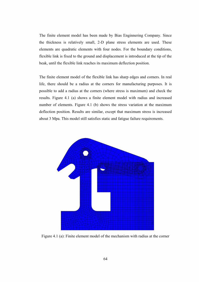
The finite element model of the flexible link has sharp edges and corners. In real
life, there should be a radius at the corners for manufacturing purposes. It is
possible to add a radius at the corners (where stress is maximum) and check the
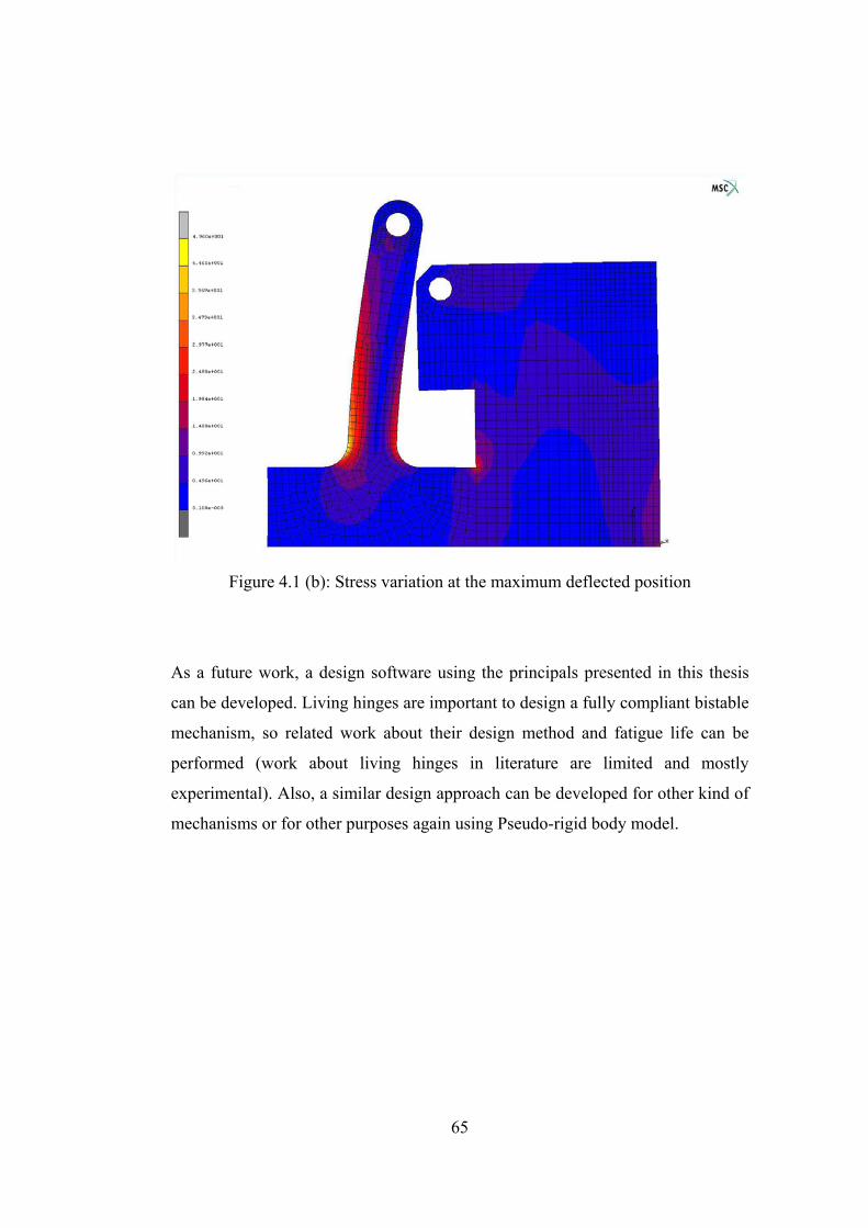
results. Figure 4.1 (a) shows a finite element model with radius and increased
number of elements. Figure 4.1 (b) shows the stress variation at the maximum
deflection position. Results are similar, except that maximum stress is increased
about 3 Mpa. This model still satisfies static and fatigue failure requirements.
Figure 4.1 (a): Finite element model of the mechanism with radius at the corner
65
Figure 4.1 (b): Stress variation at the maximum deflected position
As a future work, a design software using the principals presented in this thesis
can be developed. Living hinges are important to design a fully compliant bistable
mechanism, so related work about their design method and fatigue life can be
performed (work about living hinges in literature are limited and mostly
experimental). Also, a similar design approach can be developed for other kind of
mechanisms or for other purposes again using Pseudo-rigid body model.
66
REFERENCES
1. Frecker, Mary I., Canfield, Shawn, Methodology for Systematic Design of Compliant Mechanisms with Integrated Smart Materials.
2. Howell, Larry L., Compliant Mechanisms, John Wiley & Sons Inc., 2001 3. Jensen, Brian D., Identification of Macro and Micro Compliant
Mechanism Configurations Resulting In Bistable Behaviour, M.S., Brigham Young University, 1998
4. Jensen, Brian D., Howell, Larry L., Salmon, Linton G., Introduction Of Two-link, In-plane, Bistable Compliant MEMS, ASME Design Engineering Technical Conferences, September 13-16, 1998
5. Jensen, Brian D., Parkinson, Matthew B., Kurabayashi, Katsuo, Howell, Larry L., Baker, Michael S., Design Optimization Of A Fully Compliant Bistable Micro Mechanism, ASME International Mechanical Engineering Congress and Exposition, November 11-16, 2001
6. Jensen, Brian D., Howell, Larry L., Roach, Gregory M., Bistable Compliant Mechanism, United States Patent, Patent No: US 6,215,081 B1, 2001
7. Kota, Sridhar, Joo, Jinyong, Li Zhe, Rodgers, Steven M., Sniegowski, Jeff, Design of Compliant Mechanisms: Application to MEMS, Kluwer Academic Publishers, 2001
8. Opdahl, Patrick G., Jensen, Brian D., Howell, Larry L., An Investigation Into Compliant Bistable Mechanisms, ASME Design Engineering Technical Conferences, September 13-16, 1998
9. Parkinson, Matthew B., Jensen, Brian D., Roach, Gregory M., Optimization Based Design Of A Fully Compliant Bistable Micromechanism, ASME Design Engineering Technical Conferences, September 10-13, 2000
67
10. Shames, Irving H., Engineering Mechanics (3rd Edition), Prentice-Hall Inc., 1980
11. Shigley, J.Edward, Mechanical Engineering Design (First Metric Edition),
McGraw Hill, 1986 12. Sevak, N.M., McLarnen, C.W., Optimal Synthesis of Flexible Link
Mechanisms with Large Static Deflections, ASME Paper, 1974
13. Soylu, R., ME 301-Theory of Machines class notes, Middle East Technical University, 2000
14. Söylemez, E., Mechanisms (3rd Edition), Middle East Technical
University, Publication Number: 64, 1999 15. Söylemez, E., ME 431-Synthesis of Mechanisms class notes, Middle East
Technical University, 2001
16. Wittwer, Jonathan W., Predicting the Effects of Dimensional and Material Property Variations in Micro Compliant Mechanisms, M.S., Brigham Young University, 2001
17. Kota, Sridhar, Compliant Systems Design Laboratory, www.engin.umich.edu/labs/csdl/app.html, 2005 18. Flexsys Inc., Automotive Windshield Wiper, www.flxsys.com/wiper-blade_pic-proto.shtml, 2005
19. Howell, Larry L., Compliant Mechanisms Home Page at Byu, www.research.et.byu.edu/llhwww/, 2005 20. Pedersen, Claus B.W., Buhl, Thomas, Topology Optimization, www.topopt.dtu.dk/Theory1, 2005
68
21. MSC Software, ADAMS/Autoflex, www.mscsoftware.com/Products/Products_Detail.cfm?PI=423&S=91, 2005 22. Anantashuresh, G.K., The research Group of Anantashuresh, www.seas.upenn.edu/~gksuresh/mysoft.html, 2005 23. Quint Corporation, OPTISHAPE, www.quint.co.jp/eng/pro/ots/index.htm, 2005 24. Arcelik “Malbis” Material Database, 2005
25. Plastic Design Library Staff, Fatigue and Tribological Properties of
Plastics and Elastomers, 1995
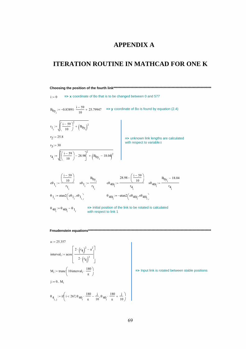
69
APPENDIX A
ITERATION ROUTINE IN MATHCAD FOR ONE K
θ4i j,if i 267< θ40i
180π
⋅j
10−, θ40i
180π
⋅j
10+,⎛⎜
⎝⎞⎠
:=
j 0 Mi..:=
=> Input link is rotated between stable positionsMi trunc 10intervali180π
⋅⎛⎜⎝
⎞⎠
:=
intervali acos2 r4i( )2⋅ a2−
2 r4i( )2⋅
⎡⎢⎢⎢⎣
⎤⎥⎥⎥⎦
:=
a 25.357:=
Freudenstein equations*********************************************************************************************
=> initial position of the link to be rotated is calculated with respect to link 1
θ40iθ40ii
θ1i−:=
θ40iiatan2 cθ40ii
sθ40ii,⎛
⎝⎞⎠
−:=θ1iatan2 cθ1i
sθ1i,⎛
⎝⎞⎠
:=
sθ40ii
B0yi18.04−
r4i
:=cθ40ii
28.98i 59−
10⎛⎜⎝
⎞⎠
−
r4i
:=sθ1i
B0yi
r1i
:=cθ1i
i 59−
10⎛⎜⎝
⎞⎠
r1i
:=
r4i
i 59−
10⎛⎜⎝
⎞⎠
28.98−⎡⎢⎣
⎤⎥⎦
2B0yi
18.04−( )2+:=
r3 30:=
=> unknown link lengths are calculated with respect to variable i
r2 25.8:=
r1i
i 59−
10⎛⎜⎝
⎞⎠
2B0yi( )2+:=
=> y coordinate of Bo is found by equation (2.4)B0yi0.83891−
i 59−
10⋅ 25.79947+:=
=> x coordinate of Bo that is to be changed between 0 and 577i 0:=
Choosing the position of the fourth link**************************************************************************
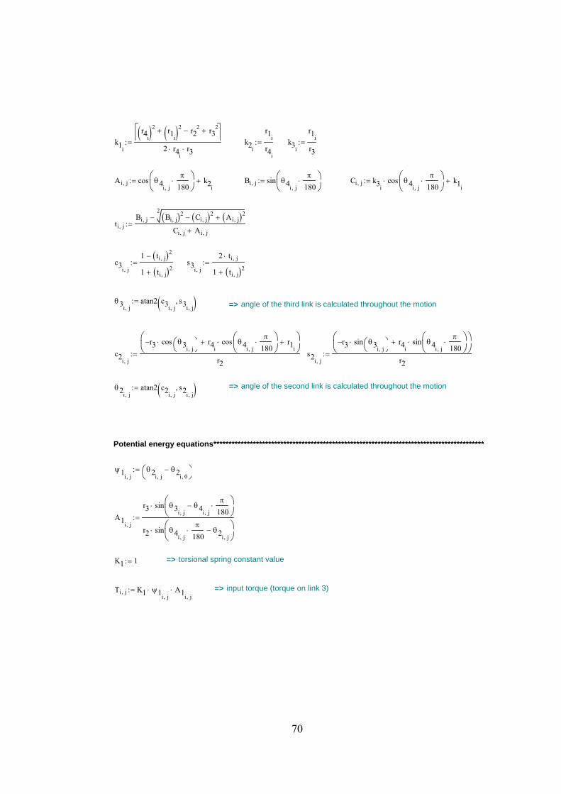
70
=> input torque (torque on link 3)Ti j, K1 ψ1i j,⋅ A1i j,
⋅:=
=> torsional spring constant valueK1 1:=
A1i j,
r3 sin θ3i j,θ4i j,
π
180⋅−⎛⎜
⎝⎞⎠
⋅
r2 sin θ4i j,
π
180⋅ θ2i j,
−⎛⎜⎝
⎞⎠
⋅
:=
ψ1i j,θ2i j,
θ2i 0,−⎛
⎝⎞⎠
:=
Potential energy equations*****************************************************************************************
=> angle of the second link is calculated throughout the motionθ2i j,atan2 c2i j,
s2i j,,( ):=
s2i j,
r3− sin θ3i j,⎛⎝
⎞⎠
⋅ r4isin θ4i j,
π
180⋅⎛⎜
⎝⎞⎠
⋅+⎛⎜⎝
⎞⎠
r2:=c2i j,
r3− cos θ3i j,⎛⎝
⎞⎠
⋅ r4icos θ4i j,
π
180⋅⎛⎜
⎝⎞⎠
⋅+ r1i+⎛⎜
⎝⎞⎠
r2:=
=> angle of the third link is calculated throughout the motionθ3i j,atan2 c3i j,
s3i j,,( ):=
s3i j,
2 ti j,⋅
1 ti j,( )2+:=c3i j,
1 ti j,( )2−
1 ti j,( )2+:=
ti j,Bi j,
2Bi j,( )2 Ci j,( )2− Ai j,( )2+−
Ci j, Ai j,+:=
Ci j, k3icos θ4i j,
π
180⋅⎛⎜
⎝⎞⎠
⋅ k1i+:=Bi j, sin θ4i j,
π
180⋅⎛⎜
⎝⎞⎠
:=Ai j, cos θ4i j,
π
180⋅⎛⎜
⎝⎞⎠
k2i+:=
k3i
r1i
r3:=k2i
r1i
r4i
:=k1i
r4i( )2 r1i( )2+ r22− r3
2+⎡⎣
⎤⎦
2 r4i⋅ r3⋅
:=
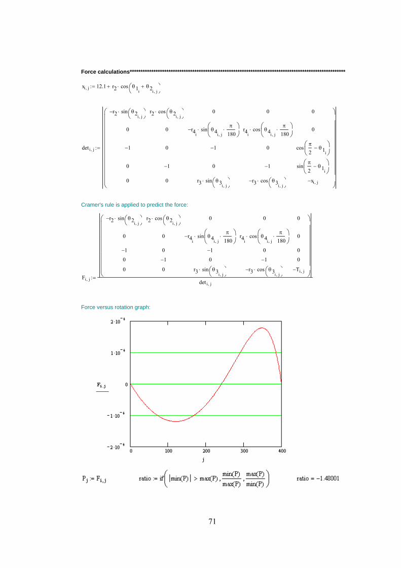
71
Force calculations****************************************************************************************************
xi j, 12.1 r2 cos θ1iθ2i j,
+⎛⎝
⎞⎠
⋅+:=
deti j,
r2− sin θ2i j,⎛⎝
⎞⎠
⋅
0
1−
0
0
r2 cos θ2i j,⎛⎝
⎞⎠
⋅
0
0
1−
0
0
r4i− sin θ4i j,
π
180⋅⎛⎜
⎝⎞⎠
⋅
1−
0
r3 sin θ3i j,⎛⎝
⎞⎠
⋅
0
r4icos θ4i j,
π
180⋅⎛⎜
⎝⎞⎠
⋅
0
1−
r3− cos θ3i j,⎛⎝
⎞⎠
⋅
0
0
cosπ
2θ1i
−⎛⎜⎝
⎞⎠
sinπ
2θ1i
−⎛⎜⎝
⎞⎠
xi j,−
⎛⎜⎜⎜⎜⎜⎜⎜⎜⎜⎜⎝
⎞
⎟⎟⎟⎟⎟⎟⎟⎟
⎠
:=
Cramer's rule is applied to predict the force:
Fi j,
r2− sin θ2i j,⎛⎝
⎞⎠
⋅
0
1−
0
0
r2 cos θ2i j,⎛⎝
⎞⎠
⋅
0
0
1−
0
0
r4i− sin θ4i j,
π
180⋅⎛⎜
⎝⎞⎠
⋅
1−
0
r3 sin θ3i j,⎛⎝
⎞⎠
⋅
0
r4icos θ4i j,
π
180⋅⎛⎜
⎝⎞⎠
⋅
0
1−
r3− cos θ3i j,⎛⎝
⎞⎠
⋅
0
0
0
0
Ti j,−
⎛⎜⎜⎜⎜⎜⎜⎜⎜⎝
⎞⎟⎟⎟⎟⎟⎟
⎠det i j,
:=
Force versus rotation graph:

72
APPENDIX B
ITERATION ROUTINE IN MATHCAD FOR SEVERAL K
θ4i j,if i 267< θ40i
180π
⋅j
10−, θ40i
180π
⋅j
10+,⎛⎜
⎝⎞⎠
:=
j 0 Mi..:=
=> Input link is rotated between stable positionsMi trunc 10intervali180π
⋅⎛⎜⎝
⎞⎠
:=
intervali acos2 r4i( )2⋅ a2−
2 r4i( )2⋅
⎡⎢⎢⎢⎣
⎤⎥⎥⎥⎦
:=
a 25.357:=
Freudenstein equations*********************************************************************************************
=> initial position of the link to be rotated is calculated with respect to link 1
θ40iθ40ii
θ1i−:=
θ40iiatan2 cθ40ii
sθ40ii,⎛
⎝⎞⎠
−:=θ1iatan2 cθ1i
sθ1i,⎛
⎝⎞⎠
:=
sθ40ii
B0yi18.04−
r4i
:=cθ40ii
25.01i 99−
10⎛⎜⎝
⎞⎠
−
r4i
:=sθ1i
B0yi
r1i
:=cθ1i
i 99−
10⎛⎜⎝
⎞⎠
r1i
:=
r4i
i 99−
10⎛⎜⎝
⎞⎠
25.01−⎡⎢⎣
⎤⎥⎦
2B0yi
18.04−( )2+:=
r3 23.7:==> unknown link lengths are calculated with respect to variable i
r2 17.95:=
r1i
i 99−
10⎛⎜⎝
⎞⎠
2B0yi( )2+:=
=> y coordinate of Bo is found by equation (2.4)B0yi0.8391−
i 99−
10⋅ 22.4676+:=
=> x coordinate of Bo that is to be changed between 0 and 577i 53:=
Choosing the position of the fourth link**************************************************************************

73
=> torsional spring constant valuesK4 0:=K3 36.68:=K2 0:=K1 1:=
A2i j,
r3 sin θ3i j,θ2i j,
−⎛⎝
⎞⎠
⋅
r4isin θ4i j,
π
180⋅ θ2i j,
−⎛⎜⎝
⎞⎠
⋅
:=A1i j,
r3 sin θ3i j,θ4i j,
π
180⋅−⎛⎜
⎝⎞⎠
⋅
r2 sin θ4i j,
π
180⋅ θ2i j,
−⎛⎜⎝
⎞⎠
⋅
:=
ψ3i j,θ4i j,
θ4i 0,−⎛
⎝⎞⎠
π
180⋅ θ3i j,
θ3i 0,−⎛
⎝⎞⎠
−:=ψ4i j,θ4i j,
θ4i 0,−⎛
⎝⎞⎠
π
180⋅:=
ψ2i j,θ2i j,
θ2i 0,−⎛
⎝⎞⎠
θ3i j,θ3i 0,
−⎛⎝
⎞⎠
−:=ψ1i j,θ2i j,
θ2i 0,−⎛
⎝⎞⎠
:=
Potential energy equations*****************************************************************************************
=> angle of the second link is calculated throughout the motionθ2i j,atan2 c2i j,
s2i j,,( ):=
s2i j,
r3− sin θ3i j,⎛⎝
⎞⎠
⋅ r4isin θ4i j,
π
180⋅⎛⎜
⎝⎞⎠
⋅+⎛⎜⎝
⎞⎠
r2:=c2i j,
r3− cos θ3i j,⎛⎝
⎞⎠
⋅ r4icos θ4i j,
π
180⋅⎛⎜
⎝⎞⎠
⋅+ r1i+⎛⎜
⎝⎞⎠
r2:=
=> angle of the third link is calculated throughout the motionθ3i j,atan2 c3i j,
s3i j,,( ):=
s3i j,
2 ti j,⋅
1 ti j,( )2+:=c3i j,
1 ti j,( )2−
1 ti j,( )2+:=
ti j,Bi j,
2Bi j,( )2 Ci j,( )2− Ai j,( )2+−
Ci j, Ai j,+:=
Ci j, k3icos θ4i j,
π
180⋅⎛⎜
⎝⎞⎠
⋅ k1i+:=Bi j, sin θ4i j,
π
180⋅⎛⎜
⎝⎞⎠
:=Ai j, cos θ4i j,
π
180⋅⎛⎜
⎝⎞⎠
k2i+:=
k3i
r1i
r3:=k2i
r1i
r4i
:=k1i
r4i( )2 r1i( )2+ r22− r3
2+⎡⎣
⎤⎦
2 r4i⋅ r3⋅
:=
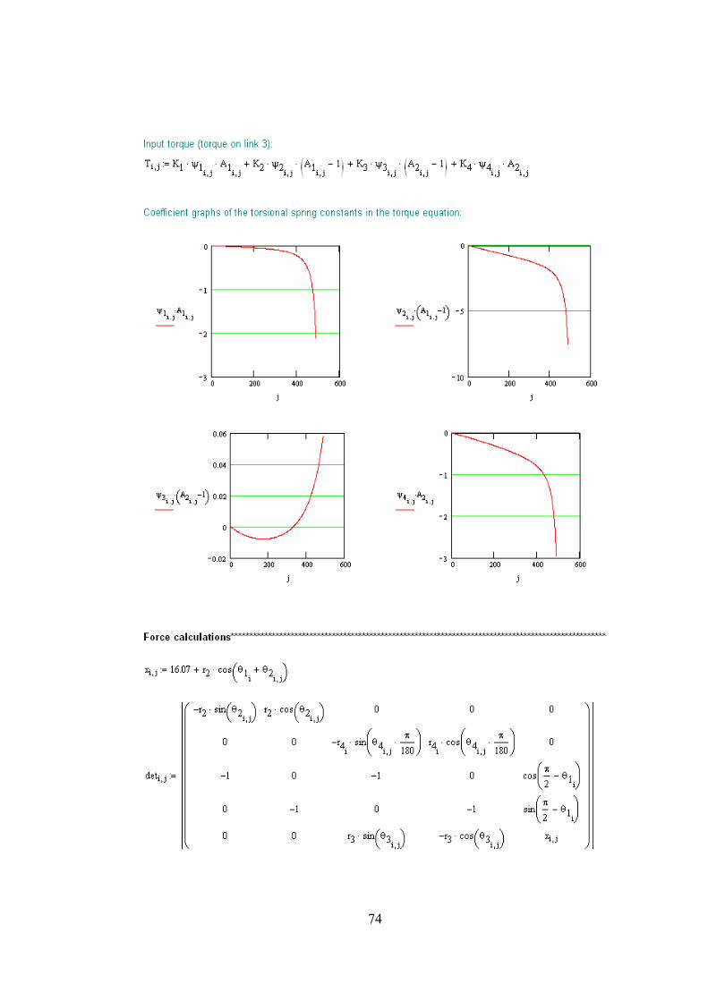
74
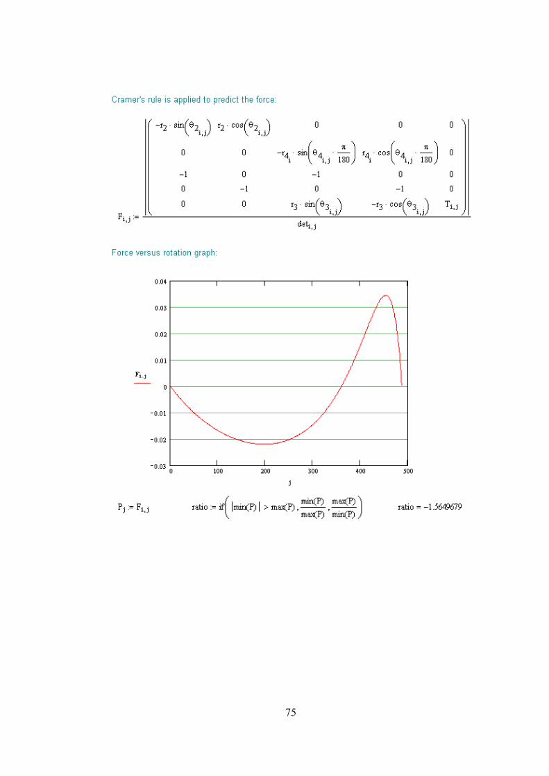
75

76
APPENDIX C
MECHANICAL PROPERTIES OF SOME POLYMERS
Table C.1: Mechanical properties of some polymers [2], [11], [24]
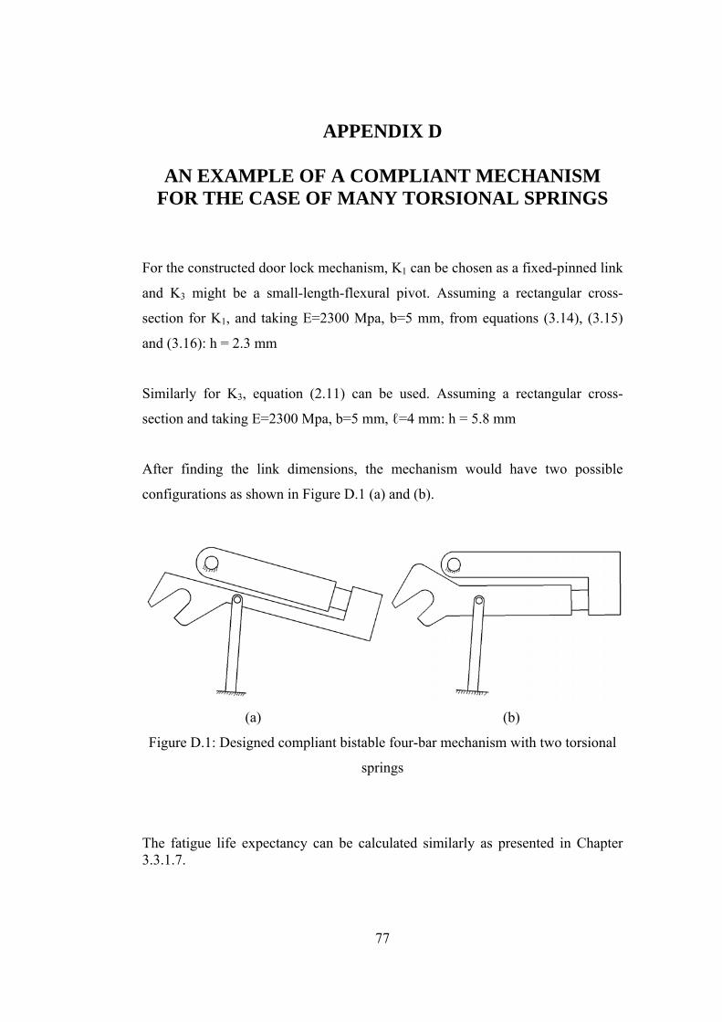
77
APPENDIX D
AN EXAMPLE OF A COMPLIANT MECHANISM FOR THE CASE OF MANY TORSIONAL SPRINGS
For the constructed door lock mechanism, K1 can be chosen as a fixed-pinned link
and K3 might be a small-length-flexural pivot. Assuming a rectangular cross-
section for K1, and taking E=2300 Mpa, b=5 mm, from equations (3.14), (3.15)
and (3.16): h = 2.3 mm
Similarly for K3, equation (2.11) can be used. Assuming a rectangular cross-
section and taking E=2300 Mpa, b=5 mm, ℓ=4 mm: h = 5.8 mm
After finding the link dimensions, the mechanism would have two possible
configurations as shown in Figure D.1 (a) and (b).
(a) (b)
Figure D.1: Designed compliant bistable four-bar mechanism with two torsional
springs
The fatigue life expectancy can be calculated similarly as presented in Chapter 3.3.1.7.