Synthesis of Boron Nitride Coated Silica Filler for ...
6
Synthesis of Boron Nitride Coated Silica Filler for Preparing Thermally Conductive Epoxy Composites Jiaxiong Li, Yanjuan Ren, Dong An, Kyoung-sik Moon and Ching-ping Wong School of Materials Science and Engineering, Georgia Institute of Technology, Atlanta, GA, USA [email protected] Abstract— Increasing power density in the modern electronics with continuous miniaturization and rapid growth in functionality demands fast heat removal capability of the package from the chip. Traditional encapsulant materials such as epoxy molding compounds or underfills are seen as poor thermal conductor due to the low intrinsic thermal conductivity of the fused silica fillers (~1 W/mK) extensively used in formulating these epoxy encapsulants. Boron nitride (BN) possesses extraordinarily high thermal conductivity (~400 W/mK in plane) but its 2-D platelet shape limits the loading level due to the rheological issues. In this work, the BN coated silica (BN@SiO2) fillers are synthesized through silane assisted assembly method. The chemical modification on the filler interface chemistry and the morphology of the synthesized BN@SiO2 is discussed in detail. A significantly reduced viscosity at various shear rates demonstrates the better flowability of epoxy loaded with BN@SiO2 fillers compared to those directly mixed with BN and SiO2 fillers, indicating the potential of further increase of BN loading level. Moreover, the much-improved thermal conductivity in these composites (~0.7 W/mK at 30 wt% loading) suggests that the as synthesized BN@SiO2 could be promising candidate to prepare highly thermally conductive epoxy encapsulants in order to effectively dissipate the heat generated from high performance chips. Keywords-Epoxy composites; Encapsulant; Boron Nitride; Thermal Conductivity I. INTRODUCTION Growing needs in fast heat spreading and heat removal capabilities of the packaging components have been seen in the industry to guarantee optimum performance and long-term reliability of the today’s highly integrated IC packages with ever increasing functionality and power densities [1]. In addition to the thermal management structural design based on heat sink, thermal card or vapor chamber designs, the intrinsic thermal properties of the encapsulant materials such as the underfills or epoxy molding compounds (EMC) play vital roles in the entire thermal design scheme in flip chip and fan out wafer level packages, where high thermal conductivity of these materials is highly desirable as they provide alternative heat dissipation paths to cool the chip and reduce the thermal stress generated at interfaces of the package [2, 3]. The underfill materials mainly serve to distribute the shear stress generated inside the C4 (control collapse chip connection) joints in flip-chip packages during thermal cycling [4], while EMC is normally the outermost protection layer over the die [5]. The epoxy based encapsulant materials offer superior adhesion, good electrical insulation properties, good resistance to chemicals, at a much lower cost compared to the heavy and expensive ceramic packages, therefore has been adopted as the standard technology in most advanced packaging applications. These epoxy composites are heavily loaded with inorganic fillers such as fused silica (typically 80-90 wt% in EMC and 60 wt% in underfill, having CTE of ~ 0.5 ppm/K) in order to match their CTE with silicon chips, substrates or solder balls therefore reducing thermal stress during cycling. Unfortunately, the amorphous nature of the fused silica renders rather poor thermal conductivity (1-2 W/mK) since the phonon (or vibrational wave), the major thermal carrier in insulating materials, is reluctant to transport through the irregular atomic structures. This low intrinsic thermal conductivity of amorphous silica limits the composite thermal conductivity of epoxy compounds to ~1 W/mK level which is far from satisfaction for many high performance or high-power applications. As a traditional approach, replacing the silica with other highly thermally conductive while electrically insulative ceramic fillers such as alumina (Al2O3) to produce higher thermally conductive epoxy composites has made commercially available for many high-end products. However, the highest value achieved in these alumina filled epoxies is around 5 W/mK, while the high dielectric constant of the alumina fillers (~10) makes it undesirable in certain applications involving high frequency operations. Other than alumina, aluminum nitride (AlN), silicon carbide (SiC), silicon nitride (Si3N4) and boron nitride (BN) [6] are popular fillers offering much improved thermal conductivity than silica. A table (Table I) is compiled to compare the physical, thermal and electrical properties of these ceramic fillers. Among them, hexagonal BN (h-BN) is known for its intrinsic ultra-high thermal conductivity, preferred electrical properties including high breakdown voltage and low dielectric constant [7, 8]. One limitation of the h-BN powder, however, greatly constrains the further utilization of them in formulating epoxy composites. The unique 2-D platelet shape and low-density nature of h-BN particles produces many difficulties in processing their polymer composites. The undesired flowability of the filler-resin mix originated form the large contact area between 2-D fillers greatly impedes the further increase of filler loading level. 2019 2020 IEEE 70th Electronic Components and Technology Conference (ECTC) 2377-5726/20/$31.00 ©2020 IEEE DOI 10.1109/ECTC32862.2020.00314 Authorized licensed use limited to: Georgia Institute of Technology. Downloaded on March 16,2021 at 18:39:02 UTC from IEEE Xplore. Restrictions apply.
Transcript of Synthesis of Boron Nitride Coated Silica Filler for ...

Synthesis of Boron Nitride Coated Silica Filler for Preparing Thermally Conductive Epoxy Composites
Jiaxiong Li, Yanjuan Ren, Dong An, Kyoung-sik Moon and Ching-ping WongSchool of Materials Science and Engineering, Georgia Institute of Technology, Atlanta, GA, USA
Abstract— Increasing power density in the modern electronics with continuous miniaturization and rapid growth in functionality demands fast heat removalcapability of the package from the chip. Traditionalencapsulant materials such as epoxy molding compounds or underfills are seen as poor thermal conductor due to the low intrinsic thermal conductivity of the fused silica fillers (~1 W/mK) extensively used in formulating these epoxy encapsulants. Boron nitride (BN) possesses extraordinarilyhigh thermal conductivity (~400 W/mK in plane) but its 2-Dplatelet shape limits the loading level due to the rheological issues. In this work, the BN coated silica (BN@SiO2) fillers are synthesized through silane assisted assembly method.The chemical modification on the filler interface chemistryand the morphology of the synthesized BN@SiO2 isdiscussed in detail. A significantly reduced viscosity atvarious shear rates demonstrates the better flowability of epoxy loaded with BN@SiO2 fillers compared to thosedirectly mixed with BN and SiO2 fillers, indicating thepotential of further increase of BN loading level. Moreover, the much-improved thermal conductivity in these composites (~0.7 W/mK at 30 wt% loading) suggests that the as synthesized BN@SiO2 could be promising candidate to prepare highly thermally conductive epoxy encapsulants in order to effectively dissipate the heat generated from high performance chips.
Keywords-Epoxy composites; Encapsulant; Boron Nitride; Thermal Conductivity
I. INTRODUCTION
Growing needs in fast heat spreading and heat removalcapabilities of the packaging components have been seen in the industry to guarantee optimum performance and long-term reliability of the today’s highly integrated ICpackages with ever increasing functionality and power densities [1]. In addition to the thermal management structural design based on heat sink, thermal card or vapor chamber designs, the intrinsic thermal properties of theencapsulant materials such as the underfills or epoxy molding compounds (EMC) play vital roles in the entirethermal design scheme in flip chip and fan out wafer level packages, where high thermal conductivity of these materials is highly desirable as they provide alternative heat dissipation paths to cool the chip and reduce the thermal stress generated at interfaces of the package [2, 3].
The underfill materials mainly serve to distribute the shear stress generated inside the C4 (control collapse chipconnection) joints in flip-chip packages during thermal
cycling [4], while EMC is normally the outermost protection layer over the die [5]. The epoxy basedencapsulant materials offer superior adhesion, goodelectrical insulation properties, good resistance to chemicals, at a much lower cost compared to the heavyand expensive ceramic packages, therefore has beenadopted as the standard technology in most advanced packaging applications. These epoxy composites areheavily loaded with inorganic fillers such as fused silica (typically 80-90 wt% in EMC and 60 wt% in underfill,having CTE of ~ 0.5 ppm/K) in order to match their CTE with silicon chips, substrates or solder balls therefore reducing thermal stress during cycling. Unfortunately, the amorphous nature of the fused silica renders rather poor thermal conductivity (1-2 W/mK) since the phonon (or vibrational wave), the major thermal carrier in insulating materials, is reluctant to transport through the irregularatomic structures. This low intrinsic thermal conductivity of amorphous silica limits the composite thermal conductivity of epoxy compounds to ~1 W/mK level which is far from satisfaction for many high performance or high-power applications.
As a traditional approach, replacing the silica with other highly thermally conductive while electrically insulative ceramic fillers such as alumina (Al2O3) to produce higher thermally conductive epoxy compositeshas made commercially available for many high-end products. However, the highest value achieved in these alumina filled epoxies is around 5 W/mK, while the high dielectric constant of the alumina fillers (~10) makes it undesirable in certain applications involving high frequency operations. Other than alumina, aluminum nitride (AlN), silicon carbide (SiC), silicon nitride (Si3N4)and boron nitride (BN) [6] are popular fillers offering much improved thermal conductivity than silica. A table(Table I) is compiled to compare the physical, thermal and electrical properties of these ceramic fillers. Among them,hexagonal BN (h-BN) is known for its intrinsic ultra-high thermal conductivity, preferred electrical properties including high breakdown voltage and low dielectric constant [7, 8]. One limitation of the h-BN powder,however, greatly constrains the further utilization of them in formulating epoxy composites. The unique 2-D platelet shape and low-density nature of h-BN particles produces many difficulties in processing their polymer composites.The undesired flowability of the filler-resin mix originated form the large contact area between 2-D fillers greatlyimpedes the further increase of filler loading level.
2019
2020 IEEE 70th Electronic Components and Technology Conference (ECTC)
2377-5726/20/$31.00 ©2020 IEEEDOI 10.1109/ECTC32862.2020.00314
Authorized licensed use limited to: Georgia Institute of Technology. Downloaded on March 16,2021 at 18:39:02 UTC from IEEE Xplore. Restrictions apply.

TABLE I COMPARISON OF THERMAL, ELECTRICAL AND PHYSICAL PROPERTIES OF VARIOUS COMMON CERAMIC FILLERS WITH HIGH
THEMRAL CONDCUTIVITY
Thermalconductivity(W/mK)
Density(g/cm3) Dielectric Constant
CTE (ppm/K)
Al2O3 30 3.95 10 8.4
AlN 140-180 3.26 9 4.5
SiC 120 3.1 9 4
BN 400 in plane 1.9 4 38 in plane
Si3N4 30 3.29 9.5 3.3
In order to obtain processable h-BN filled epoxy with even higher filler loading, spherical shape BN filler made by h-BN platelet agglomerates is highly desirable from arheological standpoint [9]. Furthermore, the agglomeratecan make use of the tremendously high in-plane thermal conductivity of h-BN and make it isotropically conductive.Synthesizing spherical h-BN agglomerates has beenactively pursued in previous researches and commercial products in series such as Boron Nitride Cooling Fillersfrom 3MTM or PolarTherm* Boron Nitride Powder fromMomentiveTM. These BN agglomerates are mainly produced by using binders to glue the BN platelets duringsolution processes and later burning out the binders through high temperature treatment [10]. The inner space of these agglomerates is therefore left empty, which on the one hand may lead to void formation during epoxy curing,on the other hand is unfavorable for the CTE control purpose since the silica loading is reduced. Anotherimportant limitation is that the major h-BN agglomerateproducts share a rather large size mostly over 50 μm that impedes their application in fine-pitch packaging.
To further improve the performance of the h-BN agglomerates mentioned above, we propose to innovateBN coated silica (BN@SiO2) hybrid filler design. In this scheme, the spherical h-BN shape is made possible by assembly of the BN platelets on spherical silica particles as templates, providing good flowability when mixed in resins while remaining silica as the main filler in the system. A fast-thermal runaway is constructed after curing on the surfaces of silica particles. The synthesis route, morphology studies, rheology properties and thermal conductivity of the epoxy resin filled with different weight percent of BN@SiO2 filler compared to the control setwith direct co-mixing of same loading of BN and SiO2filler is presented in this paper. The significantly reduced mix viscosity of BN@SiO2 filled epoxy suggests that the method proposed here being an attracting way to further increase BN loading in epoxy-silica based composite material for producing highly thermally conductiveencapsulant for high performance packaging applications.
II. EXPERIMENTAL
A. MaterialsHexagonal BN platelets with size of ~1 μm (NX1)
were obtained from MomentiveTM Performance Materials. Silica particles with diameter of 4.5±0.5 μm (LE-05S)were obtained from Nippon Chemical Industrial Co., Ltd.(3-Aminopropyl) triethoxysilane (99%, APTES) and (3-Glycidyloxypropyl) trimethoxysilane ( 98%, GPTMS)were purchased from Aldrich and used as received.ERL4206 resin was obtained from Union Carbide Co.. And the Lindride 52D anhydride hardener was obtained from Lindau Chemicals, Inc.B. Method
In order to functionalize BN with hydroxyl (-OH)groups, the BN particles were ball milled with sucrose for 24 hrs, rinsed with DI water and collected through filtration. Then, -OH grafted BN were treated with hydrolyzed APTES for grafting amine (-NH2) groups. The silane grafting reaction was carried in ethanol environment at 80 ºC and stirred for 4 hrs. SiO2 particles were treated with GPTMS in a similar manner. After the silane treated BN and SiO2 being rinsed, centrifuged for several cycles, the two kinds of dried particles were stirred in toluene at 120 ºC to allow BN assembly on SiO2through the amine-epoxide reaction. The reaction products were collected as BN@SiO2 particles and dried before compounding. The epoxy composites were prepared by mixing the above-mentioned BN@SiO2particles with ERL4206 resin and Lindride 52D hardener(1:1 weight ratio) at desired loading level, while the control samples were made by directly mixing epoxy with the untreated BN and SiO2 fillers at the same amount. All the epoxy composites were cured at 150 ºC for 1 hr, 200 ºC for 1 hr and post-cured at 220 ºC for 1 hr.
C. CharacteriazationScanning Electron Microscope (SEM) pictures of the
particles and fracture surface of composites samples were taken by Hitachi SU8230 FE-SEM. Fourier-transform infrared spectroscopy (FTIR) was done using Thermo Scientific Nicolet iS5 FT-IR spectrometer in diamond ATR mode to track the chemical structure change of BN after modification. X-ray photoelectron spectroscopy (XPS) was done with Thermo Scientific K-Alpha XPS to analyze the surface chemistry of BN after chemicaltreatment. Viscosity of the epoxy mixture with fillers was obtained from TA Instrument Discovery HR-2 Rheometerusing parallel plate configuration. Thermal conductivity of the composite was calculated from the product of thermal diffusivity, specific heat and density. Thermal diffusivity of the sample was measured by Netzsch LFA 467 Hyperflash at 25 ºC, the specific heat by TA Instrument DSC Q2000 and the density by Archimedesmethod.
2020
Authorized licensed use limited to: Georgia Institute of Technology. Downloaded on March 16,2021 at 18:39:02 UTC from IEEE Xplore. Restrictions apply.
III. REUSLTS AND DISCUSSION
A. Cheracterzation of surface treated BN particlesHexagonal BN particles or graphitic BN are the most
stable form of h-BN and share a similar layered structurewith graphite. The chemically inert nature of h-BN particles due to lack of surface reactive groups often times limits their further chemical modification of surface treatment. The grafting of -OH groups is a common approach to functionalize BN particles thanks to the versatile chemistry of them in later modifications.
Various ways were developed over the years to introduce -OH groups on BN, including sonication, basetreatment and ball-milling methods or the combination of these. In this work the ball-milling method with sucrose as -OH source is selected to modify the h-BN particlesaccording to a previously reported method [11]. The milling inputs intense mechanical energy and assists the exfoliation of BN platelets, reducing their size and creatingsurface defects to which the -OH rich sucrose transfers the -OH groups. The effects of ball milling on h-BN morphology is shown in Fig. 1. A smaller particle size isanticipated and captured in Fig. 1(b) compared to Fig.1(a). The effective reduction of particles sizes is beneficial for the assembly process of the BN particles on SiO2 due to the fact larger covering area is permitted.g g
Fig. 1. SEM images of (a,c) raw h-BN particles and (b,d) ball-milled h-BN particle
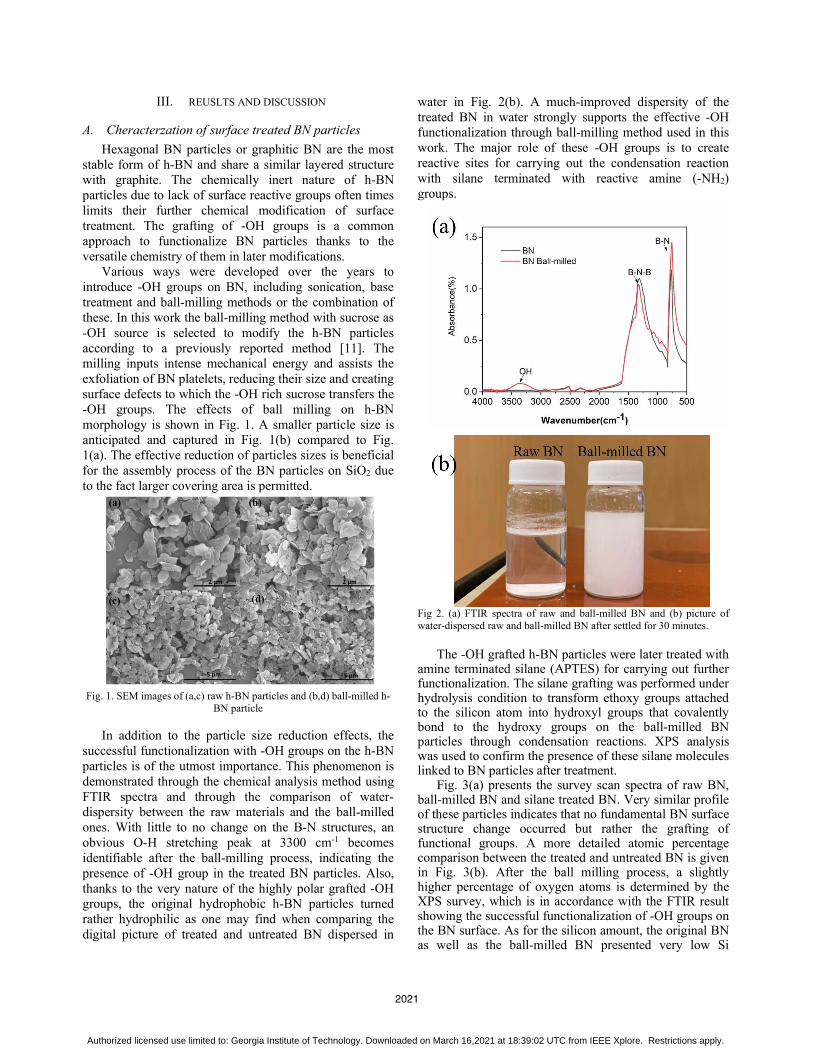
In addition to the particle size reduction effects, the successful functionalization with -OH groups on the h-BN particles is of the utmost importance. This phenomenon is demonstrated through the chemical analysis method using FTIR spectra and through the comparison of water-dispersity between the raw materials and the ball-milled ones. With little to no change on the B-N structures, anobvious O-H stretching peak at 3300 cm-1 becomesidentifiable after the ball-milling process, indicating the presence of -OH group in the treated BN particles. Also,thanks to the very nature of the highly polar grafted -OH groups, the original hydrophobic h-BN particles turned rather hydrophilic as one may find when comparing thedigital picture of treated and untreated BN dispersed in
water in Fig. 2(b). A much-improved dispersity of the treated BN in water strongly supports the effective -OHfunctionalization through ball-milling method used in this work. The major role of these -OH groups is to createreactive sites for carrying out the condensation reaction with silane terminated with reactive amine (-NH2)groups.g p
Fig 2. (a) FTIR spectra of raw and ball-milled BN and (b) picture ofwater-dispersed raw and ball-milled BN after settled for 30 minutes.
The -OH grafted h-BN particles were later treated with amine terminated silane (APTES) for carrying out further functionalization. The silane grafting was performed under hydrolysis condition to transform ethoxy groups attached to the silicon atom into hydroxyl groups that covalently bond to the hydroxy groups on the ball-milled BN particles through condensation reactions. XPS analysis was used to confirm the presence of these silane molecules linked to BN particles after treatment.
Fig. 3(a) presents the survey scan spectra of raw BN, ball-milled BN and silane treated BN. Very similar profile of these particles indicates that no fundamental BN surface structure change occurred but rather the grafting of functional groups. A more detailed atomic percentage comparison between the treated and untreated BN is given in Fig. 3(b). After the ball milling process, a slightlyhigher percentage of oxygen atoms is determined by the XPS survey, which is in accordance with the FTIR result showing the successful functionalization of -OH groups on the BN surface. As for the silicon amount, the original BNas well as the ball-milled BN presented very low Si
2021
Authorized licensed use limited to: Georgia Institute of Technology. Downloaded on March 16,2021 at 18:39:02 UTC from IEEE Xplore. Restrictions apply.

percentage in the sample, mainly due to the impurities. A significant rise of Si in the silane treated BN particles thatnearly trippled sufficiently supports that the silane being bonded to the BN particles. Also, since the silane used here contains amino groups at the chain end, we noticed the slightly increase of nitrogen percentage in these silane treated Bn as well. A more detailed look of the Si presented in the silane treated BN is given in Fig. 3(c)showing the Si 2p scan. A peak binding energy of ~ 103 eV implies the organic silicon nature of the bonded silanemolecules rather than that from other sorts of contaminants.
Fig 3. (a) XPS survey scan of raw BN, ball-milled BN and silane treated BN; (b) N, C, O and Si atomic percentage of raw BN, ball-milled BN and silane treated BN extracted from survey scan; (c) Si 2p scan of
silane treated BN.
B. Surface morphology of BN@SiO2 particlesAfter confirming the grafting of -NH2 groups to the
edge of BN particles, the assembly of amine functionalized BN on silica particles were carried out through the amine-epoxy reaction, where these silica particles were pre-treated with epoxide terminated silanes. The morphology of the BN@SiO2 synthesized thereof is shown in Fig.4(a) and (b). Through the control of materials formulation as well as the reaction conditions, the BN@SiO2 structure was realized. 2-D shaped BN platelets were found decorating on the spherical SiO2 templates through the covalent bonding, and a designed BN to SiO2 ratio guaranteed the conductive network formation via BN platelets contacting with each other on the surface of SiO2,as is demonstrated in the magnified SEM picture in Fig.4(b). Still, multilayer of BN stacking could be noticed giving an irregular shape of the hybrid filler structure, nevertheless the overall spherical shape BN outer shell is obtained using the template method.g p
Fig 4. SEM picture of synthesized BN@SiO2 particles under (a)10,000 and (b) 20,000 magnification
The 3-D nature of the above-mentioned BN@SiO2hybrid filler structure was believed to significantly reduce the viscosity of filler-epoxy mixture, therefore benefiting the further increase of BN loading level. However, due care must be taken in evaluating the processing ofcomposite material since it is crucial to identify whether the BN coating will still be remained after the vigorousblending process where the high shear forces are applied on the hybrid fillers. In order to investigate this intriguing issue, the SEM pictures of the composite materials after loading same level of the BN@SiO2 hybrid filler as well asthat made through directly mixing BN and SiO2 fillers into epoxy resin was compared in Fig. 5(a) and (b),respectively. The very distinguished surface morphologies between the two different types of the filler was found. In the composite consists of BN@SiO2 filler, the blistering surface exposing the coherent filler-polymer interface was
2022
Authorized licensed use limited to: Georgia Institute of Technology. Downloaded on March 16,2021 at 18:39:02 UTC from IEEE Xplore. Restrictions apply.

depicted, suggesting the strong filler-polymer interaction. On top of that, the light-colored flakes attached to the SiO2particles with a certain content of self-aggregation are believed to be the BN platelets remained on the silica surface after composite mixing and epoxy curing. On the other hand, the direct co-mixed BN and SiO2 fillers resulted in quite smooth surface finished after rupture, and the BN particles became impossible to recognize. It is concluded that a large portion of these covalently bonded BN remained on the SiO2 surfaces. The silane grafting the the C-N bond formed from amine-epoxide reaction provides strong adhesion between the BN and SiO2 fillers,as such the spherical geometry of the BN agglomerates could be maintained during high shear processing as wellas the beneficial the low viscosity. Moreover, the configuration of BN@SiO2 being preserved after compositing is vital since it restricts the possible phase separation of BN fillers and SiO2 fillers. The reasonabledistribution of the more conductive BN part by coating them on the SiO2 carriers supports the conductive network formation in the composites with higher loading levels.p g g
Fig 5. SEM picture of a silica particle at the fractured surface of epoxycomposites loaded with (a) BN@SiO2 filler and (b) directly-mixed
BN+SiO2 fillerRheological properteis of the epoxy-BN@SiO2 mixtures
In order to demonstrate the effects of sphericalBN@SiO2 in reducing the flow viscosity of epoxycomposites during processing, the rheology studies wereconducted in the epoxy mixes with an emphasis on the shape effects. The epoxy monomer and hardeners were mixed with different weight percent of BN@SiO2 fillers, while the control samples were loaded with same amount of co-mixed BN and SiO2 particles. Their viscosities at various shear rates ranging from 1-1000 1/s is shown inFig. 6. The extremely low viscosity of pure epoxy sample was originated from the low aromaticity nature of cycloaliphatic epoxy. An increase viscosity was associated with the increasing the filler loading level due to the
incorporation of heterogeneous particles and creation ofmany interfaces. All formulations including the pure epoxy reference presented shear thinning behavior, that is,lowered shear viscosity with increased shear rate.Especially in the higher loading samples, the shear thinning properties of the samples became even more obvious. For example, in the 30 wt% filler loaded composites, the over 10 Pa*s viscosity at shear rate of 11/s significantly reduced to less than 1 Pa*s at 1000 1/s shear rate. This fact suggests that the high shear processing would be suitable in reducing mixture viscosity and produce well dispersed epoxy composite. Whencomparing the mixture viscosity of the two different types of composites with same filler loading, it is not hard to find out that all BN@SiO2 filled systems presented lower shear viscosity than the co-mixed ones. Especially, the 20 wt% loaded BN@SiO2 sample was found only slightly more viscos than the 10 wt% filled BN+SiO2 sample. These facts strongly support the idea in this work ofreducing composite viscosity via creating spherical BN@SiO2 fillers. Therefore, the further increase of BNfiller loading level with the novel synthesized filler technology could be anticipated in formulating the highly thermally conductive epoxy composites.
Fig 6. Viscosity of epoxy, epoxy loaded with different percentage of BN@SiO2 fillers and BN+SiO2 hybrid fillers.Thermal condcutivity of
the epoxy-BN@SiO2 composites
The thermal conductivity of epoxy composites loaded with the synthesized BN@SiO2 and the control sets that are directly mixed with BN and SiO2 hybrid fillers were measured by laser flash technique. Fig. 7 presents the measured thermal conductivity of the epoxy composites with up to 30 wt% loading. In both cases, a great improvement in thermal conductivity of the loaded sample was found after the loading of ceramic fillers compared tothe intrinsic epoxy value of merely over 0.1 W/mK. 10wt% of the hybrid fillers were able to boost the compositethermal conductivity to ~ 0.5 W/mK level, which is of 400% increase to that of the pure epoxy. Generally, the composite thermal conductivity followed the rule of mixture when further increasing the filler loading level. On top of that, interestingly, all the BN@SiO2 filled epoxies
2023
Authorized licensed use limited to: Georgia Institute of Technology. Downloaded on March 16,2021 at 18:39:02 UTC from IEEE Xplore. Restrictions apply.
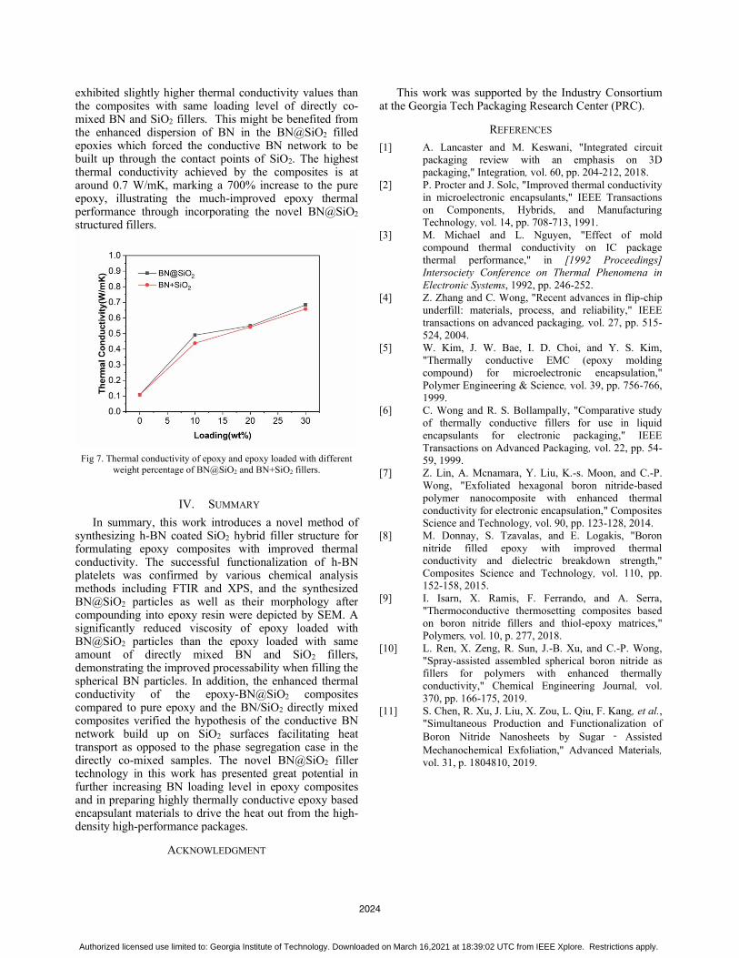
exhibited slightly higher thermal conductivity values than the composites with same loading level of directly co-mixed BN and SiO2 fillers. This might be benefited fromthe enhanced dispersion of BN in the BN@SiO2 filledepoxies which forced the conductive BN network to be built up through the contact points of SiO2. The highest thermal conductivity achieved by the composites is at around 0.7 W/mK, marking a 700% increase to the pure epoxy, illustrating the much-improved epoxy thermal performance through incorporating the novel BN@SiO2structured fillers.
Fig 7. Thermal conductivity of epoxy and epoxy loaded with different weight percentage of BN@SiO2 and BN+SiO2 fillers.
IV. SUMMARY
In summary, this work introduces a novel method ofsynthesizing h-BN coated SiO2 hybrid filler structure for formulating epoxy composites with improved thermal conductivity. The successful functionalization of h-BN platelets was confirmed by various chemical analysis methods including FTIR and XPS, and the synthesizedBN@SiO2 particles as well as their morphology after compounding into epoxy resin were depicted by SEM. Asignificantly reduced viscosity of epoxy loaded with BN@SiO2 particles than the epoxy loaded with sameamount of directly mixed BN and SiO2 fillers, demonstrating the improved processability when filling the spherical BN particles. In addition, the enhanced thermal conductivity of the epoxy-BN@SiO2 composites compared to pure epoxy and the BN/SiO2 directly mixed composites verified the hypothesis of the conductive BNnetwork build up on SiO2 surfaces facilitating heat transport as opposed to the phase segregation case in the directly co-mixed samples. The novel BN@SiO2 filler technology in this work has presented great potential in further increasing BN loading level in epoxy compositesand in preparing highly thermally conductive epoxy based encapsulant materials to drive the heat out from the high-density high-performance packages.
ACKNOWLEDGMENT
This work was supported by the Industry Consortium at the Georgia Tech Packaging Research Center (PRC).
REFERENCES
[1] A. Lancaster and M. Keswani, "Integrated circuit packaging review with an emphasis on 3D packaging," Integration, vol. 60, pp. 204-212, 2018.
[2] P. Procter and J. Solc, "Improved thermal conductivity in microelectronic encapsulants," IEEE Transactions on Components, Hybrids, and Manufacturing Technology, vol. 14, pp. 708-713, 1991.
[3] M. Michael and L. Nguyen, "Effect of mold compound thermal conductivity on IC package thermal performance," in [1992 Proceedings] Intersociety Conference on Thermal Phenomena in Electronic Systems, 1992, pp. 246-252.
[4] Z. Zhang and C. Wong, "Recent advances in flip-chip underfill: materials, process, and reliability," IEEE transactions on advanced packaging, vol. 27, pp. 515-524, 2004.
[5] W. Kim, J. W. Bae, I. D. Choi, and Y. S. Kim, "Thermally conductive EMC (epoxy molding compound) for microelectronic encapsulation," Polymer Engineering & Science, vol. 39, pp. 756-766, 1999.
[6] C. Wong and R. S. Bollampally, "Comparative study of thermally conductive fillers for use in liquid encapsulants for electronic packaging," IEEE Transactions on Advanced Packaging, vol. 22, pp. 54-59, 1999.
[7] Z. Lin, A. Mcnamara, Y. Liu, K.-s. Moon, and C.-P. Wong, "Exfoliated hexagonal boron nitride-based polymer nanocomposite with enhanced thermal conductivity for electronic encapsulation," Composites Science and Technology, vol. 90, pp. 123-128, 2014.
[8] M. Donnay, S. Tzavalas, and E. Logakis, "Boron nitride filled epoxy with improved thermal conductivity and dielectric breakdown strength," Composites Science and Technology, vol. 110, pp. 152-158, 2015.
[9] I. Isarn, X. Ramis, F. Ferrando, and A. Serra, "Thermoconductive thermosetting composites based on boron nitride fillers and thiol-epoxy matrices," Polymers, vol. 10, p. 277, 2018.
[10] L. Ren, X. Zeng, R. Sun, J.-B. Xu, and C.-P. Wong, "Spray-assisted assembled spherical boron nitride as fillers for polymers with enhanced thermally conductivity," Chemical Engineering Journal, vol. 370, pp. 166-175, 2019.
[11] S. Chen, R. Xu, J. Liu, X. Zou, L. Qiu, F. Kang, et al.,"Simultaneous Production and Functionalization of Boron Nitride Nanosheets by Sugar Assisted Mechanochemical Exfoliation," Advanced Materials,vol. 31, p. 1804810, 2019.
2024
Authorized licensed use limited to: Georgia Institute of Technology. Downloaded on March 16,2021 at 18:39:02 UTC from IEEE Xplore. Restrictions apply.