SYNTHESIS AND MODIFICATION OF MICRO AND … · MATERIALS AS CO2 ADSORBENTS (SINTESIS DAN...
152
SYNTHESIS AND MODIFICATION OF MICRO AND MESOPOROUS MATERIALS AS CO2 ADSORBENTS (SINTESIS DAN PENGUBAHSUAIAN BAHAN MIKRO AND MESOPOROS SEBAGAI BAHAN PENJERAP CO 2 ) KHAIRUL SOZANA NOR KAMARUDIN HANAPI MAT FAKULTI KEJURUTERAAN KIMIA DAN KEJURUTERAAN SUMBER ASLI UNIVERSITI TEKNOLOGI MALAYSIA 2009
Transcript of SYNTHESIS AND MODIFICATION OF MICRO AND … · MATERIALS AS CO2 ADSORBENTS (SINTESIS DAN...
SYNTHESIS AND MODIFICATION OF MICRO AND MESOPOROUS MATERIALS AS CO2 ADSORBENTS
(SINTESIS DAN PENGUBAHSUAIAN BAHAN MIKRO AND MESOPOROS
SEBAGAI BAHAN PENJERAP CO2)
KHAIRUL SOZANA NOR KAMARUDIN HANAPI MAT
FAKULTI KEJURUTERAAN KIMIA DAN KEJURUTERAAN SUMBER ASLI
UNIVERSITI TEKNOLOGI MALAYSIA
2009
ii
ACKNOWLEDGEMENT
The financial support from the Ministry of Higher Education (MOHE) on the project
(vot 78207) is gratefully acknowledged.

iii
ABSTRACT
SYNTHESIS AND MODIFICATION OF MICRO AND MESOPOROUS MATERIALS AS CO2 ADSORBENTS
(Keyword: Microporous, Mesoporous, Zeolite, Amines, CO2 adsorption)
Carbon dioxide (CO2) removal from natural gas attracts more attention than other impurities due to its corrosiveness and inert property. Amine based chemical absorption has been used commercially for CO2 separation. However, the liquid amine based processes pose operating difficulties due to high regeneration energy, large equipment size, solvent leakage and corrosion problem. Therefore, recent studies have introduced a promising approach which is the incorporation of organic amines into porous supports for CO2 adsorption. This research studies the modification of porous materials by grafting amine functional groups directly to the surface of a solid sorbents. Amines (MEA, DEA, TEA, MDEA, and PEI) have been chosen as modification agents for mesoporous supports (MCM-41 and SBA-15) and microporous supports (zeolites NaY and 13X). The structures of the modified adsorbents were characterized by powder X-Ray Diffraction (XRD), nitrogen adsorption at 77K and Fourier Transform Infrared (FTIR) spectroscopy. Gas adsorption measurements were carried out using Thermal Gravimetric Analyzer (TGA). Investigation on the physicochemical properties and gas CO2 adsorption characteristics of the amines modified adsorbents were thoroughly studied. Results revealed that types of amines and supports, amine loading concentration, metals loading, adsorption and heating temperatures significantly affect both structural and gas adsorption characteristics of the amine modified adsorbents. MEA modified MCM-41 shows the highest CO2 adsorption capacity (40.91 mg/g sorbent) which is 2.2 times higher than MCM-41 support itself (18.58 mg/g sorbent). Although zeolites NaY and 13X show high adsorption but after modification, the adsorption capacity was reduced by 50 %. Cu modified MCM-41 also shows moderate adsorption (25.11 mg/g sorbent) but not much increment can be observed after grafting of MEA. As of operating temperatures of the adsorption process, the adsorption temperature at 25˚C and heating temperature at 100˚C show the highest adsorption capacity. Furthermore, adsorption bands observed in FTIR spectra demonstrated that the CO2 interact strongly with the amine modified adsorbents.

iv
Key Researchers:
Dr. Khairul Sozana Nor Binti Kamarudin Associate Professor Dr. Hanapi Bin Mat
Chua Chung Lieh Siti Syahida Binti Mohd Yassin Mohd Hanafi Bin Abd. Rahim
Nur Hashimah Binti Alias Umar Mokhtar Baba

v
ABSTRAK
SINTESIS DAN PENGUBAHSUAIAN BAHAN MIKRO AND MESOPOROS
SEBAGAI BAHAN PENJERAP CO2
(Kata kunci: Mikroporos, Mesoporos, Zeolite, Amin, Penjerapan CO2)
Pemisahan karbon dioksida (CO2) daripada gas asli lebih menarik perhatian berbanding bendasing lain kerana sifat menghakis dan merangkumi banyak ruang. Penjerapan secara kimia berasaskan bahan amina telah digunakan dalam pemisahan CO2 secara komersil. Walau bagaimanapun, proses berasaskan cecair amina menunjukkan beberapa kekurangan seperti penggunaan tenaga yang tinggi, saiz alat yang besar, kebocoran bahan pelarut dan masalah kehakisan. Oleh sebab itu, kajian terbaru telah memperkenalkan satu kaedah baru untuk penjerapan CO2 iaitu penggabungan bahan amina dengan bahan penyokong berliang. Tujuan kajian ini adalah untuk mensintesis pelbagai bahan penjerap seperti MCM-41, SBA-15, zeolit NaY dan 13X yang diubahsuai dengan amina seperti MEA, DEA, TEA, MDEA, dan PEI. Struktur bahan penjerap yang telah diubahsuai oleh amina dikaji dengan menggunakan Pembelaun X-Ray (XRD), penjerapan nitrogen pada suhu 77K dan infra merah pengubahan Fourier (FTIR) spektroskopi. Pengukuran penjerapan gas dijalankan menggunakan Penganalisa Termogravimetrik (TGA). Hasil kajian menunjukkan bahawa faktor-faktor seperti jenis amina, jenis bahan penyokong, kepekatan amina, penambahan logam dan suhu penjerapan mempengaruhi sifat penjerapan bahan penjerap yang diubahsuai dengan amina. MCM-41 yang diubahsuai dengan MEA menunjukkan nilai penjerapan CO2 yang paling tinggi (40.91 mg/g sorbent) iaitu 2.2 kali lebih tinggi dari bahan penyokong MCM-41(18.58 mg/g sorbent). Walaupun zeolit NaY dan 13X menunjukkan kuantiti penjerapan yang tinggi, tetapi selepas pengubahsuaian dengan amina MEA menyebabkan pengurangan kuantiti penjerapan sebanyak 50 %. Sementara itu, MCM-41 yang diubahsuai dengan logam Cu menunjukkan penjerapan yang sederhana (25.11 mg/g sorbent). Walau bagaimanapun, selepas diubahsuai dengan MEA, tak banyak peningkatan yang diperolehi. Selain itu, suhu penjerapan pada 25˚C dan suhu pemanasan pada 100˚C menunjukkan kuantiti penjerapan yang paling tinggi. Selain itu, spektra daripada alat FTIR menunjukkan gas CO2 mempunyai ikatan yang kuat terhadap permukaan bahan penjerap yang diubahsuai dengan amina.

vi
Penyelidik Utama:
Dr. Khairul Sozana Nor Binti Kamarudin Associate Professor Dr. Hanapi Bin Mat
Chua Chung Lieh Siti Syahida Binti Mohd Yassin Mohd Hanafi Bin Abd. Rahim
Nur Hashimah Binti Alias Umar Mokhtar Baba
vii
TABLE OF CONTENTS
CHAPTER TITLE PAGE
TITLE PAGE i
ACKNOWLEDGEMENT ii
ABSTRACT iii
ABSTRAK v
TABLE OF CONTENTS vii
LIST OF TABLES xii
LIST OF FIGURES xiii
LIST OF SYMBOLS xviii
LIST OF ABBREVIATIONS xix
LIST OF APPENDICES xx
1 INTRODUCTION 1
1.1 Introduction to CO2 Adsorption 1
1.2 Research Background 4
1.3 Objectives and Scopes of Study 6
1.4 Report Outline 7
1.5 Summary 8
2 LITERATURE REVIEW
2.1 Introduction to Natural Gas 9
viii
2.1.1 Fundamental of Natural Gas 10
2.1.2 Uses of Natural Gases 11
2.1.3 Natural Gas Processing 14
2.1.4 Carbon Dioxide Removal from Natural Gas 15
2.1.4.1 Adsorption as a Method for CO2 Removal 16
2.1.4.2 Adsorbent for CO2 Removal 17
2.1.4.3 Amine Solutions as Carbon Dioxide
Removal System 18
2.2 Adsorption Process 19
2.2.1 Adsorption Concept 20
2.2.2 Types of Adsorption 21
2.2.2.1 Ion Exchange 21
2.2.2.2 Physisorption 22
2.2.2.3 Chemisorption 23
2.2.3 Adsorption Isotherms 21
2.2.4 Adsorption Mechanism by Porous Adsorbents 27
2.2.4.1 Physisorption by Microporous Adsorbents 27
2.2.4.2 Physisorption by Mesoporous Adsorbents 28
2.2.5 Adsorption Controlling Parameters 31
2.3 Adsorbents 32
2.3.1 Microporous Materials 33
2.3.1.1 Classification of Zeolites 34
2.3.1.2 Structure and Framework of Zeolites 36
2.3.2 Mesoporous Materials 37
2.3.2.1 Formation Mechanism of Mesoporous
Materials 39
ix
2.3.2.2 Types of Mesoporous Materials 41
2.3.2.3 Application of Mesoporous Materials 44
2.3.3 Modification of Porous Materials 45
2.4 Summary 47
3 MATERIALS AND METHODS 49
3.1 Materials 49
3.1.1 Chemicals 49
3.1.2 Zeolites 50
3.1.3 Metal nitrates 50
3.1.4 Gases 51
3.2 Experimental Procedures 51
3.2.1 Preparation of Adsorbents 51
3.2.1.1 MCM-41 Preparation 53
3.2.1.2 SBA-15 Preparation 53
3.2.1.3 Metal modified MCM-41 54
3.2.2 Preparation of Modified Adsorbents 55
3.2.3 Characterization 56
3.2.3.1 Structural Characterization 56
3.2.3.2 Physical Properties Characterization 56
3.2.4 Gas Adsorption Measurement 57
3.2.4.1 Thermal Gravimetric Analyzer (TGA) 57
3.2.4.2 Fourier Transform Infrared
Spectroscopy (FTIR) 58

x
3.3 Summary 60
4 RESULTS AND DISCUSSIONS 62
4.1 Introduction 62
4.2 Structural Characteristics and Properties 63
4.2.1 Effects of Various Amines 63
4.2.2 Effects of Metals Loading 71
4.2.3 Effects of Amine on Microporous Materials 73
4.2.4 Effects of Amine Concentrations 76
4.3 Carbon Dioxide Adsorption Characteristics 78
4.3.1 Effects of Various Amines 78
4.3.2 Effects of Amine Concentrations 88
4.3.3 Effects of Support Materials 92
4.3.4 Influence of Operating Temperature 97
4.3.4.1 Influence of Adsorption Temperatures 98
4.3.4.2 Influence of Heating Temperatures 100
4.4 Gas-Solid Interaction 104
4.4.1 Interaction of CO2 on Various Amines
Modified MCM-41 105
4.4.2 Interaction of CO2 on MEA Modified
MCM-41 at Various Pressures 108
4.5 Summary 111
xi
5 CONCLUSIONS AND RECOMMENDATIONS 113
5.1 Introduction 113
5.2 Summary of Research Findings 114
5.3 Recommendations for Future Work 117
5.4 Concluding Remarks 117
REFERENCES 118
APPENDICES 130
xii
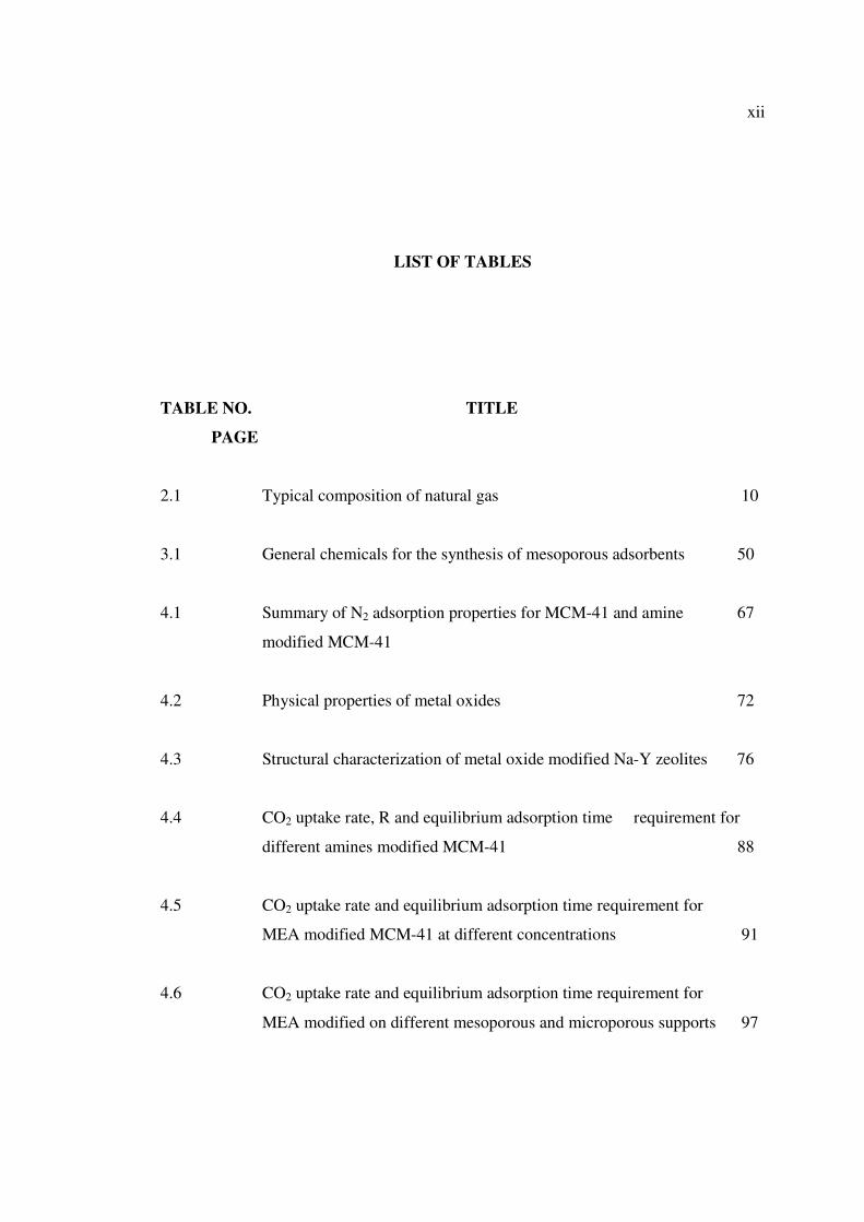
LIST OF TABLES
TABLE NO. TITLE
PAGE
2.1 Typical composition of natural gas 10
3.1 General chemicals for the synthesis of mesoporous adsorbents 50
4.1 Summary of N2 adsorption properties for MCM-41 and amine 67
modified MCM-41
4.2 Physical properties of metal oxides 72
4.3 Structural characterization of metal oxide modified Na-Y zeolites 76
4.4 CO2 uptake rate, R and equilibrium adsorption time requirement for
different amines modified MCM-41 88
4.5 CO2 uptake rate and equilibrium adsorption time requirement for
MEA modified MCM-41 at different concentrations 91
4.6 CO2 uptake rate and equilibrium adsorption time requirement for
MEA modified on different mesoporous and microporous supports 97

xiii
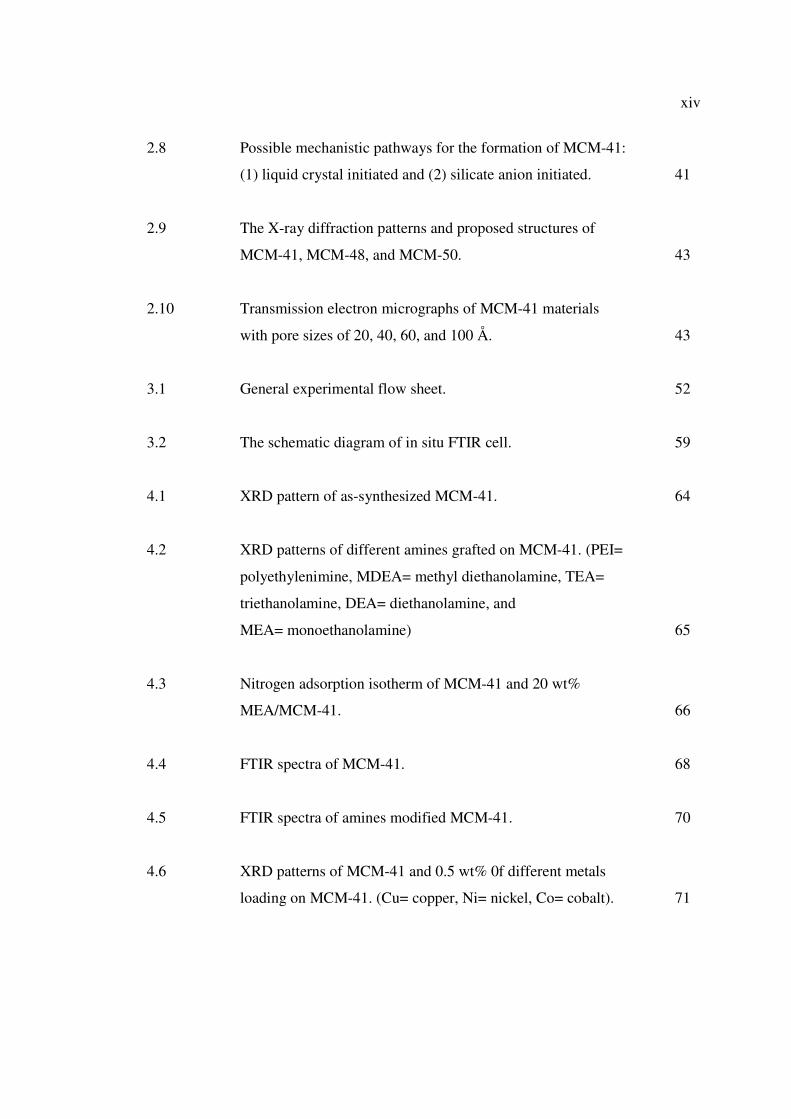
LIST OF FIGURES
FIGURE NO. TITLE
PAGE
2.1 Total sources of energy consumed in U.S. for 2000 12
2.2 Natural gas use by sector 13
2.3 Schematic view of cryogenic heat exchanger showing the
manifolds (6) and nozzles (7) 15
2.4 IUPAC classification of adsorption isotherms. 25
2.5 A 5-1 secondary building unit and the MFI structure. 35
2.6 Structures of four selected zeolites (from top to bottom: faujasite
or zeolites X, Y; zeolite ZSM-12; zeolite ZSM-5 or silicalite-1;
zeolite Theta-1 or ZSM-22) and their micropore systems and
dimensions. 37
2.7 The formation of microporous molecular sieves using individual
small alkyl chain length quaternary directing agents (top) and the
formation of mesoporous molecular sieves using long alkyl chain
length quaternary directing agents (bottom). 39
xiv
2.8 Possible mechanistic pathways for the formation of MCM-41:
(1) liquid crystal initiated and (2) silicate anion initiated. 41
2.9 The X-ray diffraction patterns and proposed structures of
MCM-41, MCM-48, and MCM-50. 43
2.10 Transmission electron micrographs of MCM-41 materials
with pore sizes of 20, 40, 60, and 100 Å. 43
3.1 General experimental flow sheet. 52
3.2 The schematic diagram of in situ FTIR cell. 59
4.1 XRD pattern of as-synthesized MCM-41. 64
4.2 XRD patterns of different amines grafted on MCM-41. (PEI=
polyethylenimine, MDEA= methyl diethanolamine, TEA=
triethanolamine, DEA= diethanolamine, and
MEA= monoethanolamine) 65
4.3 Nitrogen adsorption isotherm of MCM-41 and 20 wt%
MEA/MCM-41. 66
4.4 FTIR spectra of MCM-41. 68
4.5 FTIR spectra of amines modified MCM-41. 70
4.6 XRD patterns of MCM-41 and 0.5 wt% 0f different metals
loading on MCM-41. (Cu= copper, Ni= nickel, Co= cobalt). 71
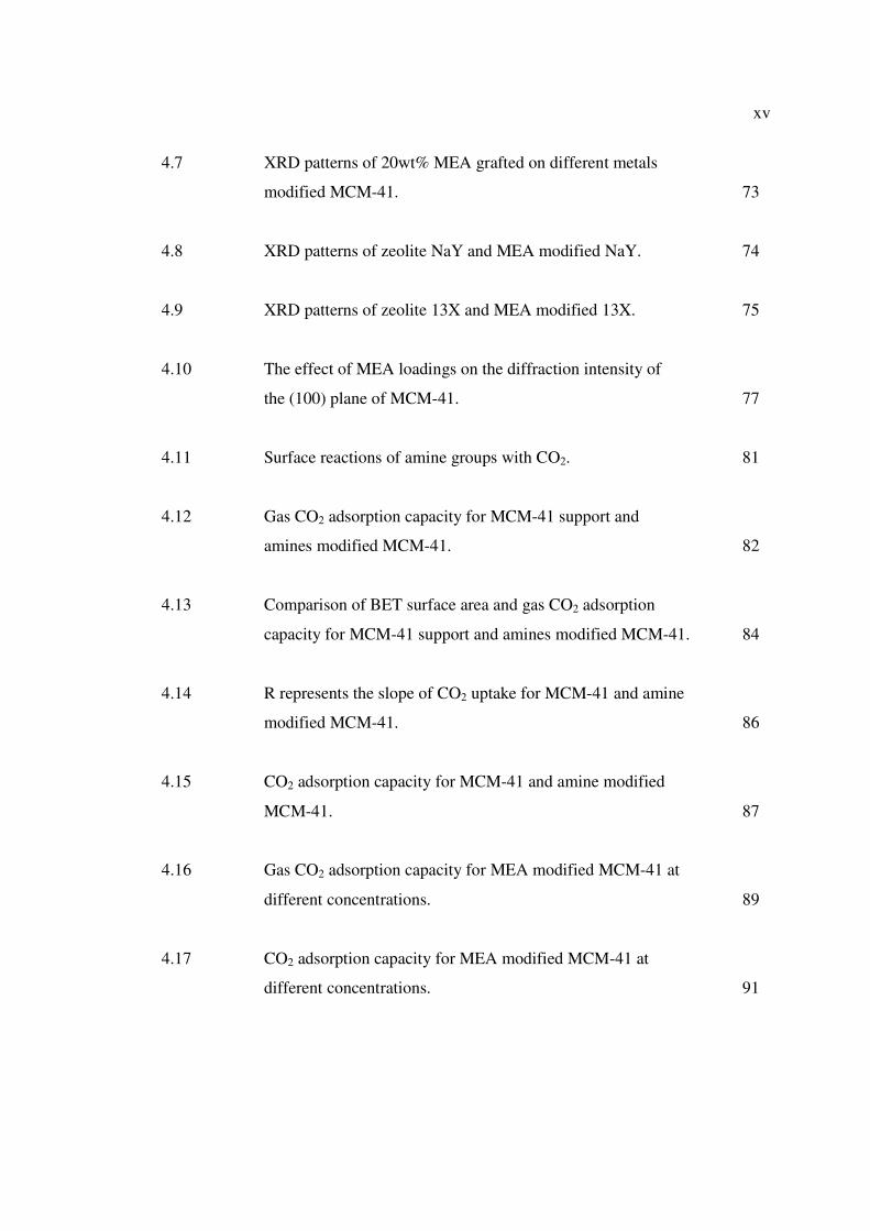
xv
4.7 XRD patterns of 20wt% MEA grafted on different metals
modified MCM-41. 73
4.8 XRD patterns of zeolite NaY and MEA modified NaY. 74
4.9 XRD patterns of zeolite 13X and MEA modified 13X. 75
4.10 The effect of MEA loadings on the diffraction intensity of
the (100) plane of MCM-41. 77
4.11 Surface reactions of amine groups with CO2. 81
4.12 Gas CO2 adsorption capacity for MCM-41 support and
amines modified MCM-41. 82
4.13 Comparison of BET surface area and gas CO2 adsorption
capacity for MCM-41 support and amines modified MCM-41. 84
4.14 R represents the slope of CO2 uptake for MCM-41 and amine
modified MCM-41. 86
4.15 CO2 adsorption capacity for MCM-41 and amine modified
MCM-41. 87
4.16 Gas CO2 adsorption capacity for MEA modified MCM-41 at
different concentrations. 89
4.17 CO2 adsorption capacity for MEA modified MCM-41 at
different concentrations. 91

xvi
4.18 Gas CO2 adsorption capacity for various mesoporous and
microporous supports and MEA modified supports. 94
4.19 TGA curves of CO2 adsorption capacity for MEA modified
mesoporous and microporous supports. 96
4.20 Gas CO2 adsorption capacity for 20 wt% MEA modified
MCM-41 at different adsorption temperatures. 99
4.21 Slope, R represent rate of CO2 uptake for 20 wt% MEA
modified MCM-41 at different adsorption temperatures. 100
4.22 Gas CO2 adsorption capacity for 20 wt% MEA modified
MCM-41 at different heating temperatures. 102
4.23 Slope, R represent rate of CO2 uptake for 20 wt% MEA
modified MCM-41 at different heating temperatures. 103
4.24 FTIR spectra of CO2 adsorbed on: (a) MCM-41; (b) 20 wt%
MEA/MCM-41; (c) 20 wt% DEA/MCM-41; (d) 20 wt%
TEA/MCM-41; (e) 20 wt% MDEA/MCM-41; and (f) 20 wt%
PEI/MCM-41 at equilibrium pressures of 138 kPa and 25˚C. 105
4.25 The corresponding areas of the FTIR spectrum peak at
(1520 – 1420 cm-1 region) versus the amount of CO2 adsorbed
on amine modified MCM-41. 107
4.26 Schematic diagram of CO2 adsorption on amine modified
mesoporous silica. 108
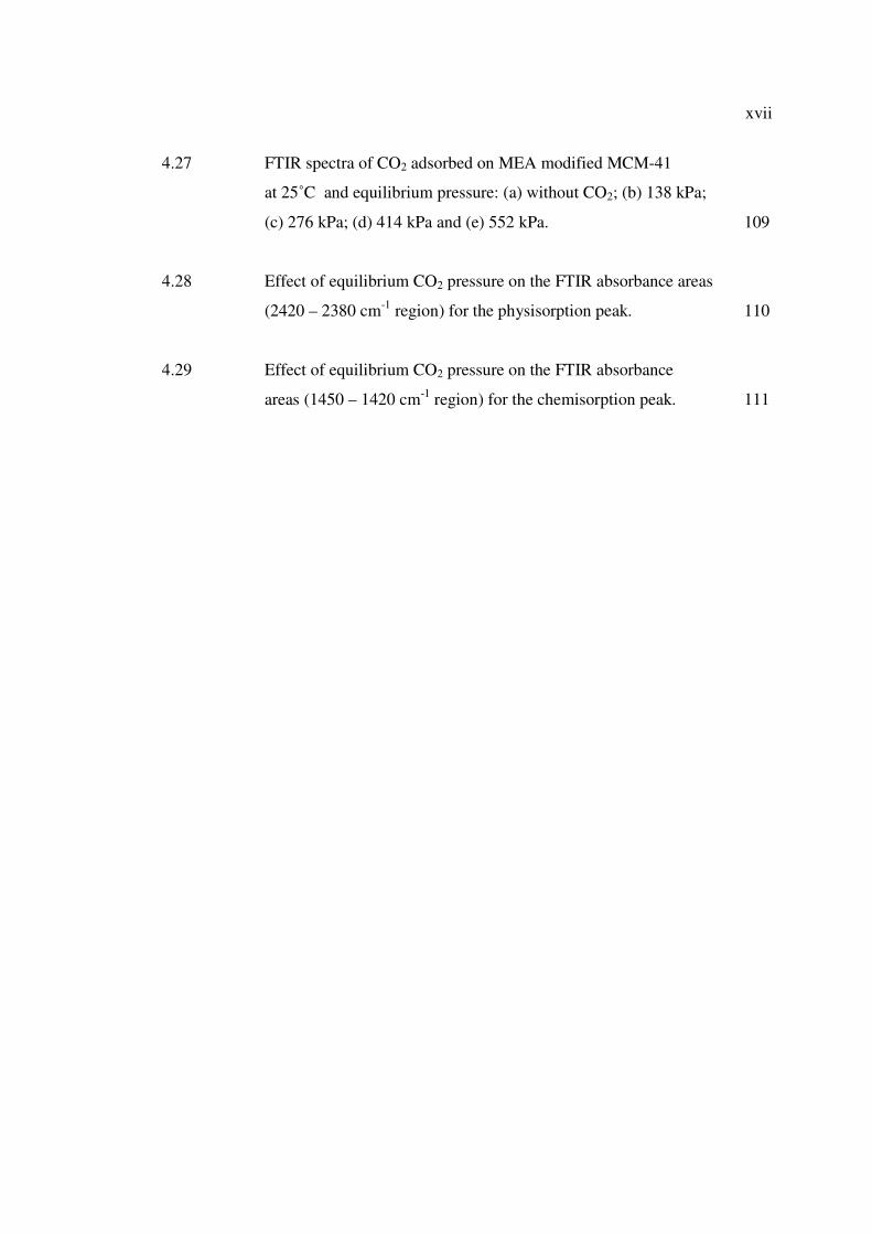
xvii
4.27 FTIR spectra of CO2 adsorbed on MEA modified MCM-41
at 25˚C and equilibrium pressure: (a) without CO2; (b) 138 kPa;
(c) 276 kPa; (d) 414 kPa and (e) 552 kPa. 109
4.28 Effect of equilibrium CO2 pressure on the FTIR absorbance areas
(2420 – 2380 cm-1 region) for the physisorption peak. 110
4.29 Effect of equilibrium CO2 pressure on the FTIR absorbance
areas (1450 – 1420 cm-1 region) for the chemisorption peak. 111
xviii
LIST OF SYMBOLS
0 C - Degree Celsius
T - Temperature (K)
d - Spacing of indices planes
h - Miller indices planes
k - Miller indices planes
l - Miller indices planes
% - Percentage
θ - Angle
λ - Wavelength
Irel - Relative Intensity
wt. - Weight
Å - Angstrom (1Å = 10-10 m)
A - Absorbance
a.u. - Arbitrary unit
xix
LIST OF ABBREVIATIONS
FTIR - Fourier Transform Infrared Spectroscopy
US - United State
BET - Brunauer, Emmett, Teller
XRD - X-Ray Diffraction
SEM - Scanning Electron Microscope
TEM - Transmission Electron Microscope
TGA - Thermogravimetric Analyzer
MEA - Monoethanolamine
DEA - Diethanolamine
TEA - Triethanolamine
MDEA - Methyl diethanolamine
PEI - Polyethylenimine
xx
LIST OF APPENDICES
APPENDIX TITLE PAGE
A Calculation of amines 130
B Carbon dioxide capture capacity measurement 132
1
CHAPTER 1
INTRODUCTION
1.1 Introduction to CO2 Adsorption
Malaysia has a vast reserve of natural gas, which places the country as the 13th
largest gas reserves in the world in year 2001 (Anon,2005). As at 31 December 2003,
Malaysia‟s gas reserves stood at 89.02 trillion standard cubic feet. At the current
production rate, the gas reserve is estimated to last another 50 years (Anon, 2005).
Recently, Malaysia is increasingly turning to natural gas from oil, not only as a source
of energy, but also as a raw material in the manufacture of various petrochemical
products. Natural Gas for Vehicle (NGV) program has diversified the use of natural gas
into a new era.
However, before natural gas reaches the market place, numerous separation
processes must be performed because the naturally occurring natural gas is a complex
mixture containing many diverse components such as hydrocarbons (light, heavy,
aromatic), water, sulfur components, carbon dioxide, nitrogen, mercury and other
impurities. Therefore, there is a need to exploit cost-effective separation processes to

2
produce good quality gas (Daiminger, 2004). Carbon dioxide removal from natural gas
attracts more attention than other impurities due to its corrosiveness and inert property.
Up to date, the capture and separation of CO2 can be achieved by different approaches,
namely chemical and physical absorption using solvents, solid physical adsorption,
cryogenic techniques and membrane separation (Gray et al., 2004; Meisen and Shuai,
1997). Among the approaches used, amine based chemical absorption have been used
commercially for CO2 capturing plant. However, the liquid amine based processes pose
operating difficulties due to the challenge of keeping the solvent clean and operating
within the process constraints of the system (Daiminger, 2004). Besides, this process
also suffers from high regeneration energy, large equipment size, solvent leakage from
piping system and also equipment corrosion problem (Xu et al., 2005). Therefore, many
researchers have switched the work to another promising method, which is adsorption
process due to its low energy requirement, cost advantage and ease of applicability over
a relatively wide range of temperatures and pressures (Xu et al., 2003; Xu et al., 2005).
Developing an adsorbent with high CO2 adsorption capacity and high selectivity has
now become the major challenge in the research of adsorption separation.
The discovery of zeolites by the Swedish scientist Cronstedt in 1756 until the
introduction of synthetic zeolites in 1954 by Union Carbide as a new class of industrial
adsorbents has proved the versatility of zeolites as good molecular sieve (Ghobarkar et
al., 1999). Besides, zeolites also possess large internal pore volumes, molecular-size
pores, regularity of crystal structures and diverse framework chemical composition,
which enable them to be tailor-made into different structure and properties. Therefore,
zeolites have been widely investigated as adsorbents for carbon dioxide separation
(Sherman, 1999; Weitkamp, 2000; Ghobarkar et al., 1999).
In addition, the continuous research on the literature of design, synthesis,
characterization and property evaluation of zeolites and molecular sieves for catalysis,
adsorption and separation has driven the discovery of the M41S family of ordered

3
mesoporous adsorbents by scientists at Mobil Oil (Zhao et al., 1996; Kumar et al., 2001;
Kresge et al., 1992). Among the M41S family, the two most investigated materials are
the MCM-41 with a 2-D hexagonal structure and the MCM-48 with a 3-D cubic
structure (Kumar et al., 2001). These highly ordered pore systems with tunable pore
sizes, large specific surface areas and pore volumes, and high density of surface silanols
provide excellent opportunities in inclusion chemistry. A large number of
functionalizing entities including both organic and inorganic ligands have been
introduced in the channels to generate catalysts, adsorbents, and to improve the
hydrothermal and mechanical stabilities (Zhao et al., 1996; Zhao et al., 2000).
Discovery of the M41S family of molecular sieves has led to significant progress
in the synthesis and characterization of ordered mesoporous materials. Large pore-size
molecular sieves are much in demand for reactions or separations and the development
of mesoporous structure has resulted in the preparation of well-ordered hexagonal
mesoporous silica structures (SBA-15) with uniform pore sized up to approximately 300
angstroms (Stucky et al., 1998). SBA-15 which is a polymer-templated silica with
hexagonally ordered mesopores has larger pore size, thicker pore walls and higher
hydrothermal stability in comparison to MCM-41, which is surfactant-templated ordered
mesoporous material.
The polymer employ to obtain SBA-15, poly(ethylene oxide)-poly(propylene
oxide)-poly(ethylene oxide) (PEO-PPO-PEO), is biodegradable and cheaper than the
surfactant used in the synthesis of MCM-41 (Fulvio et al., 2005). Another feature of
SBA-15 is the existence of micropores interconnecting hexagonally ordered mesopores,
which make it more suitable for catalysis because these interconnections facilitate
diffusion inside the entire porous structure (Tatiana Klimova et al., 2006; Fulvio et al.,
2005). These ordered structure with various pore sizes characteristic are suitable for
either microporous or mesoporous materials to be use as support materials in
modification of adsorbents.
4
Physical sorbents such as zeolites and carbon molecular sieves can reversibly
adsorb a large quantity of CO2 at room temperature. However, their capacity diminishes
quickly at elevated temperature and the selectivity over water is poor. Amine functional
groups are useful for CO2 removal because of their ability to form ammonium
carbamates and carbonates reversibly at moderate temperature (Gray et al., 2005). The
incorporation of organic amines into a porous support is a promising approach for CO2
sorbents combining good capacity and selectivity at moderate temperature (Zheng et al.,
2005; Xu et al., 2002; Xu et al., 2003; Khatri et al., 2005).
Recently, the latest development of zeolites has been proposed with their new
concept of CO2 “molecular basket” for developing high-capacity, highly-selective CO2
adsorbents, which can be operated at elevated temperature (Xu et al., 2003). This novel
CO2 “molecular basket” adsorbents are developed based on polyethyleimine (PEI)-
modified mesoporous molecular sieve of MCM-41 type and shows high CO2 adsorption
capacity, which is 30 times higher than MCM-41 and more than twice of the pure PEI
(Xu et al., 2003). Therefore, the proposed research will use the above mentioned
concept to develop new amine modified porous materials as CO2 adsorbents. Different
alkanolamines including primary, secondary and tertiary amines will be used as the
amine source and incorporated onto different type of support materials.
1.2 Research Background
Current technologies deploy at commercial scale for CO2 removal use processes
based on chemical absorption with alkanoamine such as monoethanolamine (MEA)
solvent. However, the liquid amine-based processes suffer from high regeneration

5
energy, large equipment size, solvent degradation and equipment corrosion (Xu et al.,
2005).
To overcome these disadvantages, several other separation technologies, such as
adsorption, membrane and cryogenic separation have been studied. Over all the
technologies, adsorption separation attracts more interest because of the low energy
requirement, cost advantage, and ease of applicability over a relatively wide range of
temperature and pressure. Therefore, regenerable solid sorbents will be a promising
alternative that can potentially offer several advantages over liquid amine systems such
as ease in handling of solids, reduced toxicity and corrosiveness (Rajesh et al., 2005).
Besides that, regenerable solid CO2 sorbents are also favorable for applications in
enclosed environments, such as submarines and spacecraft.
Various porous supports impregnated with liquid amines have been reported and
such hybrid sorbents have been used successfully onboard space vehicles for crew air
scrubbing (Zheng et al., 2005). However, loss of amine components due to evaporation
is a problem at moderate temperature. By grafting of amine functional groups directly to
the surface of a physical sorbent, the evaporation problem can be eliminated and the
overall thermal stability can be improved (Khatri et al., 2005; Xu et al., 2002). The key
issue for adsorption separation is to develop an adsorbent with high CO2 adsorption
capacity and high CO2 selectivity which will be the main objectives of this study.

6
1.3 Objectives and Scopes of Study
Several objectives have been specified in this research including synthesis of
amine-modified adsorbents for carbon dioxide adsorption, the characterization of the
physical and chemical properties of the synthesized adsorbents and the study of the
carbon dioxide adsorption and desorption capacity. To be specific, two main objectives
of this research are to study the effects of different type of amines on the adsorbents and
the effects of different supporting materials, mesoporous materials and microporous
materials by using one specific amine as standard (which is monoethanolamine, MEA)
on the performance of carbon dioxide adsorption.
The main scopes in this research work is to achieve the specified objectives
comprises of research activities such as preparation and modification of the adsorbents,
the characterization of the adsorbents and the adsorption capacity study specifically for
carbon dioxide separation. Two types of mesoporous adsorbents will be synthesis in this
study as the supporting materials are MCM-41 and SBA-15. Meanwhile, other support
materials such as zeolite NaY and 13X are obtained commercially.
After preparation of the support materials, the modification step is implemented
by loading different types of amine groups into the adsorbents using freeze drying
method. The characterization of chemical and physical properties of modified
adsorbents such as the structure properties, the pore diameter distribution, the pore
volume as well as the surface area are determined by X-ray diffraction (XRD) and N2
adsorption/ desorption method using Quantachrome equipment. Meanwhile, thermal
gravimetric analyzer (TGA) is used to study the performance of carbon dioxide
adsorption for the modified adsorbents.
7
Other than adsorption capacity study, the modified adsorbents that have a good
physical and chemical properties as well as adsorption properties such as good structure
and high adsorption capacity is used as the standard adsorbent for the study of other
parameters by varying amine concentration, adsorption temperatures, heating
temperatures and carbon dioxide gas pressure for in situ adsorption study.
1.4 Report Outline
This thesis consists of five chapters which describes the research in a sequential
order. Chapter 1 introduces the research background on amine modified adsorbents,
problems encountered by the industry, and underlined objectives to solve the problems.
Chapter 2 provides the literature review of the general aspects related to the field of
research study. This includes natural gas processing, adsorption isotherms and
mechanism, fundamental of microporous and mesoporous materials, modification of
adsorbents and gas adsorption characteristics. Chapter 3 describes the materials and
methods applied in the experimental study and adsorbents characterization in detail
while the results and discussion of the findings are included in Chapter 4. Lastly,
Chapter 5 summarized the results as well as the findings of the study and some
recommendations for future work.

8
1.5 Summary
Ordered mesoporous and microporous materials on its own may have high
performance as catalysts or as highly selective adsorbents. The modification of these
adsorbents using different type of amines will create a combination of various
physicochemical properties to produces more advance materials in many fields with
additional functionality. Through this study, carbon dioxide adsorptive characteristics of
amine modified adsorbents are well study and explain thoroughly for clear
understanding. The fundamental results and findings obtained will enable researchers to
carry on the work to design new gas adsorbents with higher adsorption capacity,
selectivity and reversibility.
CHAPTER 2
LITERATURE REVIEW
2.1 Introduction to Natural Gas
Natural gas is nothing new. In fact, most of the natural gas that is brought out
from under the ground is millions and millions of years old. However, it was not until
recently that methods for obtaining this gas, bringing it to the surface, and putting it to
use were developed.
Natural gas is a colorless, shapeless, and odorless gas in its pure form. Natural
gas is combustible, and when burned it gives off a great deal of energy. Unlike other
fossil fuels, however, natural gas is clean burning and emits lower levels of potentially
harmful byproducts into the air. Energies are required constantly in various fields, for
transportations, cooking, generate electricity and many more. It is this need for energy
that has elevated natural gas to such a level of importance in our society and in our lives
(Anon, 2005).

10
2.1.1 Fundamental of Natural Gas
Natural gas is a combustible mixture of hydrocarbon gases. While natural gas is
formed primarily of methane, it can also include ethane, propane, butane and pentane.
The composition of natural gas can vary widely, below is a chart outlining the typical
makeup of natural gas before it is refined. From Table 2.1, it is clearly shows that
carbon dioxide is the highest impurities (up to 8%) compare to others. Since the
presence of carbon dioxide tend to cause corrosive and inert property problem, therefore
it is necessary to remove this unwanted gas.
Table 2.1: Typical composition of natural gas (Anon, 2005).
Composition Molecule Formula Percentage
Methane CH4 70 – 90%
Ethane C2H6
0 – 20% Propane C3H8
Butane C4H10
Carbon Dioxide CO2 0 – 8%
Oxygen O2 0 – 0.2%
Nitrogen N2 0 – 5%
Hydrogen Sulphide H2S 0 – 5%
Rare Gases A, He, Ne, Xe trace
In its purest form, such as the natural gas used in Natural Gas Vehicles (NGV), it
is almost pure methane. Methane is a molecule made up of one carbon atom and four
hydrogen atoms, and is referred to as CH4. Ethane, propane, and the other hydrocarbons
commonly associated with natural gas have different chemical formulas.
11
Natural gas is considered 'dry' when it is almost pure methane, having had most of the
other commonly associated hydrocarbons removed. When other hydrocarbons are
present, the natural gas is considered 'wet' gas.
Natural gas has many uses, residentially, commercially, and industrially. Natural
gas can be found in reservoirs underneath the earth and is commonly associated with oil
deposits. Production companies search for evidence of these reservoirs by using
sophisticated technology that helps to find the location of the natural gas, and drill wells
in the earth where it is likely to be found. Once brought from underground, the natural
gas is refined to remove impurities like water, other gases, sand, and other compounds.
Some hydrocarbons are removed and sold separately, including propane and butane.
Other impurities are also removed, like hydrogen sulfide (the refining of which can
produce sulfur, which is then also sold separately). After refining, the clean natural gas
is transmitted through a network of pipelines. From these pipelines, natural gas is
delivered to its point of use.
2.1.2 Uses of Natural Gases
For hundreds of years, natural gas has been known as a very useful substance.
The Chinese discovered a very long time ago that the energy in natural gas could be
harnessed, and used to heat water. In the early days of the natural gas industry, the gas
was mainly used to light streetlamps, and the occasional house. However, with much
improved distribution channels and technological advancements, natural gas is being
used in ways never thought possible.
12
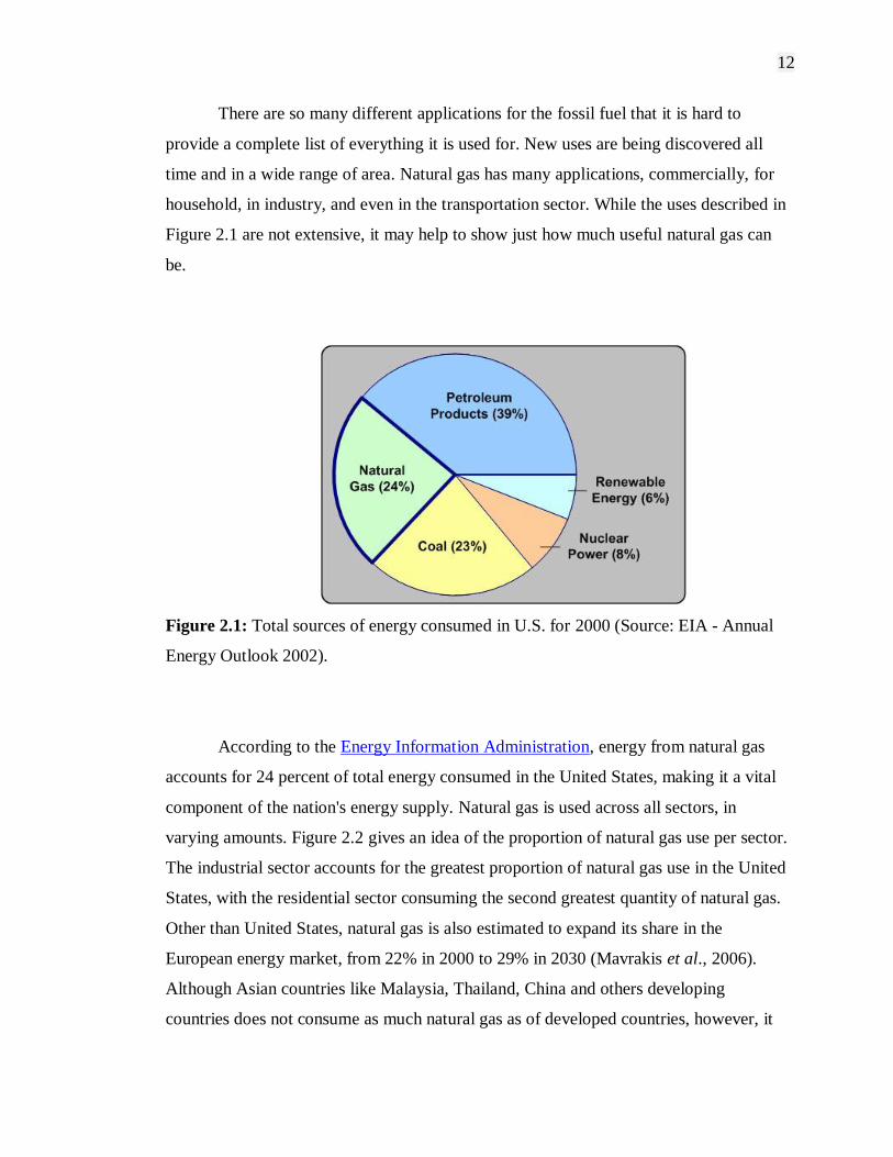
There are so many different applications for the fossil fuel that it is hard to
provide a complete list of everything it is used for. New uses are being discovered all
time and in a wide range of area. Natural gas has many applications, commercially, for
household, in industry, and even in the transportation sector. While the uses described in
Figure 2.1 are not extensive, it may help to show just how much useful natural gas can
be.
Figure 2.1: Total sources of energy consumed in U.S. for 2000 (Source: EIA - Annual
Energy Outlook 2002).
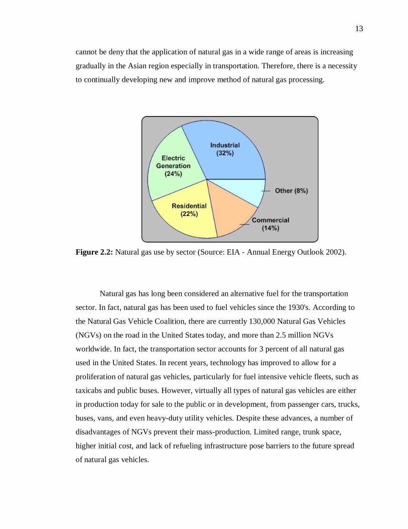
According to the Energy Information Administration, energy from natural gas
accounts for 24 percent of total energy consumed in the United States, making it a vital
component of the nation's energy supply. Natural gas is used across all sectors, in
varying amounts. Figure 2.2 gives an idea of the proportion of natural gas use per sector.
The industrial sector accounts for the greatest proportion of natural gas use in the United
States, with the residential sector consuming the second greatest quantity of natural gas.
Other than United States, natural gas is also estimated to expand its share in the
European energy market, from 22% in 2000 to 29% in 2030 (Mavrakis et al., 2006).
Although Asian countries like Malaysia, Thailand, China and others developing
countries does not consume as much natural gas as of developed countries, however, it
13
cannot be deny that the application of natural gas in a wide range of areas is increasing
gradually in the Asian region especially in transportation. Therefore, there is a necessity
to continually developing new and improve method of natural gas processing.
Figure 2.2: Natural gas use by sector (Source: EIA - Annual Energy Outlook 2002).
Natural gas has long been considered an alternative fuel for the transportation
sector. In fact, natural gas has been used to fuel vehicles since the 1930's. According to
the Natural Gas Vehicle Coalition, there are currently 130,000 Natural Gas Vehicles
(NGVs) on the road in the United States today, and more than 2.5 million NGVs
worldwide. In fact, the transportation sector accounts for 3 percent of all natural gas
used in the United States. In recent years, technology has improved to allow for a
proliferation of natural gas vehicles, particularly for fuel intensive vehicle fleets, such as
taxicabs and public buses. However, virtually all types of natural gas vehicles are either
in production today for sale to the public or in development, from passenger cars, trucks,
buses, vans, and even heavy-duty utility vehicles. Despite these advances, a number of
disadvantages of NGVs prevent their mass-production. Limited range, trunk space,
higher initial cost, and lack of refueling infrastructure pose barriers to the future spread
of natural gas vehicles.
14
Most natural gas vehicles operate using compressed natural gas (CNG). This
compressed gas is stored in similar fashion to a car's gasoline tank, attached to the rear,
top, or undercarriage of the vehicle in a tube shaped storage tank. A CNG tank can be
filled in a similar manner, and in a similar amount of time, to a gasoline tank. This
natural gas fuels a combustion engine similar to engines fueled by other sources.
However, in a NGV, several components require modification to allow the engine to run
efficiently on natural gas. In addition to using CNG, some natural gas vehicles are
fueled by Liquefied Natural Gas (LNG). Some natural gas vehicles that exist today are
bi-fuel vehicles, meaning they can use gasoline or natural gas, allowing for more
flexibility in fuel choice.
2.1.3 Natural Gas Processing
The natural gas purchased by consumers consists almost entirely of methane, the
simplest hydrocarbon. In gas reservoirs, however, methane is typically found with
heavier hydrocarbons such as ethane, propane, butane and pentane. The raw gas also
contains water vapor, hydrogen sulphide, carbon dioxide, nitrogen and other gases that
are removed from the gas stream at processing plants.
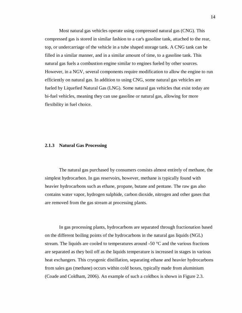
In gas processing plants, hydrocarbons are separated through fractionation based
on the different boiling points of the hydrocarbons in the natural gas liquids (NGL)
stream. The liquids are cooled to temperatures around -50 °C and the various fractions
are separated as they boil off as the liquids temperature is increased in stages in various
heat exchangers. This cryogenic distillation, separating ethane and heavier hydrocarbons
from sales gas (methane) occurs within cold boxes, typically made from aluminium
(Coade and Coldham, 2006). An example of such a coldbox is shown in Figure 2.3.

15
Figure 2.3: Schematic view of cryogenic heat exchanger showing the manifolds (6) and
nozzles (7) (Coade and Coldham, 2006).
2.1.4 Carbon Dioxide Removal from Natural Gas
Fossil fuels will likely remain the mainstay of energy supply well into the 21st
century. Availability of these fuels to provide clean, affordable energy is essential for
the prosperity and the security of the world. However, increased CO2 concentration in
the atmosphere due to emissions of CO2 from fossil fuel combustion has caused
concerns about global warming. Improving the efficiency of energy utilization and
increasing the use of low-carbon energy sources are considered to be potential ways to
reduce CO2 emissions. Recently, CO2 capture and sequestration are receiving significant
attention and being recognized as a third option for reduction in the global CO2 emission
(Khatri et al., 2005; Kaggerud et al., 2006). Furthermore, enriched CO2 streams can be
an important starting material for synthetic clean fuels and chemicals. For carbon
16
sequestration, the cost for CO2 capture is expected to comprise about 75% of the total
costs for geological or oceanic sequestration, with the other 25% costs attribute to
transportation and injection. Therefore, the development of techniques for the cost-
effective separation and capture of CO2 is considered to be one of the highest priorities
in the field of carbon sequestration (Xu et al., 2002; Xu et al., 2005).
2.1.4.1 Adsorption as a Method for CO2 Removal
Adsorption is one of the promising methods that could be applicable for
separating CO2 from gas mixtures, and numerous studies have been conducted on
separation of CO2 by adsorption in the last two decades. Various adsorbents, such as
activated carbons, pillared clays, metal oxides, and zeolites have been investigated.
At lower temperatures (room temperature), the zeolite-based adsorbents have generally
been found to show higher adsorption capacity. CO2 adsorption capacity of zeolite 13X,
zeolite 4A, and activated carbon was about 160, 135, and 110 mg/g-adsorbent,
respectively, at 25 °C and 1 atm CO2 partial pressure. However, their adsorption
capacities rapidly decline with increasing temperature (Zheng et al., 2005). Moreover,
since all the gases are physically adsorbed into/onto these adsorbents, the separation
factors (such as CO2/N2 ratio) are low. To operate at relatively high temperature and
reach a high separation factor, chemical adsorption was adopted. Investigation of the
adsorption performance of hydrotalcite showed a CO2 adsorption capacity of 22 mg/ g-
adsorbent at 400 °C and 0.2 atm CO2 partial pressure. Meanwhile, MgO showed an
adsorption capacity of 8.8 mg/g-adsorbent at 400 °C. Both types of adsorbents need high
temperature operation and have a low adsorption capacity, thus they are not suitable for
practical use for CO2 separation (Desideri and Paolucci, 1999; Xu et al., 2002; Xu et al.,
2005).

17
For practical applications, selective adsorbents with high capacity are desired.
Many of the separations should preferably be operated at relatively higher temperature,
for example, higher than room temperature and up to ~150 °C which is a typical value
of power plant stack temperature (Pedersen et al., 1995; Kaggerud et al., 2006).
Developing an adsorbent with high CO2 selectivity and high CO2 adsorption capacity,
which can also be operated at relatively high temperature, is desired for more efficient
CO2 separation by an adsorption method.
2.1.4.2 Adsorbent for CO2 Removal
A new concept called “molecular basket” is being discovered to develop a high
capacity, highly selective CO2 adsorbent (Xu et al., 2002). A novel type of solid
adsorbent has been discovered, which can serve as a “molecular basket” for “packing”
CO2 in condensed form in the nanoporous channels. To capture a large amount of CO2
gas, the adsorbent needs to have large pore channels filled with a CO2 capturing
substance as the “basket”. To cause the “basket” to be a CO2 “molecular basket”, a
substance with numerous CO2 affinity sites should be loaded into the pores of the
support to increase the affinity between the adsorbent and CO2 and as a result, the CO2
adsorption selectivity and CO2 adsorption capacity can be increased. In addition, the
adsorption affinity to CO2 by the CO2 –philic substance increased in the confined
mesoporous environment and therefore the mesoporous molecular sieve can have a
synergetic effect on the adsorption of CO2 by CO2 –philic substance (Xu et al., 2003; Xu
et al., 2005).

18
2.1.4.3 Amine Solutions as Carbon Dioxide Removal System
Several techniques to remove CO2 from gas mixtures have been studied since
1970, but most of them were applied to produce technical CO2 as process gas, mainly for
the food and chemical industry. In the following decade, some of the CO2 capture
systems were considered for application in power plants and separation of natural gas.
With the discovery of increased number of natural gas fields, more power plants are
converting to the use of natural gas.
Among the alternative for CO2 capture, chemical absorption with amine aqueous
solutions was demonstrated as one of the most mature and less expensive technologies
to be applied to power plants. The absorption stripping system is particularly interesting
because of its possibility to regenerate the solution continuously, thereby in an almost
closed cycle (Desideri and Paolucci, 1999; Xu et al., 2005). The plant for removing CO2
from flue gases has two main elements, which are the absorption and stripping packed
columns. This will allows a continuous regeneration of the amine solution, which saves
considerable amounts of solvent. Amines in the water solution react with CO2 in the
absorption column, forming chemical compounds that separate CO2 from the gas
mixtures at a higher rate than the natural CO2 absorption in pure water (Desideri and
Paolucci, 1999).
To date, all commercial CO2 capture plants use processes based on chemical
absorption with alkanolamine such as monoethanolamine (MEA) solvent. An example is
the Fluor Econamine process. However, the liquid amine-based processes suffer from
high regeneration energy, large equipment size, solvent degradation and equipment
corrosion. To overcome these disadvantages, several other separation technologies, such
as, adsorption, membrane and cryogenic separation have been studied. Because of the
low energy requirement, cost advantage, and ease of applicability over a relatively wide
19
range of temperatures and pressures, adsorption separation attracts much interest. The
main target for adsorption separation is to develop an adsorbent with high CO2
adsorption capacity and high CO2 selectivity (Desideri and Paolucci, 1999; Xu et al.,
2003; Xu et al., 2005).
2.2 Adsorption Process
Most of the physical, chemical and biological processes take place at the
boundary between two phases, while others are initiated at that interface. The change in
concentration of a given substance at the interface as compared with the neighboring
phases is referred to as adsorption (Sing, 1998; Dabrowski, 2001). Depending on the
type of phases in contact, adsorption process can be divided into following systems:
Liquid-gas
Liquid-liquid
Solid-liquid
Solid-gas
The major development of adsorption processes on a large, industrial scale deals
mainly with the solid-gas and solid-liquid interfaces, but in various laboratory separation
techniques all types of interfaces are applied. The term „fluid‟ is commonly used to
denote gas or liquid in contact with the boundary surface of solids.
20
2.2.1 Adsorption Concept
A basic concept in adsorption occurring at every interface is the real adsorption
system. By considering this concept in terms of solid-gas interface, the real adsorption
system can be defined as an equilibrium including the adsorbent being in contact with
the bulk phase and the interfacial layer. This layer consists of two regions which are the
part of gas residing in the force field of the solid surface and the surface layer of the
solid. The term „adsorption‟ deals with the process in which molecules accumulate in
the interfacial layer, but desorption denotes the converse process.
Adsorption hysteresis is said to occur when the adsorption and desorption curves
deviate from one another. In such a case the isotherm possesses a hysteresis loop, the
shape of which varies from one adsorption system to another. Hysteresis loops are
mostly with mesoporous solids, where the so-called capillary condensation occurs. The
material in the adsorbed state is defined as the „adsorbate‟, but that in the bulk gas or
vapor phase prior to being adsorbed is called the „adsorptive‟. The penetration by the
adsorbate molecules into the bulk solid phase is determined as „absorption‟. The term
„sorption‟ together with the terms „sorbent‟, „sorbate‟ and „sorptive‟ is also used to
denote both adsorption and absorption, when both occur simultaneously or cannot be
distinguished (Sing, 2004; Sing, 1998; Dabrowski, 2001).
The fundamental concept in adsorption science is that named as the adsorption
isotherm. It is the equilibrium relation between the quantity of the adsorbed material and
the pressure or concentration in the bulk fluid phase at constant temperature. Apart from
the results of the calorimetric measurements, the adsorption isotherm is the primary
source of information on the adsorption process.
21
A complete statistical description is especially complicated by the heterogeneity
of the solid materials which include porous adsorbents, as for the majority of industrial
adsorbents. Assuming thermodynamic equilibrium between the surface and bulk phases,
various adsorption isotherms can be derived by utilizing the equality of the chemical
potentials of a given component in coexisting phases. The analytical forms of these
equations depend on the assumed models for the surface and bulk phases. The surface
phase may be considered as a monolayer or multilayer, and as localized, mobile or
partially mobile. The analytical forms of adsorption isotherms are complex due to
structural and energetic heterogeneity of the solid surfaces, which is characteristic of a
great number of adsorbents used in practice (Sing, 1998; Choma et al., 2003;
Dabrowski, 2001)..
2.2.2 Types of Adsorption
2.2.2.1 Ion Exchange
The equilibrium between a bulk phase and the surface layer may be established
with regard to neutral or ionic particles. If the adsorption process of one or several ionic
species is accompanied by the simultaneous desorption of an equivalent amount of ionic
species, this process is considered as an ion exchange.

22
2.2.2.2 Physisorption
Adsorption can result either from the universal van der Waals interactions
(physical adsorption, physisorption) or it can have the character of a chemical process
(chemical adsorption or chemisorption). Physical adsorption can be compared to the
condensation process of the adsorptive. As a rule, it is a reversible process that occurs at
a temperature lower or close to the critical temperature of an adsorbed substance.
Therefore, physical adsorption is very effective particularly at a temperature close to the
critical temperature of a given gas.
2.2.2.3 Chemisorption
Contrary to physisorption, chemisorption occurs only as a monolayer (Adamson,
1996). Chemisorption occurs usually at temperatures much higher than the critical
temperature and by contrast to physisorption is a specific process which can only take
place on some solid surfaces for a given gas. Under favourable conditions, both
processes can occur simultaneously or alternately. Physical adsorption is accompanied
by a decrease in free energy and entropy of the adsorption system and, thereby, this
process is exothermic (Sing, 1998; Dabrowski, 2001).

23
2.2.3 Adsorption Isotherms
Porous materials are defined in terms of their adsorption properties. The term
adsorption originally denoted the condensation of gas on a free surface as opposed to its
entry into the bulk, as in absorption. Today, however, this distinction is frequently not
observed, and the uptake of a gas by porous materials is often referred to as adsorption
or simply sorption, regardless of the physical mechanism involved. Adsorption of a gas
by a porous material is described quantitatively by an adsorption isotherm, the amount
of gas adsorbed by the material at a fixed temperature as a function of pressure. The
uptake of fluids into a porous material could be intuitively viewed simply as the filling
of an existing vacuum, but adsorption has long been recognized as a far more subtle
phenomenon (Sing, 2004; Barton et al., 1999; Dabrowski, 2001).
J. W. Gibbs expressed the concept of adsorption on a general thermodynamic
basis as follows. For the system of a fluid in contact with an adsorbent, he defined the
amount adsorbed as the quantity of fluid that is in excess of that which would be present
if the adsorbent had no influence on the behavior of the fluid. The concept of adsorption
as related to an area of exposed surface was developed by Irving Langmuir in his work
on the condensation of gases on surfaces. From these studies emerged the concept of
adsorption as a dynamic equilibrium between a gas and a solid surface resulting in a
surface layer that is only one molecule thick, a concept that quite naturally led to the
Brunauer, Emmett, and Teller (BET) treatment of multilayer adsorption. The BET
equation is still commonly used for the determination of surface areas of porous solids
(Dabrowski, 2001; Barton et al., 1999; Zhao et al., 2001).
Porous materials are most frequently characterized in terms of pore sizes derived
from gas sorption data, and IUPAC conventions have been proposed for classifying pore
sizes and gas sorption isotherms that reflect the relationship between porosity and
24
sorption. In terms of the experience of adsorption science, total porosity is usually
classified into three groups. According to the IUPAC recommendation (Everett, 1998),
the micropores are defined as pores of a width not exceeding 2 nm, mesopores are pores
of a width between 2 and 50 nm, and macropores represent pores of a width greater than
50 nm. The above classification is widely accepted in the adsorption literature.
Nowadays, the expression nanopore is used to represent both micropores and
mesopores. Adsorption by mesopores is dominated by capillary condensation, whereas
filling of micropores is controlled by stronger interactions between the adsorbate
molecules and pore walls. It is important that this nomenclature addresses pore width
but not pore shape. Pore shape can be important in some circumstances, such as when
dealing with shape selective molecular sieve behavior.
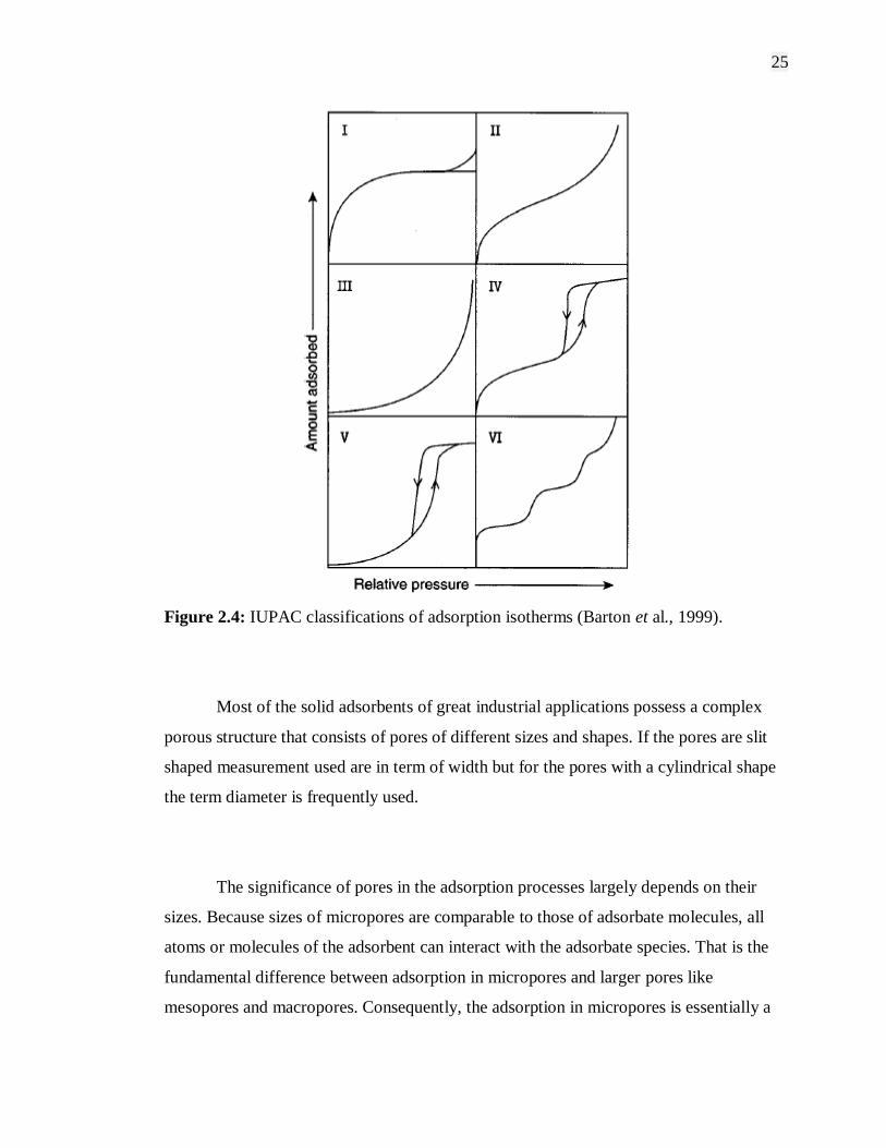
The IUPAC classification of adsorption isotherms is illustrated in Figure 2.4 The
six types of isotherm are characteristic of adsorbents that are microporous (type I),
nonporous or macroporous (types II, III, and VI) or mesoporous (types IV and V). The
differences between types II and III isotherms and between types IV and V isotherms
arise from the relative strengths of the fluid-solid and fluid-fluid attractive interactions:
types II and IV are associated with stronger fluid-solid interactions and types III and V
are associated with weaker fluid-solid interactions. The hysteresis loops usually
exhibited by types IV and V isotherms are associated with capillary condensation in the
mesopores. The type VI isotherm represents adsorption on nonporous or macroporous
solids where stepwise multilayer adsorption occurs (Kruk et al., 1999; Sing, 2001;
Barton et al., 1999; Ustinov et al., 2005).
25
Figure 2.4: IUPAC classifications of adsorption isotherms (Barton et al., 1999).
Most of the solid adsorbents of great industrial applications possess a complex
porous structure that consists of pores of different sizes and shapes. If the pores are slit
shaped measurement used are in term of width but for the pores with a cylindrical shape
the term diameter is frequently used.
The significance of pores in the adsorption processes largely depends on their
sizes. Because sizes of micropores are comparable to those of adsorbate molecules, all
atoms or molecules of the adsorbent can interact with the adsorbate species. That is the
fundamental difference between adsorption in micropores and larger pores like
mesopores and macropores. Consequently, the adsorption in micropores is essentially a
26
pore-filling process in which their volume is the main controlling factor (Everett, 1998;
Dabrowski, 2001). Thus, as the essential parameter characterizing micropores is their
volume usually referred to a unit mass of the solid and characteristics of their sizes. This
characteristic is expressed by the micropore distribution function evaluated mainly from
the low concentration adsorption data.
In the case of mesopores whose walls are formed by a great number of adsorbent
atoms or molecules, the boundary of interphases has a distinct physical meaning. That
means that the adsorbent surface area has also a physical meaning. In macropores the
action of adsorption forces does not occur throughout their void volume but at a close
distance from their walls. Therefore, the monolayer and multilayer adsorption takes
place successively on the surface of mesopores, and their final fill proceeds according to
the mechanism of capillary adsorbate condensation. Therefore, the basic parameters
characterizing mesopores are:
Specific surface area
Pore volume
Pore size or pore volume distribution.
Mesopores, like macropores, play an essential role in the transport of adsorbate
molecules inside the micropore volume. The mechanism of adsorption on the surface of
macropores does not differ from that on flat surfaces. The specific surface area of
macroporous solids is very small, that is why adsorption on this surface is usually
neglected. The capillary adsorbate condensation does not occur in macropores (Sing,
1998; Jaroniec et al., 2001; Dabrowski, 2001).
27
2.2.4 Adsorption Mechanism by Porous Adsorbents
2.2.4.1 Physisorption by Microporous Adsorbents
In the IUPAC classification of pore size, the upper limit of the micropore width
was placed at approximately 2 nm. It turns out that this limiting width is somewhat
arbitrary since the mechanism of pore filling is not determined by pore width alone.
The high p/p0 plateau of a well-defined Type I isotherm always extends over a
wide multilayer range. The great majority of Type I isotherms can be attributed to
micropore filling, but there are a few systems like butanol on alumina with which a form
of „gas phase autophobicity‟ inhibits the development of the multilayer. This behavior is
not possible with simple adsorptive molecules such as Ar, Kr, N , O and etc. Or even
with alkanes and other larger molecules of low polarity. With these adsorptives, the low
multilayer slope is a direct consequence of a small external area (Dabrowski, 2001;
Sing, 1998).
It is now apparent that Type I isotherms can be broadly divided into two groups.
Ultramicroporous carbons and molecular sieve zeolites exhibit high adsorption affinity,
their isotherms generally having a high degree of rectangularity with the plateau
approached at very low p/p0. The second group of Type I isotherms are
„supermicroporous‟ activated carbons and oxide xerogels which have wider pores. In
this case, the initial part of the isotherm is less steep and the approach to the plateau
more gradual. However, this difference in isotherm shape is not really controlled by the
absolute pore width, but it is dependent on the pore width and geometry in relation to
the size, shape and electronic character of the adsorptive molecules (Barton et al., 1999;
Dabrowski, 2001; Sing, 1998).
28
The micropores in activated carbons tend to be slit-shaped. In the
ultramicropores of this shape there is a significant overlap of adsorption forces provided
that the pore widths are not much larger than two molecular diameters. This is
manifested in the form of enhanced adsorption energies, which are responsible for the
steepness of the isotherm at low p/p0. This process has been termed „primary micropore
filling‟. Supermicropores in the range of approximately 2 to 5 molecular diameters are
filled by a combination of surface coverage at low p/p0 and a cooperative process or
quasi-multilayer adsorption at higher p/p0 (up to 0.2). Since it involves two overlapping
stages, supermicropore filling is not a first order transition, as in the case of capillary
condensation (Kruk et al., 1999; Sing, 1998).
2.2.4.2 Physisorption by Mesoporous Adsorbents
The characteristic shape of a Type IV isotherm is the result of surface coverage
of the mesopore walls followed by pore filling. The onset of capillary condensation (the
pore filling process) is indicated by an upward departure of the isotherm from the
multilayer Type II isotherm for the same gas-solid system. The plateau at higher p/p0 is
attained when the mesopore filling is complete (Barton et al., 1999; Sing, 1998).
If the Kelvin equation is used to evaluate the mesopore size, it is necessarily
assumed that a simple relationship relates the meniscus curvature to the pore shape and
size. Thus, if the pores are cylindrical, the meniscus shape is hemispherical; but if the
pores are slit-shaped, the meniscus becomes hemicylindrical. Other assumptions
involved in the computation of the mesopore size distribution are that the pores are rigid
and that a standard multilayer correction curve can be applied. To obtain the mesopore
volume from the amount adsorbed at the plateau, the condensate is assumed to have the
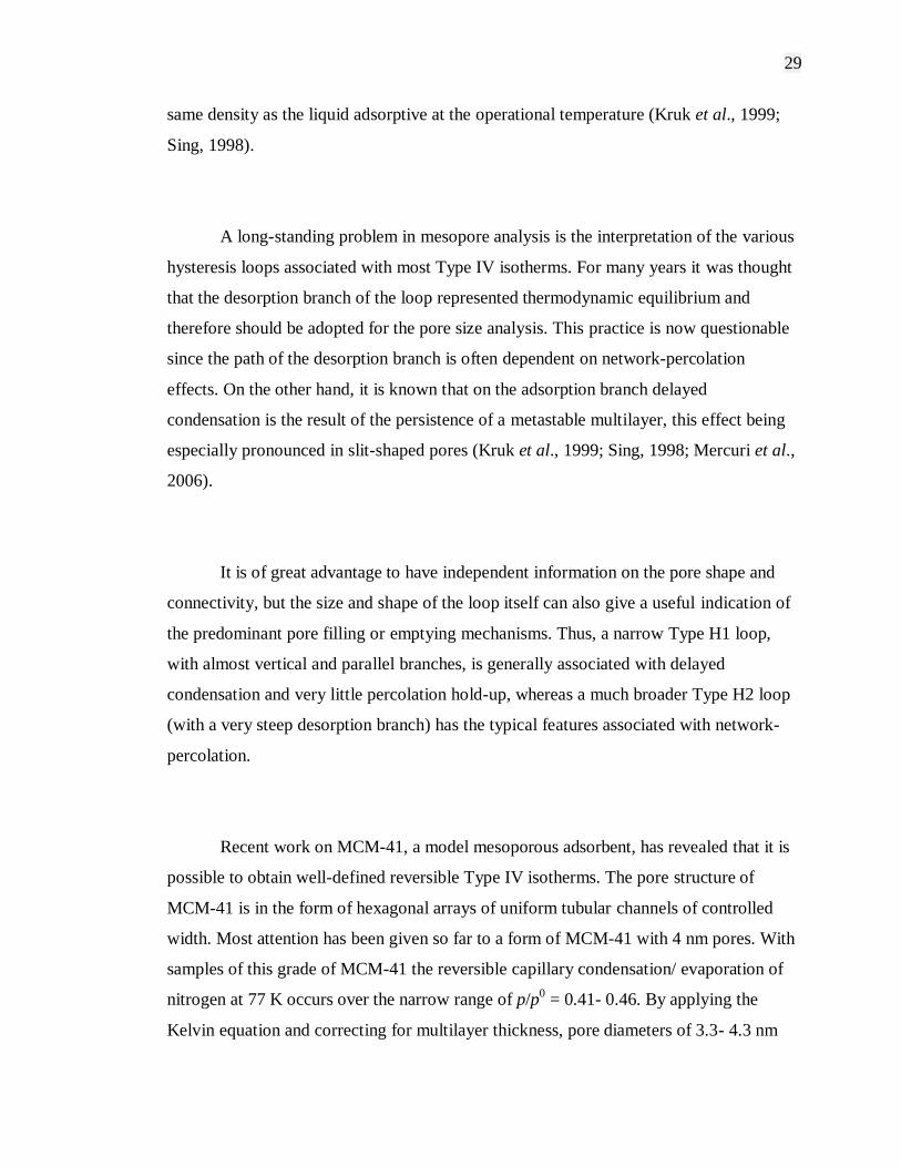
29
same density as the liquid adsorptive at the operational temperature (Kruk et al., 1999;
Sing, 1998).
A long-standing problem in mesopore analysis is the interpretation of the various
hysteresis loops associated with most Type IV isotherms. For many years it was thought
that the desorption branch of the loop represented thermodynamic equilibrium and
therefore should be adopted for the pore size analysis. This practice is now questionable
since the path of the desorption branch is often dependent on network-percolation
effects. On the other hand, it is known that on the adsorption branch delayed
condensation is the result of the persistence of a metastable multilayer, this effect being
especially pronounced in slit-shaped pores (Kruk et al., 1999; Sing, 1998; Mercuri et al.,
2006).
It is of great advantage to have independent information on the pore shape and
connectivity, but the size and shape of the loop itself can also give a useful indication of
the predominant pore filling or emptying mechanisms. Thus, a narrow Type H1 loop,
with almost vertical and parallel branches, is generally associated with delayed
condensation and very little percolation hold-up, whereas a much broader Type H2 loop
(with a very steep desorption branch) has the typical features associated with network-
percolation.
Recent work on MCM-41, a model mesoporous adsorbent, has revealed that it is
possible to obtain well-defined reversible Type IV isotherms. The pore structure of
MCM-41 is in the form of hexagonal arrays of uniform tubular channels of controlled
width. Most attention has been given so far to a form of MCM-41 with 4 nm pores. With
samples of this grade of MCM-41 the reversible capillary condensation/ evaporation of
nitrogen at 77 K occurs over the narrow range of p/p0 = 0.41- 0.46. By applying the
Kelvin equation and correcting for multilayer thickness, pore diameters of 3.3- 4.3 nm

30
can be obtain, which agrees well with a mean value of approximately 4 nm derived from
the volume/ surface ratio (Kruk et al., 1999; Mercuri et al., 2006; Sing, 1998). A
number of other adsorptives such as argon, oxygen, carbon dioxide, sulfur dioxide and
various alcohols have been found to give Type H1 hysteresis loops with the 4 nm
MCM-41. In another investigation, it was found that the carbon tetrachloride isotherms
determined at temperatures between 273 and 303 K on a 3.4 nm pure silica form of
MCM-41 exhibited steep and very narrow hysteresis loops, whereas the corresponding
isotherm at 323 K was completely reversible (Beck and Vartuli, 1996; Sing, 1998).
According to Sing, 1998, when they are confined to very narrow ranges of p/p0,
the reversible pore-filling steps appear to be equivalent to first order phase
transformations, the p/p0 being dependent on the adsorptive and the temperature. It
seems significant that for a given adsorptive the characteristic p/p0 is remarkably close
to the lower limit of closure of the hysteresis loop (the limiting chemical potential
controlling the stability of the capillary condensate). As a conclusion, the reversible
stepwise filling of the mesopores in MCM-41 is due to:
(i) The absence of pore blocking effects.
(ii) The tubular pore shape.
(iii) The particular range of its narrow pore size distribution in relation to the
temperature and properties of the adsorptive.
31
2.2.5 Adsorption Controlling Parameters
Since the discovery of porous materials, the adsorption study between solid and
gas has advanced to a new level. There had been numerous studies on adsorption
controlling parameters and can be concluded to the following factors:
(i) Nature of adsorbent and adsorbate.
(ii) Surface area of the adsorbent.
(iii) Pressure.
(iv) Temperature.
The nature of adsorbent and adsorbate show significant effect on the amount of
gas (adsorbate) adsorbed into/ onto adsorbent. Easily liquefy gases such as SO2, NH3,
HCl and CO2 adsorbed more readily than permanent gases like H2, N2 and O2 which do
not liquefy easily. This is the result of Van der Waals or molecular forces of the easily
liquefy gases which is much greater than permanent gases. Different type of adsorbents
adsorbed different amounts of gas. Vice versa, different type of gases (adsorbate)
adsorbed onto adsorbent in a different amounts depends on the nature of the adsorbates
such as molecular weight, polarity, molecule size, shape and other physical and
chemical properties (Dabrowski, 2001; Chhatwal and Mehra, 1974).
Adsorption refers to the condensation of gases on free surfaces as opposed to
absorption where molecules penetrate into the mass of the absorbent. This shows how
much important of high surface area in adsorption. A large specific surface area is
preferable for providing large adsorption capacity. However, the creation of high
internal surface area in a specific volume gives rise to a much larger numbers of small
sized pores between adsorption surfaces. The size of the micropores determines the
accessibility of adsorbate molecules to the internal adsorption surface, therefore the pore
size distribution of micropores is another important property for characterizing
32
adsorptivity of adsorbents. Porous materials such as zeolite, mesoporous molecular
sieves and carbon molecular sieves can be specifically synthesis with precise pore size
distribution and hence can be tailored for a particular separation (Barton et al., 1999;
Beck and Vartuli, 1996).
Adsorption capacity also depends on the pressure of the gas in a certain
confinement in the adsorption process. Adsorption of gas basically follow Le Chatelier‟s
principle which stated that with the decrease of pressure, the magnitude of adsorption
also decrease and vice versa. Besides that, Le Chatelier‟s principle can also be apply for
temperature effects on adsorption. However, the principle is a bit different whereas, the
decrease in temperature will result in increase of adsorption magnitude and vice versa.
Physical adsorption (physisorption) is very effective particularly at a temperature close
to the critical temperature of a given gas. Meanwhile, chemical adsorption
(chemisorption) occurs usually at temperatures much higher than the critical temperature
(Dabrowski, 2001; Sing, 1998; Chhatwal and Mehra, 1974).
2.3 Adsorbents
Most solid adsorbents for industrial applications possess a complex porous
structure that consists of different sizes and shapes. If the pores are slit shaped, their
width is consider as the size. However, for pores with cylindrical shape the term
diameter is frequently used.
Adsorbents or porous materials are characterized in terms of pore sizes derived
from gas sorption data. Through IUPAC conventions, classification of pore sizes and
33
gas sorption isotherms reflect the relationship between porosity and sorption
(Dabrowski, 2001; Barton et al., 1999). Pores are classified according to pore diameter
as follows:
Micropores diameters less than 2 nm;
Mesoporous diameters between 2 and 50 nm;
Macroporous diameters more than 50 nm.
2.3.1 Microporous Materials
In the IUPAC classification of pore size, the upper limit of the micropore width
was placed at approximately 2 nm. Any structure below 2 nm in pore size are considered
microporous materials such as zeolite A, zeolite Y, ZSM-5, AlPO4-11, AlPO4-5, VPI-5,
cloverite and others which mostly are from zeolite type of framework materials. Zeolites
occur in nature and have been known for almost 250 years as aluminosilicate minerals.
Examples are faujasite, mordenite, offretite, ferrierite, erionite and chabazite. Today,
these and other zeolite structures are of great interest in catalysis and other applications,
yet their naturally occurring forms are of limited value, because:
i) they almost always contain undesired impurity phases,
ii) their chemical composition varies from one deposit to another and even
from one stratum to another in the same deposit,
iii) nature did not optimize their properties for catalytic applications.
Zeolite was originally discovered in the 18th century (1756) by a Swedish
mineralogist, Cronstedt, who describes the zeolite behavior under fast heating
34
conditions, when the zeolite minerals seem to boil because of the fast water loss. The
word derives from two Greek words zeo and lithos, which means “stone that boils”.
Typically, zeolites are hydrated, porous crystalline aluminosilicates. The framework is
an assemblage of SiO4 and AlO4 tetrahedral joined together by sharing oxygen atoms
(Ghobarkar et al., 1999; Weitkamp, 2000).
2.3.1.1 Classification of Zeolites
The term "molecular sieve" is used to describe a class of materials that exhibit
selective sorption properties, for instance that are able to separate components of a
mixture on the basis of molecular size and shape. The term molecular sieve is used to
describe microporous crystalline materials such as aluminosilicates (zeolites), silica
molecular sieves, aluminoposphates and related materials.
The extraordinary properties of zeolites are caused by their crystal lattice.
Therefore, a proper classification starts from the 3-dimensional bonding of the
tetrahedrally coordinated framework cations. Today about 800 different zeolites are
known which can be classified by 119 different zeolite structure types. These structure
types are described by a three letter code. Only about l/4 of them are naturally occurring,
the others are synthetic. Instead of using the unit cell of the respective zeolite for
description, which is only specific for the zeolite type, secondary building units (SBU‟s)
consisting of different arrangements of tetrahedra (primary building units) are used. The
SBUs are, however, only building elements of the zeolite unit cell. Different SBUs can
be used for the classification of a zeolite (Ghobarkar et al., 1999; Weitkamp, 2000).

35
The topology of the zeolite framework is given by a unique three-letter code
which is not related to the composition of the material. Thus, ZSM-5 and silicalite-1 are
materials with MFI topology. Silicalite-1 is a pure silica analogue of ZSM-5 (generally,
an MFI type material is regarded as ZSM-5 when there is more than one aluminum per
unit cell, for example a SiO2/Al2O3 ratio less than 190) and strictly it cannot be
considered as a zeolite but rather as a silica molecular sieve. The MFI structure is built
up by 5-1 secondary building units (SBU; the smallest number of TO4 units, where T is
Si or Al, from which zeolite topology is built) which are link together to form chains as
shown in Figure 2.5 and the interconnection of these chains leads to the formation of the
channel system in the structure. The MFI structure has a three dimensional pore system
consisting of sinusoidal 10-ring channels (5.1 x 5.5 Å) and intersecting straight 10-ring
channels (5.3 x 5.6 Å) (Weitkamp, 2000; Han et al., 2005)
Figure 2.5: A 5-1 secondary building unit and the MFI structure (Weitkamp, 2000).
36
2.3.1.2 Structure and Framework of Zeolites
The elementary building units of zeolites are SiO and AlO tetrahedra. Adjacent
tetrahedra are linked at their corners via a common oxygen atom, and this result in an
inorganic macromolecule with a structurally distinct three-dimensional framework. It is
evident from this building principle that the net formula of the tetrahedra is SiO and
AlO2- . The framework of a zeolite contains channels, and channel interintersections
and/or cages with dimensions from 0.2 to 1 nm. Inside these voids are water molecules
and small cations which compensate the negative framework charge.
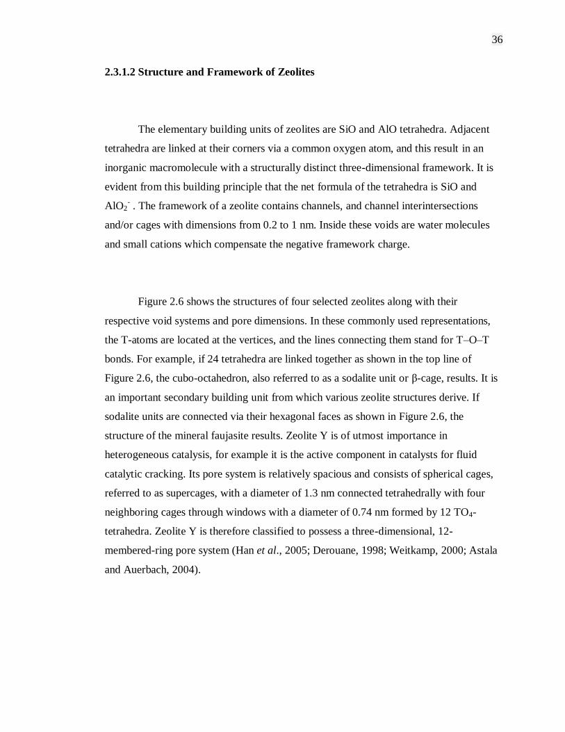
Figure 2.6 shows the structures of four selected zeolites along with their
respective void systems and pore dimensions. In these commonly used representations,
the T-atoms are located at the vertices, and the lines connecting them stand for T–O–T
bonds. For example, if 24 tetrahedra are linked together as shown in the top line of
Figure 2.6, the cubo-octahedron, also referred to as a sodalite unit or β-cage, results. It is
an important secondary building unit from which various zeolite structures derive. If
sodalite units are connected via their hexagonal faces as shown in Figure 2.6, the
structure of the mineral faujasite results. Zeolite Y is of utmost importance in
heterogeneous catalysis, for example it is the active component in catalysts for fluid
catalytic cracking. Its pore system is relatively spacious and consists of spherical cages,
referred to as supercages, with a diameter of 1.3 nm connected tetrahedrally with four
neighboring cages through windows with a diameter of 0.74 nm formed by 12 TO4-
tetrahedra. Zeolite Y is therefore classified to possess a three-dimensional, 12-
membered-ring pore system (Han et al., 2005; Derouane, 1998; Weitkamp, 2000; Astala
and Auerbach, 2004).

37
Figure 2.6: Structures of four selected zeolites (from top to bottom: faujasite or zeolites
X, Y; zeolite ZSM-12; zeolite ZSM-5 or silicalite-1; zeolite Theta-1 or ZSM-22) and
their micropore systems and dimensions (Weitkamp, 2000).
2.3.2 Mesoporous Materials
Porous materials have attracted the attention of chemists and materials scientists
due to commercial interest in their application in chemical separations and
heterogeneous catalysis as well as scientific interest in the challenges posed by their
synthesis, processing, and characterization. Application of basic scientific principles to
the key technological issues involved has been difficult, however, and much more
progress has been achieved in tailoring porous materials through manipulation of
processing parameters than through understanding of the chemical and physical
mechanisms that influence porosity. As a result, the tailoring of porous materials has
proceeded largely in an empirical fashion rather than by design (Barton et al., 1999).
38
The discovery of the first ordered (where the pores are ordered periodically),
mesoporous molecular sieves has sparked interest throughout the scientific community.
These materials, possessing pore sizes in the ~2-50 nm range, have a wide range of
potential applications including shape-selective catalysis and sorption of large organic
molecules, chromatographic separations, and uses as hosts to confine guest molecules
and atomic arrays. Several reviews on the general classification, properties, synthesis,
and potential applications of mesoporous materials have already been studied.
The rational design of structured, complex inorganic frameworks with pores
large enough to be used in the various applications awaited a viable synthetic approach.
Several years ago, such an approach was discovered, resulting in the synthesis of the
first members of an extensive family of silicate/aluminosilicate mesoporous molecular
sieves designated as M41S. An unusual mechanism for the formation of these materials,
known as liquid crystal templating, in which supramolecular assemblies of cationic
alkyhrimethylammonium surfactants serve as components of the template for the
formation of these materials, was proposed to account for their formation (Zhao et al.,
1996; Mercuri et al., 2006; Barton et al., 1999; Beck and Vartuli, 1996; Kruk et al.,
1999).
The discovery of these new materials led to an extension of the structure
directing or templating concepts. That is, traditional zeolite synthesis typically involves
the crystallization of a silicate around a single molecule. These new materials extended
this single molecule concept making it possible to use a group of molecules like
micelles. In the formation of these mesoporous materials a highly unusual combination
of supramolecular cationic surfactant aggregates and anionic silicate species make up
the functional templating agents. The ability to tailor these surfactant assemblies so that
they can be used to design novel molecular sieve materials with engineered structure,
pore diameter, and composition has provided an excellent opportunity for further
advances in this area (Zhao et al., 1996; Beck and Vartuli, 1996; Barton et al., 1999).
39
2.3.2.1 Formation Mechanism of Mesoporous Materials
A new class of mesoporous molecular sieves, M41S, has been discovered by
extending the concept of zeolite templating with small organic molecules to longer chain
surfactant molecules. Rather than individual molecular directing agents participating in
the ordering of the reagents to form the porous material, assemblies of molecules,
dictated by solution energetics, are responsible for the formation of these pore systems.
This supramolecular directing concept is illustrated in Figure 2.7 has led to a family of
materials whose structure, composition, and pore size can be tailored during synthesis
by variation of the reactant stoichiometry, nature of the surfactant molecule, or by
postsynthesis functionalization techniques (Zhao et al., 1996; Boger et al., 1997; Barton
et al., 1999; Beck and Vartuli, 1996).
Figure 2.7: The formation of microporous molecular sieves using individual small alkyl
chain length quaternary directing agents (top) and the formation of mesoporous
molecular sieves using long alkyl chain length quaternary directing agents (bottom)
(Barton et al., 1999).

40
The formation mechanism of this mesoporous family of molecular sieves is
dictated by two features. The first is the dynamics of surfactant molecules to form
molecular assemblies which lead to micelle and, ultimately, liquid crystal formation.
The second is the ability of the inorganic oxide to undergo condensation reactions to
form extended thermally stable structures. The initial discovery involved the formation
of silicates using alkyltrimethylammonium cationic surfactants in a basic medium.
Subsequent efforts have shown these structures can also be formed in acid media and by
using neutral normal amines, nonionic surfactants, and dialkyldimethylammonium
cationic surfactants. In addition, several mechanistic studies have expanded the initial
pathway studies to a more generalized view of an organic/inorganic charge balance
driving force for the formation of these structures (Zhao et al., 1996; Zhao et al., 2000;
Barton et al., 1999).
Initial speculation on the mechanistic pathway shown in Figure 2.8, leading to
the formation of these mesoporous materials considered two possibilities. The first was
that the surfactant molecules organize independently of the inorganic silicate
crystallization, and that the siliceous framework polymerizes around these preformed
surfactant aggregates. The second was that silicate anions in solution, by virtue of their
charge balance with the cationic surfactants, play an intimate role in directing the
formation of the supramolecular surfactant arrays. In either ease a liquid crystal template
is implicated.
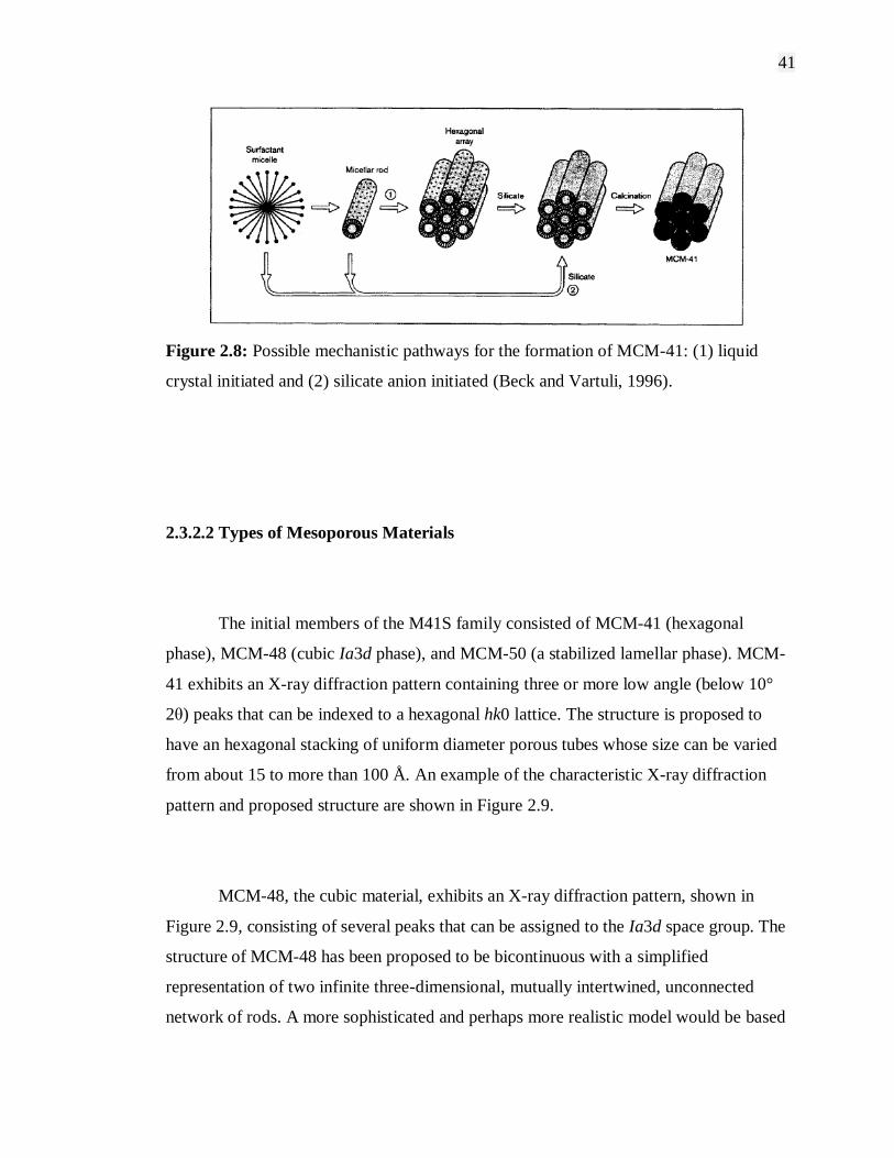
41
Figure 2.8: Possible mechanistic pathways for the formation of MCM-41: (1) liquid
crystal initiated and (2) silicate anion initiated (Beck and Vartuli, 1996).
2.3.2.2 Types of Mesoporous Materials
The initial members of the M41S family consisted of MCM-41 (hexagonal
phase), MCM-48 (cubic Ia3d phase), and MCM-50 (a stabilized lamellar phase). MCM-
41 exhibits an X-ray diffraction pattern containing three or more low angle (below 10°
2θ) peaks that can be indexed to a hexagonal hk0 lattice. The structure is proposed to
have an hexagonal stacking of uniform diameter porous tubes whose size can be varied
from about 15 to more than 100 Å. An example of the characteristic X-ray diffraction
pattern and proposed structure are shown in Figure 2.9.
MCM-48, the cubic material, exhibits an X-ray diffraction pattern, shown in
Figure 2.9, consisting of several peaks that can be assigned to the Ia3d space group. The
structure of MCM-48 has been proposed to be bicontinuous with a simplified
representation of two infinite three-dimensional, mutually intertwined, unconnected
network of rods. A more sophisticated and perhaps more realistic model would be based
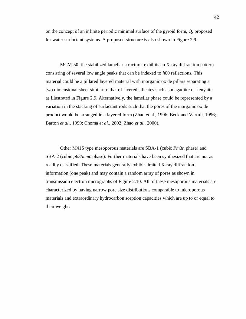
42
on the concept of an infinite periodic minimal surface of the gyroid form, Q, proposed
for water surfactant systems. A proposed structure is also shown in Figure 2.9.
MCM-50, the stabilized lamellar structure, exhibits an X-ray diffraction pattern
consisting of several low angle peaks that can be indexed to h00 reflections. This
material could be a pillared layered material with inorganic oxide pillars separating a
two dimensional sheet similar to that of layered silicates such as magadiite or kenyaite
as illustrated in Figure 2.9. Alternatively, the lamellar phase could be represented by a
variation in the stacking of surfactant rods such that the pores of the inorganic oxide
product would be arranged in a layered form (Zhao et al., 1996; Beck and Vartuli, 1996;
Barton et al., 1999; Choma et al., 2002; Zhao et al., 2000).
Other M41S type mesoporous materials are SBA-1 (cubic Pm3n phase) and
SBA-2 (cubic p63/mmc phase). Further materials have been synthesized that are not as
readily classified. These materials generally exhibit limited X-ray diffraction
information (one peak) and may contain a random array of pores as shown in
transmission electron micrographs of Figure 2.10. All of these mesoporous materials are
characterized by having narrow pore size distributions comparable to microporous
materials and extraordinary hydrocarbon sorption capacities which are up to or equal to
their weight.
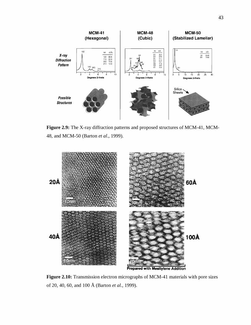
43
Figure 2.9: The X-ray diffraction patterns and proposed structures of MCM-41, MCM-
48, and MCM-50 (Barton et al., 1999).
Figure 2.10: Transmission electron micrographs of MCM-41 materials with pore sizes
of 20, 40, 60, and 100 Å (Barton et al., 1999).
44
The initial forms of the M41S family were synthesized as silicates and
aluminosilicates. Subsequent synthesis efforts have produced materials having
heteroatom substitution as well as nonsiliceous products. The initial nonsiliceous
materials included oxides of W, Fe, Pb, Mo and Sb. Many of these materials exhibited
very poor thermal stability and upon the removal of the template, the structures
collapsed. Mesoporous zirconia and titania materials have been prepared but only
exhibit satisfactory thermal stability and thus are believed to be composed of extended
and complete oxide nets of the elements (Zhao et al., 1996; Barton et al., 1999; Zhao et
al., 2000).
2.3.2.3 Application of Mesoporous Materials
Potential applications of these mesoporous molecular sieves are as exciting as
their discovery. In earlier years, mesoporous materials were examined for applications
relating to their large pore volumes. Such applications including the use of mesoporous
adsorbents for removal of volatile organic compound (VOC) in the industrial setting. In
pursuit of such goals, the behavior of a variety of adsorbates has now been
comprehensive. Almost all reported data agree that mesoporous materials have large
accessible internal pore volumes which can be filled at pressures appropriate with the
pore size (Zhao et al., 2001; Beck and Vartuli, 1996).
The sorptive properties of MCM-41, the hexagonal member of the M41S family
of mesoporous silicates, have been extensively characterized using a variety of
adsorbates. Some recent highlights include careful comparison of adsorption of a series
of gases in a single sample of MCM-41. This work showed that the type of isotherm
observed is highly dependent upon a number of factors including the material
45
composition, pore size, and nature of the adsorbent. Current study of adsorption
isotherms on gases like argon, nitrogen and oxygen using well characterized MCM-41
sample confirm that MCM-41 has a narrow pore size distribution and exhibits
extraordinary pore volume compared to classical microporous materials (Zhao et al.,
1996; Dabrowski, 2001; Barton et al., 1999; Beck and Vartuli, 1996).
Despite the impressive adsorption capacities of these materials, their type IV
isotherm behavior requires the adsorbate, in the gas phase, to be at high partial pressure.
However, by contrast in most industrial application, for example VOC uptake, where
adsorption at low partial pressures (type I isotherms) is required and poses constraint to
the mesoporous materials application. Industrial applications which utilize mesoporous
materials are catalytic processes, mini-reactors for electron transfer reaction, as a host
for quantum confinement, molecular wires and shape-selective polymerization (Beck
and Vartuli, 1996).
2.3.3 Modification of Porous Materials
One of the unique features of the M41S family materials is the ability to tailor
pore size. The pore size can be varied from about 15 Å to more than 100 Å by varying
the length of the alkyl chain of the template molecule or by the use of supporting
solubilized molecules. A series of transmission electron micrographs of MCM-41
materials having pore diameters from 20 to 100 Å is shown in Figure 2.8. The approach
taken to varying mesopore size in a regular, systematic fashion shows the contrast to the
inability to accomplish such goals for traditional microporous zeolitic materials (Zhao et
al., 1996; Barton et al., 1999; Kumar et al., 2001; Zhao et al., 2001).
46
Mobil catalytic materials of number 41 or MCM-41 belongs to the family of
mesoporous molecular sieves discovered in the 1990s. These highly ordered pore
systems with tunable pore sizes, large specific surface areas and pore volumes, and high
density of surface silanols provide excellent opportunities for inclusion chemistry. A
large number of functionalizing entities including both organic and inorganic
components have been introduced into the channels to generate catalysts, adsorbents,
and to improve the hydrothermal and mechanical stabilities.
All these modifications/ functionalizations can be achieved either by post-
modification or by in situ synthesis. By post-modification, it is possible to
sophisticatedly design and synthesize custom-tailored materials. For example, post-
silylation can drastically improve the hydrothermal stability and mechanical stability of
MCM-41 materials due to enhanced surface hydrophobicity. Meanwhile, thiol-
functionalized MCM-41 adsorbents show a high adsorption efficiency of heavy metal
ions from water. Although the detailed chemical reaction mechanism of post-
modification has not been fully understood, it is believed that surface silanols serve as
reactive sites and can be replaced by other components which act as modifiers. In such a
way, a monolayer of a given modifier is attached to the surfaces of MCM-41, resulting
in the changes of not only structural properties such as pore size, pore volume, and
surface area, but also surface properties such as hydrophobicity/ hydrophilicity, polarity,
acidity, afinity, etc (Zhao et al., 1996; Zhao et al., 2000; Zhao et al., 2001; Barton et al.,
1999; Beck and Vartuli, 1996; Choma et al., 2002).
Another method which is considered new but has become useful, versatile,
simple and efficient method recently known as freeze drying method. This method has
been used widely to obtain porous ceramic materials or granules. Through this method,
it is possible to control the porosity by varying a number of parameters and to improve
the sinterability of the materials, reducing the temperature of sintering and decreasing
the shrinkage and defects. The freeze drying method consists of a rapid freezing in small
47
droplets of salt solution which contain the desired cation or cations, maintaining the
chemical homogeneity. Subsequent sublimation of ice under vacuum conditions leads to
porous spheres of the anhydrous salt with a high surface area, which consolidates during
the calcination process needed to remove the anion and grow the oxide nanoparticles.
Freeze drying method is preferred for this study as the amines used for modification
have moderate boiling temperatures. This method also allows the synthesis of a variety
of powders with accurate control of the composition while evidently maintain the
structure of support materials (Tallon et al., 2006a; Tallon et al., 2006b; Lee et al.,
2006).
2.4 Summary
Porous materials such as microporous and mesoporous materials have high
potential in a wide range of application including catalytic, adsorption processes,
encapsulation technology, gas storage, separation and nanoparticles technology. The
unique properties of these materials such as highly ordered pore structure, high surface
area, tunable pore size or the ability to tailor framework, high hydrothermal and
mechanical stabilities, large pore volumes and high density of surface silanol have make
these materials superior compare to other materials. All these advantages lead to
research and development interest in improving these materials by modifying using
various types of components organic and inorganic. The importances of amine modified
supporting materials are outlined in the review as well as the modification method and
applications. Attentions of the literature have been made for the separation of carbon
dioxide from natural gas using solid adsorbent through adsorption process.
48
Through literature study, the removal of carbon dioxide from crude natural gas is
accomplished by gas-liquid absorption processes using aqueous solutions of
alkanolamines. However, this gas absorption process is highly energy intensive for
regeneration of the solvents and is also plagued by corrosion problems. The
development of regenerable solid sorbents with high selectivities for carbon dioxide and
high adsorption capacities is a potential alternative for natural gas purification because
such materials are more environmentally benign and easier to handle in solid form as
well as able to regenerate under mild condition thus more energy efficient. Silica and
ordered mesoporous silica are ideal solid supports for active functions because of their
large surface area and well defined pore structures. More importantly, the hydroxyl
groups on their surfaces are important for many surface phenomena, such as gas
adsorption, surface modification and wetting. Because of the high concentrations of
surface silanol groups (SiOH), silica and ordered mesoporous silicas such as MCM-41
and SBA-15 are widely used for surface modification for instance, grafting of functional
groups like amines onto the pore walls of the silica via silylation reactions between the
surface silanol groups and the grafting material.
CHAPTER 3
MATERIALS AND METHODS
3.1 Materials
3.1.1 Chemicals
The general chemicals needed for the synthesis of mesoporous adsorbents are
shown in Table 3.1. All chemicals which required dilution and glassware required
rinsing were from freshly deionised water from Purite Select AN HP40 (Purite Ltd,
England) with resistivity ~15 – 16 M cm. Amines used were monoethanolamine
(Merck), diethanolamine (Merck), triethanolamine (BDH), methyl diethanolamine
(Merck) and polyethylenimine (Fluka) for modification of support materials. High
purity commercial chemical such as cetyltrimethylammonium bromide (BDH),
tetraethyl orthosilicate (Merck), ammonium hydroxide (Merck), hydrochloric acid
(Merck) and Pluronic P123 (BASF) were used to synthesis mesoporous supports.
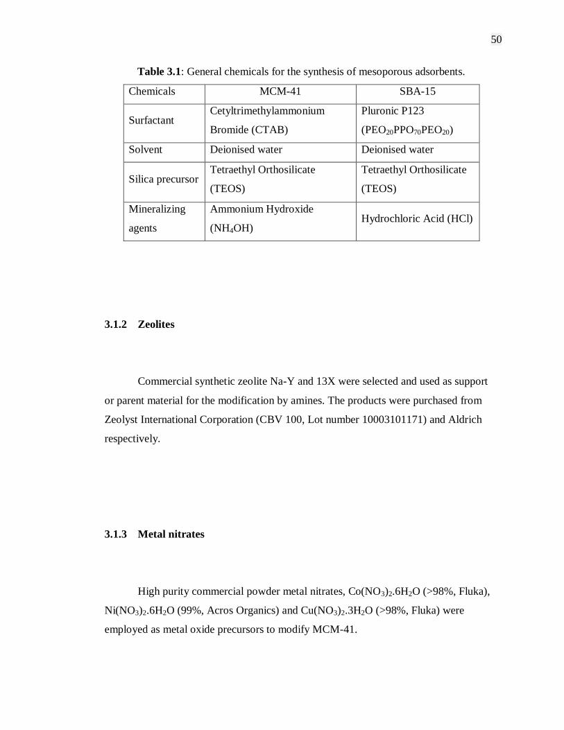
50
Table 3.1: General chemicals for the synthesis of mesoporous adsorbents.
Chemicals MCM-41 SBA-15
Surfactant Cetyltrimethylammonium
Bromide (CTAB)
Pluronic P123
(PEO20PPO70PEO20)
Solvent Deionised water Deionised water
Silica precursor Tetraethyl Orthosilicate
(TEOS)
Tetraethyl Orthosilicate
(TEOS)
Mineralizing
agents
Ammonium Hydroxide
(NH4OH) Hydrochloric Acid (HCl)
3.1.2 Zeolites
Commercial synthetic zeolite Na-Y and 13X were selected and used as support
or parent material for the modification by amines. The products were purchased from
Zeolyst International Corporation (CBV 100, Lot number 10003101171) and Aldrich
respectively.
3.1.3 Metal nitrates
High purity commercial powder metal nitrates, Co(NO3)2.6H2O (>98%, Fluka),
Ni(NO3)2.6H2O (99%, Acros Organics) and Cu(NO3)2.3H2O (>98%, Fluka) were
employed as metal oxide precursors to modify MCM-41.
51
3.1.4 Gases
Linde Gas Singapore PTE LTD supplied all gases used in this study. The
specifications of the gases are as follow: Carbon dioxide (high purity grade, 99.995%),
nitrogen (high purity grade, 99.995%) and purified argon (high purity grade, 99.999%).
3.2 Experimental Procedures
3.2.1 Preparation of Adsorbents
Many preparation methods have been developed by researchers for the synthesis
of MCM-41 and SBA-15 (Xu et al., 2003; Vartuli et al., 2001; Klimova et al., 2006;
Fulvio et al., 2005). General flow sheet of the procedures adopted is shown in Figure
3.1.

52
Figure 3.1: General experimental flow sheet.
Mix and stir solution Surfactant Mineralizing
agent
Silica
Precursor
Homogenize
Solution
Ageing
Filtration
Drying
Calcination
Characterization
53
3.2.1.1 MCM-41 Preparation
MCM-41 was synthesized according to standard methods in literatures (Kumar
et al., 2001; Xu et al., 2003; Hadi Nur et al., 2004; Vartuli et al., 2001; Zhao et al.,
1996). Synthesizing of MCM-41 began by dissolving 2.4g CTAB in 120g deionised
water and the solution is stirred to form homogeneous and clear solution. Then, 8ml
ammonium hydroxide was added into the solution and stirred for 5 min after which
10ml of TEOS was added into the solution. The solution was stirred overnight. Then,
the solution was transfer into a container and put in oven at 100ºC for 2 days. After that,
pH control was done at 10.2 each day until stable (2-3 days). The final product was
filtered and washed with deionised water. Then, the sample was spread onto a plate and
dried in oven at 100ºC for 24 hours. Calcination was performed at 550 0C for 5 hours
3.2.1.2 SBA-15 Preparation
Method for synthesizing of SBA-15 was in accordance to literatures reviewed
(Klimova et al., 2006; Fulvio et al., 2005; Mirji et al., 2006; Luan et al., 2005;
Srivastava et al., 2006; Andreza and Edesia, 2005). 4.0 g of Pluronic P123 was
dissolved in 30ml of deionised water. Then, 120ml of 2.0 M HCl was added into the
solution and stirred at room temperature for 2 hours. The resulting solution was then
transferred into a container and stirred at 40ºC. After that, 8.5g of TEOS was added drop
by drop into the solution while stirring for 30 minutes. Then, slowing down the stirring
rate to around 120 rpm and stirred for another 20 hours at the same temperature. After
that, ageing of the solution was done in an oven at 100ºC for 48 hours without stirring.
54
The final product was filtered, washed with deionised water and dried for 24 hours at
80ºC. Finally, the calcination was done at 550ºC for 5 hours under flowing air.
3.2.1.3 Metal modified MCM-41
Basically the preparation of metal modified MCM-41 is the same of preparing
pure MCM-41. Initially 2.4 grams of CTAB was mixed with 120 grams of deionized
water and the mixture was stirred until homogenous and clear solution was formed.
After about 2 hours, 8 mL of ammonium hydroxide was added and the mixture was
stirred for 5 minutes. Then 10 mL of TEOS and x grams (0.5 wt%) of respective metal
source (Copper Nitrate, Cobalt Nitrate or Nickel Nitrate) were added and the mixture
was stirred overnight. The mixture was then transferred into a teflon autoclave and aged
at 1000C for 2 to 3 days in the oven. pH control is done at 10.2 everyday by using acetic
acid until no significant changes in the pH value. The final product was then filtered and
washed thoroughly with deionised water. The filtered sample was transfered onto a plate
and dried in oven at 100ºC for 24 hours. Finally, the sample was calcined at 550ºC at a
rate of 1ºC /min for 5 hours.

55
3.2.2 Preparation of Modified Adsorbents
From previous study, modifying MCM-41 and SBA-15 using amines as
functional groups utilize the same conventional method which is known as wet
impregnation method (Xu et al., 2002; Xu et al., 2005). For MCM-41, methanol was
used as solvent to allow amine solution dissolved in the mixture before adding to the
calcined MCM-41. Then, the resultant slurry was stirred and dried at 70°C for 16 hours
under 700 mmHg vacuum. The same method was applied for SBA-15 with the only
different is that, the solvent used was toluene and the impregnated sample was heated at
150°C for 20 hours in a vacuum oven (Khatri et al., 2005; Gray et al., 2005).
Meanwhile, amine modified zeolites were prepared by reaction of raw zeolite with
amine at 200°C in an autoclave for 48 hours and some required calcination at high
temperature of up to 500°C for 2 hours (Han et al., 2005; Guo et al., 2006).
Through literature study, it can be observed that by using wet impregnation and
autoclave method, temperature of up to 200°C must be applied. This proves to be
inappropriate since the boiling point of most amine solutions are in a range of moderate
temperature. Therefore, this study attempts to introduce a new modification method
which is freeze drying method. In a typical preparation, the desired amount of amine
was mixed together with calculated amount of adsorbent and stirred for 2 hours. The
mixture was then solidified in a freezer for 24 hours and the crystal ice mixture finally
went through freeze drying process utilizing Freeze Dryer (Heto FD 4.0) to remove
water and obtained powder form product.

56
3.2.3 Characterization
3.2.3.1 Structural Characterization
The structural properties of modified adsorbents were characterized by powder
X-Ray Diffraction (XRD) using diffractometer (Bruker) with CuK radiation at a wave
length 1.5418 Å. XRD patterns were obtained with 40 kV and 40mA in the range of 2
= 0.6 - 10 for SBA-15 and 2 = 1.5 - 10 for MCM-41 with a scan speed of 0.02 per
second. (Gaydhankar et al., 2005; Klimova et al., 2006). Other than X-Ray
Diffractometer, Fourier Transform Infrared Spectrometer (FTIR) Perkin Elmer Model
2000 was used for identifying types of chemical bonds (functional groups) in the amine
modified adsorbents samples.
3.2.3.2 Physical Properties Characterization
Nitrogen adsorption and desorption isotherms were measured at 77K using
Quantachrome Autosorb to determine the physical properties such as pore diameter,
pore volume and surface area. Specific surface areas were calculated by conventional
Brunauer, Emmett, Teller (BET) method, pore volumes determined by nitrogen
adsorption at a relative pressure of 0.98 and pore size distributions from the desorption
isotherms by Barrett-Joyner-Halenda (BJH) method (Klimova et al., 2006; Kumar et al.,
2001; Zhao et al., 2000; Thommes et al., 2002; Gaydhankar et al., 2005; Fajula et al.,
2005).

57
3.2.4 Gas Adsorption Measurement
3.2.4.1 Thermal Gravimetric Analyzer (TGA)
The adsorption performance of the adsorbent was measured using thermal
gravimetric analyzer, Perkin Elmer Pyris 1 TGA. This instrument was used to measure
weight changes in sample as a function of either time or temperature. In a typical
adsorption measurement process, about 20 mg of the sample was used. Initially, heat
was supplied to the sample through furnace and the system was vacuum at the same
time for 24 hours to remove unwanted impurities and water vapor. The temperatures
used were varied from as low as 25˚C (without heating) up to 200˚C. Then, the
temperature was lowered and at the same time the target gas (carbon dioxide) will be
introduce for gas adsorption process. The temperature of adsorption process was set at
50˚C, however for further study the adsorption temperatures were differed from 25˚C
(room temperature) to as high as 75˚C. The temperature was held isotherm for
approximately 24 hours until equilibrium state was achieved. The carbon dioxide gas
used was 99.995% high purity grade and flowing through silica gel to further remove
moisture. The heating rate was set to 10˚C/min and cooling rate at 5˚C/min in order to
allow considerable time of adsorption. The adsorption capacity was evaluated from
weight changes of the samples in mg adsorbate/ g adsorbent. (Xu et al., 2003; Xu et al.,
2002; Zheng et al., 2005; Zhao et al., 2001).
58
3.2.4.2 Fourier Transform Infrared Spectroscopy (FTIR)
Fourier Transform Infrared Spectroscopy (FTIR) was used to study the
microscope behavior of molecules adsorbed on the adsorbents. Infrared studies had
been successfully used in studying the configuration and orientation of physisorbed and
chemisorbed species on an adsorbent surface (Rajesh et al., 2005; Zheng et al., 2005;
Rege and Yang, 2001).
A laboratory-made FTIR cell unit used in this study is illustrated in Figure 3.2.
The apparatus for FTIR measurement is made up of stainless steel equipped with a CaF2
window 25 mm in diameter in order to be used at 423.15 K under the pressure up to 276
kPa. CaF2 with 77, 000 – 900 cm-1
useful range has been chosen as window material
due to the high resistance to most acids and bases; does not fog; insoluble in water and
useful for high pressure work (Philippe et al., 2004a; Philippe et al., 2004b). The
diameters of external and internal FTIR cell are 31 mm and 25 mm, respectively.

59
Figure 3.2: The schematic diagram of in situ FTIR cell.
For the purpose of studying gas adsorption on some adsorbents that had been
selected after the analytical characterizations, the adsorbent powders were pressed into
thin circular pellet using a hydraulic press (Carver Hydraulic Unit Model 3912) under a
pressure of 5 metric tons. The pellet weighed about 20 mg with a diameter of 13 mm
was carefully put into the O ring shape sample holder with a 10 mm hole diameter in the
center and external diameter of 20 mm and 5 mm thick which was made up of brass.
60
Before activating the sample pellet, the whole system was vacuumed with a
vacuum-adsorption apparatus at a pressure below 10-3
mbar for 1 hour. Then, the
adsorbent pellet was activated by heating to 100˚C for 2 hours in situ, which was
simultaneously vacuumed with vacuum pump under pressure below 10-3
mbar. The
pellet was heated using a Cole-Parmer heating tapes (2 feet ½ inches dimensions)
connected to a Han Young DX 3 Temperature Controller Model TC 300P. The
temperature of the FTIR cell was determined using an in situ thermocouple in contact
with the wall of FTIR cell. After the heat treatment for removing impurities, the FTIR
cell with sample pellet was further cooled down to room temperature for FTIR
measurement.
All the spectrums were recorded on a FTIR, Perkin Elmer 2000 with a resolution
of 4 cm-1
. Each sample will be scan for a total of 10 scans and using automatic smooth
when necessary. The sample was vacuumed for 30 minutes, before introducing the
target gas into the FTIR cell at room temperature (298 K) and at a variation of pressure.
The FTIR cell was allowed to stay in equilibrium for 1 hour before scanning using
FTIR, Perkin Elmer 2000. The areas under the peak corresponding to the physically
adsorbed adsorbate species were then determined and correlated with the corresponding
adsorbed amounts.
3.3 Summary
The materials chosen were of high purity and quality in conjunction with well
designed methods using appropriate equipments in order to achieve the objectives and
scopes underlined. Standard synthesis method for synthesizing MCM-41 and SBA-15
were used while freeze drying technique was employed to incorporate amine solution

61
into/onto silica support materials. All methods used were highly efficient procedures for
amine modified adsorbents sample preparation. The selected analytical procedures
utilizing effective instrumentations enable accurate characterization of modified
adsorbents physicochemical properties and gases adsorptive characteristics being carried
out and investigated.
CHAPTER 4
RESULTS AND DISCUSSIONS
4.1 Introduction
Adsorption is one of the promising methods that is applicable for separating CO2
from gas mixtures, and numerous studies have been conducted on separation of CO2 by
adsorption using porous materials in the last two decades (Khatri et al., 2005; Xu et al.,
2005). Various adsorbents consist of porous materials, such as MCM-41, activated
carbons, zeolites, pillared clays and metal oxides have been investigated (Zheng et al.,
2005). Amine functional groups are useful for CO2 removal because of their ability to
form ammonium carbamates and carbonates reversibly at moderate temperature
(Desideri and Paolucci, 1999; Xu et al., 2005). The incorporation of organic amines into
a porous support is another promising approach for CO2 adsorption combining good
capacity and selectivity at moderate temperature. Modifications of porous materials
using amines will greatly influence the physicochemical properties of the porous
materials and directly affects gases adsorption characteristics of the modified adsorbents
(Zhao et al., 1996; Barton et al., 1999; Beck and Vartuli, 1996; Choma et al., 2002). The
understanding of structural characteristics and properties before and after the

63
modification, as well as the function of various amines incorporated on the adsorbents
play a vital part in CO2 adsorption performance. In this regard, this chapter will discuss
the characterization of amine modified adsorbents in conjunction to their CO2 adsorption
properties. In order to further understand the adsorbate-adsorbent interaction between
CO2 and modified adsorbents, gas-solid interaction using FTIR spectroscopy has also
been included in the discussions.
4.2 Structural Characteristics and Properties
4.2.1 Effects of Various Amines
Powder X-Ray Diffraction has been used to characterize the structure of the
materials used in this study. The X-Ray Diffraction (XRD) patterns of synthesized
MCM-41 and amine modified MCM-41 are shown in Figures 4.1 and 4.2. As can be
seen, XRD pattern exhibit one intense diffraction peak (100) at about 2˚ and three minor
peaks indexed as 110, 200 and 210 in the region of 4˚ - 6˚, which are typical of MCM-
41 mesoporous phase. From Figure 4.1, 4 peaks were observed, one main peak at 2θ=
2.176˚ corresponding to the 100 plane of MCM-41 which give a value of d100 of 4.05nm
and 3 smaller peaks at 2θ= 3.747˚, 4.324˚ and 5.708˚ which correspond to the 110, 200
and 210 planes of MCM-41 respectively. The presence of these smaller peaks confirms
that long range order was present in the samples (Xu et al., 2002; Zhao et al., 2000; Xu
et al., 2003; Kumar et al., 2001).
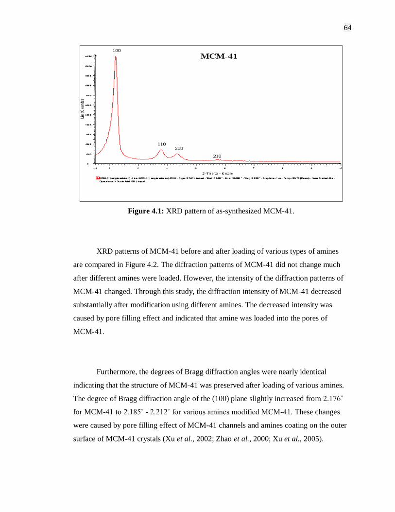
64
Figure 4.1: XRD pattern of as-synthesized MCM-41.
XRD patterns of MCM-41 before and after loading of various types of amines
are compared in Figure 4.2. The diffraction patterns of MCM-41 did not change much
after different amines were loaded. However, the intensity of the diffraction patterns of
MCM-41 changed. Through this study, the diffraction intensity of MCM-41 decreased
substantially after modification using different amines. The decreased intensity was
caused by pore filling effect and indicated that amine was loaded into the pores of
MCM-41.
Furthermore, the degrees of Bragg diffraction angles were nearly identical
indicating that the structure of MCM-41 was preserved after loading of various amines.
The degree of Bragg diffraction angle of the (100) plane slightly increased from 2.176˚
for MCM-41 to 2.185˚ - 2.212˚ for various amines modified MCM-41. These changes
were caused by pore filling effect of MCM-41 channels and amines coating on the outer
surface of MCM-41 crystals (Xu et al., 2002; Zhao et al., 2000; Xu et al., 2005).
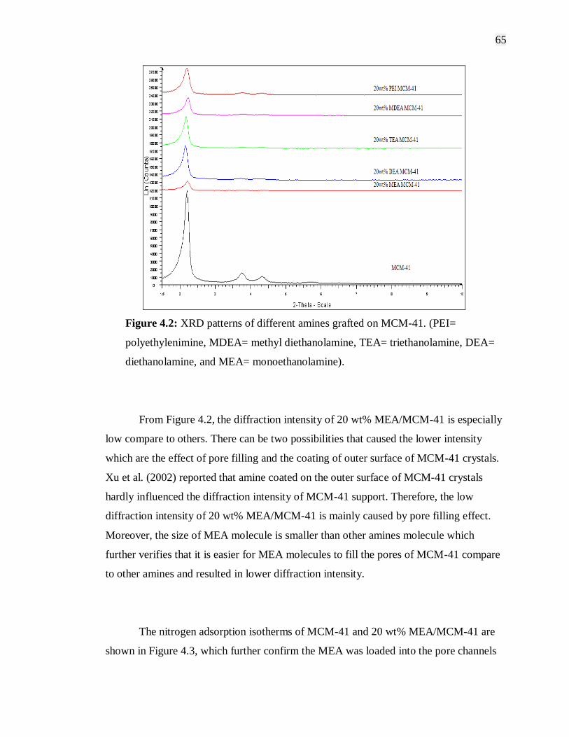
65
Figure 4.2: XRD patterns of different amines grafted on MCM-41. (PEI=
polyethylenimine, MDEA= methyl diethanolamine, TEA= triethanolamine, DEA=
diethanolamine, and MEA= monoethanolamine).
From Figure 4.2, the diffraction intensity of 20 wt% MEA/MCM-41 is especially
low compare to others. There can be two possibilities that caused the lower intensity
which are the effect of pore filling and the coating of outer surface of MCM-41 crystals.
Xu et al. (2002) reported that amine coated on the outer surface of MCM-41 crystals
hardly influenced the diffraction intensity of MCM-41 support. Therefore, the low
diffraction intensity of 20 wt% MEA/MCM-41 is mainly caused by pore filling effect.
Moreover, the size of MEA molecule is smaller than other amines molecule which
further verifies that it is easier for MEA molecules to fill the pores of MCM-41 compare
to other amines and resulted in lower diffraction intensity.
The nitrogen adsorption isotherms of MCM-41 and 20 wt% MEA/MCM-41 are
shown in Figure 4.3, which further confirm the MEA was loaded into the pore channels
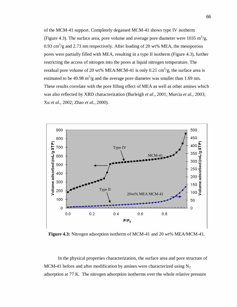
66
of the MCM-41 support. Completely degassed MCM-41 shows type IV isotherm
(Figure 4.3). The surface area, pore volume and average pore diameter were 1035 m2/g,
0.93 cm3/g and 2.73 nm respectively. After loading of 20 wt% MEA, the mesoporous
pores were partially filled with MEA, resulting in a type II isotherm (Figure 4.3), further
restricting the access of nitrogen into the pores at liquid nitrogen temperature. The
residual pore volume of 20 wt% MEA/MCM-41 is only 0.21 cm3/g, the surface area is
estimated to be 49.98 m2/g and the average pore diameter was smaller than 1.69 nm.
These results correlate with the pore filling effect of MEA as well as other amines which
was also reflected by XRD characterization (Burleigh et al., 2001; Murcia et al., 2003;
Xu et al., 2002; Zhao et al., 2000).
Figure 4.3: Nitrogen adsorption isotherm of MCM-41 and 20 wt% MEA/MCM-41.
In the physical properties characterization, the surface area and pore structure of
MCM-41 before and after modification by amines were characterized using N2
adsorption at 77 K. The nitrogen adsorption isotherms over the whole relative pressure
Type II
Type IV
20wt% MEA MCM-41
MCM-41
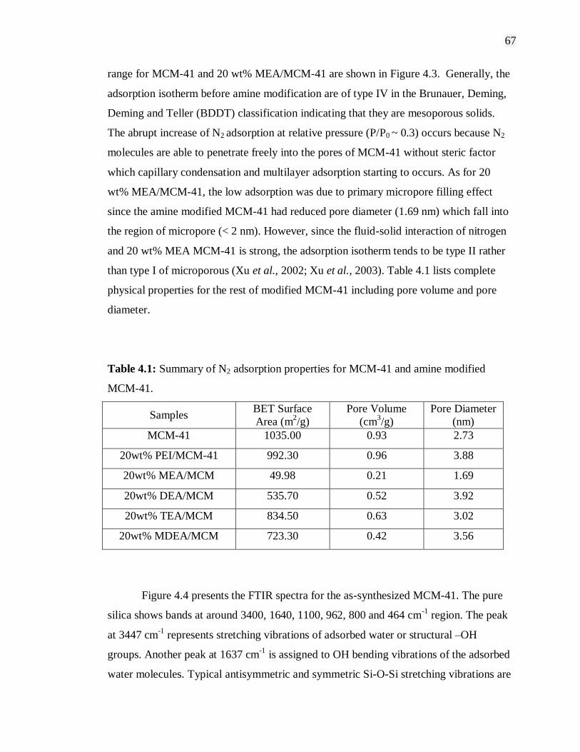
67
range for MCM-41 and 20 wt% MEA/MCM-41 are shown in Figure 4.3. Generally, the
adsorption isotherm before amine modification are of type IV in the Brunauer, Deming,
Deming and Teller (BDDT) classification indicating that they are mesoporous solids.
The abrupt increase of N2 adsorption at relative pressure (P/P0 ~ 0.3) occurs because N2
molecules are able to penetrate freely into the pores of MCM-41 without steric factor
which capillary condensation and multilayer adsorption starting to occurs. As for 20
wt% MEA/MCM-41, the low adsorption was due to primary micropore filling effect
since the amine modified MCM-41 had reduced pore diameter (1.69 nm) which fall into
the region of micropore (< 2 nm). However, since the fluid-solid interaction of nitrogen
and 20 wt% MEA MCM-41 is strong, the adsorption isotherm tends to be type II rather
than type I of microporous (Xu et al., 2002; Xu et al., 2003). Table 4.1 lists complete
physical properties for the rest of modified MCM-41 including pore volume and pore
diameter.
Table 4.1: Summary of N2 adsorption properties for MCM-41 and amine modified
MCM-41.
Samples BET Surface
Area (m2/g)
Pore Volume
(cm3/g)
Pore Diameter
(nm)
MCM-41 1035.00 0.93 2.73
20wt% PEI/MCM-41 992.30 0.96 3.88
20wt% MEA/MCM 49.98 0.21 1.69
20wt% DEA/MCM 535.70 0.52 3.92
20wt% TEA/MCM 834.50 0.63 3.02
20wt% MDEA/MCM 723.30 0.42 3.56
Figure 4.4 presents the FTIR spectra for the as-synthesized MCM-41. The pure
silica shows bands at around 3400, 1640, 1100, 962, 800 and 464 cm-1
region. The peak
at 3447 cm-1
represents stretching vibrations of adsorbed water or structural –OH
groups. Another peak at 1637 cm-1
is assigned to OH bending vibrations of the adsorbed
water molecules. Typical antisymmetric and symmetric Si-O-Si stretching vibrations are
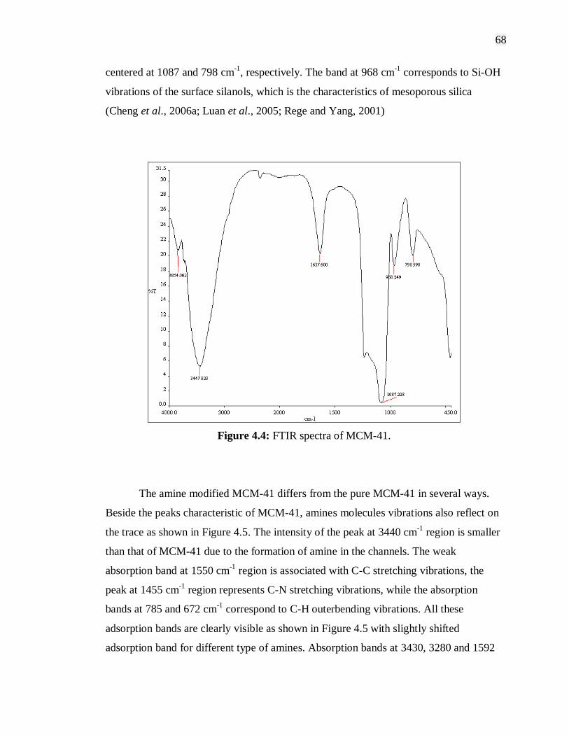
68
centered at 1087 and 798 cm-1
, respectively. The band at 968 cm-1
corresponds to Si-OH
vibrations of the surface silanols, which is the characteristics of mesoporous silica
(Cheng et al., 2006a; Luan et al., 2005; Rege and Yang, 2001)
Figure 4.4: FTIR spectra of MCM-41.
The amine modified MCM-41 differs from the pure MCM-41 in several ways.
Beside the peaks characteristic of MCM-41, amines molecules vibrations also reflect on
the trace as shown in Figure 4.5. The intensity of the peak at 3440 cm-1
region is smaller
than that of MCM-41 due to the formation of amine in the channels. The weak
absorption band at 1550 cm-1
region is associated with C-C stretching vibrations, the
peak at 1455 cm-1
region represents C-N stretching vibrations, while the absorption
bands at 785 and 672 cm-1
correspond to C-H outerbending vibrations. All these
adsorption bands are clearly visible as shown in Figure 4.5 with slightly shifted
adsorption band for different type of amines. Absorption bands at 3430, 3280 and 1592
69
cm-1
region are assigned to asymmetric NH2 stretch (νas NH2), symmetric NH2 stretch (νs
NH2) and NH2 deformation (δNH2) of hydrogen bonded amino group, respectively
(Cheng et al., 2006a; Zhao et al., 1996; Wakabayashi et al., 1997; Hiyoshi et al., 2005).
Besides these, absorption bands due to (Si-)OH stretch is visible at 3400 cm-1
region,
overtone of Si-O-Si lattice weak vibration at 1980 and 1850 cm-1
region, CH2 stretch at
2850 and 2930 cm-1
region and CH2 deformation at 1460 cm-1
region were also observed
in the spectrum which overlaps with C-N stretching vibrations. In addition, the peak at
1090 cm-1
region is assigned to the in-plane deformation vibrations of N+H2 formed on
the amine chains by protonation, which is overlapped by the peak of the antisymmetric
Si-O-Si stretching vibrations of MCM-41 (Zheng et al., 2005; Cheng et al., 2006a;
Hiyoshi et al., 2005). As for secondary amine (DEA), the absorption peak of NH stretch
(ν NH) would overlap with symmetric NH2 stretch (νs NH2) at around 3300 cm-1
.
Meanwhile, as for tertiary amine (TEA) the peak at 1456 cm-1
will be the dominant
absorption band represents C-N stretching vibrations as can be seen in Figure 4.5 for the
spectrum of 20 wt% TEA/MCM-41.

70
Figure 4.5: FTIR spectra of amines modified MCM-41.
Thus, the FTIR spectra of amine modified MCM-41 confirm the incorporation of
amine inside the pore channels of MCM-41. Small shifts between the absorption peaks
of amine molecules in the nanocomposite and bulk amine suggest that chain growth of
amine in the mesopores is limited by diffusional restriction (Cheng et al., 2006a; Cheng
et al., 2006b; Luan and Fournier, 2005).

71
4.2.2 Effects of Metals Loading
XRD patterns of different metals loading on MCM-41 are shown in Figure 4.6.
There is no obvious decrease in peak intensity observed which indicates that ordered
hexagonal mesoporous structure is well developed for each metal modified MCM-41.
Furthermore, the presence of 3 smaller peaks (d110, d200 and d210 peaks) confirms that
long range order was present in the samples.
Figure 4.6: XRD patterns of MCM-41 and 0.5wt% 0f different metals loading on
MCM-41. (Cu= copper, Ni= nickel, Co= cobalt).
The calcination process in the direct synthesis of metal modified MCM-41
method used high temperature at 550˚C. This may results in oxidation of metal nitrate
which is used in the synthesis to form bulk metal oxide (CuNO3 → CuO, NiNO3 → NiO
and CoNO3 → Co3O4). Moreover, the high calcination temperature may also transport
some of metal oxide species out of the pore system and remove some of their deposition
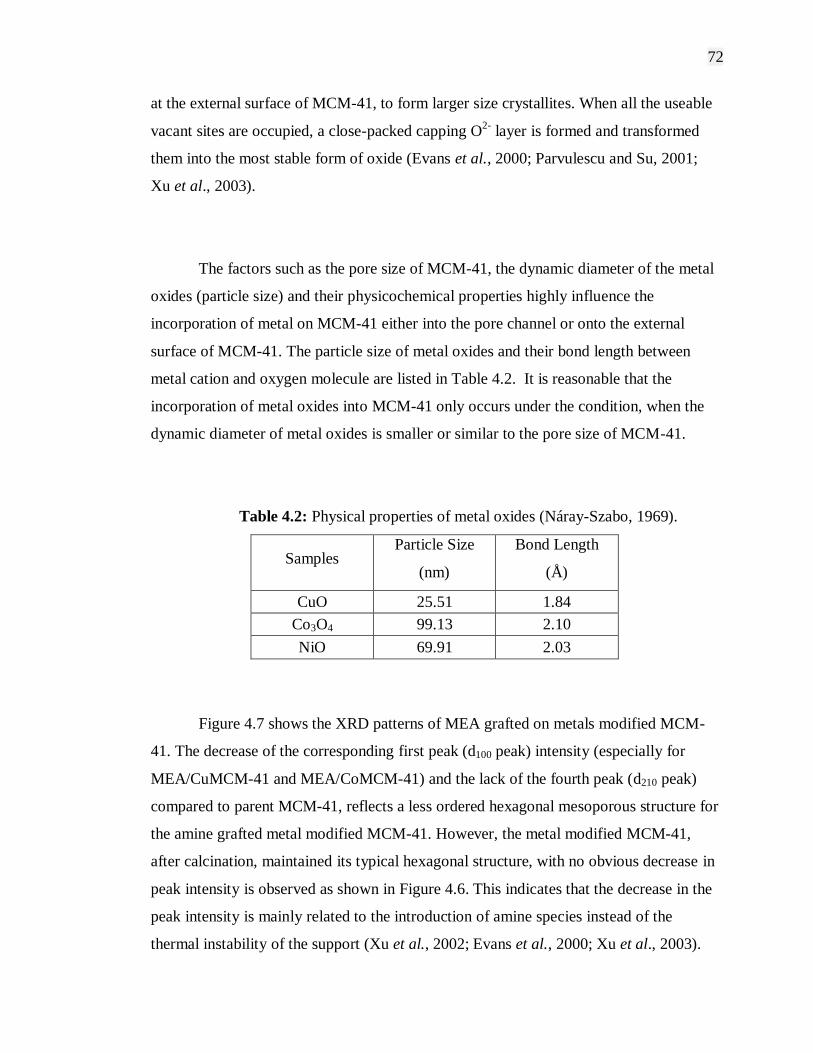
72
at the external surface of MCM-41, to form larger size crystallites. When all the useable
vacant sites are occupied, a close-packed capping O2-
layer is formed and transformed
them into the most stable form of oxide (Evans et al., 2000; Parvulescu and Su, 2001;
Xu et al., 2003).
The factors such as the pore size of MCM-41, the dynamic diameter of the metal
oxides (particle size) and their physicochemical properties highly influence the
incorporation of metal on MCM-41 either into the pore channel or onto the external
surface of MCM-41. The particle size of metal oxides and their bond length between
metal cation and oxygen molecule are listed in Table 4.2. It is reasonable that the
incorporation of metal oxides into MCM-41 only occurs under the condition, when the
dynamic diameter of metal oxides is smaller or similar to the pore size of MCM-41.
Table 4.2: Physical properties of metal oxides (Náray-Szabo, 1969).
Samples Particle Size
(nm)
Bond Length
(Å)
CuO 25.51 1.84
Co3O4 99.13 2.10
NiO 69.91 2.03
Figure 4.7 shows the XRD patterns of MEA grafted on metals modified MCM-
41. The decrease of the corresponding first peak (d100 peak) intensity (especially for
MEA/CuMCM-41 and MEA/CoMCM-41) and the lack of the fourth peak (d210 peak)
compared to parent MCM-41, reflects a less ordered hexagonal mesoporous structure for
the amine grafted metal modified MCM-41. However, the metal modified MCM-41,
after calcination, maintained its typical hexagonal structure, with no obvious decrease in
peak intensity is observed as shown in Figure 4.6. This indicates that the decrease in the
peak intensity is mainly related to the introduction of amine species instead of the
thermal instability of the support (Xu et al., 2002; Evans et al., 2000; Xu et al., 2003).

73
Thus, it is confirm that the decreased intensity was caused by the amine coating on the
outer surface of metal modified MCM-41 crystals as well as pore filling effect which
further indicates that amine was loaded into the pores of modified MCM-41.
Figure 4.7: XRD patterns of 20wt% MEA grafted on different metals modified MCM-
41.
4.2.3 Effects of Amine on Microporous Materials
Powder X-Ray Diffraction has also been used to characterize the crystallinity
and structure of microporous materials used in this study which are NaY and 13X. The
flat baselines of the X-ray diffraction pattern as shown in Figures 4.8 and 4.9 indicated a
good crystallinity of all the samples. It was observed that the peak intensities of the
XRD reflections for MEA modified NaY and 13X decreased as compared to unmodified
commercial NaY and 13X. This is due to the presence of MEA particles within the

74
framework of the zeolite NaY and 13X. This result shows similarity as to MEA
modified MCM-41. Therefore, regardless of the size of pores, the peak intensities of the
XRD patterns decreased after incorporation of amines.
Figure 4.8: XRD patterns of zeolite NaY and MEA modified NaY.
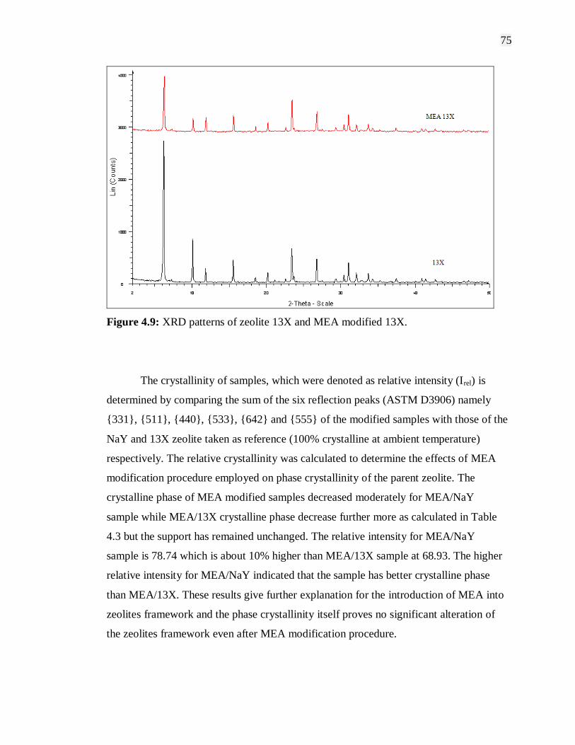
75
Figure 4.9: XRD patterns of zeolite 13X and MEA modified 13X.
The crystallinity of samples, which were denoted as relative intensity (Irel) is
determined by comparing the sum of the six reflection peaks (ASTM D3906) namely
{331}, {511}, {440}, {533}, {642} and {555} of the modified samples with those of the
NaY and 13X zeolite taken as reference (100% crystalline at ambient temperature)
respectively. The relative crystallinity was calculated to determine the effects of MEA
modification procedure employed on phase crystallinity of the parent zeolite. The
crystalline phase of MEA modified samples decreased moderately for MEA/NaY
sample while MEA/13X crystalline phase decrease further more as calculated in Table
4.3 but the support has remained unchanged. The relative intensity for MEA/NaY
sample is 78.74 which is about 10% higher than MEA/13X sample at 68.93. The higher
relative intensity for MEA/NaY indicated that the sample has better crystalline phase
than MEA/13X. These results give further explanation for the introduction of MEA into
zeolites framework and the phase crystallinity itself proves no significant alteration of
the zeolites framework even after MEA modification procedure.
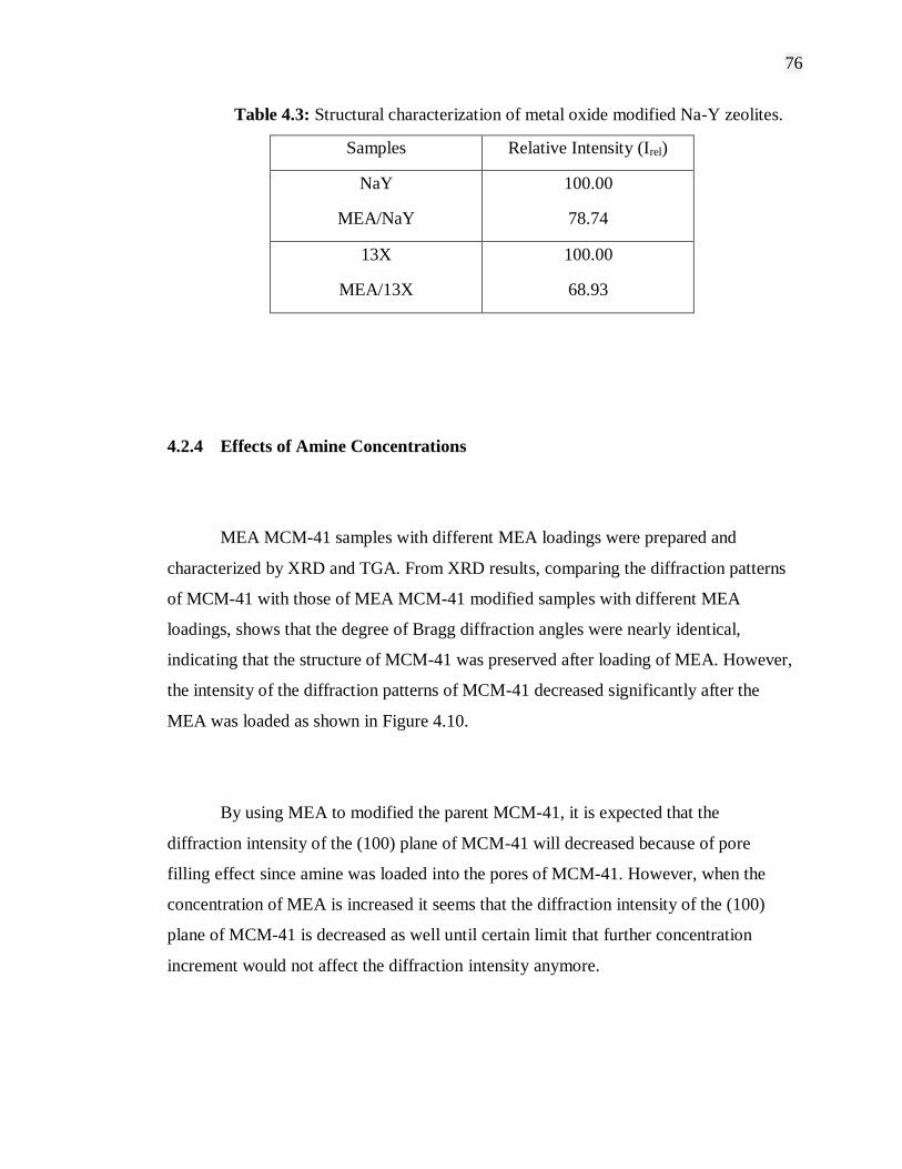
76
Table 4.3: Structural characterization of metal oxide modified Na-Y zeolites.
Samples Relative Intensity (Irel)
NaY 100.00
MEA/NaY 78.74
13X 100.00
MEA/13X 68.93
4.2.4 Effects of Amine Concentrations
MEA MCM-41 samples with different MEA loadings were prepared and
characterized by XRD and TGA. From XRD results, comparing the diffraction patterns
of MCM-41 with those of MEA MCM-41 modified samples with different MEA
loadings, shows that the degree of Bragg diffraction angles were nearly identical,
indicating that the structure of MCM-41 was preserved after loading of MEA. However,
the intensity of the diffraction patterns of MCM-41 decreased significantly after the
MEA was loaded as shown in Figure 4.10.
By using MEA to modified the parent MCM-41, it is expected that the
diffraction intensity of the (100) plane of MCM-41 will decreased because of pore
filling effect since amine was loaded into the pores of MCM-41. However, when the
concentration of MEA is increased it seems that the diffraction intensity of the (100)
plane of MCM-41 is decreased as well until certain limit that further concentration
increment would not affect the diffraction intensity anymore.
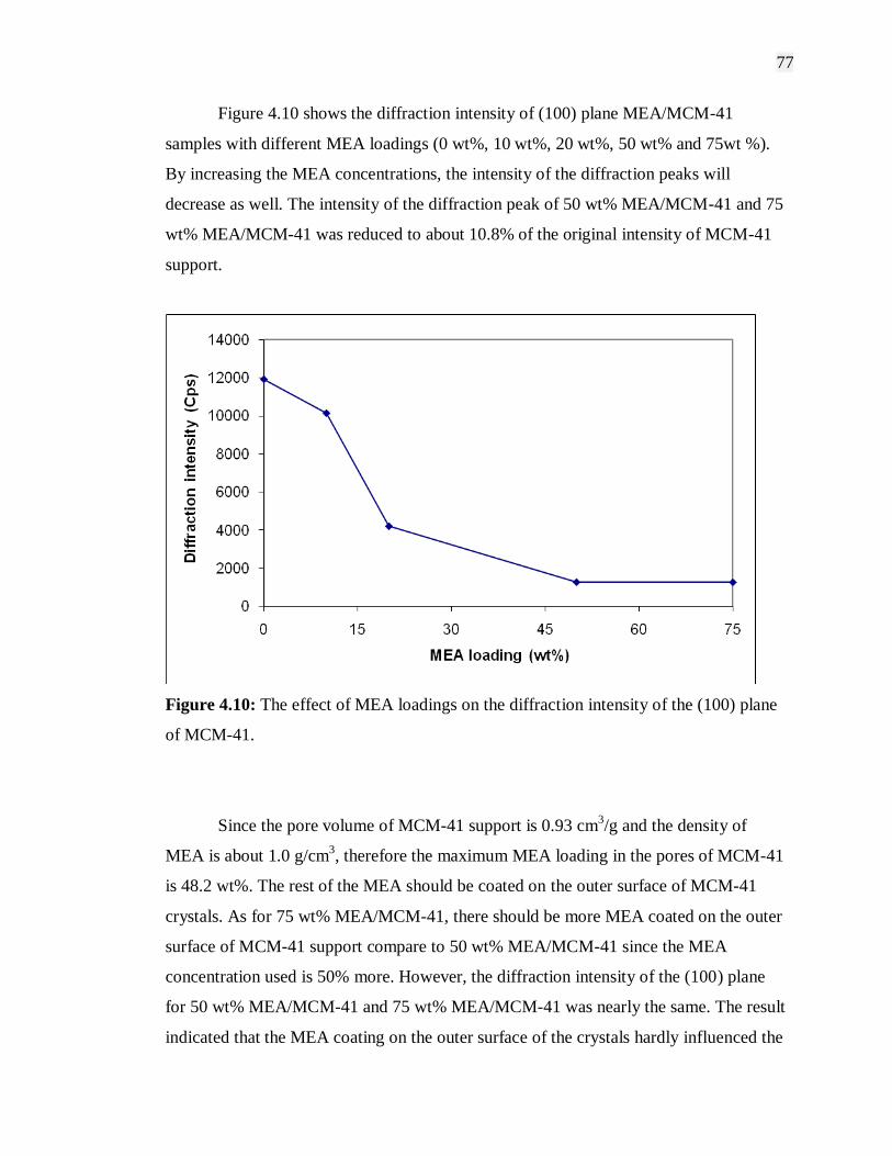
77
Figure 4.10 shows the diffraction intensity of (100) plane MEA/MCM-41
samples with different MEA loadings (0 wt%, 10 wt%, 20 wt%, 50 wt% and 75wt %).
By increasing the MEA concentrations, the intensity of the diffraction peaks will
decrease as well. The intensity of the diffraction peak of 50 wt% MEA/MCM-41 and 75
wt% MEA/MCM-41 was reduced to about 10.8% of the original intensity of MCM-41
support.
Figure 4.10: The effect of MEA loadings on the diffraction intensity of the (100) plane
of MCM-41.
Since the pore volume of MCM-41 support is 0.93 cm3/g and the density of
MEA is about 1.0 g/cm3, therefore the maximum MEA loading in the pores of MCM-41
is 48.2 wt%. The rest of the MEA should be coated on the outer surface of MCM-41
crystals. As for 75 wt% MEA/MCM-41, there should be more MEA coated on the outer
surface of MCM-41 support compare to 50 wt% MEA/MCM-41 since the MEA
concentration used is 50% more. However, the diffraction intensity of the (100) plane
for 50 wt% MEA/MCM-41 and 75 wt% MEA/MCM-41 was nearly the same. The result
indicated that the MEA coating on the outer surface of the crystals hardly influenced the

78
diffraction intensity of the MCM-41 support. Therefore, the decrease in the diffraction
intensity of the (100) plane can be ascribed mainly to the loading of MEA into the
MCM-41‟s pore channels (Xu et al., 2002; Xu et al., 2003).
4.3 Carbon Dioxide Adsorption Characteristics
Gas CO2 adsorption capacity of amine modified mesoporous and microporous
materials were studied and presented in the following section. Based upon the results
obtained from the equilibrium adsorption capacity, the effects of amine modification on
the CO2 adsorption could be evaluated and characterized. The procedures for evaluation
of gas CO2 adsorption capacity by amine modified mesoporous and microporous
materials were investigated in single adsorbate adsorption atmosphere at equilibrium
pressure of 138 kPa and 50˚C as a standard operating temperature. All amines use for
modification is standardized at 20 wt%. Adsorbate uptake capacity was measured until
equilibrium reached.
4.3.1 Effects of Various Amines
Before amine was loaded, MCM-41 support alone shows CO2 adsorption
capacity of 18.58 mg/g sorbent. The low adsorption capacity was due to weak
interaction between CO2 and MCM-41 at relatively high temperature. In order to
strengthen the interaction between CO2 and MCM-41, different types of amines with
numerous CO2-capturing sites were incorporated into/onto MCM-41.
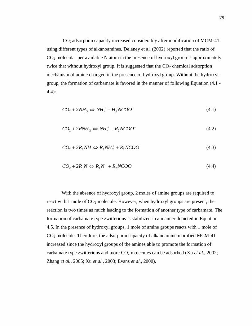
79
CO2 adsorption capacity increased considerably after modification of MCM-41
using different types of alkanoamines. Delaney et al. (2002) reported that the ratio of
CO2 molecular per available N atom in the presence of hydroxyl group is approximately
twice that without hydroxyl group. It is suggested that the CO2 chemical adsorption
mechanism of amine changed in the presence of hydroxyl group. Without the hydroxyl
group, the formation of carbamate is favored in the manner of following Equation (4.1 -
4.4):
NCOOHNHNHCO 2432 2 (4.1)
NCOORNHRNHCO 2422 2 (4.2)
NCOORNHRNHRCO 22222 2 (4.3)
NCOORNRNRCO 2432 2 (4.4)
With the absence of hydroxyl group, 2 moles of amine groups are required to
react with 1 mole of CO2 molecule. However, when hydroxyl groups are present, the
reaction is two times as much leading to the formation of another type of carbamate. The
formation of carbamate type zwitterions is stabilized in a manner depicted in Equation
4.5. In the presence of hydroxyl groups, 1 mole of amine groups reacts with 1 mole of
CO2 molecule. Therefore, the adsorption capacity of alkanoamine modified MCM-41
increased since the hydroxyl groups of the amines able to promote the formation of
carbamate type zwitterions and more CO2 molecules can be adsorbed (Xu et al., 2002;
Zhang et al., 2005; Xu et al., 2003; Evans et al., 2000).

80
N 2CO N (4.5)
HO O HO
HO O HO
To further understand the reaction theory, let‟s discuss on the interaction
between the basic surface of adsorbents and acidic CO2 molecules. There are two
conditions which affect the interaction between the amine modified silanol surface and
CO2 molecules. First, under anhydrous conditions, the reaction tends toward the
formation of surface ammonium carbamates. Second, the reaction tends toward the
formation of ammonium bicarbonate and carbonate species in the presence of water
(Xiao et al., 2002; Knowles et al., 2005). Thus, in dry CO2 which is in my case,
adsorption capacities are limited to 1 mol of CO2 for every 2 mol surface-bound amine
groups. However, adsorption capacities may increase up to 2 mol of CO2 with every 2
mol of surface-bound amine groups when water is presence. Therefore, it is desirable to
develop adsorbents with the highest possible concentration of basic nitrogen groups
accessible to CO2 (Knowles et al., 2005; Xu et al., 2003; Guli et al., 2007). Figure 4.11
further demonstrate the reaction between amine groups on the silanol surface and CO2.
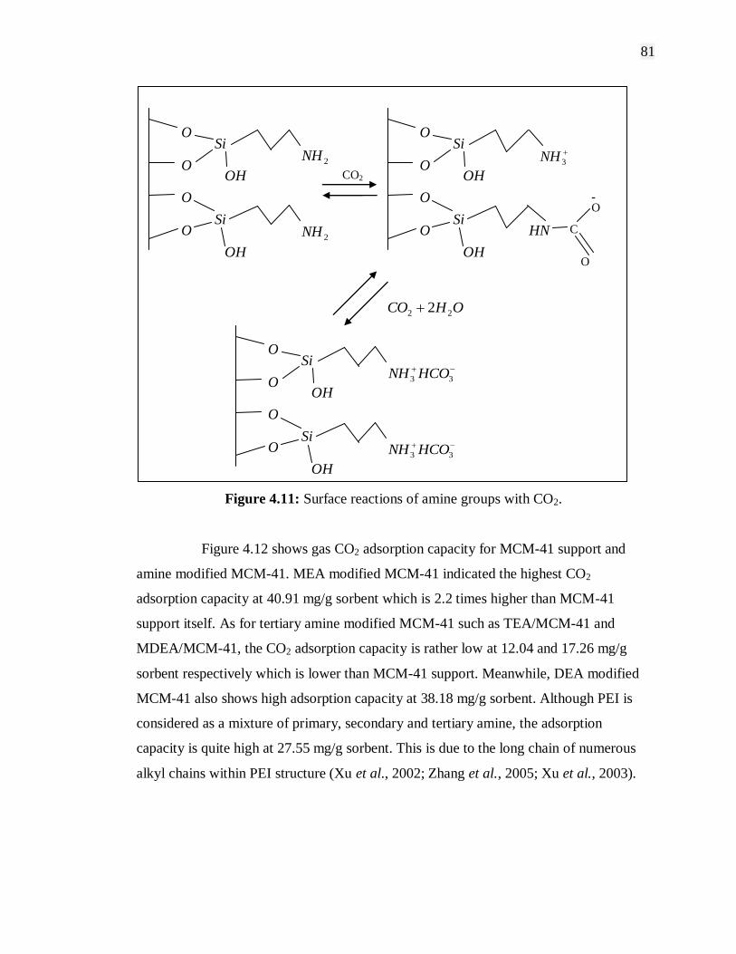
81
Figure 4.11: Surface reactions of amine groups with CO2.
Figure 4.12 shows gas CO2 adsorption capacity for MCM-41 support and
amine modified MCM-41. MEA modified MCM-41 indicated the highest CO2
adsorption capacity at 40.91 mg/g sorbent which is 2.2 times higher than MCM-41
support itself. As for tertiary amine modified MCM-41 such as TEA/MCM-41 and
MDEA/MCM-41, the CO2 adsorption capacity is rather low at 12.04 and 17.26 mg/g
sorbent respectively which is lower than MCM-41 support. Meanwhile, DEA modified
MCM-41 also shows high adsorption capacity at 38.18 mg/g sorbent. Although PEI is
considered as a mixture of primary, secondary and tertiary amine, the adsorption
capacity is quite high at 27.55 mg/g sorbent. This is due to the long chain of numerous
alkyl chains within PEI structure (Xu et al., 2002; Zhang et al., 2005; Xu et al., 2003).
2NH
CO2
3NH
HN C
O
O -
OHCO 22 2
33 HCONH
O Si
OH
33 HCONH
OH
2NH
Si
O
O
O
O Si
OH
OH
Si
O
O
O
O Si
OH
OH
Si
O
O
O

82
Figure 4.12: Gas CO2 adsorption capacity for MCM-41 support and amines modified
MCM-41.
There are two possible reasons for synergetic effect of MCM-41, one is the high
surface area of MCM-41 and another is the uniform mesoporous channel of MCM-41.
When amine was loaded onto the materials with high surface area, there will be more
CO2 affinity sites exposed to the adsorbate and thus increasing the adsorption capacity.
When the channels of MCM-41 are filled by amine, the apparent pore size of the parent
MCM-41 will be decreased as discussed. Hence, reducing the pore volume and
decreasing the maximum CO2 adsorption capacity. However, at the same time more CO2
affinity sites are introduced into the pore channel of MCM-41. Both these contradicting
effects occurred simultaneously and directly affected the adsorption capacity.
The amount of CO2 adsorbed increases with increasing of the straight alkyl chain
in the amines. PEI is one example of this case which consists of numerous long alkyl
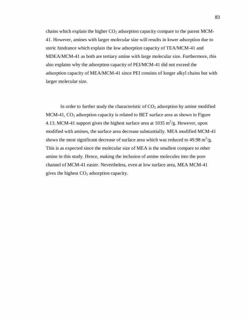
83
chains which explain the higher CO2 adsorption capacity compare to the parent MCM-
41. However, amines with larger molecular size will results in lower adsorption due to
steric hindrance which explain the low adsorption capacity of TEA/MCM-41 and
MDEA/MCM-41 as both are tertiary amine with large molecular size. Furthermore, this
also explains why the adsorption capacity of PEI/MCM-41 did not exceed the
adsorption capacity of MEA/MCM-41 since PEI consists of longer alkyl chains but with
larger molecular size.
In order to further study the characteristic of CO2 adsorption by amine modified
MCM-41, CO2 adsorption capacity is related to BET surface area as shown in Figure
4.13. MCM-41 support gives the highest surface area at 1035 m2/g. However, upon
modified with amines, the surface area decrease substantially. MEA modified MCM-41
shows the most significant decrease of surface area which was reduced to 49.98 m2/g.
This is as expected since the molecular size of MEA is the smallest compare to other
amine in this study. Hence, making the inclusion of amine molecules into the pore
channel of MCM-41 easier. Nevertheless, even at low surface area, MEA MCM-41
gives the highest CO2 adsorption capacity.
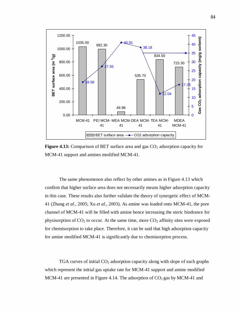
84
1035.00992.30
49.98
535.70
834.50
723.30
18.58
40.91
38.18
12.04
17.26
27.55
0.00
200.00
400.00
600.00
800.00
1000.00
1200.00
MCM-41 PEI MCM-
41
MEA MCM-
41
DEA MCM-
41
TEA MCM-
41
MDEA
MCM-41
BE
T s
urf
ace a
rea (
m2/g
)
0
5
10
15
20
25
30
35
40
45
Gas C
O2 a
dso
rpti
on
cap
asit
y (
mg
/g s
orb
en
t)
BET surface area CO2 adsorption capacity
Figure 4.13: Comparison of BET surface area and gas CO2 adsorption capacity for
MCM-41 support and amines modified MCM-41.
The same phenomenon also reflect by other amines as in Figure 4.13 which
confirm that higher surface area does not necessarily means higher adsorption capacity
in this case. These results also further validate the theory of synergetic effect of MCM-
41 (Zhang et al., 2005; Xu et al., 2003). As amine was loaded onto MCM-41, the pore
channel of MCM-41 will be filled with amine hence increasing the steric hindrance for
physisorption of CO2 to occur. At the same time, more CO2 affinity sites were exposed
for chemisorption to take place. Therefore, it can be said that high adsorption capacity
for amine modified MCM-41 is significantly due to chemisorption process.
TGA curves of initial CO2 adsorption capacity along with slope of each graphs
which represent the initial gas uptake rate for MCM-41 support and amine modified
MCM-41 are presented in Figure 4.14. The adsorption of CO2 gas by MCM-41 and
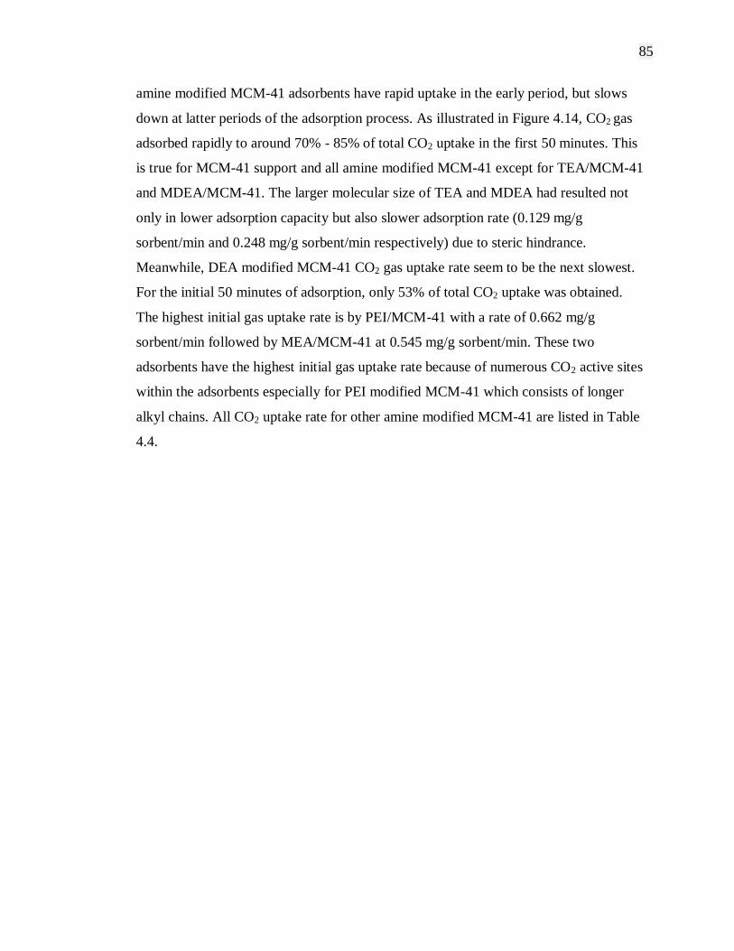
85
amine modified MCM-41 adsorbents have rapid uptake in the early period, but slows
down at latter periods of the adsorption process. As illustrated in Figure 4.14, CO2 gas
adsorbed rapidly to around 70% - 85% of total CO2 uptake in the first 50 minutes. This
is true for MCM-41 support and all amine modified MCM-41 except for TEA/MCM-41
and MDEA/MCM-41. The larger molecular size of TEA and MDEA had resulted not
only in lower adsorption capacity but also slower adsorption rate (0.129 mg/g
sorbent/min and 0.248 mg/g sorbent/min respectively) due to steric hindrance.
Meanwhile, DEA modified MCM-41 CO2 gas uptake rate seem to be the next slowest.
For the initial 50 minutes of adsorption, only 53% of total CO2 uptake was obtained.
The highest initial gas uptake rate is by PEI/MCM-41 with a rate of 0.662 mg/g
sorbent/min followed by MEA/MCM-41 at 0.545 mg/g sorbent/min. These two
adsorbents have the highest initial gas uptake rate because of numerous CO2 active sites
within the adsorbents especially for PEI modified MCM-41 which consists of longer
alkyl chains. All CO2 uptake rate for other amine modified MCM-41 are listed in Table
4.4.
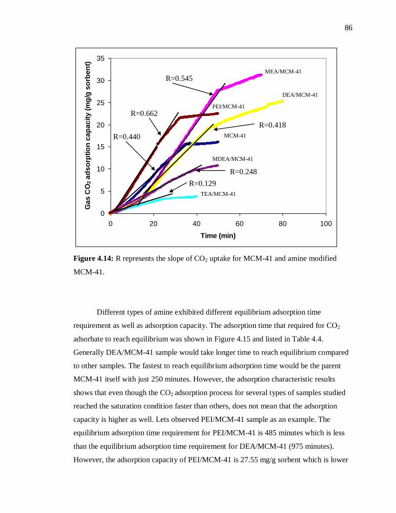
86
0
5
10
15
20
25
30
35
0 20 40 60 80 100
Time (min)
Ga
s C
O2 a
ds
orp
tio
n c
ap
ac
ity
(m
g/g
so
rbe
nt)
Figure 4.14: R represents the slope of CO2 uptake for MCM-41 and amine modified
MCM-41.
Different types of amine exhibited different equilibrium adsorption time
requirement as well as adsorption capacity. The adsorption time that required for CO2
adsorbate to reach equilibrium was shown in Figure 4.15 and listed in Table 4.4.
Generally DEA/MCM-41 sample would take longer time to reach equilibrium compared
to other samples. The fastest to reach equilibrium adsorption time would be the parent
MCM-41 itself with just 250 minutes. However, the adsorption characteristic results
shows that even though the CO2 adsorption process for several types of samples studied
reached the saturation condition faster than others, does not mean that the adsorption
capacity is higher as well. Lets observed PEI/MCM-41 sample as an example. The
equilibrium adsorption time requirement for PEI/MCM-41 is 485 minutes which is less
than the equilibrium adsorption time requirement for DEA/MCM-41 (975 minutes).
However, the adsorption capacity of PEI/MCM-41 is 27.55 mg/g sorbent which is lower
R=0.129
R=0.248
R=0.662
R=0.418
R=0.545
R=0.440
TEA/MCM-41
MDEA/MCM-41
MCM-41
PEI/MCM-41
DEA/MCM-41
MEA/MCM-41
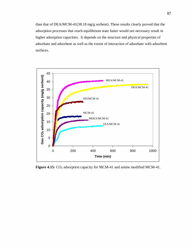
87
than that of DEA/MCM-41(38.18 mg/g sorbent). These results clearly proved that the
adsorption processes that reach equilibrium state faster would not necessary result in
higher adsorption capacities. It depends on the structure and physical properties of
adsorbate and adsorbent as well as the extent of interaction of adsorbate with adsorbent
surfaces.
0
5
10
15
20
25
30
35
40
45
0 200 400 600 800 1000
Time (min)
Ga
s C
O2 a
ds
orp
tio
n c
ap
ac
ity
(m
g/g
so
rbe
nt)
Figure 4.15: CO2 adsorption capacity for MCM-41 and amine modified MCM-41.
DEA/MCM-41
PEI/MCM-41
MCM-41
MDEA/MCM-41
TEA/MCM-41
MEA/MCM-41
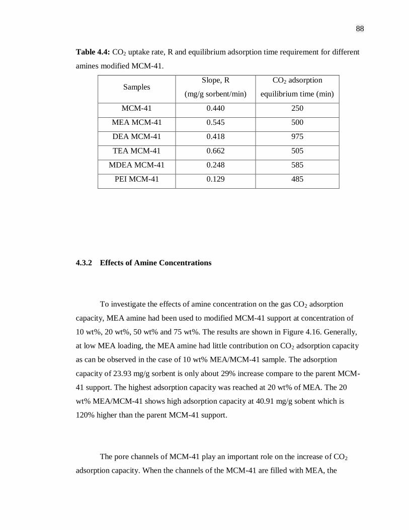
88
Table 4.4: CO2 uptake rate, R and equilibrium adsorption time requirement for different
amines modified MCM-41.
Samples Slope, R
(mg/g sorbent/min)
CO2 adsorption
equilibrium time (min)
MCM-41 0.440 250
MEA MCM-41 0.545 500
DEA MCM-41 0.418 975
TEA MCM-41 0.662 505
MDEA MCM-41 0.248 585
PEI MCM-41 0.129 485
4.3.2 Effects of Amine Concentrations
To investigate the effects of amine concentration on the gas CO2 adsorption
capacity, MEA amine had been used to modified MCM-41 support at concentration of
10 wt%, 20 wt%, 50 wt% and 75 wt%. The results are shown in Figure 4.16. Generally,
at low MEA loading, the MEA amine had little contribution on CO2 adsorption capacity
as can be observed in the case of 10 wt% MEA/MCM-41 sample. The adsorption
capacity of 23.93 mg/g sorbent is only about 29% increase compare to the parent MCM-
41 support. The highest adsorption capacity was reached at 20 wt% of MEA. The 20
wt% MEA/MCM-41 shows high adsorption capacity at 40.91 mg/g sobent which is
120% higher than the parent MCM-41 support.
The pore channels of MCM-41 play an important role on the increase of CO2
adsorption capacity. When the channels of the MCM-41 are filled with MEA, the

89
apparent pore size of the MCM-41 will be decreased. At the same time, more CO2
affinity sites are introduced into the channel. These two effects may combine together
and result in further increment of the adsorption capacity. In the case of MEA modified
MCM-41, physisorption and chemisorption take place at the same time. Physisorption
on the MEA/MCM-41 sample occur mainly in the pore channels of MCM-41 support,
while chemisorption involve the reaction of CO2 and MEA in the channels of MCM-41
as well as on the external surface of MCM-41. When the channels of MCM-41 are fully
filled with MEA, the highest adsorption capacity can be obtained. When MEA
concentration was further increased and the MEA begin to coat on the external surface
of MCM-41, the adsorption capacity starting to decrease (Xu et al., 2002; Xu et al.,
2003). Therefore, as can be observed from Figure 4.16, higher MEA concentration at 50
wt% and 75 wt% resulted in reduced adsorption capacity as more pore channel of
MCM-41 being filled with MEA hence blocking the pore channels for physisorption to
occur resulting in steric hindrance (McKittrick and Jones, 2003).
18.58
23.93
40.91
22.47
19.36
0
5
10
15
20
25
30
35
40
45
MCM-41 10 wt% MEA
MCM-41
20 wt% MEA
MCM-41
50 wt% MEA
MCM-41
75 wt% MEA
MCM-41
Gas C
O2 a
dso
rpti
on
cap
asit
y (
mg
/g s
orb
en
t)
Figure 4.16: Gas CO2 adsorption capacity for MEA modified MCM-41 at different
concentrations.

90
Figure 4.17 presents the TGA curves of CO2 adsorption capacity for MEA
modified MCM-41 at MEA concentration of 10 wt%, 20 wt%, 50 wt% and 75 wt%.
There is no specific trend in CO2 equilibrium adsorption time requirement when
increasing the MEA concentration. The fastest CO2 equilibrium time reached is
achieved by 50 wt% MEA/MCM-41 sample which took only 200 minutes to reach
equilibrium. 50 wt% MEA/MCM-41 not only require less time to reach equilibrium but
also has a high rate of CO2 uptake which reached 90% of total CO2 uptake in just 50
minutes at a rate of 0.535 mg/g sorbent/min. Sample 20 wt% MEA/MCM-41 still the
slowest to reach equilibrium at 500 minutes but has the highest CO2 uptake rate at 0.545
mg/g sorbent/min and was able to reach the highest adsorption capacity compare to
other concentration. The results show that at 20 wt% of MEA concentration,
physisorption and chemisorption were able to occur synergeticly. The MEA amine
occupied the pore channels of MCM-41 but still leave some space adequate enough for
CO2 molecules to adsorb (physisorption) added by chemisorption on the external and
internal surface of MCM-41 produced the highest adsorption capacity. The amine
concentration higher than 50 wt% would cause blockage of the pore channels hence
making the CO2 penetration into the channels harder and consequently lower adsorption
capacity. All CO2 uptake rate and CO2 adsorption equilibrium time for MEA modified
MCM-41 at different concentrations are listed in Table 4.5.

91
0
5
10
15
20
25
30
35
40
45
0 100 200 300 400 500 600
Time (min)
Ga
s C
O2 a
ds
orp
tio
n c
ap
ac
ity
(m
g/g
so
rbe
nt)
Figure 4.17: CO2 adsorption capacity for MEA modified MCM-41 at different
concentrations.
Table 4.5: CO2 uptake rate and equilibrium adsorption time requirement for MEA
modified MCM-41 at different concentrations.
Samples CO2 uptake rate
(mg/g sorbent/min)
CO2 adsorption
equilibrium time (min)
MCM-41 0.440 250
10 wt% MEA/MCM-41 0.486 300
20 wt% MEA/MCM 0.545 500
50 wt% MEA/MCM 0.535 200
75 wt% MEA/MCM 0.384 350
MCM-41
10 wt% MEA/MCM-41
20 wt% MEA/MCM-41
50 wt% MEA/MCM-41 75 wt% MEA/MCM-41
92
4.3.3 Effects of Support Materials
In order to investigate the effects of different support materials on CO2
adsorption characteristics, mesoporous and microporous supports were utilized in the
study as well as amine and metal nitrates as the modify agents. Mesoporous supports
synthesized in the study are MCM-41 and SBA-15, meanwhile microporous supports of
NaY and 13X are obtained commercially. Three Metal nitrates was chosen namely
copper nitrate, cobalt nitrate and nickel nitrate to incorporate into MCM-41 support
during direct synthesis. Then, MEA was used as the standard modify agent for each of
the supports. The CO2 adsorption characterization of the adsorbents produced was done
by thermal gravimetric analyzer at standard condition of 138 kPa CO2 gas pressure and
50˚C of adsorption temperature.
At low loadings, materials with the strongest enthalpic interactions with sorbed
molecules showed the highest level of adsorption. These tend to be materials with
narrow pores, because small pores increase the interaction between gas and the
framework. However, materials with narrow pores also have the highest framework
densities and thus the lowest amount of free void space per gram of material. Therefore,
at the highest pressure when the pores are nearly filled, the materials with the largest
free volumes have more room for quest molecules and consequently show the highest
uptake (Frost et al., 2006).
Three different adsorption regimes can be identified. At low pressure, the
amount adsorbed correlates with the heat of adsorption. At intermediate pressure, the
amount adsorbed correlates with the surface area. And at the highest pressure, the
amount adsorbed correlates with the free volume. According to Frost et al., hydrogen
molecules adsorbed less for zeolite Y than for zeolite X. As zeolite Y has fewer
exchangeable cations (and consequently more void space) than zeolite X, these results
93
indicate that interaction of hydrogen molecules with exchangeable cations is important
to adsorption process. For zeolite X and Y, hydrogen uptake relates closely to the BET
surface area.
Figure 4.18 shows gas CO2 adsorption capacity for various mesoporous and
microporous supports as well as the 20 wt% MEA modified of each supports. From the
figure, the adsorption capacity of microporous supports (NaY and 13X) shows
significantly high level of CO2 adsorption compare to mesoporous supports. The highest
adsorption is achieved by NaY support at 183.57 mg/g sorbent which is about 9.9 times
higher than MCM-41 support. This is due to the high level of interaction between CO2
gas and the framework of NaY with such narrow pores at low pressure condition. This
also applied to 13X support which shows slightly decreased adsorption capacity at
162.02 mg/g sorbent. However, after the modification using MEA was grafted onto
these supports, the adsorption capacity significantly decreased by up to 60% of its
original adsorption capacity. This phenomenon is due to pore blockage by the amine
molecules since the pore size of microporous supports (cages ~ 0.74 nm, supercages ~
1.3 nm) is smaller than the approximately larger radius of the amine (~1.4 nm)
(Weitkamp, 2000; Inoue et al., 1991). When using MEA to modify microporous
supports, the amine tends to disperse on the surface of the zeolite framework hence
covering the pore of the support. Although MEA itself does provide additional CO2
adsorption site, but adsorption in the pore of the zeolite framework seems to be the more
significant role affecting the adsorption capacity. Furthermore, the crystalline phase of
NaY and 13X decreased after modification by MEA as calculated in Table 4.3. The
relative intensity for MEA/NaY sample is 78.74 which is higher than MEA/13X sample
at 68.93. The higher relative intensity for MEA/NaY indicated that the sample has better
crystalline phase than MEA/13X which explained the higher CO2 adsorption capacity
for MEA modified NaY. Besides, the decreased crystalline phase for both NaY and 13X
after MEA modification clarify the decreased adsorption capacity of the MEA modified
microporuos supports.

94
Figure 4.18: Gas CO2 adsorption capacity for various mesoporous and microporous
supports and MEA modified supports.
Meanwhile, as for mesoporous supports, all MEA grafted mesoporous supports
show increment in CO2 adsorption capacity except for MEA modified Co/MCM-41
sample. Based on Table 4.2, cobalt oxide has the largest particle size compare to the
other two metal oxides. Co3O4 particle size is 1.4 times larger than NiO particle size and
3.9 times larger than CuO particle size. The large particle size of Co3O4 formed on the
surface of the support after calcination proved to be the cause of low adsorption capacity
by blocking the pores of the support. As for Cu/MCM-41 and Ni/MCM-41 supports,
after grafting of MEA show only a small increase in adsorption capacity. The results
show that MEA is not the appropriate modify agent to improve adsorption capacity for
metal modified supports.
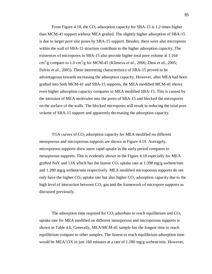
95
From Figure 4.18, the CO2 adsorption capacity for SBA-15 is 1.2 times higher
than MCM-41 support without MEA grafted. The slightly higher adsorption of SBA-15
is due to larger pore size poses by SBA-15 support. Besides, there were also micropores
within the wall of SBA-15 structure contribute to the higher adsorption capacity. The
existences of micropores in SBA-15 also provide higher total pore volume at 1.164
cm3/g compare to 1.0 cm
3/g for MCM-41 (Klimova et al., 2006; Zhou et al., 2005;
Fulvio et al., 2005). These interesting characteristics of SBA-15 proved to be
advantageous towards increasing the adsorption capacity. However, after MEA had been
grafted into both MCM-41 and SBA-15 supports, the MEA modified MCM-41 shows
even higher adsorption capacity compares to MEA modified SBA-15. This is caused by
the intrusion of MEA molecules into the pores of SBA-15 and blocked the micropores
on the surface of the walls. The blocked micropores will result in reducing the total pore
volume of SBA-15 support and apparently decreasing the adsorption capacity.
TGA curves of CO2 adsorption capacity for MEA modified on different
mesoporous and microporous supports are shown in Figure 4.19. Averagely,
microporous supports show more rapid uptake in the early period compares to
mesoporous supports. This is evidently shown in the Figure 4.18 especially for MEA
grafted NaY and 13X which has the fastest CO2 uptake rate at 1.398 mg/g sorbent/min
and 1.280 mg/g sorbent/min respectively. MEA modified microporous supports do not
only have the higher CO2 uptake rate but also higher CO2 adsorption capacity due to the
high level of interaction between CO2 gas and the framework of micropore supports as
discussed previously.
The adsorption time required for CO2 adsorbate to reach equilibrium and CO2
uptake rate for MEA modified on different mesoporous and microporous supports is
shown in Table 4.6. Generally, MEA/MCM-41 sample has the longest time to reach
equilibrium compare to other samples. The fastest to reach equilibrium adsorption time
would be MEA/13X in just 160 minutes at a rate of 1.280 mg/g sorbent/min. However,
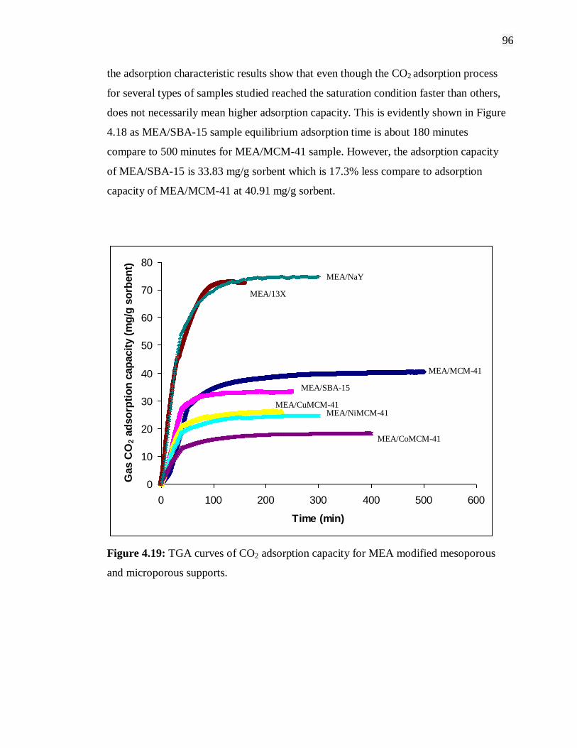
96
the adsorption characteristic results show that even though the CO2 adsorption process
for several types of samples studied reached the saturation condition faster than others,
does not necessarily mean higher adsorption capacity. This is evidently shown in Figure
4.18 as MEA/SBA-15 sample equilibrium adsorption time is about 180 minutes
compare to 500 minutes for MEA/MCM-41 sample. However, the adsorption capacity
of MEA/SBA-15 is 33.83 mg/g sorbent which is 17.3% less compare to adsorption
capacity of MEA/MCM-41 at 40.91 mg/g sorbent.
0
10
20
30
40
50
60
70
80
0 100 200 300 400 500 600
Time (min)
Gas C
O2 a
dso
rpti
on
cap
acit
y (
mg
/g s
orb
en
t)
Figure 4.19: TGA curves of CO2 adsorption capacity for MEA modified mesoporous
and microporous supports.
MEA/13X
MEA/NaY
MEA/CoMCM-41
MEA/NiMCM-41 MEA/CuMCM-41
MEA/SBA-15
MEA/MCM-41
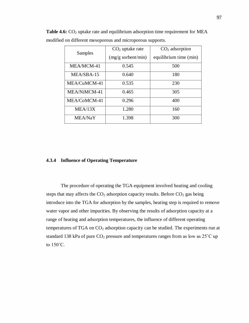
97
Table 4.6: CO2 uptake rate and equilibrium adsorption time requirement for MEA
modified on different mesoporous and microporous supports.
Samples CO2 uptake rate
(mg/g sorbent/min)
CO2 adsorption
equilibrium time (min)
MEA/MCM-41 0.545 500
MEA/SBA-15 0.640 180
MEA/CuMCM-41 0.535 230
MEA/NiMCM-41 0.465 305
MEA/CoMCM-41 0.296 400
MEA/13X 1.280 160
MEA/NaY 1.398 300
4.3.4 Influence of Operating Temperature
The procedure of operating the TGA equipment involved heating and cooling
steps that may affects the CO2 adsorption capacity results. Before CO2 gas being
introduce into the TGA for adsorption by the samples, heating step is required to remove
water vapor and other impurities. By observing the results of adsorption capacity at a
range of heating and adsorption temperatures, the influence of different operating
temperatures of TGA on CO2 adsorption capacity can be studied. The experiments run at
standard 138 kPa of pure CO2 pressure and temperatures ranges from as low as 25˚C up
to 150˚C.
98
4.3.4.1 Influence of Adsorption Temperatures
The adsorption of CO2 by porous materials or amines is an exothermic process.
Accordingly, the adsorption capacity should decrease with the increase of temperature.
However, study by Xu et al. (2002), shows otherwise that the CO2 adsorption capacity
increases with increasing temperature. In the end, it is stated that the adsorption capacity
at low temperature will eventually be larger than at high temperature if the adsorption
time is long enough to ensure that it reaches equilibrium state. As in this study, there is
no such issue as contradicting the exothermic process theory as the adsorption time is
long enough (24 hours) for the samples to reach equilibrium state with the CO2
adsorbate. The results are evidently shown in Figure 4.20, as the adsorption capacity
decreased when the temperature is increased.
The effects of different adsorption temperatures on CO2 adsorption capacity for
20 wt% MEA modified MCM-41 are presented in Figure 4.20. As expected, the CO2
adsorption capacity at adsorption temperature 25˚C (room temperature) shows the
highest value at 82.30 mg/g sorbent. When the adsorption temperature increased to
50˚C, the adsorption capacity decreased to 40.91 mg/g sorbent which is 50.3% reduced
in total amount CO2 adsorbed. When the adsorption temperature is further increased to
75˚C, the adsorption capacity is the lowest at 17.00 mg/g sorbent which is about 58%
decrease compare to amount adsorbed at 50˚C. These results indicated that for each
25˚C increment in adsorption temperature, about half of the adsorption capacity is
reduced. At higher temperature the adsorbate CO2 molecules tend to be in active
energized form and are harder to adsorb compare to molecules at lower temperature
which has lower activation energy to be adsorbed.
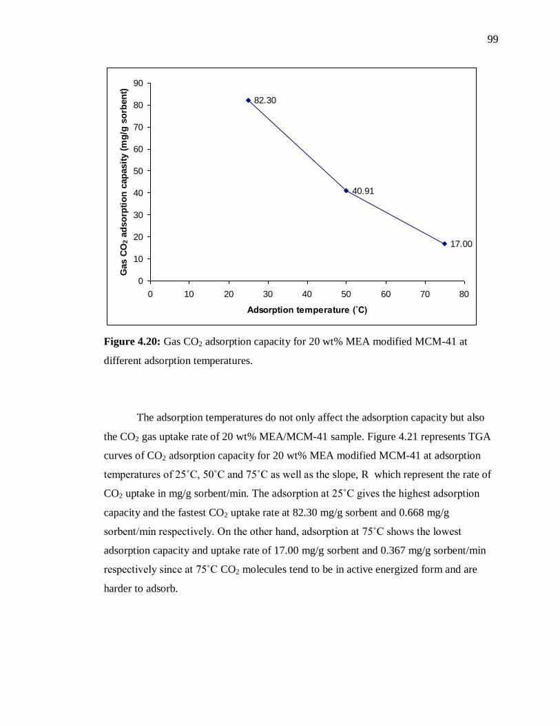
99
82.30
40.91
17.00
0
10
20
30
40
50
60
70
80
90
0 10 20 30 40 50 60 70 80
Adsorption temperature (˚C)
Gas C
O2 a
dso
rpti
on
cap
asit
y (
mg
/g s
orb
en
t)
Figure 4.20: Gas CO2 adsorption capacity for 20 wt% MEA modified MCM-41 at
different adsorption temperatures.
The adsorption temperatures do not only affect the adsorption capacity but also
the CO2 gas uptake rate of 20 wt% MEA/MCM-41 sample. Figure 4.21 represents TGA
curves of CO2 adsorption capacity for 20 wt% MEA modified MCM-41 at adsorption
temperatures of 25˚C, 50˚C and 75˚C as well as the slope, R which represent the rate of
CO2 uptake in mg/g sorbent/min. The adsorption at 25˚C gives the highest adsorption
capacity and the fastest CO2 uptake rate at 82.30 mg/g sorbent and 0.668 mg/g
sorbent/min respectively. On the other hand, adsorption at 75˚C shows the lowest
adsorption capacity and uptake rate of 17.00 mg/g sorbent and 0.367 mg/g sorbent/min
respectively since at 75˚C CO2 molecules tend to be in active energized form and are
harder to adsorb.

100
0
10
20
30
40
50
60
70
80
90
0 50 100 150 200 250
Time (min)
Gas C
O2 a
dso
rpti
on
cap
acit
y (
mg
/g s
orb
en
t)
Figure 4.21: Slope, R represent rate of CO2 uptake for 20 wt% MEA modified MCM-
41 at different adsorption temperatures.
4.3.4.2 Influence of Heating Temperatures
The water vapor content in natural gas mixtures can vary from less than 1% to
more than 10%. On the other hand, water also plays an important role of proton transfer
agent in the reaction of acidic gas and amine solutions (conventional method of
removing acidic gas from natural gas). Therefore, it is important to study the effects of
water on acidic gas adsorption (Kaggerud et al., 2006; Huang and Yang, 2003).
R=0.668
R=0.367
R=0.545
Adsorption at 75˚C
Adsorption at 50˚C
Adsorption at 25˚C
101
Huang and Yang (2003) indicated that water vapor actually enhanced CO2
adsorption on the amine modified samples. Quantitative analysis of the CO2 desorption
amount according to the peak area indicates that the amount of CO2 desorbed is twice
when the water was present during the adsorption. Their result is consistent with the fact
that the mechanism for CO2 removal using amines is dependence on the presence of
water. Two moles of amine groups are required to remove every one mol of CO2
molecules in order to form carbamate when water vapor is absent from the reaction.
Whereas one mol of amine groups is effective enough in removing one mol of CO2 to
form bicarbonate in the presence of water. The study also suggests that the CO2-amine
bonding is enhanced when water vapor is presence during the adsorption (Gray et al.,
2005; Zhou et al., 2005; Khatri et al., 2005; Huang and Yang, 2003).
Since the presence of water affects the CO2 adsorption capacity, thus it is
essential to study the effect of water vapor during gas-solid adsorption interaction. In
this study, the main purpose of applying heat to the samples through TGA equipment is
to remove impurities and water vapor in order to obtain clean adsorption on the
adsorbents. However, since the presence of water proved to be affecting the adsorption
capacity, the following experiment was designed to verify the theory. Four different
heating temperatures were applied through TGA to investigate the adsorption capacity
of 20 wt% MEA modified MCM-41 as shown in Figure 4.22.
The first heating temperature was 25˚C at room temperature. The result shows
adsorption capacity of 21.71 mg/g sorbent which is lower than standard experiment
temperature at 100˚C with high adsorption capacity of 40.91 mg/g sorbent. The same
result is obtained when heating temperature is raised to 50˚C with only a slight increase
of adsorption capacity of 23.47 mg/g sorbent. These findings clearly show that although
the presence of water does improve adsorption, but without impurities being removed
from the pore channels and surface of the adsorbents, it is impossible to achieve
maximum CO2 adsorption capacity. For the last experiment, heating temperature was

102
applied higher than water boiling point at 150˚C since even at 100˚C there still is a small
trace of water vapor trapped. This is to ensure all water vapor is removed from the
system, hence the adsorption of CO2 without the presence of water vapor is able to be
confirmed. The CO2 adsorption capacity at heating temperature of 150˚C is 33.11 mg/g
sorbent which is about 19% lower than standard at 100˚C. The result further confirm
that the presence of water vapor does contribute to CO2 adsorption capacity by amine
modified MCM-41.
21.7123.47
40.91
33.11
0
5
10
15
20
25
30
35
40
45
Without heating Heating at 50˚C Heating at 100˚C Heating at 150˚C
Gas C
O2 a
dso
rpti
on
cap
acit
y (
mg
/g s
orb
en
t)
Figure 4.22: Gas CO2 adsorption capacity for 20 wt% MEA modified MCM-41 at
different heating temperatures.
In order to study the effect of heating temperatures on CO2 uptake rate of 20
wt% MEA modified MCM-41, Figure 4.23 is presented. Surprisingly, although without
heating gives the lowest adsorption capacity, the rate of CO2 adsorption is extremely fast
(1.424 mg/g sorbent/min) compare to others. For the first 20 minutes, a total of 94%
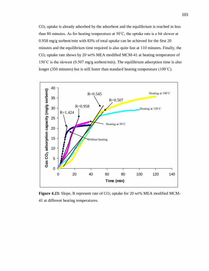
103
CO2 uptake is already adsorbed by the adsorbent and the equilibrium is reached in less
than 80 minutes. As for heating temperature at 50˚C, the uptake rate is a bit slower at
0.958 mg/g sorbent/min with 83% of total uptake can be achieved for the first 20
minutes and the equilibrium time required is also quite fast at 110 minutes. Finally, the
CO2 uptake rate shows by 20 wt% MEA modified MCM-41 at heating temperature of
150˚C is the slowest (0.507 mg/g sorbent/min). The equilibrium adsorption time is also
longer (350 minutes) but is still faster than standard heating temperature (100˚C).
0
5
10
15
20
25
30
35
40
0 20 40 60 80 100 120 140
Time (min)
Gas C
O2 a
dso
rpti
on
cap
acit
y (
mg
/g s
orb
en
t)
Figure 4.23: Slope, R represent rate of CO2 uptake for 20 wt% MEA modified MCM-
41 at different heating temperatures.
R=1.424
R=0.958
R=0.507
R=0.545
Heating at 50˚C
Without heating
Heating at 150˚C
Heating at 100˚C
104
4.4 Gas-Solid Interaction
Interaction between gas asorbate and the solid adsorbent plays an important role
in adsorption process. Therefore, it is essential to fully understand the characteristics of
interaction between the adsorbed CO2 gas molecules and the amine modified support
materials. In situ FTIR spectroscopy has been utilized for studying the adsorbed species
interaction with support materials surface directly and the transport of interacting
molecules in pores of the support materials (Rajesh et al., 2005; Zheng et al., 2005). For
this study, the amine modified samples were activated at 100˚C and vacuum at the same
time for 2 hours before the introduction of CO2 gas at various pressures. After the
adsorption of CO2 at room temperature for another 1 hour, the samples were studied by
transmission FTIR spectroscopy. Thus, the FTIR spectra acquired were the result of
solely the interaction of CO2 gas with the support surface only.
Through the study of Yang et al. (2006) regarding the interaction between CO2
molecules with silica surfaces, the fields of the minimum potential energy of a CO2
molecule over the solid surfaces were evaluated. The study involved the evaluation of
dispersion/repulsion and the electrostatic energies between the atoms in the CO2
molecules with the surface atoms which evidently showed there are bonds between CO2
molecules and the silica surface. However, the bonds do not show the obvious
characteristic peak indicating any orientation of CO2 molecules with respect to this
surface is allowed. Since there is no certain appropriate interaction directly on silica
surface, the discussion will focus on the interaction of CO2 molecules on amine
modified silica surface instead.
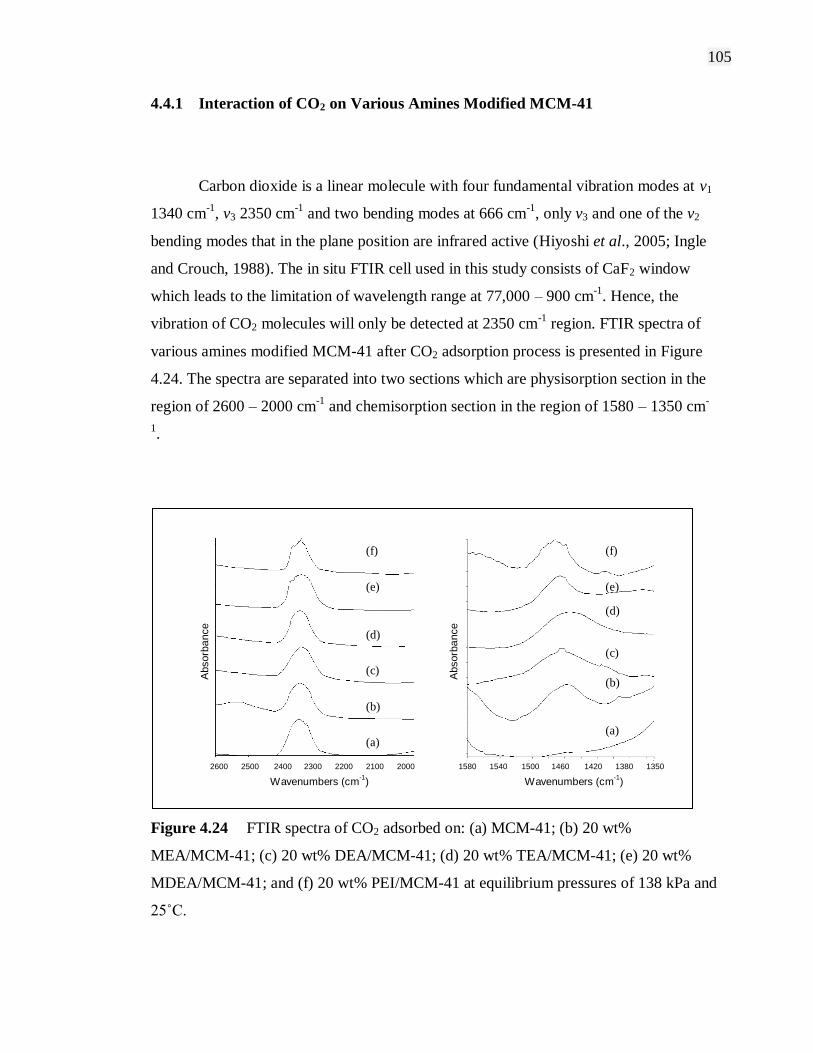
105
4.4.1 Interaction of CO2 on Various Amines Modified MCM-41
Carbon dioxide is a linear molecule with four fundamental vibration modes at v1
1340 cm-1
, v3 2350 cm-1
and two bending modes at 666 cm-1
, only v3 and one of the v2
bending modes that in the plane position are infrared active (Hiyoshi et al., 2005; Ingle
and Crouch, 1988). The in situ FTIR cell used in this study consists of CaF2 window
which leads to the limitation of wavelength range at 77,000 – 900 cm-1
. Hence, the
vibration of CO2 molecules will only be detected at 2350 cm-1
region. FTIR spectra of
various amines modified MCM-41 after CO2 adsorption process is presented in Figure
4.24. The spectra are separated into two sections which are physisorption section in the
region of 2600 – 2000 cm-1
and chemisorption section in the region of 1580 – 1350 cm-
1.
Figure 4.24 FTIR spectra of CO2 adsorbed on: (a) MCM-41; (b) 20 wt%
MEA/MCM-41; (c) 20 wt% DEA/MCM-41; (d) 20 wt% TEA/MCM-41; (e) 20 wt%
MDEA/MCM-41; and (f) 20 wt% PEI/MCM-41 at equilibrium pressures of 138 kPa and
25˚C.
Wavenumbers (cm-1
)
Absorb
ance
Absorb
ance
(a)
(b)
(c)
(d)
Wavenumbers (cm-1
)
(a)
(b)
(c)
(d)
2600 2500 2400 2300 2200 2100 2000 1580 1540 1500 1420 1380 1350 1460
0.5 A 0.3 A
(a) (a)
(b)
(c)
(c)
(b)
(d)
(d)
(e) (e)
(f) (f)

106
From Figure 4.24, the band with frequencies around 2350 cm-1
is attributed to
the v3 vibration of physisorbed CO2. It was observed that the FTIR spectra of adsorbed
CO2 in amine modified MCM-41 is similar to the CO2 band for the parent MCM-41
support. The 2350 cm-1
band in the spectra CO2 appeared at the same location for the
pure CO2 gas phase and the adsorbed physisorbed phase which further confirmed the
physisorption of CO2 molecules on the amine modified MCM-41. Meanwhile, another
broader band in the 1580 – 1350 cm-1
region was observed for all the amine modified
MCM-41 except the MCM-41 support. The peak broad band at around 1455 cm-1
represents the C-N stretching vibrations in other word the chemisorbed CO2 band. The
parent MCM-41 spectrum does not exhibit the band at 1455 cm-1
region since no amine
was detected. This clarify the 1455 cm-1
band is attributed to chemisorption of CO2
reacted with amine of the amine modified MCM-41 to form carbonates and bicarbonates
in certain circumstance (Zhao et al., 1996; Wakabayashi et al., 1997; Khatri et al., 2005;
Hiyoshi et al., 2005).
All amine modified MCM-41 and parent MCM-41 show absorption band at
2350 cm-1
region which represent physisorption of CO2 on the adsorbents as shown in
Figure 4.24. All the bands can be observed at around the same region of 2350 cm-1
.
However, the opposite happen on the chemisorption section which shows inconsistent
band and with different absorbance value. The 20 wt% TEA/MCM-41 spectrum shows
the absorption band at 1456.46 cm-1
which is slightly shifted to the lower wavelength
compares to others which are more consistent. On the other hand, the parent MCM-41
spectrum does not shows any peak at 1455 cm-1
region since there is no amine being
modified on the adsorbent. The main difference of CO2 absorption bands for different
types of amine modified MCM-41 is the peak areas corresponding to the adsorbed
species. The areas of the FTIR absorption peaks are proportional to the adsorbed amount
of CO2 as revealed in Figure 4.25. The amount of gas adsorbed for these adsorbate–
adsorbent systems were measured using gravimetric experimental technique while the
absorbance areas were measured by FTIR.
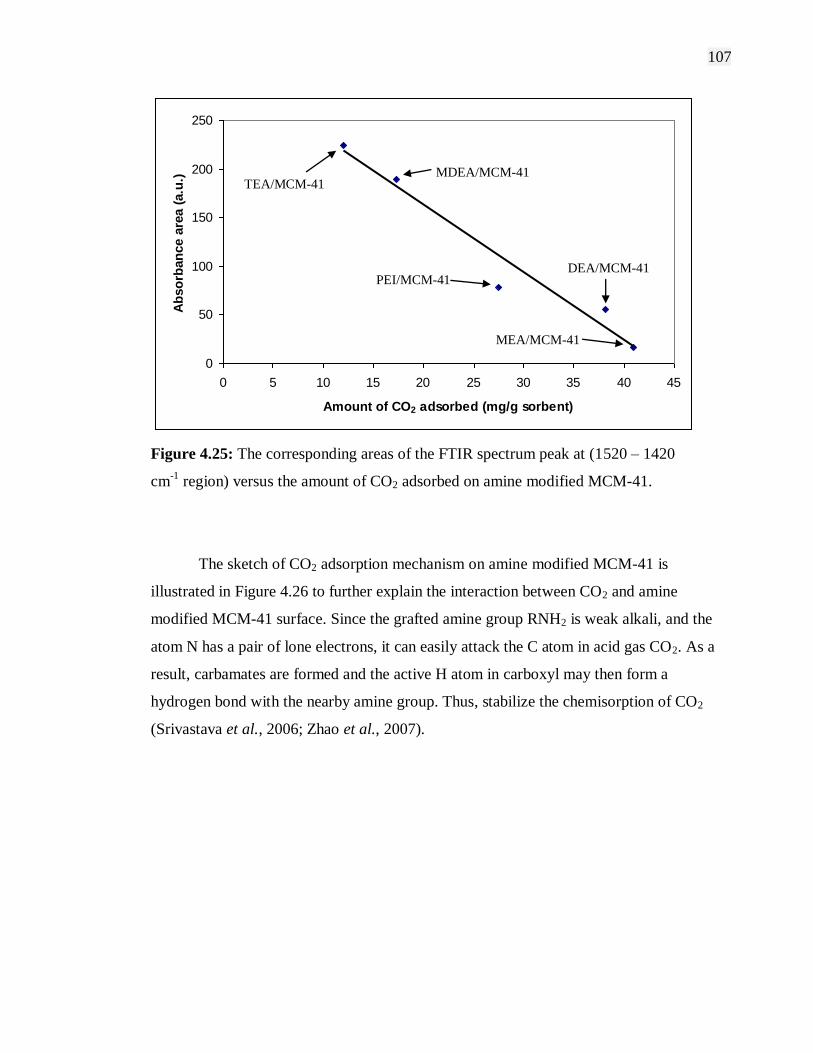
107
0
50
100
150
200
250
0 5 10 15 20 25 30 35 40 45
Amount of CO2 adsorbed (mg/g sorbent)
Ab
so
rban
ce a
rea (
a.u
.)
Figure 4.25: The corresponding areas of the FTIR spectrum peak at (1520 – 1420
cm-1
region) versus the amount of CO2 adsorbed on amine modified MCM-41.
The sketch of CO2 adsorption mechanism on amine modified MCM-41 is
illustrated in Figure 4.26 to further explain the interaction between CO2 and amine
modified MCM-41 surface. Since the grafted amine group RNH2 is weak alkali, and the
atom N has a pair of lone electrons, it can easily attack the C atom in acid gas CO2. As a
result, carbamates are formed and the active H atom in carboxyl may then form a
hydrogen bond with the nearby amine group. Thus, stabilize the chemisorption of CO2
(Srivastava et al., 2006; Zhao et al., 2007).
MDEA/MCM-41 TEA/MCM-41
PEI/MCM-41 DEA/MCM-41
MEA/MCM-41

108
Figure 4.26: Schematic diagram of CO2 adsorption on amine modified mesoporous
silica.
4.4.2 Interaction of CO2 on MEA Modified MCM-41 at Various Pressures
In order to investigate the effect of equilibrium pressure to the mechanism of
CO2 gas interaction with MCM-41 surfaces, the adsorption of CO2 molecules at room
temperature (25˚C) with increasing pressure on amine modified MCM-41 was carried
out and the results are shown in Figure 4.27. Although the absorbance of the stretching
HNH HNH
OCO
SiO2 SiO2
NH HNH
OHCO
NH HNH
OHCO
SiO2 SiO2
SiO2 SiO2
NH HNH
OHCO
SiO2 SiO2
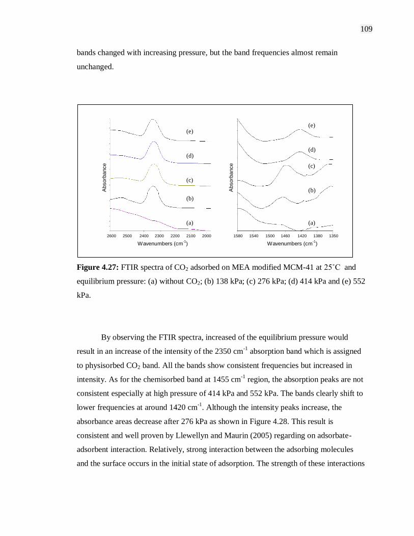
109
bands changed with increasing pressure, but the band frequencies almost remain
unchanged.
Figure 4.27: FTIR spectra of CO2 adsorbed on MEA modified MCM-41 at 25˚C and
equilibrium pressure: (a) without CO2; (b) 138 kPa; (c) 276 kPa; (d) 414 kPa and (e) 552
kPa.
By observing the FTIR spectra, increased of the equilibrium pressure would
result in an increase of the intensity of the 2350 cm-1
absorption band which is assigned
to physisorbed CO2 band. All the bands show consistent frequencies but increased in
intensity. As for the chemisorbed band at 1455 cm-1
region, the absorption peaks are not
consistent especially at high pressure of 414 kPa and 552 kPa. The bands clearly shift to
lower frequencies at around 1420 cm-1
. Although the intensity peaks increase, the
absorbance areas decrease after 276 kPa as shown in Figure 4.28. This result is
consistent and well proven by Llewellyn and Maurin (2005) regarding on adsorbate-
adsorbent interaction. Relatively, strong interaction between the adsorbing molecules
and the surface occurs in the initial state of adsorption. The strength of these interactions
Wavenumbers (cm-1
)
Absorb
ance
Absorb
ance
(a)
(b)
(c)
(d)
Wavenumbers (cm-1
)
(a)
(b)
(c)
(d)
2600 2500 2400 2300 2200 2100 2000 1580 1540 1500 1420 1380 1350 1460
0.5 A 0.3 A
(a)
(b)
(c)
(d)
(e)
(f)
(a) (a)
(b)
(b)
(c)
(c)
(d) (d)
(e) (e)

110
will then decrease (absorbance areas) as these specific sites are occupied or reached
saturation capacity.
By increasing the CO2 equilibrium pressures, the absorbance area for the
physisorption peaks also increase up to 276 kPa as shown in Figure 4.28. However,
further increase in pressure up to 414 kPa and 552 kPa shows decreasing in absorbance
area. The peak area in the 2420 – 2380 cm-1
region starting to decrease at high pressure
as the CO2 adsorption achieved saturation condition in the case of physisorption as
explained earlier. However, in the case of chemisorption, higher CO2 equilibrium
pressure applied, the more interaction between amine and CO2 molecules resulting in
more chemical reaction and higher chemisorption (Hiyoshi et al., 2000; Zheng et al.,
2005; Xu et al., 2003; Cheng et al., 2006a). This is evidently shown in Figure 4.29 as
the peak area in the 1520 – 1380 cm-1
region kept increasing with pressure increasing.
188.23
208.71 196.73
156.21
0
50
100
150
200
250
Ab
so
rban
ce a
rea (
a.u
.)
138 276 414 552
Pressure (kPa)
Figure 4.28: Effect of equilibrium CO2 pressure on the FTIR absorbance areas (2420 –
2380 cm-1
region) for the physisorption peak.

111
16.54
37.88
41.1244.34
0
5
10
15
20
25
30
35
40
45
50
Ab
so
rba
nc
e a
rea
(a
.u.)
138 276 414 552
Pressure (kPa)
Figure 4.29: Effect of equilibrium CO2 pressure on the FTIR absorbance areas (1450 –
1420 cm-1
region) for the chemisorption peak.
4.5 Summary
The structural characteristics and properties as well as carbon dioxide adsorption
characteristics of amine modified mesoporous and microporous materials have been
thoroughly studied within the scope of research. The adsorption process of porous
materials is generally depends on several parameter such as pore volume, surface area,
surface properties and the strength of adsorbate-adsorbent interactions. The
incorporation of various alkanoamines on porous materials greatly enhances the CO2
adsorption performance especially for mesoporous materials. Furthermore, the amines
also improved the CO2-adsorbent bonding and as a result increasing the selectivity of
the adsorbent towards CO2 adsorption. However, effect of amines on porous materials
112
varies differently towards mesoporous materials and microporous materials. From the
study, mesoporous materials‟ CO2 adsorption capacity improved significantly when
using monoethanolamine as the modifying agent especially on MCM-41 support. By
contrast, monoethanolamine modification on microporous materials show reduced CO2
adsorption capacity. In addition, not all amines are suitable for modification on porous
materials. Certain amines with large molecules size would actually decrease the CO2
adsorption performance of the adsorbent. Therefore, this study proved to be important in
order to understand the CO2 adsorption performance of amine modified mesoporous and
microporous materials.

CHAPTER 5
CONCLUSIONS AND RECOMMENDATIONS
5.1 Introduction
Since the findings of porous materials, studies on the general classification,
synthesis, properties and potential applications have developed significantly over the
past few years. These materials possess the ability for tailoring the surfactant assemblies
in order to be used to design novel molecular sieve materials with various engineered
structures, surface areas, pore diameters, pore size distribution and composition. Further
modifications of porous materials using organic and inorganic chemical substances have
resulted in improved performance especially when applied to gas adsorption industry
such as CO2 separation process. Through this study, modification of porous materials
using different type of amines acting as the functional group of the adsorbents greatly
influence the physical and chemical properties of the adsorbents as well as the
adsorption characteristics. This chapter review the findings obtained in this study and
give a conclusion remarks in order to completely understand CO2 adsorption
characteristics of amine modified adsorbents. Recommendations for future work are
also included for the benefit of advance research development.
114
5.2 Summary of Research Findings
Amine functional groups are useful for CO2 removal because of their ability to
form ammonium carbamates and carbonates reversibly at moderate temperature. The
incorporation of organic amines into porous supports is a great approach for CO2
adsorption combining good adsorption capacity and selectivity. Modifications of porous
materials using amines greatly influence the physicochemical properties of the porous
materials and significantly affect CO2 adsorption characteristics of the amine modified
adsorbents.
XRD equipment was used to characterize the structure of the amine modified
adsorbents. The patterns of XRD peak can be used to determine how well developed are
the as-synthesis and amine modified adsorbents. Furthermore, the intensity of the XRD
peak can explains the effect of pore filling and the coating of outer surface of amine
modified adsorbents. The nitrogen adsorption isotherms of amine modified adsorbents
can further confirm the amines were loaded into the pore channels of the support
materials. The decreased of surface area, pore volume and average pore diameter of
amine modified adsorbents can be used to explain the pore filling effect of amines.
Other than that, the FTIR spectra can also be use to characterize the amine modified
adsorbents. The stretching and bending vibration of chemical bonds will further
determined the incorporation of amines into/onto support materials.
CO2 adsorption capacity increases considerably after modification of MCM-41
using different types of alkanoamines. The ratio of CO2 molecular per available N atom
in the presence of hydroxyl group is approximately twice that without hydroxyl group.
With the absence of hydroxyl group, 2 moles of amine groups are required to react with
1 mole of CO2 molecule. However, when hydroxyl groups are present, the reaction is
two times as much leading to the formation of stabilized carbamate type zwitterions.
115
There are two possible reasons for synergetic effect determining the characteristics of
CO2 adsorption on porous materials. First is the high surface area of porous materials
and another is the uniform porous channel of porous materials. When amine was loaded
onto the materials with high surface area, there will be more CO2 affinity sites exposed
to the adsorbate and thus increasing the adsorption capacity. When the channels of
porous materials are filled by amine, the apparent pore size of the parent support will be
reduced. Hence, reducing the pore volume and decreasing the maximum CO2 adsorption
capacity. However, at the same time more CO2 affinity sites are introduced into the pore
channel of porous materials. Both these contradicting effects occurred simultaneously
and directly affected the adsorption capacity. In the study, MEA modified MCM-41
shows the highest CO2 adsorption capacity at 40.91 mg/g sorbent while the lowest
adsorption was at 12.04 mg/g sorbent by TEA modified MCM-41 sample.
MEA amine had been used to modify MCM-41 support at different
concentrations. As a result, at low MEA loading (10 wt%), the amine had little
contribution on CO2 adsorption capacity. The highest adsorption capacity was reached
by 20 wt% of MEA with high CO2 adsorption capacity at 40.91 mg/g sobent which is
120% higher than the parent MCM-41 support. The pore channels of MCM-41 play an
important role on the characteristic of CO2 adsorption capacity. When the channels of
the MCM-41 are filled with MEA, the apparent pore size of the MCM-41 will be
decreased. At the same time, more CO2 affinity sites are introduced into the channel. In
the case of MEA modified MCM-41, physisorption and chemisorption take place at the
same time. The physisorption on the MEA/MCM-41 sample occurs mainly in the pore
channels of MCM-41 support, while the chemisorption involves the reaction of CO2 and
MEA in the channels of MCM-41 as well as on the external surface of MCM-41. When
the channels of MCM-41 are fully filled with MEA, the highest adsorption capacity can
be obtained. When MEA concentration is further increased and the MEA begin to coat
on the external surface of MCM-41, the adsorption capacity decreases.
116
Through this study, microporous supports of NaY and 13X show significantly
higher CO2 adsorption capacity compared to mesoporous materials. This can be
explained as materials with the strongest enthalpic interactions with sorbed molecules
will show the highest level of adsorption. These tend to be materials with narrow pores
(microporous), because small pores increase the interaction between gas and the
framework. However, materials with narrow pores also have the highest framework
densities and thus the lowest amount of free void space per gram of material. Therefore,
at the highest pressure when the pores are nearly filled, the materials with the largest
free volumes have more room for quest molecules and consequently show the highest
CO2 uptake. This also explained why upon modification by MEA, microporous supports
NaY and 13X resulted in decrease of CO2 adsorption capacity unlike for mesoporous
supports.
The adsorption of CO2 by porous materials or amines is an exothermic process.
Accordingly, the adsorption capacity decrease with the increase of temperature. The
CO2 adsorption capacity at adsorption temperature 25˚C (room temperature) shows the
highest value at 82.30 mg/g sorbent. At higher temperature the adsorbate CO2 molecules
tend to be in active energized form and are harder to adsorb compare to molecules at
lower temperature which has lower activation energy to be adsorbed.
Interactions between CO2 molecules adsorbed on the amine modified adsorbents
are important in adsorption process. The integrated absorbance areas and the intensities
of FTIR spectrums reveal that gas CO2 interact with amine modified adsorbents. The
CO2 molecule is free rotating and adsorbed (physically and chemically) on the active
adsorption sites on adsorbent surfaces as gas phase molecules. The type of amines and
the equilibrium pressure of CO2 adsorbate have high influence on the adsorption
especially chemisorption.
117
5.3 Recommendations for Future Work
In order to further understand the gas adsorption characteristics in amine
modified adsorbents, the following recommendations are highlighted for future work.
As for structural and properties characterization, Temperature Programmed Desorption
(TPD) characterization is highly recommended to obtain the acidity and basicity
properties of amine modified adsorbents. Other than that, MAS-NMR Spectroscopy can
be use to determine the framework of Si to Al ratio by observing the high-resolution
spectra from the solid samples.
Besides that, the gas adsorption isotherms for amine modified adsorbents can be
conducted in a wider range of pressure and temperature in order to obtain clearer picture
of gas adsorption characteristics and equilibrium model. Meanwhile, in spite of using a
single pure adsorbate system, gas mixture adsorption can be carried out to further study
the adsorbents selectivity properties.
5.4 Concluding Remarks
Gas adsorption characteristics of amine modified adsorbents have been
successively studied in this work from the aspects of characterization, adsorption
equilibrium, and adsorption behavior on the gas-porous materials interaction
mechanisms. The results from this study provide a significant contribution in designing
amine modified adsorbents system for improvement towards development of new
adsorbents with the highest quality and efficiency.
REFERENCES
Anon. (2005). AG Foundation Release Natural Gas Outlook to 2020. Pipeline and Gas
Journal. 232: 6-9.
Astala, R. and Auerbach, S. M. (2004). The Properties of Methylene- and Amine-
Substituted Zeolites from First Principles. J. Am. Chem. Soc. 126: 1843-1848.
Barton, T. J., Bull, L. M., Klemperer, W. G., Loy, D. A., McEnaney, B., Misono, M.,
Monson, P. A., Pez, G., Scherer, G. W., Vartuli, J. C., and Yaghi, O. M. (1999).
Tailored Porous Materials. Chem. Mater. 11: 2633-2656.
Beck, J. S. and Vartuli, J. C. (1996). Recent Advances in The Synthesis,
Characterization and Applications of Mesoporous Molecular Sieves. Current
Opinion in Solid State & Materials Science. 1: 76-87.
Boger, T., Roesky, R., Gläser, R., Ernst, S., Eigenberger, G., and Weitkamp, J. (1997).
Influence of The Aluminum Content on The Adsorptive Properties of MCM-41.
Micropor. Mater. 8: 79-91.
Burleigh, M. C., Markowitz, M. A., Spector, M. S., and Gaber, B. P. (2001). Amine-
Functionalized Periodic Mesoporous Organosilicas. Chem. Mater. 13: 4760-4766.
Cheng, Q., Pavlinek, V., Lengalova, A., Li, C., He, Y., and Saha, P. (2006b).
Conducting Polypyrrole Confined in Ordered Mesoporous Silica SBA-15 channels:
Preparation and Its Electrorheology. Micropor. Mesopor. Mater. : 263-269.

120
Cheng, Q., Pavlinek, V., Li, C., Lengalova, A., He, Y., and Saha, P. (2006a). Synthesis
and Characterization of New Mesoporous Material with Conducting Polypyrrole
Confined in Mesoporous Silica. Mater. Chem. Phys. 98: 504-508.
Chhatwal, G. R. and Mehra, H. (1974). Adsorption and Phase Rule. India: Goel
Publishing House.
Choma, J., Jaroniec, M., Burakiewicz-Mortka, W., and Kloske, M. (2002). Critical
Appraisal of Classical Methods for Determination of Mesoporous Size Distributions
of MCM-41 Materials. Applied Surface Sci. 196: 216-223.
Choma, J., Kloske, M., and Jaroniec, M. (2003). An Improved Methodology for
Adsorption Characterization of Unmodified and Modified Silica Gels. J. Colloid and
Interface Sci. 266: 168-174.
Coade, R. and Coldham, D. (2006). The Interaction of Mercury and Aluminum in Heat
Exchangers in a Natural Gas Plants. Inter. J. Pressure Vessels and Piping. 83: 336-
342.
Dabrowski, A. (2001). Adsorption- From Theory to Practice. Adv. Colloid Interface Sci.
93: 135-224.
Daiminger, U., Lind, W., and Mitariten, M. (2004). Adsorption Added Value.
Hydrocarbon Eng. VII. 2: 83-86.
Delaney, W. S., Knowles, G. P., and Chaffee, A. L. (2002). Preprints of Symposia-
American Chemical Society, Division of Fuel Chemistry. 47(1): 65-66.
Derouane, E. G. (1998). Zeolites as Solid Solvents. J. Molecular Catal. A: Chem. 134:
29-45.

121
Desideri, U. and Paolucci, A. (1999). Performance Modelling of A Carbon Dioxide
Removal System for Power Plants. Energy Convers. Mgmt. 40: 1899-1915.
de Sousa, A. and de Sousa, E. M. B. (2005). Ordered Mesoporous Silica Carrier System
Applied in Nanobiothecnology. Brazilian Arch. Bio. Tech. 48: 243-250.
Evans, J., Zaki, A. B., El-Sheikh, M. Y., and El-Safty, S. A. (2000). Incorporation of
Transition-Metal Complexes in Functionalized Mesoporous Silica and Their
Activity toward the Oxidation of Aromatic Amines. J. Phys. Chem. B. 104: 10271-
10281.
Fajula, F., Galarneau, A. and Renzo, F. D. (2005). Advanced Porous Materials: New
Developments and Emerging Trends. Micropor. Mesopor. Mater. 82.
Frost, H., Duren, T., and Suurr R. Q. (2006). Effects of Surface Area, Free Volume, and
Heat of Adsorption on Hydrogen Uptake in Metal-Organic Frameworks. J. Phys.
Chem. B. 110: 9565-9570.
Fulvio, P. F., Pikus, S., and Jaroniec, M. (2005). Short-Time Synthesis of SBA-15 Using
Various Silica Sources. J. Colloid Interface Sci. 287: 717-720.
Gaydhankar, T. R., Taralkar, U. S., Jha, R. K., Joshi, P. N., and Kumar, R. (2005).
Textural/Structural, Stability and Morphological Properties of Mesostructured
Silicas (MCM-41 and MCM-48) Prepared Using Different Silica Sources. Catal.
Communications. 6: 361-366.
Ghobarkar, H., Schaf, O., and Guth, U. (1999). Zeolites- From Kitchen to Space. Prog.
Solid St. Chem. 27: 29-73.
122
Gray, M. L., Soong, Y., Champagne, K. J., Pennline, H., Baltrus, J. P., Stevens Jr., R.
W., Khatri, R.,Chuang, S. S. C., and Filburn, T. (2005). Improved Immobilized
Carbon Dioxide Capture Sorbents. Fuel Proc. Tech. 86: 1449-1455.
Guli, M., Chen, Y., Li, X. T., Zhu, G. S., and Qiu, S. L. (2007). Fluorescence of
Postgrafting Rhodamine B in the Mesopores of Rodlike SBA-15. J. Luminescence.
126: 723-727.
Guo, J., Han, A. J., Yu, H., Dong, J. P., He, H., and Long, Y. C. (2006). Base Property
of High Silica MFI Zeolites Modified With Various Alkyl Amines. Micropor.
Mesopor. Mater. 166-172.
Hadi Nur, Lau, C. G., Salasiah Endud, and Halimaton Hamdan. (2004). Quantitative
Measurement of A Mixture of Mesophases Cubic MCM-48 and Hexagonal MCM-
41 by 13
C CP/MAS NMR. Mater. Lett. 58: 1971-1974.
Han, A. J., He, H. Y., Guo, J., Yu, H., Huang, Y. F., and Long, Y. C. (2005). Studies on
Structure and acid-base Properties of High Silica MFI-Type Zeolite Modified with
Methylamine. Micropor. Mesopor. Mater. 79: 177-184.
Hiyoshi, N., Yogo, K., and Yashima, T. (2005). Adsorption Characteristics of Carbon
Dioxide on Organically Functionalized SBA-15. Micropor. Mesopor. Mater. 84:
357-365.
Huang, H. Y. and Yang, R. T. (2003). Amine-Grafted MCM-48 and Silica Xerogel as
Superior Sorbents for Acidic Gas Removal from Natural Gas. Ind. Eng. Chem. Res.
42: 2427-2433.
Ingle, J. D. and Crouch, S. R. (1988). Spectrochemical Analysis. United States of
America: Prentice-Hall International Inc. 404.
123
Inoue, M., Tanino, H., Kondo, Y., and Inui, T. (1991). Formation of Organic
Derivatives of Boehmite by the Reaction of Gibbsite with Glycols and
Aminoalcohols. Clays and Clay Minerals. 39(2): 151-157.
Jaroniec, M., Kruk, M., Hyun, J. S., Ryong, R., Sakamoto, Y., and Terasaki, O. (2001).
Comprehensive Characterization of Highly Ordered MCM-41 Silicas Using
Nitrogen Adsorption, Thermogravimetry, X-ray Diffraction and Transmission
Electron Microscopy. Micropor. Mesopor. Mater. 48: 127-134.
Kaggerud, K. H., Bolland, O., and Gundersen, T. (2006). Chemical and Process
Integration: Synergies in Co-Production of Power and Chemicals from Natural Gas
With CO2 Capture. Applied Thermal Eng. 26: 1345-1352.
Kang, T., Park, Y., Park, J. C., Cho, Y. S., and Yi, J. (2002). Preparation of Chemically
Active Mesoporous Adsorbent for Pt(II) and Pd(II) Adsorption from Aqueous
Solutions. Korean J. Chem. Eng. 19(4): 685-687.
Khatri, R. A., Chuang, S. S. C., Soong, Y., and Gray, M. (2005). Carbon Dioxide
Capture by Diamine-Grafted SBA-15: A Combined Fourier Transform Infrared and
Mass Spectrometry Study. Ind. Eng. Chem. Res. 44: 3702-3708.
Klimova, T., Esquivel, A., Reyes, J., Rubio, M., Bokhimi, X., and Aracil, J. (2006).
Factorial Design for the Evaluation of the Influence of Synthesis Parameters Upon
The Textural and Structural Properties of SBA-15 Ordered Materials. Micropor.
Mesopor. Mater. 331-343.
Knowles, G. P., Graham, J. V., Delaney, S. W., and Chaffee, A. L. (2005).
Aminopropyl-Functionalized Mesoporous Silicas as CO2 Adsorbent. Fuel Proc.
Tech. 86: 1435-1448.
124
Kruk, M. and Jaroniec, M. (2001). Characterization of Modified Mesoporous Silicas
Using Argon and Nitrogen Adsorption. Micropor. Mesopor. Mater. 44-45: 725-732.
Kruk, M., Jaroniec, M., and Sayari, A. (1999). Influence of Hydrothermal Restructuring
Conditions on Structural Properties of Mesoporous Molecular Sieves. Micropor.
Mesopor. Mater. 27: 217-229.
Kumar, D., Schumacher, K., Hohenesche, D. F. V., Grün, M., and Unger, K. K. (2001).
MCM-41, MCM-48 and Related Mesoporous Adsorbents: Their Synthesis and
Characterisation. Colloids and Surfaces A: Physicochem. Eng. Aspects. 187-188:
109-116.
Lee, S. H., Lee, J. Y., Park, Y. M., Wee, J. H., and Lee, K. Y. (2006). Complete
Oxidation of Methane and CO at Low Temperature over LaCoO3 Prepared by
Spray-freezing/Freeze-drying Method. Catal. Today. In press.
Llewellyn, P. L. and Maurin, G. (2005). Gas Adsorption Microcalorimetry and
Modeling to Characterise Zeolites and Related Materials. C. R. Chimie. 8: 283-302.
Luan, Z. and Fournier, J. A. (2005). In Situ FTIR Spectroscopic Investigation of Active
Sites and Adsorbate Interactions in Mesoporous Aluminosilicate SBA-15 Molecular
Sieves. Micropor. Mesopor. Mater. 79: 235-240.
Luan, Z., Fournier, J. A., Wooten, J. B., and Miser, D. E. (2005). Preparation and
Characterization of (3-aminopropyl)triethoxysilane-Modified Mesoporous SBA-15
Silica Molecular Sieves. Micropor. Mesopor. Mater. 83: 150-158.
Mavrakis, D., Thomaidis, F., and Ntroukas, I. (2006). An Assessment of the Natural Gas
Supply Potential of the South Energy Corridor from the Caspian Region to the EU.
Energy Policy. 34: 1671-1680.
125
McKittrick, M. W. and Jones, C. W. (2003). Toward Single-Site Functional Materials-
Preparation of Amine-Functionalized Surfaces Exhibiting Site-Isolated Behavior.
Chem. Mater. 15: 1132-1139.
Meisen, A. and Shuai, X. S. (1997). Research and Development Issues in CO2 Capture.
Energy Convers. Mgmt. 38: 837-842.
Mercuri, L. P., Matos, J. R., Li, Z., and Jaroniec, M. (2006). Comparative
Thermogravimetric and Adsorption Study of Highly Ordered Mesoporous Materials.
J. Colloid Interface Sci. 296: 377-380.
Mirji, S. A., Halligudi, S. B., Mathew, N., Jacob, N. E., Patil, K. R., and Gaikwad, A. B.
(2006). Adsorption of Methanol on Mesoporous SBA-15. Mater. Lett.
Murcia, A. B., Fletcher, A. J., Martinez, J. G., Amoros, D. C., Solano, A. L., and
Thomas, K. M. (2003). Probe Molecule Kinetic Studies of Adsorption on MCM-41.
J. Phys. Chem. B. 107: 1012-1020.
Náray-Szabó, I. (1969). Inorganic Crystal Chem. Hungary: Akadémiai Kiadó, Budapest.
Parvulescu, V. and Su, B. L. (2001). Iron, Cobalt or Nickel Substituted MCM-41
Molecular Sieves for Oxidation of Hydrocarbon. Catal. Today. 69: 315-322.
Philippe, L., Sammon, C., Lyon, S. B., and Yarwood, J. (2004a). An FTIR/ATR in Situ
Study of Sorption and Transport in Corrosion Protective Organic Coatings 1. Water
Sorption and Role of Inhibitor Anions. Prog. Org. Coatings. 49: 302-314.
Philippe, L., Sammon, C., Lyon, S. B., and Yarwood, J. (2004b). An FTIR/ATR in Situ
Study of Sorption and Transport in Corrosion Protective Organic Coatings 2. The
Effects of Temperature and Isotop Dilution. Prog. Org. Coatings. 49: 315-323.
126
Rege, S. U. and Yang, R. T. (2001). A Novel FTIR Method for Studying Mixed Gas
Adsorption at Low Concentrations: H2O and CO2 on NaX Zeolite and γ-alumina.
Chem. Eng. Sci. 56: 3781-3796.
Sherman, J. D. (1999). Synthetic Zeolites and Other Microporous Oxide Molecular
Sieves. Proc. Natl. Acad. Sci. 96: 3471-3478.
Sing, K. S. W. (1998). Adsorption Methods for the Characterization of Porous
Materials. Adv. Colloid Interface Sci. 76-77: 3-11.
Sing, K. (2001). The Use of Nitrogen Adsorption for the Characterization of Porous
Materials. Colloid and Surface A: Physicochem. Eng. Aspects. 187-188: 3-9.
Sing, K. S. W. (2004). Characterization of Porous Materials: Past, Present and Future.
Colloid and Surface A: Physicochem. Eng. Aspects. 241: 3-7.
Srivastava, R., Srinivas, D., and Ratnasamy, P. (2006). Sites for CO2 Activation Over
Amine-Functionalized Mesoporous Ti(Al)-SBA-15 Catalysts. Micropor. Mesopor.
Mater. 90: 314-326.
Stucky, G. D., Zhao, D. Y., Feng, J. L., Huo, Q. S., Melosh, N., Fredrickson, G. H., and
Chmelka, B. F. (1998). Triblock Copolymer Syntheses of Mesoporous Silica with
Periodic 50 to 300 Angstrom Pores. Sci. 279: 548-552.
Tallon, C., Yates, M., Moreno, R., and Nieto, M. I. (2006a). Porosity of Freeze-dried γ-
Al2O3 Powders. Ceramics Inter. In press.
Tallon, C., Moreno, R., and Nieto, M. I. (2006b). Synthesis of γ-Al2O3 Nanopowders by
Freeze-drying. Mater. Research Bulletin. 41: 1520-1529.
127
Thommes, M., Köhn, R., and Fröba, M. (2002). Sorption and Pore Condensation
Behavior of Pure Fluids in Mesoporous MCM-48 Silica, MCM-41 Silica, SBA-15
Silica and Controlled-Pore Glass at Temperatures Above and Below The Bulk Triple
Point. Applied Surface Sci. 196: 239-249.
Ustinov, E. A., Do, D. D., and Jaroniec, M. (2005). Adsorption of Argon and Nitrogen
in Cylindrical Pores of MCM-41 Materials: Application of Density Functional
Theory. Applied Surface Sci.
Vartuli, J. C., Malek, A., Roth, W. J., Kresge, C. T., and McCullen, S. B. (2001). The
Sorption Properties of As-Synthesized and Calcined MCM-41 and MCM-48.
Micropor. Mesopor. Mater. 44-45: 691-695.
Wakabayashi, F., Kondo, J. N., Domen, K., and Hirose, C. (1997). FT-IR Study of The
Interaction of Oxygen, Argon, Helium, Nitrogen and Xenon With Hydroxyl Groups
in H-Y Zeolite at Low Temperatures. Micropor. Mater. 8: 29-37.
Weitkamp, J. (2000). Zeolites and Catalysis. Solid State Ionics. 131: 175-188.
Xiao, B. L., Wang, H., and He, R. (2002). Aluminum Phthalocyanine Complex
Covalently Bonded to MCM-41 Silica as Heterogeneous Catalyst for the Synthesis
of Cyclic Carbonates. J. Molecular Catal. A: Chem. 186: 33-42.
Xu, X., Song, C., Andresen, J. M., Miller, B. G., and Scaroni, A. W. (2002). Novel
Polyethylenimine-Modified Mesoporous Molecular Sieve of MCM-41 Type as
High-Capacity Adsorbent for CO2 Capture. Energy & Fuels. 16: 1463-1469.
Xu, X., Song, C., Andrésen, J. M., Miller, B. G., and Scaroni, A. W. (2003). Preparation
and Characterization of Novel CO2 “Molecular Basket” Adsorbents Based on
Polymer-Modified Mesoporous Molecular Sieve MCM-41. Micropor. Mesopor.
Mater. 62: 29-45.

128
Yang, X. N., Xu, Z. J., and Zhang, C. J. (2006). Molecular Dynamics Simulation of
Dense Carbon Dioxide Fluid on Amorphous Silica Surfaces. J. Colloid Interface Sci.
297: 38-44.
Xu, X., Song, C., Miller, B. G., and Scaroni, A. W. (2005). Adsorption Separation of
Carbon Dioxide from Flue Gas of Natural Gas-Fired Boiler by A Novel Nanoporous
“Molecular Basket” Adsorbent. Fuel Proc. Tech. 86: 1457-1472.
Zhang, X., Schubert, S., and Agar, D. W. (2005). Studies on the Kinetics of Carbon
Dioxide Absorption with Immobilised Amines (IA). Chem. Eng. J. 107: 97-102.
Zhao, H. L., Hu, J., Wang, J. J., Zhou, L. H., and Liu, H. L. (2007). CO2 Capture by the
Amine-Modified Mesoporous Materials. Acta Phys. –Chim. Sin. 23(6): 801-806.
Zhao, X. S., Lu, G. Q., and Hu, X. (2000). Characterization of the Structural and Surface
Properties of Chemically Modified MCM-41 Material. Micropor. Mesopor. Mater.
41: 37-47.
Zhao, X. S., Lu, G. Q., and Hu, X. (2001). Organophilicity of MCM-41 Adsorbents
Studied by Adsorption and Temperature-Programmed Desorption. Colloids and
Surfaces A: Physicochem. Eng. Aspects. 179: 261-269.
Zhao, X. S., Lu, G. Q., and Millar, G. J. (1996). Advances in Mesoporous Molecular
Sieve MCM-41. Ind. Eng. Chem. Res. 35: 2075-2090.
Zheng, F., Tran, D. N., Busche, B. J., Fryxell, G. E., Addleman, R. S., Zemanian, T. S.,
and Aardahl, C. L. (2005). Ethylenediamine-Modified SBA-15 as Regenerable CO2
Sorbent. Ind. Eng. Chem. Res. 44: 3099-3105.
129
Zhou, L., Liu, X., Sun, Y., Li, J., and Zhou, Y. (2005). Methane Sorption in Ordered
Mesoporous Silica SBA-15 in The Presence of Water. J. Phys. Chem. B. 109:
22710-22714.
Zhu, S. M., Zhou, H. S., Hibino, M., and Honma, I. (2003). Metallic Ruthenium
Incorporation in the Porous Structure of SBA-15 Using a Sonochemical method. J.
Mater. Chem. 13: 1115-1118.
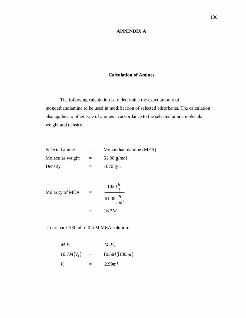
130
APPENDIX A
Calculation of Amines
The following calculation is to determine the exact amount of
monoethanolamine to be used in modification of selected adsorbents. The calculation
also applies to other type of amines in accordance to the selected amine molecular
weight and density.
Selected amine = Monoethanolamine (MEA)
Molecular weight = 61.08 g/mol
Density = 1020 g/L
Molarity of MEA =
mol
gl
g
08.61
1020
= M7.16
To prepare 100 ml of 0.5 M MEA solution:
11VM = 22VM
17.16 VM = mlM 1005.0
1V = ml99.2

131
= ml
gml 02.199.2
g05.3
To calculate 20 wt% of MEA:
Total adsorbent weight = 0.5 g
Weight of MEA = 20 % x 0.5 g
= 0.1 g
The rest of the adsorbent is MCM-41 = 0.5 g – 0.1 g
= 0.4 g
From previous calculation we know that there are 3.05 g of MEA in 100 ml of
0.5 M MEA solution. Therefore, to obtain 0.1 g of MEA, the volume of 0.5 M MEA
solution need to add to 0.4 g of MCM-41 is:
g05.3 ml100
g1.0 g
mlg
05.3
1001.0
ml28.3
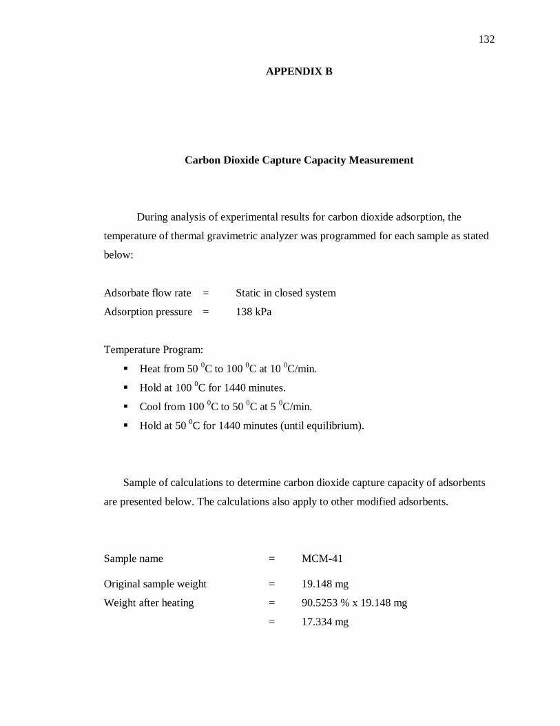
132
APPENDIX B
Carbon Dioxide Capture Capacity Measurement
During analysis of experimental results for carbon dioxide adsorption, the
temperature of thermal gravimetric analyzer was programmed for each sample as stated
below:
Adsorbate flow rate = Static in closed system
Adsorption pressure = 138 kPa
Temperature Program:
Heat from 50 0C to 100
0C at 10
0C/min.
Hold at 100 0C for 1440 minutes.
Cool from 100 0C to 50
0C at 5
0C/min.
Hold at 50 0C for 1440 minutes (until equilibrium).
Sample of calculations to determine carbon dioxide capture capacity of adsorbents
are presented below. The calculations also apply to other modified adsorbents.
Sample name = MCM-41
Original sample weight = 19.148 mg
Weight after heating = 90.5253 % x 19.148 mg
= 17.334 mg
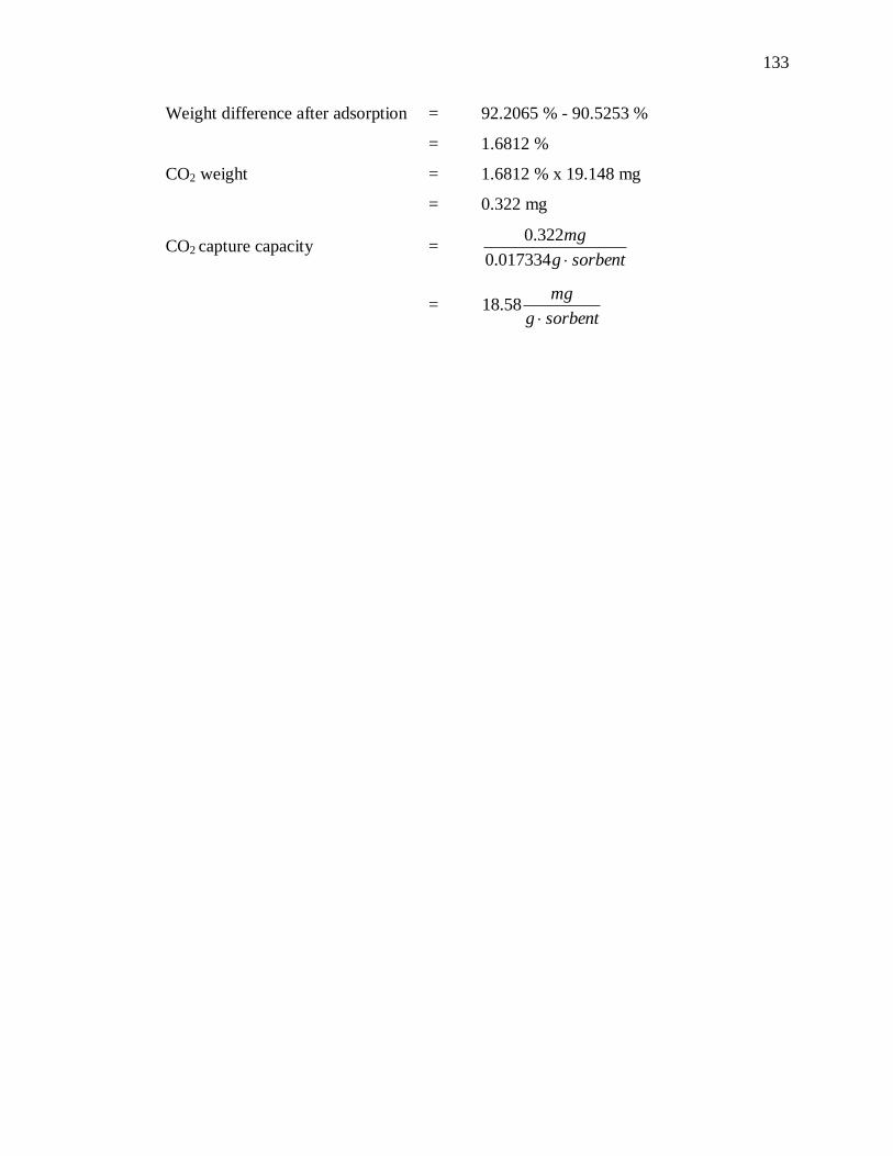
133
Weight difference after adsorption = 92.2065 % - 90.5253 %
= 1.6812 %
CO2 weight = 1.6812 % x 19.148 mg
= 0.322 mg
CO2 capture capacity = sorbentg
mg
017334.0
322.0
= sorbentg
mg
58.18