SYNTHESIS AND CHARACTERIZATION OF ALKYLZIRCONIUM COMPLEXES...
140
1 SYNTHESIS AND CHARACTERIZATION OF ALKYLZIRCONIUM COMPLEXES FOR THE FABRICATION OF LOW WORK FUNCTION MATERIALS AND SYNTHESIS OF HYDANTOINS AND DIHYDROURACILS FROM AMINO AMIDES By SETH MICHAEL DUMBRIS A DISSERTATION PRESENTED TO THE GRADUATE SCHOOL OF THE UNIVERSITY OF FLORIDA IN PARTIAL FULFILLMENT OF THE REQUIREMENTS FOR THE DEGREE OF DOCTOR OF PHILOSOPHY UNIVERSITY OF FLORIDA 2010
Transcript of SYNTHESIS AND CHARACTERIZATION OF ALKYLZIRCONIUM COMPLEXES...

1
SYNTHESIS AND CHARACTERIZATION OF ALKYLZIRCONIUM COMPLEXES FOR THE FABRICATION OF LOW WORK FUNCTION MATERIALS AND SYNTHESIS OF
HYDANTOINS AND DIHYDROURACILS FROM AMINO AMIDES
By
SETH MICHAEL DUMBRIS
A DISSERTATION PRESENTED TO THE GRADUATE SCHOOL OF THE UNIVERSITY OF FLORIDA IN PARTIAL FULFILLMENT
OF THE REQUIREMENTS FOR THE DEGREE OF DOCTOR OF PHILOSOPHY
UNIVERSITY OF FLORIDA
2010

2
© 2010 Seth Michael Dumbris

3
To SDG and to my loving wife, Molly
4
ACKNOWLEDGMENTS
I would like to thank my parents, Alan and Linda Dumbris, and siblings for their
encouragement over the years. I would also like to thank my colleagues whom I have
worked with in the McElwee-White laboratories, especially Phillip Shelton, Ampofo
Darko, and Jennifer Johns. I would also like to thank Dr. Khalil Abboud and Jürgen
Kohler for their assistance with the X-ray crystallography and Dempsey Hyatt for
computational assistance.
5
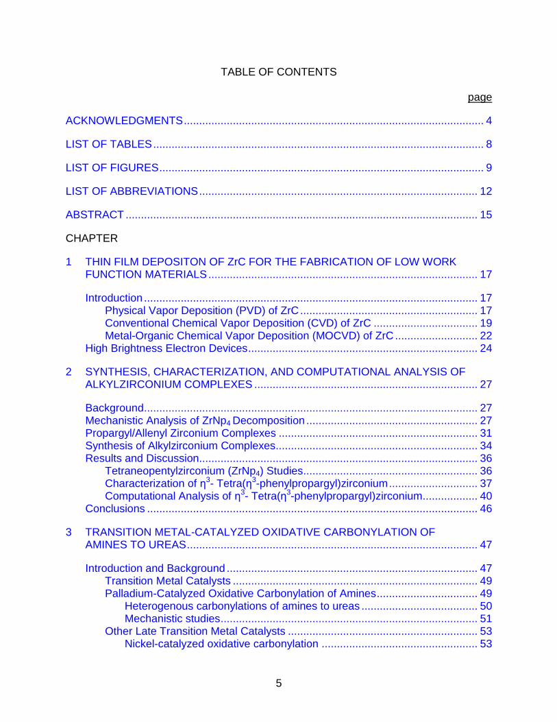
TABLE OF CONTENTS page
ACKNOWLEDGMENTS .................................................................................................. 4
LIST OF TABLES ............................................................................................................ 8
LIST OF FIGURES .......................................................................................................... 9
LIST OF ABBREVIATIONS ........................................................................................... 12
ABSTRACT ................................................................................................................... 15
CHAPTER
1 THIN FILM DEPOSITON OF ZrC FOR THE FABRICATION OF LOW WORK FUNCTION MATERIALS ........................................................................................ 17
Introduction ............................................................................................................. 17 Physical Vapor Deposition (PVD) of ZrC .......................................................... 17 Conventional Chemical Vapor Deposition (CVD) of ZrC .................................. 19
Metal-Organic Chemical Vapor Deposition (MOCVD) of ZrC ........................... 22 High Brightness Electron Devices ........................................................................... 24
2 SYNTHESIS, CHARACTERIZATION, AND COMPUTATIONAL ANALYSIS OF ALKYLZIRCONIUM COMPLEXES ......................................................................... 27
Background ............................................................................................................. 27 Mechanistic Analysis of ZrNp4 Decomposition ........................................................ 27 Propargyl/Allenyl Zirconium Complexes ................................................................. 31
Synthesis of Alkylzirconium Complexes.................................................................. 34 Results and Discussion........................................................................................... 36
Tetraneopentylzirconium (ZrNp4) Studies ......................................................... 36 Characterization of η3- Tetra(η3-phenylpropargyl)zirconium ............................. 37 Computational Analysis of η3- Tetra(η3-phenylpropargyl)zirconium .................. 40
Conclusions ............................................................................................................ 46
3 TRANSITION METAL-CATALYZED OXIDATIVE CARBONYLATION OF AMINES TO UREAS ............................................................................................... 47
Introduction and Background .................................................................................. 47
Transition Metal Catalysts ................................................................................ 49 Palladium-Catalyzed Oxidative Carbonylation of Amines ................................. 49
Heterogenous carbonylations of amines to ureas ...................................... 50 Mechanistic studies .................................................................................... 51
Other Late Transition Metal Catalysts .............................................................. 53 Nickel-catalyzed oxidative carbonylation ................................................... 53

6
Ruthenium-catalyzed oxidative carbonylation ............................................ 54
Cobalt- and rhodium-catalyzed oxidative carbonylation ............................. 55 Gold-catalyzed oxidative carbonylation ...................................................... 59
Tungsten-Catalyzed Oxidative Carbonylation of Amines ................................. 60 Carbonylation of primary amines ............................................................... 60 Carbonylation of primary and secondary diamines to cyclic ureas ............. 63
Conclusions ............................................................................................................ 73
4 CATALYTIC OXIDATIVE CARBONYLATION OF α-AMINO AMIDES TO PRODUCE HYDANTOIN DERIVATIVES ............................................................... 74
Background ............................................................................................................. 74 Classic Ways to Synthesize Hydantoins ................................................................. 74
Solution Phase Syntheses................................................................................ 76
Solid Phase Syntheses..................................................................................... 78 Synthesis of α-Amino Amides ................................................................................. 79
Results and Discussion........................................................................................... 82 Conclusions ............................................................................................................ 87
5 CATALYTIC OXIDATIVE CARBONYLATION OF β-AMINO AMIDES TO PRODUCE 5,6-DIHYDROURACIL DERIVATIVES ................................................ 88
Background ............................................................................................................. 88
Synthetic Routes to Form Dihydrouracils ................................................................ 88 Solution Phase Methods................................................................................... 89
Solid Phase Organic Chemistry (SPOC) .......................................................... 93
Synthesis of β-Amino Amides ................................................................................. 95
Results and Discussion........................................................................................... 97 Conclusions .......................................................................................................... 101
6 EXPERIMENTAL SECTION ................................................................................. 103
Synthesis of Alkylzirconium Complexes................................................................ 103 General........................................................................................................... 103
Synthesis of ZrNpxCly Complexes .................................................................. 103 Neopentylmagnesium chloride ................................................................. 103 Tetraneopentylzirconium (2) .................................................................... 103
Trisneopentyl zirconium monochloride (10) ............................................. 104 Synthesis of Propargylzirconium Complexes ................................................. 105
Phenylpropargyl bromide ......................................................................... 105 Phenylpropargylmagnesium bromide ....................................................... 105
Tetra-η3(phenylpropargyl) zirconium (11) ................................................. 106 Structure determination for 11 .................................................................. 106 Computational Analysis of 11 ................................................................... 107 Methylpropargylmagnesium bromide ....................................................... 107 (Methylpropargyl)nzirconium (12) ............................................................. 108
Synthesis of α- and β-Amino Amides for Oxidative Carbonylation ........................ 108

7
General Procedures ....................................................................................... 108
General Procedure for the Synthesis of α-Amino Amides 78-82 .................... 109 General Preparation of α-Amino Amide 82 by MAC ....................................... 110
Synthesis of α-Amino Amide 83 ..................................................................... 111 Boc-Protection of α,α-Diphenylglycine to 84 ................................................... 112 N-Benzyl-α,α-Diphenylglycamide (85) ............................................................ 112
α,α-Diphenylglycamide (86) ............................................................................ 113 Procedure A for Carbonylation of α-Amino Amide 78 ..................................... 114
(S)-5-Benzyl-3-methylimidazolidine-2,4-dione (78a) ................................ 114 (S)-5-Benzyl-3-ethylimidazolidine-2,4-dione (79a) ................................... 114 (S)-5-Benzyl-3-benzylimidazolidine-2,4-dione (81a) ................................ 115 (S)-3-Benzyl-5-(hydroxymethyl)imidazolidine-2,4-dione (82a) ................. 115
Procedure B for Carbonylation of α-Amino Amide 86 ..................................... 116
Hydantoin 83a .......................................................................................... 116 3-Benzyl-5,5-diphenylimidazoidine-2,4-dione 85a ................................... 117
Phenytoin, 86a ......................................................................................... 117 General Procedure C for N-Boc Protection of β-Amino Acids to Form 100 .... 117
3-((tert-butoxycarbonyl)amino)-3-phenylpropanoic acid 101 .................... 118 3-((tert-butoxycarbonyl)amino)-4-phenylbutanoic acid 102 ...................... 118
3-((tert-butoxycarbonyl)amino)-4-methylpentanoic acid 103 .................... 119
General Procedure D for Mixed Anhydride Coupling of β-Amino Acid 99 to Form 104 ..................................................................................................... 119
3-((tert-butoxycarbonyl)amino)-N-benzyl-butanamide 105 ....................... 120 3-((tert-butoxycarbonyl)amino)-N-benzyl-3-phenyl-propanamide 106 ...... 120
3-((tert-butoxycarbonyl)amino)-N-benzyl-4-phenyl-butanamide 107 ........ 120 3-((tert-butoxycarbonyl)amino)-N-benzyl-4-methyl-pentanamide 108 ...... 121
General Procedure E for Deprotection of N-Boc β-Amino Amide 104 to Form 109 ..................................................................................................... 121
3-amino-N-benzyl-butanamide 110 .......................................................... 122 3-amino-N-benzyl-3-phenyl-propanamide 111 ......................................... 122 3-amino-N-benzyl-4-phenyl-butanamide 112 ........................................... 123
3-amino-N-benzyl-4-methyl-pentanamide 113 ......................................... 123
General Procedure F for Carbonylation of β-Amino Amides 109-112 to Form 109a-112a .......................................................................................... 123
Urea 110a ................................................................................................ 124 Urea 111a ................................................................................................ 125
Urea 112a ................................................................................................ 125
APPENDIX
A CRYSTALLOGRAPHIC DATA AND STRUCTURE REFINEMENT OF 11 ........... 126
LIST OF REFERENCES ............................................................................................. 127
BIOGRAPHICAL SKETCH .......................................................................................... 140
8
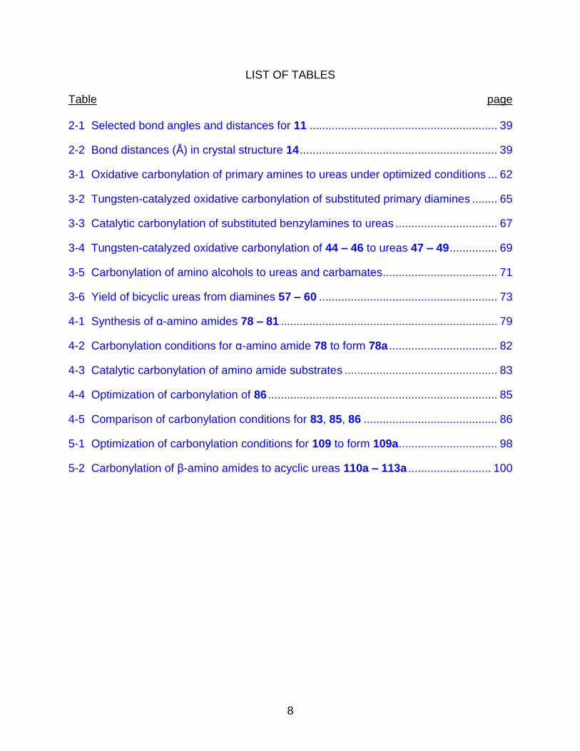
LIST OF TABLES
Table page 2-1 Selected bond angles and distances for 11 ........................................................... 39
2-2 Bond distances (Å) in crystal structure 14 .............................................................. 39
3-1 Oxidative carbonylation of primary amines to ureas under optimized conditions ... 62
3-2 Tungsten-catalyzed oxidative carbonylation of substituted primary diamines ........ 65
3-3 Catalytic carbonylation of substituted benzylamines to ureas ................................ 67
3-4 Tungsten-catalyzed oxidative carbonylation of 44 – 46 to ureas 47 – 49 ............... 69
3-5 Carbonylation of amino alcohols to ureas and carbamates .................................... 71
3-6 Yield of bicyclic ureas from diamines 57 – 60 ........................................................ 73
4-1 Synthesis of α-amino amides 78 – 81 .................................................................... 79
4-2 Carbonylation conditions for α-amino amide 78 to form 78a .................................. 82
4-3 Catalytic carbonylation of amino amide substrates ................................................ 83
4-4 Optimization of carbonylation of 86 ........................................................................ 85
4-5 Comparison of carbonylation conditions for 83, 85, 86 .......................................... 86
5-1 Optimization of carbonylation conditions for 109 to form 109a ............................... 98
5-2 Carbonylation of β-amino amides to acyclic ureas 110a – 113a .......................... 100
9
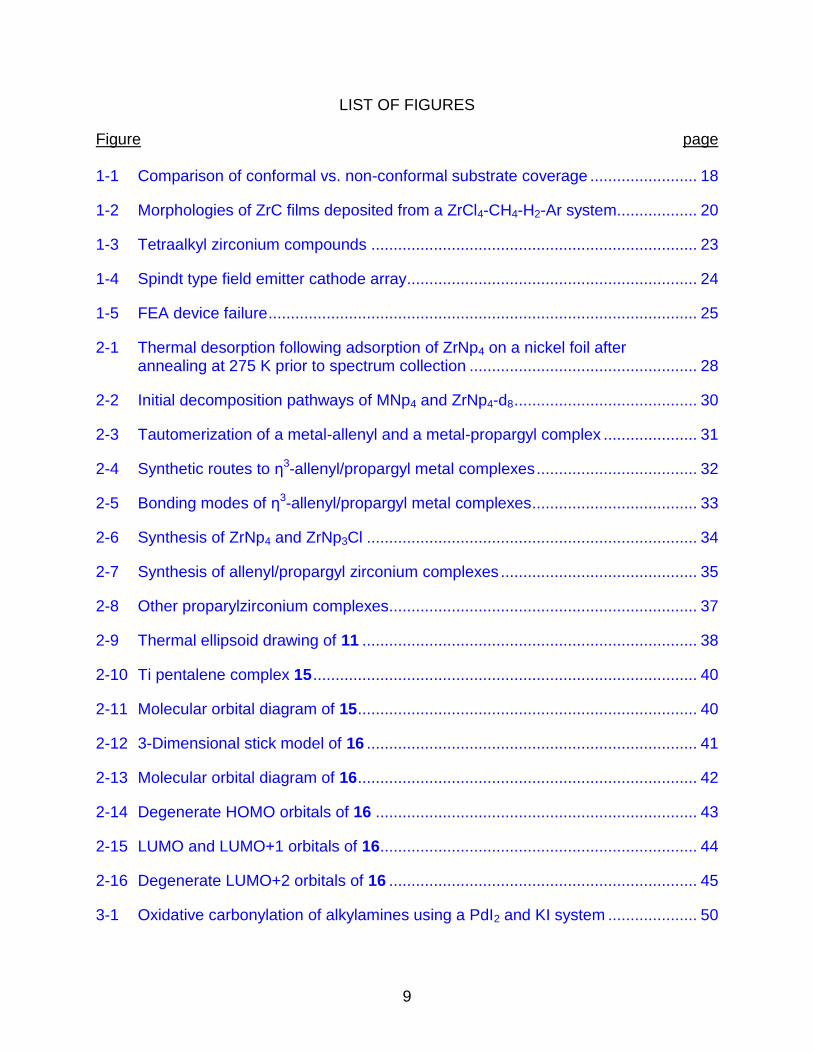
LIST OF FIGURES
Figure page 1-1 Comparison of conformal vs. non-conformal substrate coverage ........................ 18
1-2 Morphologies of ZrC films deposited from a ZrCl4-CH4-H2-Ar system.................. 20
1-3 Tetraalkyl zirconium compounds ......................................................................... 23
1-4 Spindt type field emitter cathode array................................................................. 24
1-5 FEA device failure ................................................................................................ 25
2-1 Thermal desorption following adsorption of ZrNp4 on a nickel foil after annealing at 275 K prior to spectrum collection ................................................... 28
2-2 Initial decomposition pathways of MNp4 and ZrNp4-d8 ......................................... 30
2-3 Tautomerization of a metal-allenyl and a metal-propargyl complex ..................... 31
2-4 Synthetic routes to η3-allenyl/propargyl metal complexes .................................... 32
2-5 Bonding modes of η3-allenyl/propargyl metal complexes ..................................... 33
2-6 Synthesis of ZrNp4 and ZrNp3Cl .......................................................................... 34
2-7 Synthesis of allenyl/propargyl zirconium complexes ............................................ 35
2-8 Other proparylzirconium complexes..................................................................... 37
2-9 Thermal ellipsoid drawing of 11 ........................................................................... 38
2-10 Ti pentalene complex 15 ...................................................................................... 40
2-11 Molecular orbital diagram of 15 ............................................................................ 40
2-12 3-Dimensional stick model of 16 .......................................................................... 41
2-13 Molecular orbital diagram of 16 ............................................................................ 42
2-14 Degenerate HOMO orbitals of 16 ........................................................................ 43
2-15 LUMO and LUMO+1 orbitals of 16 ....................................................................... 44
2-16 Degenerate LUMO+2 orbitals of 16 ..................................................................... 45
3-1 Oxidative carbonylation of alkylamines using a PdI2 and KI system .................... 50
10
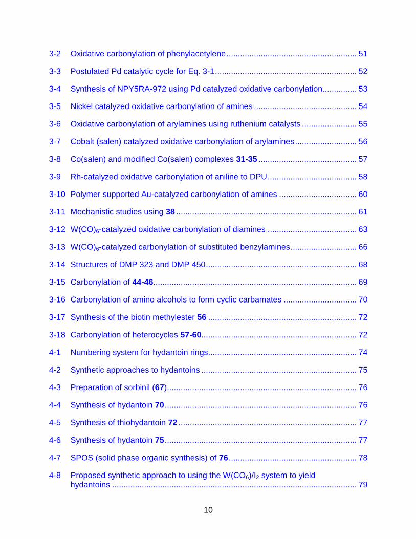
3-2 Oxidative carbonylation of phenylacetylene ......................................................... 51
3-3 Postulated Pd catalytic cycle for Eq. 3-1 .............................................................. 52
3-4 Synthesis of NPY5RA-972 using Pd catalyzed oxidative carbonylation............... 53
3-5 Nickel catalyzed oxidative carbonylation of amines ............................................. 54
3-6 Oxidative carbonylation of arylamines using ruthenium catalysts ........................ 55
3-7 Cobalt (salen) catalyzed oxidative carbonylation of arylamines ........................... 56
3-8 Co(salen) and modified Co(salen) complexes 31-35 ........................................... 57
3-9 Rh-catalyzed oxidative carbonylation of aniline to DPU ....................................... 58
3-10 Polymer supported Au-catalyzed carbonylation of amines .................................. 60
3-11 Mechanistic studies using 38 ............................................................................... 61
3-12 W(CO)6-catalyzed oxidative carbonylation of diamines ....................................... 63
3-13 W(CO)6-catalyzed carbonylation of substituted benzylamines ............................. 66
3-14 Structures of DMP 323 and DMP 450 .................................................................. 68
3-15 Carbonylation of 44-46 ......................................................................................... 69
3-16 Carbonylation of amino alcohols to form cyclic carbamates ................................ 70
3-17 Synthesis of the biotin methylester 56 ................................................................. 72
3-18 Carbonylation of heterocycles 57-60.................................................................... 72
4-1 Numbering system for hydantoin rings ................................................................. 74
4-2 Synthetic approaches to hydantoins .................................................................... 75
4-3 Preparation of sorbinil (67) ................................................................................... 76
4-4 Synthesis of hydantoin 70 .................................................................................... 76
4-5 Synthesis of thiohydantoin 72 .............................................................................. 77
4-6 Synthesis of hydantoin 75 .................................................................................... 77
4-7 SPOS (solid phase organic synthesis) of 76 ........................................................ 78
4-8 Proposed synthetic approach to using the W(CO6)/I2 system to yield hydantoins ........................................................................................................... 79

11
4-9 Synthesis of α-amino amides 78-81 ..................................................................... 79
4-10 Synthesis of 82 from serine methyl ester ............................................................. 80
4-11 MAC synthesis of 82 ............................................................................................ 80
4-12 MAC synthesis of 80 and 81 ................................................................................ 80
4-13 Synthesis of 83 .................................................................................................... 81
4-14 Synthetic scheme for 84-86 ................................................................................. 81
4-15 W(CO)6-catalyzed carbonylation of 78 to hydantoin 78a ..................................... 82
4-16 General carbonylation of amino amide substrates ............................................... 83
5-1 5,6-Dihydrouracil .................................................................................................. 88
5-2 Synthesis of 5,6-dihydrouracils using α,β-unsaturated carboxylic acids .............. 89
5-3 Synthesis of 5,6-dihydrouracils using isobutyric anhydride .................................. 89
5-4 Proposed mechanism of 5,6-dihydrouracil formation ........................................... 90
5-5 Conversion of diamides to 5,6-dihydrouracils by reaction with Pb(OAc)4 ............ 91
5-6 Hydrogenation of uracil to 5,6-dihydrouracil ......................................................... 91
5-7 L-selectride reduction of uracils to form 5,6-dihydrouracils .................................. 92
5-8 Synthesis of dihydrouracils from β-amino acid derivatives ................................... 93
5-9 SPOC synthesis of 5,6-dihydrouracils .................................................................. 93
5-10 N-Boc protection of amino acids to generate 100-103 ......................................... 95
5-11 MAC reaction to yield 104-108 ............................................................................. 96
5-12 Deprotection of N-Boc amino amides to afford 109-113 ...................................... 97
5-13 W(CO)6-catalyzed carbonylation of 109 ............................................................... 98
5-14 Carbonylation of substrates 110-113 to form 110a – 113a using optimized conditions from 109a ............................................................................................ 99
12
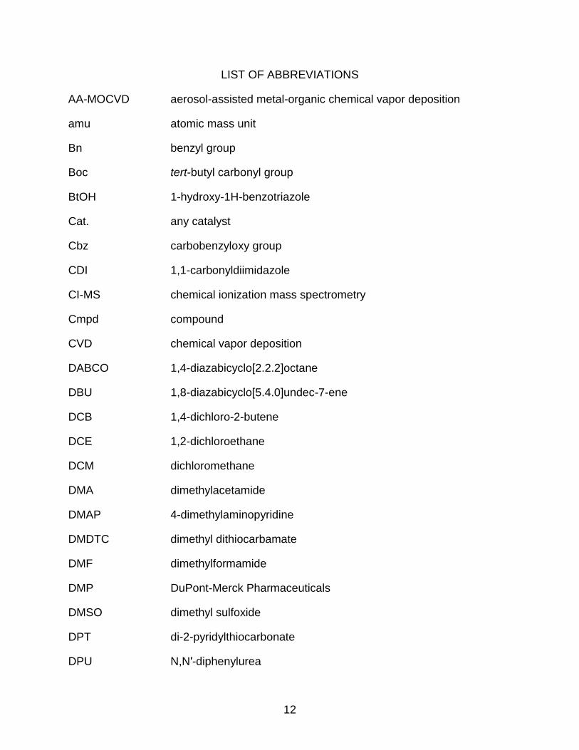
LIST OF ABBREVIATIONS
AA-MOCVD aerosol-assisted metal-organic chemical vapor deposition
amu atomic mass unit
Bn benzyl group
Boc tert-butyl carbonyl group
BtOH 1-hydroxy-1H-benzotriazole
Cat. any catalyst
Cbz carbobenzyloxy group
CDI 1,1-carbonyldiimidazole
CI-MS chemical ionization mass spectrometry
Cmpd compound
CVD chemical vapor deposition
DABCO 1,4-diazabicyclo[2.2.2]octane
DBU 1,8-diazabicyclo[5.4.0]undec-7-ene
DCB 1,4-dichloro-2-butene
DCE 1,2-dichloroethane
DCM dichloromethane
DMA dimethylacetamide
DMAP 4-dimethylaminopyridine
DMDTC dimethyl dithiocarbamate
DMF dimethylformamide
DMP DuPont-Merck Pharmaceuticals
DMSO dimethyl sulfoxide
DPT di-2-pyridylthiocarbonate
DPU N,N′-diphenylurea
13
Ea activation energy
EDCI 1-ethyl-3-(3-dimethylaminopropyl)carbodiimide
EI-MS electrical ionization mass spectrometry
Equiv. equivalent
Et ethyl group
EtOAc ethyl acetate
EtOH ethanol
eV electron volt
FEA field emission array
FT-IR Fourier transform infrared spectroscopy
GLC gas-liquid chromatography
h hour
HIV Human Immunodeficiency Virus
HOMO highest occupied molecular orbital
HPLC high pressure liquid chromatography
iPr isopropyl group
L any ligand
LCMS liquid chromatography mass spectrometry
LMCT ligand-to-metal charge transfer
LUMO lowest unoccupied molecular orbital
M any metal
MAC mixed anhydride coupling
Me methyl group
MEM methoxyethoxymethyl ether
MeOH methanol

14
MO molecular orbital
MOCVD metal-organic chemical vapor deposition
MS mass spectrometry
NMM N-methymorpholine
NMP N-methylpyrrolidinone
NMR nuclear magnetic resonance spectroscopy
Np neopentyl group
PG protecting group
PVD physical vapor deposition
Py. pyridine
rt room temperature
SEM [β-(trimethylsilyl)ethoxy] methyl acetal
SPOC solid phase organic chemistry
SPOS solid phase organic synthesis
TFA trifluoroacetic acid
THF tetrahydrofuran
TLC thin layer chromatography
TMAH tetramethylammonium hydroxide
UHV ultra high vacuum
X any halide

15
Abstract of Dissertation Presented to the Graduate School of the University of Florida in Partial Fulfillment of the Requirements for the Degree of Doctor of Philosophy
SYNTHESIS AND CHARACTERIZATION OF ALKYLZIRCONIUM COMPLEXES FOR THE FABRICATION OF LOW WORK FUNCTION MATERIALS AND SYNTHESIS OF
HYDANTOINS AND DIHYDROURACILS FROM AMINO AMIDES
By
Seth Michael Dumbris
May 2010
Chair: Lisa McElwee-White Major: Chemistry
Alkylzirconium compounds have been studied as precursors for the chemical
vapor deposition of ZrC for application as low work function materials in devices such as
field emitter arrays. Tetraneopentylzirconium and trineopentylzirconium monochloride
were synthesized to test the decomposition pathways using mass spectrometry to help
further understand the thermal decomposition under deposition conditions. The initial
decomposition step of tetraneopentylzirconium was determined to occur through a
mixture of α- and γ-hydride elimination processes resulting in a complex mass
spectrum.
The homoleptic alkylzirconium complex tetra-η3(phenylpropargyl)zirconium was
synthesized. It exhibited interesting bonding resulting in a D2d symmetric, 16 electron
complex that was characterized with X-ray crystallography. The bonding was further
analyzed by computational analysis, which determined the HOMO-LUMO gap to be 5.2
eV and showed the highly delocalized bonding of the phenylpropargyl ligands to the
zirconium center.
16
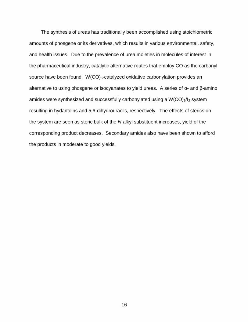
The synthesis of ureas has traditionally been accomplished using stoichiometric
amounts of phosgene or its derivatives, which results in various environmental, safety,
and health issues. Due to the prevalence of urea moieties in molecules of interest in
the pharmaceutical industry, catalytic alternative routes that employ CO as the carbonyl
source have been found. W(CO)6-catalyzed oxidative carbonylation provides an
alternative to using phosgene or isocyanates to yield ureas. A series of α- and β-amino
amides were synthesized and successfully carbonylated using a W(CO)6/I2 system
resulting in hydantoins and 5,6-dihydrouracils, respectively. The effects of sterics on
the system are seen as steric bulk of the N-alkyl substituent increases, yield of the
corresponding product decreases. Secondary amides also have been shown to afford
the products in moderate to good yields.
17
CHAPTER 1 THIN FILM DEPOSITON OF ZrC FOR THE FABRICATION OF LOW WORK
FUNCTION MATERIALS
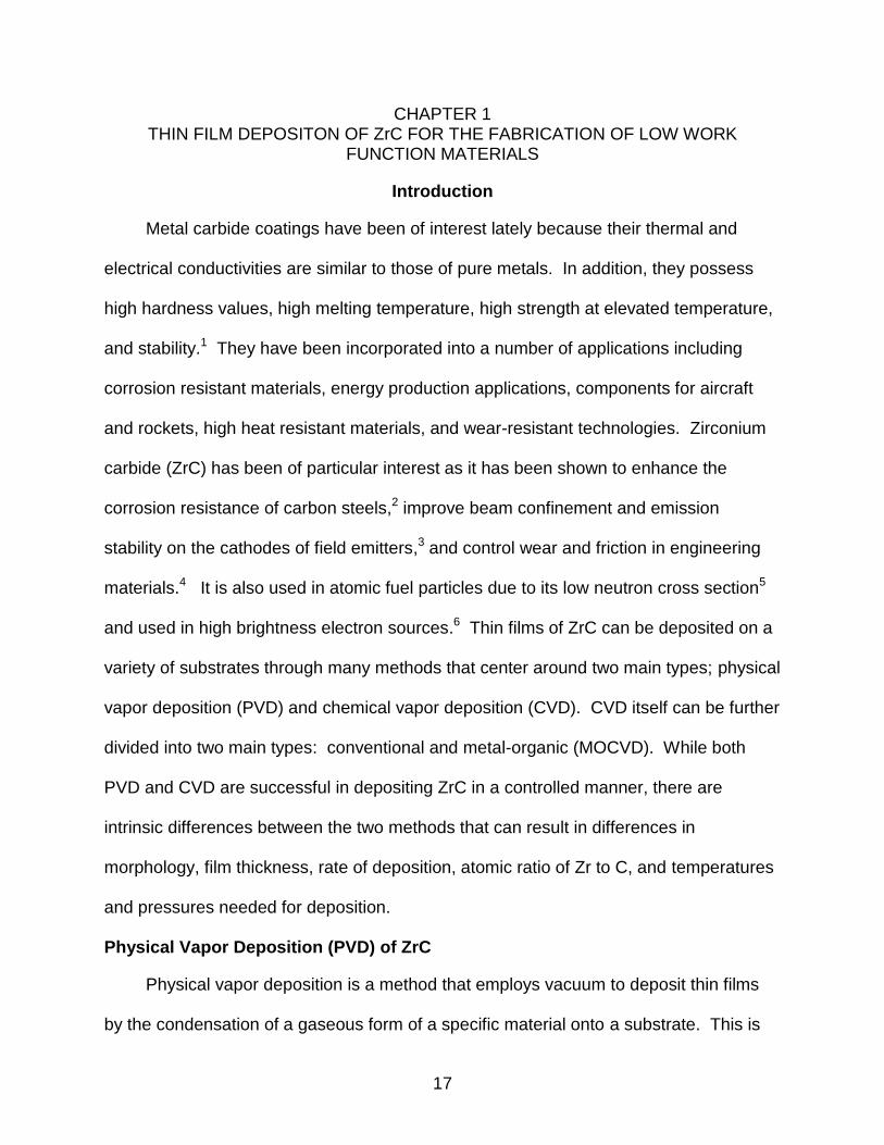
Introduction
Metal carbide coatings have been of interest lately because their thermal and
electrical conductivities are similar to those of pure metals. In addition, they possess
high hardness values, high melting temperature, high strength at elevated temperature,
and stability.1 They have been incorporated into a number of applications including
corrosion resistant materials, energy production applications, components for aircraft
and rockets, high heat resistant materials, and wear-resistant technologies. Zirconium
carbide (ZrC) has been of particular interest as it has been shown to enhance the
corrosion resistance of carbon steels,2 improve beam confinement and emission
stability on the cathodes of field emitters,3 and control wear and friction in engineering
materials.4 It is also used in atomic fuel particles due to its low neutron cross section5
and used in high brightness electron sources.6 Thin films of ZrC can be deposited on a
variety of substrates through many methods that center around two main types; physical
vapor deposition (PVD) and chemical vapor deposition (CVD). CVD itself can be further
divided into two main types: conventional and metal-organic (MOCVD). While both
PVD and CVD are successful in depositing ZrC in a controlled manner, there are
intrinsic differences between the two methods that can result in differences in
morphology, film thickness, rate of deposition, atomic ratio of Zr to C, and temperatures
and pressures needed for deposition.
Physical Vapor Deposition (PVD) of ZrC
Physical vapor deposition is a method that employs vacuum to deposit thin films
by the condensation of a gaseous form of a specific material onto a substrate. This is

18
conducted in a directional, line-of-sight manner through numerous methods, one of
which is evaporative deposition. In this method, the material to be deposited is heated
under vacuum on one side of the reactor and is distributed on the substrate opposite it.
This can be assisted by an inert carrier gas to help transfer or not. The substrate is
then coated on any surface that is exposed to the flow of gas/deposited material. Other
PVD methods that have been successfully employed for the deposition of ZrC include e-
beam bombardment,6 pulsed laser ablation,7 laser cladding,8 and magnetron
sputtering.9 These methods have proven successful at depositing ZrC onto many
substrates including steel, silica, molybdenum, tungsten, and graphite.
Figure 1-1. Comparison of conformal vs. non-conformal substrate coverage. Left) Conformal coverage of film on substrate. Right) Non-conformal coverage of film on substrate.
These methods also tend to be fairly mild to the substrate as the temperature
needed often does not exceed 300 °C. This is not always the case, however, as laser
cladding superficially melts the surface of the substrate.8 While this generally does not
affect the mechanical properties of the material, it could potentially affect the substrate if
it has more than one layer. In addition as this is a line-of-sight deposition method at low
pressure, a substrate that is not smooth will not have conformal coverage. Areas have
thicker coverage on the direction facing the gas/deposited material flow while the face

19
opposite would receive less. Achieving conformal coverage on an inset substrate area
would also not be viable (Figure 1-1).
Conventional Chemical Vapor Deposition (CVD) of ZrC
Conventional CVD uses binary metal halide precursors, such as ZrCl4, and
methane (CH4) as the carbon source under a reducing H2 atmosphere to achieve
deposition of ZrC. The metal source, ZrCl4, is heated under reduced pressure and is
transported to the substrate, which is heated to 1000-2000 °C. The zirconium halide
and CH4 react to generate ZrC on the surface. As the reaction does not occur until the
reactants reach the substrate, conformal coverage is much easier to obtain. Control
parameters such as temperature, pressure, carbon source, and flux of gas precursors
have been thoroughly examined.10-12 An in-depth thermodynamic analysis predicted
that, at equilibrium, it would be easy to manipulate the exact molecular composition of
the solid deposited by controlling the input partial-pressure of CH4 with a constant ZrCl4
feed.13 These pressure ranges at 1900 K are 5x10⁻³ torr < P°CH4<10-2 torr and 10-2 torr
<P°ZrCl4<10-1 torr, where P°CH4+ P°ZrCl4+ P°H2 = 1. Experimentally, obtaining the desired
1:1 stoichiometry of Zr to C has been achieved.12
A kinetic analysis of the deposition mechanism was sought to better help
understand and control the ZrC deposition process.14 It was found that at temperatures
below 1523 K the activation energy (Ea) for deposition was 85 kJ/mol and at
temperatures above 1523 K, Ea = 305 kJ/mol. This indicated a mechanistic change
above that temperature, consistent with a surface kinetic driven process, which is
strongly dependant on deposition temperature.15 Previously, it was also determined
that Zr and C appear to be deposited separately during the process and not
simultaneously in this type of system.16 This was significant because this ZrCl4-CH4-H2

20
system’s surface reaction kinetics should be dominated by deposition of Zr or C, or the
reaction of the two to form carbide. Independently, the decomposition Ea of CH4 was
found to range from 280-380 kJ/mol in an experiment involving the deposition of
pyrocarbon using CH4 as the carbon source under similar experimental controls as in
the ZrC system.17 In addition, the pyrocarbon studies showed that gaseous
hydrocarbons tend to decompose into a complex mixture of organic molecules in the
form of liquid or plastic-like droplets.
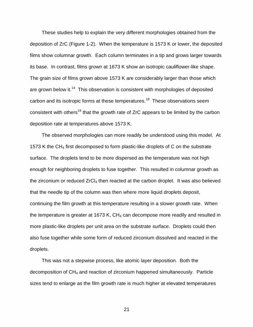
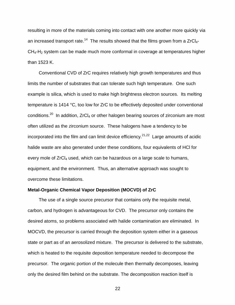
Figure 1-2. Morphologies of ZrC films deposited from a ZrCl4-CH4-H2-Ar system. a) Film grown at 1573 K. b) Film grown at 1673 K.14
21
These studies help to explain the very different morphologies obtained from the
deposition of ZrC (Figure 1-2). When the temperature is 1573 K or lower, the deposited
films show columnar growth. Each column terminates in a tip and grows larger towards
its base. In contrast, films grown at 1673 K show an isotropic cauliflower-like shape.
The grain size of films grown above 1573 K are considerably larger than those which
are grown below it.14 This observation is consistent with morphologies of deposited
carbon and its isotropic forms at these temperatures.18 These observations seem
consistent with others19 that the growth rate of ZrC appears to be limited by the carbon
deposition rate at temperatures above 1573 K.
The observed morphologies can more readily be understood using this model. At
1573 K the CH4 first decomposed to form plastic-like droplets of C on the substrate
surface. The droplets tend to be more dispersed as the temperature was not high
enough for neighboring droplets to fuse together. This resulted in columnar growth as
the zirconium or reduced ZrCl4 then reacted at the carbon droplet. It was also believed
that the needle tip of the column was then where more liquid droplets deposit,
continuing the film growth at this temperature resulting in a slower growth rate. When
the temperature is greater at 1673 K, CH4 can decompose more readily and resulted in
more plastic-like droplets per unit area on the substrate surface. Droplets could then
also fuse together while some form of reduced zirconium dissolved and reacted in the
droplets.
This was not a stepwise process, like atomic layer deposition. Both the
decomposition of CH4 and reaction of zirconium happened simultaneously. Particle
sizes tend to enlarge as the film growth rate is much higher at elevated temperatures
22
resulting in more of the materials coming into contact with one another more quickly via
an increased transport rate.14 The results showed that the films grown from a ZrCl4-
CH4-H2 system can be made much more conformal in coverage at temperatures higher
than 1523 K.
Conventional CVD of ZrC requires relatively high growth temperatures and thus
limits the number of substrates that can tolerate such high temperature. One such
example is silica, which is used to make high brightness electron sources. Its melting
temperature is 1414 °C, too low for ZrC to be effectively deposited under conventional
conditions.20 In addition, ZrCl4 or other halogen bearing sources of zirconium are most
often utilized as the zirconium source. These halogens have a tendency to be
incorporated into the film and can limit device efficiency.21,22 Large amounts of acidic
halide waste are also generated under these conditions, four equivalents of HCl for
every mole of ZrCl4 used, which can be hazardous on a large scale to humans,
equipment, and the environment. Thus, an alternative approach was sought to
overcome these limitations.
Metal-Organic Chemical Vapor Deposition (MOCVD) of ZrC
The use of a single source precursor that contains only the requisite metal,
carbon, and hydrogen is advantageous for CVD. The precursor only contains the
desired atoms, so problems associated with halide contamination are eliminated. In
MOCVD, the precursor is carried through the deposition system either in a gaseous
state or part as of an aerosolized mixture. The precursor is delivered to the substrate,
which is heated to the requisite deposition temperature needed to decompose the
precursor. The organic portion of the molecule then thermally decomposes, leaving
only the desired film behind on the substrate. The decomposition reaction itself is
23
initiated at the substrate surface, which results in conformal coverage and does not
have line-of-sight issues as in PVD. As with conventional CVD, growth rates are also a
function of a variety of factors including identity of the precursor, deposition
temperature, flow rate and carrier gas, and reactor design.
There are limitations on the metal-organic precursors that can be used for the
deposition of ZrC. Alkyl ligands placed on the zirconium center cannot contain any β-
hydrogen atoms as β-hydride elimination occurs readily at room temperature from early
transition metals. Heteroatoms in the ligands are avoided, as they can be incorporated
into the film. The compound must also be sufficiently stable to be handled.
Tetramethylzirconium, Zr(CH3)4, meets the criteria of no β-hydrogens and no
heteroatoms, however, it cannot be used for deposition of ZrC as it readily decomposes
at -20 °C.23 Tetraallylzirconium is also known and does have β-hydrogens, but does not
have the necessary geometry to eliminate them. It is also unable to be utilized for CVD
as it decomposes readily at temperatures above -20 °C. The most heavily studied
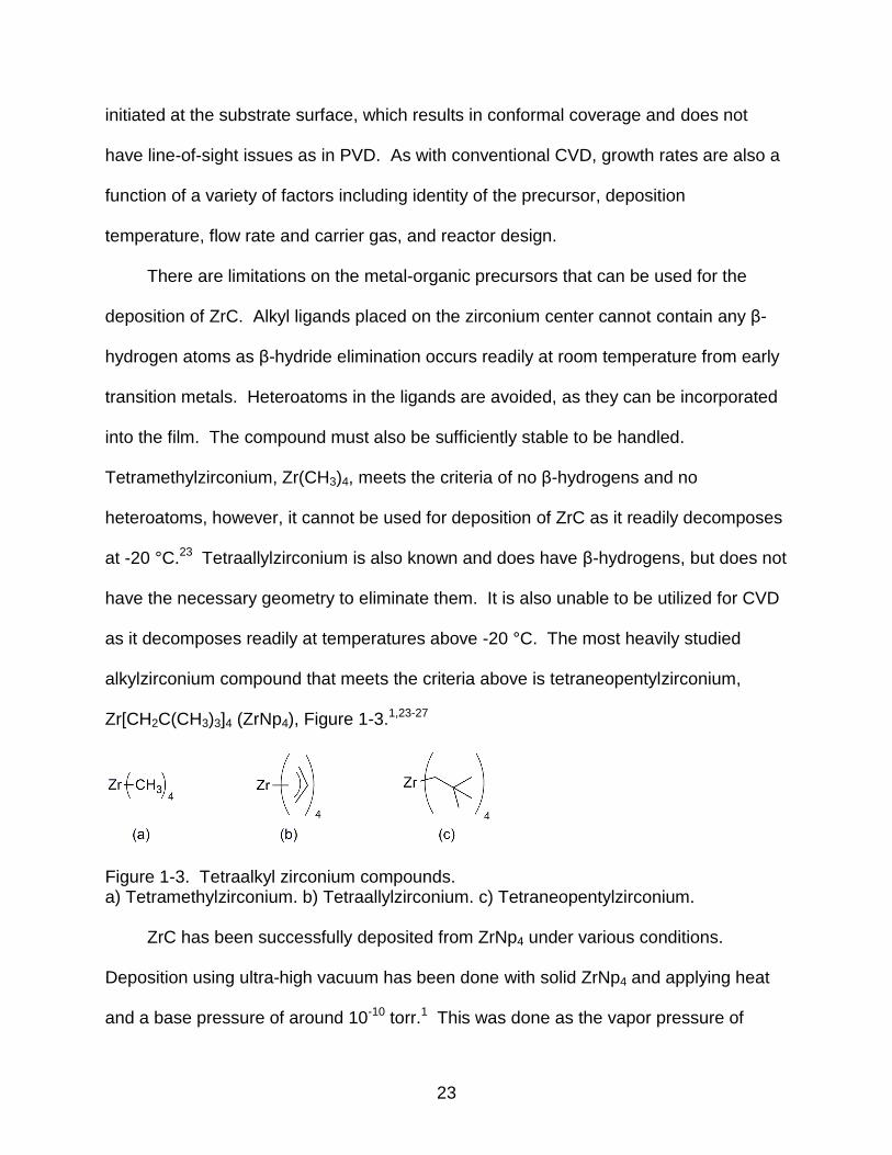
alkylzirconium compound that meets the criteria above is tetraneopentylzirconium,
Zr[CH2C(CH3)3]4 (ZrNp4), Figure 1-3.1,23-27
Figure 1-3. Tetraalkyl zirconium compounds. a) Tetramethylzirconium. b) Tetraallylzirconium. c) Tetraneopentylzirconium.
ZrC has been successfully deposited from ZrNp4 under various conditions.
Deposition using ultra-high vacuum has been done with solid ZrNp4 and applying heat
and a base pressure of around 10-10 torr.1 This was done as the vapor pressure of

24
ZrNp4 itself is very low, which makes it difficult to volatilize. Another route to overcome
low volatility is to dissolve the material in a high-boiling temperature organic solvent.
The solvent can be nebulized and carried to the deposition reactor in a process called
aerosol-assisted metal-organic CVD (AA-MOCVD). The carrier solvent then is removed
under vacuum while traveling through the reactor, delivering an aerosol of ZrNp4 to the
substrate.28
High Brightness Electron Devices
Electron sources based on vacuum tubes have been around for many years, with
the use of thermionic emission technology used for the last 30 years in high brightness
electron sources. The Department of Defense currently operates over 170,000 of these
tubes which are utilized in 272 applications in various fields. Devices such as the SPY-
1 cross-field amplifier system, high speed data communications in submarines, radar,
sonar, and other electronic warfare systems make use of these vacuum tubes. The
devices operate by the electrical generation of heat reaching a threshold temperature at
which the flow of electrons across the system is possible.
Figure 1-4. Spindt type field emitter cathode array.
Due to this parameter, the devices require high power consumption and have a
long system response time in switching from “standby” to “on” modes. While thermionic
emission technology is highly reliable, there exists a strong demand to decrease both

25
the size of the devices and their power consumption. One possible alternative to this
technology is the use of gated field emission arrays (FEAs) (Figure 1-4).29
Gated FEAs provide a good alternative in that they have a near instant on
capability and do not require time to heat prior to use. The units themselves operate
cold and give off little heat of their own, consequently requiring much less heat
dissipation equipment and lowering the overall size of the device. This results in
space/weight savings over devices that employ vacuum tubes. Higher anode current is
also possible from these devices while using less power overall. These reasons result
in substantial savings over currently employed thermionic emission technology.
Figure 1-5. FEA device failure. a) Arcing damage to tips and gate electrode. b) Dulling of emitter tips due to ion bombardment.
The reliability of FEAs needs to be improved before the technology can be of
general use. Some of the problems to be overcome are illustrated in Figure 1-5.29 In
the first the gate film has melted and vaporized, exposing the underlying SiO2 film,
thereby destroying the tips around the area. This cathode destruction can result in a
partial or complete loss of system voltage from the array as a whole. Ion bombardment
is also a problem attributed to ions being formed by electron beam ionization. These
ions are accelerated and impact the field emitter surface, which can dull the emitter tip
or lead to a nanoprotrusion on its surface. A nanoprotrusion is then capable of
26
generating a large local emission field, which if intense enough, can cause a vacuum
arc to occur and damage the cathode.
Reliability of devices can be improved by lowering the operational voltage of the
system, as this reduces the likelihood of the previously mentioned problems from
occurring. This is done by either fabricating cathodes out of, or by coating conventional
electrodes with a thin film of a low work function material. Certain carbides, borides,
nitrides, and carbon based thin films have low work functions ranging from 2-3.5 eV.30
When these materials are incorporated into a high brightness electron source, emission
currents can be increased by a factor of 100, as shown in the use of conventional Si
and Mo systems. This operational system was successfully able to have its work
function lowered from 4 eV to 3 eV, resulting in an overall current density increase from
the system.30
Of these low work function materials, ZrC is a promising candidate. Its bulk work
function is between 2.0-2.2 eV and it has been demonstrated to lower the system’s
operational work function from 4.85 eV to 3.15 eV on a Si(100) tip array resulting in a
voltage reduction of about 23% while maintaining the same current.6 When a Mo(100)
tip array was coated with ZrC, its work function was lowered from 4.60 eV to 3.58 eV,
resulting in a voltage reduction of 44% while maintaining the same current. In addition
to the power savings, ZrC is also much more durable than many substrates, like Si.
The melting point of ZrC is more than twice that of Si.20 Its durability and wear
resistance are profound with hardness values as high as 30.2-35.6 GPa.7,9 Lastly, the
resistivity of ZrC is around 10-4 lower than that of Si making it a very good candidate for
incorporation into high brightness electron sources.20

27
CHAPTER 2 SYNTHESIS, CHARACTERIZATION, AND COMPUTATIONAL ANALYSIS OF
ALKYLZIRCONIUM COMPLEXES
Background
One of the most studied complexes for the MOCVD of ZrC is ZrNp4. The molecule
contains no β-hydrogens, is stable at temperatures reasonable for deposition, is
reasonably volatile, and contains no heteroatoms which might contaminate the
deposited film. It is a homoleptic compound, containing only one type of ligand, the
neopentyl group. The inclusion of only one type of ligand makes its decomposition
study easier as fragmentation has limited options. Due to this, its stability, and relative
ease of synthesis, it has been the focus of decomposition studies conducted with the
hope that knowledge of the decomposition mechanism can give insight into the MOCVD
process. This may also lead to development of a new type of alkylzirconium compound
as decomposition may lead to better understanding of ligand design. A particular issue
that has been of interest is how the final film Zr/C ratio is not 1:1 as expected; rather
ratios of 1:2 to 1:5 have been reported.1,26-28,31
Mechanistic Analysis of ZrNp4 Decomposition
Early studies indicated that at a deposition temperature of 500 °C, ZrC could be
deposited in stable crystalline thin films as confirmed by XRD and XPS data. However,
AES data indicated that the Zr/C ratio was 1:2, despite efforts to lower it by controlling
deposition parameters.25 To help better understand this observed result, ZrC was
deposited on Ni substrates and further studies conducted. The surface of these
samples was then exposed to a set amount of ZrNp4 below 125 K, to prevent premature
ZrNp4 decomposition. The films were then annealed at 275 K to remove the ZrNp4
multilayers, achieving monolayer coverage.1
28
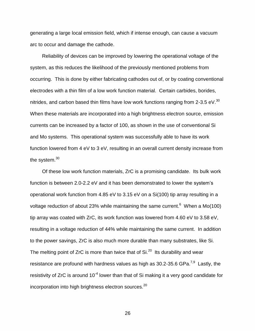
The films were then placed in an ultrahigh vacuum (UHV) chamber and heated to
higher temperatures while monitoring the effluent gas by MS. Around 410 K a
simultaneous mass loss of 29, 41, and 57 amu was observed with mass loss of 15 and
16 amu occurring near 500 K (Figure 2-1) as measured by mass spectrometry.1
Figure 2-1. Thermal desorption following adsorption of ZrNp4 on a nickel foil after annealing at 275 K prior to spectrum collection.1
As the films have already undergone desorption, this can only be attributed to
hydrocarbon cracking in the mass spectrometer, most likely from a single desorbing
hydrocarbon. No direct peak of m/z 56, corresponding to isobutylene, could be
observed, making β-methyl elimination unlikely. Also, no Zr containing fragments were
detectable. This makes the loss of fragments m/z 29, 41, and 57 likely to have come
mostly from the loss of neopentane itself. This was very likely as surface IR confirmed
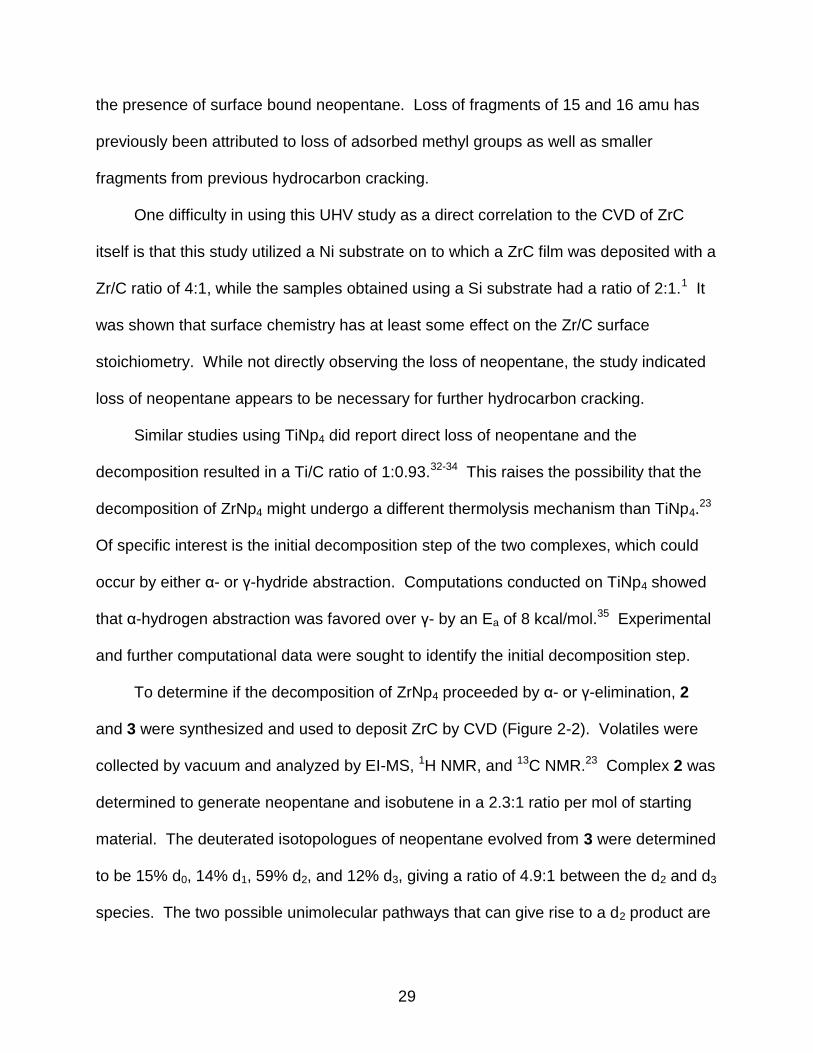
29
the presence of surface bound neopentane. Loss of fragments of 15 and 16 amu has
previously been attributed to loss of adsorbed methyl groups as well as smaller
fragments from previous hydrocarbon cracking.
One difficulty in using this UHV study as a direct correlation to the CVD of ZrC
itself is that this study utilized a Ni substrate on to which a ZrC film was deposited with a
Zr/C ratio of 4:1, while the samples obtained using a Si substrate had a ratio of 2:1.1 It
was shown that surface chemistry has at least some effect on the Zr/C surface
stoichiometry. While not directly observing the loss of neopentane, the study indicated
loss of neopentane appears to be necessary for further hydrocarbon cracking.
Similar studies using TiNp4 did report direct loss of neopentane and the
decomposition resulted in a Ti/C ratio of 1:0.93.32-34 This raises the possibility that the
decomposition of ZrNp4 might undergo a different thermolysis mechanism than TiNp4.23
Of specific interest is the initial decomposition step of the two complexes, which could
occur by either α- or γ-hydride abstraction. Computations conducted on TiNp4 showed
that α-hydrogen abstraction was favored over γ- by an Ea of 8 kcal/mol.35 Experimental
and further computational data were sought to identify the initial decomposition step.
To determine if the decomposition of ZrNp4 proceeded by α- or γ-elimination, 2
and 3 were synthesized and used to deposit ZrC by CVD (Figure 2-2). Volatiles were
collected by vacuum and analyzed by EI-MS, 1H NMR, and 13C NMR.23 Complex 2 was
determined to generate neopentane and isobutene in a 2.3:1 ratio per mol of starting
material. The deuterated isotopologues of neopentane evolved from 3 were determined
to be 15% d0, 14% d1, 59% d2, and 12% d3, giving a ratio of 4.9:1 between the d2 and d3
species. The two possible unimolecular pathways that can give rise to a d2 product are

30
γ-hydride elimination or a radical process generating Np3Zr· and Np·. However, there
was no evidence for Np-Np formation in the CVD of 3. This does not rule out the
possibility of radical formation, but simply makes it a less likely candidate.
Computations showed that the Zr-C bond length is 0.15 Å longer than that of a Ti-C
bond in MNp4, where M is Zr and Ti respectively. The shorter bond length was
expected when comparing a first row metal complex to a second row. In addition, it was
determined that γ-hydrogen abstraction was 5.2 kcal/mol lower in activation energy than
α-hydrogen abstraction computationally.23
Figure 2-2. Initial decomposition pathways of MNp4 and ZrNp4-d8.

31
The large amount of Np-d2 present after deposition, absence of a Np-Np dimer,
and computational evidence suggested that γ-hydrogen abstraction is the predominant
pathway for initial decomposition of ZrNp4. Lastly, overall 70.4% to 29.6% molar
amounts of neopentane and isobutene were found for the decomposition of 2 and that
the ratio holds within experimental error for 3, suggesting that the two compounds
undergo similar decomposition pathways.23
Both major studies on the deposition decomposition pathway have focused on
following the deposition of ZrC from ZrNp4 by experimentally examining the gases after
deposition has occurred and with computational analysis reinforcing experimental
results.
Propargyl/Allenyl Zirconium Complexes
The design and use of other alkylzirconium complexes that can potentially be used
for MOCVD of ZrC has also been of interest. The inability to have ligands with a β-
hydrogen or the presence of heteroatoms severely limits the functionality that can be
incorporated into these molecules. One ligand group that had not received much
examination is that of a propargyl group. Propargyl groups cannot undergo β-hydride
elimination as they are completely unsaturated in the β-position. They also have unique
structural and bonding characteristics that makes their potential usage chemically
interesting.36 A tautomerization exists between the allenyl and propargyl forms allowing
for different modes of bonding to metals (Figure 2-3).36
Figure 2-3. Tautomerization of a metal-allenyl and a metal-propargyl complex.
32
The ligands are capable of donating four electrons to the metal system through
various σ and π interactions. Standard enthalpy of formation values of 42.2 kcal/mol for
MeC≡CH and 45.5 kcal/mol for H2C=C=CH2 show that the free propargyl species is
slightly more stable than the allenyl,37 but studies have shown that the M-allenyl bonds
are stronger than the corresponding propargyl-metal interaction. In general, the allenyl
tautomer is favored when placed on a metal system.38 Several synthetic strategies
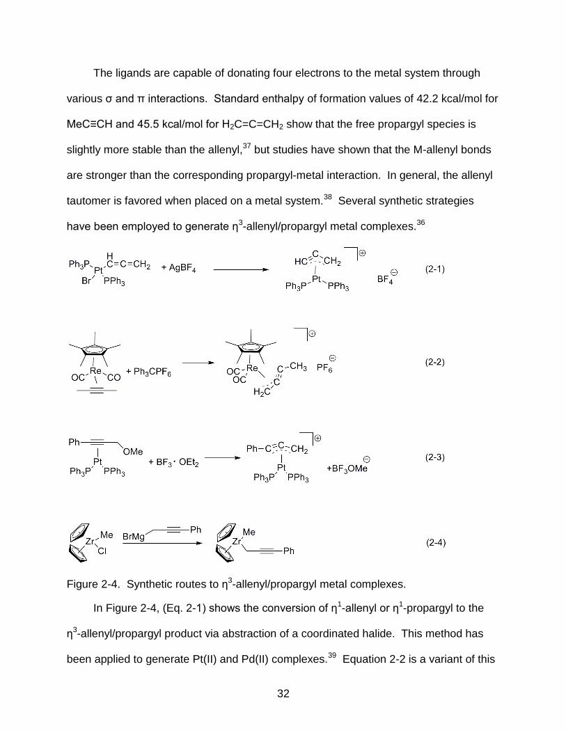
have been employed to generate η3-allenyl/propargyl metal complexes.36
Figure 2-4. Synthetic routes to η3-allenyl/propargyl metal complexes.
In Figure 2-4, (Eq. 2-1) shows the conversion of η1-allenyl or η1-propargyl to the
η3-allenyl/propargyl product via abstraction of a coordinated halide. This method has
been applied to generate Pt(II) and Pd(II) complexes.39 Equation 2-2 is a variant of this
33
by abstraction of a hydride from a coordinated η2-acetylene ligand.40 Another technique
is to treat an η2-propargyl alcohol or ether complex with a Lewis acid (Eq. 2-3).39 Lastly,
equation 2-4 shows how reactions of early transition metal halide complexes with
Grignard or related reagents have proven useful to generate η3-allenyl/propargyl
complexes.
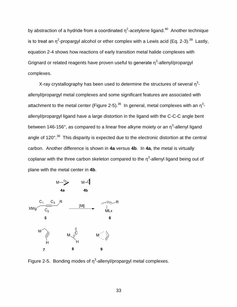
X-ray crystallography has been used to determine the structures of several η3-
allenyl/propargyl metal complexes and some significant features are associated with
attachment to the metal center (Figure 2-5).36 In general, metal complexes with an η3-
allenyl/propargyl ligand have a large distortion in the ligand with the C-C-C angle bent
between 146-156°, as compared to a linear free alkyne moiety or an η3-allenyl ligand
angle of 120°.36 This disparity is expected due to the electronic distortion at the central
carbon. Another difference is shown in 4a versus 4b. In 4a, the metal is virtually
coplanar with the three carbon skeleton compared to the η3-allenyl ligand being out of
plane with the metal center in 4b.
Figure 2-5. Bonding modes of η3-allenyl/propargyl metal complexes.

34
The C1-C2 and C2-C3 bond lengths in ligands of the type in 6 are between 1.34-
1.40 Å and 1.22-1.28 Å, respectively, different than that of the free alkyne in 5, which
has distances of 1.47 Å and 1.20 Å,41 respectively. Complexes 7, 8, 9 illustrate the
three possible η1- and η3-bondings of the allenyl/propargyl ligand itself. The bond
lengths mentioned for 6 reduce the canonical structures to primarily those depicted in 7
and 9.36
Synthesis of Alkylzirconium Complexes
The synthesis of alkyl substituted zirconium complexes was achieved using ZrCl4
and the requisite Grignard or lithium reagents, resulting in a series of alkyl-halogen
transmetalation reactions. Controlling stoichiometry of the alkylating reagent allows for
the synthesis of mono through tetra-substituted complexes, depending on the desired
molecule. The syntheses of the alkyl zirconium complexes utilized are outlined in
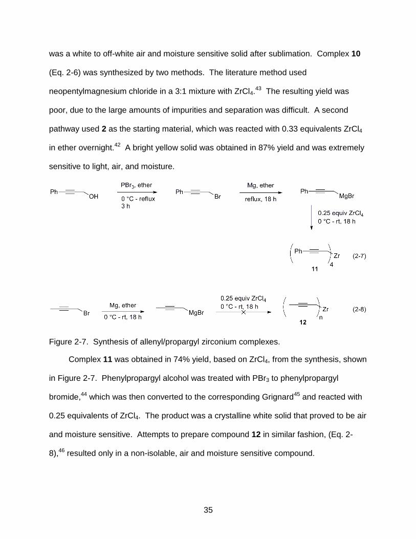
Figure 2-642,43 and Figure 2-7.44-46
Figure 2-6. Synthesis of ZrNp4 and ZrNp3Cl.
Synthesis of 2 (Eq. 2-5) was achieved by literature procedures starting with the
conversion of neopentyl chloride to the corresponding Grignard, which was then reacted
with 0.25 equivalents of ZrCl4 to afford the product in 70% yield.42 The purified product
35
was a white to off-white air and moisture sensitive solid after sublimation. Complex 10
(Eq. 2-6) was synthesized by two methods. The literature method used
neopentylmagnesium chloride in a 3:1 mixture with ZrCl4.43 The resulting yield was
poor, due to the large amounts of impurities and separation was difficult. A second
pathway used 2 as the starting material, which was reacted with 0.33 equivalents ZrCl4
in ether overnight.42 A bright yellow solid was obtained in 87% yield and was extremely
sensitive to light, air, and moisture.
Figure 2-7. Synthesis of allenyl/propargyl zirconium complexes.
Complex 11 was obtained in 74% yield, based on ZrCl4, from the synthesis, shown
in Figure 2-7. Phenylpropargyl alcohol was treated with PBr3 to phenylpropargyl
bromide,44 which was then converted to the corresponding Grignard45 and reacted with
0.25 equivalents of ZrCl4. The product was a crystalline white solid that proved to be air
and moisture sensitive. Attempts to prepare compound 12 in similar fashion, (Eq. 2-
8),46 resulted only in a non-isolable, air and moisture sensitive compound.
36
Results and Discussion
Tetraneopentylzirconium (ZrNp4) Studies
In order to generate alkylzirconium precursors that can successfully deposit ZrC
by MOCVD, it is helpful to understand how the precursor decomposes under deposition
conditions. The insight provided by the isotopologue analysis from Xue23 is very helpful
in examining the decomposition of 2 and 3 experimentally and comparing it with
computational data. It suggested that the initial decomposition step of 2 was γ-
hydrogen abstraction. However, the method employed collected and analyzed gasses
from the entire deposition experiment, not just the initial decomposition. Another way to
analyze these compounds is the use of mass spectrometry.47-49 CVD is a thermal
process whereas mass spectrometry is ionic, and care must be taken to not rely too
heavily upon such data to predict CVD behavior, as smaller fragments are not
necessarily derived from larger ones. Mass spectrometry can however provide good
insight into the relative fragmentation patterns of various single-source organometallic
precursors.48,49
A CI-MS of 2 was obtained and the spectrum indicated a complex mixture of
peaks that could not be assigned to appropriate decomposition pathways. In addition,
oxidized Zr-alkyl peaks were also visible in the spectrum preventing accurate
assignment. Compound 10 was synthesized with the hope that a similar MS analysis
could be conducted on the compound to yield insight into a similar decomposition
pathway. However, 10 proved to be more sensitive than 2 as both light and the
presence of solvents rapidly decomposed the complex, rendering analysis impossible.

37
Characterization of η3- Tetra(η3-phenylpropargyl)zirconium
The characterization of the phenylpropargyl compound 11 has yielded very
interesting results. 1H NMR data consisted of a single aliphatic methylene peak at δ
3.23 ppm. Comparisons can be made between 11 and 13 and 14 (Figure 2-8).39,50
Figure 2-8. Other proparylzirconium complexes.
It was experimentally determined by variable temperature 1H NMR that 13
contained two phenylpropargyl ligands on the zirconocene with one being coordinated
in an η1-fashion while the other exhibited an η3- mode of coordination. The 1H NMR
spectrum of 13 had one signal for the CH2 group at δ 2.80 ppm from 223-303 K. At 180
K, the signal decoalesces into two equal intensity peaks at δ 3.3 and 1.9 ppm, which
were assigned to η3- and η1- coordination, respectively. Confirmation of this was
subsequently obtained with 14 as it only has one resonance at δ 3.37 ppm,
corresponding to an η3-propargyl ligand.
Based on these chemical shifts, it seemed probable that the lone resonance in the
1H NMR spectrum of 11 corresponded to an η3-coordination of the phenylpropargyl
ligand. While the reaction to synthesize 11 was conducted in a 4:1 ratio of Grignard
reagent to ZrCl4, the number of ligands on the zirconium center could theoretically be
from four to six (ZrRn=4-6). Any number n above four would result in an –ate complex,

38
with Mg2+ as the counterion. Also, formation of Zr dimers could have also been
possible.
The structure of 11 was determined by X-ray crystallography to be a tetra(η3-
phenylpropargyl)zirconium complex (Figure 2-9). The structure itself contains high
symmetry, belonging to the D2d point group. All four ligands are bound in an η3- fashion
and are four electron donors, resulting in a 16 electron complex. Bond lengths for
comparison to 14 are provided (Table 2-1, Table 2-2).
Figure 2-9. Thermal ellipsoid drawing of 11. Hydrogen atoms are omitted for clarity.
Complexes 11 and 14 show structural similarities in that the C-C-C bond angles
are 145.38(16)° and 155.4(3)°, respectively. The Zr-C1 bond length in 11 is shorter
than that of 14 (Table 2-2) while the Zr-C2 is about the same in both structures and Zr-
C3 is slightly longer in 14. A point of interest is that all Zr-propargyl bond lengths in 11
are approximately the same length, differing by a net 0.09 Å overall, whereas those in
14 differ by a much larger value, 0.297 Å. This is possibly due to the large structural

39
differences between the two as 11 has an electron count of 16, while 14 has an electron
count of 18 and the phenylpropargyl ligand is sterically encumbered by two
cyclopentadiene rings. This could rationalize the shorter bond length along Zr-C1 in 11
as the metal must rely more on the σ-donation to gain electron density as it does not
have the cyclopentadienyl π-system to draw upon.
Table 2-1. Selected bond angles and distances for 11
Bond Angle (°)
C2-C1-Zr 70.08(9)
C3-C2-C1 154.38(2)
C3-C2-Zr 77.01(1)
C4-C3-Zr 137.87(1)
Zr-C1-H1A 116.60(0)
C2-C1-H1A 116.60(0)
Bond Distance (Å)
Zr-C1 2.4955(2)
Zr-C2 2.4043(1)
Zr-C3 2.4474(2)
C1-C2 1.3760(2)
C2-C3 1.2490(2)
C3-C4 1.4500(2)
.
Table 2-2. Bond distances* (Å) in crystal structure 14
C1-C2 C2-C3 Zr-C1 Zr-C2 Zr-C3
1.344(5) 1.259(4) 2.658(4) 2.438(3) 2.361(3)
*Uses the numbering system as in compound 11. Data are taken from ref.50
Complex 11 represents, to the best of the knowledge of the author, the first
example of a homoleptic propargylzirconium complex and is also the first homoleptic
propargyl metal complex synthesized to date. The interesting structural features
40
present in the X-ray structure needed further exploration to determine the full extent of
the π-system interaction with the metal center.
Computational Analysis of η3- Tetra(η3-phenylpropargyl)zirconium
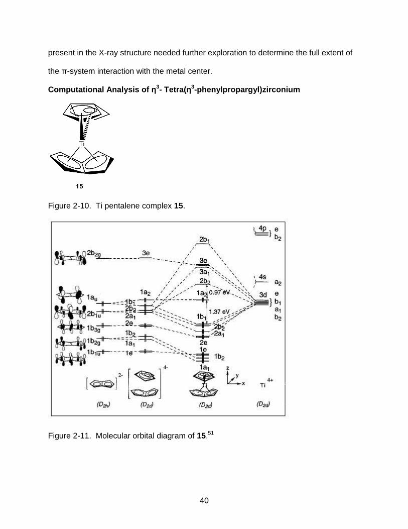
Figure 2-10. Ti pentalene complex 15.
Figure 2-11. Molecular orbital diagram of 15.51
41
Group IV D2d metal complexes with conjugated π-systems are known in the
literature.51-53 The pentalene complex 15 (Figure 2-10) has a unique type of bonding
that suggested an electron count of 20 for the metal.
Calculations showed that was not actually the case, due to a folding distortion of
the pentalene ring that resulted in an overall electron count of 18.51 A molecular orbital
(MO) diagram was generated from the computational analysis (Figure 2-1151).
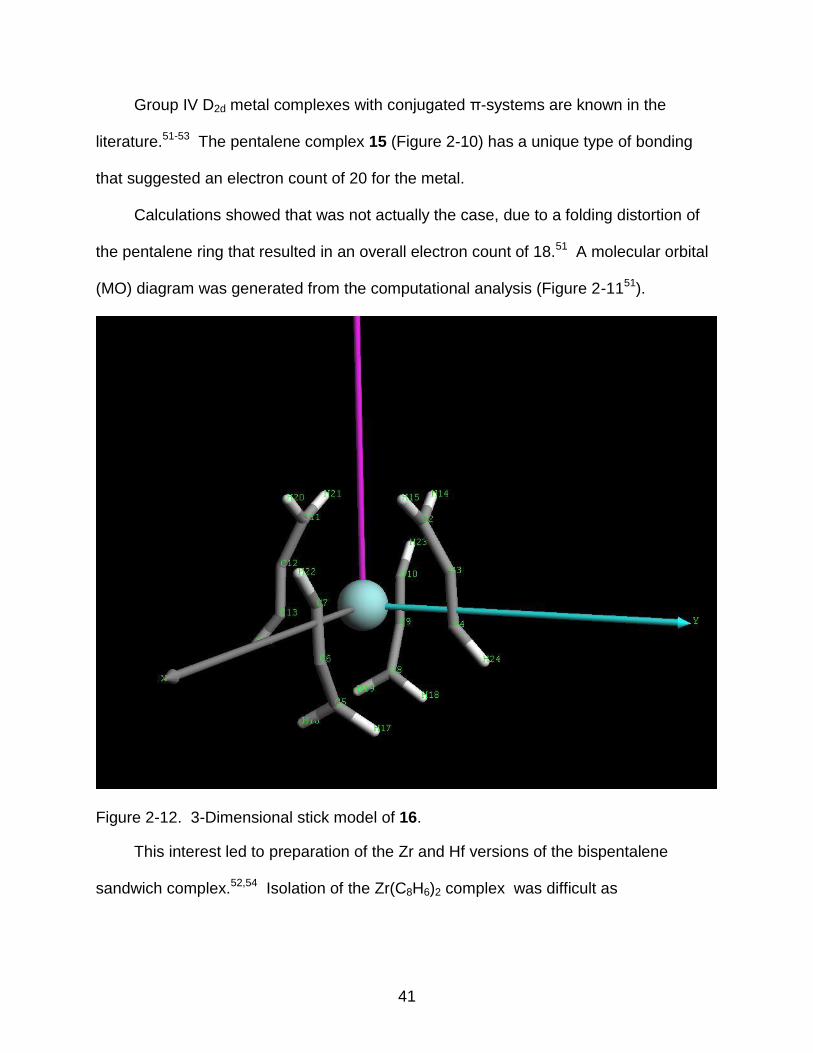
Figure 2-12. 3-Dimensional stick model of 16.
This interest led to preparation of the Zr and Hf versions of the bispentalene
sandwich complex.52,54 Isolation of the Zr(C8H6)2 complex was difficult as

42
decomposition readily occurred at room temperature. 13C NMR suggested an overall
staggered structure of the two rings, but this could not be confirmed by X-ray analysis.52
The complex π-system seen in 11 was analyzed by density functional theory
(DFT) calculations (B3LYP/LANL2DZ), to better understand the bonding shown in the
X-ray crystal structure.55-58 Initial calculations were performed on 11, but the
contribution of the phenyl rings complicated the results by delocalizing the molecular
orbitals to such an extent that visualization of them was difficult. To help simplify the
visualization, the phenyl rings were replaced with hydrogen to give 16 which is also of
D2d symmetry (Figure 2-12).
Figure 2-13. Molecular orbital diagram of 16.

43
The molecular orbital diagram in Figure 2-13 was generated from the
computational results. The calculated HOMO-LUMO gap was 5.2 eV. This was
considerably larger than that obtained for D2d symmetric 15, which had a calculated
band gap of 1.93 eV,51 presumably due to the extensive conjugation in the molecule.
Such a large HOMO-LUMO gap for 16 also helps explain the lack of color of the solid
state in 11, which is a transparent-to-translucent white depending on the degree of
crystallinity in the solid.
Figure 2-14. Degenerate HOMO orbitals of 16.
The orbital contributions and images were also obtained. Select contributions are
given below with the percent contribution listed in parentheses. The HOMO, comprised
of two degenerate orbitals, contains the p-orbitals of the terminal carbons of the
propargyl ligand that intersect the yz plane due to the interaction from the dzy orbital on
Zr (20.7%) (Figure 2-14). The other degenerate orbital uses dxz of Zr (20.7%) instead.
The HOMO-2 (not pictured) is mainly comprised of dz2 on Zr (21.3%) and the xy plane
of the p orbitals on the propargyl ligand.

44
The LUMO of 16 is mainly composed of many small interactions but has the
strongest p-orbital contributions from the central carbon in the propargyl groups. The
largest contributions of Zr are s (14.2%) and dz2 (6.2%) (Figure 2-15). The LUMO+1 is
mainly comprised of the dxy orbital of Zr (76.1%). The LUMO+2 is comprised of two
degenerate orbitals, one is composed primarily of dxz (25.3%) and the other dyz (25.3%),
(Figure 2-16).
Figure 2-15. LUMO and LUMO+1 orbitals of 16. Left) LUMO. Right) LUMO+1.
The somewhat minor contributions from the orbitals are to be expected as this
compound has a large π-system which disperses electron density. However, this does
give excellent insight as to which orbitals are involved in the bonding and allows for an
intellectual construct to help better understand the orbital interactions. It is interesting
that this early transition metal 16-electron complex does not have an empty coordination
site due to its symmetry. Complex 11 was also crystallized from THF with vapor
diffusion of pentanes and did not show any coordinated THF in either the 1H NMR or the

45
X-ray crystal structure. It is also possible that the large steric bulk afforded by the
phenyl rings helps to exclude coordinating solvents.
Figure 2-16. Degenerate LUMO+2 orbitals of 16.
An electronically similar π-system is found in tetra-η3-allylzirconium. Although the
complex was first reported in 1966,59 the complex is not well characterized owing to its
ready decomposition at temperatures above -20 °C.
Spectroscopic 1H NMR studies indicated that the allyl ligands do undergo internal
rotation about the methylene carbon at temperatures above -70 °C. The material itself
is a bright red solid, indicating that the HOMO-LUMO gap in the substance is low
enough to allow LMCT. Compared with 11, which is a white solid at room temperature,
the HOMO-LUMO gap in tetra-η3-allylzirconium must be considerably lower. A solid
state comparison between the two is not possible as tetra-η3-allylzirconium decomposes
when placed on a microscope slide even when kept cool.60
46
Conclusions
Attempts at gaining insight in the decomposition mechanism of ZrNp4 toward
deposition of ZrC were undertaken with the synthesis of 2 and 10, however a suitable
mass spectral analysis was unable to be obtained due to the high sensitivity of the
compounds to air and moisture.
The synthesis of 11 has yielded the first known example of a homoleptic
propargylzirconium complex. The X-ray analysis has shown this complex to be
structurally interesting with D2d symmetry. The extent of the π-system in bonding was
investigated by computational analysis and indicated that the molecule had an
exceptionally large HOMO-LUMO gap of 5.3 eV. The high symmetry enabled wide
dispersion of electron density greatly stabilizing the molecule. The HOMO was found to
be comprised of two degenerate orbitals and the main orbital interactions with Zr are dyz
and dxz, respectively. The LUMO was found to be mainly focused around the central
carbons in the propargyl ligands and comprised of s and dz2 interactions with Zr. The
LUMO +1 was found to be comprised of and dxy orbitals. The LUMO+2 was found to be
degenerate and comprised of dxz and dzy orbitals.
47
CHAPTER 3 TRANSITION METAL-CATALYZED OXIDATIVE CARBONYLATION OF AMINES TO
UREAS
Introduction and Background
The presence of urea moieties in molecules of interest in a wide range of fields
and applications has stimulated interest in their synthesis. Much development into the
synthesis of this particular functional group has occurred as it is seen in
pharmaceuticals,61-65 agrochemicals, precursors of resins, dyes, and additives to both
petrochemicals and polymers.66 Of particular interest has been their usage as non-
protein based HIV protease inhibitors, CCK-B receptor antagonists, and endothelin
antagonists.63,67-70 Ureas themselves can also be synthons for other bulk chemicals by
thermal cracking to yield isocyanates71 or reacting with alcohols to yield carbamates.72
The traditional synthesis of ureas has been accomplished with the nucleophilic
attack of amines on phosgene and its derivatives or isocyanates.73,74 Phosgene is very
reactive with both primary and secondary amines, and arrives at the product urea very
well. However, phosgene is a highly toxic and corrosive gas that requires special
handling and equipment. This has greatly discouraged its use in the laboratory setting.
The production of phosgene on an industrial scale also includes serious risks to both
safety of personnel and the environment in its usage, storage, and transportation.75
Derivatives of phosgene are safer in all three of the above mentioned categories and
include 1,1-carbonyldiimidazole, triphosgene, and many others. These are more
common for use in laboratory scale synthesis than in industrial applications, as each
equivalent of phosgene derivative used produces two equivalents of the leaving group.
The generation of a large waste stream of byproducts is problematic with phosgene
48
derivatives on an industrial scale, but not with phosgene itself as only aqueous chloride
is produced.
Other synthetic methods employed to convert amines to ureas include reaction
with isocyanates and chloroformates. Isocyanates themselves are mainly derived from
phosgene and are very toxic. Phenyl chloroformate has also been used, but has
drawbacks as DMSO is the required solvent. In both laboratory and industrial scales,
DMSO poses large risks to its potentially carcinogenic nature and because of its high
boiling point making solvent removal very difficult.
Synthesis of ureas with phosgene also poses other synthetic problems due to its
high reactivity. Unwanted side reactions involving nucleophilic functional groups, such
as hydroxyl groups, can be a problem and require extensive protection/deprotection
steps to avoid. Alternative routes have actively been sought that utilize either CO or
CO2 as the source of the carbonyl moiety.75 These do not have the same problems of
functional group compatibility and are generally safer to conduct, especially upon scale
up.76,77 The desire for catalytic systems as an alternative to stoichiometric reagents is
evident and has been explored. Catalytic systems are also attractive from an atom
economy78 standpoint as catalytic oxidative carbonylation systems only employ amine,
carbon monoxide, and some form of oxidant, which in turn only produces the reduced
form of the oxidant and protons.79,80
With this in mind, the McElwee-White group reported the catalytic oxidative
carbonylation of amines using a system comprised of W(CO)6 as the catalyst, I2, as the
oxidant, and some form of base. This has been shown to convert primary amines,81
secondary amines,82 diamines,83 and amino-alcohols to the corresponding ureas in the
49
presence of CO.77 These reaction conditions tend to be relatively mild and have been
shown to be highly tolerant of various functional groups.84
The use of the W(CO)6/I2 system is advantageous as the reagents are readily
available commercially and are easy to handle. It provides an excellent laboratory scale
alternative to urea synthesis from phosgene and its derivatives given its compatibility
with functional groups. The remainder of this work will focus on the applications of the
W(CO)6/I2 catalyzed carbonylation system to complex substrates.
Transition Metal Catalysts
New synthetic methods for preparing carbonyl-nitrogen bond moieties utilizing the
metal-catalyzed carbonylation of amines are numerous and extensively studied. Mono-
and dicarbonylation of amines have been reported as catalyzed by complexes of
Mn,85,86 Fe,87 Co,88-92 Ni,93,94 Ru,71,95-98 Rh,89,98,99 Pd,71,100-112 W,76,77,81-84,113 Pt,114 Ir,114
and Au.115,116 The products of these carbonylations include ureas,71,86,89,90,93,98
urethanes,92,117 oxamides,118 formamides,119-123 and oxazolidinones.92,124 The
conditions reported for these, in general, include elevated temperatures and moderate-
to-high pressures of CO. Highlighted advances in transition metal catalyzed oxidative
carbonylation of amines will be presented in this section.
Palladium-Catalyzed Oxidative Carbonylation of Amines
The Tsuji group first reported Pd-catalyzed carbonylation of amines in 1966.109
Since then it has been extensively studied and recently reviewed.71,80 Methods for
oxidative carbonylation utilizing copper oxidants or O2 as the terminal oxidant and CuX
or CuX2 mediating have been utilized effectively with PdCl2 to form ureas,125-127
carbamates,100,128 and oxamides.100,129-131 Non-metal oxidants have also been used
effectively including desyl chloride to generate carbamates from In-based alkylating

50
reagents and PdCl2 and phosphine ligands.111 The use of 1,4-dichloro-2-butene (DCB)
as oxidant with the catalyst PdCl2(PPh3)2 has been found to afford oxamides while using
the oxidant I2 yielded ureas from primary and secondary amines.118
Heterogenous carbonylations of amines to ureas
The first oxidative carbonylations of alkylamines using Pd/C as a catalyst were
reported by Fukuoka132 and Chaudhari.133 The reactions were successful in the
presence of promoter iodide salts and O2, to afford ureas and carbamates in good
yields. Similarly, Gabriele reported the use of PdI2 and O2 for the formation of ureas
and cyclic carbamates from amines,134 high yields and turnover numbers over 4900
were obtained (Figure 3-1).103,135
Figure 3-1. Oxidative carbonylation of alkylamines using a PdI2 and KI system.103
Primary aliphatic amines (Eq. 3-1, R = alkyl) were carbonylated at 100 °C under
elevated pressure with an atmosphere comprised of a 4:1:10 mixture of CO:air:CO2 in
the presence of a catalytic system comprised of PdI2 utilizing KI as a promoter. The
presence of CO2 proved crucial to obtain higher yields. Solvent choice also dictated
selectivity observed in the reaction. Urea formation was favored by using dioxane and
glyme, while the oxamide predominated in much more polar solvents including N,N-
dimethylacetamide (DMA) or N-methylpyrrolidinone (NMP).135 It was postulated that the
more polar solvents favored the formation of the intermediate Pd(CONHBu)2, which
then underwent reductive elimination to form the oxamide. Primary aromatic amines
were also tested and found to be less reactive than their alkyl counterparts, unless
51
electron-donating groups were present on the aromatic ring, increasing their
nucleophilicity.
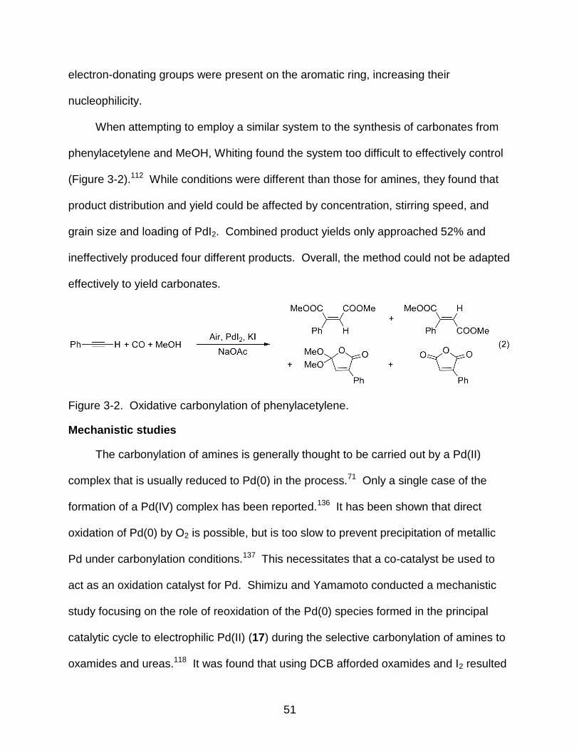
When attempting to employ a similar system to the synthesis of carbonates from
phenylacetylene and MeOH, Whiting found the system too difficult to effectively control
(Figure 3-2).112 While conditions were different than those for amines, they found that
product distribution and yield could be affected by concentration, stirring speed, and
grain size and loading of PdI2. Combined product yields only approached 52% and
ineffectively produced four different products. Overall, the method could not be adapted
effectively to yield carbonates.
Figure 3-2. Oxidative carbonylation of phenylacetylene.
Mechanistic studies
The carbonylation of amines is generally thought to be carried out by a Pd(II)
complex that is usually reduced to Pd(0) in the process.71 Only a single case of the
formation of a Pd(IV) complex has been reported.136 It has been shown that direct
oxidation of Pd(0) by O2 is possible, but is too slow to prevent precipitation of metallic
Pd under carbonylation conditions.137 This necessitates that a co-catalyst be used to
act as an oxidation catalyst for Pd. Shimizu and Yamamoto conducted a mechanistic
study focusing on the role of reoxidation of the Pd(0) species formed in the principal
catalytic cycle to electrophilic Pd(II) (17) during the selective carbonylation of amines to
oxamides and ureas.118 It was found that using DCB afforded oxamides and I2 resulted
52
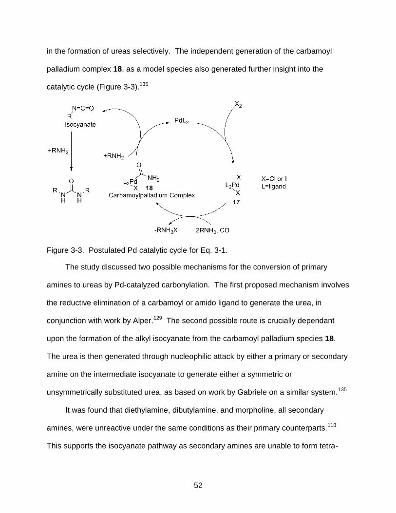
in the formation of ureas selectively. The independent generation of the carbamoyl
palladium complex 18, as a model species also generated further insight into the
catalytic cycle (Figure 3-3).135
Figure 3-3. Postulated Pd catalytic cycle for Eq. 3-1.
The study discussed two possible mechanisms for the conversion of primary
amines to ureas by Pd-catalyzed carbonylation. The first proposed mechanism involves
the reductive elimination of a carbamoyl or amido ligand to generate the urea, in
conjunction with work by Alper.129 The second possible route is crucially dependant
upon the formation of the alkyl isocyanate from the carbamoyl palladium species 18.
The urea is then generated through nucleophilic attack by either a primary or secondary
amine on the intermediate isocyanate to generate either a symmetric or
unsymmetrically substituted urea, as based on work by Gabriele on a similar system.135
It was found that diethylamine, dibutylamine, and morpholine, all secondary
amines, were unreactive under the same conditions as their primary counterparts.118
This supports the isocyanate pathway as secondary amines are unable to form tetra-
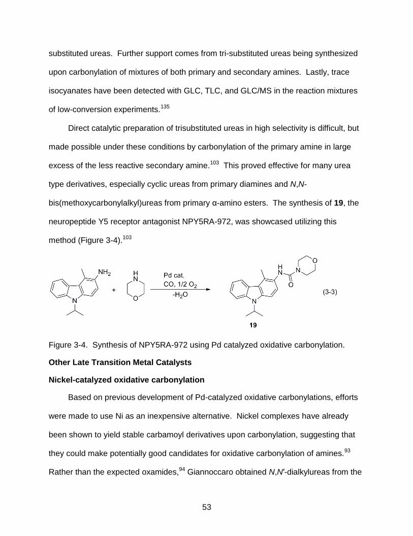
53
substituted ureas. Further support comes from tri-substituted ureas being synthesized
upon carbonylation of mixtures of both primary and secondary amines. Lastly, trace
isocyanates have been detected with GLC, TLC, and GLC/MS in the reaction mixtures
of low-conversion experiments.135
Direct catalytic preparation of trisubstituted ureas in high selectivity is difficult, but
made possible under these conditions by carbonylation of the primary amine in large
excess of the less reactive secondary amine.103 This proved effective for many urea
type derivatives, especially cyclic ureas from primary diamines and N,N-
bis(methoxycarbonylalkyl)ureas from primary α-amino esters. The synthesis of 19, the
neuropeptide Y5 receptor antagonist NPY5RA-972, was showcased utilizing this
method (Figure 3-4).103
Figure 3-4. Synthesis of NPY5RA-972 using Pd catalyzed oxidative carbonylation.
Other Late Transition Metal Catalysts
Nickel-catalyzed oxidative carbonylation
Based on previous development of Pd-catalyzed oxidative carbonylations, efforts
were made to use Ni as an inexpensive alternative. Nickel complexes have already
been shown to yield stable carbamoyl derivatives upon carbonylation, suggesting that
they could make potentially good candidates for oxidative carbonylation of amines.93
Rather than the expected oxamides,94 Giannoccaro obtained N,N′-dialkylureas from the

54
reaction of primary amines with the nickel amine complexes NiX2(RNH2)4 (X = Cl, Br; R
= alkyl). At temperatures above 50 °C side reactions became competitive.
Figure 3-5. Nickel catalyzed oxidative carbonylation of amines.
At lower temperatures the reductive elimination of the oxamide did not occur.
Selectivity between urea and oxamide was accomplished by controlling the amount of
water present in the reaction. The presence of water afforded urea formation and
anhydrous conditions yielded oxamide (Figure 3-5).93 It was suggested that under
aqueous conditions, water could coordinate to the Ni center and prevent more than one
carbamoyl from forming. This intermediate would then be susceptible to nucleophilic
attack from free amine, yielding the urea. Without the presence of water, two
carbamoyls can form and reductively eliminate to form the oxamide.93
Ruthenium-catalyzed oxidative carbonylation
The oxidative carbonylation of aniline catalyzed by [Ru(CO)3I3]NBu4 utilizing NiI as
the promoter forms N,N′-diphenylurea (DPU) 99% selectively, as shown by Gupte.98
The key step (Figure 3-6) is the formation of the carbamoylruthenium intermediate 24.

55
Loss of CO from the catalyst precursor [Ru(CO)3I3]- 20 generates the ruthenium
dicarbonyl intermediate 21 which then becomes susceptible to nucleophilic attack by
aniline to form the aminoruthenium dicarbonyl species 22 and HI. Addition of CO to
produce 23 is followed by insertion to afford the carbamoyl complex 24. This then
reacts with aniline to form both the product urea and the hydrido carbonyl species 25.
Addition of aniline yields 26, which is oxidized by O2 to regenerate the active species.98
Similar results utilizing alkylamines have also been reported.133,138
Figure 3-6. Oxidative carbonylation of arylamines using ruthenium catalysts.97
Cobalt- and rhodium-catalyzed oxidative carbonylation
The synthesis of acyclic and cyclic ureas from primary aromatic amines was
accomplished by Rindone using N,N′-bis(salicylidene)ethylenediaminocobalt(II)
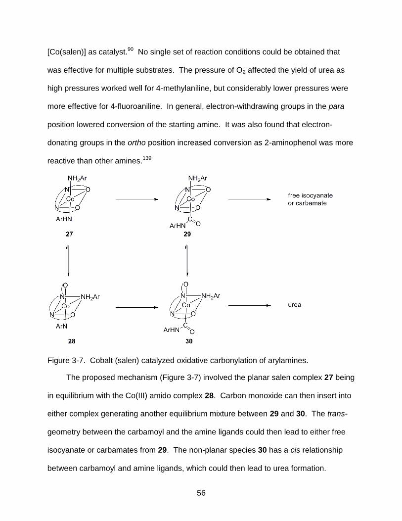
56
[Co(salen)] as catalyst.90 No single set of reaction conditions could be obtained that
was effective for multiple substrates. The pressure of O2 affected the yield of urea as
high pressures worked well for 4-methylaniline, but considerably lower pressures were
more effective for 4-fluoroaniline. In general, electron-withdrawing groups in the para
position lowered conversion of the starting amine. It was also found that electron-
donating groups in the ortho position increased conversion as 2-aminophenol was more
reactive than other amines.139
Figure 3-7. Cobalt (salen) catalyzed oxidative carbonylation of arylamines.
The proposed mechanism (Figure 3-7) involved the planar salen complex 27 being
in equilibrium with the Co(III) amido complex 28. Carbon monoxide can then insert into
either complex generating another equilibrium mixture between 29 and 30. The trans-
geometry between the carbamoyl and the amine ligands could then lead to either free
isocyanate or carbamates from 29. The non-planar species 30 has a cis relationship
between carbamoyl and amine ligands, which could then lead to urea formation.
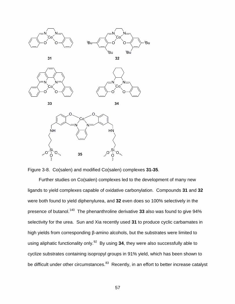
57
Figure 3-8. Co(salen) and modified Co(salen) complexes 31-35.
Further studies on Co(salen) complexes led to the development of many new
ligands to yield complexes capable of oxidative carbonylation. Compounds 31 and 32
were both found to yield diphenylurea, and 32 even does so 100% selectively in the
presence of butanol.140 The phenanthroline derivative 33 also was found to give 94%
selectivity for the urea. Sun and Xia recently used 31 to produce cyclic carbamates in
high yields from corresponding β-amino alcohols, but the substrates were limited to
using aliphatic functionality only.92 By using 34, they were also successfully able to
cyclize substrates containing isopropyl groups in 91% yield, which has been shown to
be difficult under other circumstances.83 Recently, in an effort to better increase catalyst

58
recovery, Co(salen) catalysts were covalently bonded to a silica matrix via a sol-gel
process.88 The heterogeneous catalyst 35 was used for the oxidative carbonylation of
carbamates from aniline and methanol. While the reaction only produced a 60% yield of
carbamate, it was able to be recovered five times with only a small drop in catalytic
activity to still afford the product in 50% yield.
Figure 3-9. Rh-catalyzed oxidative carbonylation of aniline to DPU.141
Investigations of rhodium-catalyzed carbonylation of amines to ureas have been
sparse recently. Chaudhari initially used Rh/C-NaI to make carbamates, but found
some conditions that favored formation of ureas.142 However, DMF was required as
solvent to achieve urea synthesis, and all other solvents tested gave the carbamate
product. Giannoccaro found that materials containing simple Rh3+ salts worked well for
carbonylation of aniline to form DPU. The catalytic system worked better when
intercalated with γ-titanium phosphate to make a heterogeneous system. A mechanism
was postulated (Figure 3-9) and the key intermediate appears to be the Rh3+-carbamoyl
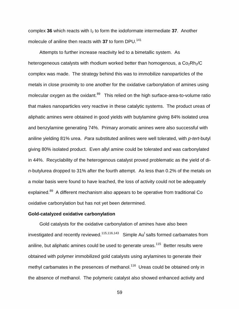
59
complex 36 which reacts with I2 to form the iodoformate intermediate 37. Another
molecule of aniline then reacts with 37 to form DPU.141
Attempts to further increase reactivity led to a bimetallic system. As
heterogeneous catalysts with rhodium worked better than homogenous, a Co2Rh2/C
complex was made. The strategy behind this was to immobilize nanoparticles of the
metals in close proximity to one another for the oxidative carbonylation of amines using
molecular oxygen as the oxidant.89 This relied on the high surface-area-to-volume ratio
that makes nanoparticles very reactive in these catalytic systems. The product ureas of
aliphatic amines were obtained in good yields with butylamine giving 84% isolated urea
and benzylamine generating 74%. Primary aromatic amines were also successful with
aniline yielding 81% urea. Para substituted anilines were well tolerated, with p-tert-butyl
giving 80% isolated product. Even allyl amine could be tolerated and was carbonylated
in 44%. Recyclability of the heterogenous catalyst proved problematic as the yield of di-
n-butylurea dropped to 31% after the fourth attempt. As less than 0.2% of the metals on
a molar basis were found to have leached, the loss of activity could not be adequately
explained.89 A different mechanism also appears to be operative from traditional Co
oxidative carbonylation but has not yet been determined.
Gold-catalyzed oxidative carbonylation
Gold catalysts for the oxidative carbonylation of amines have also been
investigated and recently reviewed.115,116,143 Simple AuI salts formed carbamates from
aniline, but aliphatic amines could be used to generate ureas.115 Better results were
obtained with polymer immobilized gold catalysts using arylamines to generate their
methyl carbamates in the presences of methanol.116 Ureas could be obtained only in
the absence of methanol. The polymeric catalyst also showed enhanced activity and

60
ease of separation from the product compared to those gold catalysts previously
reported. It was later shown that this reaction is capable of forming dialkylureas in high
yield with high turnover frequencies, and worked in the presence of CO2 as reactant,
(Figure 3-10).143 The exact mechanism for this reaction is still unknown.
Figure 3-10. Polymer supported Au-catalyzed carbonylation of amines.
Tungsten-Catalyzed Oxidative Carbonylation of Amines
Carbonylation of primary amines
Examples of Group 6 metal complexes for the catalytic carbonylation of amines
are rare. The initial report by McElwee-White utilized primary amines for catalytic
oxidative carbonylation using the iodo-bridged tungsten dimer [(CO)2W(NPh)I2]2 (38) as
the precatalyst (Figure 3-11).81 Those studies showed that primary aromatic and
aliphatic amines could be carbonylated to the corresponding disubstituted urea, while
secondary amines yielded modest amounts of formamides.
Mechanistic studies determined that primary amines reacted stoichiometrically
with dimer 38 to yield the amine complexes (CO)2I2W(NPh)(NH2R), 39. In the presence
of an oxidant, these undergo nucleophilic attack by excess free amine to give the
ureas.81 The carbonyl ligand in 40 is susceptible to nucleophilic attack followed by
proton abstraction from a second equivalent of amine to afford 41. The reaction mixture
was tested by FT-IR and indicated the presence of a carbamoyl species, as
precedented from results from Angelici on the carbonylation of methylamine by [(η5-
C5H5)W(CO)4]PF6.144 In that case, it was shown that the first step is conversion of [(η5-
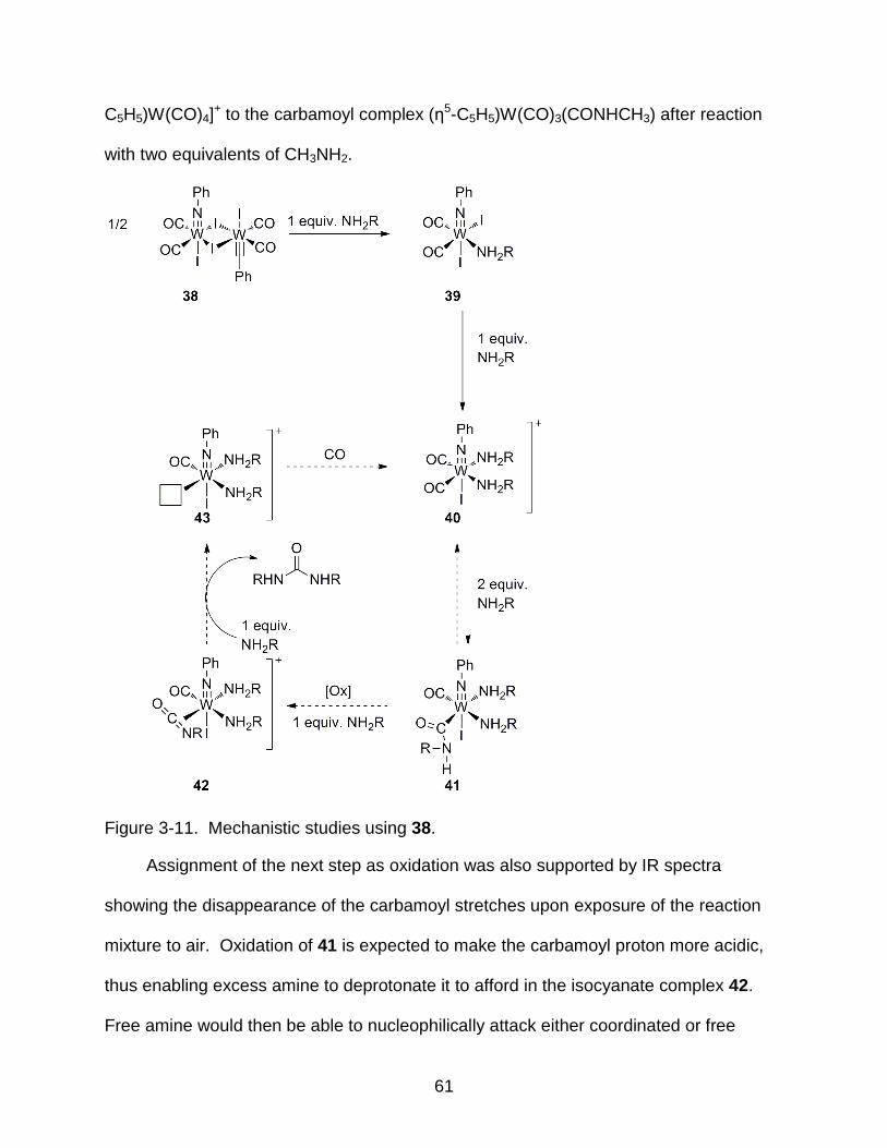
61
C5H5)W(CO)4]+ to the carbamoyl complex (η5-C5H5)W(CO)3(CONHCH3) after reaction
with two equivalents of CH3NH2.
Figure 3-11. Mechanistic studies using 38.
Assignment of the next step as oxidation was also supported by IR spectra
showing the disappearance of the carbamoyl stretches upon exposure of the reaction
mixture to air. Oxidation of 41 is expected to make the carbamoyl proton more acidic,
thus enabling excess amine to deprotonate it to afford in the isocyanate complex 42.
Free amine would then be able to nucleophilically attack either coordinated or free

62
isocyanate to afford the disubstituted urea and also the coordinatively unsaturated
complex 43. Addition of CO would then regenerate the cationic species 40 and
complete the catalytic cycle.
These results suggested that other tungsten carbonyl iodide complexes might also
serve as catalysts. The choice to test W(CO)6 as precatalyst was simple as it is
commercially available, inexpensive, and air stable. Preliminary reactions using
W(CO)6, 100 equivalents of n-butylamine, 50 equivalents of iodine, and 100 equivalents
of K2CO3 in a 125 mL Parr high-pressure autoclave pressurized with 100 atm CO
produced di-n-butylurea in 80% yield with respect to amine, corresponding to 39
turnovers per equivalent of W(CO)6.
Table 3-1. Oxidative carbonylation of primary amines to ureas under optimized conditions
Amine Product %Yield in CH2Cl2
90
84
53
55
72
0
The W(CO)6/I2 system was subsequently optimized with n-propylamine and it was
found that N,N′-disubstituted ureas could be obtained in good to excellent yields (Table
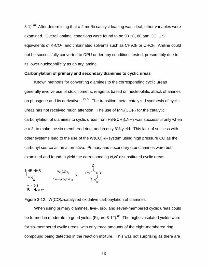
63
3-1).70 After determining that a 2 mol% catalyst loading was ideal, other variables were
examined. Overall optimal conditions were found to be 90 °C, 80 atm CO, 1.5
equivalents of K2CO3, and chlorinated solvents such as CH2Cl2 or CHCl3. Aniline could
not be successfully converted to DPU under any conditions tested, presumably due to
its lower nucleophilicity as an aryl amine.
Carbonylation of primary and secondary diamines to cyclic ureas
Known methods for converting diamines to the corresponding cyclic ureas
generally involve use of stoichiometric reagents based on nucleophilic attack of amines
on phosgene and its derivatives.73,74 The transition metal-catalyzed synthesis of cyclic
ureas has not received much attention. The use of Mn2(CO)10 for the catalytic
carbonylation of diamines to cyclic ureas from H2N(CH2)nNH2 was successful only when
n = 3, to make the six membered ring, and in only 6% yield. This lack of success with
other systems lead to the use of the W(CO)6/I2 system using high pressure CO as the
carbonyl source as an alternative. Primary and secondary α,ω-diamines were both
examined and found to yield the corresponding N,N′-disubstituted cyclic ureas.
Figure 3-12. W(CO)6-catalyzed oxidative carbonylation of diamines.
When using primary diamines, five-, six-, and seven-membered cyclic ureas could
be formed in moderate to good yields (Figure 3-12).83 The highest isolated yields were
for six-membered cyclic ureas, with only trace amounts of the eight-membered ring
compound being detected in the reaction mixture. This was not surprising as there are
64
no reports in the literature of the preparation of this compound from 1,5-
pentanediamine. A 2-imidazolidinone derivative could be synthesized using this method
from (+)-(1R,2R)-1,2-diphenyl-1,2-ethanediamine in 46% yield. Secondary diamines of
the form RNHCH2CH2NHR (Figure 3-12, R-Me, Et, iPr, Bn) under similar conditions
resulted in the formation of the corresponding N,N′-disubstituted cyclic ureas. The
formation of oligomers upon carbonylation of both primary and secondary diamines was
problematic, but could be overcome by employing high dilution. This strategy also been
reported in the use of phosgene and its derivatives with diamines.145
An examination of steric effects on the ring closure was also undertaken using
N,N′-dimethyl, diethyl, diisopropyl, and dibenzyl diamines under the standard conditions
yielding both the dimethyl- and diethyl-cyclic ureas in nearly identical yields. The use of
benzyl groups had only a minor lowering effect on the yield, but the use of isopropyl
groups drastically lowered the yield of the imidazolidinone to only 10%. These steric
effects could not be overcome by raising reaction temperatures. An interesting
competition experiment yielded that when N-methylpropanediamine was reacted under
the oxidative carbonylation conditions, the corresponding monosubstituted N-methyl
cyclic urea was formed in preference to acyclic urea formation through the much more
reactive primary amine.83
Further optimization of the carbonylation conditions for the conversion of α,ω-
diamines to cyclic ureas used propane-1,3-diamine, W(CO)6 as catalyst, and I2 as the
oxidant for tests of solvent effects and temperature variation.70 Additional experiments
on the effect of alkyl substituents in the linker of primary diamines were conducted
(Table 3-2).83
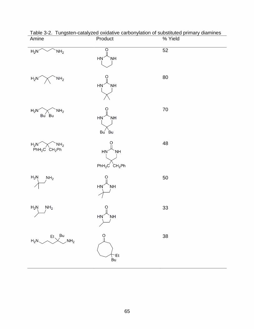
65
Table 3-2. Tungsten-catalyzed oxidative carbonylation of substituted primary diamines
Amine Product % Yield
52
80
70
48
50
33
38

66
Simple n-alkyl substitution had dramatic effects on cyclic urea formation. 2,2-
Dialkyl-1,3-propanediamines gave increased yields as compared to the parent propane-
1,3-diamine as a result of the Thorpe-Ingold effect146 and the enhanced solubility of the
product resulting in simplification of the reaction workup.
The carbonylation of N,N′-dialkyl-2,2-dimethylpropane-1,3-diamines afforded
tetrasubstituted ureas, but only in modest yields. Tetrahydropyrimidine byproducts were
formed in significant amounts when the N-alkyl substituents were larger than methyl.
When compared to the results obtained with carbonylations of secondary diamines to
form five-membered cyclic ureas, the effects of the dimethyl substitution on ring size
and those of the N-substituents are complex.
As cyclic ureas could be synthesized from the corresponding diamines, more
complex synthetic targets were considered. However, no experiments on functional
group tolerance had been conducted, and this tends to be an issue with early transition
metals. Functional group compatibility was examined using a series of substituted
benzylamines (Figure 3-13).84
Figure 3-13. W(CO)6-catalyzed carbonylation of substituted benzylamines.
The groups tested (Table 3-384) demonstrated that the oxidative carbonylation of
amines using the W(CO)6/I2 system was tolerant of a wide variety of functional groups.
Amines containing substituents such as halides, esters, alkenes, and nitriles on the
benzyl amine were successfully carbonylated to the corresponding ureas in moderate to
good yields.

67
Table 3-3. Catalytic carbonylation of substituted benzylamines to ureas
Amine % Yield[a] Yield[b] Amine % Yield[a] % Yield[b]
63 73
36 55
35 77
0 37
30 77
41 69
39 70
41 69
47 70
37 68
24 81
28 14
5 58
17 20
0 0
a Reaction conditions: amine (7.1 mmol), W(CO)6 (0.14 mmol), I2 (3.5 mmol), K2CO3 (10.7 mmol), CH2Cl2
(20 mL), 70 °C, 80 atm CO, 24 h. b The solvent was CH2CH2 (21 mL) plus H2O (3 mL). Other conditions are as in footnote a.
84
The presence of unprotected alcohols had been shown to be a problem using
phosgene derivatives,84 however, this was not the case in the tungsten system.
Changing the reaction medium to using a biphasic solvent system produced a dramatic
change in the yields of these functionalized ureas. This system provided solubility for
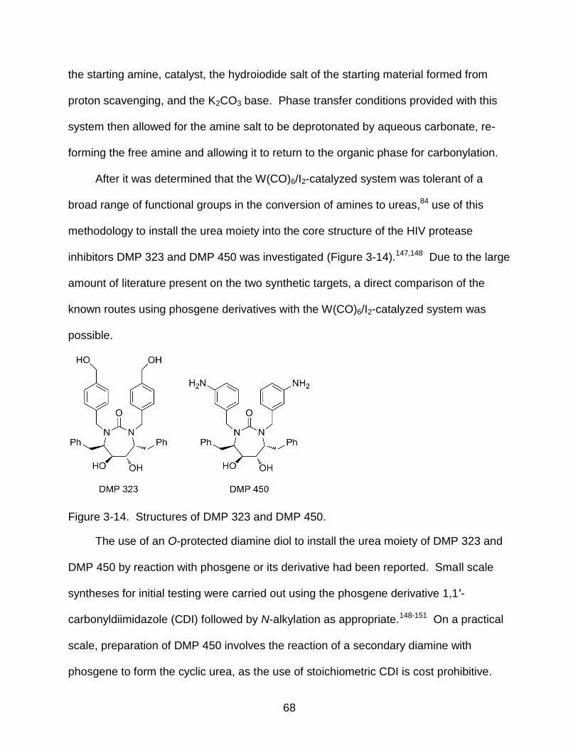
68
the starting amine, catalyst, the hydroiodide salt of the starting material formed from
proton scavenging, and the K2CO3 base. Phase transfer conditions provided with this
system then allowed for the amine salt to be deprotonated by aqueous carbonate, re-
forming the free amine and allowing it to return to the organic phase for carbonylation.
After it was determined that the W(CO)6/I2-catalyzed system was tolerant of a
broad range of functional groups in the conversion of amines to ureas,84 use of this
methodology to install the urea moiety into the core structure of the HIV protease
inhibitors DMP 323 and DMP 450 was investigated (Figure 3-14).147,148 Due to the large
amount of literature present on the two synthetic targets, a direct comparison of the
known routes using phosgene derivatives with the W(CO)6/I2-catalyzed system was
possible.
Figure 3-14. Structures of DMP 323 and DMP 450.
The use of an O-protected diamine diol to install the urea moiety of DMP 323 and
DMP 450 by reaction with phosgene or its derivative had been reported. Small scale
syntheses for initial testing were carried out using the phosgene derivative 1,1′-
carbonyldiimidazole (CDI) followed by N-alkylation as appropriate.148-151 On a practical
scale, preparation of DMP 450 involves the reaction of a secondary diamine with
phosgene to form the cyclic urea, as the use of stoichiometric CDI is cost prohibitive.
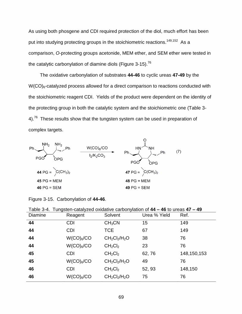
69
As using both phosgene and CDI required protection of the diol, much effort has been
put into studying protecting groups in the stoichiometric reactions.149,152 As a
comparison, O-protecting groups acetonide, MEM ether, and SEM ether were tested in
the catalytic carbonylation of diamine diols (Figure 3-15).76
The oxidative carbonylation of substrates 44-46 to cyclic ureas 47-49 by the
W(CO)6-catalyzed process allowed for a direct comparison to reactions conducted with
the stoichiometric reagent CDI. Yields of the product were dependent on the identity of
the protecting group in both the catalytic system and the stoichiometric one (Table 3-
4).76 These results show that the tungsten system can be used in preparation of
complex targets.
Figure 3-15. Carbonylation of 44-46.
Table 3-4. Tungsten-catalyzed oxidative carbonylation of 44 – 46 to ureas 47 – 49
Diamine Reagent Solvent Urea % Yield Ref.
44 CDI CH3CN 15 149
44 CDI TCE 67 149
44 W(CO)6/CO CH2Cl2/H2O 38 76
44 W(CO)6/CO CH2Cl2 23 76
45 CDI CH2Cl2 62, 76 148,150,153
45 W(CO)6/CO CH2Cl2/H2O 49 76
46 CDI CH2Cl2 52, 93 148,150
46 W(CO)6/CO CH2Cl2/H2O 75 76
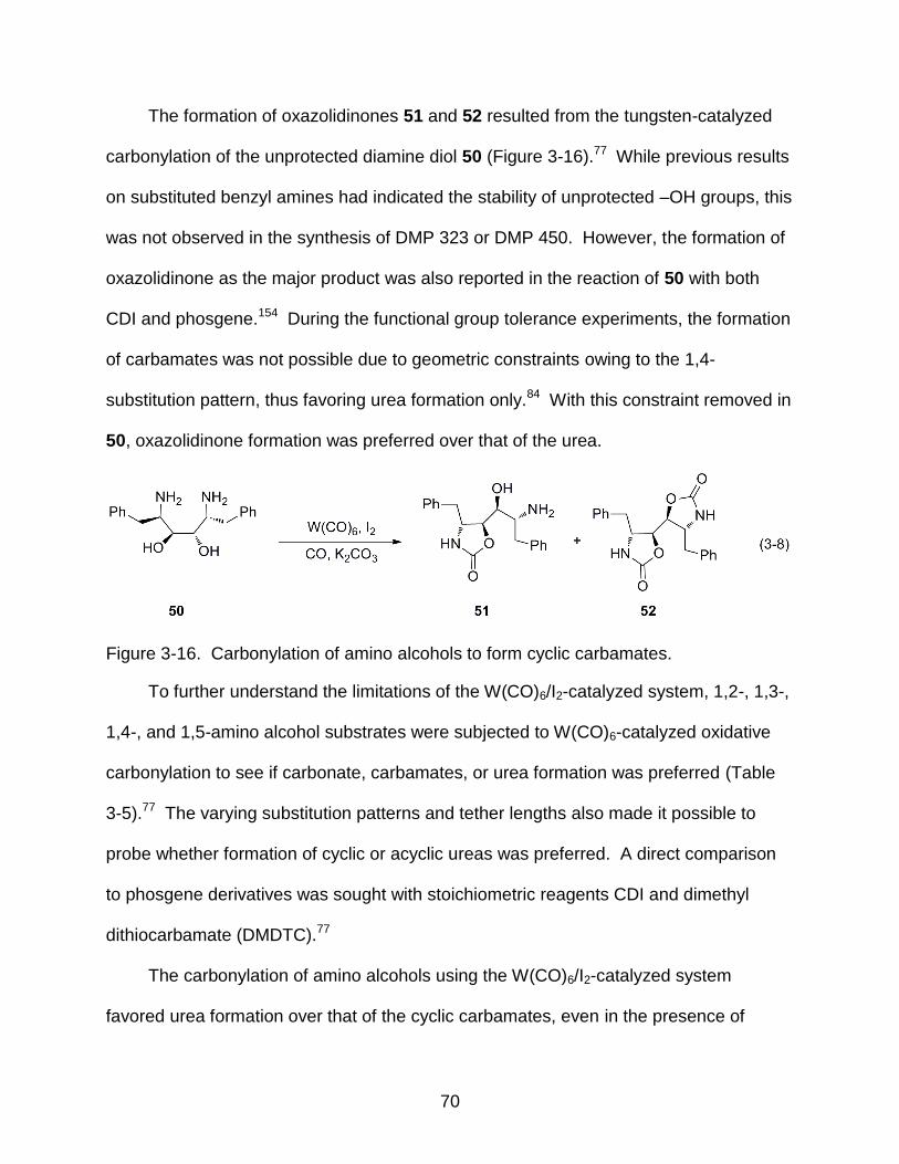
70
The formation of oxazolidinones 51 and 52 resulted from the tungsten-catalyzed
carbonylation of the unprotected diamine diol 50 (Figure 3-16).77 While previous results
on substituted benzyl amines had indicated the stability of unprotected –OH groups, this
was not observed in the synthesis of DMP 323 or DMP 450. However, the formation of
oxazolidinone as the major product was also reported in the reaction of 50 with both
CDI and phosgene.154 During the functional group tolerance experiments, the formation
of carbamates was not possible due to geometric constraints owing to the 1,4-
substitution pattern, thus favoring urea formation only.84 With this constraint removed in
50, oxazolidinone formation was preferred over that of the urea.
Figure 3-16. Carbonylation of amino alcohols to form cyclic carbamates.
To further understand the limitations of the W(CO)6/I2-catalyzed system, 1,2-, 1,3-,
1,4-, and 1,5-amino alcohol substrates were subjected to W(CO)6-catalyzed oxidative
carbonylation to see if carbonate, carbamates, or urea formation was preferred (Table
3-5).77 The varying substitution patterns and tether lengths also made it possible to
probe whether formation of cyclic or acyclic ureas was preferred. A direct comparison
to phosgene derivatives was sought with stoichiometric reagents CDI and dimethyl
dithiocarbamate (DMDTC).77
The carbonylation of amino alcohols using the W(CO)6/I2-catalyzed system
favored urea formation over that of the cyclic carbamates, even in the presence of
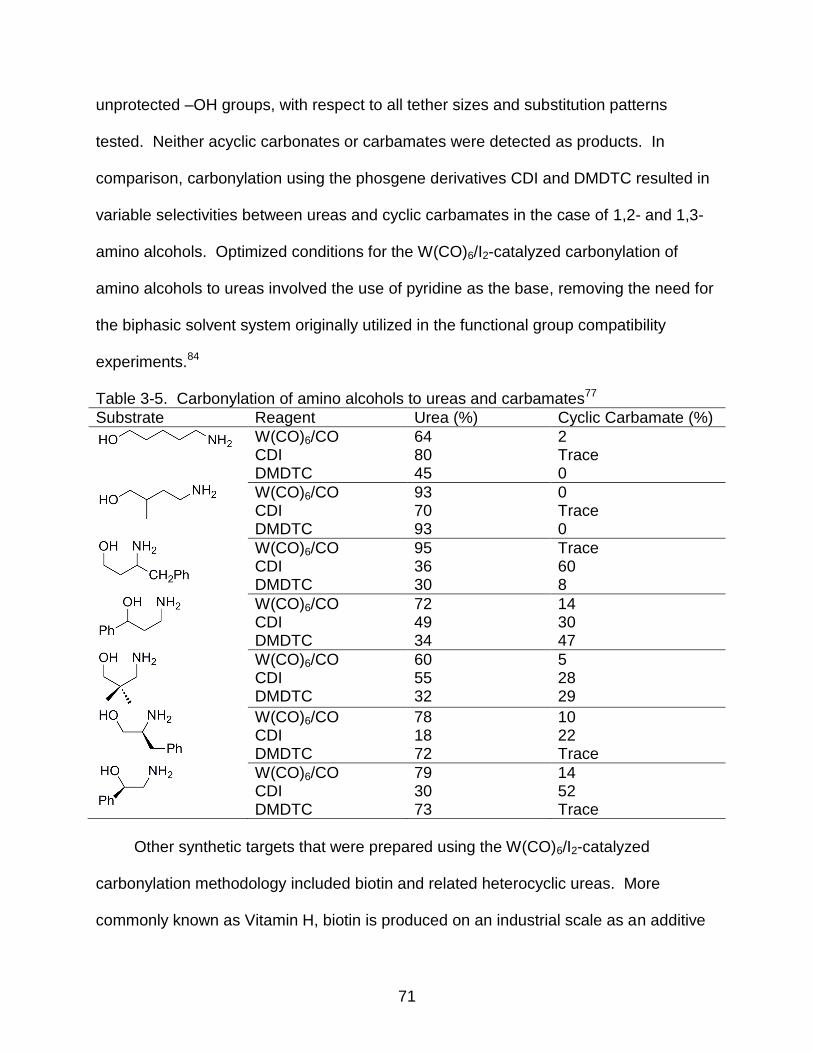
71
unprotected –OH groups, with respect to all tether sizes and substitution patterns
tested. Neither acyclic carbonates or carbamates were detected as products. In
comparison, carbonylation using the phosgene derivatives CDI and DMDTC resulted in
variable selectivities between ureas and cyclic carbamates in the case of 1,2- and 1,3-
amino alcohols. Optimized conditions for the W(CO)6/I2-catalyzed carbonylation of
amino alcohols to ureas involved the use of pyridine as the base, removing the need for
the biphasic solvent system originally utilized in the functional group compatibility
experiments.84
Table 3-5. Carbonylation of amino alcohols to ureas and carbamates77
Substrate Reagent Urea (%) Cyclic Carbamate (%)
W(CO)6/CO CDI DMDTC
64 80 45
2 Trace 0
W(CO)6/CO CDI DMDTC
93 70 93
0 Trace 0
W(CO)6/CO CDI DMDTC
95 36 30
Trace 60 8
W(CO)6/CO CDI DMDTC
72 49 34
14 30 47
W(CO)6/CO CDI DMDTC
60 55 32
5 28 29
W(CO)6/CO CDI DMDTC
78 18 72
10 22 Trace
W(CO)6/CO CDI DMDTC
79 30 73
14 52 Trace
Other synthetic targets that were prepared using the W(CO)6/I2-catalyzed
carbonylation methodology included biotin and related heterocyclic ureas. More
commonly known as Vitamin H, biotin is produced on an industrial scale as an additive

72
to the diet of poultry and swine. Synthesis of biotin has been extensively studied,155 and
the reports commonly employ the formation of the urea moiety by the reaction of
phosgene with a diaminotetrahydrothiophene derivative. Biotin itself could not be
obtained directly from the parent carboxylic acid, 53, but the biotin methyl ester was
obtained in 84% yield upon W(CO)6-catalyzed oxidative carbonylation of substrate 54
(Figure 3-17).156
Figure 3-17. Synthesis of the biotin methylester 56.
Heterocycles related to biotin, (57-60, Figure 3-18),156 were also prepared via the
W(CO)6-catalyzed pathway and compared to reaction of the same substrates with CDI.
Solubility of the diamine in dichloromethane appears to have a direct effect upon
conversion of the diamine to the corresponding urea, resulting in moderate to good
yields of the product (Table 3-6).156
Figure 3-18. Carbonylation of heterocycles 57-60.
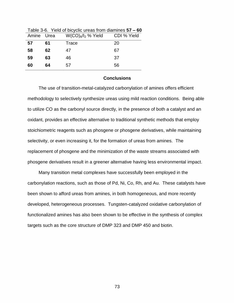
73
Table 3-6. Yield of bicyclic ureas from diamines 57 – 60
Amine Urea W(CO)6/I2 % Yield CDI % Yield
57 61 Trace 20
58 62 47 67
59 63 46 37
60 64 57 56
Conclusions
The use of transition-metal-catalyzed carbonylation of amines offers efficient
methodology to selectively synthesize ureas using mild reaction conditions. Being able
to utilize CO as the carbonyl source directly, in the presence of both a catalyst and an
oxidant, provides an effective alternative to traditional synthetic methods that employ
stoichiometric reagents such as phosgene or phosgene derivatives, while maintaining
selectivity, or even increasing it, for the formation of ureas from amines. The
replacement of phosgene and the minimization of the waste streams associated with
phosgene derivatives result in a greener alternative having less environmental impact.
Many transition metal complexes have successfully been employed in the
carbonylation reactions, such as those of Pd, Ni, Co, Rh, and Au. These catalysts have
been shown to afford ureas from amines, in both homogeneous, and more recently
developed, heterogeneous processes. Tungsten-catalyzed oxidative carbonylation of
functionalized amines has also been shown to be effective in the synthesis of complex
targets such as the core structure of DMP 323 and DMP 450 and biotin.
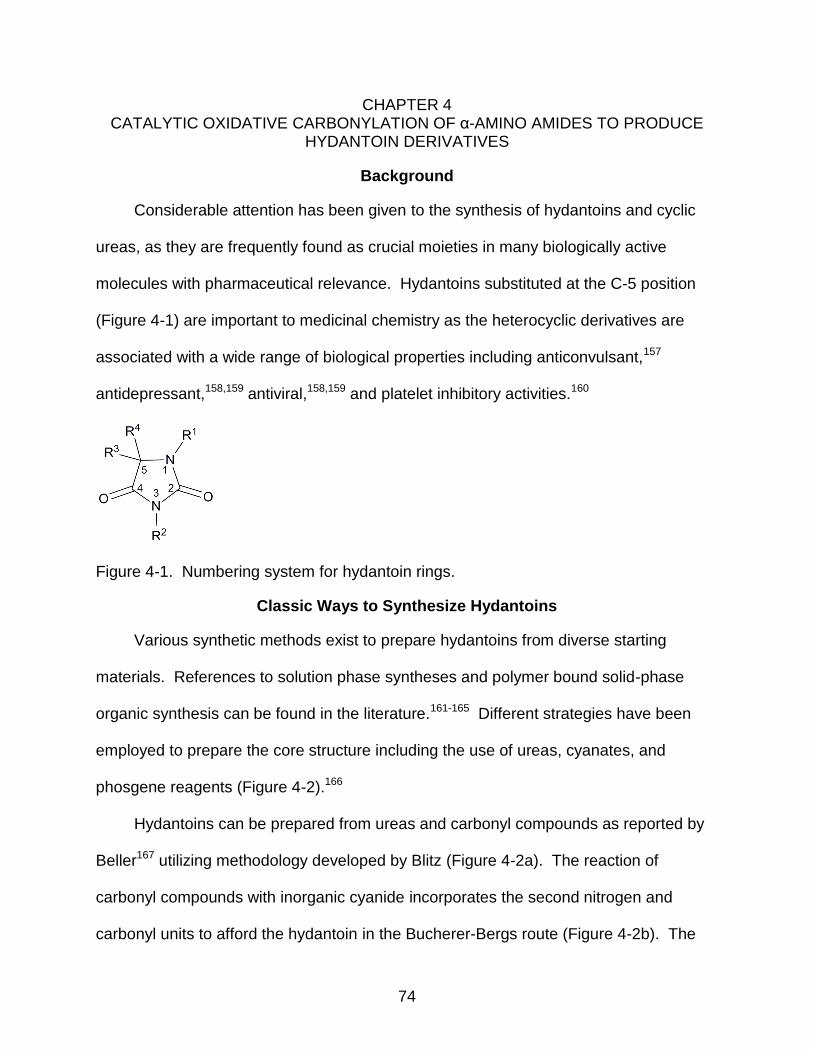
74
CHAPTER 4 CATALYTIC OXIDATIVE CARBONYLATION OF α-AMINO AMIDES TO PRODUCE
HYDANTOIN DERIVATIVES
Background
Considerable attention has been given to the synthesis of hydantoins and cyclic
ureas, as they are frequently found as crucial moieties in many biologically active
molecules with pharmaceutical relevance. Hydantoins substituted at the C-5 position
(Figure 4-1) are important to medicinal chemistry as the heterocyclic derivatives are
associated with a wide range of biological properties including anticonvulsant,157
antidepressant,158,159 antiviral,158,159 and platelet inhibitory activities.160
Figure 4-1. Numbering system for hydantoin rings.
Classic Ways to Synthesize Hydantoins
Various synthetic methods exist to prepare hydantoins from diverse starting
materials. References to solution phase syntheses and polymer bound solid-phase
organic synthesis can be found in the literature.161-165 Different strategies have been
employed to prepare the core structure including the use of ureas, cyanates, and
phosgene reagents (Figure 4-2).166
Hydantoins can be prepared from ureas and carbonyl compounds as reported by
Beller167 utilizing methodology developed by Blitz (Figure 4-2a). The reaction of
carbonyl compounds with inorganic cyanide incorporates the second nitrogen and
carbonyl units to afford the hydantoin in the Bucherer-Bergs route (Figure 4-2b). The
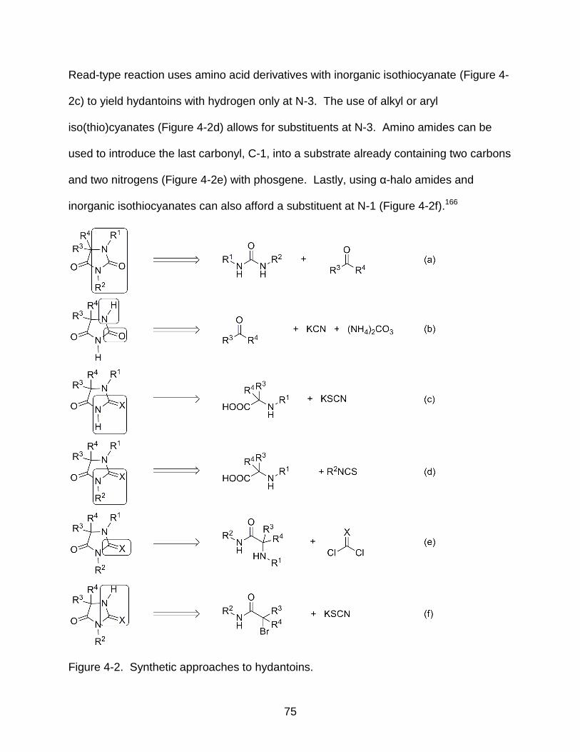
75
Read-type reaction uses amino acid derivatives with inorganic isothiocyanate (Figure 4-
2c) to yield hydantoins with hydrogen only at N-3. The use of alkyl or aryl
iso(thio)cyanates (Figure 4-2d) allows for substituents at N-3. Amino amides can be
used to introduce the last carbonyl, C-1, into a substrate already containing two carbons
and two nitrogens (Figure 4-2e) with phosgene. Lastly, using α-halo amides and
inorganic isothiocyanates can also afford a substituent at N-1 (Figure 4-2f).166
Figure 4-2. Synthetic approaches to hydantoins.
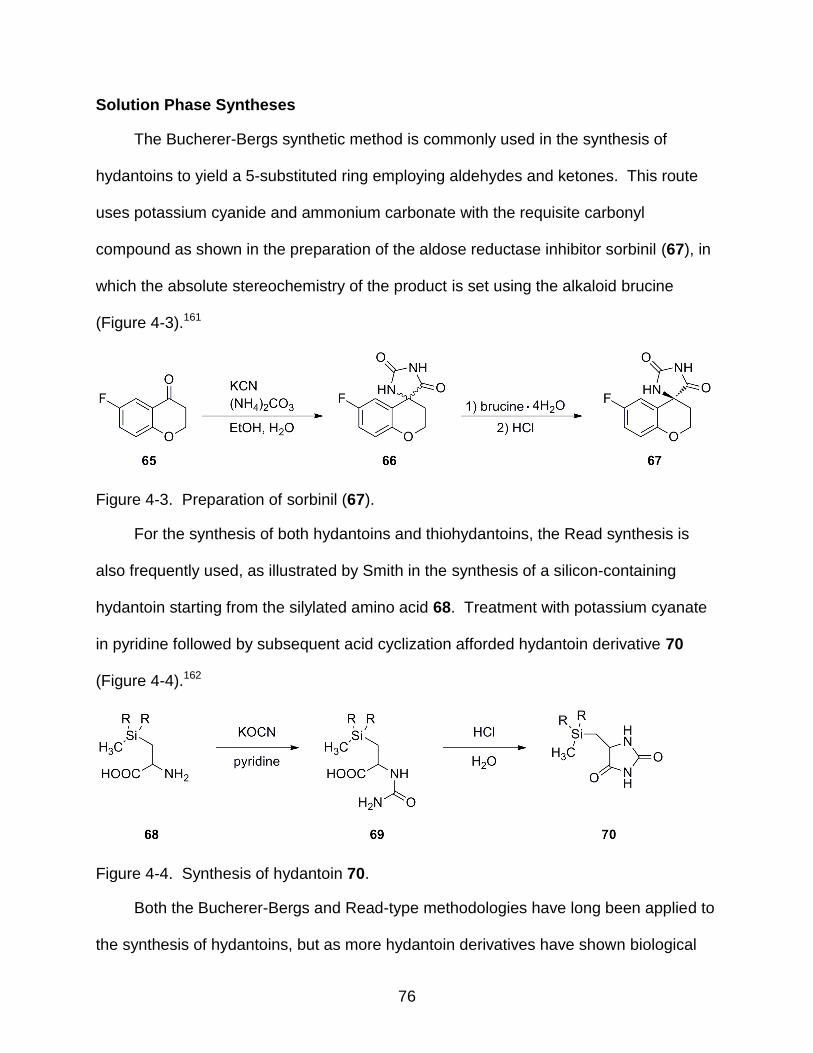
76
Solution Phase Syntheses
The Bucherer-Bergs synthetic method is commonly used in the synthesis of
hydantoins to yield a 5-substituted ring employing aldehydes and ketones. This route
uses potassium cyanide and ammonium carbonate with the requisite carbonyl
compound as shown in the preparation of the aldose reductase inhibitor sorbinil (67), in
which the absolute stereochemistry of the product is set using the alkaloid brucine
(Figure 4-3).161
Figure 4-3. Preparation of sorbinil (67).
For the synthesis of both hydantoins and thiohydantoins, the Read synthesis is
also frequently used, as illustrated by Smith in the synthesis of a silicon-containing
hydantoin starting from the silylated amino acid 68. Treatment with potassium cyanate
in pyridine followed by subsequent acid cyclization afforded hydantoin derivative 70
(Figure 4-4).162
Figure 4-4. Synthesis of hydantoin 70.
Both the Bucherer-Bergs and Read-type methodologies have long been applied to
the synthesis of hydantoins, but as more hydantoin derivatives have shown biological
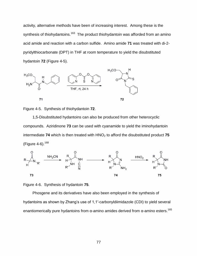
77
activity, alternative methods have been of increasing interest. Among these is the
synthesis of thiohydantoins.163 The product thiohydantoin was afforded from an amino
acid amide and reaction with a carbon sulfide. Amino amide 71 was treated with di-2-
pyridylthiocarbonate (DPT) in THF at room temperature to yield the disubstituted
hydantoin 72 (Figure 4-5).
Figure 4-5. Synthesis of thiohydantoin 72.
1,5-Disubstituted hydantoins can also be produced from other heterocyclic
compounds. Aziridinone 73 can be used with cyanamide to yield the iminohydantoin
intermediate 74 which is then treated with HNO2 to afford the disubstituted product 75
(Figure 4-6).168
Figure 4-6. Synthesis of hydantoin 75.
Phosgene and its derivatives have also been employed in the synthesis of
hydantoins as shown by Zhang’s use of 1,1′-carbonyldiimidazole (CDI) to yield several
enantiomerically pure hydantoins from α-amino amides derived from α-amino esters.165
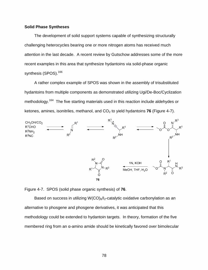
78
Solid Phase Syntheses
The development of solid support systems capable of synthesizing structurally
challenging heterocycles bearing one or more nitrogen atoms has received much
attention in the last decade. A recent review by Gutschow addresses some of the more
recent examples in this area that synthesize hydantoins via solid-phase organic
synthesis (SPOS).166
A rather complex example of SPOS was shown in the assembly of trisubstituted
hydantoins from multiple components as demonstrated utilizing Ugi/De-Boc/Cyclization
methodology.164 The five starting materials used in this reaction include aldehydes or
ketones, amines, isonitriles, methanol, and CO2 to yield hydantoins 76 (Figure 4-7).
Figure 4-7. SPOS (solid phase organic synthesis) of 76.
Based on success in utilizing W(CO)6/I2-catalytic oxidative carbonylation as an
alternative to phosgene and phosgene derivatives, it was anticipated that this
methodology could be extended to hydantoin targets. In theory, formation of the five
membered ring from an α-amino amide should be kinetically favored over bimolecular

79
acyclic urea formation. Therefore, the synthesis of a series of hydantoins was
undertaken to better understand the scope of the catalytic system.
A range of α-amino amides with differing substitution patterns was synthesized to
determine the effect upon cyclization using the W(CO)6/I2 system (Figure 4-8).
Figure 4-8. Proposed synthetic approach to using the W(CO6)/I2 system to yield hydantoins.
Synthesis of α-Amino Amides
Figure 4-9. Synthesis of α-amino amides 78-81.
Table 4-1. Synthesis of α-amino amides 78 – 81
Entry R Product
t
Yield
(%) 1 CH3 78 90
2 CH2CH3 79 82
3 CH(CH3)2 80 40
4 CH2Ph 81 45
A series of seven disubstituted α-amino amides containing various aromatic and
aliphatic side chains on either the amido or amino nitrogen was synthesized.
Compounds 78-81 were synthesized by treatment of the corresponding amino acid
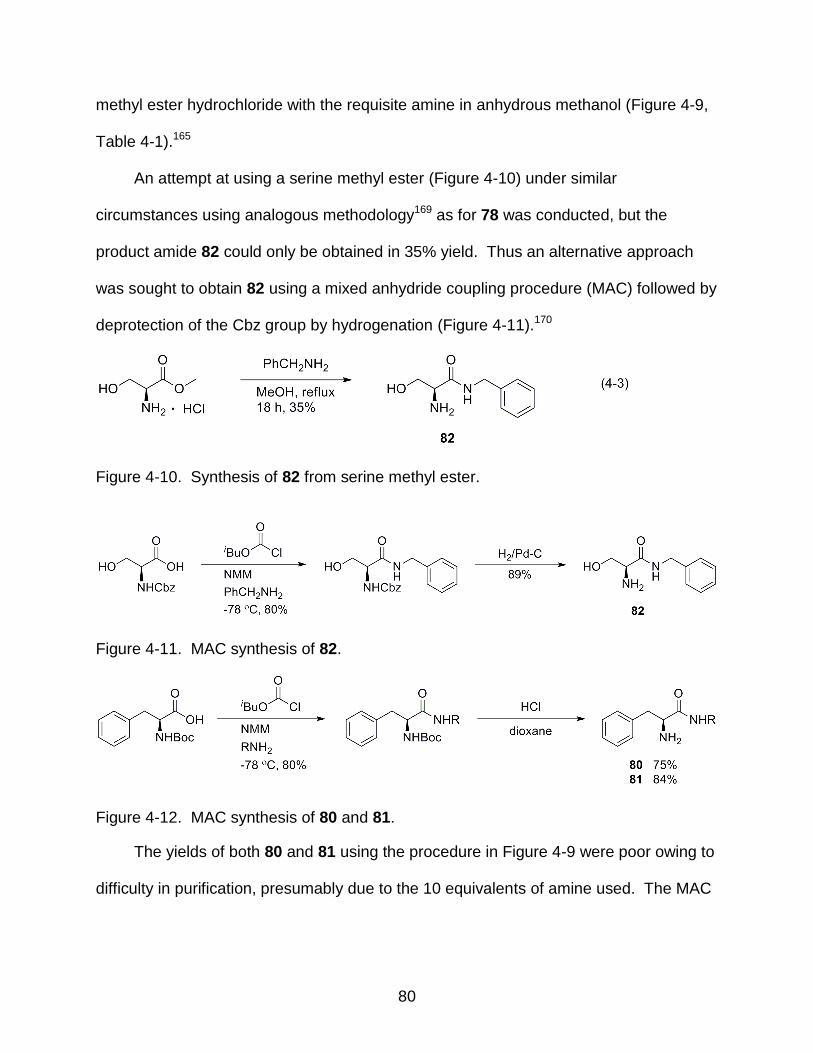
80
methyl ester hydrochloride with the requisite amine in anhydrous methanol (Figure 4-9,
Table 4-1).165
An attempt at using a serine methyl ester (Figure 4-10) under similar
circumstances using analogous methodology169 as for 78 was conducted, but the
product amide 82 could only be obtained in 35% yield. Thus an alternative approach
was sought to obtain 82 using a mixed anhydride coupling procedure (MAC) followed by
deprotection of the Cbz group by hydrogenation (Figure 4-11).170
Figure 4-10. Synthesis of 82 from serine methyl ester.
Figure 4-11. MAC synthesis of 82.
Figure 4-12. MAC synthesis of 80 and 81.
The yields of both 80 and 81 using the procedure in Figure 4-9 were poor owing to
difficulty in purification, presumably due to the 10 equivalents of amine used. The MAC
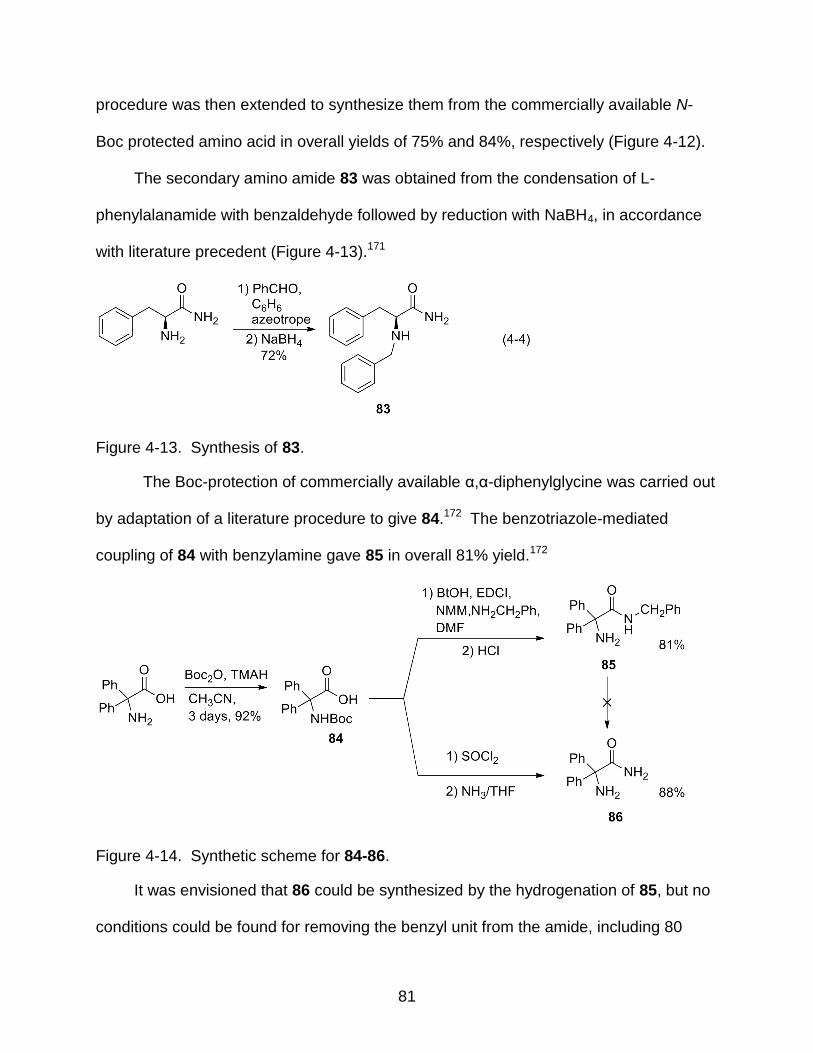
81
procedure was then extended to synthesize them from the commercially available N-
Boc protected amino acid in overall yields of 75% and 84%, respectively (Figure 4-12).
The secondary amino amide 83 was obtained from the condensation of L-
phenylalanamide with benzaldehyde followed by reduction with NaBH4, in accordance
with literature precedent (Figure 4-13).171
Figure 4-13. Synthesis of 83.
The Boc-protection of commercially available α,α-diphenylglycine was carried out
by adaptation of a literature procedure to give 84.172 The benzotriazole-mediated
coupling of 84 with benzylamine gave 85 in overall 81% yield.172
Figure 4-14. Synthetic scheme for 84-86.
It was envisioned that 86 could be synthesized by the hydrogenation of 85, but no
conditions could be found for removing the benzyl unit from the amide, including 80
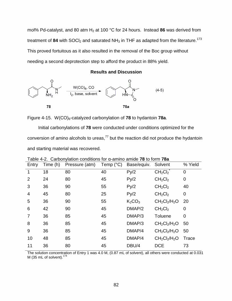
82
mol% Pd-catalyst, and 80 atm H2 at 100 °C for 24 hours. Instead 86 was derived from
treatment of 84 with SOCl2 and saturated NH3 in THF as adapted from the literature.173
This proved fortuitous as it also resulted in the removal of the Boc group without
needing a second deprotection step to afford the product in 88% yield.
Results and Discussion
Figure 4-15. W(CO)6-catalyzed carbonylation of 78 to hydantoin 78a.
Initial carbonylations of 78 were conducted under conditions optimized for the
conversion of amino alcohols to ureas,77 but the reaction did not produce the hydantoin
and starting material was recovered.
Table 4-2. Carbonylation conditions for α-amino amide 78 to form 78a
Entry Time (h) Pressure (atm) Temp (°C) Base/equiv. Solvent % Yield
1 18 80 40 Py/2 CH2Cl2* 0
2 24 80 45 Py/2 CH2Cl2 0
3 36 90 55 Py/2 CH2Cl2 40
4 45 80 25 Py/2 CH2Cl2 0
5 36 90 55 K2CO3 CH2Cl2/H2O 20
6 42 90 45 DMAP/2 CH2Cl2 0
7 36 85 45 DMAP/3 Toluene 0
8 36 85 45 DMAP/3 CH2Cl2/H2O 50
9 36 85 45 DMAP/4 CH2Cl2/H2O 50
10 48 85 45 DMAP/4 CH2Cl2/H2O Trace
11 36 80 45 DBU/4 DCE 73
The solution concentration of Entry 1 was 4.0 M, (0.87 mL of solvent), all others were conducted at 0.031 M (35 mL of solvent).
174
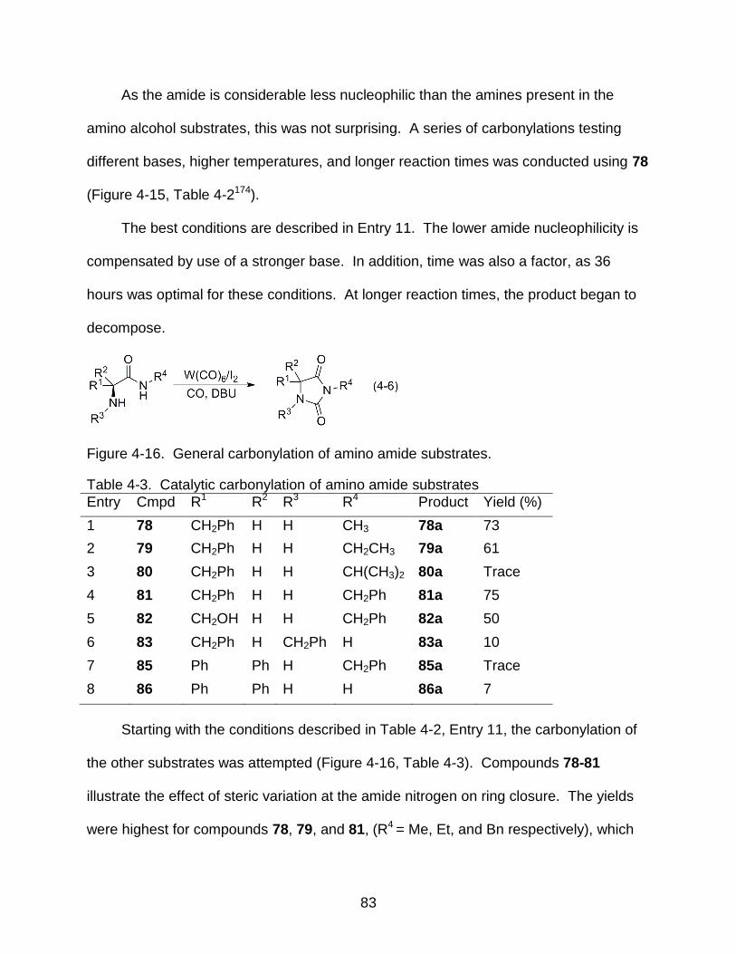
83
As the amide is considerable less nucleophilic than the amines present in the
amino alcohol substrates, this was not surprising. A series of carbonylations testing
different bases, higher temperatures, and longer reaction times was conducted using 78
(Figure 4-15, Table 4-2174).
The best conditions are described in Entry 11. The lower amide nucleophilicity is
compensated by use of a stronger base. In addition, time was also a factor, as 36
hours was optimal for these conditions. At longer reaction times, the product began to
decompose.
Figure 4-16. General carbonylation of amino amide substrates.
Table 4-3. Catalytic carbonylation of amino amide substrates
Entry Cmpd R1 R2 R3 R4 Product Yield (%)
1 78 CH2Ph H H CH3 78a 73
2 79 CH2Ph H H CH2CH3 79a 61
3 80 CH2Ph H H CH(CH3)2 80a Trace
4 81 CH2Ph H H CH2Ph 81a 75
5 82 CH2OH H H CH2Ph 82a 50
6 83 CH2Ph H CH2Ph H 83a 10
7 85 Ph Ph H CH2Ph 85a Trace
8 86 Ph Ph H H 86a 7
Starting with the conditions described in Table 4-2, Entry 11, the carbonylation of
the other substrates was attempted (Figure 4-16, Table 4-3). Compounds 78-81
illustrate the effect of steric variation at the amide nitrogen on ring closure. The yields
were highest for compounds 78, 79, and 81, (R4 = Me, Et, and Bn respectively), which

84
have no branching at the α-carbon of the substituent. The effect of the secondary alkyl
substituent is seen in 80 (R4 = iPr), where the hydantoin product 80a was only observed
in trace quantities. This is not surprising as similar effects have been found in the
carbonylation of secondary diamines containing these N-alkyl substituents.83,84 The
substrate with the free –OH group, 82, yielded the hydantoin product 82a in 50% yield
and no carbamate was observed. What was intriguing is that substrates 83, 85, and 86
yielded almost no product under these conditions. Since hydantoin 86a is the
anticonvulsant diphenylhydantoin (DilantinTM), and thus one of the more interesting
targets, other conditions for successful carbonylation of 86 were sought.
The results of the reaction conditions tested in the carbonylation of 86 to form
diphenylhydantoin 86a (Table 4-4) show the complexity of this system. Lack of
nucleophilicity rendered this substrate less reactive and stronger bases such as DABCO
(entry 4) and DBU (entry 7) were required. However, the excess base also could have
a deleterious effect upon the reaction as 1.1 equivalents of DBU (entry 8) gave 35%
yield and 2.2 equivalents DBU (entry 13) lowered the yield to 12%. Utilizing either
anhydrous solvent (entries 8 and 9) or high dilution (entry 12) also seemed to have no
effect upon yield. Anhydrous solvents were examined because one of the major
products was benzophenone, which presumably arises via hydrolysis, but the
decomposition occurred regardless of the presence of adventitious water in the solvent
or other reagents. Choice of solvent and temperature appeared to make the largest
impact upon the system. When using 1,2-dichloroethane (DCE) the reaction mixture
appeared often to undergo a coupling oligomerization as evidenced by a viscous dark
orange solution following carbonylation. When dichloromethane was substituted, the
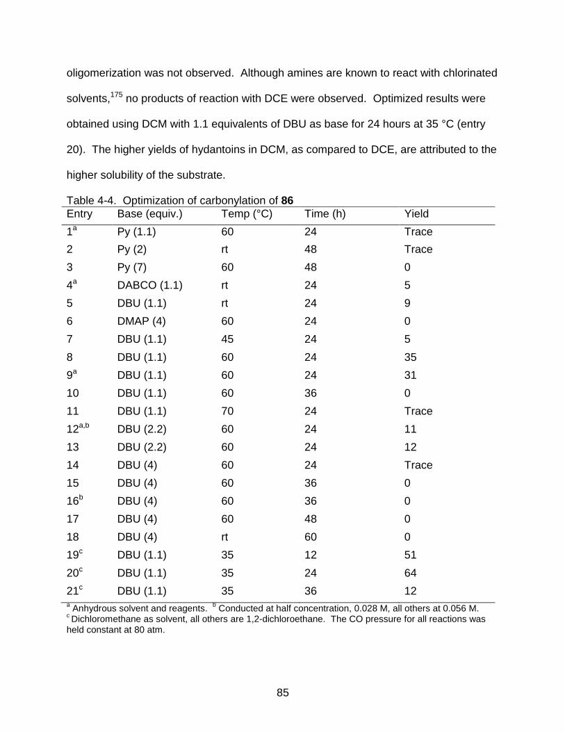
85
oligomerization was not observed. Although amines are known to react with chlorinated
solvents,175 no products of reaction with DCE were observed. Optimized results were
obtained using DCM with 1.1 equivalents of DBU as base for 24 hours at 35 °C (entry
20). The higher yields of hydantoins in DCM, as compared to DCE, are attributed to the
higher solubility of the substrate.
Table 4-4. Optimization of carbonylation of 86
Entry Base (equiv.) Temp (°C) Time (h) Yield
1a Py (1.1) 60 24 Trace
2 Py (2) rt 48 Trace
3 Py (7) 60 48 0
4a DABCO (1.1) rt 24 5
5 DBU (1.1) rt 24 9
6 DMAP (4) 60 24 0
7 DBU (1.1) 45 24 5
8 DBU (1.1) 60 24 35
9a DBU (1.1) 60 24 31
10 DBU (1.1) 60 36 0
11 DBU (1.1) 70 24 Trace
12a,b DBU (2.2) 60 24 11
13 DBU (2.2) 60 24 12
14 DBU (4) 60 24 Trace
15 DBU (4) 60 36 0
16b DBU (4) 60 36 0
17 DBU (4) 60 48 0
18 DBU (4) rt 60 0
19c DBU (1.1) 35 12 51
20c DBU (1.1) 35 24 64
21c DBU (1.1) 35 36 12 a Anhydrous solvent and reagents.
b Conducted at half concentration, 0.028 M, all others at 0.056 M.
c Dichloromethane as solvent, all others are 1,2-dichloroethane. The CO pressure for all reactions was
held constant at 80 atm.

86
Substrates 83 and 85 were then carbonylated using the optimized conditions for
86 (Eq. 4-6). The yields improved greatly over those obtained using the conditions
optimized for the methyl amide 78, but still are low to moderate (Table 4-5). Substrate
83, the constitutional isomer of 81, was only able to afford the hydantoin product in 41%
yield whereas 81a was obtained in 75%. This illustrates the effect that steric bulk on the
amine nitrogen has on the system. Compound 85 underwent competitive
decomposition to benzophenone during the formation of 85a, as was observed in
reactions of 86. It appears in the case of 85, the relative rate of decomposition into
benzophenone is faster than that of the relative rate of carbonylation. One possible
route to explain the low yields from 83a and 86a is that primary amides are less
nucleophilic than their secondary counterparts, and as a result the rate of carbonylation
is slower making decomposition pathways possible.
Table 4-5. Comparison of carbonylation conditions for 83, 85, 86
Substrate Hydantoin %Yielda %Yieldb
83 83a 10 41
85 85a Trace 11
86 86a 7 64 a Conditions optimized for 78a.
bConditions optimized for 86a.
When substrates 78-81 are carbonylated under the optimum conditions for
phenytoin, the yield of the corresponding hydantoins drops to less than 15% for all
amino amides. This could be due to differences in solubility of substrates in DCM
versus DCE, the fewer equivalents of base present, or that both reaction times and
temperatures were lower.
87
Conclusions
W(CO)6/I2 oxidative catalytic carbonylation of α-amino amides results in moderate-
to-good yields of hydantoins. Steric hindrance at the nitrogen in the substrate has an
effect on the yield and decomposition of the substrate is competitive with product
formation in a few cases. The use of this methodology provides an alternative to
previous existing synthetic pathways to hydantoins.
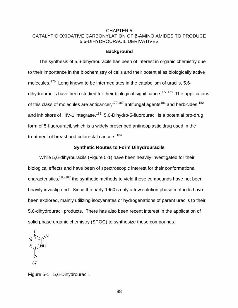
88
CHAPTER 5 CATALYTIC OXIDATIVE CARBONYLATION OF β-AMINO AMIDES TO PRODUCE
5,6-DIHYDROURACIL DERIVATIVES
Background
The synthesis of 5,6-dihydrouracils has been of interest in organic chemistry due
to their importance in the biochemistry of cells and their potential as biologically active
molecules.176 Long known to be intermediates in the catabolism of uracils, 5,6-
dihydrouracils have been studied for their biological significance.177,178 The applications
of this class of molecules are anticancer,179,180 antifungal agents181 and herbicides,182
and inhibitors of HIV-1 integrase.183 5,6-Dihydro-5-fluorouracil is a potential pro-drug
form of 5-fluorouracil, which is a widely prescribed antineoplastic drug used in the
treatment of breast and colorectal cancers.184
Synthetic Routes to Form Dihydrouracils
While 5,6-dihyrouracils (Figure 5-1) have been heavily investigated for their
biological effects and have been of spectroscopic interest for their conformational
characteristics,185-187 the synthetic methods to yield these compounds have not been
heavily investigated. Since the early 1950’s only a few solution phase methods have
been explored, mainly utilizing isocyanates or hydrogenations of parent uracils to their
5,6-dihydrouracil products. There has also been recent interest in the application of
solid phase organic chemistry (SPOC) to synthesize these compounds.
Figure 5-1. 5,6-Dihydrouracil.
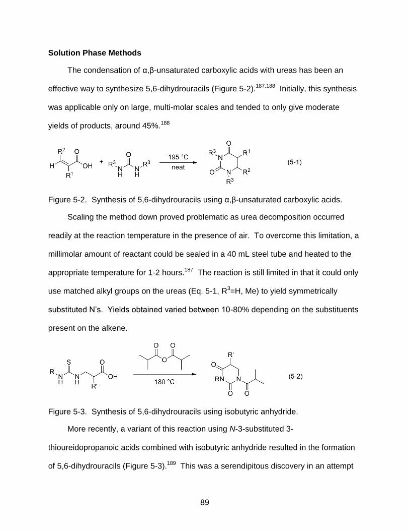
89
Solution Phase Methods
The condensation of α,β-unsaturated carboxylic acids with ureas has been an
effective way to synthesize 5,6-dihydrouracils (Figure 5-2).187,188 Initially, this synthesis
was applicable only on large, multi-molar scales and tended to only give moderate
yields of products, around 45%.188
Figure 5-2. Synthesis of 5,6-dihydrouracils using α,β-unsaturated carboxylic acids.
Scaling the method down proved problematic as urea decomposition occurred
readily at the reaction temperature in the presence of air. To overcome this limitation, a
millimolar amount of reactant could be sealed in a 40 mL steel tube and heated to the
appropriate temperature for 1-2 hours.187 The reaction is still limited in that it could only
use matched alkyl groups on the ureas (Eq. 5-1, R3=H, Me) to yield symmetrically
substituted N’s. Yields obtained varied between 10-80% depending on the substituents
present on the alkene.
Figure 5-3. Synthesis of 5,6-dihydrouracils using isobutyric anhydride.
More recently, a variant of this reaction using N-3-substituted 3-
thioureidopropanoic acids combined with isobutyric anhydride resulted in the formation
of 5,6-dihydrouracils (Figure 5-3).189 This was a serendipitous discovery in an attempt
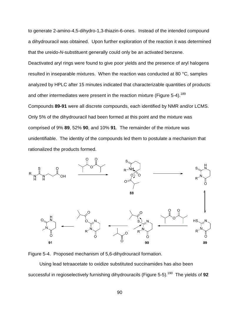
90
to generate 2-amino-4,5-dihydro-1,3-thiazin-6-ones. Instead of the intended compound
a dihydrouracil was obtained. Upon further exploration of the reaction it was determined
that the ureido-N-substituent generally could only be an activated benzene.
Deactivated aryl rings were found to give poor yields and the presence of aryl halogens
resulted in inseparable mixtures. When the reaction was conducted at 80 °C, samples
analyzed by HPLC after 15 minutes indicated that characterizable quantities of products
and other intermediates were present in the reaction mixture (Figure 5-4).189
Compounds 89-91 were all discrete compounds, each identified by NMR and/or LCMS.
Only 5% of the dihydrouracil had been formed at this point and the mixture was
comprised of 9% 89, 52% 90, and 10% 91. The remainder of the mixture was
unidentifiable. The identity of the compounds led them to postulate a mechanism that
rationalized the products formed.
Figure 5-4. Proposed mechanism of 5,6-dihydrouracil formation.
Using lead tetraacetate to oxidize substituted succinamides has also been
successful in regioselectively furnishing dihydrouracils (Figure 5-5).190 The yields of 92
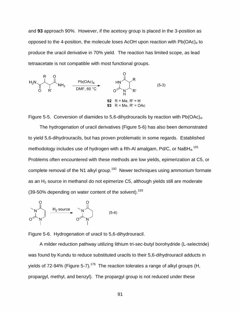
91
and 93 approach 90%. However, if the acetoxy group is placed in the 3-position as
opposed to the 4-position, the molecule loses AcOH upon reaction with Pb(OAc)4 to
produce the uracil derivative in 70% yield. The reaction has limited scope, as lead
tetraacetate is not compatible with most functional groups.
Figure 5-5. Conversion of diamides to 5,6-dihydrouracils by reaction with Pb(OAc)4.
The hydrogenation of uracil derivatives (Figure 5-6) has also been demonstrated
to yield 5,6-dihydrouracils, but has proven problematic in some regards. Established
methodology includes use of hydrogen with a Rh-Al amalgam, Pd/C, or NaBH4.191
Problems often encountered with these methods are low yields, epimerization at C5, or
complete removal of the N1 alkyl group.192 Newer techniques using ammonium formate
as an H2 source in methanol do not epimerize C5, although yields still are moderate
(39-50% depending on water content of the solvent).193
Figure 5-6. Hydrogenation of uracil to 5,6-dihydrouracil.
A milder reduction pathway utilizing lithium tri-sec-butyl borohydride (L-selectride)
was found by Kundu to reduce substituted uracils to their 5,6-dihydrouracil adducts in
yields of 72-94% (Figure 5-7).176 The reaction tolerates a range of alkyl groups (H,
propargyl, methyl, and benzyl). The propargyl group is not reduced under these
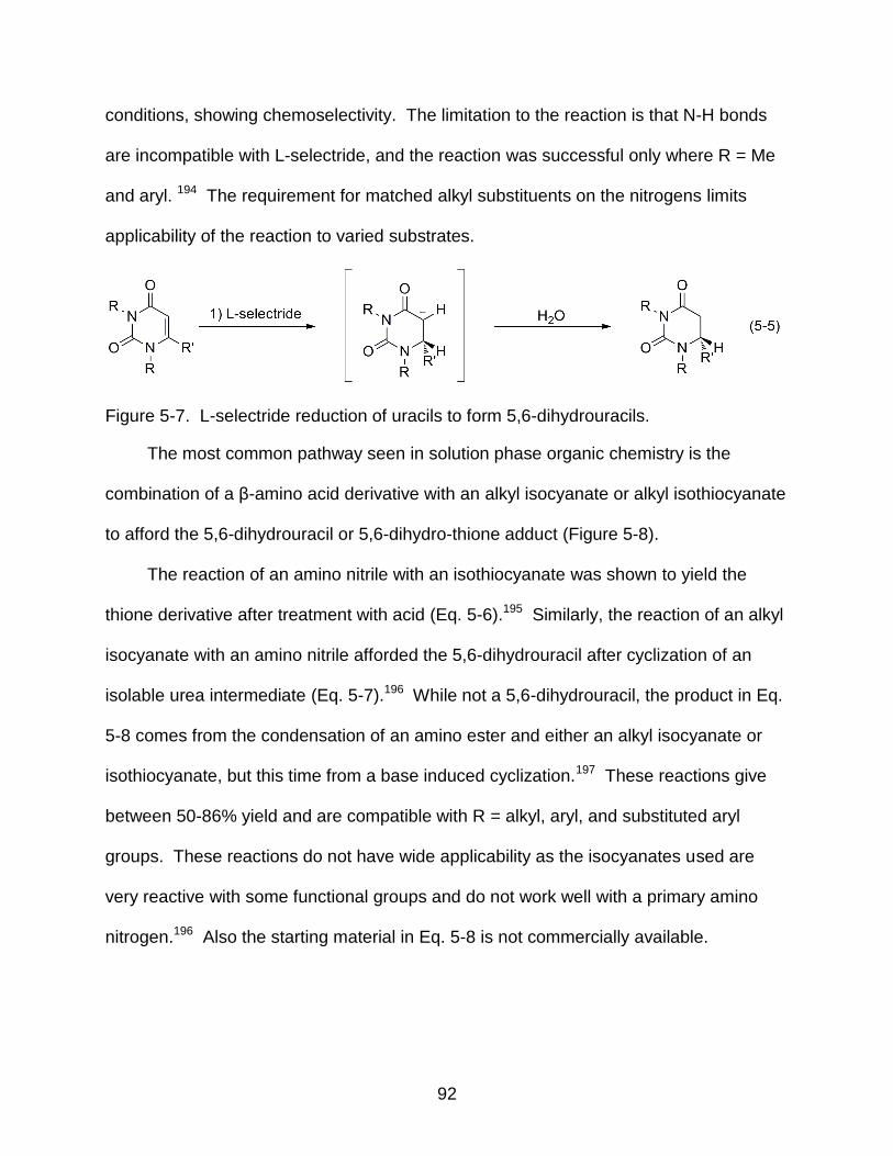
92
conditions, showing chemoselectivity. The limitation to the reaction is that N-H bonds
are incompatible with L-selectride, and the reaction was successful only where R = Me
and aryl. 194 The requirement for matched alkyl substituents on the nitrogens limits
applicability of the reaction to varied substrates.
Figure 5-7. L-selectride reduction of uracils to form 5,6-dihydrouracils.
The most common pathway seen in solution phase organic chemistry is the
combination of a β-amino acid derivative with an alkyl isocyanate or alkyl isothiocyanate
to afford the 5,6-dihydrouracil or 5,6-dihydro-thione adduct (Figure 5-8).
The reaction of an amino nitrile with an isothiocyanate was shown to yield the
thione derivative after treatment with acid (Eq. 5-6).195 Similarly, the reaction of an alkyl
isocyanate with an amino nitrile afforded the 5,6-dihydrouracil after cyclization of an
isolable urea intermediate (Eq. 5-7).196 While not a 5,6-dihydrouracil, the product in Eq.
5-8 comes from the condensation of an amino ester and either an alkyl isocyanate or
isothiocyanate, but this time from a base induced cyclization.197 These reactions give
between 50-86% yield and are compatible with R = alkyl, aryl, and substituted aryl
groups. These reactions do not have wide applicability as the isocyanates used are
very reactive with some functional groups and do not work well with a primary amino
nitrogen.196 Also the starting material in Eq. 5-8 is not commercially available.
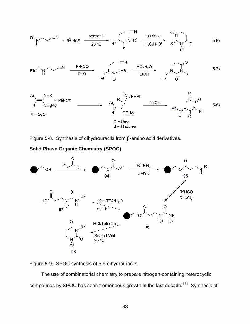
93
Figure 5-8. Synthesis of dihydrouracils from β-amino acid derivatives.
Solid Phase Organic Chemistry (SPOC)
Figure 5-9. SPOC synthesis of 5,6-dihydrouracils.
The use of combinatorial chemistry to prepare nitrogen-containing heterocyclic
compounds by SPOC has seen tremendous growth in the last decade.181 Synthesis of
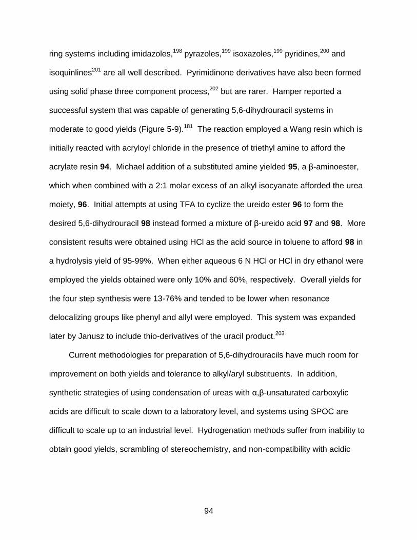
94
ring systems including imidazoles,198 pyrazoles,199 isoxazoles,199 pyridines,200 and
isoquinlines201 are all well described. Pyrimidinone derivatives have also been formed
using solid phase three component process,202 but are rarer. Hamper reported a
successful system that was capable of generating 5,6-dihydrouracil systems in
moderate to good yields (Figure 5-9).181 The reaction employed a Wang resin which is
initially reacted with acryloyl chloride in the presence of triethyl amine to afford the
acrylate resin 94. Michael addition of a substituted amine yielded 95, a β-aminoester,
which when combined with a 2:1 molar excess of an alkyl isocyanate afforded the urea
moiety, 96. Initial attempts at using TFA to cyclize the ureido ester 96 to form the
desired 5,6-dihydrouracil 98 instead formed a mixture of β-ureido acid 97 and 98. More
consistent results were obtained using HCl as the acid source in toluene to afford 98 in
a hydrolysis yield of 95-99%. When either aqueous 6 N HCl or HCl in dry ethanol were
employed the yields obtained were only 10% and 60%, respectively. Overall yields for
the four step synthesis were 13-76% and tended to be lower when resonance
delocalizing groups like phenyl and allyl were employed. This system was expanded
later by Janusz to include thio-derivatives of the uracil product.203
Current methodologies for preparation of 5,6-dihydrouracils have much room for
improvement on both yields and tolerance to alkyl/aryl substituents. In addition,
synthetic strategies of using condensation of ureas with α,β-unsaturated carboxylic
acids are difficult to scale down to a laboratory level, and systems using SPOC are
difficult to scale up to an industrial level. Hydrogenation methods suffer from inability to
obtain good yields, scrambling of stereochemistry, and non-compatibility with acidic
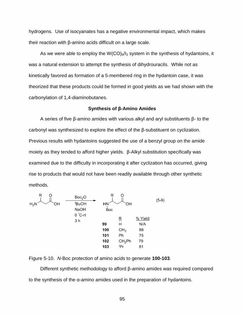
95
hydrogens. Use of isocyanates has a negative environmental impact, which makes
their reaction with β-amino acids difficult on a large scale.
As we were able to employ the W(CO)6/I2 system in the synthesis of hydantoins, it
was a natural extension to attempt the synthesis of dihydrouracils. While not as
kinetically favored as formation of a 5-membered ring in the hydantoin case, it was
theorized that these products could be formed in good yields as we had shown with the
carbonylation of 1,4-diaminobutanes.
Synthesis of β-Amino Amides
A series of five β-amino amides with various alkyl and aryl substituents β- to the
carbonyl was synthesized to explore the effect of the β-substituent on cyclization.
Previous results with hydantoins suggested the use of a benzyl group on the amide
moiety as they tended to afford higher yields. β-Alkyl substitution specifically was
examined due to the difficulty in incorporating it after cyclization has occurred, giving
rise to products that would not have been readily available through other synthetic
methods.
Figure 5-10. N-Boc protection of amino acids to generate 100-103.
Different synthetic methodology to afford β-amino amides was required compared
to the synthesis of the α-amino amides used in the preparation of hydantoins.
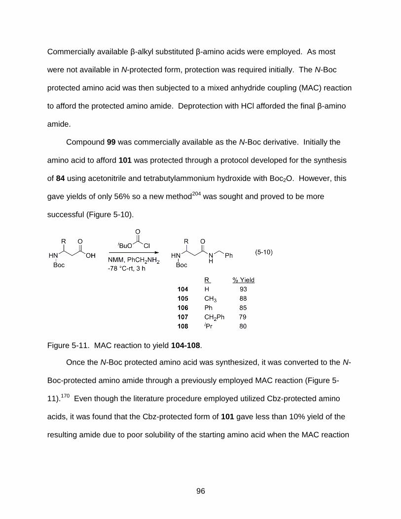
96
Commercially available β-alkyl substituted β-amino acids were employed. As most
were not available in N-protected form, protection was required initially. The N-Boc
protected amino acid was then subjected to a mixed anhydride coupling (MAC) reaction
to afford the protected amino amide. Deprotection with HCl afforded the final β-amino
amide.
Compound 99 was commercially available as the N-Boc derivative. Initially the
amino acid to afford 101 was protected through a protocol developed for the synthesis
of 84 using acetonitrile and tetrabutylammonium hydroxide with Boc2O. However, this
gave yields of only 56% so a new method204 was sought and proved to be more
successful (Figure 5-10).
Figure 5-11. MAC reaction to yield 104-108.
Once the N-Boc protected amino acid was synthesized, it was converted to the N-
Boc-protected amino amide through a previously employed MAC reaction (Figure 5-
11).170 Even though the literature procedure employed utilized Cbz-protected amino
acids, it was found that the Cbz-protected form of 101 gave less than 10% yield of the
resulting amide due to poor solubility of the starting amino acid when the MAC reaction
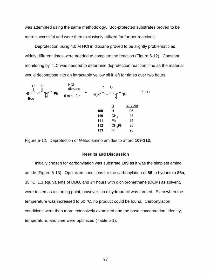
97
was attempted using the same methodology. Boc-protected substrates proved to be
more successful and were then exclusively utilized for further reactions.
Deprotection using 4.0 M HCl in dioxane proved to be slightly problematic as
widely different times were needed to complete the reaction (Figure 5-12). Constant
monitoring by TLC was needed to determine deprotection reaction time as the material
would decompose into an intractable yellow oil if left for times over two hours.
Figure 5-12. Deprotection of N-Boc amino amides to afford 109-113.
Results and Discussion
Initially chosen for carbonylation was substrate 109 as it was the simplest amino
amide (Figure 5-13). Optimized conditions for the carbonylation of 86 to hydantoin 86a,
35 °C, 1.1 equivalents of DBU, and 24 hours with dichloromethane (DCM) as solvent,
were tested as a starting point, however, no dihydrouracil was formed. Even when the
temperature was increased to 60 °C, no product could be found. Carbonylation
conditions were then more extensively examined and the base concentration, identity,
temperature, and time were optimized (Table 5-1).
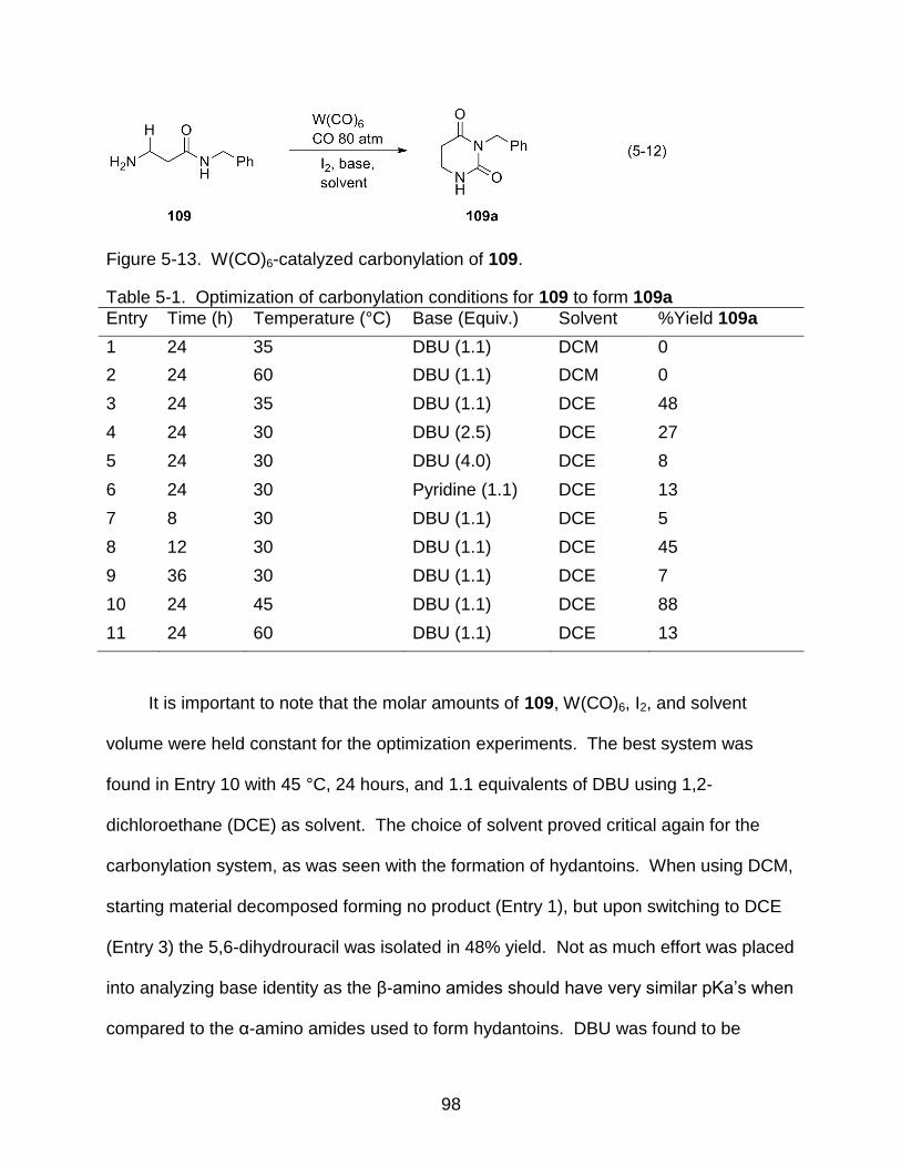
98
Figure 5-13. W(CO)6-catalyzed carbonylation of 109.
Table 5-1. Optimization of carbonylation conditions for 109 to form 109a
Entry Time (h) Temperature (°C) Base (Equiv.) Solvent %Yield 109a
1 24 35 DBU (1.1) DCM 0
2 24 60 DBU (1.1) DCM 0
3 24 35 DBU (1.1) DCE 48
4 24 30 DBU (2.5) DCE 27
5 24 30 DBU (4.0) DCE 8
6 24 30 Pyridine (1.1) DCE 13
7 8 30 DBU (1.1) DCE 5
8 12 30 DBU (1.1) DCE 45
9 36 30 DBU (1.1) DCE 7
10 24 45 DBU (1.1) DCE 88
11 24 60 DBU (1.1) DCE 13
It is important to note that the molar amounts of 109, W(CO)6, I2, and solvent
volume were held constant for the optimization experiments. The best system was
found in Entry 10 with 45 °C, 24 hours, and 1.1 equivalents of DBU using 1,2-
dichloroethane (DCE) as solvent. The choice of solvent proved critical again for the
carbonylation system, as was seen with the formation of hydantoins. When using DCM,
starting material decomposed forming no product (Entry 1), but upon switching to DCE
(Entry 3) the 5,6-dihydrouracil was isolated in 48% yield. Not as much effort was placed
into analyzing base identity as the β-amino amides should have very similar pKa’s when
compared to the α-amino amides used to form hydantoins. DBU was found to be

99
necessary for high yields, as when pyridine was used (Entry 6), the yield dropped
significantly. Longer reaction times were also found to decompose the product and the
optimum reaction time was determined to be 24 hours.
Product identification was based preliminarily on 1H and 13C NMR along with IR
data indicating a new carbonyl peak at 1726 cm-1. The new CO stretch is within the
range of reported values for 5,6-dihydrouracil compounds205 and the structure of 109a
was confirmed by comparison to literature data.206
Using the optimized conditions for 109 to form dihydrouracil 109a, the remaining β-
amino amides were carbonylated (Figure 5-14, Table 5-2). While 109 formed the
corresponding dihydrouracil in good yield, the β-alkyl substituted substrates resulted in
acyclic urea formation. New CO stretches were found around 1640 cm-1 in the IR data
to corroborate this conclusion. These new CO stretches are sharply lower than
reported values for 5,6-dihydrouracil by 80 cm-1 and are consistent with those reported
for acyclic ureas.70,205 Structure confirmation was obtained from MS data (vide infra).
Figure 5-14. Carbonylation of substrates 110-113 to form 110a – 113a using optimized conditions from 109a.
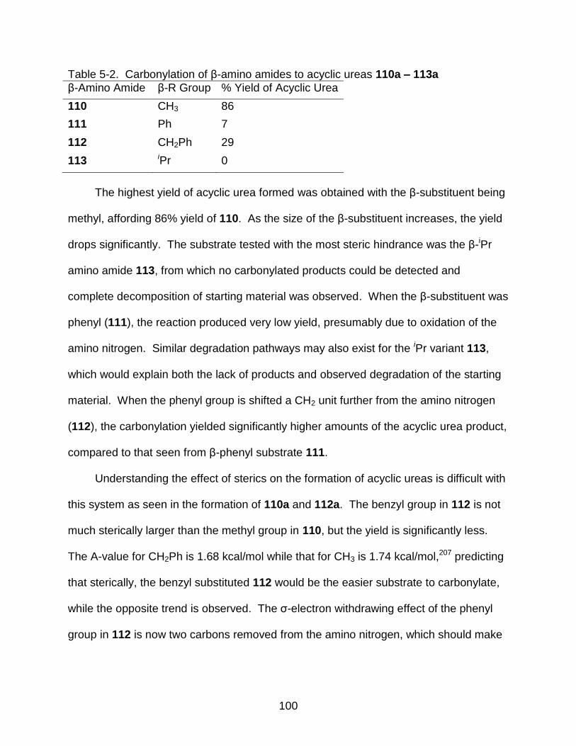
100
Table 5-2. Carbonylation of β-amino amides to acyclic ureas 110a – 113a
β-Amino Amide β-R Group % Yield of Acyclic Urea
110 CH3 86
111 Ph 7
112 CH2Ph 29
113 iPr 0
The highest yield of acyclic urea formed was obtained with the β-substituent being
methyl, affording 86% yield of 110. As the size of the β-substituent increases, the yield
drops significantly. The substrate tested with the most steric hindrance was the β-iPr
amino amide 113, from which no carbonylated products could be detected and
complete decomposition of starting material was observed. When the β-substituent was
phenyl (111), the reaction produced very low yield, presumably due to oxidation of the
amino nitrogen. Similar degradation pathways may also exist for the iPr variant 113,
which would explain both the lack of products and observed degradation of the starting
material. When the phenyl group is shifted a CH2 unit further from the amino nitrogen
(112), the carbonylation yielded significantly higher amounts of the acyclic urea product,
compared to that seen from β-phenyl substrate 111.
Understanding the effect of sterics on the formation of acyclic ureas is difficult with
this system as seen in the formation of 110a and 112a. The benzyl group in 112 is not
much sterically larger than the methyl group in 110, but the yield is significantly less.
The A-value for CH2Ph is 1.68 kcal/mol while that for CH3 is 1.74 kcal/mol,207 predicting
that sterically, the benzyl substituted 112 would be the easier substrate to carbonylate,
while the opposite trend is observed. The σ-electron withdrawing effect of the phenyl
group in 112 is now two carbons removed from the amino nitrogen, which should make

101
the nucleophilicity of the amino nitrogens approximately the same in 112 and 100. The
interplay between sterics and electronics of this system is very complex.
An attempt to carbonylate substrate 110 under high dilution conditions was also
examined with a substrate concentration of 0.0028 M (compared to 0.028 M for
optimized conversion of 109 to 109a and 0.055 M used in the formation of 86a) in DCE.
After the 24 hour reaction time, only complete degradation of the starting material was
observed. Neither acyclic urea nor 5,6-dihydrouracil formation was detected in the
reaction mixture.
A direct comparison of product ratios is available between substrates 81 and 111
as they are constitutional isomers. Hydantoin 81a forms in 75% yield from the
carbonylation of 81, whereas 111 forms the acyclic urea in only 7%. It appears that the
relative rate of cyclization is significantly faster for the formation of the five-membered
hydantoin ring over the relative rate of formation for the acyclic urea. In the case of
formation of 5,6-dihydrouracils, the opposite trend is seen. While not surprising that the
relative rate of five-membered ring formation is faster than that of the six-, it is
interesting that even a small β-alkyl substituent, like a methyl group, can slow down the
relative rate of cyclization enough to favor acyclic urea formation over cyclization of the
dihydrouracil. This was demonstrated in the ability of 109 to carbonylate to form 5,6-
dihydrouracil 109a in 88% yield, while as β-methyl substituted 110 only forms the
acyclic urea.
Conclusions
The oxidative carbonylation of β-amino amides using the W(CO)6/I2 system has
only proven effective to form 5,6-dihydrouracil 109a, which has no β-alkyl substituent.
When alkyl substituents are added in the β-position, the carbonylation of the amino

102
amide affords acyclic urea preferentially over formation of the 5,6-dihydrouracil. The
interplay between sterics and electronics brought about by the β-alkyl substituent is not
fully understood, but has a large effect upon the yields of acyclic ureas. This
methodology provides a synthetic route to form 5,6-dihydrouracils, although it is limited
in scope.
103
CHAPTER 6 EXPERIMENTAL SECTION
Synthesis of Alkylzirconium Complexes
General
All manipulations were carried out using standard Schlenk and glove box
techniques under an inert atmosphere of argon or nitrogen. All solvents, unless
otherwise noted, were purchased from Fisher and passed through an M. Braun MB-SP
solvent purification system or were distilled from sodium/benzophenone prior to use.
All 1H and 13C NMR spectra were obtained on a VXR 300 MHz spectrometer.
Mass spectrometry services were provided by the University of Florida analytical
service.
Synthesis of ZrNpxCly Complexes
Neopentylmagnesium chloride
A mixture of 9.00 mL (73.0 mmol) freshly distilled neopentyl chloride and 1.21 mL
(14.0 mmol) 1,2-dibromoethane were placed in an addition funnel and added dropwise
to a three-neck Schlenk flask containing 3.65 g (151 mmol) activated Mg turnings and
50 mL ether over a 1 hour period, in accordance with literature procedure.42 The
resulting mixture was refluxed overnight and filtered through a 1 cm pad of Celite
(previously dried and evacuated) to afford a pale yellow product. Yield: 57 mL of 1.0 M
solution, 78%. 1H NMR (C6D6) δ 0.890 (s, 9 H), 1.18 (s, 2H).42
Tetraneopentylzirconium (2)
Neopentylmagnesium chloride concentration was determined208 and 8.1 mL of
1.0 M (8.1 mmol) of the Grignard reagent in ether was measured into an addition funnel

104
and added dropwise to a three-neck Schlenk flask containing 0.629 g (2.70 mmol) ZrCl4
slurried in 60 mL ether at 0 °C over a 1 hour period. The mixture was then allowed to
warm to room temperature and stirred vigorously overnight. Volatiles were then
removed via reduced pressure and the resulting brown solid was extracted with
hexanes and filtered through a 1 cm Celite pad (previously dried and evacuated).
Volatiles were removed again to leave a pale-brown solid which was sublimed (75 °C,
0.02 mmHg) to produce ZrNp4 as a white solid. Yield 0.523 g, 70%. The product was
identified based on literature values.42 1H NMR (C6D6) δ 1.15 (s, 9H), 1.55 (s, 2H)
Trisneopentyl zirconium monochloride (10)
A three-neck Schlenk flask with 0.721 g (1.92 mmol) of 2 was dissolved in 40 mL
ether and added at 0 °C to 0.149 g (0.640 mmol) ZrCl4 dropwise over a one hour period.
The reaction temperature was maintained at 0 °C overnight and resulted in a bright
yellow solution. Volatiles were then removed leaving a bright yellow solid. The solid
was then stored at -30 °C in the dark. Yield 0.755 g, 87%. Decomposition can be seen
at room temperature by darkening of the product. The product was identified based on
literature values.43 1H NMR (C6D6) δ 1.15 (s, 9H), 1.55 (s, 2H).
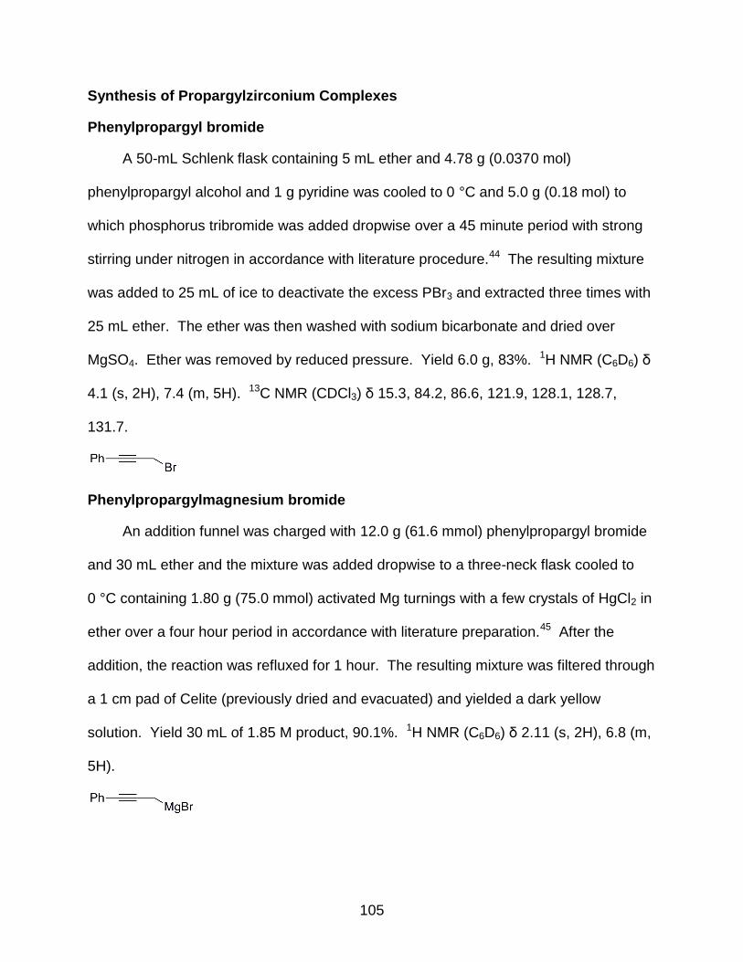
105
Synthesis of Propargylzirconium Complexes
Phenylpropargyl bromide
A 50-mL Schlenk flask containing 5 mL ether and 4.78 g (0.0370 mol)
phenylpropargyl alcohol and 1 g pyridine was cooled to 0 °C and 5.0 g (0.18 mol) to
which phosphorus tribromide was added dropwise over a 45 minute period with strong
stirring under nitrogen in accordance with literature procedure.44 The resulting mixture
was added to 25 mL of ice to deactivate the excess PBr3 and extracted three times with
25 mL ether. The ether was then washed with sodium bicarbonate and dried over
MgSO4. Ether was removed by reduced pressure. Yield 6.0 g, 83%. 1H NMR (C6D6) δ
4.1 (s, 2H), 7.4 (m, 5H). 13C NMR (CDCl3) δ 15.3, 84.2, 86.6, 121.9, 128.1, 128.7,
131.7.
Phenylpropargylmagnesium bromide
An addition funnel was charged with 12.0 g (61.6 mmol) phenylpropargyl bromide
and 30 mL ether and the mixture was added dropwise to a three-neck flask cooled to
0 °C containing 1.80 g (75.0 mmol) activated Mg turnings with a few crystals of HgCl2 in
ether over a four hour period in accordance with literature preparation.45 After the
addition, the reaction was refluxed for 1 hour. The resulting mixture was filtered through
a 1 cm pad of Celite (previously dried and evacuated) and yielded a dark yellow
solution. Yield 30 mL of 1.85 M product, 90.1%. 1H NMR (C6D6) δ 2.11 (s, 2H), 6.8 (m,
5H).

106
Tetra-η3(phenylpropargyl) zirconium (11)
An addition funnel was charged with 20.0 mL of 1.85 M
phenylpropargylmagnesium bromide (37.0 mmol) and added dropwise to a three-neck
flask containing 2.16 g (9.25 mmol) ZrCl4 slurried in 100 mL ether over a one hour
period and stirred overnight at room temperature. Volatiles were removed via reduced
pressure and a brown solid remained. The solid was extracted with 150 mL toluene and
filtered through a fine glass frit. The filtrate was then condensed and crystallized with
hexanes. The recrystallized product was tan in color and was subjected to repeated
vapor diffusion recrystallization using THF and pentanes until a colorless-to-white solid
remained. Yield 3.77 g, 74%. 1H NMR (C6D5CD3) δ 3.22 (s, 2H), 6.95 (m, 5H).
Structure determination for 11
X-ray experimental data for 11 were collected at 173 K on a Siemens SMART
PLATFORM equipped with A CCD area detector and a graphite monochromator
utilizing MoK radiation (λ = 0.71073 Å). Cell parameters were refined using up to 8192
reflections. A full sphere of data (1850 frames) was collected using the ω-scan method
(0.3° frame width). The first 50 frames were re-measured at the end of data collection
to monitor instrument and crystal stability (maximum correction on I was < 1 %).
Absorption corrections by integration were applied based on measured indexed crystal
faces.
The structure was solved by the Direct Methods in SHELXTL6,209 and refined
using full-matrix least squares. The non-H atoms were treated anisotropically, whereas

107
the hydrogen atoms were calculated in ideal positions and were riding on their
respective carbon atoms. The complexes are located on 2-fold rotation axes; thus a
half complex occupies the asymmetric unit. A total of 168 parameters were refined in
the final cycle of refinement using 2730 reflections with I > 2σ(I) to yield R1 and wR2 of
2.44% and 6.76%, respectively. Refinement was done using F2.
Computational Analysis of 11
Geometry optimizations and single-point calculations were performed using the
DFT B3LYP functional and the LANL2DZ basis set utilized in the Gaussian 03210
program package.55-58 Compositions of molecular orbitals were calculated using the
AOMix program.211,212 Molecular orbital pictures were generated from Gabedit.
Computational resources and support were provided by the University of Florida High-
Performance Computing Center.
Methylpropargylmagnesium bromide
An addition funnel was charged with 6.61 mL (75.5 mmol) freshly distilled 1-
bromo-2-butyne was diluted with 20 mL ether and added dropwise to a three-neck flask
containing a 20 mL ether suspension of 2.02 g (83.1 mmol) activated Mg turnings and a
few crystals of HgCl2 cooled to 0 °C over a 1 hour period. After addition, the reaction
was allowed to warm to room temperature and stirred overnight. The resulting cloudy
green-yellow solution was filtered through a 1 cm pad of Celite (previously dried and
evacuated) and yielded a bright yellow solution. Yielded 50 mL of a 0.792 M solution,
overall 83.6%. 1H NMR (C6D6) δ 1.68 (t, 3H) 1.8 (q, 2H)

108
(Methylpropargyl)nzirconium (12)
An addition funnel was charged with 20.0 mL of 0.792 (15.8 mmol)
methylpropargylmagnesium bromide was added dropwise to a flask containing 0.923 g
(3.95 mmol) ZrCl4 slurried in 100 mL ether over a 1 hour period. The mixture was then
stirred overnight at room temperature. Volatiles were removed by reduced pressure
and the resulting brown solid was extracted with 150 mL toluene. The extract was then
filtered through a fine glass frit and condensed and recrystallized with hexanes. The
resulting air and moisture sensitive brown solid showed a myriad of peaks in the 1H-
NMR spectrum and was unable to be further purified.
Synthesis of α- and β-Amino Amides for Oxidative Carbonylation
General Procedures
All experiments, unless otherwise noted, were carried out under an inert argon
atmosphere with oven dried glassware. Solvents for carbonylation reactions were
passed through a solvent purification system (vide supra) prior to use or were distilled
from CaH2. Commercially available substrates were used without further purification.
All column chromatography was conducted with 270-400 mesh silica. All 1H and 13C
NMR spectra were obtained on a Varian Gemini 300 MHz, VXR 300 MHz, or Mercury
300 MHz spectrometer. Infrared spectra were recorded on a Perkin-Elmer 1600 FT-IR.
High-resolution mass spectrometry was performed by the University of Florida analytical
service.

109
General Procedure for the Synthesis of α-Amino Amides 78-82
The amino acid methyl ester hydrochloride (4.0 mmol) and the alkylamine (40
mmol) were dissolved in anhydrous methanol (20 mL) and stirred at room temperature
for 3 days, in accordance with literature protocol.165 The reaction mixture was
concentrated, and the residue was purified by column chromatography using
EtOAc/MeOH (96:4) as eluant affording the α-amino amides 78-82 in yields reported in
Table 4-1. Product identification was made from literature comparison.165,170
(S)-2-Amino-N-methyl-3-phenylpropionamide (78)
1H NMR (CDCl3) δ 1.35 (broad s, 2H, NH2), 2.67 (dd, 1H, CH2CHCO), 2.84 (d, 3H,
NHCH3), 3.48 (d, 2H, PhCH2), 7.22-7.30 (m, 5H, C6H5).
(S)-2-Amino-N-ethyl-3-phenylpropionamide (79)
1H NMR (CDCl3) δ 1.56 (broad s, 2H, NH2), 2.65 (t, 3H, NHCH2CH3), 2.71 (dd, 1H,
CH2CHCO), 3.31 (m, 2H, NCH2CH3), 3.64 (d, 2H, PhCH2CH), 7.25-7.34 (m, 5H, C6H5).
(S)-2-Amino-N-isopropyl-3-phenylpropionamide (80)
1H NMR (CDCl3) δ 1.52 (broad s, 2H, NH2), 2.43 (d, 6H, NHCH(CH3)2), 2.59 (dd,
1H, CH2CHCO), 3.17 (m, 1H, NCH(CH3)2), 3.46 (d, 2H, PhCH2CH), 7.21-7.30 (m, 5H,
C6H5).
110
(S)-2-Amino-N-benzyl-3-phenylpropionamide (81)
1H NMR (CDCl3) δ 1.46 (broad s, 2H, NH2), 2.72 (dd, 1H, CH2CHCO), 3.37 (d, 2H,
PhCH2CH), 3.51 (d, 2H, NHCH2Ph), 7.25-7.38 (m, 10H, aromatics).
General Preparation of α-Amino Amide 82 by MAC
A two step procedure, as described in the literature,170 was followed starting with
commercially available Cbz-serine. A 25 mL solution of dry THF containing
carbobenzyloxy-DL-serine (2.00 g, 8.40 mmol) was cooled to -78 °C and then 4-
methylmorpholine (1.29 g, 10.5 mmol) was added and stirred for 5 minutes. Isobutyl
chloroformate (1.46 g, 10.5 mmol) was then added and the reaction mixture was strirred
for 15 minutes after which benzylamine (1.08 g, 10.5 mmol) was added. The reaction
was then stirred for 15 minutes at -78 °C, before allowing to warm to room temperature
where it continued to stir for one hour. The reaction mixture was filtered and the filtrate
evaporated by reduced pressure. The concentrated residue was suspended in ether
(75 mL) and filtered again. The crude product was purified by column chromatography
with 5% MeOH/DCM eluent. A 1.95 g amount of product was isolated, a 74% yield.
The hydrogenation of the Cbz-protecting group was then accomplished. A flask
containing 1.71 g (5.44 mmol) amount of the purified benzamide (vide supra) was
combined with 0.286 g of Pd/C (10% w/w) and slurried in 50 mL anhydrous MeOH. The
reaction was stirred under an atmosphere of H2 for 3 hours after which the mixture was
filtered through a 2 cm pad of Celite. The filtrate was condensed by reduced pressure.
The crude residue was purified by column chromatography using 7.5% MeOH/DCM as
eluent affording 0.951 g of 82 in a yield of 90%. The product was identified by
comparison to literature values.170 1H NMR (DMSO) δ 1.90 (broad s, 2H, NH2), 3.23 (t,
1H, CH2CHCO), 3.41 (m, 2H, CH2OH), 4.25 (d, 2H, NHCH2Ph), 4.76 (broad s, 1H, OH),

111
7.18-7.31(m, 5H, C6H5), 8.36 (broad s, 1H, NH). Substrates 80 and 81 were also
alternatively made using this synthetic protocol.
Synthesis of α-Amino Amide 83
According to the literature171 L-Phenylalanamide (3.05 mmol) and benzaldehyde
(3.05 mmol) were dissolved in 40 mL anhydrous benzene in a round bottom flask
equipped with a Dean-Stark trap and condenser. The mixture was then refluxed for 3
hours and the benzene/water azeotrope was removed as needed. Solvent was then
removed via reduced pressure and replaced with 20 mL MeOH to which 1.10 mmol of
NaBH4 was added and stirred for 1 hour. Solvent was removed and the resulting solid
was triturated in hexanes to afford an oily solid. Column chromatography with 95/5
(DCM:MeOH) was then used to complete the purification. The product was obtained in
72% yield and was identified by comparison to literature values.171 1H NMR (CDCl3) δ
1.77 (broad s, 1H, NH), 2.78 (t, 1H, CH2CHCO), 3.34 (dd, 2H, PhCH2CH), 3.65 (dd, 2H,
PhCH2NH), 5.83 (broad s, 2H, CONH2), 7.10-7.31 (m, 10H, aromatics).
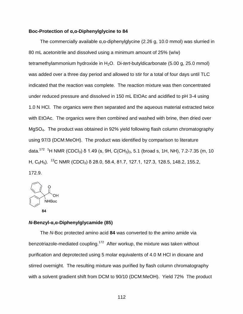
112
Boc-Protection of α,α-Diphenylglycine to 84
The commercially available α,α-diphenylglycine (2.26 g, 10.0 mmol) was slurried in
80 mL acetonitrile and dissolved using a minimum amount of 25% (w/w)
tetramethylammonium hydroxide in H2O. Di-tert-butyldicarbonate (5.00 g, 25.0 mmol)
was added over a three day period and allowed to stir for a total of four days until TLC
indicated that the reaction was complete. The reaction mixture was then concentrated
under reduced pressure and dissolved in 150 mL EtOAc and acidified to pH 3-4 using
1.0 N HCl. The organics were then separated and the aqueous material extracted twice
with EtOAc. The organics were then combined and washed with brine, then dried over
MgSO4. The product was obtained in 92% yield following flash column chromatography
using 97/3 (DCM:MeOH). The product was identified by comparison to literature
data.172 1H NMR (CDCl3) δ 1.49 (s, 9H, C(CH3)3, 5.1 (broad s, 1H, NH), 7.2-7.35 (m, 10
H, C6H5). 13C NMR (CDCl3) δ 28.0, 58.4, 81.7, 127.1, 127.3, 128.5, 148.2, 155.2,
172.9.
N-Benzyl-α,α-Diphenylglycamide (85)
The N-Boc protected amino acid 84 was converted to the amino amide via
benzotriazole-mediated coupling.172 After workup, the mixture was taken without
purification and deprotected using 5 molar equivalents of 4.0 M HCl in dioxane and
stirred overnight. The resulting mixture was purified by flash column chromatography
with a solvent gradient shift from DCM to 90/10 (DCM:MeOH). Yield 72% The product
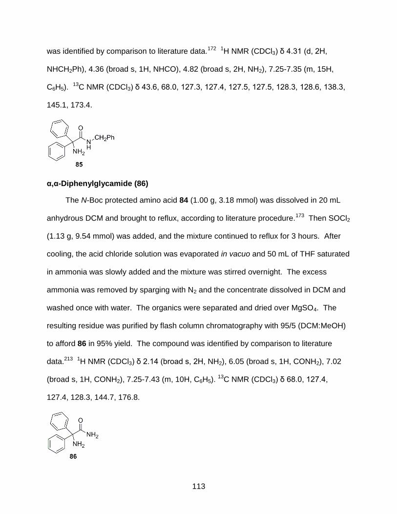
113
was identified by comparison to literature data.172 1H NMR (CDCl3) δ 4.31 (d, 2H,
NHCH2Ph), 4.36 (broad s, 1H, NHCO), 4.82 (broad s, 2H, NH2), 7.25-7.35 (m, 15H,
C6H5). 13C NMR (CDCl3) δ 43.6, 68.0, 127.3, 127.4, 127.5, 127.5, 128.3, 128.6, 138.3,
145.1, 173.4.
α,α-Diphenylglycamide (86)
The N-Boc protected amino acid 84 (1.00 g, 3.18 mmol) was dissolved in 20 mL
anhydrous DCM and brought to reflux, according to literature procedure.173 Then SOCl2
(1.13 g, 9.54 mmol) was added, and the mixture continued to reflux for 3 hours. After
cooling, the acid chloride solution was evaporated in vacuo and 50 mL of THF saturated
in ammonia was slowly added and the mixture was stirred overnight. The excess
ammonia was removed by sparging with N2 and the concentrate dissolved in DCM and
washed once with water. The organics were separated and dried over MgSO4. The
resulting residue was purified by flash column chromatography with 95/5 (DCM:MeOH)
to afford 86 in 95% yield. The compound was identified by comparison to literature
data.213 1H NMR (CDCl3) δ 2.14 (broad s, 2H, NH2), 6.05 (broad s, 1H, CONH2), 7.02
(broad s, 1H, CONH2), 7.25-7.43 (m, 10H, C6H5). 13C NMR (CDCl3) δ 68.0, 127.4,
127.4, 128.3, 144.7, 176.8.
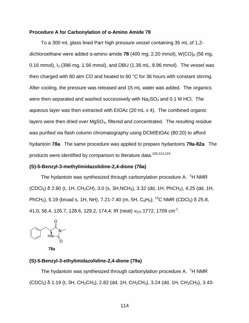
114
Procedure A for Carbonylation of α-Amino Amide 78
To a 300 mL glass lined Parr high pressure vessel containing 35 mL of 1,2-
dichloroethane were added α-amino amide 78 (400 mg, 2.20 mmol), W(CO)6 (56 mg,
0.16 mmol), I2 (396 mg, 1.56 mmol), and DBU (1.36 mL, 8.96 mmol). The vessel was
then charged with 80 atm CO and heated to 60 °C for 36 hours with constant stirring.
After cooling, the pressure was released and 15 mL water was added. The organics
were then separated and washed successively with Na2SO3 and 0.1 M HCl. The
aqueous layer was then extracted with EtOAc (20 mL x 4). The combined organic
layers were then dried over MgSO4, filtered and concentrated. The resulting residue
was purified via flash column chromatography using DCM/EtOAc (80:20) to afford
hydantoin 78a. The same procedure was applied to prepare hydantoins 79a-82a. The
products were identified by comparison to literature data.165,214,215
(S)-5-Benzyl-3-methylimidazolidine-2,4-dione (78a)
The hydantoin was synthesized through carbonylation procedure A. 1H NMR
(CDCl3) δ 2.80 (t, 1H, CH2CH), 3.0 (s, 3H,NCH3), 3.32 (dd, 1H, PhCH2), 4.25 (dd, 1H,
PhCH2), 5.19 (broad s, 1H, NH), 7.21-7.40 (m, 5H, C6H5); 13C NMR (CDCl3) δ 25.8,
41.0, 56.4, 126.7, 128.6, 129.2, 174,4; IR (neat) νCO 1772, 1709 cm-1.
(S)-5-Benzyl-3-ethylimidazolidine-2,4-dione (79a)
The hydantoin was synthesized through carbonylation procedure A. 1H NMR
(CDCl3) δ 1.19 (t, 3H, CH2CH3), 2.82 (dd, 1H, CH2CH3), 3.24 (dd, 1H, CH2CH3), 3.43-
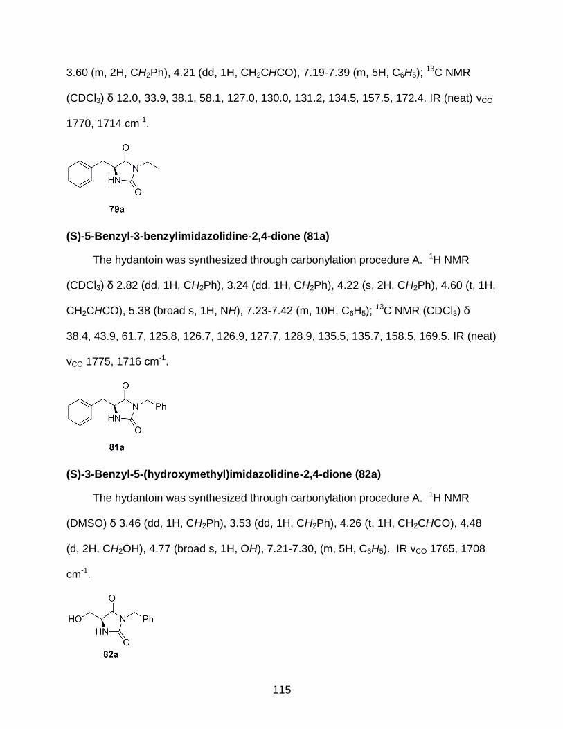
115
3.60 (m, 2H, CH2Ph), 4.21 (dd, 1H, CH2CHCO), 7.19-7.39 (m, 5H, C6H5); 13C NMR
(CDCl3) δ 12.0, 33.9, 38.1, 58.1, 127.0, 130.0, 131.2, 134.5, 157.5, 172.4. IR (neat) νCO
1770, 1714 cm-1.
(S)-5-Benzyl-3-benzylimidazolidine-2,4-dione (81a)
The hydantoin was synthesized through carbonylation procedure A. 1H NMR
(CDCl3) δ 2.82 (dd, 1H, CH2Ph), 3.24 (dd, 1H, CH2Ph), 4.22 (s, 2H, CH2Ph), 4.60 (t, 1H,
CH2CHCO), 5.38 (broad s, 1H, NH), 7.23-7.42 (m, 10H, C6H5); 13C NMR (CDCl3) δ
38.4, 43.9, 61.7, 125.8, 126.7, 126.9, 127.7, 128.9, 135.5, 135.7, 158.5, 169.5. IR (neat)
νCO 1775, 1716 cm-1.
(S)-3-Benzyl-5-(hydroxymethyl)imidazolidine-2,4-dione (82a)
The hydantoin was synthesized through carbonylation procedure A. 1H NMR
(DMSO) δ 3.46 (dd, 1H, CH2Ph), 3.53 (dd, 1H, CH2Ph), 4.26 (t, 1H, CH2CHCO), 4.48
(d, 2H, CH2OH), 4.77 (broad s, 1H, OH), 7.21-7.30, (m, 5H, C6H5). IR νCO 1765, 1708
cm-1.

116
Procedure B for Carbonylation of α-Amino Amide 86
To a 300 mL glass lined Parr high pressure vessel containing 20 mL of
dichloromethane were added α-amino amide 86 (250 mg, 1.1 mmol), W(CO)6 (29 mg,
0.081 mmol), I2 (195 mg, 0.770 mmol), and DBU (187 mg, 1.22 mmol). The vessel was
then charged with 80 atm CO and heated to 35 °C for 24 hours with constant stirring.
After cooling, the pressure was released and 20 mL of 95/5 (DCM:MeOH) was added.
The organics were then washed immediately with Na2SO3 and separated. The aqueous
layer was then extracted with ethyl acetate (2 x 20 mL). The combined organic layers
were then dried with MgSO4, filtered, and concentrated. The resulting residue was then
purified via flash column chromatography using DCM/EtOAc (80:20) to afford hydantoin
86a, also known as phenytoin. The same procedure was applied to prepare hydantoins
83a and 85a. Phenytoin was identified by comparison to a commercially available
sample. Other products were identified by comparison to literature data.216,217
Hydantoin 83a
The hydantoin was synthesized through carbonylation procedure B. 1H NMR
(CDCl3/CD3OD) δ 3.35 (dd, 1H, BnCHCO), 4.33 (d 2H, PhCH2CH), 6.78 (d, 2H,
PhCH2N), 7.21-7.47(m, 10H, C6H5), 8.98 (broad s, 1H, NH) 7.24-7.45 (m, 10H, C6H5).
13C NMR (CDCl3/CD3OD) δ 37.2, 49.8, 69.5, 122.1, 122.7, 123.1, 125.1, 128.3, 129.0,
140.8, 144.2, 165.6, 175.6. IR (solid) νCO 1738, 1651 cm-1.

117
3-Benzyl-5,5-diphenylimidazoidine-2,4-dione 85a
The hydantoin was synthesized through carbonylation procedure B. 1H NMR
(CDCl3/CD3OD) δ 4.26 (s, 2H, PhCH2N), 7.15-7.60 (m, 15 H, C6H5), 7.88 (broad s, 1H,
NH). IR (solid) νCO 1734, 1650 cm-1.
Phenytoin, 86a
The hydantoin was synthesized through carbonylation procedure B. 1H NMR
(DMSO) δ 7.15-7.60 (m, 10 H, C6H5), 9.30 (broad s, 1H, NH), 10.54. IR (solid) νCO
1729, 1660 cm-1. 13C NMR (DMSO) δ 68.4, 122.3, 123.5, 124.3, 137.5, 164.1, 172.6.
IR (solid) CO 1732, 1654 cm-1.
General Procedure C for N-Boc Protection of β-Amino Acids to Form 100
In a 100 mL round bottom flask, 10.0 mmol of (±)-3-aminobutanoic acid (1.03 g)
was slurried in 10 mL tert-butanol and 10 mL 1.0 N NaOH then cooled to 0 °C in
accordance with literature procedure.204 Then 11.0 mmol Boc2O (2.40 g) was added in
one portion, strired at 0 °C for 10 minutes, then allowed to warm to room temperature.
The pH of the reaction mixture was adjusted continuously to pH 9-10 by adding 4.0 N
NaOH. The reaction stirred for a total of 3 hours, after which the mixture was
concentrated to approximately 15 mL by reduced pressure. The remaining aqueous

118
layer was covered with EtOAc and cooled to 0 °C where it was then acidified to pH 1-2
using 5.0 N HCl. The organics were separated and the aqueous layer extracted with
EtOAc three times with 25 mL. The organics were combined and dried over MgSO4,
filtered and volatiles were then removed by reduced pressure. The resulting oil was
purified by column chromatography starting with 3% MeOH/DCM and gradient shifting
to 5% MeOH/DCM after 500 mL, resulting in 1.78 g of amino acid 100. Yield 88%.
Product identification was made by comparison to literature data.204 1H NMR (CDCl3) δ
1.21 (d, 3H, CH3), 1.40 (s, 9H, C(CH3)3), 2.42 (d, 2H, CH2), 3.96 (m, 1H, CHCH3), 5.2
(broad s, 1H, BocNH). 13C NMR (CDCl3) δ 20.9, 28.6, 43.0, 43.8, 70.6, 155.7, 170.9.
3-((tert-butoxycarbonyl)amino)-3-phenylpropanoic acid 101
The procedure followed was the same as described in general procedure C to
afford compound 100. 1H NMR (CDCl3) δ 1.40 (broad s, 9H, C(CH3)3), 2.84 (broad s,
2H, CH2), 5.09 (broad s, 1H, CHPh), 5.54 (broad s, 1H, NHBoc), 7.25-7.36 (m, 5H,
C6H5), 9.90 (broad s, 1H, COOH). 13C NMR (CDCl3) δ 21.1, 28.5, 31.8, 71.2, 126.4,
127.7, 128.8, 155.2, 164.8, 181.8. HRMS [M+Na]+ calcd 288.1206, found 288.1193.
3-((tert-butoxycarbonyl)amino)-4-phenylbutanoic acid 102
The procedure followed was the same as described in general procedure C to
afford compound 100. 1H NMR (CDCl3) δ 1.41 (s, 9H, C(CH3)3), 2.53 (d, 2H,

119
CHCH2COOH), 2.86 (m, 1H, NHCHCH2), 4.18 (d, 2H, PhCH2), 7.20-7.32 (m, 5H, C6H5).
13C NMR (CDCl3) δ 21.5, 28.4, 39.3, 43.8, 72.4, 126.7, 128.0, 129.5, 138.3, 155.2,
170.9.
3-((tert-butoxycarbonyl)amino)-4-methylpentanoic acid 103
The procedure followed was the same as described in general procedure C to
afford compound 100. 1H NMR (CDCl3) δ 0.92 (d, 6H, CH(CH3)2), 1.44 (s, 9H,
C(CH3)3), 1.86 (m, 1H, CH(CH3)2), 2.55 (d, 2H, CH2COOH), 3.76 (m, 1H,
CHNHCHCH2). 13C NMR (CDCl3) δ 18.7, 19.6, 28.6, 31.9, 37.4, 63.1, 155.9, 177.3.
General Procedure D for Mixed Anhydride Coupling of β-Amino Acid 99 to Form 104
Into a 100 mL round bottom flask were placed 5.29 mmol of N-Boc-β-alanine (1.00
g) and 6.6 mmol N-methylmorpholine (0.66 g). The flask was cooled to -78 °C and 6.61
mmol isobutylchloroformate (0.88 g) was added and stirred for 5 minutes. Then 6.61
mmol benzylamine (0.71 mL) was added and stirred for 10 minutes before allowing the
flask to warm to room temperature. The reaction then stirred for one and a half hours
after which solid was removed and washed with hexanes. The filtrate was concentrated
by reduced pressure then re-suspended in hexanes and filtered again. The solids were
combined and purified by column chromatography 95/5 (DCM:MeOH). Isolated 1.37 g,
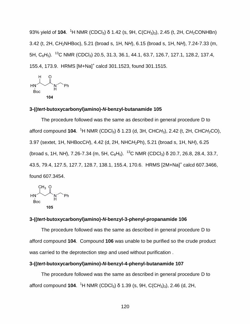
120
93% yield of 104. 1H NMR (CDCl3) δ 1.42 (s, 9H, C(CH3)3), 2.45 (t, 2H, CH2CONHBn)
3.42 (t, 2H, CH2NHBoc), 5.21 (broad s, 1H, NH), 6.15 (broad s, 1H, NH), 7.24-7.33 (m,
5H, C6H5). 13C NMR (CDCl3) 20.5, 31.3, 36.1, 44.1, 63.7, 126.7, 127.1, 128.2, 137.4,
155.4, 173.9. HRMS [M+Na]+ calcd 301.1523, found 301.1515.
3-((tert-butoxycarbonyl)amino)-N-benzyl-butanamide 105
The procedure followed was the same as described in general procedure D to
afford compound 104. 1H NMR (CDCl3) δ 1.23 (d, 3H, CHCH3), 2.42 (t, 2H, CHCH2CO),
3.97 (sextet, 1H, NHBocCH), 4.42 (d, 2H, NHCH2Ph), 5.21 (broad s, 1H, NH), 6.25
(broad s, 1H, NH), 7.26-7.34 (m, 5H, C6H5). 13C NMR (CDCl3) δ 20.7, 26.8, 28.4, 33.7,
43.5, 79.4, 127.5, 127.7, 128.7, 138.1, 155.4, 170.6. HRMS [2M+Na]+ calcd 607.3466,
found 607.3454.
3-((tert-butoxycarbonyl)amino)-N-benzyl-3-phenyl-propanamide 106
The procedure followed was the same as described in general procedure D to
afford compound 104. Compound 106 was unable to be purified so the crude product
was carried to the deprotection step and used without purification .
3-((tert-butoxycarbonyl)amino)-N-benzyl-4-phenyl-butanamide 107
The procedure followed was the same as described in general procedure D to
afford compound 104. 1H NMR (CDCl3) δ 1.39 (s, 9H, C(CH3)3), 2.46 (d, 2H,

121
CHCH2CO), 4.12 (m, 1H, CHNHBoc), 4.40 (d, 2H, NHCH2Ph), 4.47 (d, 2H, PhCH2CH),
5.42 (broad s, 1H, NH), 5.94 (broad s, 1H, NH), 7.15-7.34 (m, 10H, aromatics). 13C
NMR (CDCl3) δ 20.1, 28.6, 33.7, 43.8, 49.8, 59.6, 126.7, 127.7, 128.0, 128.7, 129.0,
129.5, 138.2, 138.6, 155.7, 170.9.
3-((tert-butoxycarbonyl)amino)-N-benzyl-4-methyl-pentanamide 108
The procedure followed was the same as described in general procedure D to
afford compound 104. 1H NMR (CDCl3) δ 0.91 (d, 6H, CH(CH3)2), 1.39 (s, 9H,
C(CH3)3), 1.83 (m, 1H, CH(CH3)2), 2.46 (d, 2H, NHCHCH2), 3.67 (m, 1H, NHCHCH2),
4.41 (d, 2H, NHCH2Ph), 5.07 (broad s, 1H, NH), 6.47 (broad s, 1H, NH). 13C NMR
(CDCl3) δ 19.4, 28.3, 32.1, 39.5, 43.6, 53.4, 63.1, 127.4, 127.7, 128.6, 138.2, 163.4,
166.7.
General Procedure E for Deprotection of N-Boc β-Amino Amide 104 to Form 109
Compound 104, 4.91 mmol (1.36 g), was placed in a round bottom flask and
dissolved in 10 mL DCM. Then 24.6 mmol (6.13 mL) of 4.0 M HCl in dioxane was
added and stirred for 18 hours. After reaction time, the excess HCl was removed by
sparging with N2. The resulting solid was purified via column chromatography using 5%
MeOH in DCM and gradient shifting 2.5% MeOH increases per 400 mL eluent used until
a final percentage of 15% MeOH/DCM was achieved. Isolated 109, 0.832 g, 95% yield
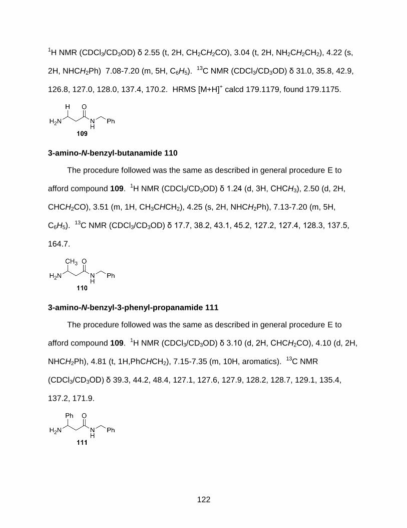
122
1H NMR (CDCl3/CD3OD) δ 2.55 (t, 2H, CH2CH2CO), 3.04 (t, 2H, NH2CH2CH2), 4.22 (s,
2H, NHCH2Ph) 7.08-7.20 (m, 5H, C6H5). 13C NMR (CDCl3/CD3OD) δ 31.0, 35.8, 42.9,
126.8, 127.0, 128.0, 137.4, 170.2. HRMS [M+H]+ calcd 179.1179, found 179.1175.
3-amino-N-benzyl-butanamide 110
The procedure followed was the same as described in general procedure E to
afford compound 109. 1H NMR (CDCl3/CD3OD) δ 1.24 (d, 3H, CHCH3), 2.50 (d, 2H,
CHCH2CO), 3.51 (m, 1H, CH3CHCH2), 4.25 (s, 2H, NHCH2Ph), 7.13-7.20 (m, 5H,
C6H5). 13C NMR (CDCl3/CD3OD) δ 17.7, 38.2, 43.1, 45.2, 127.2, 127.4, 128.3, 137.5,
164.7.
3-amino-N-benzyl-3-phenyl-propanamide 111
The procedure followed was the same as described in general procedure E to
afford compound 109. 1H NMR (CDCl3/CD3OD) δ 3.10 (d, 2H, CHCH2CO), 4.10 (d, 2H,
NHCH2Ph), 4.81 (t, 1H,PhCHCH2), 7.15-7.35 (m, 10H, aromatics). 13C NMR
(CDCl3/CD3OD) δ 39.3, 44.2, 48.4, 127.1, 127.6, 127.9, 128.2, 128.7, 129.1, 135.4,
137.2, 171.9.
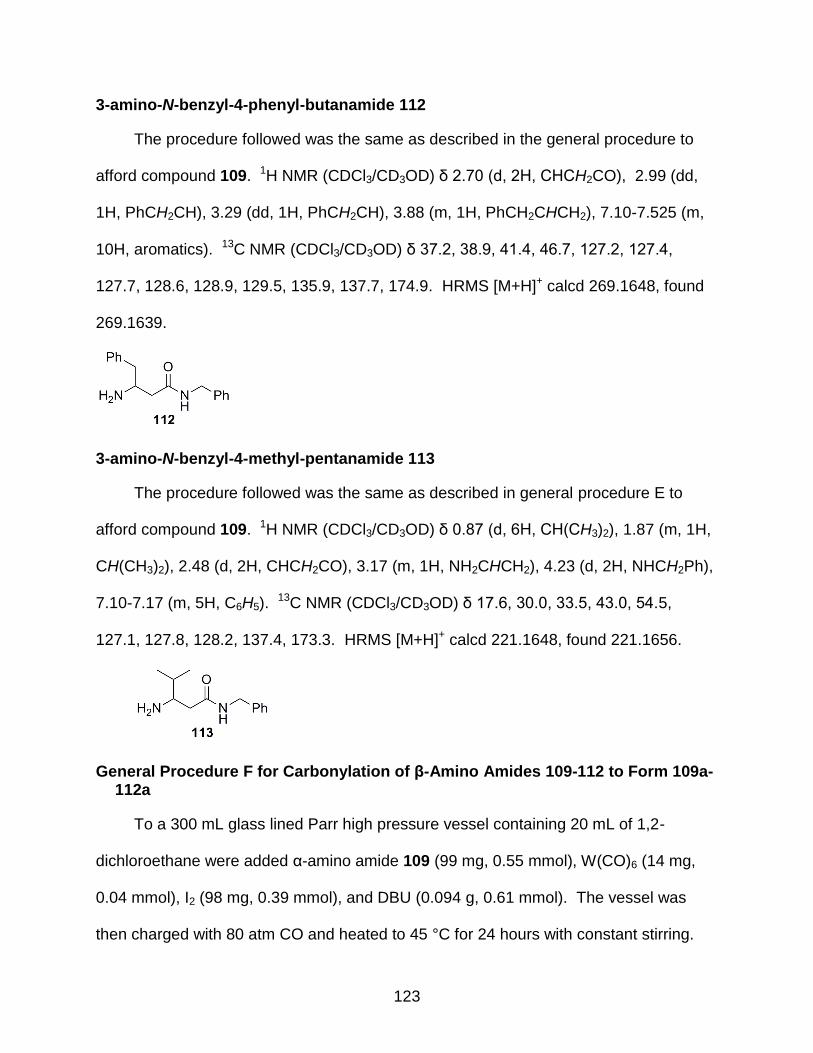
123
3-amino-N-benzyl-4-phenyl-butanamide 112
The procedure followed was the same as described in the general procedure to
afford compound 109. 1H NMR (CDCl3/CD3OD) δ 2.70 (d, 2H, CHCH2CO), 2.99 (dd,
1H, PhCH2CH), 3.29 (dd, 1H, PhCH2CH), 3.88 (m, 1H, PhCH2CHCH2), 7.10-7.525 (m,
10H, aromatics). 13C NMR (CDCl3/CD3OD) δ 37.2, 38.9, 41.4, 46.7, 127.2, 127.4,
127.7, 128.6, 128.9, 129.5, 135.9, 137.7, 174.9. HRMS [M+H]+ calcd 269.1648, found
269.1639.
3-amino-N-benzyl-4-methyl-pentanamide 113
The procedure followed was the same as described in general procedure E to
afford compound 109. 1H NMR (CDCl3/CD3OD) δ 0.87 (d, 6H, CH(CH3)2), 1.87 (m, 1H,
CH(CH3)2), 2.48 (d, 2H, CHCH2CO), 3.17 (m, 1H, NH2CHCH2), 4.23 (d, 2H, NHCH2Ph),
7.10-7.17 (m, 5H, C6H5). 13C NMR (CDCl3/CD3OD) δ 17.6, 30.0, 33.5, 43.0, 54.5,
127.1, 127.8, 128.2, 137.4, 173.3. HRMS [M+H]+ calcd 221.1648, found 221.1656.
General Procedure F for Carbonylation of β-Amino Amides 109-112 to Form 109a-112a
To a 300 mL glass lined Parr high pressure vessel containing 20 mL of 1,2-
dichloroethane were added α-amino amide 109 (99 mg, 0.55 mmol), W(CO)6 (14 mg,
0.04 mmol), I2 (98 mg, 0.39 mmol), and DBU (0.094 g, 0.61 mmol). The vessel was
then charged with 80 atm CO and heated to 45 °C for 24 hours with constant stirring.

124
After cooling, the pressure was released and 20 mL of 95/5 (DCM:MeOH) was added.
The organics were then washed immediately with Na2SO3 and separated. The aqueous
layer was then extracted with 3:1 CHCl3/EtOH solution (3 x 20 mL). The combined
organic layers were then dried with MgSO4, filtered, and concentrated. The resulting
residue was then purified via flash column chromatography using DCM/EtOAc (80:20)
to afford 3-benzyl-dihydropyrimidine-2,4(1H)-dione 109a. 1H NMR (CDCl3/CD3OD) δ
2.49 (t, 2H, CH2CH2CONCH2Ph), 3.53 (q, 2H, NHCH2CH2), 4.39 (d, 2H, NCH2Ph), 7.19-
7.34 (m, 5H, C6H5). 13C NMR (CDCl3/CD3OD) δ 43.11, 45.21, 62.10, 127.1, 127.4,
128.3, 137.9, 159.0, 170.9. IR (solid) νCO 1726, 1678 cm-1. The product was identified
by comparison to literature values.206
Urea 110a
The procedure followed was the same as described in general procedure F to
afford compound 110a. 1H NMR (DMSO) δ 1.01 (d, 3H, CHCH3), 2.31 (d, 2H,
CHCH2CO), 3.92 (m, 1H, CH3CHCH2), 4.25 (d, 2H, NCH2Ph), 7.21-7.29 (m, 5H, C6H5),
8.33 (s, 1H, NH). 13C NMR (DMSO) δ 15.9, 31.8, 32.3, 57.9, 127.4, 127.9, 128.9,
134.8, 154.2, 171.0. IR (solid) νCO 1651, 1687 cm-1.

125
Urea 111a
The procedure followed was the same as described in general procedure F to
afford compound 111a. 1H NMR (DMSO) δ 2.62 (d, 2H, CHCH2CO), 4.21 (t, 1H,
PhCHCH2), 5.10 (d, 2H, NCH2Ph), 7.13-7.28 (m, 10H, C6H5). 13C NMR (DMSO) δ 23.9,
43.9, 50.4, 126.2, 126.7, 126.9, 127.1, 127.6, 128.8, 132.1, 133.6, 153.0, 178.4. IR
(solid) νCO 1665, 1698 cm-1.
Urea 112a
The procedure followed was the same as described in general procedure F to
afford compound 112a. 1H NMR (CDCl3/CD3OD) δ 2.33 (d, 2H, CHCH2CO), 2.81 (d,
2H, PhCH2CH), 4.14 (quintet, 1H, PhCH2CHCH2), 4.36 (d, 2H, NCH2Ph), 7.12-7.34 (m,
10H, aromatics), 7.71 (broad s, 1H, NH). 13C NMR (CDCl3/CD3OD) δ 44.7, 44.8, 47.6,
53.2, 130.5, 131.4, 131.7, 132.4, 132.7, 133.4, 142.1, 142.3, 162.2, 175.9. IR (solid)
νCO 1637, 1684 cm-1. HRMS [M+H]+ calcd 563.3017, found 563.3013.
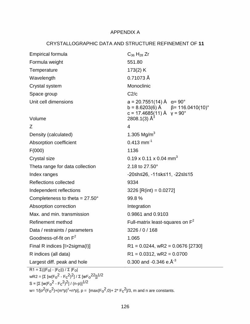
126
APPENDIX A
CRYSTALLOGRAPHIC DATA AND STRUCTURE REFINEMENT OF 11
Empirical formula C36 H28 Zr
Formula weight 551.80
Temperature 173(2) K
Wavelength 0.71073 Å
Crystal system Monoclinic
Space group C2/c
Unit cell dimensions a = 20.7551(14) Å α= 90° b = 8.6203(6) Å β= 116.0410(10)° c = 17.4685(11) Å γ = 90°
Volume 2808.1(3) Å3
Z 4
Density (calculated) 1.305 Mg/m3
Absorption coefficient 0.413 mm-1
F(000) 1136
Crystal size 0.19 x 0.11 x 0.04 mm3
Theta range for data collection 2.18 to 27.50°
Index ranges -20≤h≤26, -11≤k≤11, -22≤l≤15
Reflections collected 9334
Independent reflections 3226 [R(int) = 0.0272]
Completeness to theta = 27.50° 99.8 %
Absorption correction Integration
Max. and min. transmission 0.9861 and 0.9103
Refinement method Full-matrix least-squares on F2
Data / restraints / parameters 3226 / 0 / 168
Goodness-of-fit on F2 1.065
Final R indices [I>2sigma(I)] R1 = 0.0244, wR2 = 0.0676 [2730]
R indices (all data) R1 = 0.0312, wR2 = 0.0700
Largest diff. peak and hole 0.300 and -0.346 e.Å-3
R1 = Σ(||Fo| - |Fc||) / Σ |Fo|
wR2 = [Σ [w(Fo2 - Fc
2)2] / Σ [ o22]]1/2
S = [Σ [w(Fo2 - Fc
2)2] / (n-p)]1/2
w= 1/[σ2(Fo2)+(m*p)
2+n*p], p = [max(Fo
2,0)+ 2* Fc2]/3, m and n are constants.

127
LIST OF REFERENCES
1. Parmeter, J. E.; Smith, D. C.; Healy, M. D. J. Vac. Sci. Technol., A 1994, 12, 2107-2113.
2. He, X.-M.; Shu, L.; Li, H.-B.; Weng, D. J. Mater. Res. 1999, 14, 615-618. 3. Mackie, W. A.; Xie, T. B.; Davis, P. R. J. Vac. Sci. Technol. B 1995, 13, 2459-
2463. 4. Holmberg, K.; Matthews, A. Coatings Tribology: Properties, Techniques, and
Applications in Surface Engineering; Elsevier: Amsterdam, 1994. 5. Reynolds, G. H. J. Nucl. Mater. 1974, 50, 215-216. 6. Xie, T.; Mackie, W. A.; Davis, P. R. J. Vac. Sci. Technol., B. 1996, 14, 2090. 7. D'Alessio, L.; Santagata, A.; Teghil, R.; Zaccagnino, M.; Zaccardo, I.; Marotta, V.;
Ferro, D.; De Maria, G. Appl. Surf. Sci. 2000, 168, 284-287. 8. Zhang, Q.; He, J.; Liu, W.; Zhong, M. Surf. Coat. Technol. 2003, 162, 140-146. 9. Chen, C.-S.; Liu, C.-P.; Tsao, C.-Y. A. Thin Solid Films 2005, 479, 130-136. 10. Hollabaugh, C. M.; Wahman, L. A.; Reiswig, R. D.; White, R. W.; Wagner, P.
Nucl. Technol. 1977, 35, 527-535. 11. Ogawa, T.; Ikawa, K.; Iwamoto, K. J. Mater. Sci. 1979, 14, 125-132. 12. Wagner, P.; Wahman, L. A.; White, R. W.; Hollabaugh, C. M.; Reiswig, R. D. J.
Nucl. Mater. 1976, 62, 221-228. 13. Ducarroir, M.; Salles, P.; Bernard, C. J. Electrochem. Soc. 1985, 132, 221-228. 14. Liu, Q.; Zhang, L.; Cheng, L.; Wang, Y. J. Coat. Technol. Res. 2009, 6, 269-273. 15. Pattanaik, A. K.; Sarin, V. K. In Chemical Vapor Deposition; Park, J. H., Ed.;
ASM International: Materials Park, 2001; Vol. 2, p 23. 16. Samoilenko, V. G.; Pereselentseva, L. N. Powder Metall. Met. Ceram. 1975, 14,
725-728. 17. Brüggert, M.; Hu, Z.; Hüttinger, K. J. Carbon 1999, 37, 2021-2030. 18. Pierson, H. O. Handbook of Chemical Vapor Deposition (CVD): Principles,
Technology, and Applications; William Andrew Publishing: New York, 1992.

128
19. Ogawa, T.; Ikawa, K.; Iwamoto, K. J. Nucl. Mater. 1981, 97, 104-112. 20. Scussel, H. J. ASM Handbook; ASM Int.: New York, 1992; Vol. 18. 21. Glass, J. A., Jr.; Palmisiano, N., Jr.; Welsh, R. E. Mater. Res. Soc. Symp. Proc.
1999, 555, 185-190. 22. Blair, H. T.; Carroll, D. W.; Matthews, R. B. AIP Conf. Proc. 1991, 217, 1052-
1058. 23. Wu, Y. D.; Peng, Z. H.; Chan, K. W. K.; Liu, X. Z.; Tuinman, A. A.; Xue, Z. L.
Organometallics 1999, 18, 2081-2090. 24. Girolami, G. S.; Jensen, J. A.; Gozum, J. E.; Pollina, D. M. Mater. Res. Soc.
Symp. Proc. 1988, 121, 429-438. 25. Smith, D. C.; Rubiano, R. R.; Healy, M. D.; Springer, R. W. Proc. - Electrochem.
Soc. 1993, 93-2, 417-424. 26. Won, Y. S.; Varanasi, V. G.; Kryliouk, O.; Anderson, T. J.; McElwee-White, L.;
Perez, R. J. J. Cryst. Growth 2007, 307, 302-308. 27. Won, Y. S.; Kim, Y. S.; Varanasi, V. G.; Kryliouk, O.; Anderson, T. J.; Sirimanne,
C. T.; McElwee-White, L. J. Cryst. Growth 2007, 304, 324-332. 28. Sirimanne, C. T.; McElwee-White, L.; Won, Y. S.; Kryliouk, O.; Anderson, T. J.
Abstr. Pap. - Am. Chem. Soc. 2005, 230, U2024-U2025. 29. Polk, J. An Overview of JPL's Advanced Propulsion Concepts Research
Program, 2001. 30. Temple, D. Mater. Sci. Eng., R. 1999, 24, 185-239. 31. Smith, D. C.; Rubiano, R. R.; Healy, M. D.; Springer, R. W. Mater. Res. Soc.
Symp. Proc. 1993, 282, 643-649. 32. Girolami, G. S.; Jensen, J. A.; Pollina, D. M.; Williams, W. S.; Kaloyeros, A. E.;
Allocca, C. M. J. Am. Chem. Soc. 1987, 109, 1579-1580. 33. Cheon, J.; Rogers, D. M.; Girolami, G. S. J. Am. Chem. Soc. 1997, 119, 6804-
6813. 34. Cheon, J.; Dubois, L. H.; Girolami, G. S. J. Am. Chem. Soc. 1997, 119, 6814-
6820. 35. Wu, Y. D.; Peng, Z. H.; Xue, Z. L. J. Am. Chem. Soc. 1996, 118, 9772-9777.

129
36. Wojcicki, A. Inorg. Chem. Commun. 2002, 5, 82-97. 37. Pedly, J. B.; Naylor, R. D.; Kirby, S. P. Thermochemical Data for Organic
Compunds; Chapman and Hall: London, 1986. 38. Doherty, S.; Corrigan, J. F.; Carty, A. J.; Sappa, E. Adv. Organomet. Chem.
1995, 37, 39-130. 39. Blosser, P. W.; Schimpff, D. G.; Gallucci, J. C.; Wojcicki, A. Organometallics
1993, 12, 1993-1995. 40. Casey, C. P.; Yi, C. S. J. Am. Chem. Soc. 1992, 114, 6597-6598. 41. Dewar, M. J. S.; Thiel, W. J. Am. Chem. Soc. 1977, 99, 4907-4917. 42. Hughes, A. K.; Kingsley, A. J. J. Organomet. Chem. 1997, 539, 109-114. 43. McAlexander, L. H.; Li, L.; Yang, Y.; Pollitte, J. L.; Xue, Z. Inorg. Chem. 1998, 37,
1423-1426. 44. Lai, T. Y. Bull. Soc. Chim. Fr. 1933, 53, 1533. 45. Lappin, G. R. J. Am. Chem. Soc. 1949, 71, 3966-3968. 46. Gaudemar, M. Ann. Chim. 1956, 1, 190-202. 47. Lewekebandara, T. S.; Sheridan, P. H.; Heeg, M. J.; Rheingold, A. L.; Winter, C.
H. Inorg. Chem. 1994, 33, 5879-5889. 48. Interrante, L. V.; Sigel, G. A.; Garbauskas, M.; Hejna, C.; Slack, G. A. Inorg.
Chem. 1989, 28, 252-257. 49. Bchir, O. J.; Green, K. M.; Hlad, M. S.; Anderson, T. J.; Brooks, B. C.; Wilder, C.
B.; Powell, D. H.; McElwee-White, L. J. Organomet. Chem. 2003, 684, 338-350. 50. Blosser, P. W.; Gallucci, J. C.; Wojcicki, A. J. Organomet. Chem. 2000, 597, 125-
132. 51. Costuas, K.; Saillard, J.-Y. Chem. Commun. 1998, 18, 2047-2048. 52. Gleiter, R.; Bethke, S.; Okubo, J.; Jonas, K. Organometallics 2001, 20, 4274-
4278. 53. Bendjaballah, S.; Kahlal, S.; Costuas, K.; Bévillon, E.; Saillard, J.-Y. Chem.--Eur.
J. 2006, 12, 2048-2065.

130
54. Summerscales, O. T.; Cloke, F. G. N. Coord. Chem. Rev. 2006, 250, 1122-1140. 55. Becke, A. D. J. Chem. Phys. 1993, 98, 5648-5652. 56. Lee, C.; Yang, W.; Parr, R. G. Phys. Rev. B 1988, 37, 785-789. 57. Vosko, S. H.; Wilk, L.; Nusair, M. Can. J. Phys. 1980, 58, 1200-1211. 58. Stephens, P. J.; Devlin, F. J.; Chabalowski, C. F.; Frisch, M. J. J. Phys. Chem.
1994, 98, 11623-11627. 59. Becconsall, J. K.; O'Brien, S. Chem. Commun. 1966, 302-303. 60. Jennings, J. R. J. Mol. Catal. 1990, 58, 95-105. 61. Chrusciel, R. A.; Strohbach, J. W. Curr. Top. Med. Chem. 2004, 4, 1097-1114. 62. De Lucca, G. V.; Lam, P. Y. S. Drugs Future 1998, 23, 987-994. 63. Semple, G.; Ryder, H.; Rooker, D. P.; Batt, A. R.; Kendrick, D. A.; Szelke, M.;
Ohta, M.; Satoh, M.; Nishida, A.; Akuzawa, S.; Miyata, K. J. Med. Chem. 1997, 40, 331-341.
64. Dragovich, P. S.; Barker, J. E.; French, J.; Imbacuan, M.; Kalish, V. J.; Kissinger,
C. R.; Knighton, D. R.; Lewis, C. T.; Moomaw, E. W.; Parge, H. E.; Pelletier, L. A. K.; Prins, T. J.; Showalter, R. E.; Tatlock, J. H.; Tucker, K. D.; Villafranca, J. E. J. Med. Chem. 1996, 39, 1872-1884.
65. vonGeldern, T. W.; Kester, J. A.; Bal, R.; WuWong, J. R.; Chiou, W.; Dixon, D.
B.; Opgenorth, T. J. J. Med. Chem. 1996, 39, 968-981. 66. Vishnyakova, T. P.; Golubeva, I. A.; Glebova, E. V. Russ. Chem. Rev. (Engl.
Transl.) 1985, 54, 249-261. 67. DeLucca, G. V.; Liang, J.; Aldrich, P. E.; Calabrese, J.; Cordova, B.; Klabe, R.
M.; Rayner, M. M.; Chang, C. H. J. Med. Chem. 1997, 40, 1707-1719. 68. Lam, P. Y.-S.; Jadhav, P. K.; Eyermann, C. J.; Hodge, C. N.; De, L. G. V.;
Rodgers, J. D. WO Patent 9419329, 1994 69. Lam, P. Y. S.; Jadhav, P. K.; Eyermann, C. J.; Hodge, C. N.; Ru, Y.; Bacheler, L.
T.; Meek, J. L.; Otto, M. J.; Rayner, M. M.; Wong, Y. N.; Chang, C. H.; Weber, P. C.; Jackson, D. A.; Sharpe, T. R.; Erickson-Viitanen, S. Science 1994, 263, 380-384.
131
70. Qian, F.; McCusker, J. E.; Zhang, Y.; Main, A. D.; Chlebowski, M.; Kokka, M.; McElwee-White, L. J. Org. Chem. 2002, 67, 4086-4092.
71. Ragaini, F. Dalton Trans. 2009, 6251-6266. 72. Giannoccaro, P.; Tommasi, I.; Aresta, M. J. Organomet. Chem. 1994, 476, 13-
18. 73. Sartori, G.; Maggi, R. In Science of Synthesis; Ley, S. V., Knight, J. G., Eds.;
Thieme: Stuttgart, 2005; Vol. 18, pp 665-758. 74. Hegarty, A. F.; Drennan, L. J. In Comprehensive Organic Functional Group
Transformations; Katritzky, A. R., Meth-Cohn, O., Rees, C. W., Eds.; Pergamon: Oxford, 1995; Vol. 6, pp 499-526.
75. Bigi, F.; Maggi, R.; Sartori, G. Green Chem. 2000, 2, 140-148. 76. Hylton, K.-G.; Main, A. D.; McElwee-White, L. J. Org. Chem. 2003, 68, 1615-
1617. 77. Díaz, D. J.; Hylton, K. G.; McElwee-White, L. J. Org. Chem. 2006, 71, 734-738. 78. Trost, B. M. Angew. Chem.-Int. Edit. Engl. 1995, 34, 259-281. 79. Klausener, A.; Jentsch, J.-D. In Applied Homogeneous Catalysis with
Organometallic Compounds (2nd Edition); Cornils, B., Herrmann, W. A., Eds.; VCH: Weinheim, 2002; Vol. 1, pp 164-182.
80. Gabriele, B.; Salerno, G.; Costa, M. In Catalytic Carbonylation Reactions; Beller,
M., Ed.; Springer: Heidelberg, 2006, pp 239-272. 81. McCusker, J. E.; Logan, J.; McElwee-White, L. Organometallics 1998, 17, 4037-
4041. 82. McCusker, J. E.; Qian, F.; McElwee-White, L. J. Mol. Catal. A-Chem. 2000, 159,
11-17. 83. McCusker, J. E.; Grasso, C. A.; Main, A. D.; McElwee-White, L. Org. Lett. 1999,
1, 961-964. 84. McCusker, J. E.; Main, A. D.; Johnson, K. S.; Grasso, C. A.; McElwee-White, L.
J. Org. Chem. 2000, 65, 5216-5222. 85. Li, K. T.; Peng, Y. J. J. Catal. 1993, 143, 631-634.

132
86. Srivastava, S. C.; Shrimal, A. K.; Srivastava, A. J. Organomet. Chem. 1991, 414, 65-69.
87. Dombek, B. D.; Angelici, R. J. J. Catal. 1977, 48, 433-435. 88. Li-Juan, C.; Fu-Ming, M.; Guang-Xing, L. Catalysis Communications 2009, 10,
981-985. 89. Park, J. H.; Yoon, J. C.; Chung, K. Y. Adv. Synth. Catal. 2009, 351, 1233-1237. 90. Bassoli, A.; Rindone, B.; Tollari, S.; Chioccara, F. J. Mol. Catal. 1990, 60, 41-48. 91. Benedini, F.; Nali, M.; Rindone, B.; Tollari, S.; Cenini, S.; Lamonica, G.; Porta, F.
J. Mol. Catal. 1986, 34, 155-161. 92. Liu, J. M.; Peng, X. G.; Liu, J.-H.; Zheng, S. Z.; Sun, W.; Xia, C. G. Tetrahedron
Lett. 2007, 48, 929-932. 93. Giannoccaro, P.; Nobile, C. F.; Mastrorilli, P.; Ravasio, N. J. Organomet. Chem.
1991, 419, 251-258. 94. Hoberg, H.; Fañanás, F. J.; Riegel, H. J. J. Organomet. Chem. 1983, 254, 267-
271. 95. Kondo, T.; Kotachi, S.; Tsuji, Y.; Watanabe, Y.; Mitsudo, T. Organometallics
1997, 16, 2562-2570. 96. Kotachi, S.; Kondo, T.; Watanabe, Y. Catal. Lett. 1993, 19, 339-344. 97. Mulla, S. A. R.; Gupte, S. P.; Chaudhari, R. V. J. Mol. Catal. 1991, 67, L7-L10. 98. Mulla, S. A. R.; Rode, C. V.; Kelkar, A. A.; Gupte, S. P. J. Mol. Catal. A-Chem.
1997, 122, 103-109. 99. Durand, D.; Lassau, C. Tetrahedron Lett. 1969, 2329-2330. 100. Alper, H.; Vasapollo, G.; Hartstock, F. W.; Mlekuz, M.; Smith, D. J. H.; Morris, G.
E. Organometallics 1987, 6, 2391-2393. 101. Chiarotto, I.; Feroci, M. J. Org. Chem. 2003, 68, 7137-7139. 102. Choudary, B. M.; Rao, K. K.; Pirozhkov, S. D.; Lapidus, A. L. Synth. Commun.
1991, 21, 1923-1927. 103. Gabriele, B.; Salerno, G.; Mancuso, R.; Costa, M. J. Org. Chem. 2004, 69, 4741-
4750.

133
104. Imada, Y.; Mitsue, Y.; Ike, K.; Washizuka, K.; Murahashi, S. Bull. Chem. Soc. Jpn. 1996, 69, 2079-2090.
105. Ozawa, F.; Soyama, H.; Yanagihara, H.; Aoyama, I.; Takino, H.; Izawa, K.;
Yamamoto, T.; Yamamoto, A. J. Am. Chem. Soc. 1985, 107, 3235-3245. 106. Ozawa, F.; Sugimoto, T.; Yuasa, Y.; Santra, M.; Yamamoto, T.; Yamamoto, A.
Organometallics 1984, 3, 683-692. 107. Shi, F.; Deng, Y. Q.; SiMa, T. L.; Yang, H. Z. Tetrahedron Lett. 2001, 42, 2161-
2163. 108. Ozawa, F.; Yamamoto, A. Chem. Lett. 1982, 865-868. 109. Tsuji, J.; Iwamoto, N. Chem. Commun. 1966, 380. 110. Ronchin, L.; Vavasori, A.; Amadio, E.; Cavinato, G.; Toniolo, L. J. Mol. Catal.
2009, 23, 23-30. 111. Zhao, Y.; Jin, L.; Peng, L.; Lei, A. J. Am. Chem. Soc. 2008, 130, 9429-9433. 112. Grosjean, C.; Novakovic, K.; Scott, S. K.; Whiting, A.; Willis, M. J.; Wright, A. R.
J. Mol. Catal. 2008, 284, 33-39. 113. McCusker, J. E.; Abboud, K. A.; McElwee-White, L. Organometallics 1997, 16,
3863-3866. 114. Fukuoka, S.; Chono, M.; Kohno, M. J. Org. Chem. 1984, 49, 1458-1460. 115. Shi, F.; Deng, Y. Q. Chem. Commun. 2001, 443-444. 116. Shi, F.; Deng, Y. Q. J. Catal. 2002, 211, 548-551. 117. Waller, F. J. EP Patent 195515, 1986 118. Hiwatari, K.; Kayaki, Y.; Okita, K.; Ukai, T.; Shimizu, I.; Yamamoto, A. Bull.
Chem. Soc. Jap. 2004, 77, 2237-2250. 119. Bitsi, G.; Jenner, G. J. Organomet. Chem. 1987, 330, 429-435. 120. Byerley, J. J.; Rempel, G. L.; Takebe, N.; James, B. R. J. Chem. Soc. D. 1971,
1482-1483. 121. Jenner, G.; Bitsi, G. Appl. Catal. 1987, 32, 293-304.

134
122. Süss-Fink, G.; Langenbahn, M.; Jenke, T. J. Organomet. Chem. 1989, 368, 103-109.
123. Tsuji, Y.; Ohsumi, T.; Kondo, T.; Watanabe, Y. J. Organomet. Chem. 1986, 309,
333-344. 124. Chiusoli, G. P.; Costa, M.; Gabriele, B.; Salerno, G. J. Mol. Catal. A-Chem. 1999,
143, 297-310. 125. Giannoccaro, P. J. Organomet. Chem. 1987, 336, 271-278. 126. Gupte, S. P.; Chaudhari, R. V. J. Catal. 1988, 114, 246-258. 127. Sheludyakov, Y. L.; Golodov, V. A. Bull. Chem. Soc. Jpn. 1984, 57, 251-253. 128. Alper, H.; Hartstock, F. W. J. Chem. Soc.-Chem. Commun. 1985, 1141-1142. 129. Pri-Bar, I.; Alper, H. Can. J. Chem.-Rev. Can. Chim. 1990, 68, 1544-1547. 130. Murahashi, S.; Mitsue, Y.; Ike, K. J. Chem. Soc.-Chem. Commun. 1987, 125-
127. 131. Tam, W. J. Org. Chem. 1986, 51, 2977-2981. 132. Fukuoka, S.; Chono, M.; Kohno, M. J. Chem. Soc.-Chem. Commun. 1984, 399-
400. 133. Kelkar, A. A.; Kolhe, D. S.; Kanagasabapathy, S.; Chaudhari, R. V. Ind. Eng.
Chem. Res. 1992, 31, 172-176. 134. Gabriele, B.; Salerno, G.; Brindisi, D.; Costa, M.; Chiusoli, G. P. Org. Lett. 2000,
2, 625-627. 135. Gabriele, B.; Mancuso, R.; Salerno, G.; Costa, M. Chem. Commun. 2003, 486-
487. 136. Aresta, M.; Giannoccaro, P.; Tommasi, I.; Dibenedetto, A.; Lanfredi, A. M. M.;
Ugozzoli, F. Organometallics 2000, 19, 3879-3889. 137. Stahl, S. S. Angew. Chem. Int. Ed. 2004, 43, 3400-3420. 138. Kanagasabapathy, S.; Gupte, S. P.; Chaudhari, R. V. Ind. Eng. Chem. Res.
1994, 33, 1-6. 139. Bolzacchini, E.; Meinardi, S.; Orlandi, M.; Rindone, B. J. Mol. Catal. A-Chem.
1996, 111, 281-287.

135
140. Orejón, A.; Castellanos, A.; Salagre, P.; Castillón, S.; Claver, C. Can. J. Chem. 2005, 83, 764-768.
141. Giannoccaro, P.; De Giglio, E.; Garganno, M.; Aresta, M.; Ferragina, C. J. Mol.
Catal. A-Chem. 2000, 157, 131-141. 142. Presad, K. V.; Chaudhari, R. V. J. Catal. 1994, 145, 204-215. 143. Shi, F.; Zhang, Q.; Ma, Y.; He, Y.; Deng, Y. J. Am. Chem. Soc. 2005, 127, 4182-
4183. 144. Jetz, W.; Angelici, R. J. J. Am. Chem. Soc. 1972, 94, 3799-3802. 145. Davies, S. G.; Mortlock, A. A. Tetrahedron Lett. 1991, 32, 4791-4794. 146. Smith, S. W.; Newman, M. S. J. Am. Chem. Soc. 1968, 90, 1249-1253. 147. De Lucca, G. V. J. Org. Chem. 1998, 63, 4755-4766. 148. Lam, P. Y. S.; Ru, Y.; Jadhav, P. K.; Aldrich, P. E.; DeLucca, G. V.; Eyermann,
C. J.; Chang, C. H.; Emmett, G.; Holler, E. R.; Daneker, W. F.; Li, L. Z.; Confalone, P. N.; McHugh, R. J.; Han, Q.; Li, R. H.; Markwalder, J. A.; Seitz, S. P.; Sharpe, T. R.; Bacheler, L. T.; Rayner, M. M.; Klabe, R. M.; Shum, L. Y.; Winslow, D. L.; Kornhauser, D. M.; Jackson, D. A.; EricksonViitanen, S.; Hodge, C. N. J. Med. Chem. 1996, 39, 3514-3525.
149. Confalone, P. N.; Waltermire, R. E. In Process Chemistry in the Pharmaceutical
Industry; Gadamasetti, K. G., Ed.; Marcel Dekker: New York, 1999, pp 201-219. 150. Lam, P. Y.; Jadhav, P. K.; Eyermann, C. J.; Hodge, C. N.; De Lucca, G. V.;
Rodgers, J. D. US Patent 5,610,294, 1997 151. Nugiel, D. A.; Jacobs, K.; Worley, T.; Patel, M.; Kaltenbach, R. F.; Meyer, D. T.;
Jadhav, P. K.; DeLucca, G. V.; Smyser, T. E.; Klabe, R. M.; Bacheler, L. T.; Rayner, M. M.; Seitz, S. P. J. Med. Chem. 1996, 39, 2156-2169.
152. Rossano, L. T.; Lo, Y. S.; Anzalone, L.; Lee, Y. C.; Meloni, D. J.; Moore, J. R.;
Gale, T. M.; Arnett, J. F. Tetrahedron Lett. 1995, 36, 4967-4970. 153. Hodge, C. N.; Aldrich, P. E.; Bacheler, L. T.; Chang, C. H.; Eyermann, C. J.;
Garber, S.; Grubb, M.; Jackson, D. A.; Jadhav, P. K.; Korant, B.; Lam, P. Y. S.; Maurin, M. B.; Meek, J. L.; Otto, M. J.; Rayner, M. M.; Reid, C.; Sharpe, T. R.; Shum, L.; Winslow, D. L.; EricksonViitanen, S. Chem. Biol. 1996, 3, 301-314.
154. Pierce, M. E.; Harris, G. D.; Islam, Q.; Radesca, L. A.; Storace, L.; Waltermire, R.
E.; Wat, E.; Jadhav, P. K.; Emmett, G. C. J. Org. Chem. 1996, 61, 444-450.
136
155. DeClercq, P. J. Chem. Rev. 1997, 97, 1755-1792. 156. Zhang, Y.; Forinash, K.; Phillips, C. R.; McElwee-White, L. Green Chem. 2005, 7,
451-455. 157. Mehta, N. B.; Diuguid, C. A. R.; Soroko, F. E. J. Med. Chem. 1981, 24, 465-468. 158. Gutschow, M.; Hecker, T.; Eger, K. Synthesis 1999, 410-414. 159. Wessels, F. L.; Schwan, T. J.; Pong, S. F. J. Pharm. Sci. 1980, 69, 1102-1104. 160. Caldwell, A. G.; Harris, C. J.; Stepney, R.; Whittaker, N. J. Chem. Soc.-Perkin
Trans. 1 1980, 495-505. 161. Sarges, R.; Bordner, J.; Dominy, B. W.; Peterson, M. J.; Whipple, E. B. J. Med.
Chem. 1985, 28, 1716-1720. 162. Smith, R. J.; Bratovanov, S.; Bienz, S. Tetrahedron 1997, 53, 13695-13702. 163. LeTiran, A.; Stables, J. P.; Kohn, H. Bioorg. Med. Chem. 2001, 9, 2693-2708. 164. Hulme, C.; Ma, L.; Romano, J. J.; Morton, G.; Tang, S. Y.; Cherrier, M. P.; Choi,
S.; Salvino, J.; Labaudiniere, R. Tetrahedron Lett. 2000, 41, 1889-1893. 165. Zhang, D.; Xing, X. C.; Cuny, G. D. J. Org. Chem. 2006, 71, 1750-1753. 166. Meusel, M.; Gutschow, M. Org. Prep. Proced. Int. 2004, 36, 391-443. 167. Beller, M.; Eckert, M.; Moradi, W. A.; Neumann, H. Angew. Chem. Int. Ed. 1999,
38, 1454-1457. 168. Talaty, E. R.; Yusoff, M. M.; Ismail, S. A.; Gomez, J. A.; Keller, C. E.; Younger, J.
M. Synlett 1997, 683-684. 169. Choi, D.; Stables, J. P.; Kohn, H. J. Med. Chem. 1996, 39, 1907-1916. 170. Andurkar, S. V.; Stables, J. P.; Kohn, H. Tetrahedron: Asymm. 1998, 9, 3841-
3854. 171. Bailey, P. D.; Bannister, N.; Bernad, M.; Blanchard, S.; Boa, A. N. J. Chem. Soc.,
Perkin Trans. 1 2001, 3245-3251. 172. Wolin, R. L.; Venkatesan, H.; Tang, L.; Santillan Jr., A.; Barclay, T.; Wilson, S.;
Lee, D. H.; Lovenberg, T. W. Bioorg. Med. Chem. 2004, 12, 4477-4492. 173. Zhao, M.-X. W. S.-M. Tetrahedron: Asymm. 2002, 13, 1695-1702.
137
174. Diaz, D. J. PhD Dissertation, Department of Chemistry, University of Florida, 2007
175. Mills, J. E.; Maryanoff, C. A.; Cosgrove, R. M.; Scott, L.; McComsey, D. F. Org.
Prep. Proced. Int. 1984, 16, 97-114. 176. Hannon, S. J.; Kundu, N. G.; Hertzberg, R. P.; Bhatt, R. S.; Heidelberger, C.
Tetrahedron Lett. 1980, 21, 1105-1108. 177. Chaudhuri, N. K.; Mukherjee, K. L.; Heidelberger, C. Biochem. Pharmacol. 1959,
1, 328-341. 178. Mukherjee, K. L.; Heidelberger, C. J. Biol. Chem. 1960, 235, 433-437. 179. Suto, A.; Kubota, T.; Fukushima, M.; Ikeda, T.; Takeshita, T.; Ohmiya, H.;
Kitajima, M. Oncolo. Rep. 2006, 15, 1517-1522. 180. LaFrate, A. L.; Katzenellenbogen, J. A. J. Org. Chem. 2007, 72, 8573-8576. 181. Kolodziej, S. A.; Hamper, B. C. Tetrahedron Lett. 1996, 37, 5277-5280. 182. Takano, M.; Mishima, H. Patent EP 1095935, 2001 183. Embrey, M. W.; Wai, J. S.; Funk, T. W.; Homnick, C. F.; Perlow, D. S.; Young, S.
D.; Vacca, J. P.; Hazuda, D. J.; Felock, P. J.; Stillmock, K. A.; Witmer, M. V.; Moyer, G.; Schleif, W. A.; Gabryelski, L. J.; Jin, L.; Chen, I. W.; Ellis, J. D.; Wong, B. K.; Lin, J. H.; Leonard, Y. M.; Tsou, N. N.; Zhuang, L. Bioorg. Med. Chem. Lett. 2005, 15, 4550-4554.
184. Bocci, G.; Danesi, R.; Allegrini, G.; Innocenti, F.; Di Paolo, A.; Falcone, A.;
Conte, P. F.; Del Tacca, M. Eur. J. Clin. Pharmacol. 2002, 58, 593-595. 185. Katritzky, A. R.; Nesbit, M. R.; Kurtev, B. J.; Lyapova, M.; Pojarlieff, I. G.
Tetrahedron 1969, 25, 3807-3824. 186. Rouillier, P.; Delmau, J.; Duplan, J.; Nofre, C. Tetrahedron Lett. 1966, 7, 4189-
4194. 187. Lee, C. K.; Shim, J. Y. Bull. Korean Chem. Soc. 1991, 12, 343-347. 188. Zee-Cheng, K.-Y.; Robins, R. K.; Cheng, C. C. J. Org. Chem. 1961, 26, 1877-
1884. 189. Delpiccolo, C. M. L.; Albericio, F.; Schiksnis, R. A.; Michelotti, E. L. Tetrahedron
2007, 63, 8949-8953.
138
190. Bhat, K. S.; Rao, A. S. Org. Prep. Proced. Int. 1983, 15, 303-312. 191. Kondo, Y.; Witkop, B. J. Am. Chem. Soc. 1969, 91, 5264-5270. 192. Duschinsky, R.; Pleven, E.; Heidelberger, C. J. Am. Chem. Soc. 1957, 79, 4559-
4560. 193. Paryzek, Z.; Tabaczka, B. Org. Prep. Proced. Int. 2001, 33, 400-405. 194. Kundu, N. G.; Sikdar, S.; Hertzberg, R. P.; Schmitz, S. A.; Khatri, S. G. J. Chem.
Soc.-Perkin Trans. 1 1985, 1295-1300. 195. Yamamoto, I.; Fukui, K. I.; Yamamoto, S.; Ohta, K.; Matsuzaki, K. Synthesis
1985, 686-688. 196. Deck, L. M.; Papadopoulos, E. P. J. Heterocyclic Chem. 2000, 37, 675-686. 197. Guemmout, F. E.; Foucaud, A. Synth. Commun. 1993, 23, 2065-2070. 198. Zhang, C.; Moran, E. J.; Woiwode, T. F.; Short, K. M.; Mjalli, A. M. M.
Tetrahedron Lett. 1996, 37, 751-754. 199. Marzinzik, A. L.; Felder, E. R. Tetrahedron Lett. 1996, 37, 1003-1006. 200. Gordeev, M. F.; Patel, D. V.; Gordon, E. M. J. Org. Chem. 1996, 61, 924-928. 201. Goff, D. A.; Zuckerman, R. J. J. Org. Chem. 1995, 60, 5748-5749. 202. Wipf, P.; Cunningham, A. Tetrahedron Lett. 1995, 36, 7819-7822. 203. Wu, S.; Janusz, J. M. Tetrahedron Lett. 2000, 41, 1165-1169. 204. Yang, T.; Lin, C.; Fu, H.; Jiang, Y.; Zhao, Y. Org. Lett. 2005, 7, 4781-4784. 205. Pretsch, E.; Buhlmann, P.; Badertscher, M. Structure Determination of Organic
Compounds; 4th ed.; Springer: Berlin, 2009. 206. Beckwith, A. L. J.; Hickman, R. J. J. Chem. Soc. C. 1968, 2756-2759. 207. Eliel, E. L.; Wilen, S. H.; Mander, L. N. Stereochemistry of Organic Compounds;
Wiley Interscience: New York, 1994. 208. Vogel, A. I.; Tatchell, A. R.; Furnis, B. S.; Hannaford, A. J.; P.W.G., S. Vogel's
Textbook of Practical Organic Chemistry; 5th ed.; Wiley: New York, 1996. 209. SHELXTL6; Bruker-AXS:·Madison, Wisconsin, 2000
139
210. Frisch, M. J.; Trucks, G. W.; Schlegel, H. B.; Scuseria, G. E.; Robb, M. A.; Cheeseman, J. R.; Montgomery, J. J. A.; Vreven, T.; Kudin, K. N.; Burant, J. C.; Millam, J. M.; Iyengar, S. S.; Tomasi, J.; Barone, V.; Mennucci, B.; Cossi, M.; Scalmani, G.; Rega, N.; Petersson, G. A.; Nakatsuji, H.; Hada, M.; Ehara, M.; Toyota, K.; Fukuda, R.; Hasegawa, J.; Ishida, M.; Nakajima, T.; Honda, Y.; Kitao, O.; Nakai, H.; Klene, M.; Li, X.; Knox, J. E.; Hratchian, H. P.; Cross, J. B.; Bakken, V.; Adamo, C.; Jaramillo, J.; Gomperts, R.; Stratmann, R. E.; Yazyev, O.; Austin, A. J.; Cammi, R.; Pomelli, C.; Ochterski, J. W.; Ayala, P. Y.; Morokuma, K.; Voth, G. A.; Salvador, P.; Dannenberg, J. J.; Zakrzewski, V. G.; Dapprich, S.; Daniels, A. D.; Strain, M. C.; Farkas, O.; Malick, D. K.; Rabuck, A. D.; Raghavachari, K.; Foresman, J. B.; Ortiz, J. V.; Cui, Q.; Baboul, A. G.; Clifford, S.; Cioslowski, J.; Stefanov, B. B.; Liu, G.; Liashenko, A.; Piskorz, P.; Komaromi, I.; Martin, R. L.; Fox, D. J.; Keith, T.; Al-Laham, M. A.; Peng, C. Y.; Nanayakkara, A.; Challacombe, M.; Gill, P. M. W.; Johnson, B.; Chen, W.; Wong, M. W.; Gonzalez, C.; Pople, J. A. Gaussian 03, Revision B.04, 2004
211. Gorelsky, S. I.; Lever, A. B. P. J. Organomet. Chem. 2001, 635, 187-196. 212. Gorelsky, S. I. AOMix: Program for Molecular Orbital Analysis; University of
Ottawa, 2009 213. Edward, J. T.; Lantos, I. Can. J. Chem. 1967, 1925-1934. 214. Lazarus, R. A. J. Org. Chem. 1990, 15, 4755-4757. 215. Pham, T. Q.; Pyne, S. G.; Skelton, B. W.; White, A. H. J. Org. Chem. 2005, 16,
6369-6377. 216. Sanders, M. L.; Donkor, I. O. Synthetic Commun. 2002, 7, 1015-1021. 217. Banjac, N.; Uscumlic, G.; Valentic, N.; Mijin, D. J. Solution Chem. 2007, 36, 869-
878.

140
BIOGRAPHICAL SKETCH
Seth M. Dumbris was born in Evansville, Indiana February 22, 1982. He
graduated from Model Laboratory High School in 2000. His undergraduate studies
were conducted at Western Kentucky University as he was awarded a B.S. in chemistry
in May of 2004.

![SYNTHESIS AND CHARACTERIZATION OXO-IMIDO …...SYNTHESIS AND CHARACTERIZATION OXO-IMIDO [TRIS (3,5 – DIMETHYL – PYRAZOL) BORATE] MOLYBDENUM COMPLEXES A Thesis Submitted to the](https://static.fdocuments.in/doc/165x107/5ebb50e783fe1f07577d24d8/synthesis-and-characterization-oxo-imido-synthesis-and-characterization-oxo-imido.jpg)