Synergy Grill 900 User & Engineer Installation &...
18
1 Synergy Grill 900 User & Engineer Installation & Conversion Guide
Transcript of Synergy Grill 900 User & Engineer Installation &...

1
Synergy Grill 900
User & Engineer
Installation &
Conversion
Guide

2
Index:
Description Page Number/Section
Important Information 3
Installation 4-6 / Section 1
Commissioning 6 / Section 2
Converting Gas Types & Changing Fan Speeds 7 / Section 3
Section 1.1 Unpacking
Section 1.2 Technical Information
Section 1.3 Sitting
Section 1.4 Ventilation
Section 1.5 Gas Supply
Section 1.6 Electrical Supply
Section 1.7 Water Supply
Section 2.1 Testing and Purging
Section 2.2 Checking Pressures
Section 2.3 Gas Soundness
Section 3.1.1 Changing Injectors for LPG
Section 3.1.2 Fully Opening the Gas Valve Regulator with Blocking Pin for LPG
Section 3.1.3 LPG Data Plate
Section 3.2 How to Check the Appliances Internal Gas Valve is Fully Open/Out of Action
Section 3.3.1 Changing Injectors for Natural Gas
Section 3.3.2 Reinstating the Internal Gas Valve Regulator for Natural Gas
Section 3.3.3 Nat Gas Data Plate

3
Important Information
It is important that the installation and servicing instructions throughout this booklet are followed as
any failure to do so may invalidate the warranty of this appliance.
This appliance must be installed by a Gas Safe Registered engineer. Every engineer carries a Gas Safe
Register ID Card and it is advised you ask to see this before any work is carried out.
Please pay particular attention to: Gas Safety Regulations
Health & Safety Law
Local & National Building Regulations
Fire Precautions Act
Upon completion please make sure any required commissioning documents are completed by the
engineer and your warranty registration (P.17) is completed and returned to Active Food Systems –
failure to do so may result in your warranty being invalid. This appliance is supplied with a one year
parts and labour warranty.
This appliance is CE marked declaring the compliance with EC directives. The Gas Types and Pressures
for the destined country are stated on the appliance Data Plate. The instructions throughout this
document are only valid in the countries stated on the Data Plate.
Do not use an external in-line Gas Governor to set the pressure, please do so with the appliances
internal gas valves.
Unless otherwise stated this unit is set for G20 (Natural Gas), however your Gas Safe engineer MUST
confirm the Outlet Pressure is 15mbar before commissioning the unit. Failure to set to 15mbar can
cause the fuel: air mixture to be incorrect resulting in a poorly performing unit.
The Air Speed on this appliance is factory set for G20 (Natural Gas) and must not be touched unless
converting to G31 (LPG), failure to do so may invalidate the warranty of this appliance.
LPG conversion kits are located within your documentation.
This unit must be properly earthed. It is highly recommended the electrical supply is checked
before/during commissioning as a warranty call deemed to be as a result of a poor earth will become
chargeable - Additional earth bonding is always recommended where possible.

4
Section 1 – Installation:
1.1 Unpacking:
Upon delivery of your appliance, carefully remove all of the protective plastic and keep the
documentation to one side – within your documentation, amongst other important information, is
the LPG Data Plate sticker and LPG Conversion Kit which will be needed if your supply gas is not
natural gas; a natural gas data plate will already be on your unit.
Please fill in your warranty registration and return to Active Food Systems to start your warranty.
This unit is heavy – do not attempt to lift with less than four people.
1.2 Technical Information:
Gas Type Width Depth (Not
Including Rear Gas
Inlet
Height (Including Rear Up-
Stand)
Weight Gas Inlet coming off appliance
Injector Size
Flue Type
G20 (Natural) 905 646 530 115kg ¾” BSP Male
2.2 A3
G31 (Propane) 905 646 530 115kg ¾” BSP Male
1.5 A3
G30 (Butane) 905 646 530 115kg ¾” BSP Male
1.5 A3
G30/G31 (Mix) 905 646 530 115kg ¾” BSP Male
1.5 A3
Category 2H 3+ 3B/P
Gas type G20 G30 + G31 G30/G31
Supply pressure 20mbar G30 = 28-30 mbar G31 = 37mbar
30mbar
Total nominal NET heat input ΣQn
11.4 kW 12.6 kW
Total nominal rate 1.206m3/h 0.994 kg/h
Nominal NET burner input Qn
5.7 kW 6.3 kW
Nominal burner rate 0.603 m3/h 0.497 kg/h
Burner pressure 15.0mbar *N/A
Number of burners 2 2
Injector size (mm) 2.2 1.5
Electrical supply 230V 50Hz <1kW
*Regulator is fully open with blocking pin
5
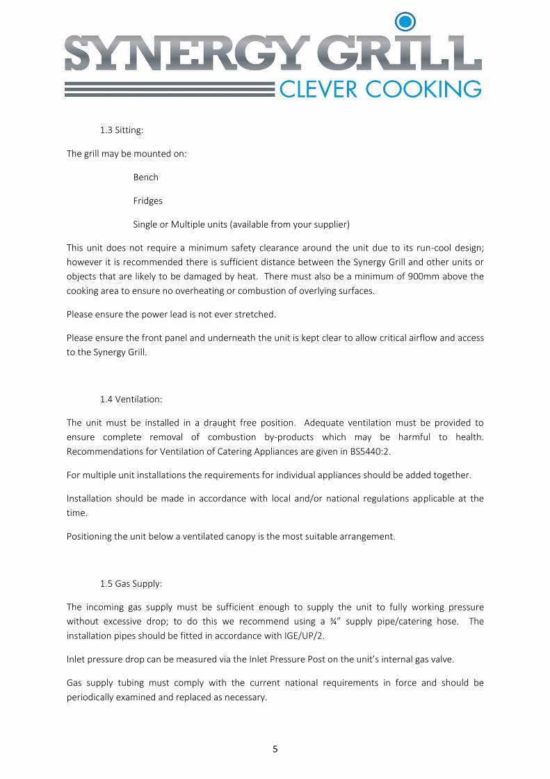
1.3 Sitting:
The grill may be mounted on:
Bench
Fridges
Single or Multiple units (available from your supplier)
This unit does not require a minimum safety clearance around the unit due to its run-cool design;
however it is recommended there is sufficient distance between the Synergy Grill and other units or
objects that are likely to be damaged by heat. There must also be a minimum of 900mm above the
cooking area to ensure no overheating or combustion of overlying surfaces.
Please ensure the power lead is not ever stretched.
Please ensure the front panel and underneath the unit is kept clear to allow critical airflow and access
to the Synergy Grill.
1.4 Ventilation:
The unit must be installed in a draught free position. Adequate ventilation must be provided to
ensure complete removal of combustion by-products which may be harmful to health.
Recommendations for Ventilation of Catering Appliances are given in BS5440:2.
For multiple unit installations the requirements for individual appliances should be added together.
Installation should be made in accordance with local and/or national regulations applicable at the
time.
Positioning the unit below a ventilated canopy is the most suitable arrangement.
1.5 Gas Supply:
The incoming gas supply must be sufficient enough to supply the unit to fully working pressure
without excessive drop; to do this we recommend using a ¾” supply pipe/catering hose. The
installation pipes should be fitted in accordance with IGE/UP/2.
Inlet pressure drop can be measured via the Inlet Pressure Post on the unit’s internal gas valve.
Gas supply tubing must comply with the current national requirements in force and should be
periodically examined and replaced as necessary.

6
An isolating cock must be located close to the appliance to allow a fast shut off during an emergency
or routine servicing.
1.6 Electrical Supply:
This unit is supplied via a 5A 3-pin plug at 240v.
This unit must be earthed or the appliance will not work. This unit relies on Flame Rectification to
detect the flame so a good earth allows the “path to ground through the flame” which is critical for
the appliance to work. Active Food Systems recommends extra earth bonding where possible.
1.7 Water Supply:
Not applicable for this appliance.
2 Commissioning
2.1 Testing and Purging:
Please make sure all air is purged from the pipes before checking pressures.
2.2 Checking Pressures:
A) To gain access to the internal gas valve please remove the top collar from the unit and
place to one side, you should now have access to four screws securing the front panel to
the unit. Remove these four screws and place the front panel underneath the appliance
being careful not to pull on any front panel wires.
B) Unscrew the Inlet Pressure Post with a 2.5mm Allen key and connect your manometer to
make sure the supply pressure is consistent with your gas type. Once happy with the
pressure, remove your manometer and tighten up the Inlet Pressure Post.
C) Unscrew the Outlet Pressure Post with a 2.5mm Allen key and connect your manometer.
7
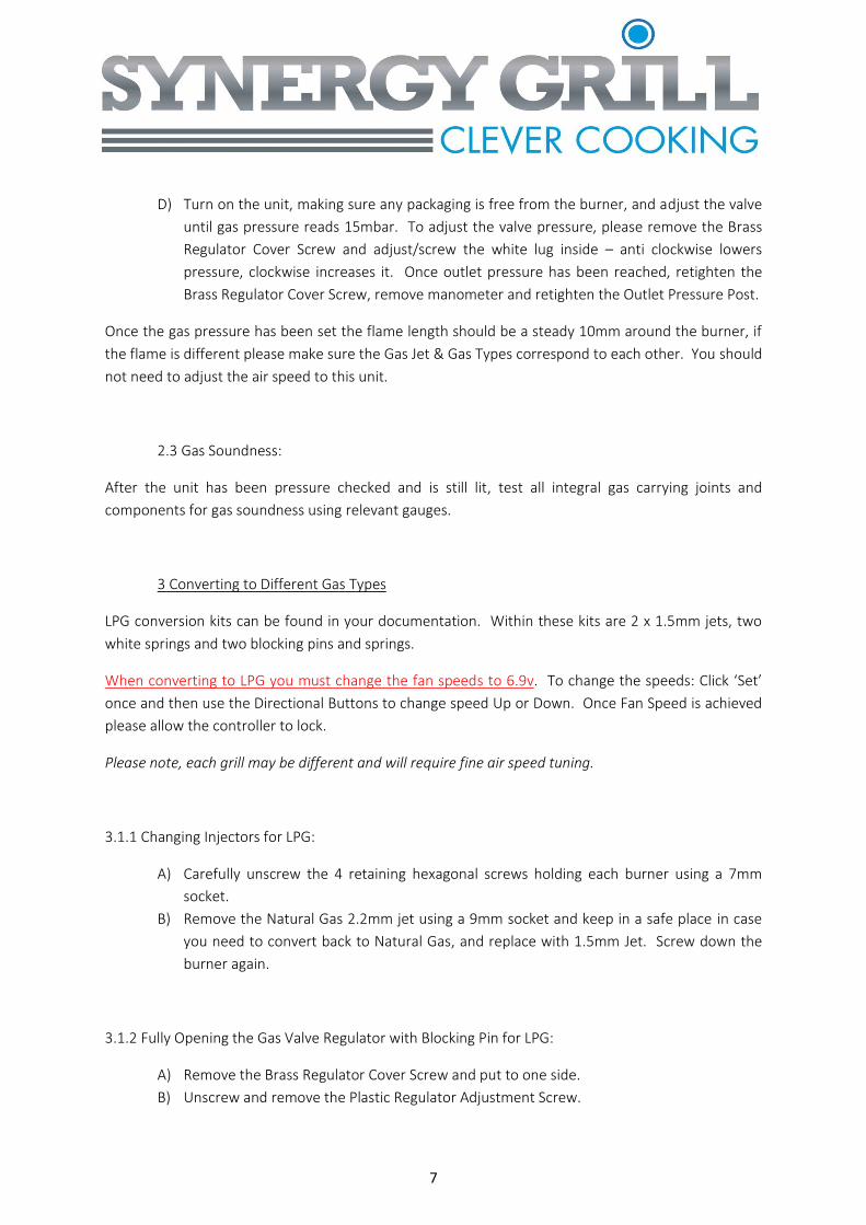
D) Turn on the unit, making sure any packaging is free from the burner, and adjust the valve
until gas pressure reads 15mbar. To adjust the valve pressure, please remove the Brass
Regulator Cover Screw and adjust/screw the white lug inside – anti clockwise lowers
pressure, clockwise increases it. Once outlet pressure has been reached, retighten the
Brass Regulator Cover Screw, remove manometer and retighten the Outlet Pressure Post.
Once the gas pressure has been set the flame length should be a steady 10mm around the burner, if
the flame is different please make sure the Gas Jet & Gas Types correspond to each other. You should
not need to adjust the air speed to this unit.
2.3 Gas Soundness:
After the unit has been pressure checked and is still lit, test all integral gas carrying joints and
components for gas soundness using relevant gauges.
3 Converting to Different Gas Types
LPG conversion kits can be found in your documentation. Within these kits are 2 x 1.5mm jets, two
white springs and two blocking pins and springs.
When converting to LPG you must change the fan speeds to 6.9v. To change the speeds: Click ‘Set’
once and then use the Directional Buttons to change speed Up or Down. Once Fan Speed is achieved
please allow the controller to lock.
Please note, each grill may be different and will require fine air speed tuning.
3.1.1 Changing Injectors for LPG:
A) Carefully unscrew the 4 retaining hexagonal screws holding each burner using a 7mm
socket.
B) Remove the Natural Gas 2.2mm jet using a 9mm socket and keep in a safe place in case
you need to convert back to Natural Gas, and replace with 1.5mm Jet. Screw down the
burner again.
3.1.2 Fully Opening the Gas Valve Regulator with Blocking Pin for LPG:
A) Remove the Brass Regulator Cover Screw and put to one side.
B) Unscrew and remove the Plastic Regulator Adjustment Screw.

8
C) Remove the Silver Spring (keep safe for converting back) and replace with White Spring
provided in the conversion kit.
D) Insert the Plastic Regulator Adjustment Screw and screw in all the way until you feel light
resistance – do not over tighten.
E) Take the Blocking Pin and Spring from your conversion kit and place the Blocking Pin
through the centre of the Spring. Now insert this through the centre of the Plastic
Regulator Adjustment Screw.
F) Replace the Brass Regulator Cover Screw.
3.1.3 LPG Data Plate:
Remove the LPG Data Plate from the documents supplied with this appliance and cover over the NAT
GAS Data Plate which can be found on this unit.
This unit is now ready to be used for G30, G31 &G30/G31 gas types.
3.2 How to Check the Appliances Internal Gas Valve is Fully Open/Out of Action:
The table provided in the Technical Information section (1.2) gives information on the supply
pressures of different gas types. Please ensure the valve is sufficiently open by using a manometer on
the Outlet Pressure Post pressure (with the burner lit) to check the reading is as close to the supply
pressure as possible. If the outlet pressure point has a significant drop in pressure from the inlet,
please go through step 3.1.2 again.
3.3 Converting to Natural Gas:
Natural Gas Jets (2.2mm) should have been kept in a safe place when you originally converted from
Natural Gas to LPG. If you have lost these parts please contact Active Food Systems.
If your appliance was originally requested as LPG and you wish to convert to Natural Gas, the relevant
conversion kit will be in your documentation.

9
When converting to Natural Gas you must change the fan speeds to 6.6v. To change the speeds: Click
‘Set’ once and then use the Directional Buttons to change speed Up or Down. Once Fan Speed is
achieved please allow the controller to lock.
Please note, each grill may be different and will require fine air speed tuning.
3.3.1 Changing Injectors for Natural Gas:
A) Carefully unscrew the 4 retaining hexagonal screws holding each burner using a 7mm
socket.
B) Remove the LPG 1.5mm jet using a 9mm socket and keep in a safe place in case you need
to convert back to LPG, and replace with 2.2mm Jet. Screw down the burner again.
3.3.2 Reinstating the Internal Gas Valve Regulator for Natural Gas:
A) Remove the Brass Regulator Cover Screw and put to one side.
B) Take out the Blocking Pin and Spring from the centre of the Plastic Regulator Adjustment
Screw and keep safe for when you need to convert back.
C) Unscrew and remove the Plastic Regulator Adjustment Screw.
D) Remove the White Spring (keep safe for converting back) and replace with Silver Spring
provided in the conversion kit.
E) Insert the Plastic Regulator Adjustment Screw and screw in about half way.
F) Connect your manometer to the Outlet Pressure Post (Follow steps 2.2 C & D) and set
burner to 15mbar.
G) Replace the Brass Regulator Cover Screw.
3.3.3 Nat Gas Data Plate:
Remove the Nat Gas Data Plate from the documents supplied with this appliance and cover over the
LPG Data Plate which can be found on this unit.
This unit is now ready to be used for G20 Gas type.

10
Synergy Grill 900
User & Engineer
Servicing &
Cleaning
Guide

11
Index:
Description Page Number/Section
Important Information 12
General Tools Required 12
Servicing Your Synergy Grill 13-15 / Section 4
Daily Cleaning 16 / Section 5
Warranty Registration 17
Installation Tips and Advice for Gas Installation Engineer 18
Section 4.1 Flame Dropping Out Through Service
Section 4.2 Changing an Ignitor
Section 4.3 Changing a Valve
Section 4.4 Changing a MicroGas Controller
Section 4.5 Burner & Injector Cleaning
Section 4.6 Any Other Problems
Section 5.1 End of Service Cleaning
Section 5.2 Daily Morning Cleaning
12
Important Information
All internal servicing work on this appliance is to be done via the front panel and by a certified
engineer. Please make sure access to the front panel and directly under the grill is always kept clear.
Please ensure the Gas Isolating Valve and Electrical Supply has been switched off before any service
work is carried out.
We recommend the appliance is cold before work is started. If possible please book your engineer in
for an AM service before the unit is switched on for greater ease of work. If the appliance has to be
worked on whilst it is still hot always use heat protective gloves when handling hot parts on and
below the cooking surface.
General Tools Required:
2.5mm Allen Key (Gas Pressure post)
3mm Allen Key (Ignitor)
Flat Headed Screwdriver (Brass Regulator Cover Screw & Plastic Regulator
Adjustment Screw)
Pozi 2 Screwdriver (General Screws Throughout)
Socket Set – 7 & 9mm (Burner Bolts & Jets)
Adjustable Spanner (internal Gas Valve Removal)
Manometer (Gas Pressures)
Wire Brush (Burner and Ignitor Cleaning)

13
4 Servicing Your Synergy Grill:
4.1 Flame Dropping Out Throughout Service:
If you have noticed the appliance Burner Flame has started dropping out during service, and has been
getting worse over time, you need to make sure the Flame Detector on the unit is free from debris.
This appliance relies on Flame Rectification to determine whether the Burner Flame is alight or not.
The internal MicroGas controller senses the required electrical circuit is completed via the ions in the
Burner Flame completing the circuit via a high resistive path to ground - the completed circuit keeps
the Internal Gas Valve open and the gas flowing. If no signal is received by the appliances internal
MicroGas Controller, the gas shuts off causing the system to lock out. The detection system will send
a False Signal back to the Microgas Controller if the electrode is contaminated with fats and oils.
To stop this simple problem we recommend a Daily Cleaning Regime of vacuuming the ceramics and
gently wiping away any debris from the electrode – try and keep the electrode and white ceramic
coating around the electrode as clean as possible. It may be easier to clean the ignitor once it has
been removed, please follow steps 4.2 to remove ignitor.
If you are still having problems with the Burner Flame dropping out during service after you have
thoroughly cleaned the Flame Detector please contact Active Food Systems.
4.2 Changing an Ignitor:
Remove the grill top panel to access the screws holding the panel in place (Figure 1).
Figure 1. Figure 2.
The ignitor can be removed by loosening the screw seen in Figure 2.
The replacement ignitor can be replaced and secured in the same way the faulty one was removed –
you must make sure the ignitor fits through the hole in the burner above.
If the reported problem persists, contact Active Food Systems.

14
4.3 Changing a Valve:
You should only have to change a valve if you: switch on your appliance, there is no ignition/spark
sequence and the red front panel light illuminates after ~20 seconds. If the ignition sequence begins
but no flame appears and then the red light comes on after three attempts please check: the gas
supply, nothing is blocking the Burner, the Air Speed is not too high.
Remove the grill top panel to access the screws holing the panel in place (Figure 1).
Please make sure the internal valve switch is ON. If the valve is OFF, please switch ON and try turning
the unit on again. If the grill now lights you do not need to change the valve.
Figure 3
Remove the valve by loosening the In, Out, and Injector pipe nuts and the two screws behind the
valve bracket (Figure 3). Once these have been undone please remove the faulty Gas Valve and insert
the replacement valve, reversing the above steps until all fixings are gas tight.
After the unit has been lit please test all integral gas carrying joints and components for gas
soundness using relevant gauges.
If the problem persists please contact Active Food Systems.
4.4 Changing a MicroGas Controller:
Changing a MicroGas controller should be attempted if you: switch the front Green Rocker Switch on
but it does not initiate the appliances fan to start up – if the front panel is not down at the time please
wait up to 20 seconds before you can hear the fan noise.
Remove the grill top panel to access the screws holding the panel in place (Figure 1).

15
Remove the MicroGas controller by disconnecting all wires and harnesses, and loosening the two
screws securing the controller (Figure 4). Before swapping out the whole MicroGas controller, firstly
perform a continuity test to make sure it is not just the 20x5 4A fuse that has blown.
Figure 4
The replacement MicroGas controller can be fitted in the reverse order the faulty controller was
removed.
If the problem persists please contact Active Food Systems.
4.5 Burner & Injector Cleaning:
Burners and Jets require periodic cleaning to ensure all ports and apertures are free from debris and
blockages. Failure to periodically clean these may result in Flame Detection and Heating problems.
Remove the burners (3.1.1) and vacuum around the jet to remove any debris which may have built up
over time. Whilst the Burner is removed please clear individual Burner Ports using a suitable metal
object. Should it become necessary to wash the burner, please ensure they are completely dry and
free from cleaning materials before re-fitting.
4.6 Any Other Problems:
If there are any other issues which need to be addressed that are not in this Servicing and Cleaning
Guide please contact Active Food Systems and we will be happy to run through any issues you may
have.

16
5.0 Daily Cleaning:
This appliance is designed to be user friendly when it comes to the Daily Cleaning; a quick clean in the
morning can save you a lot of time in the long run (4.1).
5.1 End of Service Cleaning:
A) Brush the cast iron cooking bars, either with your Synergy Grill Scraper Tool or wire brush,
and allow any food residue to fall into the ceramic cell below.
B) Keep the unit burning for a further 10-15 minutes to allow the fallen debris to ash-up
ready for morning cleaning.
5.2 Daily Morning Cleaning:
A) Remove the Cast Iron Cooking Bars using your Synergy Grill Lifting Tool and place to one
side.
B) Gently remove the Ceramic Ring and Cap from the Burner and place to one side.
C) Vacuum out any ash from the previous service.
D) Gently wipe the Ignitor/Flame Detector with a damp cloth to ensure all debris and residue
has been removed.
E) Replace the Ceramic Ring, Cap & Cast Iron Cooking Bars.
F) Give the unit a gentle wipe over.

17
Active Food Systems Ltd
Synergy House
Units 7 to 10 Greenewable Business Park
Station Lane
Offord Cluny
Cambridgeshire
PE19 5ZA
Warranty Registration:
Please Fill out this form and return to Active Food Systems to activate the warranty on your Synergy
Grill.
If we have to attend site after installation and we deem the problem to be caused by not following
the User & Engineer Installation Guide you may incur a charge.
Date Installed
Appliance Serial Number
Site Location
Engineer’s Gas Number
Burner Pressure is correct for stated
Gas Type
Name: Signature:

18
Installation Tips and Advice for Gas Installation Engineer:
This appliance requires a ¾” gas supply/catering hose.
Never use an in-line gas governor to set the pressure – regulation is achieved via the internal valve.
Always Earth-Bond this appliance.
Ensure electrical socket is in good condition.
Ensure the Outlet Pressure is as stated on the appliances Data Plate using a Manometer and 2.5mm
Allen Key – e.g. 15.0mbar for Natural Gas & 37mbar for Liquid Propane Gas whilst all other gas
kitchen appliances are running in the kitchen.
“Switch On and Walk Away” - This appliance has a Soft Start System which can take up to 40 seconds
before ignition and may take up to three attempts before the flame holds. Full fan speed should be
reached around 1 minute after appliance switch on.
Natural Gas Fan Speed is between 5.4 & 6.6 Volts
LPG Fan Speed is between 5.6 & 6.9 Volts
The Burner Flame should hold well against the burner and be covering the ignitor/flame sensor –
please adjust air speed as necessary. Too little air and the flame acts like a kitchen hob; too much and
heat is lost in corners.