
SYNERGY – PART I · 2016-02-05 · single- and multiphase systems. At all scales, from nano to...
103
M.Sc. Course on Process Intensification 03 December 2011 1 SYNERGY – PART I
Transcript of SYNERGY – PART I · 2016-02-05 · single- and multiphase systems. At all scales, from nano to...

M.Sc. Course on Process Intensification03 December 2011 1
SYNERGY –
PART I

M.Sc. Course on Process Intensification03 December 2011 2
Reminder…Fundamental principles and approaches of Process Intensification are applicable to any chemical process or operation. Intensification needs simultaneous addressing the four domains, as given below:
Domain Main focus Process Intensification concepts applied Motivation
Spatial Structured environment
Milli-
and microchannels; structured (catalyst) surfaces
well-defined geometry
creating maximum specific surface area at minimum energy expenses creating high mass and heat transfer rates precise mathematical description easy understanding, simple scale-up
Thermodynamic
Alternative forms and transfer mechanisms of energy
Electric and electromagnetic fields
manipulation of molecular orientation excitation of targeted molecules
selective, gradientless
and local energy supply
Functional Integration of functions/steps
Combination of alternative energy forms (e.g. electric and laser fields), combination of catalyst and energy source or energy-absorbing material.
synergistic effects better heat management increase of overall efficiency more compact equipment
Temporal
Timing of the events, introducing dynamics
Dynamic (pulsed) energy supply, millisecond contacting
controlled energy input utilizing resonance increased energy efficiency side reactions minimized
STRUCTURE
TIMESYNERGY
ENERGY

M.Sc. Course on Process Intensification03 December 2011 3
10-16 10-10 10--6 10-4 10-2 100 102 m
Molecular processes
Catalyst/reaction processes, particles, thin films Processing units
Processing plant/site
Hydrodynamics andtransport processes,single- and multiphase systems
At all scales, from nano
to macro
SYNERGY• small-scale synergy in catalysis• combining energy forms •
synergy in processing units –
multifunctional equipment and combined operations
• integrated reaction and mixing• integrated reaction and heat exchange
(to be continued in part II)

M.Sc. Course on Process Intensification03 December 2011 4
Small-scale synergy in catalysis

M.Sc. Course on Process Intensification03 December 2011 5
Catalytic
function
+ mass transport control function
Dautzenberg & Mukherjee, 2001
Homogeneous
Rh catalyst
encapsulated
by a porous
and hollow
silica
microsphere
causing
deliberate
diffusion-
limited
input of reactants
leading
to enhanced
product
selectivity.
Embryonic Growth Mature Aging

M.Sc. Course on Process Intensification03 December 2011 6
(F. Kapteijn
–
personal communication)
Catalytic
function
+ separation function
Membrane coated catalyst
ordinary Si-Al catalyst
Carbon molecular sievelayer (~ 0.5 nm pores)
TiO2 support
Pt catalyst
Silicalite-1 coating
TiO2 support
Pt catalyst
Silicalite-1 coating
Controlled feed to active sitesSelective feed to active sitesSelective product removal
Embryonic Growth Mature Aging

M.Sc. Course on Process Intensification03 December 2011 7
Catalytic
function
+ separation function
Agar, 1999
methanol
+ ammonium
monomethylamine
+ dimethylamine
+ trimethylamine
(MMA) (DMA)
(TMA)
catalyst
catalyst + membrane
Selectivity(MMA+DMA)/TMA
2
5
Embryonic Growth Mature Aging

M.Sc. Course on Process Intensification03 December 2011 8
Catalytic
function
+ separation
function: example
of reactive
adsorption
Dietrich et al., 2005
Reaction and adsorption in a multifunctional catalyst:
•
better removal of C due to higher concentrations
•
higher rate due to lower surface concentration of C
•
better adsorbent utilization (loading)
Embryonic Growth Mature Aging

M.Sc. Course on Process Intensification03 December 2011 9
Catalytic
function
+ separation
function: example
of reactive
adsorption
Dietrich et al., 2005; Kapil et al., 2008
catalyst core
adsorbent core
uniform mixture
Embryonic Growth Mature Aging
Simulated hydrogen yield 8.732 150.76 401.46

M.Sc. Course on Process Intensification03 December 2011 10
Combining energy forms

M.Sc. Course on Process Intensification03 December 2011 11
(A)- Orientation of a molecular beam of carbonyl sulphide molecules moving along the z-axis by a hexapole electric field (left) followed by their dissociation by a laser beam acting along the x-axis (from Rakitzis, et al, 2004); (B) - Probability plot of the molecular orientation of the OCS molecule; dotted arrows are proportional to the orientation probability of the OCS dipole moment along each direction.
(A)
(B)
Embryonic Growth Mature Aging
Combining
energy
forms: electric
field
+ laser beam

M.Sc. Course on Process Intensification03 December 2011 12
Combining
energy
forms: ultrasound
+ light
Additional
benefits
of US in photocatalytic
reactions:
• increased
local T and P• cleaning
and sweeping
of photocatalyst
(e.g., TiO2)• improved
mass transport towards
the catalyst• new solid
surfaces available
(due to fragmentation/deagglomeration
of catalyst)
• cavitation-induced
radical formation
Gogate and Pandit, 2004
Degradation
of formic
acid
Degradation
of trichlorophenol
Embryonic Growth Mature Aging

M.Sc. Course on Process Intensification03 December 2011 13
Combining
energy
forms: ultrasound
+ light
Gaplovsky
et al., 1997
Ultrasound
improves
photochemical
synthesis reactions
and alters
isomer
ratios
+US +US
Embryonic Growth Mature Aging

M.Sc. Course on Process Intensification03 December 2011 14
Combining
energy
forms: ultrasound
+ microwaves
Chemat, 2004
digestion of sunflower oil (yield>90%)
digestion of sesame oil
(yield>90%)
classical
microwave
microwave + ultrasound
50 min
40 min 50 min
35 min25 min
70 min
time intensification
(MW+US/class.)2 2
Embryonic Growth Mature Aging

M.Sc. Course on Process Intensification03 December 2011 15
Cravotto, 2007
Combining
energy
forms: ultrasound
+ microwaves
Embryonic Growth Mature Aging

M.Sc. Course on Process Intensification03 December 2011 16
Synergy
in processing
units
• Multifunctional reactors
• Hybrid separations

M.Sc. Course on Process Intensification03 December 2011 17
Synergy –
multiple functions
(after Tlatlik
and Schembecker, ARS-1, Dortmund 2000)
Function 1
Apparatus design
Function 2
Design criteria
on processing
unit level
difficult
to combine

M.Sc. Course on Process Intensification03 December 2011 18
Examples:
• integrated reaction and mixing
• integrated reaction and heat exchange
• integrated reaction and separation (reactive separation)
• integrated reaction and power generation (fuel cells)
• integrated reaction and phase transition (reactive extrusion)
• integrated reaction and comminution
Multifunctional reactors -
definition
Reactors, which alongside chemical conversion (and for the sake of it) integrate at least one more function (usually unit operation) that conventionally would have to be performed in a separate piece of equipment.

M.Sc. Course on Process Intensification03 December 2011 19
Integrated
reaction
and
mixing

M.Sc. Course on Process Intensification03 December 2011 20
Integration of (exothermic) reaction and mixing
(source: A. Green, in: Re-Engineering the Chemical Processing Plant, Marcel Dekker, 2003)
•
can be used as chemical reactors for carrying highly exothermic single-
or multiphase reactions
• mixer elements are made from cooling tubes
•
another option: shell-and-tube heat exchanger with static mixers inside the tubes
Embryonic Growth Mature Aging

M.Sc. Course on Process Intensification03 December 2011 21
vertical mode
Staging possibleCross-, co- and countercurrent
Monolithic stirrer reactor
Liquid phase reactionsHydroformylationFood processing
horizontal mode
F.Kapteijn et al., CATTECH 3(1999)24
Integration of catalytic reaction and mixing
Embryonic Growth Mature Aging

M.Sc. Course on Process Intensification03 December 2011 22
Monolithic Stirrer Reactor
I.Hoek
et al. Chem.Engng.Sci. 59 (2004) 4975-4981R.K.Edvinsson-Albers
et al. AIChE J. 44 (1998) 2459-2464
• Very suitable for biocatalysis• Retrofitting• Easy catalyst separation• Safety
Integration of catalytic reaction and mixing
Embryonic Growth Mature Aging

M.Sc. Course on Process Intensification03 December 2011 23
Integrated
reaction
and heat
exchange

M.Sc. Course on Process Intensification03 December 2011 24
Standard parameters of commercial stirred tanks
Heat transfer area –
thermal problem in stirred-tank reactors
The bigger, the worse

M.Sc. Course on Process Intensification03 December 2011 25
• Heat
that
could
be
removed
in a batch reactor, with
an optimistic
overall
heat
transfer
coefficient U= 500 W.m-2.K-1
Volume (m3) 1.10-3 1.10-2 0,1 1
Diameter (m) 0,08 0,2 0,4 0,9
Height (m) 0,2 0,3 0,8 1,4
A (m2) 0,055 0,22 1,13 4,6
Qmax /V (kW.m-3) 1200 500 250 100
tc (s) 230 560 1120 2800
tc mthio
Mthio N
thio
maxwithN
thio
max
Qmax
Hr
2 Na2
S2
O3
+ 4H2
O2
Na2
S3
O6
+ Na2
SO4
+ 4H2
OΔHr
= -586.2 kJ.mol-1
Na2
S2
O3
A typical
exothermal
reaction
test: sodium thiosulfate oxidation
Heat transfer area –
thermal problem in stirred-tank reactors
C. Gourdon, Rhodia
Sustainability Conference, 2008

M.Sc. Course on Process Intensification03 December 2011 26
Why integrate?• Better energy management (less losses)• Higher yields/selectivities• Less investment (compacter equipment)• Longer catalyst lifetime (less severe conditions)• Safety reasons
– better controlability
of reaction– smaller volume
…
Integration of reaction and heat exchange

M.Sc. Course on Process Intensification03 December 2011 27
• Inputs• Contacting pattern• Cumulative kinetics
(+ thermodynamics)
Factors influencing reactor performance
(source: D. Agar, in: Re-Engineering the Chemical Processing Plant, Marcel Dekker, 2003)

M.Sc. Course on Process Intensification03 December 2011 28
(source: D. Agar, in: Re-Engineering the Chemical Processing Plant, Marcel Dekker, 2003)
Factors influencing reactor performance
Reaction kinetics depend on local:• Temperatures
• Concentrations
• Catalytic activities
i.e. ri
(Ac
, C, T)
Reactor performance can be regulated via:• Temperature profile
• Concentration profiles
• Activity distribution

M.Sc. Course on Process Intensification03 December 2011 29
PI possibilities
(source: D. Agar, in: Re-Engineering the Chemical Processing Plant, Marcel Dekker, 2003)
Strategies for manipulating temperature profiles
• Recuperative heat transfer
• Regenerative heat transfer
• Convective heat transfer
• Reactive heat transfer

M.Sc. Course on Process Intensification03 December 2011 30
Strategies for manipulation of temperature profiles in the reactor
A. Convectionaddition or withdrawal of sidestreams
e.g. cold-shot reactor
T
z
(source: D. Agar, in: Re-Engineering the Chemical Processing Plant, Marcel Dekker, 2003)

M.Sc. Course on Process Intensification03 December 2011 31
B. Recuperation
spatial segregation between reactionmedium & material/heat-sink/sourcee.g. multitubular
reactor
T
z
(source: D. Agar, in: Re-Engineering the Chemical Processing Plant, Marcel Dekker, 2003)
Strategies for manipulation of temperature profiles in the reactor
PI focus: heat transfer coefficients, heat exchange specific surface areas

M.Sc. Course on Process Intensification03 December 2011 32
(source: D. Agar, in: Re-Engineering the Chemical Processing Plant, Marcel Dekker, 2003)
C. Regenerationchronological segregation betweenreaction medium & material/heat -sink/sourcee.g. reverse flow reactor
T
z
Strategies for manipulation of temperature profiles in the reactor
PI focus: feasibility windows, system dynamics and control

M.Sc. Course on Process Intensification03 December 2011 33
D. Reactiondirect coupling of main reactionwith thermally/materially compatible supplementary reactione.g. oxydehydrogenation
T
z
C DA B
(source: D. Agar, in: Re-Engineering the Chemical Processing Plant, Marcel Dekker, 2003)
Strategies for manipulation of temperature profiles in the reactor
PI focus: feasibility windows, system dynamics and control
M.Sc. Course on Process Intensification03 December 2011 34
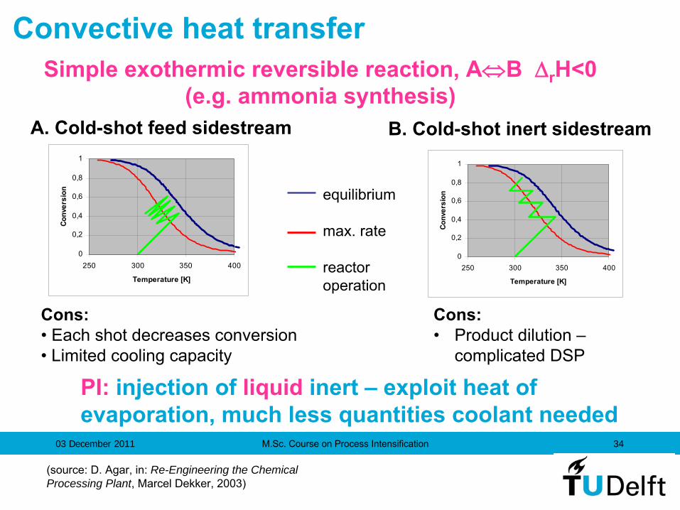
Simple exothermic
reversible reaction, AB r
H<0(e.g. ammonia
synthesis)
0
0,2
0,4
0,6
0,8
1
250 300 350 400
Temperature [K]
Conv
ersi
on
B. Cold-shot
inert
sidestream
0
0,2
0,4
0,6
0,8
1
250 300 350 400
Temperature [K]
Conv
ersi
on
A. Cold-shot
feed
sidestream
equilibrium
max. rate
reactoroperation
Cons:• Each
shot
decreases
conversion• Limited
cooling
capacity
Cons:•
Product
dilution
–
complicated
DSP
PI:
injection
of liquid
inert – exploit heat of evaporation, much
less
quantities
coolant
needed
Convective heat transfer
(source: D. Agar, in: Re-Engineering the Chemical Processing Plant, Marcel Dekker, 2003)

M.Sc. Course on Process Intensification03 December 2011 35
Unwanted temperature maxima arising in tubular reactorswith exothermic reactions due to heat transfer limitations
Heat exchange area (A)~ 100 m²/m³Heat transfer coefficient (h)~ 100 W/m²K
Hot-spot adversely effects:- conversion-
selectivity-
safety-
catalyst lifetime-
choice of reactor materials
30K
100K
25 mm
25 000 tubes
Reactor feed
Coolant
(source: D. Agar, in: Re-Engineering the Chemical Processing Plant, Marcel Dekker, 2003)
Hot-spots –
thermal problem in catalytic reactors

M.Sc. Course on Process Intensification03 December 2011 36
Improved co-ordination between the rates of heat generation & heat removal in reactor
-
diminish reaction rate and/or catalyst activity (defensive)• e.g. slow-down reactants dosing, dilute the system/catalyst
-
enlarge heat exchange surface
(partial solution)• e.g. Linde-reactor
-
raise heat transfer coefficient
(partial solution)• e.g. Fluidised bed
-
increase both A & h (PI solution)• Microreactor•• Millireactor
(source: D. Agar, in: Re-Engineering the Chemical Processing Plant, Marcel Dekker, 2003)
Eliminating heat exchange problems in reactors

M.Sc. Course on Process Intensification03 December 2011 37
Reaction is distributed more evenly over the cooling surface+ simple procedure
+
exact activity profile not critical
+
significant selectivity improvement of ~1%
–
much larger reactor & ΔP necessary
(source: D. Agar, in: Re-Engineering the Chemical Processing Plant, Marcel Dekker, 2003)
Hot-spots -
eliminatingImproved co-ordination of reaction & coolingusing Catalyst dilution
with inert

M.Sc. Course on Process Intensification03 December 2011 38
+ good isothermal behaviour (20K)
+ slightly higher heat transfer coefficients(h~150 W/m²K)
– complex reactor construction
– temperature limited to <550K byboiling water coolant
– catalyst removal?
Steam
Gas inletWaterrecycle
Gas outletFeed water
Increased specific heat exchange surface of convoluted coolant tube coil in catalyst bed
(source: D. Agar, in: Re-Engineering the Chemical Processing Plant, Marcel Dekker, 2003)
Hot-spots -
eliminatingImproved co-ordination of reaction & cooling using a
Linde™
reactor

M.Sc. Course on Process Intensification03 December 2011 39
Increased heat transfer coefficients due to efficient convective-regenerative particle transport mechanism
+ excellent isothermal behaviour (h~600 W/m²K)
+ higher degree of catalyst utilisation
+ facile catalyst regeneration
– very mechanically resilient catalyst needed
– limited hydrodynamic loading range
– undesirable backmixing
– scale-up?
Improved co-ordination of reaction & cooling using a Fluidised bed
reactor
(source: D. Agar, in: Re-Engineering the Chemical Processing Plant, Marcel Dekker, 2003)
Hot-spots -
eliminating
M.Sc. Course on Process Intensification03 December 2011 40
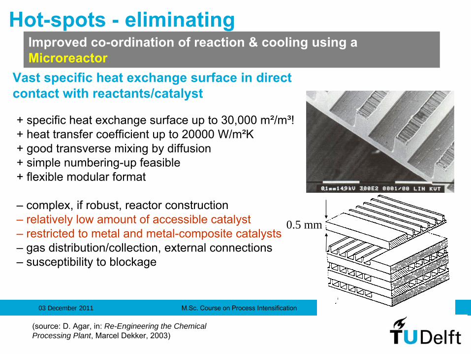
+ specific heat exchange surface up to 30,000 m²/m³!+ heat transfer coefficient up to 20000 W/m²K+ good transverse mixing by diffusion + simple numbering-up feasible+ flexible modular format
– complex, if robust, reactor construction– relatively low amount of accessible catalyst– restricted to metal and metal-composite catalysts– gas distribution/collection, external connections– susceptibility to blockage
0.5 mm
Vast specific heat exchange surface in direct contact with reactants/catalyst
(source: D. Agar, in: Re-Engineering the Chemical Processing Plant, Marcel Dekker, 2003)
Improved co-ordination of reaction & cooling using a
Microreactor
Hot-spots -
eliminating

M.Sc. Course on Process Intensification03 December 2011 41
• the chemical processes occurring at the active sites impose an upperlimit on reaction rate (~1mol/gcat
s*) and heat generation (~500kW/m³)
•
for chemically limited kinetics, acceptable temperature gradients of ca. 2K and thermal conductivity of typically 1 W/mK, a specific heat exchange surface of ~1,000 m²/m³
is usually adequate to ensure rapid heat removal.
Microreactors
offer unnecessarily excessive
heat exchange surface
reactor dimensions of 1-5mm,i.e. ‘Millireactors’
(or HEX reactors)* for typical industrial synthesis reactions 0,01
0,1
1
10
100
0,001 0,01 0,1 1 10 100 1000
k [1/s]
d [m
m]
Da
=2NTU =100Nu = 3,7a =10-5
m²/s
(source: D. Agar, in: Re-Engineering the Chemical Processing Plant, Marcel Dekker, 2003)(source: D. Agar, in: Re-Engineering the Chemical Processing Plant, Marcel Dekker, 2003)
Limitations of catalytic activity

M.Sc. Course on Process Intensification03 December 2011 42
•
structure & scale similarto plate heat exchanger
•
porous catalyst plates1-2 mm thick
•
alternating plain & laser-engraved profile plates
•
plates stacked and ‘cemented’
•
cocurrent, countercurrent& X-flow cooling possible
•
combination of modulesfor complex T-profiles
(source: D. Agar, in: Re-Engineering the Chemical Processing Plant, Marcel Dekker, 2003)
Catalytic plate millireactors
(HEX reactors)
Embryonic Growth Mature Aging

M.Sc. Course on Process Intensification03 December 2011 43
• well-defined laminar flow conditions
• amenable to Computational fluid dynamic modelling
• deliberate local turbulence to yield plug flow behaviour
• channel structure for uniform gas & coolant distribution
(source: D. Agar, in: Re-Engineering the Chemical Processing Plant, Marcel Dekker, 2003)
Catalytic plate millireactors
(HEX reactors)
Embryonic Growth Mature Aging

M.Sc. Course on Process Intensification03 December 2011 44
BENEFITS:higher yieldsimproved product purityvery good reaction control
continuous productionlow running costslow capital costs -
small planthigh pressure capability
no thermal runaways
APPLICATIONS (examples):nitrationazo
couplinghalogenationhydrogenationoxidationsulfonation
Marbond
reactor (Chart Heat Exchangers) -with heat transfer area up to 1000 m/m2 3
ECN reactor with washcoated
catalyst
Embryonic Growth Mature Aging
Heat exchanger (milli-) reactors

M.Sc. Course on Process Intensification03 December 2011 45
Hickson
& Welch process (two-stage catalyzed oxidation of a thioether
to a sulfone):
•
reaction time reduced from 18 hrs to 15 mins
ICI Acrylics process:
•
by-product formation decreased from 2% to 0.5% (simulation)
Embryonic Growth Mature Aging
Heat exchanger (milli-) reactors

M.Sc. Course on Process Intensification03 December 2011 46
Alfa Laval -
the Plate Reactor
Concept
Rea
ctor
vol
ume
Rea
ctor
vol
ume
Cooling or HeatingPlates
A
B
ANGE
Embryonic Growth Mature Aging
Courtesy: Alfa Laval

M.Sc. Course on Process Intensification03 December 2011 47
Channel Plate
Full Reactor
Components
Based on Plates
1 – 10 l/hrLab Scale
Alfa Laval -
the Plate Reactor
ConceptANGE
Embryonic Growth Mature Aging

M.Sc. Course on Process Intensification03 December 2011 48
3 Plates Volume
1.4 litres
90 sec residence time at 50 l/hr
Pilot Scale
Initial Target : 1 –
2 m3/hr
Production Scale
ANGE
Embryonic Growth Mature Aging
Alfa Laval -
the Plate Reactor
Concept
M.Sc. Course on Process Intensification03 December 2011 49
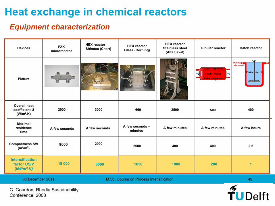
120010001650Intensification
factor US/V (kW/m3.K)
2.54004002500Compactness
S/V (m²/m3)
A few hoursA few minutesA few minutesA few seconds Maximal
residencetime
4005002500660Overall heat coefficient U
(W/m².K)
Picture
Batch reactorTubular
reactorHEX reactor
Stainless
steel
(Alfa Laval)
HEX reactorGlass (Corning)Devices
Heat
exchange in chemical
reactorsEquipment characterization
Fluide RFluide réactif
Fluidecaloporteur
Fluide CaloporteurFluide Réactif
Fluide Caloporteur
Fluide réactif
Fluide caloporteur
Fluide caloporteur
HEX reactorShimtec
(Chart)
3000
A few seconds –minutes
2000
6000
FZKmicroreactor
A few seconds
2000
9000
18 000
C. Gourdon, Rhodia
Sustainability Conference, 2008

M.Sc. Course on Process Intensification03 December 2011 50
Prototype
Sandwich plates
Inox 316L
Gaskets Viton®
Connections
Swagelok (316L)
SiC (brazed reactionplates)
ANGE
Embryonic Growth Mature Aging
C. Gourdon, Rhodia
Sustainability Conference, 2008
Importance of the material and of the design
Heat exchanger (milli-) reactors

M.Sc. Course on Process Intensification03 December 2011 51
SiC Steel Glass
(20°C)W.m-1.K-1
180 16 1
Cp (20°C)J.kg-1.K-1
680 500 800
(kg.m-3) 3210 7900 2600
Effusivity b20000 8000 1500
Larger b = Surface Temperature imposed by the material and higher dynamics
b = (. Cp. )1/2
Importance of the material and of the design
Heat exchanger (milli-) reactors
C. Gourdon, Rhodia
Sustainability Conference, 2008
ANGE
Embryonic Growth Mature Aging

M.Sc. Course on Process Intensification03 December 2011 52
Importance of the material and of the design
12001000165014 000Intensification
factor US/V (kW/m3.K)
2.540040025002000Compactness
S/V (m²/m3)
A few hoursA few minutesA few minutesA few seconds -
minutesA few minutesMaximal
residencetime
40050025006607000Overall heat coefficient U
(W/m².K)
Picture
Batch reactorTubular
reactorHEX reactor
Stainless
steel
(Alfa Laval)
HEX reactor
Glass (Corning)
HEX reactor
SiC(Boostec/LGC)Devices
Fluide RFluide réactif
Fluidecaloporteur
Fluide CaloporteurFluide Réactif
Fluide Caloporteur
Fluide réactif
Fluide caloporteur
Fluide caloporteur
C. Gourdon, Rhodia
Sustainability Conference, 2008
Heat exchanger (milli-) reactors

M.Sc. Course on Process Intensification03 December 2011 53
Helix reactor (TNO Institute)
• intensive heat transfer
• plug-flow characteristics
• good radial mixing Straight pipe (inlet)
Straight pipe (outlet)
Helix reactor (outlet)
Heat exchanger (milli-) reactors –
other concepts
Embryonic Growth Mature Aging

M.Sc. Course on Process Intensification03 December 2011 54
Pilot-scale tests with an industrial highly exothermic process:
•
4x increase of production capacity at 3x less volume
• 75% less energy
• 30% less waste
• variable costs 3x lower
• full pay-back 1 year less
Helix reactor (TNO Institute)
Heat exchanger (milli-) reactors –
other concepts
Embryonic Growth Mature Aging

M.Sc. Course on Process Intensification03 December 2011 55
Evaluation:•
cost-effective alternative to both conventional & microreactor
technology for industrial applications
•
based on proven catalyst materials and state-of-the-art fabrication techniques
•
non-specific, generally applicable concept
•
low development costs, short time-to-market
•
straightforward modelling, reliable scale-up
•
flexible and operationally robust reactor configuration
•
compatible with catalyst regeneration, recycling or disposal
(source: D. Agar, in: Re-Engineering the Chemical Processing Plant, Marcel Dekker, 2003)
Heat exchanger (milli-) reactors

M.Sc. Course on Process Intensification03 December 2011 56
RFlow in Flow out1 2
Catalyst
(a)
RFlow in Flow out1 4
2'
2 3'
3
Catalyst
(b)
Regenerative heat transfer
Reverse-flow reactors –
will be discussed in TIME lecture
Embryonic Growth Mature Aging

M.Sc. Course on Process Intensification03 December 2011 57
Reaction
+ Desorption
Heat
of reaction
consumed
bydesorption
of inert
(
) fromloaded
adsorbent
in mixedcatalyst
+ adsorbent
fixed-bed
Adiabatic
cyclic
reactor
operation
Heat
of reaction
consumed
bydesorption
of inert
(
) fromloaded
adsorbent
in mixedcatalyst
+ adsorbent
fixed-bed
Adiabatic
cyclic
reactor
operation
Adsorption
tcycle
CO + ½
O2
CO2
Principle: enhanced, ‘active’
regenerative heat removal
M. Franke
(2001) Diploma thesis, University of Dortmund
(source: D. Agar, in: Re-Engineering the Chemical Processing Plant, Marcel Dekker, 2003)
Desorptive
cooling
Embryonic Growth Mature Aging

M.Sc. Course on Process Intensification03 December 2011 58
Pros and Cons:
high intensity cooling system
no heat exchange surface in reactor
self-regulating heat uptake process
customised heat removal via adsorbent distribution
– unsteady-state operation
– lower space time yields
– compatibility of adsorption & reaction systems
(source: D. Agar, in: Re-Engineering the Chemical Processing Plant, Marcel Dekker, 2003)
Desorptive
cooling
Embryonic Growth Mature Aging
59
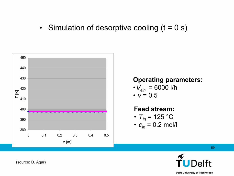
• Simulation of desorptive
cooling
(t = 0 s)
Feed
stream:•
Tin = 125 °C•
cin = 0.2 mol/l
Operating
parameters:•
= 6000 l/h•
v = 0.5einV
380
390
400
410
420
430
440
450
0 0,1 0,2 0,3 0,4 0,5
z [m]
T [K
]
(source: D. Agar)

60
380
390
400
410
420
430
440
450
0 0,1 0,2 0,3 0,4 0,5
z [m]
T [K
]
•Simulation of desorptive
cooling
(t = 0 s)
Feed
stream:•
Tin = 125 °C•
cin = 0.2 mol/l
Operating
parameters:•
= 6000 l/h•
v = 0.5einV
(source: D. Agar)

61
380
390
400
410
420
430
440
450
0 0,1 0,2 0,3 0,4 0,5
z [m]
T [K
]
•Simulation of desorptive
cooling
(t = 50 s)
Feed
stream:•
Tin = 125 °C•
cin = 0.2 mol/l
Operating
parameters:•
= 6000 l/h•
v = 0.5einV
(source: D. Agar)

62
380
390
400
410
420
430
440
450
0 0,1 0,2 0,3 0,4 0,5
z [m]
T [K
]
•Simulation of desorptive
cooling
(t = 100 s)
Feed
stream:•
Tin = 125 °C•
cin = 0.2 mol/l
Operating
parameters:•
= 6000 l/h•
v = 0.5einV
(source: D. Agar)

63
380
390
400
410
420
430
440
450
0 0,1 0,2 0,3 0,4 0,5
z [m]
T [K
]
•Simulation of desorptive
cooling
(t = 150 s)
Feed
stream:•
Tin = 125 °C•
cin = 0.2 mol/l
Operating
parameters:•
= 6000 l/h•
v = 0.5einV
(source: D. Agar)

64
380
390
400
410
420
430
440
450
0 0,1 0,2 0,3 0,4 0,5
z [m]
T [K
]
•Simulation of desorptive
cooling
(t = 200 s)
Feed
stream:•
Tin = 125 °C•
cin = 0.2 mol/l
Operating
parameters:•
= 6000 l/h•
v = 0.5einV
(source: D. Agar)

65
380
390
400
410
420
430
440
450
0 0,1 0,2 0,3 0,4 0,5
z [m]
T [K
]
•Simulation of desorptive
cooling
(t = 250 s)
Feed
stream:•
Tin = 125 °C•
cin = 0.2 mol/l
Operating
parameters:•
= 6000 l/h•
v = 0.5einV
(source: D. Agar)

66
380
390
400
410
420
430
440
450
0 0,1 0,2 0,3 0,4 0,5
z [m]
T [K
]
•Simulation of desorptive
cooling
(t = 300 s)
Feed
stream:•
Tin = 125 °C•
cin = 0.2 mol/l
Operating
parameters:•
= 6000 l/h•
v = 0.5einV
(source: D. Agar)

67
380
390
400
410
420
430
440
450
0 0,1 0,2 0,3 0,4 0,5
z [m]
T [K
]
•Simulation of desorptive
cooling
(t = 350 s)
Feed
stream:•
Tin = 125 °C•
cin = 0.2 mol/l
Operating
parameters:•
= 6000 l/h•
v = 0.5einV
(source: D. Agar)

68
380
390
400
410
420
430
440
450
0 0,1 0,2 0,3 0,4 0,5
z [m]
T [K
]
•Simulation of desorptive
cooling
(t = 400 s)
Feed
stream:•
Tin = 125 °C•
cin = 0.2 mol/l
Operating
parameters:•
= 6000 l/h•
v = 0.5einV
(source: D. Agar)

69
380
390
400
410
420
430
440
450
0 0,1 0,2 0,3 0,4 0,5
z [m]
T [K
]
•Simulation of desorptive
cooling
(t = 450 s)
Feed
stream:•
Tin = 125 °C•
cin = 0.2 mol/l
Operating
parameters:•
= 6000 l/h•
v = 0.5einV
(source: D. Agar)

70
380
390
400
410
420
430
440
450
0 0,1 0,2 0,3 0,4 0,5
z [m]
T [K
]
•Simulation of desorptive
cooling
(t = 500 s)
Feed
stream:•
Tin = 125 °C•
cin = 0.2 mol/l
Operating
parameters:•
= 6000 l/h•
v = 0.5einV
(source: D. Agar)

71
380
390
400
410
420
430
440
450
0 0,1 0,2 0,3 0,4 0,5
z [m]
T [K
]
•Simulation of desorptive
cooling
(t = 550 s)
Feed
stream:•
Tin = 125 °C•
cin = 0.2 mol/l
Operating
parameters:•
= 6000 l/h•
v = 0.5einV
(source: D. Agar)

72
380
390
400
410
420
430
440
450
0 0,1 0,2 0,3 0,4 0,5
z [m]
T [K
]
•Simulation of desorptive
cooling
(t = 600 s)
Feed
stream:•
Tin = 125 °C•
cin = 0.2 mol/l
Operating
parameters:•
= 6000 l/h•
v = 0.5einV
(source: D. Agar)

73
380
390
400
410
420
430
440
450
0 0,1 0,2 0,3 0,4 0,5
z [m]
T [K
]
•Simulation of desorptive
cooling
(t = 650 s)
Feed
stream:•
Tin = 125 °C•
cin = 0.2 mol/l
Operating
parameters:•
= 6000 l/h•
v = 0.5einV
(source: D. Agar)

74
380
390
400
410
420
430
440
450
0 0,1 0,2 0,3 0,4 0,5
z [m]
T [K
]
•Simulation of desorptive
cooling
(t = 700 s)
Feed
stream:•
Tin = 125 °C•
cin = 0.2 mol/l
Operating
parameters:•
= 6000 l/h•
v = 0.5einV
(source: D. Agar)

75
380
390
400
410
420
430
440
450
0 0,1 0,2 0,3 0,4 0,5
z [m]
T [K
]
•Simulation of desorptive
cooling
(t = 750 s)
Feed
stream:•
Tin = 125 °C•
cin = 0.2 mol/l
Operating
parameters:•
= 6000 l/h•
v = 0.5einV
(source: D. Agar)

76
380
390
400
410
420
430
440
450
0 0,1 0,2 0,3 0,4 0,5
z [m]
T [K
]
•Simulation of desorptive
cooling
(t = 800 s)
Feed
stream:•
Tin = 125 °C•
cin = 0.2 mol/l
Operating
parameters:•
= 6000 l/h•
v = 0.5einV
(source: D. Agar)

77
380
390
400
410
420
430
440
450
0 0,1 0,2 0,3 0,4 0,5
z [m]
T [K
]
•Simulation of desorptive
cooling
(t = 850 s)
Feed
stream:•
Tin = 125 °C•
cin = 0.2 mol/l
Operating
parameters:•
= 6000 l/h•
v = 0.5einV
(source: D. Agar)
78
380
390
400
410
420
430
440
450
0 0,1 0,2 0,3 0,4 0,5
z [m]
T [K
]
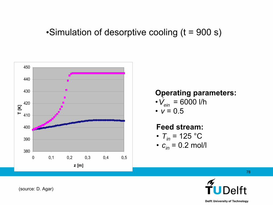
•Simulation of desorptive
cooling
(t = 900 s)
Feed
stream:•
Tin = 125 °C•
cin = 0.2 mol/l
Operating
parameters:•
= 6000 l/h•
v = 0.5einV
(source: D. Agar)

79
380
390
400
410
420
430
440
450
0 0,1 0,2 0,3 0,4 0,5
z [m]
T [K
]
•Simulation of desorptive
cooling
(t = 950 s)
Feed
stream:•
Tin = 125 °C•
cin = 0.2 mol/l
Operating
parameters:•
= 6000 l/h•
v = 0.5einV
(source: D. Agar)

80
380
390
400
410
420
430
440
450
0 0,1 0,2 0,3 0,4 0,5
z [m]
T [K
]
•Simulation of desorptive
cooling
(t = 1000 s)
Feed
stream:•
Tin = 125 °C•
cin = 0.2 mol/l
Operating
parameters:•
= 6000 l/h•
v = 0.5einV
(source: D. Agar)

81
380
390
400
410
420
430
440
450
0 0,1 0,2 0,3 0,4 0,5
z [m]
T [K
]
•Simulation of desorptive
cooling
(t = 1050 s)
Feed
stream:•
Tin = 125 °C•
cin = 0.2 mol/l
Operating
parameters:•
= 6000 l/h•
v = 0.5einV
(source: D. Agar)

82
380
390
400
410
420
430
440
450
0 0,1 0,2 0,3 0,4 0,5
z [m]
T [K
]
•Simulation of desorptive
cooling
(t = 1100 s)
Feed
stream:•
Tin = 125 °C•
cin = 0.2 mol/l
Operating
parameters:•
= 6000 l/h•
v = 0.5einV
(source: D. Agar)

83
380
390
400
410
420
430
440
450
0 0,1 0,2 0,3 0,4 0,5
z [m]
T [K
]
•Simulation of desorptive
cooling
(t = 1150 s)
Feed
stream:•
Tin = 125 °C•
cin = 0.2 mol/l
Operating
parameters:•
= 6000 l/h•
v = 0.5einV
(source: D. Agar)

84
380
390
400
410
420
430
440
450
0 0,1 0,2 0,3 0,4 0,5
z [m]
T [K
]
•Simulation of desorptive
cooling
(t = 1200 s)
Feed
stream:•
Tin = 125 °C•
cin = 0.2 mol/l
Operating
parameters:•
= 6000 l/h•
v = 0.5einV
(source: D. Agar)

85
380
390
400
410
420
430
440
450
0 0,1 0,2 0,3 0,4 0,5
z [m]
T [K
]
•Simulation of desorptive
cooling
(t = 1250 s)
Feed
stream:•
Tin = 125 °C•
cin = 0.2 mol/l
Operating
parameters:•
= 6000 l/h•
v = 0.5einV
(source: D. Agar)

86
380
390
400
410
420
430
440
450
0 0,1 0,2 0,3 0,4 0,5
z [m]
T [K
]
•Simulation of desorptive
cooling
(t = 1350 s)
Feed
stream:•
Tin = 125 °C•
cin = 0.2 mol/l
Operating
parameters:•
= 6000 l/h•
v = 0.5einV
(source: D. Agar)

87
380
390
400
410
420
430
440
450
0 0,1 0,2 0,3 0,4 0,5
z [m]
T [K
]
•Simulation of desorptive
cooling
(t = 1400 s)
Feed
stream:•
Tin = 125 °C•
cin = 0.2 mol/l
Operating
parameters:•
= 6000 l/h•
v = 0.5einV
(source: D. Agar)

88
380
390
400
410
420
430
440
450
0 0,1 0,2 0,3 0,4 0,5
z [m]
T [K
]
•Simulation of desorptive
cooling
(t = 1450 s)
Feed
stream:•
Tin = 125 °C•
cin = 0.2 mol/l
Operating
parameters:•
= 6000 l/h•
v = 0.5einV
(source: D. Agar)

89
380
390
400
410
420
430
440
450
0 0,1 0,2 0,3 0,4 0,5
z [m]
T [K
]
•Simulation of desorptive
cooling
(t = 1500 s)
Feed
stream:•
Tin = 125 °C•
cin = 0.2 mol/l
Operating
parameters:•
= 6000 l/h•
v = 0.5einV
(source: D. Agar)

90
380
390
400
410
420
430
440
450
0 0,1 0,2 0,3 0,4 0,5
z [m]
T [K
]
•Simulation of desorptive
cooling
(t = 1550 s)
Feed
stream:•
Tin = 125 °C•
cin = 0.2 mol/l
Operating
parameters:•
= 6000 l/h•
v = 0.5einV
(source: D. Agar)

91
380
390
400
410
420
430
440
450
0 0,1 0,2 0,3 0,4 0,5
z [m]
T [K
]
•Simulation of desorptive
cooling
(t = 1600 s)
Feed
stream:•
Tin = 125 °C•
cin = 0.2 mol/l
Operating
parameters:•
= 6000 l/h•
v = 0.5einV
(source: D. Agar)

92
380
390
400
410
420
430
440
450
0 0,1 0,2 0,3 0,4 0,5
z [m]
T [K
]
•Simulation of desorptive
cooling
(t = 1650 s)
Feed
stream:•
Tin = 125 °C•
cin = 0.2 mol/l
Operating
parameters:•
= 6000 l/h•
v = 0.5einV
(source: D. Agar)

93
380
390
400
410
420
430
440
450
0 0,1 0,2 0,3 0,4 0,5
z [m]
T [K
]
•Simulation of desorptive
cooling
(t = 1700 s)
Feed
stream:•
Tin = 125 °C•
cin = 0.2 mol/l
Operating
parameters:•
= 6000 l/h•
v = 0.5einV
(source: D. Agar)

94
380
390
400
410
420
430
440
450
0 0,1 0,2 0,3 0,4 0,5
z [m]
T [K
]
•Simulation of desorptive
cooling
(t = 1750 s)
Feed
stream:•
Tin = 125 °C•
cin = 0.2 mol/l
Operating
parameters:•
= 6000 l/h•
v = 0.5einV
(source: D. Agar)

95
380
390
400
410
420
430
440
450
0 0,1 0,2 0,3 0,4 0,5
z [m]
T [K
]
•Simulation of desorptive
cooling
(t = 1800 s)
Feed
stream:•
Tin = 125 °C•
cin = 0.2 mol/l
Operating
parameters:•
= 6000 l/h•
v = 0.5einV
(source: D. Agar)

96
380
390
400
410
420
430
440
450
0 0,1 0,2 0,3 0,4 0,5
z [m]
T [K
]
•Simulation of desorptive
cooling
(t = 1850 s)
Feed
stream:•
Tin = 125 °C•
cin = 0.2 mol/l
Operating
parameters:•
= 6000 l/h•
v = 0.5einV
(source: D. Agar)

97
380
390
400
410
420
430
440
450
0 0,1 0,2 0,3 0,4 0,5
z [m]
T [K
]
•Simulation of desorptive
cooling
(t = 1850 s)
Feed
stream:•
Tin = 125 °C•
cin = 0.2 mol/l
Operating
parameters:•
= 6000 l/h•
v = 0.5einV
(source: D. Agar)

M.Sc. Course on Process Intensification03 December 2011 98
[G.Kolios
et al. (2000) Chem.Engng. Sci. 55:5945-5967]
Problems with temperature control & reaction localisation!
Reactive-recuperative heat transfer
Embryonic Growth Mature Aging

M.Sc. Course on Process Intensification03 December 2011 99
(M. van Sint
Annaland, 2000)
Sequential configurations
Simultaneous configurations
Reactive-regenerative heat transfer
Embryonic Growth Mature Aging

M.Sc. Course on Process Intensification03 December 2011 100
Numerous complications:•
complex fabrication of ceramic millistructures
• sealing• even media distribution
(source: D. Agar, in: Re-Engineering the Chemical Processing Plant, Marcel Dekker, 2003)
Monolithic bulk catalyst structures
Millireactors
for reactive heat transfer
Embryonic Growth Mature Aging

M.Sc. Course on Process Intensification03 December 2011 101
T-Profiling technique
EthylbenzeneDehydrogenation
C8H10 C8H8 + H2
600°C
SteamReforming
CH4 + H2O CO + 3H2
900°C
Hydrogen CyanideManufacture
CH4 + NH3 HCN + 3H2
1200°C
ConvectionBadger/Mobil
‘adiabatic’ process
RecuperationBASF
‘isothermal’ processconventional primary steam
reformingDegussa
BMA process
Regeneration ?
Reactionautothermal reforming(fuel cell applications)
Andrussow ammonoxidation process
T-Profiling technique
EthylbenzeneDehydrogenation
C8H10 C8H8 + H2
600°C
SteamReforming
CH4 + H2O CO + 3H2
900°C
Hydrogen CyanideManufacture
CH4 + NH3 HCN + 3H2
1200°C
ConvectionBadger/Mobil
‘adiabatic’ process
RecuperationBASF
‘isothermal’ processconventional primary steam
reformingDegussa
BMA process
Regeneration
Reactionautothermal reforming(fuel cell applications)
Andrussow ammonoxidation process
?
(source: D. Agar, in: Re-Engineering the Chemical Processing Plant, Marcel Dekker, 2003)
Heat exchange integration in industrial reactions

M.Sc. Course on Process Intensification03 December 2011 102
1. Synthesis reaction:
CH4
+ NH3
HCN + 3 H2
; r
H
= + 256 kJ/mol
2. Heat generation:
3 H2
+ 1,5 O2
3 H2
O;
r
H
= -
726 kJ/mol
1200 °C
(source: D. Agar, in: Re-Engineering the Chemical Processing Plant, Marcel Dekker, 2003)
1. Andrussow-Process
1.
2.
Air
CH4 + NH3
1. Andrussow-Process
1.
2.2.
Air
CH4 + NH3
2. BMA-Process
2.
1.CH4 + NH3
2. BMA-Process
2.
1.CH4 + NH3
2. BMA-Process
2.
1.CH4 + NH3
2.
1.
2.2.
1.1.CH4 + NH3
3. Regenerator-Reactor(regenerative heat exchange)
1.CH4 + NH3 HCN + 3 H2
2.Combustion gases
1500 °C
D. Agar (1999), Chem.Engng.Sci. 54:1299-1305
3. Regenerator-Reactor(regenerative heat exchange)
1.1.CH4 + NH3 HCN + 3 H2
2.Combustion gases
1500 °C 2.2.2.Combustion gases
1500 °C
D. Agar (1999), Chem.Engng.Sci. 54:1299-1305
Heat exchange integration in industrial reactions
HCN synthesis

M.Sc. Course on Process Intensification03 December 2011 103
(source: D. Agar, in: Re-Engineering the Chemical Processing Plant, Marcel Dekker, 2003)
Regenerator-Reactor
Supported Pt-cat. Fixed bed
120091 %82 %23 %
< 50
> 90 %
simple,robust
thermalof reactor
Process
Catalyst
C-YieldN-YieldHCN-Concn.
Energy demand[MJ/kg HCN]
Reactorconstruction
Temp. [°C]
Pt-layer ontube wall
125091 %82 %23 %
~ 60
> 50 %
ceramic,fragile
BMA
Pt/Rh-gauze
110060 %65 %6 %
~ 60
> 90 %
simple,robust
Andrussow Regenerator-Reactor
Supported Pt-cat. Fixed bed
120091 %82 %23 %
< 50
> 90 %
simple,robust
thermalof reactor
Process
Catalyst
C-YieldN-YieldHCN-Concn.
Energy demand[MJ/kg HCN]
Reactorconstruction
Temp. [°C]
Pt-layer ontube wall
125091 %82 %23 %
~ 60
> 50 %
ceramic,fragile
BMA
Pt-layer ontube wall
125091 %82 %23 %
~ 60
> 50 %
ceramic,fragile
BMA
Pt/Rh-gauze
110060 %65 %6 %
~ 60
> 90 %
simple,robust
Andrussow
Pt/Rh-gauze
110060 %65 %6 %
~ 60
> 90 %
simple,robust
AndrussowComparison of reactor conceptsAndrussow
HCN
N2
H2O
Andrussow
HCN
N2
H2O
BMA
HCN
H2
BMA
HCN
H2
Heat exchange integration in industrial reactions


![Towards strength–ductility synergy ... - Zhu Research Group · synergy [8,9]. There have been many success stories in the design of multi-component and multiphase alloys [10,11],](https://static.fdocuments.in/doc/165x107/600c77de59faf80c6271d217/towards-strengthaductility-synergy-zhu-research-synergy-89-there-have.jpg)