Synco – Application Guide - · PDF file6 The communication concept Communication in the...
52
Synco – Application Guide Combination of the devices to a system Answers for infrastructure.
Transcript of Synco – Application Guide - · PDF file6 The communication concept Communication in the...

Synco – Application GuideCombination of the devices to a system
Answers for infrastructure.
3
Contents
Introduction...................................................................................................................4
Advantages offered by combined applications.........................................................5
The communication concept.......................................................................................6
Makeup of plant descriptions......................................................................................8
Plant descriptions:
1. Variable air volume (VAV) control with RDG room thermostats ...........................12
2. 2-pipe fan coil units with heating / cooling changeover and RXB room controllers............................................................................................18
3. 4-pipe fan coil units with RXB room controllers ....................................................24
4. 2-pipe fan coil units with heating / cooling changeover and RDG room thermostats .........................................................................................29
5. 4-pipe fan coil units with RDG room thermostats .................................................34
6. Chilled / heated ceiling and radiator with heating / cooling changeover and RDG room thermostats..................................................................................39
7. Supply air temperature control with RMU universal controllers............................45
8. Supply air temperature control with heating / cooling changeover and RMU universal controllers..............................................................................49

4
Introduction
This document describes Synco’s communication concept on the basis of 8 plant descriptions and specifies for every device the settings required for enabling commu-nication.
The document can be used as a tutorial or commissioning tool for combined Synco applications.
The document is structured as follows:
• Advantages offered by combined applications This chapter gives a brief description of the KNX bus technology employed by the Synco devices to communicate with each other.
• The communication concept This chapter describes Synco’s communication concept and explains the prerequi-sites and general points to be observed to ensure successful commissioning of communication. This includes general information on the different types of bus devices and helps to better understand the plant descriptions given below.
• Makeup of plant descriptions This chapter explains the structure of the plant descriptions and gives an overview of the plants described in this document.
• Plant descriptions The descriptions of 8 plants are given below.
The document only describes and explains the communication settings required for the various bus devices. To simplify matters, the plant descriptions are confined to 2 rooms and 1 KNX line. The descriptions represent examples with the help of which communication and the settings to be made on the bus devices are explained.
For more detailed information about the configuration and the parameters to be set on the controllers, refer to the relevant Application Sheets or the Basic Documentation covering the individual devices.
For more information about the network structure, refer to the Basic Documentation entitled “Synco communication via KNX bus”.
The aforementioned documents can be downloaded from the HVAC Integrated Tool (HIT) on the internet at www.siemens.com/HIT
The document uses 2 terms that should not be mixed up:
• “Application sheet” describes a standard application of a Synco controller. It con-tains a detailed function description, the device list, the configuration and parameter settings, the connection diagram, and the configuration diagram.
• “Plant description” is an application sheet describing the combination of standard applications. The description only covers communication since the configuration and parameter settings are already described in the respective application sheets.
Purpose of this document
Structure of the document
Limitations and restrictions
Terms

5
Advantages offered by combined applications
Systems with interconnected Synco devices enable the individual devices to commu-nicate with each other, offering a number of advantages:
Energy savings thanks to demand-based control
The most energy-efficient control systems generate heat or refrigeration only when a consumer calls for heat or cooling energy. This means that every consumer – be it a heating circuit, DHW heating equipment, an air conditioning plant, or an individual room control system – calls for heat or cooling energy according to its current setpoint at exactly the moment in time control is required. Since the times of usage can be scheduled for each consumer, no unnecessary energy is produced, thus avoiding waste.
Smaller number of devices, less installation material and reduced installation effort
Since the individual devices communicate with each other, they are capable of ex-changing information. For example, there is no need for every controller to have its own outside temperature sensor, or to connect such a sensor to every controller. Hence, one single outside temperature sensor is sufficient to make the outside tem-perature available throughout the system. This means that the number of devices can be reduced, less installation material is required, and the amount of wiring is mini-mized.
Security and reliability thanks to automatic data exchange
Alarm messages are automatically exchanged between the individual devices in the system. The messages can be centrally acquired, forwarded and evaluated, thus increasing the plant’s security and reliability.
Enhanced comfort thanks to extended functionality
Programmed time switches and operating devices can transmit setpoints and opera-ting modes to the controllers from a central location. This enhances comfort, saves energy and increases the plant’s reliability.

6
The communication concept
Communication in the Synco system is based on the KNX standard. This means that the devices communicate in KNX LTE mode (LTE = Logical Tag Extended) with which bus communication can be established – with no need for using a software tool. This mode represents a simple method to build up communication.
LTE mode makes use of zone addresses. Process values are exchanged between all devices located in the same zone. In contrast to S-mode, a point-to-point assignment between 2 devices is not required. The exchange of data is effected automatically.
In the case of KNX networks across several lines, the engineering notes given in Ba-sic Documentation CE1P3127en must be observed (e.g. network structure, number of devices, type of bus power supply). For central bus power supply, we recommend to use Siemens’ power supply N 125 from the GAMMA instabus range. It delivers the system voltage required for the KNX bus.
Before commissioning communication, the following requirements must be satisfied:
• The bus and field devices are installed • Wiring according to the plant diagram has been checked • All devices are connected to power • The bus devices have been configured • The wiring of all bus device has been checked • Bus power supply is available
Communication is active when:
• Bus power supply is available In the case of small plants, it is possible to make use of the internal (decentral) bus power supply of the Synco 700 controllers (default setting) Path: … > Commissioning > Communication > Basic settings > Decentral bus power supply = On Note: A RDG/RDF/RDU room thermostat consumes 80 % of the bus current pro-vided by one Synco 700 controller. In case of too many room thermostats, a central bus power supply has to be integrated, and the decentral power supply of each Synco 700 controller within the same KNX line has to be turned off
• The device address is entered (every bus user requires an individual device address) • The bus device is not in commissioning mode
Physical device addressing on the KNX bus
Every bus user (device) must be assigned an individual physical address (network address). It consists of area, line and device address. Device addressing enables a device to be identified in a certain area and on a certain line. The Synco bus devices have area address = 0 and line address = 2 preset.
Setting the device addresses for the Synco 700 RM… devices
Setting the device addresses (1…253) with the help of the operator unit (password level) or the ACS790 software:
• Path: … > Commissioning > Communication > Basic settings > Enter device address
Setting the device addresses for the RDG room thermostats and the RXB / RXL room controllers
Setting the device addresses (1…253) with the help of the ACS790 software or the buttons (only with RDG, RDF and RDU):
Commissioning – preparation
Commissioning
Device addressing

7
• ACS path: … > Plant > Update device list / Edit device list > Address assignment > Enter device address
• RDG settings: P81 = Enter device address
With the buttons of the RDG room thermostats and Synco 700 devices, or the RMZ790 / RMZ791 operator units, only the device addresses can be set. To set the area and line addresses, the ACS790 software is required. The RXB / RXL room con-trollers can be addressed via the ACS790 or via the Handy Tool QAX34.3.
Device addresses 254 and 255 are reserved for special functions. Communication is deactivated via device address 255 (no exchange of process data).
When communication is activated, the effects are the following:
• Exchange of data required for heating and ventilation (e.g. demand for heat or cool-ing energy, setpoints, etc.), provided the respective zone settings have been made
• Remote control of the devices can be effected via the KNX bus from an operator station or a central station
• Fault status messages are always sent via the KNX bus and can be further handled by other Synco devices
• Fault status messages from other Synco devices are displayed under Main menu > Faults > Fault status message bus
• Fault status messages from other Synco devices can be delivered to a fault relay
Effects

8
Makeup of plant descriptions
The plants contained in this document consist of individual applications a detailed de-scription of which is given on the application sheets. This document only describes the relevant communication settings that ensure optimum communication between the individual devices.
The application sheets can be downloaded from Siemens’ HVAC Integrated Tool (HIT) via the internet address given above.
Every plant description contains the same sections a brief description of which is given below.
The plant diagram shows the individual sections of the plant. The applications cover-ing the generation of heat and refrigeration are depicted at the left. At the center are the applications covering precontrol in the form of air handling or the distribution of water. The room applications are depicted at the right. The plant diagram consists of applications a detailed description of which is given on the application sheets.
The topology shows at a glance the Synco devices that are used and that communi-cate with each other. The devices are arranged according to the plant diagram, start-ing at left with the refrigeration controller, the heating controller, then the primary con-troller, and the room controllers or room thermostats.
The communication diagram shows the information exchanged between the devices and the main sensors connected to the controllers. The diagram does not tell which information is distributed in which zone.
This table gives an overview of the communication settings to be made on the control-lers, enabling information to be exchanged as shown in the communication diagram. It is to be noted here that if there is no need to define an outside temperature zone, it does not automatically mean that no outside temperature is received. Certain settings are either ready programmed or the information is distributed in some other zone (e.g. holidays / special day zone with RDG).
This section explains the 2 aforementioned diagrams. The exchange of communica-tion in the various communication zones is explained in detail, especially information on what is communicated in which zones and which zone addresses are to be set.
This section shows the settings to be made on the various devices. The table only lists the settings to be made via the Communication menu. Whether or not these settings are visible depends on the configuration of the controller. The third column shows the additional settings in Extra configuration, if required for opening communication. These settings let the respective parameters appear via the Communication menu.
The table below gives an overview of the 8 plant descriptions. In addition to a brief description of the different plant sections, the standard applications and Synco devices used are listed.
Plant diagram
Topology
Communication diagram
Communication settings
Function description
Parameter settings for communication

9
No. Description Applications Controllers Page
1 Variable air volume (VAV) control with RDG room thermostats
DHW heating
Production of chilled water
Central air handling (temperature and pressure control of supply air): The supply air temperature setpoint and the pressure set-points are shifted depending on demand
Temperature-dependent control of the volumetric air flow: The set-point of the supply air’s volumetric flow is shifted proportionally to the deviation of the actual value from the room temperature set-point
CBA001 U2B HQ
HB0001 H6B HQ
ADCE06 U2B HQ
TB0001 DG4 HQ
TBZB01 DG4 HQ
RMU720B
RMH760B
RMB795B
RDG400KN
GDB181.1E/KN
12
2 2-pipe fan coil units with heating / cooling changeover and RXB room controllers
DHW heating
Production of chilled water
Precontrol
Central room control
2-pipe fan coil unit
HB0001 H6B HQ
C0B001 U1B HQ
XFNC03 B22 HQ
XFNC10 B21 HQ
RMS705B
RMH760B
RMU710B
RXB22.1/FC12
RXB21.1/FC11
18
3 4-pipe fan coil units with RXB room controllers
DHW heating
Production of chilled water
Central room control
4-pipe fan coil unit
HB0001 H6B HQ
XFNC04 B21 HQ
XFNC08 B21 HQ
RMS705B
RMH760B
RMB795B
RXB21.1/FC10 (2x)
24
4 2-pipe fan coil units with heating / cooling changeover and RDG room thermostats
DHW heating
Production of chilled water
Precontrol
Central room control
2-pipe fan coil unit
HB0001 H6B HQ
C0B001 U1B HQ
TAAA01 DG1 HQ
TAAB01 DG1 HQ
RMS705B
RMH760B
RMU710B
RDG100KN (2x)
29
5 4-pipe fan coil units with RDG room thermostats
DHW heating
Production of chilled water
Central room control
4-pipe fan coil unit
HB0001 H6B HQ
TABA01 DG1 HQ
TABB01 DG1 HQ
RMS705B
RMH760B
RMB795B
RDG100KN (2x)
34
6 Chilled / heated ceiling and radiator with heating / cooling changeover and RDG room thermostats
DHW heating
Production of chilled water
Precontrol
Central room control
Chilled / heated ceiling and radiator in the room
CBA001 U1B HQ
HB0001 H6B HQ
C0B001 U1B HQ
TE0001 DG1 HQ
RMU720B
RMH760B
RMU710B
RDG100KN (2x)
39
7 Supply air temperature control with RMU universal controllers
DHW heating
Precontrol
Central air handling
HB0001 H6B HQ
H0F001 H6B HQ
ADA002 U1B HQ
RMH760B (2x)
RMU710B (2x)
45
8 Supply air temperature control with heating / cooling changeover and RMU universal controllers
DHW heating
Production of chilled water
Precontrol
Central air handling
HB0001 H6B HQ
C0B001 U1B HQ
AEC005 U2B HQ
RMS705B
RMH760B
RMU710B
RMU720B
49

10
The plant descriptions are examples and can be extended as required, but adherence to the rules of the KNX standard must be ensured. As shown by the following table, it is also possible to use other standard applications in place of the plant sections used here.
The respective application sheets can be downloaded from Siemens’ HVAC Integrated Tool (HIT) via the internet address given above.
Generation of refrigeration
Generation of heat Precontrol, air handling
Room applications
Applications used
CBA001 U2B HQ HB0001 H6B HQ ADCE06 U2B HQ
C0B001 U1B HQ
H0F001 H6B HQ
ADA002 U1B HQ
AEC005 U2B HQ
TAAA01DG1 HQ
TAAB01 DG1 HQ
TABA01 DG1 HQ
TABB01 DG1 HQ
TB0001 DG4 HQ
TBZB01 DG4 HQ
TE0001 DG1 HQ
XFNC03 B22 HQ
XFNC04 B21 HQ
XFNC08 B21 HQ
XFNC10 B21 HQ
Other optional applications
HC0001 H6B HQ
HD0001 H6B HQ
HFF001 MK7 HQ
HFF002 MK7 HQ
HFF003 MK7 HQ
HG0002 MK7 HQ
HHF002 MK7 HQ
HHF003 MK7 HQ
HIA001 MK7 HQ
TAA001 DG1 HQ
TBZE01 DG4 HQ
TBZE02 DG4 HQ
TC0001 DG4 HQ
TC0002 DG4 HQ
TD0001 DG1 HQ
TD0002 DG1 HQ
TDZB01 DG1 HQ
TE0002 DG1 HQ
The most important settings
If the system shall use a common clock time, one of the devices must be defined as the master, all the other devices as slaves. When set to Autonomous, the device nei-ther sends nor receives the clock time.
This setting allows the user to set the time of day and the date at one of the clock time slaves.
The new values are then sent to the clock time master via the KNX bus. The master forwards the new time of day to all bus users. This means for the user that operation is the same as with the clock time master.
This setting means that all self-held fault status messages can also be reset via the KNX bus, e.g. from the RMZ792 bus operator unit, the operator station via OCI700.1, or an OZW77x central communication unit.
If set to No, the reset must be made locally on the device itself via the fault acknowl-edgement button.
Clock time operation
Remote setting clock slave = Yes
Remote reset of fault = Yes

11
If the room occupancy times of the various geographical zones are identical, a time switch can be defined as the master. Then, the other controllers as time switch slaves adopt the occupancy times from the master.
Setting the geographical zone with identical room occupancy times but different operating modes.
If 2 ventilation plants or 1 heating circuit and 1 ventilation plant supply the same rooms, they also have the same geographical zone. The 2 plants acquire the same room temperature and use the same room occupancy schedule (room operating mode is the same). If the room operating mode is changed via the presence button on the room unit (e.g. on the QAW740), the room control master adopts the change and for-wards it to the room control slave. In the case of a room control combination of heating circuit and ventilation plant, the ventilation plant always provides the function of the room control master.
Setting the geographical zone with identical room operating modes.
It can be selected whether or not the demand for heat or cooling energy shall be for-warded to the heat or refrigeration source. For example, a refrigeration machine is put into operation only if the evaluated demand exceeds an adjustable level (path: … > Settings > Refrigeration demand).
The demand for heat or cooling energy can also be forwarded via a relay or a DC 0…10 V signal (path: … > Commissioning > Extra configuration > Heat demand / Refrigeration demand).
• This document only describes the settings for communication. For the configuration and parameter settings to be made on the individual devices, refer to the respective application sheets
• When preparing the settings for communication, we recommend to make use of the "SyncoTM Planning and Commissioning Report C3127"
Geographical zone
Heat demand / refrigeration demand
Notes on planning
RM.. RM..
SlaveMaster
31
50
Z0
7e
n
Time switch Time switch
Ventilation 1 Heating circuit 2
Geogr zone = 1 Geogr zone = ---
TS slave (Apartm.) = --- TS slave (Apartm.) = 1
QAW740 RM.. RM..
3150Z
08en
Geogr zone = 5
Room unit
Room operating mode Room operating mode
Geogr zone = 5 Geogr zone = 5
Ventilation 1
Room control comb. =Master
Room control comb. =Slave internal setpoints
Heating circuit 1

12
1. Variable air volume (VAV) control with RDG room thermostats
Partial air conditioning plant for rooms where the room temperature shall be kept constant by heating or cooling the supply air and by controlling the supply air volume.
This plant description describes a complete application with 2 rooms, covering the genera-tion of heat or refrigeration and its consumption by the air heating or air cooling coil. The amount of supply air delivered to the rooms is controlled depending on the demand for heat or cooling energy.
Plant diagram Heating or refrigeration plant
Generation of heat or refrigeration
Ventilation plant Primary air handling
Room application Room air handling
S01
S1
F3
F2T
F1T
B2
T
E1 M1
F10B7
Y1
M2
F20
HB0001 H6B HQ (basic type H4-0)
K1 M7 M4
S01
M9M11 F7
M
Y14
T
B20
V
F18
Y7
V
F17
T
B11
CBA001 U2B HQ (basic type C)
M3
T
B9
MY1
MY2
�p
F4
F2�p
f1f2
G2
M
Y6
T
B10
M
Y3
T
B3
M
Y4
�p
F1
G1f1
f2
�p�p
F5
T
B1
�p
B7
�p
B8
ADCE06 U2B HQ (basic type P)
RMB795B No standard applica-tion available
TB0001 DG4 HQ
TBZB01 DG4 HQ

13
Topology
Communication diagram
Generation of refrigeration / heat
Primary air handling
Central control unit
Room air handling room x
Data points RMU720B RMH760B RMU720B RMB795B RDG400KN GDB181.1E/KN
GDB181.1 E/KN
Room temperature sensor X Outside temperature sensor X Supply air temperature sensor
X
Time of day Time switch Holidays / special days Outside temperature Heat request Refrigeration request Air volume request Supply air temperature Status of supply air controller (fan, fault, heating / cooling)
Volumetric air flow setpoint Damper position
= transmitter = receiver Communication settings
Generation of refrigeration / heat
Room air handling room x
Zones / settings RMU720B RMH760B RMU720B RMB795B RDG400KN
GDB181.1E/KN
GDB181. 1E/KN
Clock time master X Time switch master
X Prerequisites / assumptions
Holidays / special day master
X
Master / slave Master Slave Clock time operation
Slave Slave Slave Master
Remote setting clock slave
Yes Yes Yes Yes
Basic settings
Fault remote reset Yes Yes Yes Yes Room / room group
Geographical zone 4.1.1 4.1.1 4.1.1 4.1.1
Outside tempera-ture zone
1 1 1 1
Heat distribution zone
1 1
Refrigeration dis-tribution zone
1 1
Distribution zones
Air distribution zone
1 1 1 1
RMU720B CBA001 U2B HQ (basic type C)
RMH760B HB0001 H6B HQ(basic type H4-0)
RMU720B ADCE06 U2B HQ (basic type P)
RDG400KN TB0001 DG4 HQ
RDG400KN TBZB01 DG4 HQ
RMB795B No standard application available
GDB181.1E/KN
GDB181.1E/KN
Primary air handling
Central control
unit

14
Function description
Description of functions
Synchronization of clock time
The clock time can be set on any of the Synco 700 controllers (RMH, RMU) and is synchronized through-out the system.
The clock time can also be displayed on the room thermostats (RDG).
Time switch
Geographical zone The time switch master – in this case the central control unit (RMB) – forwards the Comfort, Precomfort and Economy modes to all room thermostats (RDG) in its geographical zone. This means that all room thermostats (RDG) operate according to the time switch of the time switch master.
With the room thermostats (RDG), there is no time switch slave zone available. Here, the apartment address of the geographical zone must be identical with that of the time switch master. With the room thermostats (RDG), the subzone address is always 1 and cannot be changed.
Holidays / special days
Geographical zone With the room thermostats (RDG), it is not possible to set a holidays / special day zone. This information is distributed in the geographical zone via the time program.
Outside temperature
Outside temperature zone Primary air handling (RMU, basic type P) distributes the outside temperature in outside temperature zone 1. All devices in outside temperature zone 1 operate with the same outside temperature.
With the room thermostats (RDG), the outside tem-perature zone cannot be set; it is always 1. If the room thermostats (RDG) shall acquire the outside temperature, it must be distributed in outside tem-perature zone 1.
VAV control
Geographical zone The VAV controller (GDB) opens or closes the VAV damper to such an extent that the volumetric air volume setpoint is maintained. The volumetric air volume setpoint is given by the room thermostat (RDG) via KNX bus according to the heat resp. refrig-eration demand.
Optimization of energy usage
Heat distribution zone When primary air handling calls for heat from the air heating coil, the air handling controller (RMU, basic type P) forwards a heat request to heat generation (RMH) via heat distribution zone 1.
Heat generation (RMH) provides heat only when at least one of the consumers in the system calls for it (demand-dependent control).
Refrigeration distribution zone
When primary air handling calls for cooling from the air cooling coil, the air handling controller (RMU, basic type P) forwards a refrigeration request to refrigera-tion generation (RMU, basic type C) via refrigeration distribution zone 1.
Refrigeration generation (RMU, basic type C) provides chilled water only when at least one of the consumers in the system calls for it (demand-dependent control).
Air distribution zone If heating is required, the room thermostat (RDG) sends a request for warm air to primary air handling (RMU, basic type P). If cooling is required, the room thermostat (RDG) sends a request for cold air to primary air handling (RMU, basic type P).
Based on the request for warm or cold air, primary air handling (RMU, basic type P) adjusts the supply air temperature setpoint and controls the air heating or air cooling coil in a way that the supply air temperature setpoint is maintained.
Primary air handling (RMU, basic type P) sends the current supply air temperature in the air distribution zone to the room thermostats (RDG). These compare the current room temperature with the supply air temperature and decide whether the air shall provide heating or cooling.
The VAV controller (GDB) for the room supply air resp. room extract air sends its damper position (cur-rent value) to the primary air handling controller (RMU). The pressure setpoint of the supply air pres-sure resp. extract air pressure control are shifted accordingly. This function guarantees an optimal and energy efficient plant operation.
Release of reheater
Air distribution zone Primary air handling (RMU, basic type P) sends the fan status to the room thermostat (RDG). The room thermostat (RDG) releases the electric reheater only when the supply air fan is running and when the VAV damper has been driven to its minimum position. The room thermostat (RDG) sends the electric reheater’s operational information to primary air handling (RMU, basic type P). When the reheater shuts down, the supply air fan continues to run for a certain period of time to cool down the reheater.
Note: The electric reheater must be protected in a way that fire cannot break out, even if communication fails.
Fire alarm off / smoke extraction
Geographical zone The central control unit (RMB) forwards the “Fire alarm off” or “Smoke extraction” signal to the room thermostats (RDG). During “Fire alarm off”, the room thermostats (RDG) drive the air dampers to the fully closed position and, during “Smoke extraction”, to the fully open position.
Air distribution zone During “Fire alarm off” or “Smoke extraction”, the room thermostats (RDG) forward the signal to primary air handling (RMU, basic type P). In the event of fire, the fans are switched off. If smoke extraction is called for, the supply and/or extract air fans are switched on.
Note: To ensure that primary air handling (RMU, basic type P) also receives the “Fire alarm off” and “Smoke extraction” signals when communication fails, the signals must also be fed to this controller, in addition to the central control unit (RMB).
15
Parameter settings for communication
Parameter Setting Function Remarks
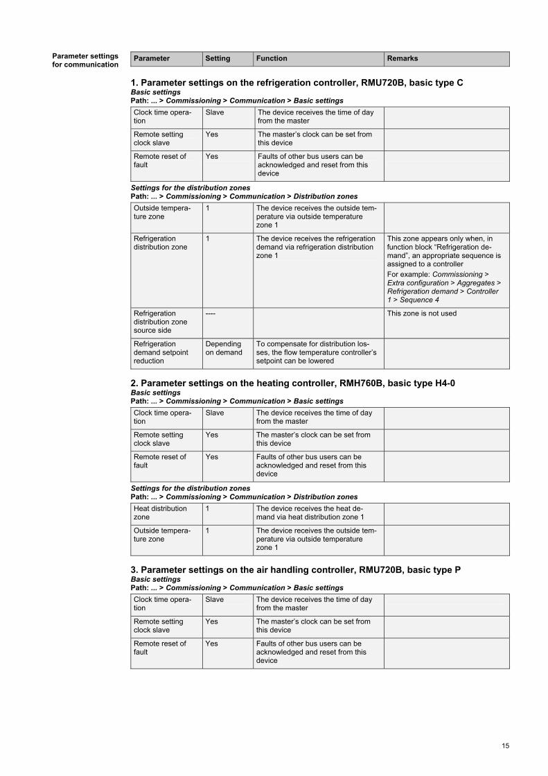
1. Parameter settings on the refrigeration controller, RMU720B, basic type C Basic settings Path: ... > Commissioning > Communication > Basic settings
Clock time opera-tion
Slave The device receives the time of day from the master
Remote setting clock slave
Yes The master’s clock can be set from this device
Remote reset of fault
Yes Faults of other bus users can be acknowledged and reset from this device
Settings for the distribution zones Path: ... > Commissioning > Communication > Distribution zones
Outside tempera-ture zone
1 The device receives the outside tem-perature via outside temperature zone 1
Refrigeration distribution zone
1 The device receives the refrigeration demand via refrigeration distribution zone 1
This zone appears only when, in function block “Refrigeration de-mand”, an appropriate sequence is assigned to a controller
For example: Commissioning > Extra configuration > Aggregates > Refrigeration demand > Controller 1 > Sequence 4
Refrigeration distribution zone source side
---- This zone is not used
Refrigeration demand setpoint reduction
Depending on demand
To compensate for distribution los-ses, the flow temperature controller’s setpoint can be lowered
2. Parameter settings on the heating controller, RMH760B, basic type H4-0 Basic settings Path: ... > Commissioning > Communication > Basic settings
Clock time opera-tion
Slave The device receives the time of day from the master
Remote setting clock slave
Yes The master’s clock can be set from this device
Remote reset of fault
Yes Faults of other bus users can be acknowledged and reset from this device
Settings for the distribution zones Path: ... > Commissioning > Communication > Distribution zones
Heat distribution zone
1 The device receives the heat de-mand via heat distribution zone 1
Outside tempera-ture zone
1 The device receives the outside tem-perature via outside temperature zone 1
3. Parameter settings on the air handling controller, RMU720B, basic type P Basic settings Path: ... > Commissioning > Communication > Basic settings
Clock time opera-tion
Slave The device receives the time of day from the master
Remote setting clock slave
Yes The master’s clock can be set from this device
Remote reset of fault
Yes Faults of other bus users can be acknowledged and reset from this device

16
Parameter Setting Function Remarks
Settings for the distribution zones Path: ... > Commissioning > Communication > Distribution zones
Outside tempera-ture zone
1 The device distributes the outside temperature in outside temperature zone 1
Air distribution zone
1 The device sends the actual value of the supply air temperature to the other bus users in this zone and receives from them their air volume request
The air volume request is a request for cold and warm air
Heat distribution zone
1 The device receives the heat de-mand via heat distribution zone 1
This zone appears only when, in function block “Heat demand”, an appropriate sequence is assigned to a controller
For example: Commissioning > Extra configuration > Aggregates > Heat demand > Controller 1 > Sequence 2
Refrigeration distribution zone
1 The device receives the refrigeration demand via refrigeration distribution zone 1
This zone appears only when, in function block “Refrigeration de-mand”, an appropriate sequence is assigned to a controller
For example: Commissioning > Extra configuration > Aggregates > Refrigeration demand > Controller 1 > Sequence 4
4. Parameter settings on the central control unit RMB795B Basic settings Path: ... > Commissioning > Communication > Basic settings
Clock time opera-tion
Master The device forwards the time of day to the slave bus users
Remote setting clock slave
Yes The master’s clock can be set from this device
This setting does not apply since the device operates as the master
Remote reset of fault
Yes Faults of other bus users can be acknowledged and reset from this device
Settings for room group 1 Path: ... > Commissioning > Communication > Room group 1
Geographical zone (apartm)
4 The device distributes the time pro-gram in geographical zone 4
QAW operation zone (apartm)
---- If a QAW740 room unit is used, its geographical zone can be set here
Holidays / special day operation
Autonomous Information about holidays and spe-cial days is not distributed in the holidays / special day zone
The setting is to be made in room group 1 via menu Holidays/special days. The setting has an effect on the time program. The device dis-tributes the time program to the RDG of the same geographical zone
Settings for the distribution zones Path: ... > Commissioning > Communication > Distribution zones
Outside tempera-ture zone
1 The device receives the outside tem-perature via outside temperature zone 1

17
Parameter Setting Function Remarks
5. Parameter settings on room thermostat 1, RDG400KN Settings for the zones Path: ... > Communication P82 - geographical
zone (apartm) 4 Room group number
P83 - geographical zone (room)
2 Room number Consecutive numbering 1-x when there are several RDG in the same room group
P87 - air distribu-tion zone
1 Air distribution zone
6. Parameter settings on on VAV controller supply air, GDB181.1E/KN Parameter settings Path: ... > Operation settings Master / Slave Master Supply air VAV controller
Minimum volume flow
25%
Maximum volume flow
95%
Settings for the zones Path: ... > Communication Geographical zone
(apartm) 4 Room group number
Geographical zone (room)
1 Room number
Air distribution zone
1 Air distribution zone
7. Parameter settings on VAV controller extract air, GDB181.1E/KN Parameter settings Path: ... > Operation settings Master / Slave Slave Extract air VAV controller
Minimum volume flow
0%
Maximum volume flow
100%
Settings for the zones Path: ... > Communication Geographical zone
(apartm) 4 Room group number
Geographical zone (room)
1 Room number
Air distribution zone
1 Air distribution zone

18
2. 2-pipe fan coil units with heating / cooling changeover and RXB room controllers
Partial air conditioning plant for rooms where the room temperature shall be kept constant by heating or cooling the supply air.
This plant description describes a complete application with 2 rooms, covering the genera-tion of heat or refrigeration, 2-pipe flow temperature control and 2-pipe fan coil units in the 2 rooms. The water temperature in the fan coil units is controlled according to the demand for heat or cooling energy from the rooms. The setpoints and operating modes are controlled from a central location.
Plant diagram Heating or refrigeration plant
Generation of heat or refrigeration
Flow temperature control 2-pipe systems
Room application Room air handling
S
01
S1
F3
F2T
F1T
B2
T
E1 M1
F10B7
Y1
M2
F20
HB0001 H6B HQ (basic type H4-0)
M11
p
B21
M7
RMS705B No standard application available
M4
1 2 S5
S01
T B11
MY5
C0B001 U1B HQ (basic type C)
RMB795B No standard application available
Q1
YRD1 D2
T
D3
T
D4
YHC
T
B1
R1T
XFNC03 B22 HQ
Q1
D1 D2
T
D3
YHC
M
YM
T
D4
T
B1
R1T
XFNC10 B21 HQ

19
Topology
Communication diagram
Generation of refrigeration / heat
Flow tem-perature control
Central control unit
Room air handling
Data points RMS705B RMH760B RMU710B RMB795B RXB22.1/ FC-12
RXB21.1/ FC-11
Room temperature sensor X X Outside temperature sensor X Heating / cooling changeover X Time of day Time switch Holdays / special days Outside temperature Heat request Refrigeration request
= transmitter = receiver
RMS705B No standard application available
RMH760B HB0001 H6B HQ (basic type H4-0)
RMU710B C0B001 U1B HQ (basic type C)
RXB22.1/FC12 XFNC03 B22 HQ
RXB21.1/FC11 XFNC10 B21 HQ
RMB795B No standard application available

20
Communication settings
Generation of refrigeration / heat
Flow tem-perature control
Central control unit
Room air handling
Zones / settings RMS705B RMH760B RMU710B RMB795B RXB22.1/FC-12
RXB21.1/FC-11
Clock time master X Time switch master X
Prerequisites / assumptions
Holidays / special day master
X
Clock time operation Slave Slave Slave Master Remote setting clock slave
Yes Yes Yes Yes Basic settings
Fault remote reset Yes Yes Yes Yes Geographical zone 4.1.1 4.1.1 4.2.1 Room / room
group Time switch slave 4.1.1 4.1.1 Outside temperature zone
1 1 1 1 1
Heat distribution zone
1 2 2 2
Heat distribution zone source side
1
Distribution zones
Refrigeration distribution zone
1 2 2 2
Refrigeration distribution zone source side
1
Function description
Description of functions
Synchronization of clock time
The clock time can be set on any of the Synco 700 controllers (RMH, RMU, RMS, RMB) and is synchro-nized throughout the system.
Time switch
Geographical zone The time switch master – in this case the central control unit (RMB) – forwards the Comfort, Precomfort and Economy modes to all room controllers (RXB) in its geographical zone. This means that all room con-trollers (RXB) operate according to the time switch of the time switch master.
With the room controllers (RXB), the address to be set for the time switch zone is the address of the time switch master’s geographical zone.
Holidays / special days
Geographical zone With the room controllers (RXB), it is not possible to set a holidays / special day zone. This information is dis-tributed in the geographical zone via the time program.
Outside temperature
Outside temperature zone The central control unit (RMB) distributes the outside temperature in outside temperature zone 1. All de-vices in outside temperature zone 1 operate with the same outside temperature.
Optimization of energy usage room
Heat distribution zone When the room calls for heat, the room controller (RXB) forwards a heat request to the flow tempera ture controller (RMU, basic type C) via heat distribu-tion zone 2.
Refrigeration distribution zone
When the room calls for cooling, the room controller (RXB) forwards a refrigeration request to the flow temperature controller (RMU, basic type C) via refrig-eration distribution zone 2.
Heating / cooling changeover The flow temperature controller (RMU, basic type C) transmits the heating / cooling changeover signal in the heat and refrigeration distribution zone. This func-tion must be activated via Extra configuration.
The room controller (RXB) decides whether the water is suited for heating or cooling.
Optimization of energy usage primary side
Heat distribution zone When flow temperature control (RMU, basic type C) calls for heat, it forwards a heat request to heat gen-eration (RMH) via heat distribution zone 1, provided heating / cooling changeover demands heat.
Heat generation (RMH) provides heat only when at least one of the consumers in the system calls for it (demand-dependent control).
Refrigeration distribution zone
When flow temperature control (RMU, basic type C) calls for cooling, it forwards a refrigeration request to refrigeration generation (RMS) via refrigeration distri-bution zone 1, provided heating / cooling changeover demands cooling.
Refrigeration generation provides chilled water only when at least one of the consumers in the system calls for it (demand-dependent control). In addition, the production of chilled water is locked via the time switch.

21
Parameter settings for communication
Parameter Setting Function Remarks
1. Parameter settings on the refrigeration controller, RMS705B Basic settings Path: ... > Commissioning > Communication > Basic settings
Clock time opera-tion
Slave The device receives the time of day from the master
Remote setting clock slave
Yes The master’s clock can be set from this device
Remote reset of fault
Yes Faults of other bus users can be acknowledged and reset from this device
Settings for the distribution zones Path: ... > Commissioning > Communication > Distribution zones
Outside tempera-ture zone
1 The device receives the outside tem-perature via outside temperature zone 1
Refrigeration distribution zone
1 The device receives the refrigeration demand via refrigeration distribution zone 1
To enable the controller to give consideration to refrigeration de-mands, it must be internally con-nected to function block ”Refrigera-tion demand”
For example: Commissioning > Extra configuration > Controller > Controller 1 > Universal shift = Refrig request mod
2. Parameter settings on the heating controller, RMH760B, basic type H4-0 Basic settings Path: ... > Commissioning > Communication > Basic settings
Clock time opera-tion
Slave The device receives the time of day from the master
Remote setting clock slave
Yes The master’s clock can be set from this device
Remote reset of fault
Yes Faults of other bus users can be acknowledged and reset from this device
Settings for the distribution zones Path: ... > Commissioning > Communication > Distribution zones
Heat distribution zone
1 The device receives the heat de-mand via heat distribution zone 1
Outside tempera-ture zone
1 The device receives the outside temperature via outside temperature zone 1
3. Parameter settings on flow temperature controller RMU710B, basic type C Basic settings Path: ... > Commissioning > Communication > Basic settings
Clock time opera-tion
Slave The device receives the time of day from the master
Remote setting clock slave
Yes The master’s clock can be set from this device
Remote reset of fault
Yes Faults of other bus users can be acknowledged and reset from this device

22
Parameter Setting Function Remarks
Settings for the distribution zones
Path: ... > Commissioning > Communication > Distribution zones
Outside tempera-ture zone
1 The device receives the outside temperature via outside temperature zone 1
Heat distribution zone
2 The device receives the heat de-mand via heat distribution zone 2
Heat distribution zone source side
1 The device forwards the heat request to the heating controller via heat distribution zone 1
Heat demand setpoint increase
Depending on demand
To compensate for distribution los-ses, the flow temperature controller’s setpoint can be increased
Refrigeration distribution zone
2 The device receives the refrigeration demand via refrigeration distribution zone 2
Refrigeration distribution zone source side
1 The device forwards the refrigeration request to the refrigeration controller via refrigeration distribution zone 1
Refrigeration demand setpoint reduction
Depending on demand
To compensate for distribution los-ses, the flow temperature controller’s setpoint can be lowered
The heating / cooling changeover signal is transmitted in the heat or refrigeration distribution zone
The heating / cooling changeover signal in Extra configuration must be activated
Path: Commissioning > Extra configuration > Heating/cooling changeover > 2-pipe system H/C = yes
4. Parameter settings on the central control unit RMB795B Basic settings Path: ... > Commissioning > Communication > Basic settings
Clock time opera-tion
Master The device forwards the time of day to the slave bus users
Remote setting clock slave
Yes The master’s clock can be set from this device
This setting does not apply since the device operates as the master
Remote reset of fault
Yes Faults of other bus users can be acknowledged and reset from this device
Settings for room group 1 Path: ... > Commissioning > Communication > Room group 1
Geographical zone (apartm)
4 The device distributes the time pro-gram in geographical zone 4
QAW operation zone (apartm)
---- If a QAW740 room unit is used, its geographical zone can be set here
Holidays / special day operation
Autonomous Information about holidays and spe-cial days is not distributed in the holidays / special day zone
The setting is to be made in room group 1 via menu Holidays / special days. The setting has an effect on the time program. The device dis-tributes the time program to the RXB of the same geographical zone
Settings for the distribution zones Path: ... > Commissioning > Communication > Distribution zones
Outside tempera-ture zone
1 The device forwards the outside temperature via outside temperature zone 1

23
Parameter Setting Function Remarks
5. Parameter settings on room controller 1, RXB22.1/FC-12 Settings for the zones Path: ... > Communication Geographical zone
(apartm) 4 Room group number
Geographical zone (room)
1 Room number
Geographical zone (subzone)
1 Number of the controller in the room
Time switch zone (apartm)
4 Geographical zone of time switch master (apartment)
Time switch zone (room)
1 Geographical zone of time switch master (room)
Time switch zone (subzone)
1 Geographical zone of time switch master (subzone)
Heat distribution zone
2 The device forwards the heat request to the flow temperature controller via heat distribution zone 2
Refrigeration distribution zone
2 The device forwards the refrigeration request to the flow temperature con-troller via refrigeration distribution zone 2
6. Parameter settings on room controller 2, RXB21.1/FC-11 Settings for the zones Path: ... > Communication Geographical zone
(apartm) 4 Room group number
Geographical zone (room)
2 Room number
Geographical zone (subzone)
1 Number of the device in the room
Time switch zone (apartm)
4 Geographical zone of time switch master (apartment)
Time switch zone (room)
1 Geographical zone of time switch master (room)
Time switch zone (subzone)
1 Geographical zone of time switch master (subzone)
Heat distribution zone
2 The device forwards the heat request to the flow temperature controller via heat distribution zone 2
Refrigeration distribution zone
2 The device forwards the refrigeration request to the flow temperature cont-roller via refrigeration distribution zone 2
Outside tempera-ture zone
1 The device receives the outside tem-perature from the RMB via outside temperature zone 1

24
3. 4-pipe fan coil units with RXB room controllers
Partial air conditioning plant for rooms where the room temperature shall be kept constant by heating or cooling the supply air.
This plant description describes a complete application with 2 rooms, covering the genera-tion of heat or refrigeration and 4-pipe fan coil units in 2 rooms. The water temperature in the fan coil units is controlled according to the demand for heat or cooling energy from the rooms. The setpoints and operating modes are controlled from a central location.
Plant diagram Heating or refrigeration plant
Generation of heat or refrigeration
Central control unit Room application Room air handling
S01
S1
F3
F2T
F1T
B2
T
E1 M1
F10B7
Y1
M2
F20
HB0001 H6B HQ (basic type H4-0)
M11
p
B21
M7
RMS705B No standard application available
RMB795B No standard application available
Q1
D1 D2
YC
YH
T
B1
R1T
XFNC04 B21 HQ
Q1
D1 D2
YC
YH
TB1
R1T
XFNC08 B21 HQ

25
Topology
Communication diagram
Generation of refrigeration / heat
Central control unit Room air handling
Data points RMS705B RMH760B RMB795B RXB21.1/ FC-10
RXB21.1/ FC-10
Room temperature sensor X X Outside temperature sensor
X
Supply air temperature sensor
X
Time of day Time switch Holdays / special days Outside temperature Heat request Refrigeration request
= transmitter = receiver Communication settings
Generation of refrigeration / heat
Central control unit
Room air handling
Zones / settings RMS705B RMH760B RMB795B RXB21.1/FC-10
RXB21.1/FC-10
Clock time master X Time switch master X
Prerequisites / assumptions
Holidays / special day master
X
Clock time operation Slave Slave Master Remote setting clock slave Yes Yes Yes
Basic settings
Fault remote reset Yes Yes Yes Geographical zone 3.1.1 3.1.1 3.2.1 Room / room
group Time switch slave 3.1.1 3.1.1 Outside temperature zone 1 1 1 1 Heat distribution zone 1 2 2 Heat distribution zone consumer side
2
Heat distribution zone source side
1
Refrigeration distribution zone
1 2 2
Refrigeration distribution zone consumer side
2
Distribution zones
Refrigeration distribution zone source side
1
RMS705B No standard application available
RMH760B HB0001 H6B HQ (basic type H4-0)
RMB795B No standard application available
RXB21.1/FC10 XFNC04 B21 HQ
RXB21.1/FC10 XFNC08 B21 HQ

26
Function description
Description of functions
Synchronization of clock time
The clock time can be set on any of the Synco 700 controllers (RMH, RMS, RMB) and is synchronized throughout the system.
Time switch
Geographical zone The time switch master – in this case the central control unit (RMB) – forwards the Comfort, Precomfort and Economy modes to all room controllers (RXB) in its geographical zone. This means that all room con-trollers (RXB) operate according to the time switch of the time switch master.
With room controllers (RXB), the address of the time switch master’s geographical zone must be set on the slave zone’s time switch.
Holidays / special days
Geographical zone With the room controllers (RXB), it is not possible to set a holidays / special day zone. This information is distributed in the geographical zone via the time program.
Outside temperature
Outside temperature zone The central control unit (RMB) distributes the outside temperature in outside temperature zone 1. All de-vices in outside temperature zone 1 operate with the same outside temperature.
Optimization of energy usage room
Heat distribution zone When the room calls for heat, the room controller (RXB) forwards a heat request to the central control unit (RMB) via heat distribution zone 2.
Refrigeration distribution zone
When the room calls for cooling, the room controller (RXB) forwards a refrigeration request to the central control unit (RMB) via refrigeration distribution zone 2. Optimization of energy usage primary side
Heat distribution zone The central control unit collects the heat requests, evaluates them and forwards a heat request to heat generation (RMH) via heat distribution zone 1.
Heat generation (RMH) provides heat only when at least one of the consumers in the system calls for it (demand-dependent control).
Refrigeration distribution zone
The central control unit collects the refrigeration re-quests, evaluates them and forwards a refrigeration request to refrigeration generation (RMS) via refrigera-tion distribution zone 1.
Refrigeration generation provides chilled water only when at least one of the consumers in the system calls for it (demand-dependent control). In addition, the production of chilled water is locked via the time switch.
Parameter settings for communication
Parameter Setting Function Remarks
1. Parameter settings on the refrigeration controller, RMS705B Basic settings Path: ... > Commissioning > Communication > Basic settings
Clock time opera-tion
Slave The device receives the time of day from the master
Remote setting clock slave
Yes The master’s clock can be set from this device
Remote reset of fault
Yes Faults of other bus users can be acknowledged and reset from this device
Settings for the distribution zones Path: ... > Commissioning > Communication > Distribution zones
Outside tempera-ture zone
1 The device receives the outside tem-perature via outside temperature zone 1
Refrigeration distribution zone
1 The device receives the refrigeration demand via refrigeration distribution zone 1
To enable the controller to give consideration to refrigeration de-mands, it must be internally con-nected to function block ”Refrigera-tion demand”
For example: Commissioning > Extra configuration > Controller > Controller 1 > Universal shift = Refrig request mod

27
Parameter Setting Function Remarks
2. Parameter settings on the heating controller, RMH760B, basic type H4-0 Basic settings Path: ... > Commissioning > Communication > Basic settings
Clock time opera-tion
Slave The device receives the time of day from the master
Remote setting clock slave
Yes The master’s clock can be set from this device
Remote reset of fault
Yes Faults of other bus users can be acknowledged and reset from this device
Settings for the distribution zones Path: ... > Commissioning > Communication > Distribution zones
Heat distribution zone
1 The device receives the heat de-mand via heat distribution zone 1
Outside tempera-ture zone
1 The device receives the outside tem-perature via outside temperature zone 1
3. Parameter settings on the central control unit RMB795B Basic settings Path: ... > Commissioning > Communication > Basic settings
Clock time opera-tion
Master The device forwards the time of day to the slave bus users
Remote setting clock slave
Yes The master’s clock can be set from this device
This setting does not apply since the device operates as master
Remote reset of fault
Yes Faults of other bus users can be acknowledged and reset from this device
Settings for room group 1 Path: ... > Commissioning > Communication > Room group 1
Geographical zone (apartm)
3 The device distributes the time pro-gram in geographical zone 3
QAW operation zone (apartm)
---- If a QAW740 room unit is used, its geographical zone can be set here
Holidays / special day operation
Autonomous Information about holidays and spe-cial days is not distributed in the holidays / special day zone
The setting is to be made in room group 1 via menu Holidays / special days. The setting has an effect on the time program. The device dis-tributes the time program to the RXB of the same geographical zone
Settings for the distribution zones Path: ... > Commissioning > Communication > Distribution zones
Outside tempera-ture zone
1 The device forwards the outside temperature via outside temperature zone 1
Heat distribution zone source side
1 The device forwards the heat request to the heating controller via heat distribution zone 1
Heat distribution zone consumer side
2 The device receives the heat de-mand via heat distribution zone 2
Refrigeration distribution zone source side
1 The device forwards the refrigeration request to the refrigeration controller via refrigeration distribution zone 1
Refrigeration distribution zone consumer side
2 The device receives the refrigeration demand via refrigeration distribution zone 2

28
Parameter Setting Function Remarks
4. Parameter settings on room controller 1, RXB21.1/FC-10 Settings for the zones Path: ... > Communication Geographical zone
(apartm) 3 Room group number
Geographical zone (room)
1 Room number
Geographical zone (subzone)
1 Number of controller in the room
Time switch zone (apartm)
3 Geographical zone of time switch master (apartment)
Time switch zone (room)
1 Geographical zone of time switch master (room)
Time switch zone (subzone)
1 Geographical zone of time switch master (subzone)
Heat distribution zone
2 The device forwards the heat request to the RMB via heat distribution zone 2
Refrigeration distribution zone
2 The device forwards the refrigeration request to the RMB via refrigeration distribution zone 2
5. Parameter settings on room controller 2, RXB21.1/FC-10 Settings for the zones Path: ... > Communication Geographical zone
(apartm) 3 Room group number
Geographical zone (room)
2 Room number
Geographical zone (subzone)
1 Number of the controller in the room
Time switch zone (apartm)
3 Geographical zone of time switch master (apartment)
Time switch zone (room)
1 Geographical zone of time switch master (room)
Time switch zone (subzone)
1 Geographical zone of time switch master (subzone)
Heat distribution zone
2 The device forwards the heat request to the RMB via heat distribution zone 2
Refrigeration distribution zone
2 The device forwards the refrigeration request to the RMB via refrigeration distribution zone 2
Outside tempera-ture zone
1 The device receives the outside tem-perature via outside temperature zone 1

29
4. 2-pipe fan coil units with heating / cooling changeover and RDG room thermostats
Partial air conditioning plant for rooms where the room temperature shall be kept constant by heating or cooling the supply air.
This plant description describes a complete application with 2 rooms, covering the genera-tion of heat or refrigeration, 2-pipe flow temperature control and 2-pipe fan coil units in the 2 rooms. The water temperature in the fan coil units is controlled according to the demand for heat or cooling energy from the rooms. The setpoints and operating modes are controlled from a central location.
Plant diagram Heating or refrigeration plant
Generation of heat or refrigeration
Flow temperature control Room application Room air handling
S0
1
S1
F3
F2T
F1T
B2
T
E1 M1
F10B7
Y1
M2
F20
HB0001 H6B HQ (basic type H4-0)
M11
p
B21
M7
RMS705B No standard application available
M4
1 2 S5
S01
T B11
MY5
C0B001 U1B HQ (basic type C)
RMB795B No standard application available
TAAA01 DG1 HQ
Y1
M1
3076S
02
T
YE
T
(B1)
T
(B1)
B2
TAAB01 DG1 HQ

30
Topology
Communication diagram
Generation of refrigeration / heat
Flow tem-perature control
Central control unit
Room air handling
Data points RMS705B RMH760B RMU710B RMB795B RDG100KN RDG100KN Room temperature sensor X X Outside temperature sensor X Heating / cooling changeover X Time of day Time switch Holdays / special days Outside temperature Heat request Refrigeration request
= transmitter = receiver Communication settings
Generation of refrigeration / heat
Flow tem-perature control
Central control
unit
Room air handling
Zones / settings RMS705B RMH760B RMU710B RMB795B RDG100KN RDG100KNClock time master X Time switch master X
Prerequisites / assumptions
Holidays / special day master
X
Clock time operation Slave Slave Slave Master Remote setting clock slave
Yes Yes Yes Yes Basic settings
Fault remote reset Yes Yes Yes Yes Room / room group
Geographical zone 4.1.1 4.1.1 4.2.1
Outside temperature zone
1 1 1 1
Heat distribution zone
1 2 2 2
Heat distribution zone source side
1
Refrigeration distribution zone
1 2 2 2
Distribution zones
Refrigeration distribution zone source side
1
RMS705B No standard application available
RMH760B HB0001 H6B HQ (basic type H4-0)
RMU710B C0B001 U1B HQ (basic type C)
RDG100KN TAAA01 DG1 HQ
RDG100KN TAAB01 DG1 HQ
RMB795B No standard application available

31
Function description
Description of functions
Synchronization of clock time
The clock time can be set on any of the Synco 700 controllers (RMH, RMU, RMS, RMB) and is synchro-nized throughout the system.
The clock time can also be displayed on the room thermostats (RDG).
Time switch
Geographical zone The time switch master – in this case the central control unit (RMB) – forwards the Comfort, Precomfort and Economy modes to all room thermostats (RDG) in its geographical zone. This means that all room thermostats (RDG) operate according to the time switch of the time switch master.
With the room thermostats (RDG), there is no time switch slave zone available. Here, the apartment address of the geographical zone must be identical with that of the time switch master. With the room thermostats (RDG), the subzone address is always 1 and cannot be changed.
Holidays / special days
Geographical zone With the room thermostats (RDG), it is not possible to set a holidays / special day zone. This information is distributed in the geographical zone via the time program.
Outside temperature
Outside temperature zone The central control unit (RMB) distributes the outside temperature in outside temperature zone 1. All de-vices in outside temperature zone 1 operate with the same outside temperature.
Optimization of energy usage room
Heat distribution zone When the room calls for heat, the room controller (RXB) forwards the heat request to the flow tempera-
ture controller (RMU, basic type C) via heat distribu-tion zone 2. Refrigeration distribution zone
When the room calls for cooling, the room controller (RXB) forwards a refrigeration request to the flow temperature controller (RMU, basic type C) via refrig-eration distribution zone 2.
Heating / cooling changeover The flow temperature controller (RMU, basic type C) transmits the heating / cooling changeover signal in the heat and refrigeration distribution zone. This func-tion must be activated via Extra configuration.
The room controller (RXB) decides whether the water is suited for heating or cooling.
Optimization of energy usage primary side
Heat distribution zone When flow temperature control (RMU, basic type C) calls for heat, it forwards a heat request to heat gen-eration (RMH) via heat distribution zone 1, provided heating / cooling changeover demands heat.
Heat generation (RMH) provides heat only when at least one of the consumers in the system calls for it (demand-dependent control).
Refrigeration distribution zone
When flow temperature control (RMU, basic type C) calls for cooling, it forwards a refrigeration request to refrigeration generation (RMS) via refrigeration distri-bution zone 1, provided heating / cooling changeover demands cooling.
Refrigeration generation provides chilled water only when at least one of the consumers in the system calls for it (demand-dependent control). In addition, the production of chilled water is locked via the time switch.
Parameter settings for communication
Parameter Setting Function Remarks
1. Parameter settings on the refrigeration controller, RMS705B Basic settings Path: ... > Commissioning > Communication > Basic settings
Clock time opera-tion
Slave The device receives the time of day from the master
Remote setting clock slave
Yes The master’s clock can be set from this device
Remote reset of fault
Yes Faults of other bus users can be acknowledged and reset from this device

32
Parameter Setting Function Remarks
Settings for the distribution zones
Path: ... > Commissioning > Communication > Distribution zones
Outside tempera-ture zone
1 The device receives the outside tem-perature via outside temperature zone 1
Refrigeration distribution zone
1 The device receives the refrigeration demand via refrigeration distribution zone 1
To enable the controller to give consideration to refrigeration de-mands, it must be internally con-nected to function block ”Refrigera-tion demand”
For example: Commissioning > Extra configuration > Controller > Controller 1 > Universal shift = Refrig request mod
2. Parameter settings on the heating controller, RMH760B, basic type H4-0 Basic settings Path: ... > Commissioning > Communication > Basic settings
Clock time opera-tion
Slave The device receives the time of day from the master
Remote setting clock slave
Yes The master’s clock can be set from this device
Remote reset of fault
Yes Faults of other bus users can be acknowledged and reset from this device
Settings for the distribution zones Path: ... > Commissioning > Communication > Distribution zones
Heat distribution zone
1 The device receives the heat de-mand via heat distribution zone 1
Outside tempera-ture zone
1 The device receives the outside tem-perature via outside temperature zone 1
3. Parameter settings on flow temperature controller RMU710B, basic type C Basic settings Path: ... > Commissioning > Communication > Basic settings
Clock time opera-tion
Slave The device receives the time of day from the master
Remote setting clock slave
Yes The master’s clock can be set from this device
Remote reset of fault
Yes Faults of other bus users can be acknowledged and reset from this device
Settings for the distribution zones Path: ... > Commissioning > Communication > Distribution zones
Outside tempera-ture zone
1 The device receives the outside temperature via outside temperature zone 1
Heat distribution zone
2 The device receives the heat de-mand via heat distribution zone 2
Heat distribution zone source side
1 The device forwards the heat request to the heating controller via heat distribution zone 1
Heat demand setpoint increase
Depending on demand
To compensate for distribution los-ses, the flow temperature controller’s setpoint can be increased
Refrigeration distribution zone
2 The device receives the refrigeration demand via refrigeration distribution zone 2
Refrigeration distribution zone source side
1 The device forwards the refrigeration request to the refrigeration controller via refrigeration distribution zone 1
Refrigeration demand setpoint reduction
Depending on demand
To compensate for distribution los-ses, the flow temperature controller’s setpoint can be lowered
The heating / cooling changeover signal is transmitted in the heat or refrigeration distribution zone.
The heating / cooling changeover signal in Extra configuration must be activated
Path: Commissioning > Extra configuration > Heating/cooling changeover > 2-pipe system H/C = yes

33
Parameter Setting Function Remarks
4. Parameter settings on the central control unit RMB795B Basic settings Path: ... > Commissioning > Communication > Basic settings
Clock time opera-tion
Master The device forwards the time of day to the slave bus users
Remote setting clock slave
Yes The master’s clock can be set from this device
This setting does not apply since the device operates as master
Remote reset of fault
Yes Faults of other bus users can be acknowledged and reset from this device
Settings for room group 1 Path: ... > Commissioning > Communication > Room group 1
Geographical zone (apartm)
4 The device distributes the time pro-gram in geographical zone 4
QAW operation zone (apartm)
---- If a QAW740 room unit is used, its geographical zone can be set here
Holidays / special day operation
Autonomous Information about holidays and spe-cial days is not distributed in the holidays / special day zone
The setting is to be made in room group 1 via menu Holidays / special days. The setting has an effect on the time program. The device dis-tributes the time program to the RDG of the same geographical zone
Settings for the distribution zones Path: ... > Commissioning > Communication > Distribution zones
Outside tempera-ture zone
1 The device forwards the outside temperature via outside temperature zone 1
5. Parameter settings on room thermostat 1, RDG100KN Settings for the zones Path: ... > Communication P82 - geographical
zone (apartm) 4 Room group number
P83 - geographical zone (room)
1 Room number Consecutive numbering 1-x when there are several RDG in the same room group
P84 - heat distribu-tion zone
2 The device forwards the heat re-quest to the flow temperature cont-roller via heat distribution zone 2
P85 - refrigeration distribution zone
2 The device forwards the refrigeration request to the flow temperature cont-roller via refrigeration distribution zone 2
6. Parameter settings on room thermostat 2, RDG100KN Settings for the zones Path: ... > Communication P82 - geographical
zone (apartm) 4 Room group number
P83 - geographical zone (room)
2 Room number Consecutive numbering 1-x when there are several RDG in the same room group
P84 - heat distribu-tion zone
2 The device forwards the heat request to the flow temperature controller via heat distribution zone 2
P85 - refrigeration distribution zone
2 The device forwards the refrigeration request to the flow temperature cont-roller via refrigeration distribution zone 2

34
5. 4-pipe fan coil units with RDG room thermostats
Partial air conditioning plant for rooms where the room temperature shall be kept constant by heating or cooling the supply air.
This plant description describes a complete application with 2 rooms, covering the genera-tion of heat or refrigeration and 4-pipe fan coil units in the 2 rooms. The water temperature in the fan coil units is controlled according to the demand for heat or cooling energy from the rooms. The setpoints and operating modes are controlled from a central location.
Plant diagram Heating or refrigeration plant
Generation of heat or refrigeration
Central control unit Room application Room air handling
S
01
S1
F3
F2T
F1T
B2
T
E1 M1
F10B7
Y1
M2
F20
HB0001 H6B HQ (basic type H4-0)
M11
p
B21
M7
RMS705B No standard application available
RMB795B No standard application available
TABA01 DG1 HQ
T
Y2
Y1
M1
3076S
05
(B1)
T
(B1)
YE
B2
TABB01 DG1 HQ

35
Topology
Communication diagram
Generation of refrigeration / heat
Central control unit Room air handling
Data points RMS705B RMH760B RMB795B RDG100KN RDG100KN Room temperature sensor X X Outside temperature sensor
X
Supply air temperature sensor
X
Time of day Time switch Holdays / special days Outside temperature Heat request Refrigeration request
= transmitter = receiver Communication settings
Generation of refrigeration / heat
Central control unit
Room air handling
Zones / settings RMS705B RMH760B RMB795B RDG100KN RDG100KNClock time master X Times witch master X
Prerequisites / assumptions
Holidays / special day master
X
Clock time operation Slave Slave Master Remote setting clock slave Yes Yes Yes
Basic settings
Fault remote reset Yes Yes Yes Room / room group
Geographical zone 3.1.1 3.1.1 3.2.1
Outside temperature zone 1 1 1 Heat distribution zone 1 1 1
Distribution zones
Refrigeration distribution zone
1 1 1
RMS705B No standard application available
RMH760B HB0001 H6B HQ (basic type H4-0)
RMB795B No standard application available RDG100KN
TABA01 DG1 HQ
RDG100KN TABB01 DG1 HQ

36
Function description
Description of functions
Synchronization of clock time
The clock time can be set on any of the Synco 700 controllers (RMH, RMS, RMB) and is synchronized throughout the system.
The clock time can also be displayed on the room thermostats (RDG).
Time switch
Geographical zone The time switch master – in this case the central control unit (RMB) – forwards the Comfort, Precomfort and Economy modes to all room thermostats (RDG) in its geographical zone. This means that all room thermostats (RDG) operate according to the time switch of the time switch master.
With the room thermostats (RDG), there is no time switch slave zone available. Here, the apartment address of the geographical zone must be identical with that of the time switch master. With the room thermostats (RDG), the subzone address is always 1 and cannot be changed.
Holidays / special days
Geographical zone With the room thermostats (RDG), it is not possible to set a holidays / special day zone. This information is distributed in the geographical zone via the time program.
Outside temperature
Outside temperature zone The central control unit (RMB) distributes the outside temperature in outside temperature zone 1. All de-vices in outside temperature zone 1 operate with the same outside temperature.
Optimization of energy usage room
Heat distribution zone When the room calls for heat, the room thermostat (RDG) forwards the heat request to heat generation (RMH) via heat distribution zone 1.
Heat generation (RMH) provides heat only when at least one of the consumers in the system calls for it (demand-dependent control).
Refrigeration distribution zone
When the room calls for cooling, the room thermostat (RDG) forwards the refrigeration request to refrigera-tion generation (RMS) via refrigeration distribution zone 1.
Refrigeration generation provides chilled water only when at least one of the consumers in the system calls for it (demand-dependent control). In addition, the production of chilled water is locked via the time switch.
Parameter settings for communication
Parameter Setting Function Remarks
1. Parameter settings on the refrigeration controller, RMS705B Basic settings Path: ... > Commissioning > Communication > Basic settings
Clock time opera-tion
Slave The device receives the time of day from the master
Remote setting clock slave
Yes The master’s clock can be set from this device
Remote reset of fault
Yes Faults of other bus users can be acknowledged and reset from this device
Settings for the distribution zones Path: ... > Commissioning > Communication > Distribution zones
Outside tempera-ture zone
1 The device receives the outside tem-perature via outside temperature zone 1
Refrigeration distribution zone
1 The device receives the refrigeration demand via refrigeration distribution zone 1
To enable the controller to give consideration to refrigeration de-mands, it must be internally con-nected to function block ”Refrigera-tion demand”
For example: Commissioning > Extra configuration > Controller > Controller 1 > Universal shift = Refrig request mod

37
Parameter Setting Function Remarks
2. Parameter settings on the heating controller, RMH760B, basic type H4-0 Basic settings Path: ... > Commissioning > Communication > Basic settings
Clock time opera-tion
Slave The device receives the time of day from the master
Remote setting clock slave
Yes The master’s clock can be set from this device
Remote reset of fault
Yes Faults of other bus users can be acknowledged and reset from this device
Settings for the distribution zones Path: ... > Commissioning > Communication > Distribution zones
Heat distribution zone
1 The device receives the heat de-mand via heat distribution zone 1
Outside tempera-ture zone
1 The device receives the outside tem-perature via outside temperature zone 1
3. Parameter settings on the central control unit RMB795B Basic settings Path: ... > Commissioning > Communication > Basic settings
Clock time opera-tion
Master The device forwards the time of day to the slave bus users
Remote setting clock slave
Yes The master’s clock can be set from this device
This setting does not apply since the device operates as master
Remote reset of fault
Yes Faults of other bus users can be acknowledged and reset from this device
Settings for room group 1 Path: ... > Commissioning > Communication > Room group 1
Geographical zone (apartm)
3 The device distributes the time pro-gram in geographical zone 3
QAW operation zone (apartm)
---- If a QAW740 room unit is used, its geographical zone can be set here
Holidays / special day operation
Autonomous Information about holidays and spe-cial days is not distributed in the holidays / special day zone
The setting is to be made in room group 1 via menu Holidays / special days. The setting has an effect on the time program. The device dis-tributes the time program to the RDG of the same geographical zone
Settings for the distribution zones Path: ... > Commissioning > Communication > Distribution zones
Outside tempera-ture zone
1 The device forwards the outside temperature via outside temperature zone 1
4. Parameter settings on room thermostat 1, RDG100KN Settings for the zones Path: ... > Communication P82 - geographical
zone (apartm) 3 Room group number
P83 - geographical zone (room)
1 Room number Consecutive numbering 1-x when there are several RDG in the same room group
P84 - heat distribu-tion zone
1 The device forwards the heat request via heat distribution zone 2 to the RMH
P85 - refrigeration distribution zone
1 The device forwards the refrigeration request to the RMS via refrigeration distribution zone 2

38
Parameter Setting Function Remarks
5. Parameter settings on room thermostat 2, RDG100KN Settings for the zones Path: ... > Communication P82 - geographical
zone (apartm) 3 Room group number
P83 - geographical zone (room)
2 Room number Consecutive numbering 1-x when there are several RDG in the same room group
P84 - heat distribu-tion zone
1 The device forwards the heat request to the RMH via heat distribution zone 1
P85 - refrigeration distribution zone
1 The device forwards the refrigeration request to the RMS via refrigeration distribution zone 1

39
6. Chilled / heated ceiling and radiator with heating / cooling changeover and RDG room thermostats
Partial air conditioning plant for rooms where the room temperature shall be kept constant by a chilled / heated ceiling and a radiator.
This plant description describes a complete application with 2 rooms, covering the genera-tion of heat or refrigeration, 2-pipe flow temperature control, chilled / heated ceilings and radiators in the 2 rooms. The water temperature in the chilled / heated ceilings is controlled according to the demand for heat or cooling energy from the rooms. The setpoints and ope-rating modes are controlled from a central location.
Plant diagram Heating or refrigeration plant
Generation of heat or refrigeration
Flow temperature control Room application Room temperature control
S
01
S1
F3
F2T
F1T
B2
T
E1 M1
F10B7
Y1
M2
F20
HB0001 H6B HQ (basic type H4-0)
K1 M7 M4
S0
1
M9M11 F7
M
Y14
T
B20
V
F18
Y7
V
F17
T
B11
CBA001 U2B HQ (basic type C)
M4
1 2 S5
S0
1
T B11
MY5
C0B001 U1B HQ (basic type C)
RMB795B No standard application available
TE0001 DG1 HQ
TE0001 DG1 HQ

40
Topology
Communication diagram
Generation of refrigeration / heat
Flow tem-perature control
Central control
unit
Room temperature control
Data points RMU720B RMH760B RMU710B RMB795B RDG100KN RDG100KN Room temperature sensor X X Outside temperature sensor X Heating / cooling changeover X Time of day Time switch Holdays / special days Outside temperature Heat request Refrigeration request
= transmitter = receiver Communication settings
Generation of refrigeration / heat
Flow tem-perature control
Central control
unit
Room temperature control
Zones / settings RMU720B RMH760B RMU710B RMB795B RDG100KN RDG100KNClock time master X Time switch master X
Prerequisites / assumptions
Holidays / special day master
X
Clock time operation Slave Slave Slave Master Remote setting clock slave
Yes Yes Yes Yes Basic settings
Fault remote reset Yes Yes Yes Yes Room / room group
Geographical zone 4.1.1 4.1.1 4.2.1
Outside temperature zone
1 1 1 1
Heat distribution zone
1 2 2 2
Heat distribution zone source side
1
Refrigeration distribution zone
1 2 2 2
Distribution zones
Refrigeration distribution zone source side
1
RMB795B No standard application available
RMU720B CBA001 U2B HQ (basic type C)
RMH760B HB0001 H6B HQ (basic type H4-0)
RMU710B C0B001 U1B HQ (basic type C)
RDG100KN TE0001 DG1 HQ
RDG100KN TE0002 DG1 HQ

41
Function description
Description of functions
Synchronization of clock time
The clock time can be set on any of the Synco 700 controllers (RMH, RMU, RMB) and is synchronized throughout the system.
The clock time can also be displayed on the room thermostats (RDG).
Time switch
Geographical zone The time switch master – in this case the central control unit (RMB) – forwards the Comfort, Precomfort and Economy modes to all room thermostats (RDG) in its geographical zone. This means that all room thermostats (RDG) operate according to the time switch of the time switch master.
With the room thermostats (RDG), there is no time switch slave zone available. Here, the apartment address of the geographical zone must be identical with that of the time switch master. With the room thermostats (RDG), the subzone address is always 1 and cannot be changed.
Holidays / special days
Geographical zone With the room thermostats (RDG), it is not possible to set a holidays / special day zone. This information is distributed in the geographical zone via the time program.
Outside temperature
Outside temperature zone The central control unit (RMB) distributes the outside temperature in outside temperature zone 1. All de-vices in outside temperature zone 1 operate with the same outside temperature.
Optimization of energy usage room
Heat distribution zone When the room calls for heat, the room thermostat (RDG) forwards the heat demand to the flow tempera-
ture controller (RMU, basic type C) via heat distribu-tion zone 2. Refrigeration distribution zone
When the room calls for cooling, the room thermostat (RDG) forwards the refrigeration request to the flow temperature controller (RMU, basic type C) via refrig-eration distribution zone 2.
Heating / cooling changeover The flow temperature controller (RMU, basic type C) transmits the heating / cooling changeover signal in the heat and refrigeration distribution zone. This func-tion must be activated via Extra configuration.
The room thermostat (RDG) decides whether the water is suited for heating or cooling. Optimization of energy usage primary side
Heat distribution zone When flow temperature control (RMU, basic type C) calls for heat, it forwards a heat request to heat gen-eration (RMH) via heat distribution zone 1, provided heating / cooling changeover demands heat.
Heat generation (RMH) provides heat only when at least one of the consumers in the system calls for it (demand-dependent control).
Refrigeration distribution zone
When flow temperature control calls for cooling, it forwards a refrigeration request to refrigeration gen-eration (RMU, basic type C) via refrigeration distribu-tion zone 1, provided heating / cooling changeover demands cooling.
Refrigeration generation provides chilled water only when at least one of the consumers in the system calls for it (demand-dependent control). In addition, the production of chilled water is locked via the time switch.
Parameter settings for communication
Parameter Setting Function Remarks
1. Parameter settings on the refrigeration controller, RMU720B, basic type C Basic settings Path: ... > Commissioning > Communication > Basic settings
Clock time opera-tion
Slave The device receives the time of day from the master
Remote setting clock slave
Yes The master’s clock can be set from this device
Remote reset of fault
Yes Faults of other bus users can be acknowledged and reset from this device

42
Parameter Setting Function Remarks
Settings for the distribution zones
Path: ... > Commissioning > Communication > Distribution zones
Outside tempera-ture zone
1 The device receives the outside tem-perature via outside temperature zone 1
Refrigeration distribution zone
1 The device receives the refrigeration demand via refrigeration distribution zone 1
This zone appears only when, in function block “Refrigeration de-mand”, an appropriate sequence is assigned to a controller
For example: Commissioning > Extra configuration > Aggregates > Refrigeration demand > Controller 1 > Sequence 4
Refrigeration distribution zone source side
---- This zone is not used
Refrigeration demand setpoint reduction
Depending on demand
To compensate for distribution los-ses, the refrigeration source’s set-point can be lowered
2. Parameter settings on the heating controller, RMH760B, basic type H4-0 Basic settings Path: ... > Commissioning > Communication > Basic settings
Clock time opera-tion
Slave The device receives the time of day from the master
Remote setting clock slave
Yes The master’s clock can be set from this device
Remote reset of fault
Yes Faults of other bus users can be acknowledged and reset from this device
Settings for the distribution zones Path: ... > Commissioning > Communication > Distribution zones
Heat distribution zone
1 The device receives the heat de-mand via heat distribution zone 1
Outside tempera-ture zone
1 The device receives the outside tem-perature via outside temperature zone 1
3. Parameter settings on flow temperature controller RMU710B, basic type C Basic settings Path: ... > Commissioning > Communication > Basic settings
Clock time opera-tion
Slave The device receives the time of day from the master
Remote setting clock slave
Yes The master’s clock can be set from this device
Remote reset of fault
Yes Faults of other bus users can be acknowledged and reset from this device
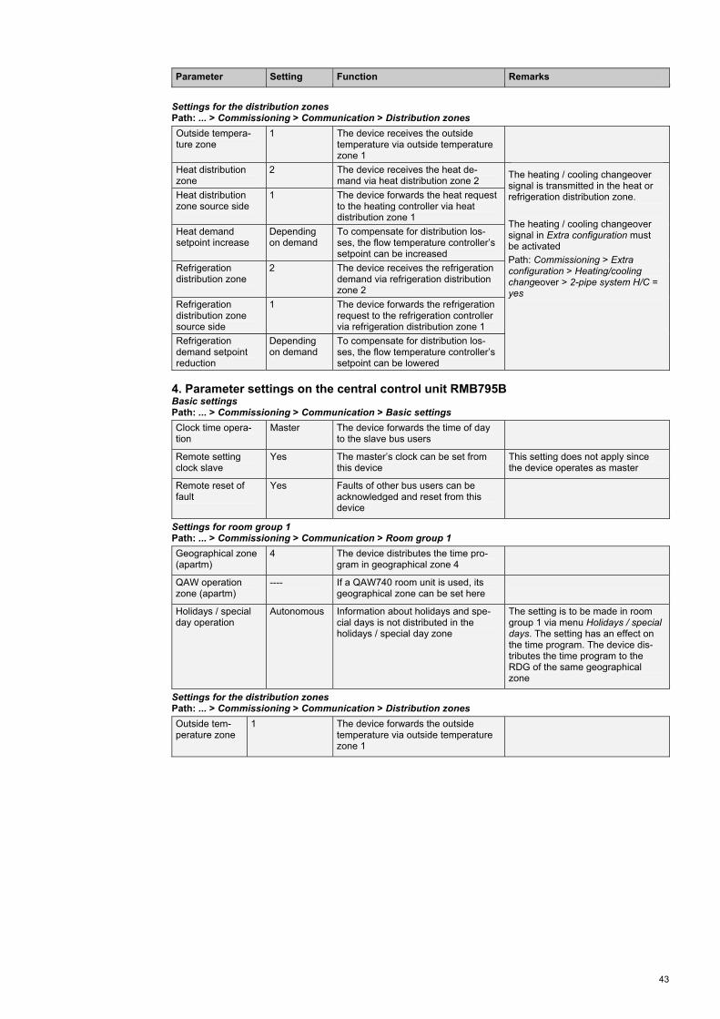
43
Parameter Setting Function Remarks
Settings for the distribution zones
Path: ... > Commissioning > Communication > Distribution zones
Outside tempera-ture zone
1 The device receives the outside temperature via outside temperature zone 1
Heat distribution zone
2 The device receives the heat de-mand via heat distribution zone 2
Heat distribution zone source side
1 The device forwards the heat request to the heating controller via heat distribution zone 1
Heat demand setpoint increase
Depending on demand
To compensate for distribution los-ses, the flow temperature controller’s setpoint can be increased
Refrigeration distribution zone
2 The device receives the refrigeration demand via refrigeration distribution zone 2
Refrigeration distribution zone source side
1 The device forwards the refrigeration request to the refrigeration controller via refrigeration distribution zone 1
Refrigeration demand setpoint reduction
Depending on demand
To compensate for distribution los-ses, the flow temperature controller’s setpoint can be lowered
The heating / cooling changeover signal is transmitted in the heat or refrigeration distribution zone.
The heating / cooling changeover signal in Extra configuration must be activated
Path: Commissioning > Extra configuration > Heating/cooling changeover > 2-pipe system H/C = yes
4. Parameter settings on the central control unit RMB795B Basic settings Path: ... > Commissioning > Communication > Basic settings
Clock time opera-tion
Master The device forwards the time of day to the slave bus users
Remote setting clock slave
Yes The master’s clock can be set from this device
This setting does not apply since the device operates as master
Remote reset of fault
Yes Faults of other bus users can be acknowledged and reset from this device
Settings for room group 1 Path: ... > Commissioning > Communication > Room group 1
Geographical zone (apartm)
4 The device distributes the time pro-gram in geographical zone 4
QAW operation zone (apartm)
---- If a QAW740 room unit is used, its geographical zone can be set here
Holidays / special day operation
Autonomous Information about holidays and spe-cial days is not distributed in the holidays / special day zone
The setting is to be made in room group 1 via menu Holidays / special days. The setting has an effect on the time program. The device dis-tributes the time program to the RDG of the same geographical zone
Settings for the distribution zones Path: ... > Commissioning > Communication > Distribution zones
Outside tem-perature zone
1 The device forwards the outside temperature via outside temperature zone 1

44
Parameter Setting Function Remarks
5. Parameter settings on room thermostat 1, RDG100KN Settings for the zones Path: ... > Communication P82 - geographical
zone (apartm) 4 Room group number
P83 - geographical zone (room)
1 Room number Consecutive numbering 1-x when there are several RDG in the same room group
P84 - heat distribu-tion zone
2 The device forwards the heat request to the flow temperature controller via heat distribution zone 2
P85 - refrigeration distribution zone
2 The device forwards the refrigeration request to the flow temperature cont-roller via refrigeration distribution zone 2
6. Parameter settings on room thermostat 2, RDG100KN Settings for the zones Path: ... > Communication P82 - geographical
zone (apartm) 4 Room group number
P83 - geographical zone (room)
2 Room number Consecutive numbering 1-x when there are several RDG in the same room group
P84 - heat distribu-tion zone
2 The device forwards the heat request to the flow temperature controller via heat distribution zone 2
P85 - refrigeration distribution zone
2 The device forwards the refrigeration request to the flow temperature cont-roller via refrigeration distribution zone 2

45
7. Supply air temperature control with RMU universal controllers
Ventilation plant for rooms where the room temperature shall be kept constant by heating the supply air.
This plant description describes a complete application with 2 partial ventilation plants, cov-ering the generation of heat and its distribution to the air heating coils. The supply air tem-perature is controlled depending on the demand for heat.
Plant diagram Heating plant
Generation of heat Heat distribution Precontrol
Ventilation plants Supply air temperature control
S0
1
S1
F3
F2T
F1T
B2
T
E1 M1
F10B7
Y1
M2
F20
HB0001 H6B HQ (basic type H4-0)
S0
1
B9
M2
F2B7
Y1
M1
B1
S1
F1
H0F001 H6B HQ (basic type H2-0)
1
1
S0
1
M3
M Y1
M Y2
�p
F4
M
Y3
�p
F1
�p
F2
T
B1
TB5
ADA002 U1B HQ (basic type A)
1
1
S0
1
M3
M Y1
M Y2
�p
F4
M
Y3
�p
F1
�p
F2
T
B1
TB5
ADA002 U1B HQ (basic type A)
Topology
RMH760B HB0001 H6B HQ (basic type H4-0)
RMH760B H0F001 H6B HQ (basic type H2-0) RMU710B
ADA002 U1B HQ (basic type A)
RMU710B ADA002 U1B HQ (basic type A)

46
Communication diagram
Generation of heat Distribution of heat Ventilation plants
Data points RMH760B RMH760B RMU710B RMU710B Room temperature sensor X Outside temperature sensor
X X
Time of day Time switch Holidays / special days Outside temperature Heat request
= transmitter = receiver Communication settings
Generation of heat
Distribution of heat
Ventilation plants
Zones / settings RMH760B RMH760B RMU710B RMU710B Clock time master X Time switch master X
Prerequisites / assumptions
Holidays / special day master
X
Clock time operation Slave Slave Master Slave Remote setting clock slave Yes Yes Yes Yes
Basic settings
Fault remote reset Yes Yes Yes Yes Geographical zone 3.1.1 Room / room
group Time switch slave 3.1.1 Holidays / special day operation
Master Slave Holidays / special days
Holidays / special day zone 1 1 Outside temperature zone 1 1 1 1 Heat distribution zone 1 2 2 Heat distribution zone source side
1
Distribution zones
Heat distribution zone consumer side
2
Function description
Description of functions
Synchronization of clock time
The clock time can be set on any of the Synco 700 controllers (RMH, RMU) and is synchronized through-out the system.
Time switch
Geographical zone The time switch master – in this case the ventilation controller (RMU) – forwards the Comfort, Precomfort and Economy modes to all ventilation controllers (RMU) in its geographical zone. This means that all ventilation controllers (RMU) operate according to the time switch of the time switch master.
Holidays / special days
Holidays / special day zone The holidays / special day master – in this case the ventilation controller (RMU) – forwards this informa-tion to the holidays / special day slave in holidays / special days zone 1.
Outside temperature
Outside temperature zone The primary controller (RMH) distributes the outside temperature in outside temperature zone 1. All de-vices in outside temperature zone 1 operate with the same outside temperature.
Optimization of energy usage room
Heat distribution zone When the room calls for heat, the ventilation controller (RMU) forwards the heat request to the primary con-troller (RMH) via heat distribution zone 2. Optimization of energy usage primary side
Heat distribution zone When the primary controller (RMH) calls for heat, it forwards a heat request to heat generation (RMH) via heat distribution zone 1, provided heating / cooling changeover demands heat. Heat generation (RMH) provides heat only when at least one of the consumers in the system calls for it (demand-dependent control).

47
Parameter settings for communication
Parameter Setting Function Remarks
1. Parameter settings on the heating controller, RMH760B, basic type H4-0 Basic settings Path: ... > Commissioning > Communication > Basic settings
Clock time opera-tion
Slave The device receives the time of day from the master
Remote setting clock slave
Yes The master’s clock can be set from this device
Remote reset of fault
Yes Faults of other bus users can be acknowledged and reset from this device
Settings for the distribution zones Path: ... > Commissioning > Communication > Distribution zones
Heat distribution zone
1 The device receives the heat de-mand via heat distribution zone 1
Outside tempera-ture zone
1 The device receives the outside tem-perature via outside temperature zone 1
2. Parameter settings on flow temperature controller RMH760B, basic type H2-0 Basic settings Path: ... > Commissioning > Communication > Basic settings
Clock time opera-tion
Slave The device receives the time of day from the master
Remote setting clock slave
Yes The master’s clock can be set from this device
Remote reset of fault
Yes Faults of other bus users can be acknowledged and reset from this device
Settings for the distribution zones Path: ... > Commissioning > Communication > Distribution zones
Heat distribution zone
----
Heat distribution zone source side
1 The device forwards the heat re-quest to the heating controller via heat distribution zone 1
Heat distribution zone consumer side
2 The device receives the heat de-mand from both RMU via heat distri-bution zone 2
Outside tempera-ture zone
1 The device receives the outside temperature via outside temperature zone 1
3. Parameter settings on supply air temperature controller 1, RMU710B, basic type A Basic settings Path: ... > Commissioning > Communication > Basic settings
Clock time opera-tion
Master The device forwards the time of day to the slave bus users
Remote setting clock slave
Yes The master’s clock can be set from this device
This setting does not apply since the device operates as master
Remote reset of fault
Yes Faults of other bus users can be acknowledged and reset from this device
Settings for the room Path: ... > Commissioning > Communication > Room
Geographical zone (apartm)
3 The device distributes the time pro-gram in geographical zone 3
Time switch slave (apartm)
---- This device is the time switch mas-ter, therefore no setting
Time switch opera-tion
Master The device forwards the time pro-gram to the slave bus users

48
Parameter Setting Function Remarks
Settings for holidays/special days
Path: ... > Commissioning > Communication > Holidays/special days
Holidays / special day operation
Master The device forwards the information about holidays and special days to all slave bus users in the same holidays / special day zone
Holidays / special day zone
1 The device sends the information about holidays and special days in holidays / special day zone 1
Settings for the distribution zones Path: ... > Commissioning > Communication > Distribution zones
Outside tempera-ture zone
1 The device receives the outside tem-perature via outside temperature zone 1
Heat distribution zone
2 The device forwards the heat request to the primary controller via heat distribution zone 2
4. Parameter settings on supply air temperature controller 2, RMU710B, basic type A Basic settings Path: ... > Commissioning > Communication > Basic settings
Clock time opera-tion
Slave The device receives the time of day from the master
Remote setting clock slave
Yes The master’s clock can be set from this device
Remote reset of fault
Yes Faults of other bus users can be acknowledged and reset from this device
Settings for the room Path: ... > Commissioning > Communication > Room
Geographical zone (apartm)
---- Room group number This device is a time switch slave, therefore no setting
Time switch slave (apartm)
3 The device receives the time pro-gram from geographical zone 3
Time switch opera-tion
Slave The device receives the time pro-gram from the time switch operation master
Settings for holidays / special days Path: ... > Commissioning > Communication > Holidays / special days
Holidays / special day operation
Slave The information about holidays and special days is received by the mas-ter
Holidays / special day zone
1 The information about holidays and special days is received in holiday / special day zone 1
Settings for the distribution zones Path: ... > Commissioning > Communication > Distribution zones
Outside tempera-ture zone
1 The device receives the outside tem-perature via outside temperature zone 1
Heat distribution zone
2 The device forwards the heat request to the primary controller via heat distribution zone 2

49
8. Supply air temperature control with heating / cooling changeover and RMU universal controllers
Partial air conditioning plant for rooms where the room temperature shall be kept constant by heating or cooling the supply air.
This plant description describes a complete application with a ventilation plant, covering the generation of heat or refrigeration and its distribution to the air heating or air cooling coil. The supply air temperature is controlled depending on the demand for heat or cooling energy from the room.
Plant diagram Heating or refrigeration plant
Generation of heat or refrigeration
Flow temperature control Ventilation plant Supply air temperature control
S
01
S1
F3
F2T
F1T
B2
T
E1 M1
F10B7
Y1
M2
F20
HB0001 H6B HQ (basic type H4-0)
M11
p
B21
M7
RMS705B No standard application available
M4
1 2 S5
S01
T B11
MY5
C0B001 U1B HQ (basic type C)
1
1
S01
B9
T
MY1
MY2
M
Y6
�p
F4
M
Y5
F16T
�p
F1
�p
F2
T
B1
R5T
B5T
AEC005 U2B (basic type A)
Topology
RMS705B No standard application available
RMH760B HB0001 H6B HQ (basic type H4-0)
RMU710B C0B001 U1B HQ (basic type C)
RMU720B AEC005 U2B HQ (basic type A)

50
Communication diagram
Generation of refrigeration / heat
Flow temperature control
Ventilation plant
Data points RMS705B RMH760B RMU710B RMU720B Room temperature sensor X Outside temperature sensor X Heating / cooling changeover X Time of day Outside temperature Heat request Refrigeration request
= transmitter = receiver Communication settings
Generation of refrigeration / heat
Flow tempera-ture control
Ventilation plant
Zones / settings RMS705B RMH760B RMU710B RMU720B Clock time master X Time switch Autonomous
Prerequisites / assumptions
Holidays / special day Autonomous Clock time operation Slave Slave Slave Master Remote setting clock slave Yes Yes Yes Yes
Basic settings
Fault remote reset Yes Yes Yes Yes Outside temperature zone 1 1 1 1 Heat distribution zone 1 2 2 Heat distribution zone source side
1
Refrigeration distribution zone
1 2 2
Distribution zones
Refrigeration distribution zone source side
1
Function description
Description of functions
Synchronization of clock time
The clock time can be set on any of the Synco 700 controllers (RMH, RMU, RMS) and is synchronized throughout the system.
Time switch
The time switch works autonomous because there are no time switch slaves.
Outside temperature
Outside temperature zone The ventilation controller (RMU) distributes the out-side temperature in outside temperature zone 1. All devices in outside temperature zone 1 operate with the same outside temperature.
Optimization of energy usage room
Heat distribution zone When the room calls for heat, the ventilation controller (RMU) forwards the heat request to the flow tempera-ture controller (RMU, basic type C) via heat distribu-tion zone 2.
Heating / cooling changeover The flow temperature controller (RMU, basic type C) transmits the heating / cooling changeover signal in
the heat and refrigeration distribution zone. This func-tion must be activated via Extra configuration.
The ventilation controller (RMU) decides whether the water is suited for heating or cooling.
Optimization of energy usage primary side
Heat distribution zone When flow temperature control (RMU, basic type) calls for heat, it forwards a heat request to heat gen-eration (RMH) via heat distribution zone 1, provided heating / cooling changeover demands heat.
Heat generation (RMH) provides heat only when at least one of the consumers in the system calls for it (demand-dependent control).
Refrigeration distribution zone
When flow temperature control calls for cooling, the flow temperature controller (RMU, basic type C) for-wards the refrigeration request to refrigeration genera-tion (RMS) via refrigeration distribution zone 1, pro-vided heating / cooling changeover demands cooling.
Refrigeration generation provides chilled water only when at least one of the consumers in the system calls for it (demand-dependent control). In addition, the production of chilled water is locked via the time switch.

51
Parameter settings for communication
Parameter Setting Function Remarks
1. Parameter settings on the refrigeration controller, RMS705B Basic settings Path: ... > Commissioning > Communication > Basic settings
Clock time opera-tion
Slave The device receives the time of day from the master
Remote setting clock slave
Yes The master’s clock can be set from this device
Remote reset of fault
Yes Faults of other bus users can be acknowledged and reset from this device
Settings for the distribution zones Path: ... > Commissioning > Communication > Distribution zones
Outside tempera-ture zone
1 The device receives the outside tem-perature via outside temperature zone 1
Refrigeration distribution zone
1 The device receives the refrigeration demand via refrigeration distribution zone 1
To enable the controller to give consideration to refrigeration de-mands, it must be internally con-nected to function block ”Refrigera-tion demand”
For example: Commissioning > Extra configuration > Controller > Controller 1 > Universal shift = Refrig request mod
2. Parameter settings on the heating controller, RMH760B, basic type H4-0 Basic settings Path: ... > Commissioning > Communication > Basic settings
Clock time opera-tion
Slave The device receives the time of day from the master
Remote setting clock slave
Yes The master’s clock can be set from this device
Remote reset of fault
Yes Faults of other bus users can be acknowledged and reset from this device
Settings for the distribution zones Path: ... > Commissioning > Communication > Distribution zones
Heat distribution zone
1 The device receives the heat de-mand via heat distribution zone 1
Outside tempera-ture zone
1 The device receives the outside tem-perature via outside temperature zone 1
3. Parameter settings on flow temperature controller RMU710B, basic type C Basic settings Path: ... > Commissioning > Communication > Basic settings
Clock time opera-tion
Slave The device receives the time of day from the master
Remote setting clock slave
Yes The master’s clock can be set from this device
Remote reset of fault
Yes Faults of other bus users can be acknowledged and reset from this device

52
Parameter Setting Function Remarks
Settings for the distribution zones
Path: ... > Commissioning > Communication > Distribution zones
Outside tempera-ture zone
1 The device receives the outside temperature via outside temperature zone 1
Heat distribution zone
2 The device receives the heat de-mand via heat distribution zone 2
Heat distribution zone source side
1 The device forwards the heat request to the heating controller via heat distribution zone 1
Heat demand setpoint increase
Depending on demand
To compensate for distribution los-ses, the flow temperature controller’s setpoint can be increased
Refrigeration distribution zone
2 The device receives the refrigeration demand via refrigeration distribution zone 2
Refrigeration distribution zone source side
1 The device forwards the refrigeration request to the refrigeration controller via refrigeration distribution zone 1
Refrigeration demand setpoint increase
Depending on demand
To compensate for distribution los-ses, the flow temperature controller’s setpoint can be lowered
The heating / cooling changeover signal is transmitted in the heat or refrigeration distribution zone.
The heating / cooling changeover signal in Extra configuration must be activated
Path: Commissioning > Extra configuration > Heating/cooling changeover > 2-pipe system H/C = Yes
4. Parameter settings on supply air temperature controller RMU720B, basic type A Basic settings Path: ... > Commissioning > Communication > Basic settings
Clock time opera-tion
Master The device forwards the time of day to the slave bus users
Remote setting clock slave
Yes The master’s clock can be set from this device
This setting does not apply since the device operates as master
Remote reset of fault
Yes Faults of other bus users can be acknowledged and reset from this device
Settings for the room Path: ... > Commissioning > Communication > Room
Geographical zone (apartm)
---- The device distributes no time pro-gram, therefore no setting
Time switch slave (apartm)
---- This device is the time switch mas-ter, therefore no setting
Time switch opera-tion
Autonomous The device forwards no time program
Settings for holidays / special days Path: ... > Commissioning > Communication > Holidays/special days
Holidays / special day operation
Autonomous The device forwards no information about holidays and special days
Settings for the distribution zones Path: ... > Commissioning > Communication > Distribution zones
Outside tempera-ture zone
1 The device forwards the outside temperature via outside temperature zone 1
Heat distribution zone
2 The device forwards the heat request via heat distribution zone 2
Refrigeration distribution zone
2 The device forwards the refrigeration request via refrigeration distribution zone 2

www.siemens.com/synco
growing. For our customers, success is defined by how well they manage these challenges. Siemens has the answers. “We are the preferred partner for energy-efficient, safe and secure buildings and infrastructure.”
Answers for infrastructure.Our world is undergoing changes that force us to think in new ways: demographic change, urbanization, global warming and resource shortages. Maximum efficiency has top priority – and not only where energy is concerned. In addition, we need to increase comfort for the well-being of users. Also, our need for safety and security is constantly
The information in this document contains general descriptions of technical options available, which do not always have to be present in individual cases. The required features should therefore be specified in each individual case at the time of closing the contract.
© Siemens Switzerland Ltd, 2012
Siemens Switzerland Ltd Infrastructure & Cities Sector Building Technologies Division International Headquarters Gubelstrasse 22 6301 Zug Switzerland Tel +41 41 724 24 24
Siemens Building Technologies Infrastructure & Cities Sector Brunel House Sir William Siemens Square, Frimley Camberley Surrey, GU16 8QD United Kingdom Tel +44 1276 696000
Siemens Ltd Infrastructure & Cities Sector Building Technologies Division 22/F, Two Landmark East 100 How Ming Street, Kwun Tong Kowloon, Hong Kong Tel +852 2870 7888