Synchronous Servomotors CFM71 – CFM112UkrSEPRO mark (Ukrainian Certification of Products) Confirms...
16
*25993488_0419* Drive Technology \ Drive Automation \ System Integration \ Services Revision Synchronous Servomotors CFM71 – CFM112 Edition 04/2019 25993488/EN
Transcript of Synchronous Servomotors CFM71 – CFM112UkrSEPRO mark (Ukrainian Certification of Products) Confirms...
*25993488_0419*Drive Technology \ Drive Automation \ System Integration \ Services
Revision
Synchronous ServomotorsCFM71 – CFM112
Edition 04/2019 25993488/EN

SEW-EURODRIVE—Driving the world
Table of contents
Revision – Synchronous Servomotors 3
Table of contents1 Revision..................................................................................................................................... 4
1.1 Markings ......................................................................................................................... 41.2 AK1H/EK1H optional encoder......................................................................................... 41.3 Weight of the brakemotors.............................................................................................. 41.4 Technical data of the BR brake....................................................................................... 51.5 New temperature sensor /PK.......................................................................................... 61.6 Electrical installation ....................................................................................................... 81.7 Brake controls with functional control input..................................................................... 91.8 Appendix....................................................................................................................... 10
2599
3488
/EN
– 0
4/20
19
1 RevisionMarkings
Revision – Synchronous Servomotors4
1 Revision
INFORMATIONThe revision at hand provides information in addition to the already available "Syn-chronous Servomotors DFS/CFM" operating instructions.
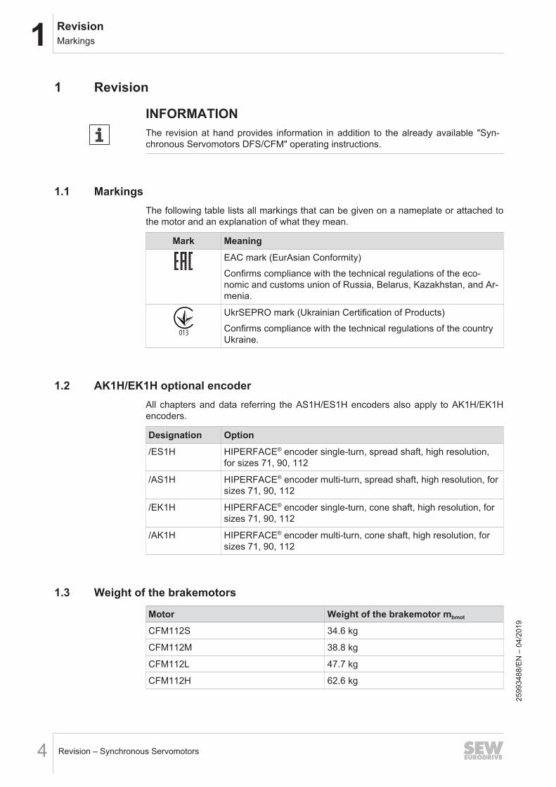
1.1 MarkingsThe following table lists all markings that can be given on a nameplate or attached tothe motor and an explanation of what they mean.
Mark MeaningEAC mark (EurAsian Conformity)Confirms compliance with the technical regulations of the eco-nomic and customs union of Russia, Belarus, Kazakhstan, and Ar-menia.
013
UkrSEPRO mark (Ukrainian Certification of Products)Confirms compliance with the technical regulations of the countryUkraine.
1.2 AK1H/EK1H optional encoderAll chapters and data referring the AS1H/ES1H encoders also apply to AK1H/EK1Hencoders.
Designation Option/ES1H HIPERFACE® encoder single-turn, spread shaft, high resolution,
for sizes 71, 90, 112
/AS1H HIPERFACE® encoder multi-turn, spread shaft, high resolution, forsizes 71, 90, 112
/EK1H HIPERFACE® encoder single-turn, cone shaft, high resolution, forsizes 71, 90, 112
/AK1H HIPERFACE® encoder multi-turn, cone shaft, high resolution, forsizes 71, 90, 112
1.3 Weight of the brakemotors
Motor Weight of the brakemotor mbmot
CFM112S 34.6 kg
CFM112M 38.8 kg
CFM112L 47.7 kg
CFM112H 62.6 kg
2599
3488
/EN
– 0
4/20
19
1RevisionTechnical data of the BR brake
Revision – Synchronous Servomotors 5
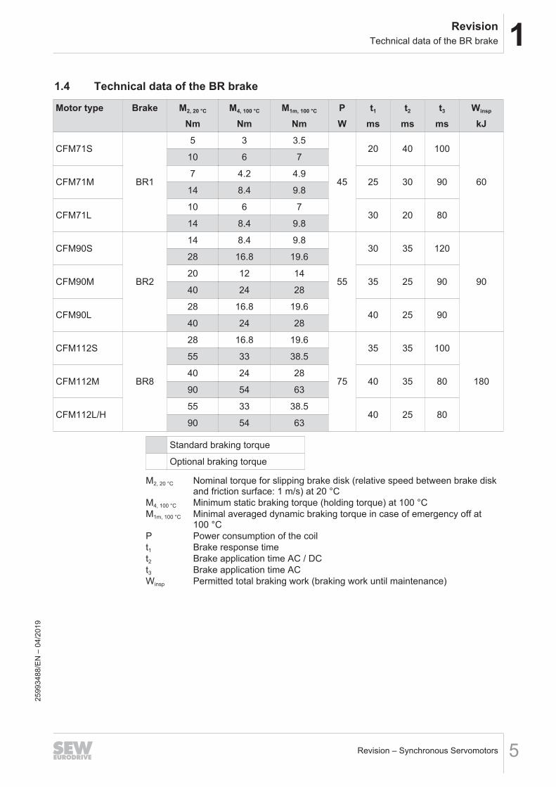
1.4 Technical data of the BR brake
Motor type Brake M2, 20 °C
NmM4, 100 °C
NmM1m, 100 °C
NmPW
t1
mst2
mst3
msWinsp
kJ
CFM71S
BR1
5 3 3.5
45
20 40 100
60
10 6 7
CFM71M7 4.2 4.9
25 30 9014 8.4 9.8
CFM71L10 6 7
30 20 8014 8.4 9.8
CFM90S
BR2
14 8.4 9.8
55
30 35 120
90
28 16.8 19.6
CFM90M20 12 14
35 25 9040 24 28
CFM90L28 16.8 19.6
40 25 9040 24 28
CFM112S
BR8
28 16.8 19.6
75
35 35 100
180
55 33 38.5
CFM112M40 24 28
40 35 8090 54 63
CFM112L/H55 33 38.5
40 25 8090 54 63
Standard braking torque
Optional braking torque
M2, 20 °C Nominal torque for slipping brake disk (relative speed between brake diskand friction surface: 1 m/s) at 20 °C
M4, 100 °C Minimum static braking torque (holding torque) at 100 °CM1m, 100 °C Minimal averaged dynamic braking torque in case of emergency off at
100 °CP Power consumption of the coilt1 Brake response timet2 Brake application time AC / DCt3 Brake application time ACWinsp Permitted total braking work (braking work until maintenance)
2599
3488
/EN
– 0
4/20
19
1 RevisionNew temperature sensor /PK
Revision – Synchronous Servomotors6
1.5 New temperature sensor /PKThe temperature sensor /PK replaces the previous temperature sensor /KY.
INFORMATIONMake sure the used inverter has the relevant evaluation electronics for the PK(PT1000) temperature sensor.
1.5.1 Type designation/PK
1.5.2 DescriptionThermal motor protection in combination with the corresponding evaluation electronicsprevents the motor from overheating and consequently from being damaged. A tem-perature sensor provides only indirect protection as only one sensor value is determ-ined.The /PK design consists of a platinum sensor PT1000 installed in one of the three mo-tor windings. Unlike the /KY semiconductor sensor, the platinum sensor has an almostlinear characteristic curve and is more accurate. The frequency inverter can take onthe function of motor protection via the /PK, when it is used in combination with a fre-quency inverter containing the thermal motor model.
2599
3488
/EN
– 0
4/20
19
1RevisionNew temperature sensor /PK
Revision – Synchronous Servomotors 7
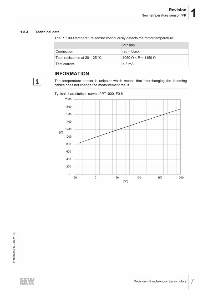
1.5.3 Technical dataThe PT1000 temperature sensor continuously detects the motor temperature.
PT1000Connection red – black
Total resistance at 20 – 25 °C 1050 Ω < R < 1150 Ω
Test current < 3 mA
INFORMATIONThe temperature sensor is unipolar which means that interchanging the incomingcables does not change the measurement result.
Typical characteristic curve of PT1000, F0.6
0
200
400
600
800
1000
1200
1400
1600
1800
2000
-50 0 50 100 150 200
[Ω]
[°C]
2599
3488
/EN
– 0
4/20
19
1 RevisionElectrical installation
Revision – Synchronous Servomotors8
1.6 Electrical installation1.6.1 Connecting the motor via terminal box
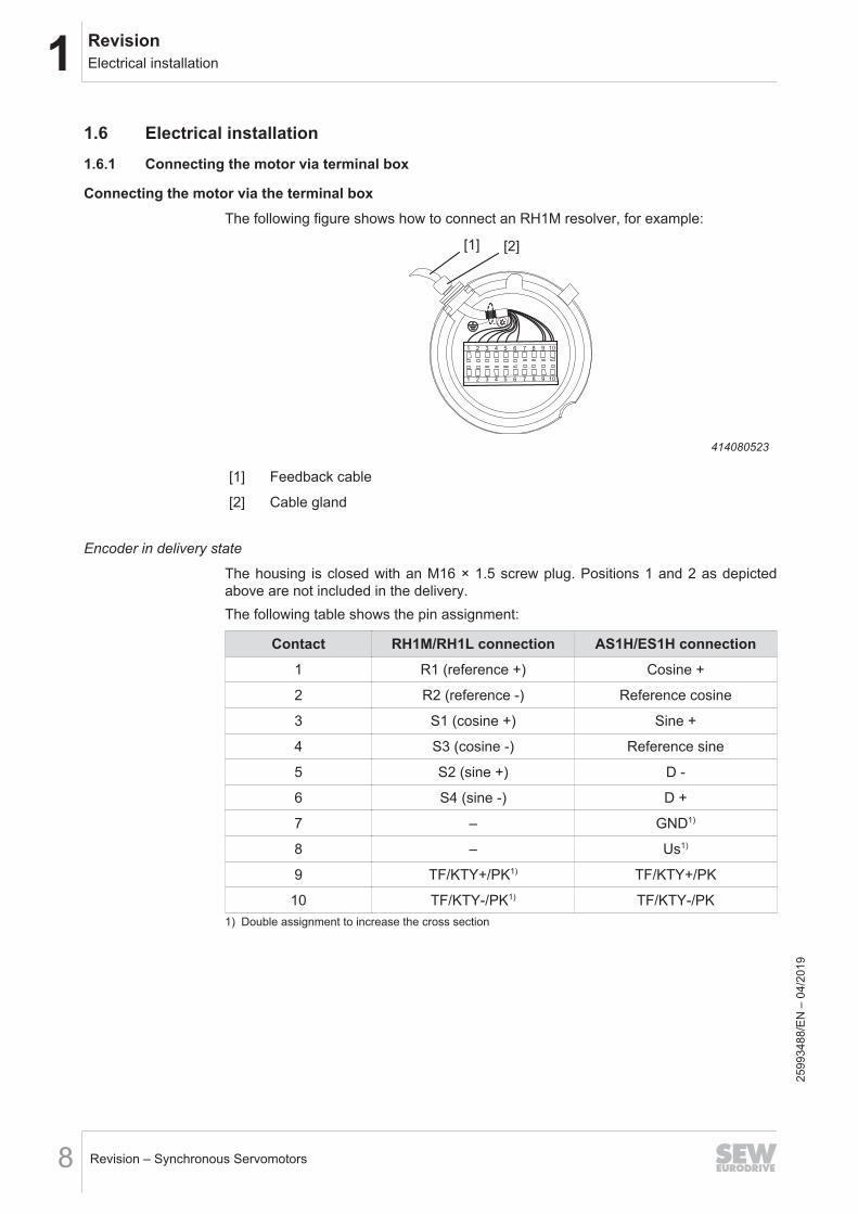
Connecting the motor via the terminal boxThe following figure shows how to connect an RH1M resolver, for example:
[1] [2]
1 2 3 4 5 6 7 8 9 10
1 2 3 4 5 6 7 8 9 10
414080523
[1] Feedback cable
[2] Cable gland
Encoder in delivery state
The housing is closed with an M16 × 1.5 screw plug. Positions 1 and 2 as depictedabove are not included in the delivery.The following table shows the pin assignment:
Contact RH1M/RH1L connection AS1H/ES1H connection1 R1 (reference +) Cosine +
2 R2 (reference -) Reference cosine
3 S1 (cosine +) Sine +
4 S3 (cosine -) Reference sine
5 S2 (sine +) D -
6 S4 (sine -) D +
7 – GND1)
8 – Us1)
9 TF/KTY+/PK1) TF/KTY+/PK
10 TF/KTY-/PK1) TF/KTY-/PK1) Double assignment to increase the cross section
2599
3488
/EN
– 0
4/20
19
1RevisionBrake controls with functional control input
Revision – Synchronous Servomotors 9
1.7 Brake controls with functional control inputIn addition to the voltage supply, the optional brake controls of the BMK., BMKB. andBMV. series offer a control input for a DC 24 V signal with which the brakes can beswitched via a PLC.It is a purely functional input that is not "functionally safe" with respect to safety tech-nology.Due to their operating principle, fault statuses may occur with these devices that leadto unintentional ongoing brake release, even if the control voltage has been switchedoff.
WARNINGUnintentional ongoing brake release due to unrecognized malfunction of the brakecontrol.Severe or fatal injuries, e.g. due to falling hoist or extended coasting.• Always disconnect all poles of the supply and control voltage for hoists and hoist-
like applications.• Ensure that a malfunction of the control input can be detected through additional,
suitable diagnostic measures e.g. by monitoring the braking current to meet highsafety and reliability requirements.
• Use the BST.. brake control for functional safety applications.• If you have any questions regarding the handling of the control input, contact
SEW‑EURODRIVE.
2599
3488
/EN
– 0
4/20
19
1 RevisionAppendix
Revision – Synchronous Servomotors10
1.81.8.1
AppendixWiring diagram for CFM motors with signal plug connector
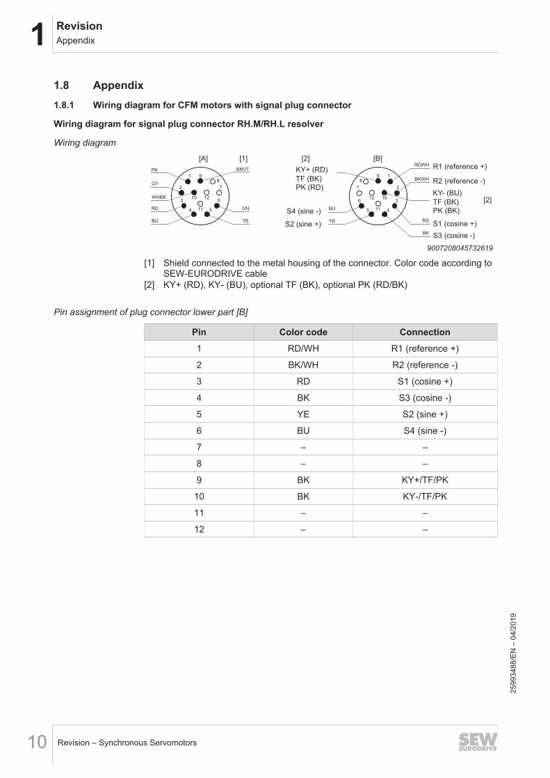
Wiring diagram for signal plug connector RH.M/RH.L resolver
Wiring diagram
1 98
2
10 12
7
3
4 5
6
11
GY
RD
BU
BNVT
GN
YE
PK
WHBK
198
2
1012
7
3
45
6
11
BKWH
RD
BU
YE
RDWH
BK
R1 (reference +)
R2 (reference -)
[2]
S1 (cosine +)
S3 (cosine -)
S4 (sine -)
S2 (sine +)
KY+ (RD)
[2] [B][1][A]
TF (BK)PK (RD)
KY- (BU)
TF (BK)PK (BK)
9007208045732619
[1] Shield connected to the metal housing of the connector. Color code according toSEW‑EURODRIVE cable
[2] KY+ (RD), KY- (BU), optional TF (BK), optional PK (RD/BK)
Pin assignment of plug connector lower part [B]
Pin Color code Connection1 RD/WH R1 (reference +)
2 BK/WH R2 (reference -)
3 RD S1 (cosine +)
4 BK S3 (cosine -)
5 YE S2 (sine +)
6 BU S4 (sine -)
7 – –
8 – –
9 BK KY+/TF/PK
10 BK KY-/TF/PK
11 – –
12 – –
2599
3488
/EN
– 0
4/20
19
1RevisionAppendix
Revision – Synchronous Servomotors 11
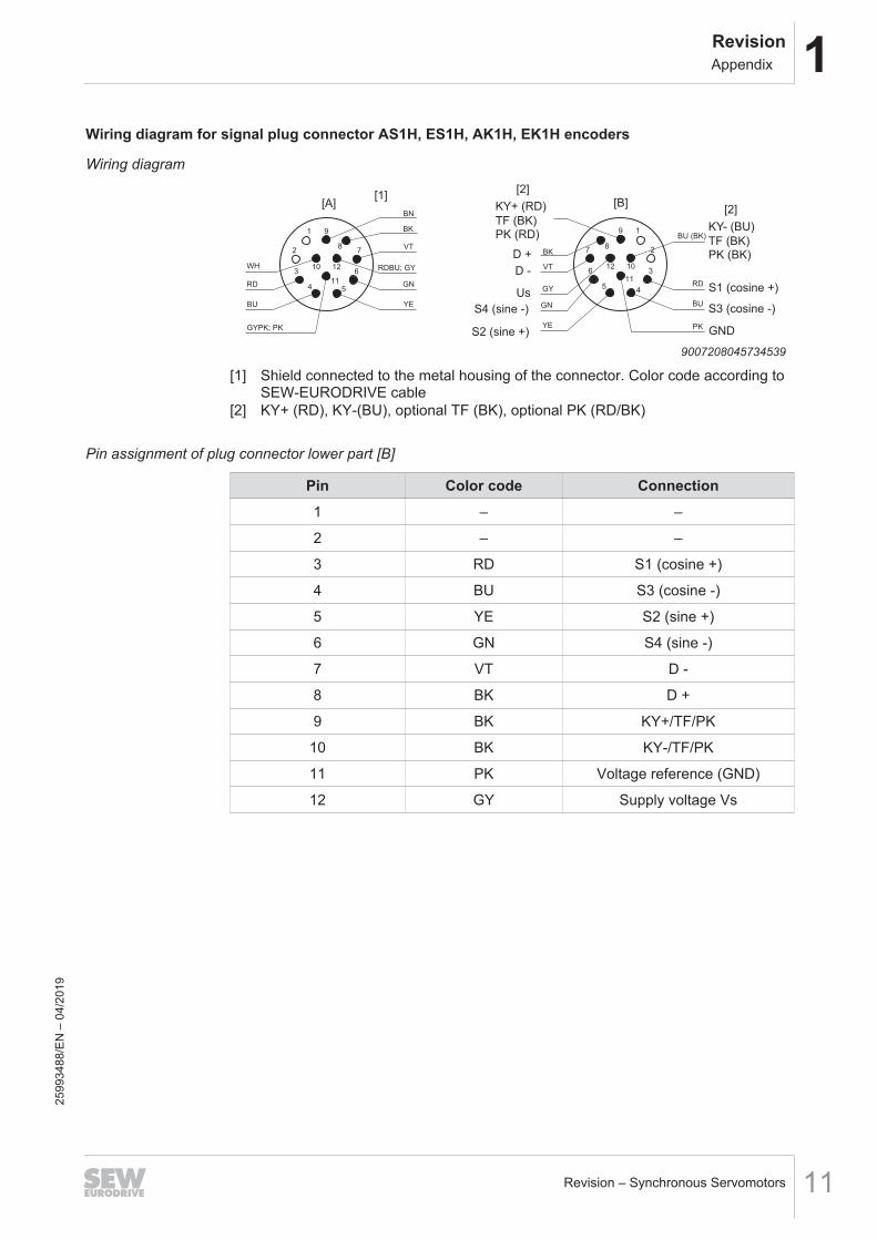
Wiring diagram for signal plug connector AS1H, ES1H, AK1H, EK1H encoders
Wiring diagram
1 9
82
10 12
7
3
4 5
6
11 GNRD
BU
BN
RDBU; GY
YE
VT
WH
GYPK; PK
BK
BU
19
82
1012
7
3
45
611
RD
GN
YE
BK
VT
GY
PK
BU (BK)
[A][1]
[2][B]
[2]
S1 (cosine +)
S3 (cosine -)
GNDS2 (sine +)
S4 (sine -)
Us
D -
D +
KY+ (RD)
TF (BK)PK (RD)
KY- (BU)
TF (BK)PK (BK)
9007208045734539
[1] Shield connected to the metal housing of the connector. Color code according toSEW‑EURODRIVE cable
[2] KY+ (RD), KY-(BU), optional TF (BK), optional PK (RD/BK)
Pin assignment of plug connector lower part [B]
Pin Color code Connection1 – –
2 – –
3 RD S1 (cosine +)
4 BU S3 (cosine -)
5 YE S2 (sine +)
6 GN S4 (sine -)
7 VT D -
8 BK D +
9 BK KY+/TF/PK
10 BK KY-/TF/PK
11 PK Voltage reference (GND)
12 GY Supply voltage Vs
2599
3488
/EN
– 0
4/20
19


SEW-EURODRIVE—Driving the world
SEW-EURODRIVE GmbH & Co KGErnst-Blickle-Str. 4276646 BRUCHSALGERMANYTel. +49 7251 75-0Fax +49 7251 [email protected]