Synchronous generators
20
Synchronous Generators Workshop on Basic Electrical Engineering, held at VVCE, Mysuru, on 30-April-2016 R S Ananda Murthy Associate Professor Department of Electrical & Electronics Engineering, Sri Jayachamarajendra College of Engineering, Mysore 570 006 R S Ananda Murthy Synchronous Generators
-
Upload
rsamurti -
Category
Engineering
-
view
592 -
download
3
Transcript of Synchronous generators
Synchronous GeneratorsWorkshop on Basic Electrical Engineering, held at
VVCE, Mysuru, on 30-April-2016
R S Ananda Murthy
Associate ProfessorDepartment of Electrical & Electronics Engineering,
Sri Jayachamarajendra College of Engineering,Mysore 570 006
R S Ananda Murthy Synchronous Generators

Learning Outcomes
After completing this lecture the student should be able to –Describe the principle of operation of an alternator.Describe different types of construction of alternators.List the advantages of rotating field type of alternators.State the reasons for distributing armature conductors inslots.State the meaning of pitch factor, distribution factor, andwinding factor in respect of armature winding of alternators.Find the frequency of the generated E.M.F.Calculate the generated E.M.F. in the alternator taking intoaccount distribution factor and pitch factor.
R S Ananda Murthy Synchronous Generators

Photographs of Practical Generators
Horizontal shaft type, typically driven by diesel engine.
R S Ananda Murthy Synchronous Generators

Photographs of Practical Generators
Vertical shaft type, typically driven by water turbine.
R S Ananda Murthy Synchronous Generators

Photographs of Practical Generators
Horizontal shaft, turbo-alternator, driven by steam turbine.
R S Ananda Murthy Synchronous Generators

Principle of Operation of Synchronous Generator
A1
A2
B1B2
C1
C2
StationaryArmature
RotatingField Coil
D.C.Supply
S N
A1
A2
B1
B2
C1
C2
Stator
Rotor
When the poles on the rotor, driven by prime mover, move pastthe stator conductors, due to the relative motion of conductorswith respect to the poles, the magnetic flux lines are cut by theconductors and voltage is induced in them.
R S Ananda Murthy Synchronous Generators
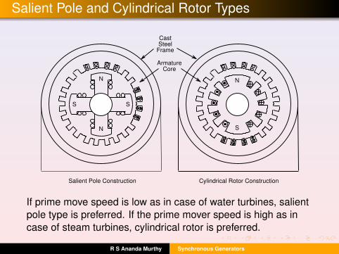
Salient Pole and Cylindrical Rotor Types
.
CastSteel
Frame
ArmatureCore
N
N
S S
N
S
Salient Pole Construction Cylindrical Rotor Construction
... .. ..
.... .. ..
If prime move speed is low as in case of water turbines, salientpole type is preferred. If the prime mover speed is high as incase of steam turbines, cylindrical rotor is preferred.
R S Ananda Murthy Synchronous Generators

Advantages of Rotating Field Construction
The coil connections can be made easily and securely onthe stator than on the rotor.If the armature winding is placed on the rotor, then, threeslip rings would be required where as if the poles areplaced on the rotor, only two slip rings designed to carrylow power for the field winding are required.Transferring large armature power through brush and slipring causes them to wear out frequently which is preventedif the armature is stationary.
R S Ananda Murthy Synchronous Generators

Advantages of Rotating Field Construction
As the generated voltage is 11 kV or above, armaturewinding requires thicker insulation which is difficult todesign if the armature is on the rotor.Field winding is lighter than armature winding andtherefore it is preferable to place it on the rotor.In very big synchronous generators, forced hydrogencooling of armature winding is employed which can beconveniently implemented if the armature is stationary.
R S Ananda Murthy Synchronous Generators

Reasons for Using Distributed Winding
Armature winding in practical generators is uniformly distributedin many slots for the following reasons —
It is difficult to put all the conductors of a phase winding inone or two slots.Distributed winding reduces harmonics in the generatedvoltage and makes the waveform closer to sinusoidalshape.Distributed winding helps in more uniform heat distributionand cooling and thus helps in preventing insulation failuredue to excessive heat in the winding.
R S Ananda Murthy Synchronous Generators
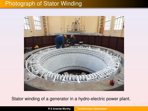
Photograph of Stator Winding
Stator winding of a generator in a hydro-electric power plant.
R S Ananda Murthy Synchronous Generators

Armature Winding Coils
P Q P Q
Full Pitched Coil Short Pitched Coil
A1 A2 A1 A2
Overhang
Coil Span
CoilSide
In practical generators, short pitched coils are used to minimizethe length of overhangs and also to reduce harmonics in thegenerated voltage.
R S Ananda Murthy Synchronous Generators

Pitch Factor (Kp) of Armature Winding
Due to short pitched coil, the magnitude of E.M.F. induced e willbe slightly reduced when compared to a full pitched coil. For ashort pitched coil, the pitch factor is defined as
Kp =Voltage generated in a short pitched coilVoltage generated in a full pitched coil
(1)
Formula for Kp is
Kp = cosβ
2(2)
where β is the angle in electrical degrees by which the coil isshort pitched as shown in the previous slide. Typically Kp isabout 0.9 in a practical generator.
R S Ananda Murthy Synchronous Generators
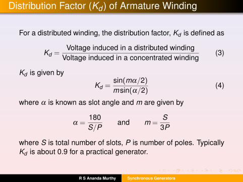
Distribution Factor (Kd ) of Armature Winding
For a distributed winding, the distribution factor, Kd is defined as
Kd =Voltage induced in a distributed winding
Voltage induced in a concentrated winding(3)
Kd is given by
Kd =sin(mα/2)
msin(α/2)(4)
where α is known as slot angle and m are given by
α =180S/P
and m =S
3P
where S is total number of slots, P is number of poles. TypicallyKd is about 0.9 for a practical generator.
R S Ananda Murthy Synchronous Generators

Frequency of Generated E.M.F.
When a conductor moves past a pair of poles, one cycle ofsinusoidal voltage is completed. If P = total number of poles inthe machine, then,
Number of cycles per revolution =P2
(5)
If N = R.P.M. of the motor, then, the rotor makes N/60 R.P.S.Hence, the frequency of the induced E.M.F. is given by
f =P2× N
60=
PN120
Hz (6)
R S Ananda Murthy Synchronous Generators

Equation for Induced E.M.F. in an Alternator
If P = number of poles in the machine, and Φ = flux per pole,magnetic flux cut by a conductor in one revolution of the rotor= PΦ. If N is the R.P.M., then, time taken by the rotor to makeone revolution = 60/N seconds. Therefore,
Flux cut per second by a conductor =PΦ
60/N
But average induced E.M.F. in a conductor = flux cut persecond. Therefore
Average induced E.M.F. in a conductor =PΦN
60
R S Ananda Murthy Synchronous Generators

Equation for Induced E.M.F. in an Alternator
If T = total number of turns connected in series per phase, andsince each turn will have two conductors, we haveZ = Total number of conductors in series per phase = 2T . So,
Average E.M.F. induced per phase = |Eav |=PΦN
60·2T
The air gap flux in the generator will have more or lesssinusoidal distribution. Then, the induced E.M.F. in each phasewill also be sinusoidal. For a sinusoidal waveform we have
Form Factor =|Eph||Eav |
= 1.11
where Eph = R.M.S. value of the induced voltage per phase.
R S Ananda Murthy Synchronous Generators

Equation for Induced E.M.F. in an Alternator
Therefore, the R.M.S. voltage induced per phase is
|Eph|= 1.11× PΦN60×2T =
2.22PΦNT60
(7)
But the frequency of the induced E.M.F. is given by
f =PN120
=⇒ 2f =PN60
Substituting this in Eq. (7) we get
|Eph|= 4.44ΦfT Volts
R S Ananda Murthy Synchronous Generators

Equation for Induced E.M.F. in an Alternator
In a practical machine the armature winding is evenlydistributed in the slots and short pitched coils are used. Due tothis, the induced E.M.F. is slightly reduced by a factor Kw whereKw = KpKd is known as the winding factor. So, the inducedE.M.F. in an actual machine is given by
|Eph|= 4.44ΦfTKw Volts (8)
Since the three coils in the armature winding of a practicalgenerator are always star connected, the line voltage at theterminals of the synchronous generator is given by
|E |=√
3×|Eph| (9)
R S Ananda Murthy Synchronous Generators

License
This work is licensed under aCreative Commons Attribution 4.0 International License.
R S Ananda Murthy Synchronous Generators


![Lecture 7 - Synchronous Generators[1]](https://static.fdocuments.in/doc/165x107/552639fd550346586f8b4b79/lecture-7-synchronous-generators1.jpg)