
Synchronizing real and predicte d synthetic video imagery ...lyons/Lyons SPIE IRCV 2010.pdf ·...
8
Synchronizing real and predicted synthetic video imagery for localization of a robot to a 3D environment Damian M. Lyons* a , Sirhan Chaudhry* a , D. Paul Benjamin b a Fordham University, Robotics and Computer Laboratory, Bronx NY 10458; b PACE University, Department of Computer Science, New York NY 10023 ABSTRACT A mobile robot moving in an environment in which there are other moving objects and active agents, some of which may represent threats and some of which may represent collaborators, needs to be able to reason about the potential future behaviors of those objects and agents. In previous work, we presented an approach to tracking targets with complex behavior, leveraging a 3D simulation engine to generate predicted imagery and comparing that against real imagery. We introduced an approach to compare real and simulated imagery using an affine image transformation that maps the real scene to the synthetic scene in a robust fashion. In this paper, we present an approach to continually synchronize the real and synthetic video by mapping the affine transformation yielded by the real/synthetic image comparison to a new pose for the synthetic camera. We show a series of results for pairs of real and synthetic scenes containing objects including similar and different scenes. Keywords: Cognitive robotics, robot simulation, synthetic video, motion detection, computer vision, robot localization. 1. INTRODUCTION A goal of Cognitive Robotics is to build robot systems capable of reasoning about all the kinds of complex phenomena that occur in everyday, real-world interactions. We have developed an approach to this problem based on using an open source 3D game engine. Informally, the simulation can act as the ‘imagination’ of the robot, allowing it to carry out a particular kind of thought experiment: allowing the simulated world to run faster than the real world for the purposes of prediction. A key novelty of our approach is that the output of the game engine is a synthetic ‘image’ of the predicted world, which can be compared directly to the image from the robot’s visual sensor. In this way, problem solving becomes integrated and part of the robot’s perceptual processes. Comparing a graphical, synthetic image and real image of the same scene poses many problems; in previous work [11], we propose an approach called the match-mediated difference approach that allows for effective comparisons of synthetic and real images of similar scenes, even scenes with objects added or removed. In this paper, we integrate the match-mediated difference approach intro a control loop that allows a robot to synchronize its camera pose in the synthetic world with the actual camera pose. Section 3 presents an overview of the components of the integrated simulation/robot system and presents the synchronization loop. Section 4 presents results showing the performance of the synchronization for various pose error and gain settings, including views with unexpected or missing objects. 2. LITERATURE REVIEW It has been proposed that cognitive functions such as anticipation and planning operate through a process of internal simulation of actions and environment [13]. Indeed there is a history in the field of Artificial Intelligence of using ‘simulated action’ as an algorithmic search procedure, e.g., game trees, though such an approach typically had problematic computational complexity. Shanahan [13] proposes a large-scale neurologically plausible architecture that allows for direct action (similar to a behavior-based approach) and also ‘higher-order’ or ‘internally looped’ actions that correspond to the ‘rehearsal’ or simulation of action without overt motion. The Polybot architecture proposed by Cassimatis et al. [5], and based on his Polyscheme cognitive architecture, implements planning and reasoning as sequences of ‘mental’ simulations that include perceptive and reactive subcomponents. The simulations include not just the effect of actions, but also the understood ‘laws’ of physics (e.g., will a falling object continue to fall) and are implemented as a collection of specialist modules that deliberate on propositions of relevance to the robot. Please verify that (1) all pages are present, (2) all figures are acceptable, (3) all fonts and special characters are correct, and (4) all text and figures fit within the margin lines shown on this review document. Return to your MySPIE ToDo list and approve or disapprove this submission. 7539 - 27 V. 1 (p.1 of 8) / Color: No / Format: Letter / Date: 2009-11-17 12:46:46 AM SPIE USE: ____ DB Check, ____ Prod Check, Notes:
Transcript of Synchronizing real and predicte d synthetic video imagery ...lyons/Lyons SPIE IRCV 2010.pdf ·...

Synchronizing real and predicted synthetic video imagery for localization of a robot to a 3D environment
Damian M. Lyons*a, Sirhan Chaudhry*a, D. Paul Benjaminb
aFordham University, Robotics and Computer Laboratory, Bronx NY 10458; bPACE University, Department of Computer Science, New York NY 10023
ABSTRACT
A mobile robot moving in an environment in which there are other moving objects and active agents, some of which may represent threats and some of which may represent collaborators, needs to be able to reason about the potential future behaviors of those objects and agents. In previous work, we presented an approach to tracking targets with complex behavior, leveraging a 3D simulation engine to generate predicted imagery and comparing that against real imagery. We introduced an approach to compare real and simulated imagery using an affine image transformation that maps the real scene to the synthetic scene in a robust fashion. In this paper, we present an approach to continually synchronize the real and synthetic video by mapping the affine transformation yielded by the real/synthetic image comparison to a new pose for the synthetic camera. We show a series of results for pairs of real and synthetic scenes containing objects including similar and different scenes.
Keywords: Cognitive robotics, robot simulation, synthetic video, motion detection, computer vision, robot localization.
1. INTRODUCTION A goal of Cognitive Robotics is to build robot systems capable of reasoning about all the kinds of complex
phenomena that occur in everyday, real-world interactions. We have developed an approach to this problem based on using an open source 3D game engine. Informally, the simulation can act as the ‘imagination’ of the robot, allowing it to carry out a particular kind of thought experiment: allowing the simulated world to run faster than the real world for the purposes of prediction. A key novelty of our approach is that the output of the game engine is a synthetic ‘image’ of the predicted world, which can be compared directly to the image from the robot’s visual sensor. In this way, problem solving becomes integrated and part of the robot’s perceptual processes.
Comparing a graphical, synthetic image and real image of the same scene poses many problems; in previous work [11], we propose an approach called the match-mediated difference approach that allows for effective comparisons of synthetic and real images of similar scenes, even scenes with objects added or removed. In this paper, we integrate the match-mediated difference approach intro a control loop that allows a robot to synchronize its camera pose in the synthetic world with the actual camera pose. Section 3 presents an overview of the components of the integrated simulation/robot system and presents the synchronization loop. Section 4 presents results showing the performance of the synchronization for various pose error and gain settings, including views with unexpected or missing objects.
2. LITERATURE REVIEW It has been proposed that cognitive functions such as anticipation and planning operate through a process of
internal simulation of actions and environment [13]. Indeed there is a history in the field of Artificial Intelligence of using ‘simulated action’ as an algorithmic search procedure, e.g., game trees, though such an approach typically had problematic computational complexity. Shanahan [13] proposes a large-scale neurologically plausible architecture that allows for direct action (similar to a behavior-based approach) and also ‘higher-order’ or ‘internally looped’ actions that correspond to the ‘rehearsal’ or simulation of action without overt motion. The Polybot architecture proposed by Cassimatis et al. [5], and based on his Polyscheme cognitive architecture, implements planning and reasoning as sequences of ‘mental’ simulations that include perceptive and reactive subcomponents. The simulations include not just the effect of actions, but also the understood ‘laws’ of physics (e.g., will a falling object continue to fall) and are implemented as a collection of specialist modules that deliberate on propositions of relevance to the robot.
Please verify that (1) all pages are present, (2) all figures are acceptable, (3) all fonts and special characters are correct, and (4) all text and figures fit within themargin lines shown on this review document. Return to your MySPIE ToDo list and approve or disapprove this submission.
7539 - 27 V. 1 (p.1 of 8) / Color: No / Format: Letter / Date: 2009-11-17 12:46:46 AM
SPIE USE: ____ DB Check, ____ Prod Check, Notes:

In previous work, we have described our approach to this problem which uses a 3D game engine as a world simulation tool. The growth of the video game industry has contributed to the ready availability of good 3D simulation environments [9]. Although 3D simulation has been used in robotics [1][7] that approach is focused on providing ready interleaved access to simulation or robot control to a programmer. In contrast, our use of simulation is as an intrinsic part of the robot control itself, not as an aid to the programmer.
In the assembly and task planning field, the integration of simulation into the reasoning process has been investigated [17]; the integration was achieved by allowing the planning module access to the internal data structures of the simulation. However, that approach is difficult to use in robotics because there is no general way to link the data structures of a simulation with the sensory apparatus of the robot. This is strongly related to the problem of the perceptual anchoring of symbols [6]. We have developed a unique approach to this problem by allowing the simulation to communicate to the robot in a common language – a visual image of the world.
In [11], we have described an approach to this problem based on comparing the visual input of the robot with imagery generated from a dynamic 3D world model and directing discrepancies to the robot’s SOAR-based cognitive system. Integration of Video and 3D imagery has been considered in applications such as predictive teleoperation [4]. Our problem is different in that it requires comparing the synthetic and real imagery to look for differences between actual and predicted object behaviors. Comparing the synthetic imagery from the world model with imagery from the vision system poses a number of problems – a simple difference operation between real and synthetic images is not very effective. We have developed an approach called the Match-Mediated Difference (MMD) image that allows effective comparison of real and synthetic views of a scene. The MMD image operation also allows the real and synthetic camera views to be synchronized, a robot localization operation, and this is the focus of the current paper.
3. APPROACH 3.1 Experimental Scenario
Our objective is to allow a cognitive robot system to reason about complex physical phenomena in a manner that makes it easy to apply the results of the reasoning to robot sensing and action. For the task where a robot must predict the location of a moving object in order to intercept it, e.g., intercept a moving soccer ball, a behavior-based approach that includes visual tracking of the ball can yield a robust solution (e.g., [12][14]). However, if the problem is expanded to include the ball moving towards a wall or another unexpected agent then since the dynamics used in tracking a ball typically does not include information about bouncing off walls or other agents, tracking and prediction becomes more challenging. While a fast tracking system might reacquire the ball target after the bounce, it certainly will not be able to predict the bounce, and any action that the robot takes before the bounce will be predicated on the ball continuing its observed path. This puts the robot in the position of always playing ‘catch-up’ with the ball instead of accurately predicting where the ball will be and moving there. This same issue arises whenever a robot is operating in a complex dynamic environment, for example, an urban search and rescue robot moving on a semi-stable pile of rubble.
Figure 2: Experimental Scenario; (A) bouncing scenario, (B) Pioneer AT3, (C) scenario location.
We start with a relatively simple scenario (see Fig. 2): A robot is positioned facing a wall. A ball is rolled across the field of view of the robot ultimately bouncing from the wall. The robot needs to intercept the ball after the bounce. Additional objects are placed by the wall so that ball bounces in a complex manner.
(A) (B) (C)
Please verify that (1) all pages are present, (2) all figures are acceptable, (3) all fonts and special characters are correct, and (4) all text and figures fit within themargin lines shown on this review document. Return to your MySPIE ToDo list and approve or disapprove this submission.
7539 - 27 V. 1 (p.2 of 8) / Color: No / Format: Letter / Date: 2009-11-17 12:46:46 AM
SPIE USE: ____ DB Check, ____ Prod Check, Notes:

3.2 System Overview
Figure 1 shows the block diagram of the overall system. The core functionality of the system is in the four shaded boxes. The camera module generates an image of the environment as seen by the robot at pose Pr. The simulation module generates a synthetic view of the environment as predicted by the simulation with the robot at pose Ps. Both images are fed to the match-mediated difference module, which calculates the affine transform from one to the other producing an ‘error’ measure He and a match-mediated difference (MMD) image [11]. The error information is used to modify the pose of the simulation and improve the localization of the robot with respect to the simulation. The difference mask is used to determine what scene elements are not where they were expected (new objects, missing objects or misplaced objects).
Figure 1: System Block Diagram
The four shaded boxes comprise the autonomous core of the system and function in two modes:
1. Synchronization Mode: In synchronization mode, the system continually compares one image from the camera module with one image from the simulation module generating an error homograpy He and an MMD image. The error homograpy is used to calculate a new simulation pose Ps. The difference image is used to identify new, unexpectedly placed or missing scene elements. This information is used to add or remove simulation elements to improve the visual correspondence of the simulation with the environment. For example, an unexpected object will appear as a difference region. In response, an object will be introduced into the simulation at this position. The texture information from the difference region is then used to texture the surface of the object. The simulation is constrained to step through time at the same rate as the robot (“real-time”).
2. Prediction Mode: In prediction mode, the state of the simulation is first stored, then the simulation is allowed to
step through time at a faster rate than the robot (super “real-time”) for a specific duration. The synchronization with the camera module is disabled for the duration. At the end of the duration, the camera image is compared with the information from the camera module to extract predicted scene element locations. The current state of the simulation is then restored.
The interface between the behavior-based and SOAR levels of the system [2] is implemented using the concept
of a Perceptual Schema [2], acting as a visual marker[16] or anchor[6] that ties a scene element or elements to perceptual concepts that play a role in behaviors. Perceptual schema markers can be placed on real-scene elements and then track these elements, reporting information to the behaviors in which they play a role. They can also be placed on corresponding simulated scene elements, allowing for the easy extraction of predicted object behaviors when operating in prediction mode.
Behavior-based Network & SOAR
Camera Simulation
Synchronization
Match Mediated Difference
(MMD)
New, Missing, or Unexpected
Elements
Perceptual Schemas
Pr Ps
Synthetic Image
Visual Image
He
Prediction Request
Please verify that (1) all pages are present, (2) all figures are acceptable, (3) all fonts and special characters are correct, and (4) all text and figures fit within themargin lines shown on this review document. Return to your MySPIE ToDo list and approve or disapprove this submission.
7539 - 27 V. 1 (p.3 of 8) / Color: No / Format: Letter / Date: 2009-11-17 12:46:46 AM
SPIE USE: ____ DB Check, ____ Prod Check, Notes:

The focus of this paper is on the synchronization mode and correction of pose based on the error homography.
In the next four subsections, the simulation, MMD, camera and synchronization modules are presented in more detail.
3.3 The Simulation Module
Development in game-engine technology has progressed to the point where there are currently several fast, efficient open-source game engines (see [8] for a listing). We have selected OGRE [10] (Open source Graphics Rendering Engine) because it is a stable, good quality, open-source 3D engine with a large and active user community. OGRE is a multi platform 3D engine with fast, good-quality scene rendering (e.g., see Fig. 3 (A)). It is written in C++ and provides support for DirectX 9 and OpenGL hardware features. It has also been integrated with the commonly used Open Dynamics Engine (ODE). The version of OGRE/ODE used in this work is 1.6.1 ("Shoggoth").
(A) (B) (C) (D) (E)
Figure 3: Ogre Simulation; (A) example of Ogre rendering, (B) video image of lab wall , (C) Ogre simulation of lab wall with video texture map, (D) Ogre Simulation of wall and object,
and (E) simulation calibration target.
The scene manager in Ogre is used to construct a floor and wall similar to that in Fig. 2(A,C). To bootstrap the process, the video image from the camera looking at the wall (Fig. 3(B)) is used to produce texture maps for the wall and floor area (Fig. 3(C, D)). Once the system is bootstrapped, we plan to have additional texture extraction be automatic.
A camera in Ogre is a software device that allows the programmer to specify what view of the simulated world is presented as an image to the user. However, we treat the graphical image generated by the simulation camera as a synthetic visual input image. We set the camera location and orientation to correspond roughly to the location of the actual camera in the laboratory. To use the graphical camera information to correct the camera pose with respect to the real camera, we need to extract the graphical camera parameters. This is done by placing a simulated calibration target at various poses in the simulated scene (Fig. 3(E)) and using camera calibration routines from the open source OpenCV1 library to generate the intrinsic matrix for the simulation camera, Ks.
3.4 The Camera Module
The camera module reads an image from the camera on the robot and transmits it to the MMD module. Camera calibration is carried out by using the camera calibration routines from the open source OpenCV library to generate the intrinsic matrix for the real camera, Kr. Both real and synthetic images are transmitted to the MMD module to determine their similarity.
3.5 The Match-Mediated Difference (MMD) Module
If we just consider the camera misalignment issue, we can approximate the registration between the real and synthetic images by an affine transformation. If ps=(xx , ys) is a point on Is and pr=(xr , yr) is a point on Ir then we can say: pr = A ps + b, where A is a 2 × 2 rotation matrix and b a translation. If points of correspondence can be established between the real and synthetic images, then the affine parameters A and b can be estimated. Using the efficient corner detection library of Trajkovic & Hedley [14] corners were labeled in the real and synthetic images (e.g., Fig. 4(A, B) for the scene of Fig. 3(B)). The RANSAC algorithm was used to estimate the affine parameters A and b. The real image was transformed for registration with the synthetic image yielding I’r.
The thresholded difference operation | Is- I’r| is shown in Fig. 4(C). It can be seen that some of the sources of the difference error have been resolved by the transformation but not all, since there are other appearance differences between the real and synthetic images; the affine registration on its own is not sufficient. To address this, we will make 1 opencv.willowgarage.com
Please verify that (1) all pages are present, (2) all figures are acceptable, (3) all fonts and special characters are correct, and (4) all text and figures fit within themargin lines shown on this review document. Return to your MySPIE ToDo list and approve or disapprove this submission.
7539 - 27 V. 1 (p.4 of 8) / Color: No / Format: Letter / Date: 2009-11-17 12:46:46 AM
SPIE USE: ____ DB Check, ____ Prod Check, Notes:

the assumption that the image area around a point used to estimate the affine registration should be similar in both images. The better two matched points correspond between real and synthetic images, the more we will assume the two images should be similar. This approach was presented in detail in [11] and is briefly reviewed below.
(A) (B) (C)
Figure 4: Corners detected in real (A) and synthetic (B) scenes, real scene affine warped to synthetic scene using matched and thresholded difference image (C) with warped real and synthetic images.
Let pr and ps be two matched points in the real and synthetic images. We will consider one of the images to be
the primary image and construct the difference image in those image coordinates. In this paper we consider the synthetic image to be the primary image. Each match point p’ in the set of match points P will be in the image coordinates of the synthetic image. Its corresponding point in the real image will be given by the affine transform m( p’ ) = A p’ + b.
We will place a normalized Gaussian at each point p’ in the set of match points P and sum these over the image to create an image mask whose values correspond to the proximity of the image pixel to adjacent match points:
∑∈
−
Pp
v
p
pp
eSP '
2
'
2)'(
1||
1 (21)
where 'pS is the sum of the Gaussian for p’ over the entire image I and v a small, fixed variance parameter. If p is a point in the set of match points P, we define the match error e( p ) to be the distance between the two matched points p and m(p) in the primary image coordinates and define the normalized match quality q(p) to be the inverse of the match error normalized by the sum of all match errors. This is a measure of the quality of match p with respect to all the other matches, and we use this as a coefficient for the Gaussians in Eq. (2) to generate the match-mediated difference mask Im :
∑∈
−
=Pp
v
pm
pp
eS
pqP
pI'
2
'
2)'(
)'(||
1)( (2)
Figure 5(A) shows the match points for the running example superimposed on the absolute difference image| Is- I’r|. Fig. 5(B) shows the resultant gray level match-mediated difference mask. To calculate the match-mediated difference image using the match-mediated difference mask, we divide each point in the difference image by the corresponding point in the mask:
)(
|)(')(|)(pI
pIpIpIm
rsd
−= (3)
and the result for the running example is shown in Fig. 5(C) and thresholded in Fig. 5(D). (The thresholds used throughout are the same for all images). The resulting difference image shows only the edge of the common region in the primary (synthetic) and affine transformed secondary (real) image, allowing us to finally say that both images are of the same scene from different viewpoints.
(A) (B) (C) (D)
Figure 5: Absolute difference of warped real and synthetic images with overlaid match points (A) and MMD mask (B) calculated from (A). Match mediated absolute difference image (C) and thresholded difference image (D).
Please verify that (1) all pages are present, (2) all figures are acceptable, (3) all fonts and special characters are correct, and (4) all text and figures fit within themargin lines shown on this review document. Return to your MySPIE ToDo list and approve or disapprove this submission.
7539 - 27 V. 1 (p.5 of 8) / Color: No / Format: Letter / Date: 2009-11-17 12:46:46 AM
SPIE USE: ____ DB Check, ____ Prod Check, Notes:

3.6 The Synchronization Module
The synchronization module modifies the pose of the simulation camera Ps so that the synthetic and real views correspond more closely. The projection matrix for a camera image can be written as P = K [R | τ ], where K is the camera intrinsic matrix and [ R | τ ] the extrinsic matrix describing the pose of the camera with a rotation matrix R and a translation τ. Let the synthetic image projection matrix be given by Ps = Ks [ I | 0 ] and let the real image projection matrix be given by Pr = Kr [R | τ ]. In that case we can write the relationship between the error homography He produced by the MMD module and camera projection matrices as:
r
T
se KdnRKH ⎟⎟
⎠
⎞⎜⎜⎝
⎛−= − τ1 (4)
where n is the normal to the image plane and d is the depth of the image plane. Guerrero et al. [8] presents an algorithm to calculate R and τ (up to a scale) from eq. (4). In our case, the effect of translation is quite small in the bootstrapping case, since we have set the two cameras to approximately equivalent positions. We can simply eq (4) by removing the translation term. The estimate of the error homography by the MMD module is likely to contain some noise due to the selection and matching of corner points. For this reason, we use the following approach to set the simulated camera orientation at time t+1 based on the orientation at time t, Rs( t ), and the homography-derived rotation error multiplied by a linear gain, g<1:
)()()1( 1serss KHKgtRtR −=+ (5)
4. EXPERIMENTAL RESULTS The core functionality of the system (the four shaded boxes in Fig. 1) was evaluated by running the system with
a known rotation error between synthetic and real camera orientations and recording the results. Figure 6 shows a plot of the roll difference ϕ(t+1) – ϕ(t) versus iteration time step t for an initial roll error of 3.5 degrees. Plots for four different gain values in eq. (6) are shown (g=0.01, 0.05, 0.15, 0.2). The noise in the orientation estimate is especially clear for g=0.01. The system was unstable for g>0.2.
Roll Error during Synchronization
gain=0.02,0.05,0.25,0.2
0
0.5
1
1.5
2
2.5
3
3.5
4
1 21 41 61Iteration Step
Rol
l Err
or
g=0.01
g=0.05
g=0.15
g=0.2
Figure 6: Graph of the Roll Error versus Iteration step during synchronization for four values of gain for
an initial 3.5 degree error between synthetic and real images. Fig. 7 shows a series of images including the input images to and output images from the MMD module. Fig. 7
columns (A) and (B) are the real and synthetic images, the real image has been annotated with the corner points chosen for matching. Fig. 7. column (C) is the transformed real image, column (D) is the MMD mask and (E) the MMD image. Each row in Fig. 7 corresponds to a sample of images for t=5,10,20 during the 20 step synchronization of real and synthetic images starting with a 5 degree roll error. There are no scene element differences (new objects, missing objects, objects in different locations) between the synthetic and real images and the MMD image (Fig. 7 column (E)) is correspondingly empty for all rows. The principle difference is that the warped image (Fig. 7. column (C)) can be seen to gradually align from top row to bottom row as the simulation camera orientation is corrected using eq. (5).
Figure 8 shows a typical trace of the roll (Fig. 8(A)), pitch (Fig. 8(B)) and yaw (Fig. 8(C)) errors for an initial orientation error of 23 degrees in roll, 2.9 in pitch and 2.9 in yaw. The initial pitch and yaw values are relatively small compared to roll, since a larger pitch or yaw value will move the wall completely out of view. The rows from top to bottom in Fig. 8 shown the results for g=0.01, 0.1, 0.15 respectively. The graphs show that the implementation of eq. (5)
Please verify that (1) all pages are present, (2) all figures are acceptable, (3) all fonts and special characters are correct, and (4) all text and figures fit within themargin lines shown on this review document. Return to your MySPIE ToDo list and approve or disapprove this submission.
7539 - 27 V. 1 (p.6 of 8) / Color: No / Format: Letter / Date: 2009-11-17 12:46:46 AM
SPIE USE: ____ DB Check, ____ Prod Check, Notes:
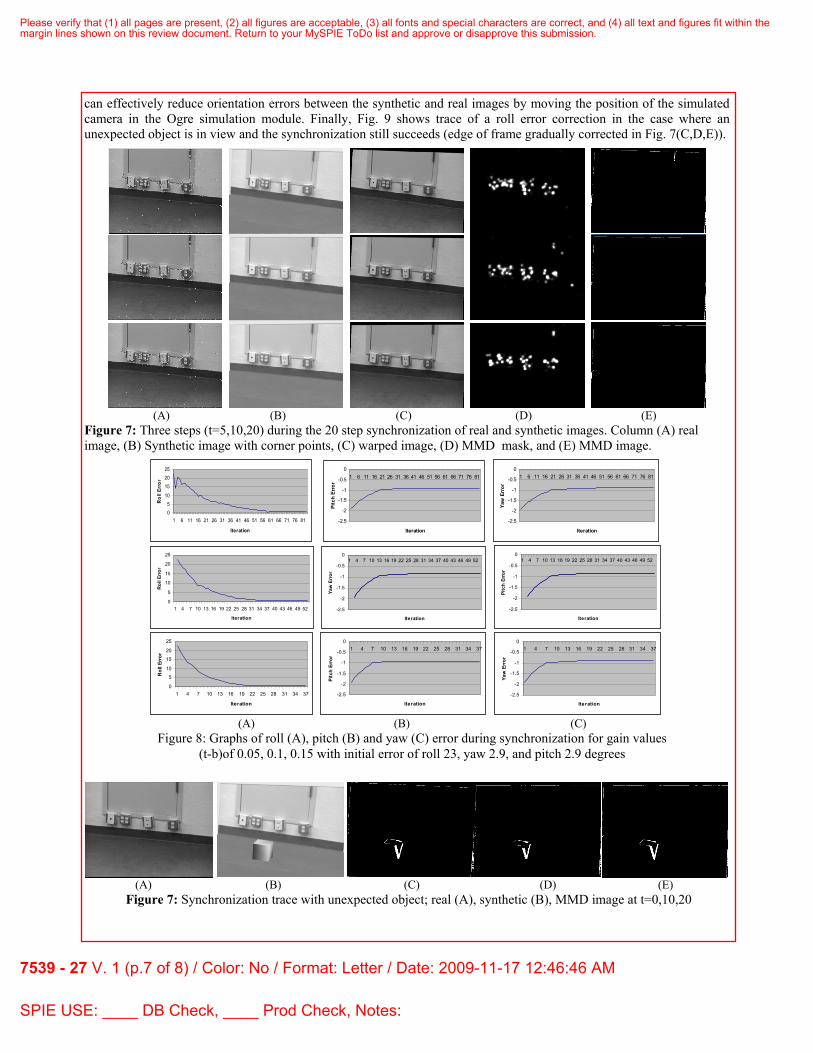
can effectively reduce orientation errors between the synthetic and real images by moving the position of the simulated camera in the Ogre simulation module. Finally, Fig. 9 shows trace of a roll error correction in the case where an unexpected object is in view and the synchronization still succeeds (edge of frame gradually corrected in Fig. 7(C,D,E)).
(A) (B) (C) (D) (E) Figure 7: Three steps (t=5,10,20) during the 20 step synchronization of real and synthetic images. Column (A) real image, (B) Synthetic image with corner points, (C) warped image, (D) MMD mask, and (E) MMD image.
(A) (B) (C) (D) (E)
Figure 7: Synchronization trace with unexpected object; real (A), synthetic (B), MMD image at t=0,10,20
05
10
152025
1 6 11 16 21 26 31 36 41 46 51 56 61 66 71 76 81
Iteration
Rol
l Err
or
-2.5
-2
-1.5
-1
-0.5
01 6 11 16 21 26 31 36 41 46 51 56 61 66 71 76 81
Iteration
Pitc
h Er
ror
-2.5
-2
-1.5
-1
-0.5
01 6 11 16 21 26 31 36 41 46 51 56 61 66 71 76 81
Iteration
Yaw
Err
or
0
5
10
15
20
25
1 4 7 10 13 16 19 22 25 28 31 34 37 40 43 46 49 52
Iteration
Rol
l Err
or
-2.5
-2
-1.5
-1
-0.5
01 4 7 10 13 16 19 22 25 28 31 34 37 40 43 46 49 52
Iteration
Yaw
Err
or
-2.5
-2
-1.5
-1
-0.5
01 4 7 10 13 16 19 22 25 28 31 34 37 40 43 46 49 52
Iteration
Pitc
h Er
ror
0
5
10
15
20
25
1 4 7 10 13 16 19 22 25 28 31 34 37
Iteration
Rol
l Err
or
-2.5
-2
-1.5
-1
-0.5
01 4 7 10 13 16 19 22 25 28 31 34 37
Iteration
Pitc
h Er
ror
-2.5
-2
-1.5
-1
-0.5
01 4 7 10 13 16 19 22 25 28 31 34 37
Iteration
Yaw
Err
or
(A) (B) (C)
Figure 8: Graphs of roll (A), pitch (B) and yaw (C) error during synchronization for gain values (t-b)of 0.05, 0.1, 0.15 with initial error of roll 23, yaw 2.9, and pitch 2.9 degrees
Please verify that (1) all pages are present, (2) all figures are acceptable, (3) all fonts and special characters are correct, and (4) all text and figures fit within themargin lines shown on this review document. Return to your MySPIE ToDo list and approve or disapprove this submission.
7539 - 27 V. 1 (p.7 of 8) / Color: No / Format: Letter / Date: 2009-11-17 12:46:46 AM
SPIE USE: ____ DB Check, ____ Prod Check, Notes:

5. SUMMARY We have proposed an approach to cognitive robotics in which a 3D engine can be used to predict complex object
behaviors. The perceptual grounding problem is addressed by having the simulation communicate with the robot’s sensory system through a common language – the visual image. In previous work, we developed the Motion-mediated difference (MMD) image to allow effective comparison of real and synthetic views of similar scenes. In this paper, we show how the MMD processing can be used to keep the simulated camera view synchronized with the actual camera view. Our results indicate that the simulated camera can be servoed in roll, pitch and yaw using the error homography information from the MMD processing. The approach works whether or not the MMD image is empty.
The next step in this work is the implementation and testing of the prediction mode of the system using the scenario presented in section 3.1. In order to accomplish this, the new object/missing object functionality will also need to be implemented. Although the MMD image allows the image region of difference (and hence video texture) to be quickly extracted, to add the scene element to the simulation, a scene location is also necessary. A ground plane assumption can be exploited to achieve this for the scenario in section 3.1, but in general, stereo or laser-ranging information is a more general solution.
REFERENCES
[1] Albrecht, S., J. Hertzberg, K. Lingemann, A. Nüchter, J. Sprickerhof, and S. Stiene. “Device Level Simulation of Kurt3D Rescue Robots,” Proc. 3rd Int. Workshop on Synthetic Simulation & Robotics to Mitigate Earthquake Disasters (SRMED 2006), June (2006)
[2] Arbib, M.A.,”The Handbook of Brain Theory and Neural Networks” (Ed. M.A. Arbib) MIT Press (2003). [3] Benjamin, D.P., Lonsdale, D., and Lyons, D.M., “Embodying a Cognitive Model in a Mobile Robot,”
Proceedings of the SPIE Conference on Intelligent Robots and Computer Vision, Boston, October (2006). [4] Burkert, T., and Passig, G., “Scene Model Acquisition for a Photo-Realistic Predictive Display,” Proceedings
of the Third International Conference on Humanoid Robots, October (2004). [5] Cassimatis, N., Trafton, J., Bugajska, M., Schulz, A., “Integrating cognition, perception and action through
mental simulation in robots” Robotics and Autonomous Systems N49, pp13-23 (2004). [6] Coradeschi, S., Saffiotti, A., “Perceptual Anchoring of Symbols for Action” Int. Joint. Conf. on AI, Aug 4-
10, Seattle WA (2001). [7] Diankov, R., and J. Kuffner, “OpenRAVE: A Planning Architecture for Autonomous Robotics,” Tech. report
CMU-RI-TR-08-34, Robotics Institute, Carnegie Mellon University, July (2008). [8] Guerrero, J., Martinez-Cantin, R., Sagues, C., “Visual map-less navigation based on homographies” Journal
of Robotic Systems V22 N10, pp.569-581 (2005). [9] Game Programmer’s Wiki: Game Engines, http://gpwiki.org/index.php/Game_Engines. [10] Open-source Graphics Rendering Engine (OGRE), http://www.ogre3d.org . [11] Lyons, D.M., and Benjamin, D.P., “Locating and Tracking Objects by Efficient Comparison of Real and
Predicted Synthetic Video Imagery,” Proceedings of the SPIE Conference on Intelligent Robots and Computer Vision, San Jose CA, Jan. (2009).
[12] Mantz, F., Pieter Jonker, “Behavior Based Perception for Soccer Robots,” in: Goro Obinata, Ashish Dutta, Nagoya University (Eds),Vision Systems Advanced Robotic Systems, Vienna, Austria, April (2007).
[13] M.P.Shanahan, A Cognitive Architecture that Combines Internal Simulation with a Global Workspace, Consciousness and Cognition, vol. 15 (2006), pages 433-449.
[14] Shen, W., Jafar Adibi, Rogelio Adobatti, Bonghan Cho, Ali Erdem, Hadi Moradi, Behnam Salemi, Sheila Tejada. "Autonomous Soccer Robots". Lecture Notes in Computer Science 1395, Springer-Verlag, (1998).
[15] Trajkovic, M., Hedley, M., “Fast Corner Detection,” Image and Vision Computing, (16) pp. 75-87 (1998) [16] G. Wasson, D. Kortenkamp, and E. Huber, “Integrating Active Perception with an Autonomous Robot
Architecture” Journal of Robotics and Autonomous Systems 29: 175-186 (1999) [17] Xiao, J., Zhang, L., “A Geometric Simulator SimRep for Testing the Replanning Approach toward
Assembly Motions in the Presence of Uncertainties,” IEEE Int. Symp. Assembly and Task Planning, (1995).
Please verify that (1) all pages are present, (2) all figures are acceptable, (3) all fonts and special characters are correct, and (4) all text and figures fit within themargin lines shown on this review document. Return to your MySPIE ToDo list and approve or disapprove this submission.
7539 - 27 V. 1 (p.8 of 8) / Color: No / Format: Letter / Date: 2009-11-17 12:46:46 AM
SPIE USE: ____ DB Check, ____ Prod Check, Notes: