Synchronized Robot Drumming with Neural...
7
Synchronized Robot Drumming with Neural Oscillators Shin'ya Kotosaka 1 Stefan Schaal 1,2 [email protected] [email protected] 1 Kawato Dynamic Brain Project (ERATO/JST), 2-2 Hikari-dai, Seika-cho, Soraku-gun, Kyoto 619-02, Japan 2 Computer Science and Neuroscience, University of Southern California, Los Angeles, CA 90089-2520 Abstract Sensorimotor integration and coordination is an impor- tant issue in both biological and biomimetic robotic sys- tems. In this paper, we investigate a ubiquitous case of sensorimotor coordination, the synchronization of rhythmic movement with an external rhythmic sound signal, a signal that, however, can change in frequency. The core of our techniques is a network of nonlinear os- cillators that can rapidly synchronize with the external sound, and that can generate smooth movement plans for our robot system, a full-body humanoid robot. In order to allow for both frequency synchronisation and phase control for a large range of external frequencies, we develop an automated method of adapting the pa- rameters of the oscillators. The applicability of our methods is exemplified in a drumming task. We demon- strate that our robot can achieve synchronization with an external drummer for a wide range of frequencies with minimal time delays when frequency shifts occur. 1. Introduction The coordination of movement with external sensory signals is a mode of motor control found commonly in the daily behaviors of humans, e.g., as in dancing, synchronization of locomotion with other humans, playing music, marching in a parade, playing with balls, etc. In our work on humanoid robots, we are in- terested in equipping autonomous robots with similar sensorimotor skills. Traditional methods of trajectory planning and execution, however, are not always well suited for such sensorimotor coordination. Movement planning in robotics is mostly performed offline by using optimization approaches or other complex planning techniques. In a stochastic environment with quick dynamic changes, such planning approaches cannot adapt fast enough to changes in the environ- ment, and often it would also be unclear what plan- ning criteria to use for complex movement skills as described above ([1]). In contrast, a framework for movement planning that facilitates sensorimotor coupling can be adopted from work on biological pattern generators ([2]). From a formal point of view, pattern generators are nonlinear dynamical system with attractor dynam- ics that encodes a robust accomplishing of a task goal. For limb control, pattern generators have been sug- gested as a method for movement planning: the pat- tern generator, a set of nonlinear differential equa- tions, creates a desired trajectory that is subsequently converted into motor commands ([3-5]). Sensory in- formation is directly coupled into the pattern genera- tor and can modify the desired movement plan on- line. So far, pattern generators for movement planning have just started be used in robotic motor control, mostly hampered by the complexity entailed in manipulating nonlinear dynamical systems. In this paper, we will explore pattern generators for syn- chronization with an external stimulus. We propose an approach to rhythmic arm movement control based on exploiting the attractor dynamics of nonlinear os- cillators (Figure 1). In the next section, we will first introduce the idea of neural oscillators for synchro- nized drumming and, subsequently, develop our os- cillator network for this task. We illustrate the feasi- bility of our methods with a humanoid robot at the end of the paper and compare its performance to data collected from human subjects. 2. Synchronized Drumming A sketch of the drumming task that we will investi- gate is shown in Figure 1: a human drummer provides a rhythmic input pattern, and the robot is to follow this pattern as closely as possible, i.e., as synchro- nized as possible and without phase lag. In general, neural oscillators have excellent capabilities of syn- chronizing with external input signals (e.g., [6-8]), and depending on the choice of the oscillator equa- tions, robust synchronization can be accomplished over a large range of frequencies ([9, 10]). However, synchronization breaks down when the input signal deviates too much from the oscillator’s natural fre- quency. Additionally, the phase lag between the os- cillator and the input increase the more the input de- viates from the natural frequency. For synchronized drumming, such phase lag results in an inappropriate “echo-like” performance. As a last point, synchroni- zation between the input and the oscillator needs to happen rather fast, i.e., long transients as observed in some studies (e.g., [7]) can not be tolerated in drum- ming. From these viewpoints, entrainment dynamics between the oscillator and the input are a core ingre- dient for robust performance, but additional tech-
Transcript of Synchronized Robot Drumming with Neural...
Synchronized Robot Drumming with Neural Oscillators
Shin'ya Kotosaka1 Stefan Schaal1,2
[email protected] [email protected] 1 Kawato Dynamic Brain Project (ERATO/JST), 2-2 Hikari-dai, Seika-cho, Soraku-gun, Kyoto 619-02, Japan
2Computer Science and Neuroscience, University of Southern California, Los Angeles, CA 90089-2520
Abstract
Sensorimotor integration and coordination is an impor-tant issue in both biological and biomimetic robotic sys-tems. In this paper, we investigate a ubiquitous case of sensorimotor coordination, the synchronization of rhythmic movement with an external rhythmic sound signal, a signal that, however, can change in frequency. The core of our techniques is a network of nonlinear os-cillators that can rapidly synchronize with the external sound, and that can generate smooth movement plans for our robot system, a full-body humanoid robot. In order to allow for both frequency synchronisation and phase control for a large range of external frequencies, we develop an automated method of adapting the pa-rameters of the oscillators. The applicability of our methods is exemplified in a drumming task. We demon-strate that our robot can achieve synchronization with an external drummer for a wide range of frequencies with minimal time delays when frequency shifts occur.
1. Introduction The coordination of movement with external sensory signals is a mode of motor control found commonly in the daily behaviors of humans, e.g., as in dancing, synchronization of locomotion with other humans, playing music, marching in a parade, playing with balls, etc. In our work on humanoid robots, we are in-terested in equipping autonomous robots with similar sensorimotor skills. Traditional methods of trajectory planning and execution, however, are not always well suited for such sensorimotor coordination. Movement planning in robotics is mostly performed offline by using optimization approaches or other complex planning techniques. In a stochastic environment with quick dynamic changes, such planning approaches cannot adapt fast enough to changes in the environ-ment, and often it would also be unclear what plan-ning criteria to use for complex movement skills as described above ([1]).
In contrast, a framework for movement planning that facilitates sensorimotor coupling can be adopted from work on biological pattern generators ([2]). From a formal point of view, pattern generators are nonlinear dynamical system with attractor dynam-ics that encodes a robust accomplishing of a task goal. For limb control, pattern generators have been sug-gested as a method for movement planning: the pat-
tern generator, a set of nonlinear differential equa-tions, creates a desired trajectory that is subsequently converted into motor commands ([3-5]). Sensory in-formation is directly coupled into the pattern genera-tor and can modify the desired movement plan on-line.
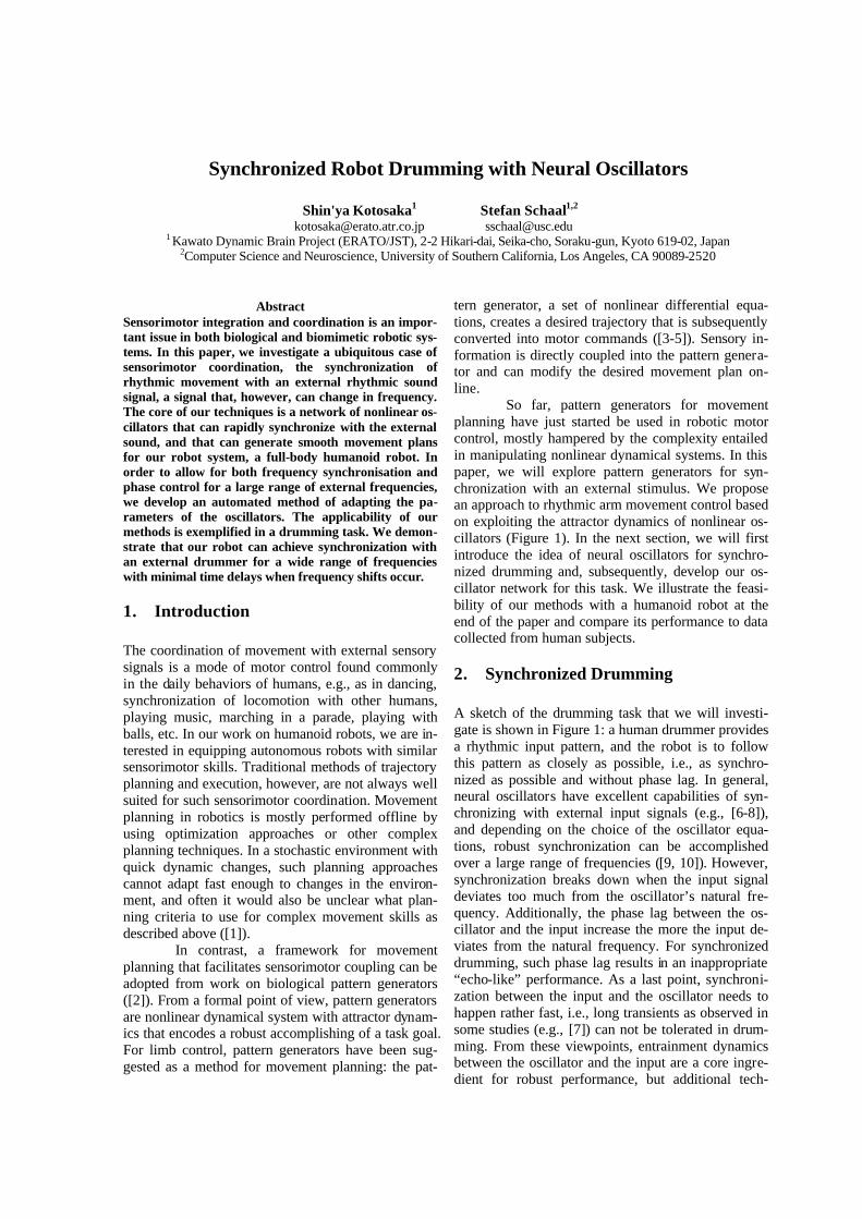
So far, pattern generators for movement planning have just started be used in robotic motor control, mostly hampered by the complexity entailed in manipulating nonlinear dynamical systems. In this paper, we will explore pattern generators for syn-chronization with an external stimulus. We propose an approach to rhythmic arm movement control based on exploiting the attractor dynamics of nonlinear os-cillators (Figure 1). In the next section, we will first introduce the idea of neural oscillators for synchro-nized drumming and, subsequently, develop our os-cillator network for this task. We illustrate the feasi-bility of our methods with a humanoid robot at the end of the paper and compare its performance to data collected from human subjects.
2. Synchronized Drumming A sketch of the drumming task that we will investi-gate is shown in Figure 1: a human drummer provides a rhythmic input pattern, and the robot is to follow this pattern as closely as possible, i.e., as synchro-nized as possible and without phase lag. In general, neural oscillators have excellent capabilities of syn-chronizing with external input signals (e.g., [6-8]), and depending on the choice of the oscillator equa-tions, robust synchronization can be accomplished over a large range of frequencies ([9, 10]). However, synchronization breaks down when the input signal deviates too much from the oscillator’s natural fre-quency. Additionally, the phase lag between the os-cillator and the input increase the more the input de-viates from the natural frequency. For synchronized drumming, such phase lag results in an inappropriate “echo-like” performance. As a last point, synchroni-zation between the input and the oscillator needs to happen rather fast, i.e., long transients as observed in some studies (e.g., [7]) can not be tolerated in drum-ming. From these viewpoints, entrainment dynamics between the oscillator and the input are a core ingre-dient for robust performance, but additional tech-
niques will be required to ensure zero phase lag, minimal transients, and wide frequency range appli-cability. In this paper, we adopted a simple parameter tuning method in an oscillator model to achieve these goals.
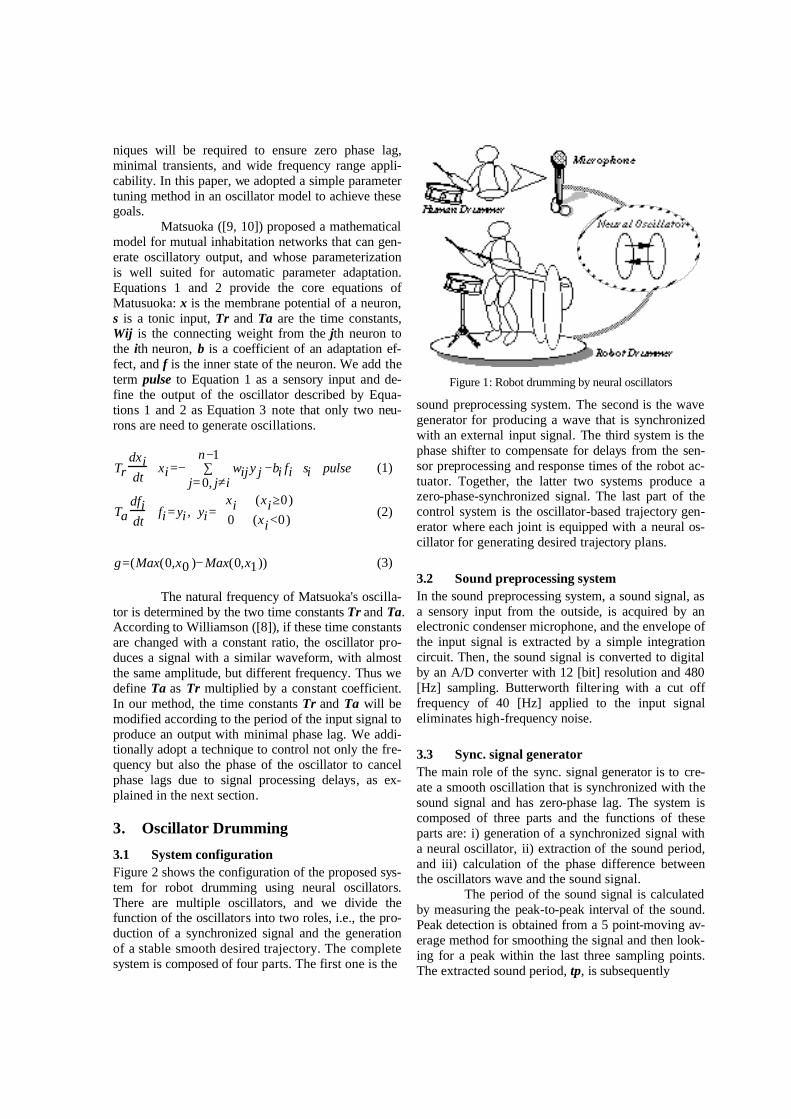
Matsuoka ([9, 10]) proposed a mathematical model for mutual inhabitation networks that can gen-erate oscillatory output, and whose parameterization is well suited for automatic parameter adaptation. Equations 1 and 2 provide the core equations of Matusuoka: x is the membrane potential of a neuron, s is a tonic input, Tr and Ta are the time constants, Wij is the connecting weight from the jth neuron to the ith neuron, b is a coefficient of an adaptation ef-fect, and f is the inner state of the neuron. We add the term pulse to Equation 1 as a sensory input and de-fine the output of the oscillator described by Equa-tions 1 and 2 as Equation 3 note that only two neu-rons are need to generate oscillations.
Trdxidt
+ xi =− wijj= 0, j≠i
n−1∑ y j −bi fi + si + pulse (1)
Tadfidt
+ fi = yi , yi=xi (xi≥0)
0 (xi <0)
(2)
g=(Max(0,x0 )− Max(0,x1)) (3)
The natural frequency of Matsuoka's oscilla-
tor is determined by the two time constants Tr and Ta. According to Williamson ([8]), if these time constants are changed with a constant ratio, the oscillator pro-duces a signal with a similar waveform, with almost the same amplitude, but different frequency. Thus we define Ta as Tr multiplied by a constant coefficient. In our method, the time constants Tr and Ta will be modified according to the period of the input signal to produce an output with minimal phase lag. We addi-tionally adopt a technique to control not only the fre-quency but also the phase of the oscillator to cancel phase lags due to signal processing delays, as ex-plained in the next section.
3. Oscillator Drumming
3.1 System configuration Figure 2 shows the configuration of the proposed sys-tem for robot drumming using neural oscillators. There are multiple oscillators, and we divide the function of the oscillators into two roles, i.e., the pro-duction of a synchronized signal and the generation of a stable smooth desired trajectory. The complete system is composed of four parts. The first one is the
Figure 1: Robot drumming by neural oscillators
sound preprocessing system. The second is the wave generator for producing a wave that is synchronized with an external input signal. The third system is the phase shifter to compensate for delays from the sen-sor preprocessing and response times of the robot ac-tuator. Together, the latter two systems produce a zero-phase-synchronized signal. The last part of the control system is the oscillator-based trajectory gen-erator where each joint is equipped with a neural os-cillator for generating desired trajectory plans.
3.2 Sound preprocessing system In the sound preprocessing system, a sound signal, as a sensory input from the outside, is acquired by an electronic condenser microphone, and the envelope of the input signal is extracted by a simple integration circuit. Then, the sound signal is converted to digital by an A/D converter with 12 [bit] resolution and 480 [Hz] sampling. Butterworth filtering with a cut off frequency of 40 [Hz] applied to the input signal eliminates high-frequency noise.
3.3 Sync. signal generator The main role of the sync. signal generator is to cre-ate a smooth oscillation that is synchronized with the sound signal and has zero-phase lag. The system is composed of three parts and the functions of these parts are: i) generation of a synchronized signal with a neural oscillator, ii) extraction of the sound period, and iii) calculation of the phase difference between the oscillators wave and the sound signal.
The period of the sound signal is calculated by measuring the peak-to-peak interval of the sound. Peak detection is obtained from a 5 point-moving av-erage method for smoothing the signal and then look-ing for a peak within the last three sampling points. The extracted sound period, tp, is subsequently
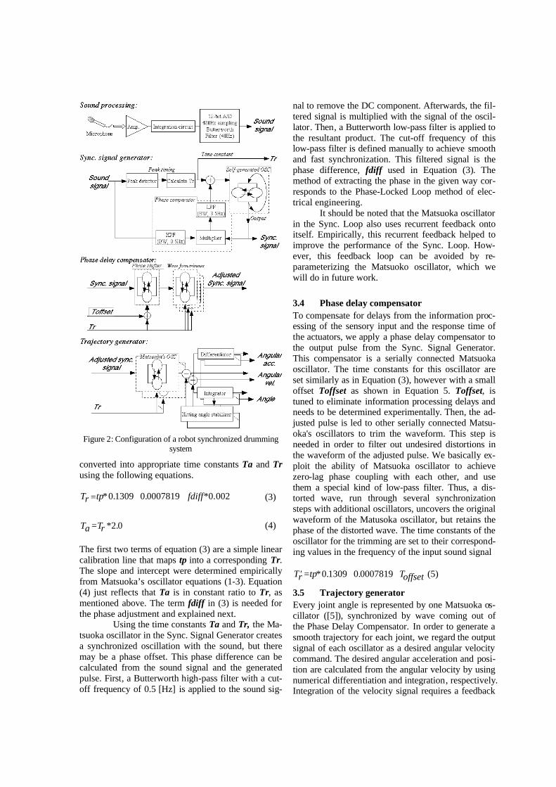
Figure 2: Configuration of a robot synchronized drumming system
converted into appropriate time constants Ta and Tr using the following equations. Tr =tp*0.1309+0.0007819+ fdiff*0.002 (3) Ta =Tr *2.0 (4) The first two terms of equation (3) are a simple linear calibration line that maps tp into a corresponding Tr. The slope and intercept were determined empirically from Matsuoka’s oscillator equations (1-3). Equation (4) just reflects that Ta is in constant ratio to Tr, as mentioned above. The term fdiff in (3) is needed for the phase adjustment and explained next.
Using the time constants Ta and Tr, the Ma-tsuoka oscillator in the Sync. Signal Generator creates a synchronized oscillation with the sound, but there may be a phase offset. This phase difference can be calculated from the sound signal and the generated pulse. First, a Butterworth high-pass filter with a cut-off frequency of 0.5 [Hz] is applied to the sound sig-
nal to remove the DC component. Afterwards, the fil-tered signal is multiplied with the signal of the oscil-lator. Then, a Butterworth low-pass filter is applied to the resultant product. The cut-off frequency of this low-pass filter is defined manually to achieve smooth and fast synchronization. This filtered signal is the phase difference, fdiff used in Equation (3). The method of extracting the phase in the given way cor-responds to the Phase-Locked Loop method of elec-trical engineering.
It should be noted that the Matsuoka oscillator in the Sync. Loop also uses recurrent feedback onto itself. Empirically, this recurrent feedback helped to improve the performance of the Sync. Loop. How-ever, this feedback loop can be avoided by re-parameterizing the Matsuoko oscillator, which we will do in future work.
3.4 Phase delay compensator To compensate for delays from the information proc-essing of the sensory input and the response time of the actuators, we apply a phase delay compensator to the output pulse from the Sync. Signal Generator. This compensator is a serially connected Matsuoka oscillator. The time constants for this oscillator are set similarly as in Equation (3), however with a small offset Toffset as shown in Equation 5. Toffset, is tuned to eliminate information processing delays and needs to be determined experimentally. Then, the ad-justed pulse is led to other serially connected Matsu-oka's oscillators to trim the waveform. This step is needed in order to filter out undesired distortions in the waveform of the adjusted pulse. We basically ex-ploit the ability of Matsuoka oscillator to achieve zero-lag phase coupling with each other, and use them a special kind of low-pass filter. Thus, a dis-torted wave, run through several synchronization steps with additional oscillators, uncovers the original waveform of the Matusoka oscillator, but retains the phase of the distorted wave. The time constants of the oscillator for the trimming are set to their correspond-ing values in the frequency of the input sound signal
′ T r =tp*0.1309+0.0007819+Toffset (5)
3.5 Trajectory generator Every joint angle is represented by one Matsuoka os-cillator ([5]), synchronized by wave coming out of the Phase Delay Compensator. In order to generate a smooth trajectory for each joint, we regard the output signal of each oscillator as a desired angular velocity command. The desired angular acceleration and posi-tion are calculated from the angular velocity by using numerical differentiation and integration, respectively. Integration of the velocity signal requires a feedback
term to obtain stability of the angular position. Equa-tions (6-9) demonstrate how this stability can be achieved. We add a feedback term, d, to the oscilla-tor's output in (6). The term d is calculated by Equa-tion 8 at every moment of impact between drumstick and drum. Pbottom is the deviation between the de-sired joint angle at impact (i.e., at the maximal posi-tion of the oscillatory wave) and the angle achieved at each impact time Pgain and Igain are constants to adjust the feedback effect.
The output of the trajectory generator is fi-nally transformed into a motor command that actuates the robot's joints. Since the magnitude of the output signal of the trajectory generator is not related to any physical quantity, it needs to be multiplied by a coef-ficient Amp to be scaled to an appropriate desired an-gular velocity as shown in Equation (6). The joint an-gle is calculated by numerical integration and then added a constant value, pose, as Equation (7) shows to maintain a suitable drumming posture.
V =Amp*(Max(0,x0)−Max(0,x1))− d (6)
P= Vdt∫ + pose (7) d= Pgain*Pbottom +Igain*c (8)
c=c+ Pbottom (9)
4. Experiments
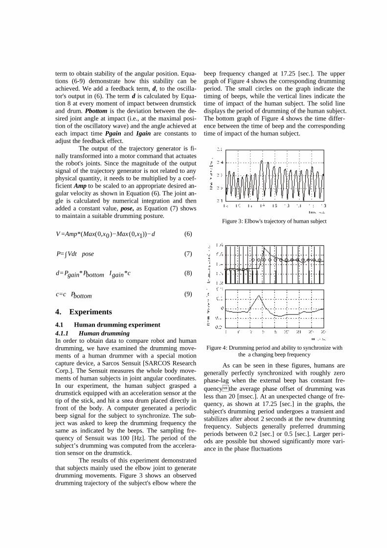
4.1 Human drumming experiment 4.1.1 Human drumming In order to obtain data to compare robot and human drumming, we have examined the drumming move-ments of a human drummer with a special motion capture device, a Sarcos Sensuit [SARCOS Research Corp.]. The Sensuit measures the whole body move-ments of human subjects in joint angular coordinates. In our experiment, the human subject grasped a drumstick equipped with an acceleration sensor at the tip of the stick, and hit a snea drum placed directly in front of the body. A computer generated a periodic beep signal for the subject to synchronize. The sub-ject was asked to keep the drumming frequency the same as indicated by the beeps. The sampling fre-quency of Sensuit was 100 [Hz]. The period of the subject’s drumming was computed from the accelera-tion sensor on the drumstick.
The results of this experiment demonstrated that subjects mainly used the elbow joint to generate drumming movements. Figure 3 shows an observed drumming trajectory of the subject's elbow where the
beep frequency changed at 17.25 [sec.]. The upper graph of Figure 4 shows the corresponding drumming period. The small circles on the graph indicate the timing of beeps, while the vertical lines indicate the time of impact of the human subject. The solid line displays the period of drumming of the human subject. The bottom graph of Figure 4 shows the time differ-ence between the time of beep and the corresponding time of impact of the human subject.
Figure 3: Elbow's trajectory of human subject
Figure 4: Drumming period and ability to synchronize with
the a changing beep frequency
As can be seen in these figures, humans are generally perfectly synchronized with roughly zero phase-lag when the external beep has constant fre-quency�the average phase offset of drumming was less than 20 [msec.]. At an unexpected change of fre-quency, as shown at 17.25 [sec.] in the graphs, the subject's drumming period undergoes a transient and stabilizes after about 2 seconds at the new drumming frequency. Subjects generally preferred drumming periods between 0.2 [sec.] or 0.5 [sec.]. Larger peri-ods are possible but showed significantly more vari-ance in the phase fluctuations
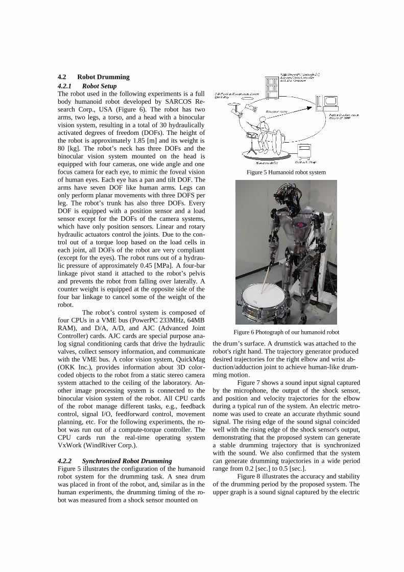
4.2 Robot Drumming 4.2.1 Robot Setup The robot used in the following experiments is a full body humanoid robot developed by SARCOS Re-search Corp., USA (Figure 6). The robot has two arms, two legs, a torso, and a head with a binocular vision system, resulting in a total of 30 hydraulically activated degrees of freedom (DOFs). The height of the robot is approximately 1.85 [m] and its weight is 80 [kg]. The robot’s neck has three DOFs and the binocular vision system mounted on the head is equipped with four cameras, one wide angle and one focus camera for each eye, to mimic the foveal vision of human eyes. Each eye has a pan and tilt DOF. The arms have seven DOF like human arms. Legs can only perform planar movements with three DOFS per leg. The robot’s trunk has also three DOFs. Every DOF is equipped with a position sensor and a load sensor except for the DOFs of the camera systems, which have only position sensors. Linear and rotary hydraulic actuators control the joints. Due to the con-trol out of a torque loop based on the load cells in each joint, all DOFs of the robot are very compliant (except for the eyes). The robot runs out of a hydrau-lic pressure of approximately 0.45 [MPa]. A four-bar linkage pivot stand it attached to the robot’s pelvis and prevents the robot from falling over laterally. A counter weight is equipped at the opposite side of the four bar linkage to cancel some of the weight of the robot.
The robot’s control system is composed of four CPUs in a VME bus (PowerPC 233MHz, 64MB RAM), and D/A, A/D, and AJC (Advanced Joint Controller) cards. AJC cards are special purpose ana-log signal conditioning cards that drive the hydraulic valves, collect sensory information, and communicate with the VME bus. A color vision system, QuickMag (OKK Inc.), provides information about 3D color-coded objects to the robot from a static stereo camera system attached to the ceiling of the laboratory. An-other image processing system is connected to the binocular vision system of the robot. All CPU cards of the robot manage different tasks, e.g., feedback control, signal I/O, feedforward control, movement planning, etc. For the following experiments, the ro-bot was run out of a compute-torque controller. The CPU cards run the real-time operating system VxWork (WindRiver Corp.). 4.2.2 Synchronized Robot Drumming Figure 5 illustrates the configuration of the humanoid robot system for the drumming task. A snea drum was placed in front of the robot, and, similar as in the human experiments, the drumming timing of the ro-bot was measured from a shock sensor mounted on
Figure 5 Humanoid robot system
Figure 6 Photograph of our humanoid robot
the drum’s surface. A drumstick was attached to the robot's right hand. The trajectory generator produced desired trajectories for the right elbow and wrist ab-duction/adduction joint to achieve human-like drum-ming motion.
Figure 7 shows a sound input signal captured by the microphone, the output of the shock sensor, and position and velocity trajectories for the elbow during a typical run of the system. An electric metro-nome was used to create an accurate rhythmic sound signal. The rising edge of the sound signal coincided well with the rising edge of the shock sensor's output, demonstrating that the proposed system can generate a stable drumming trajectory that is synchronized with the sound. We also confirmed that the system can generate drumming trajectories in a wide period range from 0.2 [sec.] to 0.5 [sec.].
Figure 8 illustrates the accuracy and stability of the drumming period by the proposed system. The upper graph is a sound signal captured by the electric
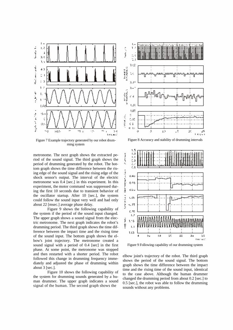
Figure 7 Example trajectory generated by our robot drum-
ming system
metronome. The next graph shows the extracted pe-riod of the sound signal. The third graph shows the period of drumming generated by the robot. The bot-tom graph shows the time difference between the ris-ing edge of the sound signal and the rising edge of the shock sensor's output. The interval of the electric metronome was 0.4 [sec.] in this experiment. In this experiment, the motor command was suppressed dur-ing the first 10 seconds due to transient behavior of the oscillator startup. After 10 [sec.], the system could follow the sound input very well and had only about 22 [msec.] average phase delay.
Figure 9 shows the following capability of the system if the period of the sound input changed. The upper graph shows a sound signal from the elec-tric metronome. The next graph indicates the robot’s drumming period. The third graph shows the time dif-ference between the impact time and the rising time of the sound input. The bottom graph shows the el-bow's joint trajectory. The metronome created a sound signal with a period of 0.4 [sec] in the first phase. At some point, the metronome was stopped and then restarted with a shorter period. The robot followed this change in drumming frequency imme-diately and adjusted the phase of drumming within about 3 [sec.].
Figure 10 shows the following capability of the system for drumming sounds generated by a hu-man drummer. The upper graph indicates a sound signal of the human. The second graph shows the
Figure 8 Accuracy and stability of drumming intervals
Figure 9 Following capability of our drumming system
elbow joint's trajectory of the robot. The third graph shows the period of the sound signal. The bottom graph shows the time difference between the impact time and the rising time of the sound input, identical to the case above. Although the human drummer changed the drumming period from about 0.2 [sec.] to 0.5 [sec.], the robot was able to follow the drumming sounds without any problems.
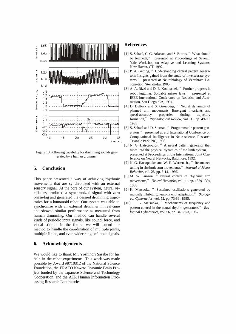
Figure 10 Following capability for drumming sounds gen-erated by a human drummer
5. Conclusion This paper presented a way of achieving rhythmic movements that are synchronized with an external sensory signal. At the core of our system, neural os-cillators produced a synchronized signal with zero phase-lag and generated the desired drumming trajec-tories for a humanoid robot. Our system was able to synchronize with an external drummer in real-time and showed similar performance as measured from human drumming. Our method can handle several kinds of periodic input signals, like sound, force, and visual stimuli. In the future, we will extend our method to handle the coordination of multiple joints, multiple limbs, and even wider range of input signals.
6. Acknowledgements We would like to thank Mr. Yoshinori Sasabe for his help in the robot experiments. This work was made possible by Award #9710312 of the National Science Foundation, the ERATO Kawato Dynamic Brain Pro-ject funded by the Japanese Science and Technology Cooperation, and the ATR Human Information Proc-essing Research Laboratories.
References [1] S. Schaal, C. G. Atkeson, and S. Botros, “What should
be learned?,” presented at Proceedings of Seventh Yale Workshop on Adaptive and Learning Systems, New Haven, CT, 1992.
[2] P. A. Getting, “Understanding central pattern genera-tors: Insights gained from the study of invertebrate sys-tems,” presented at Neurobiology of Vertebrate Lo-comotion, Stockholm, 1985.
[3] A. A. Rizzi and D. E. Koditschek, “Further progress in robot juggling: Solvable mirror laws,” presented at IEEE International Conference on Robotics and Auto-mation, San Diego, CA, 1994.
[4] D. Bullock and S. Grossberg, “Neural dynamics of planned arm movements: Emergent invariants and speed-accuracy properties during trajectory formation,” Psychological Review, vol. 95, pp. 49-90, 1988.
[5] S. Schaal and D. Sternad, “Programmable pattern gen-erators,” presented at 3rd International Conference on Computational Intelligence in Neuroscience, Research Triangle Park, NC, 1998.
[6] N. G. Hatsopoulos, “A neural pattern generator that tunes into the physical dynamics of the limb system,” presented at Proceedings of the International Joint Con-ference on Neural Networks, Baltimore, 1992.
[7] N. G. Hatsopoulos and W. H. Warren, Jr., “Resonance tuning in rhythmic arm movements,” Journal of Motor Behavior, vol. 28, pp. 3-14, 1996.
[8] M. Williamson, “ Neural control of rhythmic arm movements,” Neural Networks, vol. 11, pp. 1379-1394, 1998.
[9] K. Matsuoka, “Sustained oscillations generated by mutually inhibiting neurons with adaptation,” Biologi-cal Cybernetics, vol. 52, pp. 73-83, 1985.
[10] K. Matsuoka, “Mechanisms of frequency and pattern control in the neural rhythm generators,” Bio-logical Cybernetics, vol. 56, pp. 345-353, 1987.