Sync DIN Rail Power Supply 24V 100W Series / DRS … · TECHNICAL DATASHEET Sync DIN Rail Power...
15
TECHNICAL DATASHEET Sync DIN Rail Power Supply 24V 100W Series / DRS-24V100W1A□ / DRS-24V100W1N□ All parameters are specified at 25°C ambient and AC input unless otherwise indicated. www.DeltaPSU.com (March 2016, Rev. 00) 1 Highlights & Features – Ultra-compact size and galvanic isolation up to 3.0KVac between input to output and input to ground – Universal AC input voltage and full power from -10°C to +55°C operation – Up to 89.0% efficiency and built-in active PFC – Low earth leakage current < 0.5mA @ 264Vac – Built-in DC OK relay contact option available – Extreme low temperature cold start at -40°C – NEC Class 2 / Limited Power Source (LPS) certified (DRS-24V100W1N☐) Safety Standards CB Certified for worldwide use Model Number: DRS-24V100W1☐☐ Unit Weight: 0.325 kg (0.72 lb) Dimensions (L x W x D): 75 x 45 x 100 mm (2.95 x 1.77 x 3.94 inch) General Description The ultra-compact and competitively priced Delta Sync DIN Rail DRS-24V100W1 ☐☐ power supply is designed for industrial applications requiring highly reliable power supply that must fit in a small space. The Sync series operates with universal AC input range and offers full power up to 55°C. The output is adjustable from 24-28 volts for DRS-24V100W1A☐ and 22-24 volts for DRS- 24V100W1N☐, and can support up to 3000 microfarads of load capacitance. A green LED indicates output is present. The design is certified according to IEC/EN/UL 60950-1 Information Technology Equipment (ITE) and UL 508 Industrial Control Equipment (ICE). The series is also fully compliant with RoHS Directive 2011/65/EU for environmental protection. NEC Class 2 and Limited Power Source (LPS) approvals are available for DRS-24V100W1N☐. Model Information Sync DIN Rail Power Supply Model Number Input Voltage Range Rated Output V oltage Rated Output Current DRS-24V100W1A☐ 85-264Vac (120-375Vdc) 24Vdc 4.0A DRS-24V100W1N☐ 3.8A Model Numbering DR S – 24V 100W 1 N □ DIN Rail Product Series S – Sync Series Output Voltage 100W series Single Phase A – Non NEC Class 2 N – NEC Class 2 Z – Without DC OK Relay Contact R – With DC OK Relay Contact *This picture is for reference to DRS-24V100W series only.
Transcript of Sync DIN Rail Power Supply 24V 100W Series / DRS … · TECHNICAL DATASHEET Sync DIN Rail Power...

TECHNICAL DATASHEET
Sync DIN Rail Power Supply 24V 100W Series / DRS-24V100W1A□ / DRS-24V100W1N□
All parameters are specified at 25°C ambient and AC input unless otherwise indicated. www.DeltaPSU.com (March 2016, Rev. 00)
1
Highlights & Features – Ultra-compact size and galvanic isolation up to 3.0KVac
between input to output and input to ground – Universal AC input voltage and full power from -10°C to
+55°C operation – Up to 89.0% efficiency and built-in active PFC – Low earth leakage current < 0.5mA @ 264Vac – Built-in DC OK relay contact option available – Extreme low temperature cold start at -40°C – NEC Class 2 / Limited Power Source (LPS) certified
(DRS-24V100W1N☐)
Safety Standards
CB Certified for worldwide use
Model Number: DRS-24V100W1☐☐ Unit Weight: 0.325 kg (0.72 lb) Dimensions (L x W x D): 75 x 45 x 100 mm
(2.95 x 1.77 x 3.94 inch) General Description The ultra-compact and competitively priced Delta Sync DIN Rail DRS-24V100W1☐☐power supply is designed for industrial applications requiring highly reliable power supply that must fit in a small space. The Sync series operates with universal AC input range and offers full power up to 55°C. The output is adjustable from 24-28 volts for DRS-24V100W1A☐ and 22-24 volts for DRS-24V100W1N☐, and can support up to 3000 microfarads of load capacitance. A green LED indicates output is present. The design is certified according to IEC/EN/UL 60950-1 Information Technology Equipment (ITE) and UL 508 Industrial Control Equipment (ICE). The series is also fully compliant with RoHS Directive 2011/65/EU for environmental protection. NEC Class 2 and Limited Power Source (LPS) approvals are available for DRS-24V100W1N☐. Model Information
Sync DIN Rail Power Supply Model Number Input Voltage Range Rated Output Voltage Rated Output Current DRS-24V100W1A☐ 85-264Vac (120-375Vdc) 24Vdc 4.0A DRS-24V100W1N☐ 3.8A
Model Numbering
DR S – 24V 100W 1 N □ DIN Rail Product Series
S – Sync Series Output Voltage 100W series Single Phase A – Non NEC
Class 2 N – NEC Class 2
Z – Without DC OK Relay Contact R – With DC OK Relay Contact
*This picture is for reference to DRS-24V100W series only.

TECHNICAL DATASHEET
Sync DIN Rail Power Supply 24V 100W Series / DRS-24V100W1A□ / DRS-24V100W1N□
All parameters are specified at 25°C ambient and AC input unless otherwise indicated. www.DeltaPSU.com (March 2016, Rev. 00)
2
Specifications
Model Number DRS-24V100W1A☐ DRS-24V100W1N☐
Input Ratings / Characteristics
Nominal Input Voltage 100-240Vac Input Voltage Range 85-264Vac Nominal Input Frequency 50-60Hz Input Frequency Range 47-63Hz DC Input Voltage Range* 120-375Vdc Input Current < 1.2A @ 115Vac, < 0.6A @ 230Vac Efficiency at 100% Load > 89% @ 115Vac & 230Vac Max Power Dissipation 0% load
100% load < 0.4W @ 115Vac & 230Vac < 11W @ 115Vac & 230Vac
Max Inrush Current (Cold Start) < 25A @ 115Vac, < 40A @ 230Vac Power Factor at 100% Load > 0.97 @ 115Vac, > 0.9 @ 230Vac Leakage Current (Neutral to PE terminal)
< 0.5mA @ 264Vac
*Fulfills test conditions for DC input. Safety approval for DC input can be obtained upon request. Output Ratings / Characteristics**
Nominal Output Voltage 24Vdc Factory Set Point Tolerance 24Vdc ± 2% Output Voltage Adjustment Range 24-28Vdc 22-24Vdc Output Current 4.0A (96W max.) 3.8A (91.2W max.) Output Power 96W 91.2W Line Regulation < 0.5% (@ 85-264Vac, 100% load) Load Regulation < 1.0% (@ 85-264Vac, 0-100% load) PARD*** (20MHz) < 50mVpp @ > 0°C to 70°C
< 100mVpp @ 0°C to -20°C
Rise Time < 100ms @ nominal input (100% load) Start-up Time < 2,500ms @ 115Vac (100% load)
< 1,500ms @ 230Vac (100% load)
Hold-up Time > 50ms @ 115Vac & 230Vac (100% load) Dynamic Response (Overshoot & Undershoot O/P Voltage) ± 5% @ 85-264Vac input, 0-100% load
(Slew Rate: 0.1A/μs, 50% duty cycle @ 5Hz to 1KHz)
Start-up with Capacitive Loads 3,000µF Max Functional DC OK Relay Contact
(for DRS-24V100W1AR, DRS-24V100W1NR)
30V / 1A, resistive load The relay contact are normally “ON” (closed) when the output (Vout) is greater than 75% of its rated value and “OFF” (opened) when the output (Vout) is less than 75% typ.
**For power de-rating from < -10°C to -20°C, and 55°C to 70°C, see power de-rating on page 3. ***PARD is measured with an AC coupling mode, 5cm wires, and in parallel with 0.1μF ceramic capacitor & 47μF electrolytic capacitor.

TECHNICAL DATASHEET
Sync DIN Rail Power Supply 24V 100W Series / DRS-24V100W1A□ / DRS-24V100W1N□
All parameters are specified at 25°C ambient and AC input unless otherwise indicated. www.DeltaPSU.com (March 2016, Rev. 00)
3
Model Number DRS-24V100W1A☐ DRS-24V100W1N☐
Mechanical
Case Cover / Chassis Plastic Dimensions (L x W x D) 75 x 45 x 100 mm (2.95 x 1.77 x 3.94 inch)
Unit Weight 0.325 kg (0.72 lb) Indicator Green LED (DC OK) Cooling System Convection Terminal Input 3 Pins (Rated 300V/16A) Output DRS-24V100W1☐Z: 4 Pins (Rated 300V/16A)
DRS-24V100W1☐R: 6 Pins (Rated 300V/16A) Wire Input / Output AWG 22-12 / AWG 20-12 Mounting Rail Standard TS35 DIN Rail in accordance with EN 60715 Noise (1 Meter from power supply) Sound Pressure Level (SPL) < 25dBA
Environment
Surrounding Air Temperature Operating -20°C to +70°C (Cold start at -40°C @ 40% load) Storage -40°C to +85°C
Power De-rating -10°C to -20°C de-rate power by 2% / °C > 55°C de-rate power by 3.33% / °C
Operating Humidity 5 to 95% RH (Non-Condensing) Operating Altitude 0 to 2,000 Meters (6,560 ft.) Shock Test Non-Operating IEC60068-2-27, Half Sine Wave: 50G for a duration of 11ms;
3 times per direction, 9 times in total
Operating IEC 60068-2-27, Half Sine Wave: 10G for a duration of 11ms; 1 time in X axis
Vibration Non-Operating IEC 60068-2-6, Random: 5-500Hz; 2.09Grms, 20 min per axis for all X, Y, Z directions
Operating IEC 60068-2-6, Sine Wave: 10-500Hz; 2G peak; displacement of 0.35mm; 1 octave per min; 60 min per axis for all X, Y, Z directions
Pollution Degree 2 Protections
Overvoltage < 34.8V, SELV Output, Latch Mode Overload / Overcurrent 105~140% of rated load current,
Fold Forward Mode (current rises, voltage drops), Auto-recovery when the fault is removed
Over Temperature < 75°C Surrounding Air Temperature @ 100% load, Latch Mode
Short Circuit Hiccup Mode, Non-Latching (Auto-recovery when the fault is removed)
Internal Fuse T3.15A Degree of Protection IP20 Protection Against Shock Class I with PE* connection
*PE: Primary Earth

TECHNICAL DATASHEET
Sync DIN Rail Power Supply 24V 100W Series / DRS-24V100W1A□ / DRS-24V100W1N□
All parameters are specified at 25°C ambient and AC input unless otherwise indicated. www.DeltaPSU.com (March 2016, Rev. 00)
4
Model Number DRS-24V100W1A☐ DRS-24V100W1N☐
Reliability Data
MTBF Telcordia SR-332 > 700,000 hrs, I/P: 115Vac & 230Vac, O/P: 100% load, Ta: 25°C
MIL-HDBK-217F 121,000 hrs, I/P: 115Vac & 230Vac, O/P: 100% load, Ta: 25°C
Expected Cap Life Time 10 years (115ac & 230Vac, 50% load @ 40°C) Safety Standards / Directives
Safety Entry Low Voltage SELV (EN 60950) Electrical Safety TUV Bauart
UL/cUL recognized CB Scheme
EN 60950-1 UL 60950-1, CSA C22.2 No. 60950-1 (File No. E191395) IEC 60950-1, Limited Power Source (LPS, for DRS-24V100WN☐ only)
Industrial Control Equipment UL/cUL listed UL 508 and CSA C22.2 No. 107.1-01 (File No. E315335) Class 2 Power Supply UL/cUL recognized UL 60950-1, CSA C22.2 No. 60950-1(File No. E191395)
(for DRS-24V100WN☐ only) CE In conformance with EMC Directive 2004/108/EC and Low
Voltage Directive 2006/95/EC
Material and Parts RoHS Directive 2011/65/EU Compliant Galvanic Isolation Input to Output 3.0KVac Input to Ground 3.0KVac Output to Ground 0.5KVac

TECHNICAL DATASHEET
Sync DIN Rail Power Supply 24V 100W Series / DRS-24V100W1A□ / DRS-24V100W1N□
All parameters are specified at 25°C ambient and AC input unless otherwise indicated. www.DeltaPSU.com (March 2016, Rev. 00)
5
Model Number DRS-24V100W1A☐ DRS-24V100W1N☐
EMC
EMC / Emissions Generic Standards: EN 61000-6-3, EN 61000-6-4 CISPR 22, EN 55022 EN 55011, FCC Title 47: Class B
Component Power Supply for General Use EN 61204-3 Immunity to Generic Standards: EN 55024, EN 61000-6-1, EN 61000-6-2
Electrostatic Discharge IEC 61000-4-2 Level 3 Criteria A1) Air Discharge: 8kV Contact Discharge: 6kV
Radiated Field IEC 61000-4-3 Level 3 Criteria A1) 80MHz-1GHz, 10V/M with 1kHz tone / 80% modulation 1.4GHz-2GHz, 3V/M with 1kHz tone / 80% modulation 2GHz-2.7GHz, 1V/M with 1kHz tone / 80% modulation
Electrical Fast Transient / Burst IEC 61000-4-4 Level 3 Criteria A1) 2kV
Surge IEC 61000-4-5 Level 3 Criteria A1) Common Mode3): 2kV Differential Mode4): 1kV
Conducted IEC 61000-4-6 Level 3 Criteria A1) 150kHz-80MHz, 10Vrms
Power Frequency Magnetic Fields IEC 61000-4-8 Criteria A1) 30A/Meter
Voltage Dips and Interruptions IEC 61000-4-11 0% of 100Vac, 20ms 0% of 100Vac, 5000ms 40% of 100Vac, 200ms 70% of 100Vac, 10ms 70% of 100Vac, 500ms 0% of 240Vac, 20ms 0% of 240Vac, 5000ms 40% of 240Vac, 200ms 70% of 240Vac, 500ms
Criteria A1) Criteria B2) Criteria B2) Criteria A1) Criteria A1) Criteria A1) Criteria B2) Criteria A1) Criteria A1)
Low Energy Pulse Test (Ring Wave) IEC 61000-4-12 Level 3 Criteria A1) Common Mode3): 2kV Differential Mode4): 1kV
Harmonic Current Emission IEC/EN 61000-3-2, Class A Voltage Fluctuation and Flicker IEC/EN 61000-3-3
1) Criteria A: Normal performance within the specification limits 2) Criteria B: Temporary degradation or loss of function which is self-recoverable 3) Asymmetrical: Common mode (Line to earth) 4) Symmetrical: Differential mode (Line to line)

TECHNICAL DATASHEET
Sync DIN Rail Power Supply 24V 100W Series / DRS-24V100W1A□ / DRS-24V100W1N□
All parameters are specified at 25°C ambient and AC input unless otherwise indicated. www.DeltaPSU.com (March 2016, Rev. 00)
6
Block Diagram DRS-24V100W1☐Z
DRS-24V100W1☐R
TECHNICAL DATASHEET
Sync DIN Rail Power Supply 24V 100W Series / DRS-24V100W1A□ / DRS-24V100W1N□
All parameters are specified at 25°C ambient and AC input unless otherwise indicated. www.DeltaPSU.com (March 2016, Rev. 00)
7
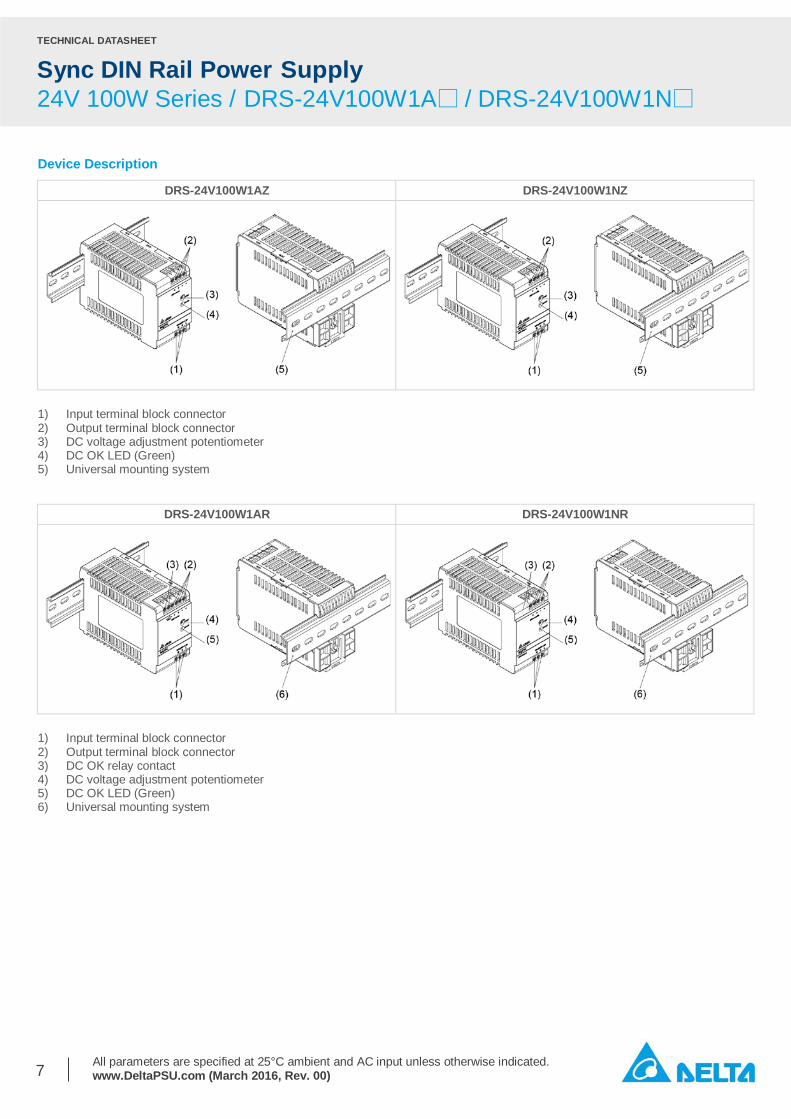
Device Description
DRS-24V100W1AZ DRS-24V100W1NZ
1) Input terminal block connector 2) Output terminal block connector 3) DC voltage adjustment potentiometer 4) DC OK LED (Green) 5) Universal mounting system
DRS-24V100W1AR DRS-24V100W1NR
1) Input terminal block connector 2) Output terminal block connector 3) DC OK relay contact 4) DC voltage adjustment potentiometer 5) DC OK LED (Green) 6) Universal mounting system
TECHNICAL DATASHEET
Sync DIN Rail Power Supply 24V 100W Series / DRS-24V100W1A□ / DRS-24V100W1N□
All parameters are specified at 25°C ambient and AC input unless otherwise indicated. www.DeltaPSU.com (March 2016, Rev. 00)
8
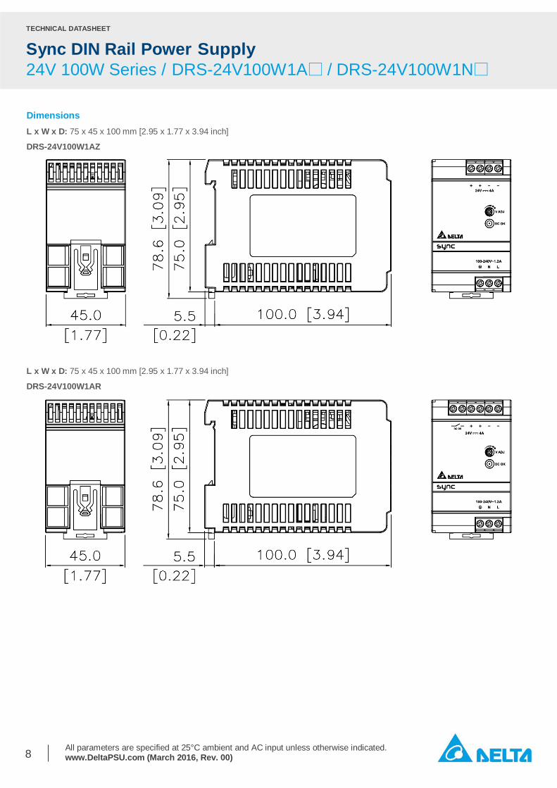
Dimensions L x W x D: 75 x 45 x 100 mm [2.95 x 1.77 x 3.94 inch]
DRS-24V100W1AZ
L x W x D: 75 x 45 x 100 mm [2.95 x 1.77 x 3.94 inch]
DRS-24V100W1AR

TECHNICAL DATASHEET
Sync DIN Rail Power Supply 24V 100W Series / DRS-24V100W1A□ / DRS-24V100W1N□
All parameters are specified at 25°C ambient and AC input unless otherwise indicated. www.DeltaPSU.com (March 2016, Rev. 00)
9
L x W x D: 75 x 45 x 100 mm [2.95 x 1.77 x 3.94 inch]
DRS-24V100W1NZ
L x W x D: 75 x 45 x 100 mm [2.95 x 1.77 x 3.94 inch]
DRS-24V100W1NR
TECHNICAL DATASHEET
Sync DIN Rail Power Supply 24V 100W Series / DRS-24V100W1A□ / DRS-24V100W1N□
All parameters are specified at 25°C ambient and AC input unless otherwise indicated. www.DeltaPSU.com (March 2016, Rev. 00)
10
Engineering Data
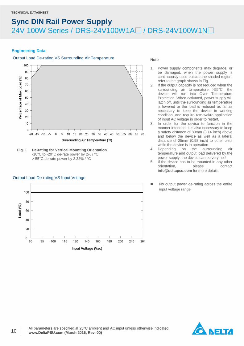
Output Load De-rating VS Surrounding Air Temperature
Output Load De-rating VS Input Voltage
Note 1. Power supply components may degrade, or
be damaged, when the power supply is continuously used outside the shaded region, refer to the graph shown in Fig. 1.
2. If the output capacity is not reduced when the surrounding air temperature >55°C, the device will run into Over Temperature Protection. When activated, power supply will latch off, until the surrounding air temperature is lowered or the load is reduced as far as necessary to keep the device in working condition, and require removal/re-application of input AC voltage in order to restart.
3. In order for the device to function in the manner intended, it is also necessary to keep a safety distance of 80mm (3.14 inch) above and below the device as well as a lateral distance of 25mm (0.98 inch) to other units while the device is in operation.
4. Depending on the surrounding air temperature and output load delivered by the power supply, the device can be very hot!
5. If the device has to be mounted in any other orientation, please contact [email protected] for more details.
Fig. 1 De-rating for Vertical Mounting Orientation -10°C to -20°C de-rate power by 2% / °C > 55°C de-rate power by 3.33% / °C
No output power de-rating across the entire input voltage range

TECHNICAL DATASHEET
Sync DIN Rail Power Supply 24V 100W Series / DRS-24V100W1A□ / DRS-24V100W1N□
All parameters are specified at 25°C ambient and AC input unless otherwise indicated. www.DeltaPSU.com (March 2016, Rev. 00)
11
Assembly & Installation The power supply unit (PSU) can be mounted on 35mm DIN rails in accordance with EN60715. The device should be installed with input terminal block at the bottom. Each device is delivered ready to install. Mounting
Safety Instructions
Dismounting
Fig. 2.1 Mounting Snap on the DIN rail as shown in Fig. 2.1: 1. Tilt the unit slightly upwards and put it onto the DIN rail. 2. Push downwards until stopped. 3. Press against the bottom front side for locking. 4. Shake the unit slightly to ensure that it is secured.
– ALWAYS switch mains of input power OFF before connecting and disconnecting the input voltage to the device. If mains are not turned OFF, there is risk of explosion / severe damage.
– To guarantee sufficient convection cooling, keep a distance of 80mm (3.14 inch) above and below the device as well as a lateral distance of 25mm (0.98 inch) to other units.
– Note that the enclosure of the device can become very hot depending on the surrounding air temperature and output load connected to the device. Risk of burns!
– The main power must be turned off before connecting or disconnecting the wires to the terminals!
– DO NOT insert any objects into the device. – Dangerous voltages present for at least 5 minutes after
disconnecting all sources of power. – The power supplies unit should be installed in minimum
IP54 rated enclosure. – The power supplies are built in units and must be installed
in a cabinet or room (condensation free environment and indoor location) that is relatively free of conductive contaminants.
Fig. 2.2 Dismounting To uninstall, pull or slide down the latch with screw driver as shown in Fig. 2.2. Then slide the power supply unit (PSU) in the opposite direction, release the latch and pull out the power supply unit (PSU) from the rail.
TECHNICAL DATASHEET
Sync DIN Rail Power Supply 24V 100W Series / DRS-24V100W1A□ / DRS-24V100W1N□
All parameters are specified at 25°C ambient and AC input unless otherwise indicated. www.DeltaPSU.com (March 2016, Rev. 00)
12
Functions
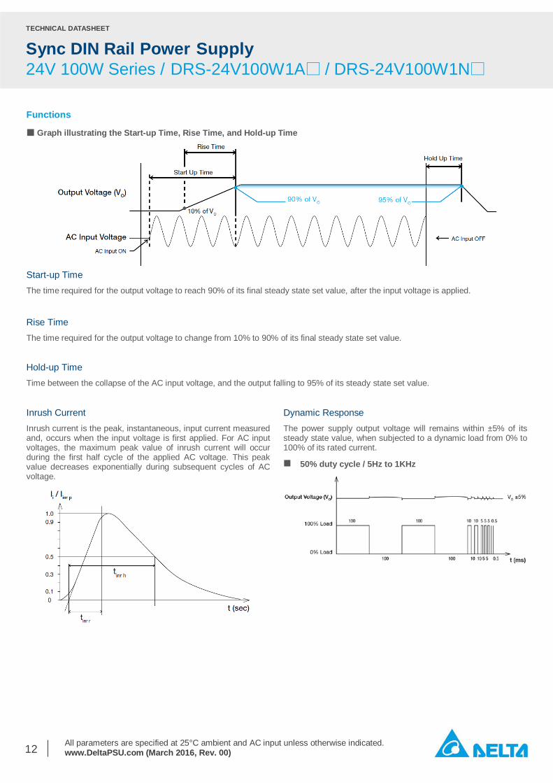
■ Graph illustrating the Start-up Time, Rise Time, and Hold-up Time
Start-up Time The time required for the output voltage to reach 90% of its final steady state set value, after the input voltage is applied. Rise Time The time required for the output voltage to change from 10% to 90% of its final steady state set value. Hold-up Time Time between the collapse of the AC input voltage, and the output falling to 95% of its steady state set value. Inrush Current Inrush current is the peak, instantaneous, input current measured and, occurs when the input voltage is first applied. For AC input voltages, the maximum peak value of inrush current will occur during the first half cycle of the applied AC voltage. This peak value decreases exponentially during subsequent cycles of AC voltage.
Dynamic Response The power supply output voltage will remains within ±5% of its steady state value, when subjected to a dynamic load from 0% to 100% of its rated current.
50% duty cycle / 5Hz to 1KHz

TECHNICAL DATASHEET
Sync DIN Rail Power Supply 24V 100W Series / DRS-24V100W1A□ / DRS-24V100W1N□
All parameters are specified at 25°C ambient and AC input unless otherwise indicated. www.DeltaPSU.com (March 2016, Rev. 00)
13
Overload & Overcurrent Protections (Auto-Recovery) The power supply’s Overcurrent Protection (OCP) will be activated when output current is about 105~140% of IO (Max load). When this occurs, the VO will start to droop (refer to Ⓐ below). Once the output current is about 5.2A typ. (for DRS-24V100W1A☐ ) and 4.2A typ. (for DRS-24V100W1N☐ ) the power supply will start to operate in “Hiccup mode” (Auto-Recovery mode). The power supply will recover once the fault condition of the OCP is removed and output current is back within the specifications.
Short Circuit Protection (Auto-Recovery) The power supply’s output Short Circuit Protection function also provides protection against short circuits. When a short circuit is applied, the output current will operate in “Hiccup mode”. The power supply will return to normal operation after the short circuit is removed.
Overvoltage Protection (Latch Mode) The power supply’s overvoltage circuit will be activated when its internal feedback circuit fails. The output voltage shall not exceed its specifications defined on Page 3 under “Protections”. Power supply will latch off, and require removal/re-application of input AC voltage in order to restart. The power supply should be latch.
Over Temperature Protection (Latch Mode) As described in load de-rating section, the power supply also has Over Temperature Protection (OTP). In the event of a higher operating temperature at 100% load; or, when the operating temperature is beyond what is recommended in the de-rating graph, the OTP circuit will be activated. When activated, power supply will latch off, until the surrounding air temperature drops to its normal operating temperature or the load is reduced as recommended in the de-rating graph. Removal/re-application of input AC voltage will then be required in order to restart.

TECHNICAL DATASHEET
Sync DIN Rail Power Supply 24V 100W Series / DRS-24V100W1A□ / DRS-24V100W1N□
All parameters are specified at 25°C ambient and AC input unless otherwise indicated. www.DeltaPSU.com (March 2016, Rev. 00)
14
Operating Mode Redundant Operation
Step 3. Connect the system load to Vout. Please note that output voltage Vout from DRR module will be = VO (output voltage of power supply) – Vdrop* (in DRR module). *Vdrop will vary from 0.60V to 0.90V (Typical 0.65V) depending on the load current and surrounding air temperature. Parallel Operation
Fig. 3 Redundancy Operation Connection Diagram
Fig. 4 Parallel Operation Connection Diagram
The power supply units (PSUs) can also be used for parallel operation in order to increase the output power. The difference in output voltage between the two units must be kept to within 25mV of each other. This difference must be verified with the same output load connected independently to each unit.
Parameters such as EMI, inrush current, leakage current, PARD, start up time will be different from those on the datasheet, when two units are connected in parallel. The user will need to verify that any differences will still allow the two power supplies connected in parallel will work properly in their product/application.
In order to ensure proper redundant operation for the power supply units (PSUs), the output voltage difference between the two units must be kept at 0.45~0.50V for these 24V supplies. Follow simple steps given below to set them up for the redundant operation: Step 1. Measure output voltage of PSU 1 and PSU 2. If PSU 1 is the master unit, then VO of PSU 1 must be higher than PSU 2. In order to set the output voltage, individually connect each power supply to 50% of rated load at any line voltage from 85-264Vac, and set the PSU 1 and PSU 2 output voltage. Step 2. Connect the power supply units PSU 1 and PSU 2 to Vin 1 & Vin 2, respectively, of the DRR-20N (or 20A) module shown on the right of above diagram.

TECHNICAL DATASHEET
Sync DIN Rail Power Supply 24V 100W Series / DRS-24V100W1A□ / DRS-24V100W1N□
All parameters are specified at 25°C ambient and AC input unless otherwise indicated. www.DeltaPSU.com (March 2016, Rev. 00)
15
Others
Delta RoHS Compliant Restriction of the usage of hazardous substances
The European directive 2011/65/EU limits the maximum impurity level of homogeneous materials such as lead, mercury, cadmium, chrome, polybrominated flame retardants PBB and PBDE for the use in electrical and electronic equipment. RoHS is the abbreviation for “Restriction of the use of certain hazardous substances in electrical and electronic equipment”.
This product conforms to this standard.
PFC – Norm EN 61000-3-2
Line Current Harmonic content
Typically, the input current waveform is not sinusoidal due to the periodical peak charging of the input capacitor. In industrial environment, complying with EN 61000-3-2 is only necessary under special conditions. Complying to this standard can have some technical drawbacks, such as lower efficiency as well as some commercial aspects such as higher purchasing costs. Frequently, the user does not profit from fulfilling this standard, therefore, it is important to know whether it is mandatory to meet this standard for a specific application.