Symmetrical . · PDF fileThe symmetrical cladding facade system with natural stone works well...
9
Symmetrical Cladding. Laying instructions
Transcript of Symmetrical . · PDF fileThe symmetrical cladding facade system with natural stone works well...

Symmetrical Cladding.Laying instructions

2 3
PREFACE
These laying instructions describe the application of
InterSIN® slate, SIN 970 and ColorSIN®, CS 35
or CS 50 together with the aluminium substructure
included with delivery and the corresponding mounting
materials as a complete system. The instructions are the
basis for appropriate planning and application-oriented
technical solutions in usual situations. The detail drawings
found in the laying instructions depict some of the
standard details of the symmetrical cladding.
The following pages contain technical information about
the curtain-type, rearventilated facade and practical
guidelines for construction and implementation.
The symmetrical cladding facade system with
natural stone works well for new buildings as well as for
renovation in terms of aesthetics, design and cost. These
instructions serve as an orientation for the planner and
the implementing firm.
They are based on current, state-of-the-art construction
technology. However, the planner and the implementing
firm must consider the effects of the system application
on the respective structure as well as local and climatic
conditions, and demands related to construction
physics.
Using these laying instructions does not imply an
exemption from individual responsibility. We reserve the
right to make revisions resulting from further develop-
ment of the facade system.
Mayen, December 2007
C O N T E N T S
1. CONSTruCTiON rEquirEmENTS
1.1. Weather protection
1.2. Thermal insulation
1.2.1. Introduction
1.2.2. Insulation
1.2.3. Thermal bridge
1.3. Sound-proofing
1.4. Fire prevention
1.5. Rear ventilation, ventilation (air intake and exhaust)
1.5.1. Rear ventilation
1.5.2. Ventilation
(air intake and exhaust)
2. TEChNiCal NOTES
3. PrOduCT TyPES
3.1. Slate
3.2. Aluminium substructure
4. TEChNiCal dETailS
4.1. Base design
4.2. Parapet connection
4.3. Reveal
4.4. External building corner
4.5. Internal building corner
5. aSSEmbly NOTES
1. CoNSTRuCTIoN REquIREmENTS
1.1. Weather protection
The curtain-type, rear-ventilated facade guarantees long-lasting protection against effects of the weather. The building stays warm in winter and cool in summer, and the climate indoors remains comfortable. The load-bearing external walls and the insulation stay dry and therefore remain fully functional. The circulation of air in the ventilation space quickly dries up any rain that
penetrates through open joints in a downpour.
1.2. Thermal insulation
1.2.1. The structural thermal insulation for energy conservation is governed by the Energy Conservation Ordinance (EnEV) of 2002, an amendment of the fundamental Energy Conservation Law of 1976. Reducing energy consumption and minimizing CO2 emissions are among the most important goals of the Energy Conserva-tion Ordinance (EnEV). In addition to the construction design advantages offered by the curtain-type, rear- ventilated facade, the high quality thermal insulation required by the Energy Conservation Ordinance (EnEV) contributes to environmental protection and pays for itself in a short period of time, due to lower heating
costs.
1.2.2. Insulation
Mineral fibres, water-proofed according to DIN/EN Standard 13162, with thermal conductivity 035 (0.035W/mK) or 040 (0.040W/mK) provide thermal insulation for the curtain-type, rear-ventilated facades. The aluminium substructure of the symmetrical cladding can accommodate insulation of the thickness required by the Energy Conservation Ordinance (EnEV). Install the facade insulation boards between the substrate and the insulation layer in a tightly adjoining arrangement, leaving no space, in conformity with the standards. Affix them mechanically with insulation fasteners - on average 5 fasteners per m². Mount them tightly to the abutting
components.
1.2.3. Thermal bridge
Thermal bridges are locations in the building sheath where there is an increased heat flow. Installing an insulating underlay between the supporting structure and the wall holders (Thermostopp) weakens thermal bridges considerably. Installing the insulation layer properly
reduces the occurrence of thermal bridges.
1.3. Sound-proofing
To prove that a facade design is sound-proof, the entire wall structure and components (windows, etc.) must be defined. Curtain-type, rear-ventilated facades have an extremely positive influence on the sound-insulating
effect of the external wall.
1.4. Fire prevention
The symmetrical cladding with aluminium substructure and the corresponding mounting materials meet the highest requirements for non-combustibility (Building
material class A1, DIN 4102).
1.5. Rear ventilation, ventilation (air intake and exhaust)
1.5.1. Rear ventilation
Rear ventilation is essential for reducing moisture, for draining any rain that may penetrate during a downpour, for capillary separation of the facade cladding from the insulation layer, and for draining water that condenses on the internal surface of the facade cladding. The cross-section to be kept clear for ventilation between the facade cladding and the layer behind it must measure at least 20 mm. Construction tolerances and possible inclined alignment of the building must be taken into account. This space for rear ventilation may be decreased to 5 mm in some places, e.g. due to the
substructure or wall unevenness.
1.5.2. Ventilation openings (air intake and exhaust)
The space for rear ventilation requires openings for air intake and exhaust. These openings are designed such that their operational reliability is guaranteed over the entire lifetime of the building. They may not be damaged by contaminants or other external influences. The openings are located at the lowest and highest point of the facade cladding, in the windowsill/lintel area and where there are penetrations. In order for the rear ventilation to function, air intake and exhaust openings of at least 50 cm² per m of wall length must be present. Constrictions in the cross-section must be taken into consideration (e.g. air inlet grill).
4 5
2. TEChNICAl NoTES
The most current versions of these fundamental rules
must be followed in principle:
u Relevant local building regulations in each case
u Rules for cladding external walls with slate (Central
Association of German Roofers)
u Notes on rear-ventilated external wall cladding
(Central Association of German Roofers)
u VOB Part C, ATV DIN 18351 German Construction
Contract Procedures – Part C: General Technical
Contract Terms for Construction (ATV) – „Facade
work“
u DIN 18516-1 External wall cladding, rear-ventilated,
Part 1: Requirements, Inspection policies
u DIN 1055 Impacts on supporting structure, Part 4:
Wind loads
u DIN 1745 Hinges and sheets made of aluminium
und aluminium wrought alloy with thicknesses
greater than 0.35 mm
u DIN 4102 Fire behaviour of building materials and
components
u DIN 4108 Thermal insulation in building
construction
u DIN 4109 Sound-proofing in building construction
u DIN 4113 Aluminium structures under predomi-
nantly stationary load
u DIN EN 13162 Insulation materials for buildings
u DIN 18202 Tolerances in building construction
u Energy Conservation Ordinance (EnEV)
u Proof that the slate is in conformity according to
DIN EN 12572 and DIN 52104-A, issued by a
neutral inspection and regulatory agency
This is an excerpt from the rules and standards that are
to be followed. This list does not claim to be complete.
2 . TEChNICAl NoTES
u The symmetrical cladding is a curtain-type, rear-
ventilated facade cladding. It consists of InterSIN®
slate, SIN 970 and ColorSIN®, CS 35 or CS 50, a rear
ventilation gap, thermal insulation and an aluminium
substructure.
u Only the aluminium substructure included with
the delivery of the Rathscheck product(s) and the
corresponding mounting materials may be used
to assemble the symmetrical cladding. All of the
mounted components must be fastened without
constraint.
u The stone thickness measures 10 mm. The edges
have been sawed around their perimeter. Stones
measuring up to approx. 600 x 600 mm have been
inspected and may be used.
u The horizontal joint width is approx. 8 mm, the
vertical joint width should be approx. 10 mm, but at
least approx. 8 mm.
u To ensure sideways clearance and to prevent
clattering noises, insert the foam rubber strips
included with delivery between the slate and the
stainless steel mounting clips. Place 4 foam rubber
strips per stone on the stainless steel mounting clips.
u All of the stones used have come from the same
deposit. Colour fluctuations are possible. These
nuances and the individual structure of each stone
make up the natural charm of each slate roof and are
deliberate. Slate stones from the various pallets are to
be mixed before installation and mounting.
u Samples can only show the basic colour and structure
of the stone. The natural stratification, veins, spots
and colour fluctuations are part of the normal,
individual character of the product and are therefore
typical for the material.
u In order to avoid divergences during the presentation
of samples between persons participating in the
object, a marginal sampling can be carried out on the
basis of an expert opinion. This shall then be legally
binding for all the parties involved in an order or
members of mining companies.
u Protect the slate from the effects of the weather until
it is used.
u Check the slate stones before laying (visually,
sound test and tests of this kind). After the completed
final cleaning of the façade with clear water the slate
stones have to be treated with a thin layer of
ready-to-use impregnation (recommendation:
Möller-Chemie HMKS 34 or equivalent). Within the
scope of this impregnation the edges sawn without
interruption must also be treated with the special
impregnation. For ColorSIN® CS 35 the impreg nation
does not apply. Furthermore the processing instruc-
tions of the producer continue to apply.
u It is recommended that the finished external cladding
be washed with clean water.

6 7
3. PRoduCT TyPES
3.1 Slate
Slate for symmetrical cladding is available in 3 colour
variants and 2 surface variants:
u InterSIN®, SIN 970: blue-grey
Surface natural or polished
u ColorSIN®, CS 35: dark green
Surface natural
u ColorSIN®, CS 50: polar green
Surface natural or polished
Stone sizes:
u 600 x 300 x 10 mm, sawed all around
u 600 x 600 x 10 mm, sawed all around
dimensionsWeight/ Stone
Weight/m2
600 x 300 x 10 mm approx. 4.95 kg approx. 27.5 kg
600 x 600 x 10 mm approx. 9.90 kg approx. 27.5 kg
3.2 Aluminium Subframe
Wall bracket Fixed point hE132/150 3 x 10.5
Standard size projection (height)
in 132 mm, 162 mm, 192 mm
The wall bracket length is variable.
Wall bracket Sliding point hE132/50 1 x 10.5
Standard size projection (height)
in 132 mm, 162 mm, 192 mm
The wall bracket length is variable.
Starting clamp hE130/11
mounting screw Ejot JT4-4-4.8x25
double clamp hE130/11
Gesipa rivet 5x14K11
Washer hE100
Foam rubber underlayment
Slide profile hE105
Teroson Spray
Insulator 150 mm
Insulator 50 mm
Rail hE130
The vertical aluminium rail is available untreated
or with a black coating.
Stainless steel mounting clamps can be coated
in various colours.
4. TEChNICAl dETAIlS
Notes
Visible parts made of aluminium must be coated for use
on facades. Uncoated aluminium can discolour unevenly,
and leads to distracting irregularities in the cladding
material.
4.1 Base design
Using an extrusion is recommended for larger gaps
between the cladding and the external wall. The
dimensions of the ventilation profile must be individually
adjusted based on the structure.

8 9
11
4. TEChNICAl dETAIlS
4.5 Internal building corner
Simple internal corner
design with open, vertical
joint.
4. TEChNICAl dETAIlS
4.3 Reveal
Reveal plate of a system
sash made of coated
aluminium.
4.4 External building corner
The edge distances for the
slide and anchor points
must be considered in
terms of statics.
4.2 Parapet connection
To prevent annoying dripping noises from rain, it is
recommended that sound damping material be installed
on the underside of large surfaces such as windowsills
and flashing.
The gap between the drip shield and the components
beneath it must measure at least 20 mm. If copper is
used, the minimum gap must measure at least 50 mm.
The profile edge should overlap the slate at these
building heights:
u up to 8 m at least 50 mm
u greater than 8 up to20 m at least 80 mm
u greater than 20 m at least 100 mm

10 11
5. ASSEmBly NoTES
The device for cladding the external walls of structures
and buildings consists of a substructure
These bearing profiles are vertically parallel and evenly
spaced relative to each other. Attach them to the building
wall at the anchor and slide points.
Spacing dimensions: Stone size + joint width
When arranging the spacing, take the planner‘s
guidelines into consideration within the scope of the
deplanning, where available. In addition, depending on
overhang at the side ends, the spacing can be adjusted.
Spacing: 310 mm when joint width is 10 mm.
Mark the vertical anchor and slide points according to
static specifications.
Anchor point: Here HE132/150
The aluminium substructure is a three-dimensional
system that can be adjusted for height, depth and lateral
position.
Static specifications are always material to mounting this
structure.
The test certificate for mounting is included here.
Arranging the facade surface for positioning the vertical
bearing profile.
Affix the vertical anchor (HE132/80) and slide points
(HE132/50) according to static specifications.
The anchor point length is 150 mm; the minimum
spacing between the two wall plug holes is at least
100 mm. Take static specifications into consideration.
The slide point length is 50 mm. Also affix the slide
point according to static specifications.
Slide point: Here HE132/50
The number of mounting points and the type of
mounting material (wall plug length and extraction
values) are established based on static specifications
These specifications take the following into
consideration:
u Wind range/building height
u masonry composition
u distance from the masonry to the front edge of
the facade
u Weight of the facade per m²
u Spacing of the vertical bearing profiles
Follow the processing specifications set by the wall plug
manufacturer.
Thermostopp, self-adhesive on the rear side
To prevent thermal bridges, install a thermal separating
element between the wall holder and the wall
(Thermostopp, included with delivery).
5. ASSEmBly NoTES
Spacing

12 13
5. ASSEmBly NoTES
Insert the wall plug and tighten the screw according to
specifications set by building inspectors.
If statics require the use of zinc-plated screws, the screw
head must additionally be treated with a protective
coating (see permit).
Teroson spray or similar (follow the specifications
set by building inspectors)
Install the facade insulation boards between the
substrate and the insulation layer in a tightly adjoining
arrangement, leaving no space, in conformity with the
standards. Affix them mechanically with insulation
fasteners - on average 5 fasteners per m². Mount them
tightly to the abutting components.
Install the bearing profiles in the U-wall-holders at floor
level, and align and rivet them with a horizontal/vertical
laser.
5. ASSEmBly NoTES
Drill holes with a diameter of 5.2 mm in the wall holders
and the vertical bearing profiles for the rivets.
Attach each of the vertical bearing profiles under load to
the anchor points with 4 rivets 5 x 14 K11 (follow the
static specifications).
Hole diameter 5.2 mm
AncHor poinT
Before fixing the slide points, laterally insert a separate
sliding profile (HE105) on the rear side of the bearing
profile.
Sliding profile HE105
This can also be done if the vertical bearing profiles have
already been attached to the wall holders at the anchor
points.
After inserting the sliding profile, affix the clamping disk
to the wall holder.
14 15
➀
➁➂
➃ ➄
5. ASSEmBly NoTES 5. ASSEmBly NoTES
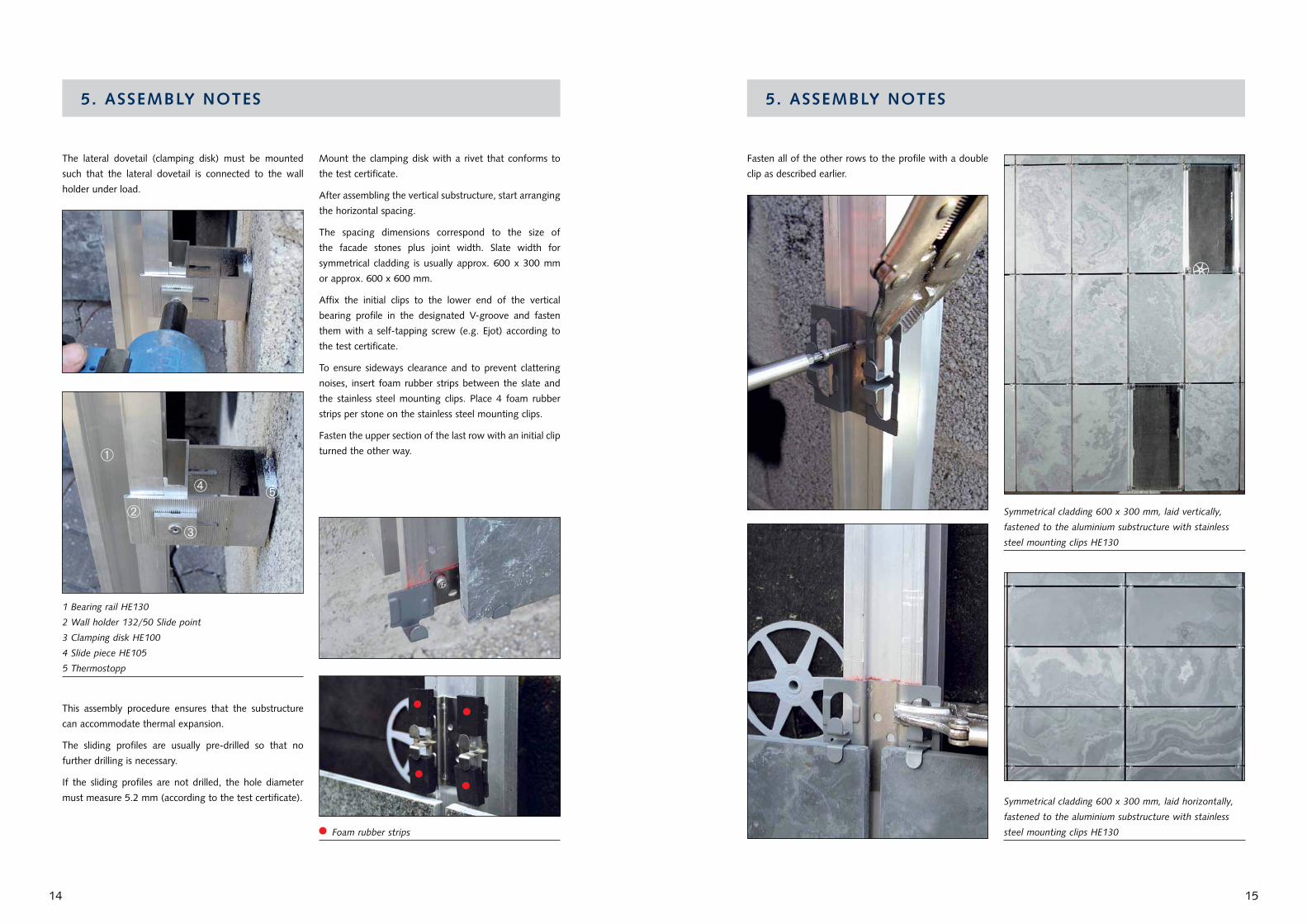
The lateral dovetail (clamping disk) must be mounted
such that the lateral dovetail is connected to the wall
holder under load.
1 Bearing rail HE130
2 Wall holder 132/50 Slide point
3 clamping disk HE100
4 Slide piece HE105
5 Thermostopp
This assembly procedure ensures that the substructure
can accommodate thermal expansion.
The sliding profiles are usually pre-drilled so that no
further drilling is necessary.
If the sliding profiles are not drilled, the hole diameter
must measure 5.2 mm (according to the test certificate).
Mount the clamping disk with a rivet that conforms to
the test certificate.
After assembling the vertical substructure, start arranging
the horizontal spacing.
The spacing dimensions correspond to the size of
the facade stones plus joint width. Slate width for
symmetrical cladding is usually approx. 600 x 300 mm
or approx. 600 x 600 mm.
Affix the initial clips to the lower end of the vertical
bearing profile in the designated V-groove and fasten
them with a self-tapping screw (e.g. Ejot) according to
the test certificate.
To ensure sideways clearance and to prevent clattering
noises, insert foam rubber strips between the slate and
the stainless steel mounting clips. Place 4 foam rubber
strips per stone on the stainless steel mounting clips.
Fasten the upper section of the last row with an initial clip
turned the other way.
Foam rubber strips
Fasten all of the other rows to the profile with a double
clip as described earlier.
Symmetrical cladding 600 x 300 mm, laid vertically,
fastened to the aluminium substructure with stainless
steel mounting clips HE130
Symmetrical cladding 600 x 300 mm, laid horizontally,
fastened to the aluminium substructure with stainless
steel mounting clips HE130

Slate is a natural product. irregularities in colour
and structure may occur. These nuances and the
individual appearance of each stone make up the
charm of slate cladding.
© b
y R
aths
chec
k. S
ubje
ct t
o re
visi
on. 0
7/20
12
InterSIN® blue-grey, natural
InterSIN® blue-grey, polished
ColorSIN® polar green, natural
ColorSIN® polar green, polished
ColorSIN® dark-green, natural
Rathscheck Schiefer und dach-Systeme
St.-Barbara-Straße 3 D-56727 Mayen-Katzenberg Germany
Telefon +49 (0)26 51/955- 0 Telefax +49 (0)26 51/955-100
[email protected] www.rathscheck.com