Symmetric Cluster Architecture and Component Technical ...
78
Symmetric Cluster Architecture and Component Technical Specifications David Teigland Red Hat, Inc. version 3.0 June 29, 2004
Transcript of Symmetric Cluster Architecture and Component Technical ...

Symmetric Cluster Architecture
and Component Technical Specifications
David TeiglandRed Hat, Inc.
version 3.0June 29, 2004

1
Revision History1.0 5/2002 ”Framework for Cluster Software Components”2.0 6/2002 ”Cluster Systems - Concepts and Components”3.0 9/2003 ”Symmetric Cluster Architecture”

Contents
1 Symmetric Cluster Architecture 3
1.1 Introduction . . . . . . . . . . . . . . . . . . . . . . . . . . . . . . . . . . . . . . . . . . . . . . 3
1.2 Background . . . . . . . . . . . . . . . . . . . . . . . . . . . . . . . . . . . . . . . . . . . . . . 3
1.3 Architecture Design Principles and Goals . . . . . . . . . . . . . . . . . . . . . . . . . . . . . 4
1.4 Component Definitions . . . . . . . . . . . . . . . . . . . . . . . . . . . . . . . . . . . . . . . . 5
1.5 GFS Requirements . . . . . . . . . . . . . . . . . . . . . . . . . . . . . . . . . . . . . . . . . . 6
1.6 Concepts . . . . . . . . . . . . . . . . . . . . . . . . . . . . . . . . . . . . . . . . . . . . . . . 7
2 Functional Descriptions 9
2.1 CCS . . . . . . . . . . . . . . . . . . . . . . . . . . . . . . . . . . . . . . . . . . . . . . . . . . 9
2.2 CMAN . . . . . . . . . . . . . . . . . . . . . . . . . . . . . . . . . . . . . . . . . . . . . . . . . 9
2.2.1 Connection Manager . . . . . . . . . . . . . . . . . . . . . . . . . . . . . . . . . . . . . 9
2.2.2 Service Manager . . . . . . . . . . . . . . . . . . . . . . . . . . . . . . . . . . . . . . . 10
2.3 GDLM . . . . . . . . . . . . . . . . . . . . . . . . . . . . . . . . . . . . . . . . . . . . . . . . . 14
2.3.1 Lock Spaces . . . . . . . . . . . . . . . . . . . . . . . . . . . . . . . . . . . . . . . . . . 14
2.3.2 Lock Requests and Conversions . . . . . . . . . . . . . . . . . . . . . . . . . . . . . . . 14
2.3.3 Callbacks . . . . . . . . . . . . . . . . . . . . . . . . . . . . . . . . . . . . . . . . . . . 15
2.3.4 Node Failure . . . . . . . . . . . . . . . . . . . . . . . . . . . . . . . . . . . . . . . . . 15
2.4 LOCK DLM . . . . . . . . . . . . . . . . . . . . . . . . . . . . . . . . . . . . . . . . . . . . . 15
2.5 Fence System . . . . . . . . . . . . . . . . . . . . . . . . . . . . . . . . . . . . . . . . . . . . . 16
2

3
3 Technical Designs and Specifications 17
3.1 CCS . . . . . . . . . . . . . . . . . . . . . . . . . . . . . . . . . . . . . . . . . . . . . . . . . . 17
3.1.0.1 User Interface . . . . . . . . . . . . . . . . . . . . . . . . . . . . . . . . . . . 17
3.1.0.2 Application Interface . . . . . . . . . . . . . . . . . . . . . . . . . . . . . . . 17
3.1.0.3 Special CMAN Usage . . . . . . . . . . . . . . . . . . . . . . . . . . . . . . . 17
3.1.0.4 Config Updates . . . . . . . . . . . . . . . . . . . . . . . . . . . . . . . . . . . 17
3.2 CMAN . . . . . . . . . . . . . . . . . . . . . . . . . . . . . . . . . . . . . . . . . . . . . . . . . 18
3.2.1 Cluster User Interface . . . . . . . . . . . . . . . . . . . . . . . . . . . . . . . . . . . . 18
3.2.2 Cluster Application Interface . . . . . . . . . . . . . . . . . . . . . . . . . . . . . . . . 18
3.2.2.1 Messages . . . . . . . . . . . . . . . . . . . . . . . . . . . . . . . . . . . . . . 19
3.2.2.2 Information . . . . . . . . . . . . . . . . . . . . . . . . . . . . . . . . . . . . . 19
3.2.3 Node Information . . . . . . . . . . . . . . . . . . . . . . . . . . . . . . . . . . . . . . 21
3.2.4 Membership . . . . . . . . . . . . . . . . . . . . . . . . . . . . . . . . . . . . . . . . . . 21
3.2.4.1 Joining the cluster . . . . . . . . . . . . . . . . . . . . . . . . . . . . . . . . . 21
3.2.4.2 Heartbeats . . . . . . . . . . . . . . . . . . . . . . . . . . . . . . . . . . . . . 21
3.2.4.3 Leaving the cluster . . . . . . . . . . . . . . . . . . . . . . . . . . . . . . . . 22
3.2.5 Transitions . . . . . . . . . . . . . . . . . . . . . . . . . . . . . . . . . . . . . . . . . . 22
3.2.6 Quorum . . . . . . . . . . . . . . . . . . . . . . . . . . . . . . . . . . . . . . . . . . . . 22
3.2.6.1 Quorum device . . . . . . . . . . . . . . . . . . . . . . . . . . . . . . . . . . . 23
3.2.6.2 Two-node clusters . . . . . . . . . . . . . . . . . . . . . . . . . . . . . . . . . 23
3.2.7 Event Notification . . . . . . . . . . . . . . . . . . . . . . . . . . . . . . . . . . . . . . 24
3.2.7.1 Kernel callbacks . . . . . . . . . . . . . . . . . . . . . . . . . . . . . . . . . . 24
3.2.7.2 Userland signals . . . . . . . . . . . . . . . . . . . . . . . . . . . . . . . . . . 25
3.2.7.3 Service Manager control . . . . . . . . . . . . . . . . . . . . . . . . . . . . . . 25
3.2.8 Barriers . . . . . . . . . . . . . . . . . . . . . . . . . . . . . . . . . . . . . . . . . . . . 25
3.2.9 Communications . . . . . . . . . . . . . . . . . . . . . . . . . . . . . . . . . . . . . . . 26
3.2.10 Services . . . . . . . . . . . . . . . . . . . . . . . . . . . . . . . . . . . . . . . . . . . . 27
4
3.2.11 Service API . . . . . . . . . . . . . . . . . . . . . . . . . . . . . . . . . . . . . . . . . . 27
3.2.11.1 Service formation . . . . . . . . . . . . . . . . . . . . . . . . . . . . . . . . . 27
3.2.11.2 Service control . . . . . . . . . . . . . . . . . . . . . . . . . . . . . . . . . . . 28
3.2.12 Service Events . . . . . . . . . . . . . . . . . . . . . . . . . . . . . . . . . . . . . . . . 29
3.3 GDLM . . . . . . . . . . . . . . . . . . . . . . . . . . . . . . . . . . . . . . . . . . . . . . . . . 30
3.3.1 Motivation . . . . . . . . . . . . . . . . . . . . . . . . . . . . . . . . . . . . . . . . . . 30
3.3.2 Requirements . . . . . . . . . . . . . . . . . . . . . . . . . . . . . . . . . . . . . . . . . 31
3.3.3 Lock Spaces . . . . . . . . . . . . . . . . . . . . . . . . . . . . . . . . . . . . . . . . . . 32
3.3.3.1 Usage . . . . . . . . . . . . . . . . . . . . . . . . . . . . . . . . . . . . . . . . 32
3.3.3.2 Functions: lockspace handling . . . . . . . . . . . . . . . . . . . . . . . . . . 32
3.3.4 Resources, Locks and Queues . . . . . . . . . . . . . . . . . . . . . . . . . . . . . . . . 33
3.3.4.1 Lock ID’s . . . . . . . . . . . . . . . . . . . . . . . . . . . . . . . . . . . . . . 34
3.3.4.2 Functions: RSB/LKB structures . . . . . . . . . . . . . . . . . . . . . . . . . 35
3.3.5 Cluster Management . . . . . . . . . . . . . . . . . . . . . . . . . . . . . . . . . . . . . 36
3.3.5.1 Functions: node information . . . . . . . . . . . . . . . . . . . . . . . . . . . 36
3.3.5.2 Control mechanics . . . . . . . . . . . . . . . . . . . . . . . . . . . . . . . . . 37
3.3.5.3 Recovery states . . . . . . . . . . . . . . . . . . . . . . . . . . . . . . . . . . 39
3.3.5.4 Functions: recovery management . . . . . . . . . . . . . . . . . . . . . . . . . 39
3.3.5.5 Cluster information . . . . . . . . . . . . . . . . . . . . . . . . . . . . . . . . 41
3.3.6 Lock Requests . . . . . . . . . . . . . . . . . . . . . . . . . . . . . . . . . . . . . . . . 41
3.3.6.1 Usage . . . . . . . . . . . . . . . . . . . . . . . . . . . . . . . . . . . . . . . . 41
3.3.6.2 Request processing . . . . . . . . . . . . . . . . . . . . . . . . . . . . . . . . . 44
3.3.6.3 Unlock request processing . . . . . . . . . . . . . . . . . . . . . . . . . . . . . 50
3.3.6.4 Canceling a request . . . . . . . . . . . . . . . . . . . . . . . . . . . . . . . . 51
3.3.6.5 AST handling . . . . . . . . . . . . . . . . . . . . . . . . . . . . . . . . . . . 52
3.3.7 Resource Directory . . . . . . . . . . . . . . . . . . . . . . . . . . . . . . . . . . . . . . 52
3.3.7.1 Removing entries . . . . . . . . . . . . . . . . . . . . . . . . . . . . . . . . . . 53

5
3.3.7.2 Functions: resource directory . . . . . . . . . . . . . . . . . . . . . . . . . . . 54
3.3.8 Hierarchical Locking . . . . . . . . . . . . . . . . . . . . . . . . . . . . . . . . . . . . . 54
3.3.8.1 Usage . . . . . . . . . . . . . . . . . . . . . . . . . . . . . . . . . . . . . . . . 55
3.3.8.2 Resource tree structure . . . . . . . . . . . . . . . . . . . . . . . . . . . . . . 55
3.3.9 Lock Value Blocks . . . . . . . . . . . . . . . . . . . . . . . . . . . . . . . . . . . . . . 56
3.3.9.1 Usage . . . . . . . . . . . . . . . . . . . . . . . . . . . . . . . . . . . . . . . . 56
3.3.9.2 Value block copying . . . . . . . . . . . . . . . . . . . . . . . . . . . . . . . . 56
3.3.10 Lock Ranges . . . . . . . . . . . . . . . . . . . . . . . . . . . . . . . . . . . . . . . . . 57
3.3.10.1 Usage . . . . . . . . . . . . . . . . . . . . . . . . . . . . . . . . . . . . . . . . 57
3.3.11 Deadlock . . . . . . . . . . . . . . . . . . . . . . . . . . . . . . . . . . . . . . . . . . . 57
3.3.12 Recovery . . . . . . . . . . . . . . . . . . . . . . . . . . . . . . . . . . . . . . . . . . . 58
3.3.12.1 Blocking requests . . . . . . . . . . . . . . . . . . . . . . . . . . . . . . . . . 58
3.3.12.2 Update node list . . . . . . . . . . . . . . . . . . . . . . . . . . . . . . . . . . 59
3.3.12.3 Rebuild resource directory . . . . . . . . . . . . . . . . . . . . . . . . . . . . 59
3.3.12.4 Clear defunct requests . . . . . . . . . . . . . . . . . . . . . . . . . . . . . . . 59
3.3.12.5 Mark requests to resend . . . . . . . . . . . . . . . . . . . . . . . . . . . . . . 60
3.3.12.6 Clear defunct locks . . . . . . . . . . . . . . . . . . . . . . . . . . . . . . . . 60
3.3.12.7 Update resource masters . . . . . . . . . . . . . . . . . . . . . . . . . . . . . 61
3.3.12.8 Rebuild locks on new masters . . . . . . . . . . . . . . . . . . . . . . . . . . . 61
3.3.12.9 Finish and cleanup . . . . . . . . . . . . . . . . . . . . . . . . . . . . . . . . . 62
3.3.12.10 Event waiting . . . . . . . . . . . . . . . . . . . . . . . . . . . . . . . . . . . 62
3.3.12.11 Functions: Request queue . . . . . . . . . . . . . . . . . . . . . . . . . . . . . 63
3.3.12.12 Functions: Nodes list . . . . . . . . . . . . . . . . . . . . . . . . . . . . . . . 63
3.3.12.13 Functions: Resource directory . . . . . . . . . . . . . . . . . . . . . . . . . . 63
3.3.12.14 Functions: Lock queue . . . . . . . . . . . . . . . . . . . . . . . . . . . . . . 64
3.3.12.15 Functions: Purging locks . . . . . . . . . . . . . . . . . . . . . . . . . . . . . 64
3.3.12.16 Functions: Updating resource masters . . . . . . . . . . . . . . . . . . . . . . 64
6
3.3.12.17 Functions: Recover list . . . . . . . . . . . . . . . . . . . . . . . . . . . . . . 65
3.3.12.18 Functions: Rebuilding locks . . . . . . . . . . . . . . . . . . . . . . . . . . . . 65
3.3.12.19 Functions: Event waiting . . . . . . . . . . . . . . . . . . . . . . . . . . . . . 67
3.3.13 Communications . . . . . . . . . . . . . . . . . . . . . . . . . . . . . . . . . . . . . . . 67
3.3.13.1 Sending requests . . . . . . . . . . . . . . . . . . . . . . . . . . . . . . . . . . 67
3.3.13.2 Receiving requests . . . . . . . . . . . . . . . . . . . . . . . . . . . . . . . . . 68
3.3.13.3 Recovery requests . . . . . . . . . . . . . . . . . . . . . . . . . . . . . . . . . 68
3.3.13.4 Functions: low-level communications . . . . . . . . . . . . . . . . . . . . . . . 68
3.3.13.5 Functions: mid-level communications . . . . . . . . . . . . . . . . . . . . . . 69
3.3.13.6 Functions: recovery communications . . . . . . . . . . . . . . . . . . . . . . . 70
3.3.14 Future Work . . . . . . . . . . . . . . . . . . . . . . . . . . . . . . . . . . . . . . . . . 70
3.4 LOCK DLM . . . . . . . . . . . . . . . . . . . . . . . . . . . . . . . . . . . . . . . . . . . . . 70
3.5 Fence . . . . . . . . . . . . . . . . . . . . . . . . . . . . . . . . . . . . . . . . . . . . . . . . . 70
3.6 Appendix A: Practical Usage . . . . . . . . . . . . . . . . . . . . . . . . . . . . . . . . . . . . 71
3.7 Appendix B: Service Group Examples . . . . . . . . . . . . . . . . . . . . . . . . . . . . . . . 71

Chapter 1
Symmetric Cluster Architecture
1.1 Introduction
The Symmetric Cluster Architecture is a design for software components that together support the GFS andCLVM clustering products.
This design document begins with architectural requirements, motivations and definitions of components. Itcontinues with functional descriptions of the components and ends with detailed technical design specifica-tions.
1.2 Background
The project of defining and implementing this cluster architecture began in 2000/2001. It has been reviewedand revised at many levels in parallel with development. The earliest development (2000) was on theConnection Manager portion of the CMAN cluster manager. The latest development was on the GDLMlock manager that had a late start (5/02) because of an aborted plan to adopt an open source DLM fromIBM. Some of the results of this architecture have made their way into earlier products (most notably CCSand the general cluster and node properties defined in configuration files.)
The years of research and education leading up to this architectural design produced dramatically new levelsof understanding about this software and what it required. Early knowledge about the problems being solvingwas primitive but evolved through lengthy experimentation and study to the point where this comprehensive,top-down design could be undertaken.
Early GFS concepts revolved around storing GFS lock state in storage devices using special SCSI commands(DLOCK/DMEP). These ideas were accompanied by little to no understanding of what cluster managementmeant or what would be required to correctly support GFS. As we came to realize new extents of the problem,various aspects to clustering were forced into the DLOCK/DMEP locking system (and even protocol). Wewere slowly discovering that GFS would require far more advanced locking and clustering support than couldrealistically be provided by SCSI-based device locks.
Hardware devices that implemented the DLOCK/DMEP commands were scarce to non-existent. To developand test GFS without the necessary hardware, we created small network servers to emulate a DLOCK/DMEP
7

8
device. Switching between DLOCK/DMEP hardware and emulators motivated the invention of the GFSLock Harness API. One lock module could send requests to an actual DLOCK/DMEP device and anothercould send requests to a network server. The servers were antithetical to GFS’s symmetric philosophy andchief selling points, of course, but they were merely for development purposes.
Eventually we realized that DMEP hardware devices would not become a reality. This was about the sametime we needed to release GFS to customers. Dismayed, we were forced to require customers to use theDMEP emulator. We had long known that the alternative to device locking was a Distributed Lock Manager(DLM) but it had now become a pressing need. We had neither time nor expertise to develop one ourselves,so we began a search to adopt a DLM from elsewhere.
Meanwhile, with customers left using the DMEP emulator there were some simple things we could do toimprove its performance. Mainly, this meant not strictly adhering to the DMEP protocol which among otherthings did not allow for callbacks. The result of these lock server improvements was called GULM and iteventually replaced the DMEP emulator.
The DLM search ended when IBM released some DLM code as open source. We jumped on this and beganworking with it in the hope that it could be linked with GFS in very short order. After several months,however, we realized the IBM DLM had serious problems and would need extensive engineering work fromus to be useful. We decided instead to develop our own DLM from scratch.
The larger architecture design and CMAN developments had continued throughout the process of findinga DLM. One of the first architectural principles had been that the cluster manager must be a unique,symmetric, stand-alone entity that would independently support any lock manager, GFS and CLVM. It wasnearly complete, allowing us to focus on DLM development.
Faced with the development time of the DLM and customer intolerance for the DLOCK/DMEP/GULMlineage of server-based locking, it was decided to add basic fail-over to GULM to keep customers interestedwhile the distributed clustering and locking subsystems were finished.
DLM development has been completed providing the full set of symmetric clustering and locking subsystemsto support GFS and CLVM.
1.3 Architecture Design Principles and Goals
There are a few general ideas that guide the development of the architectural components.
1. Symmetry
Symmetry has long been a chief design principle of our clustering products. Each component of thisarchitecture has been designed from the start with this symmetry in mind. As such, the componentswhen combined produce a uniformly symmetric system as a whole, exploiting to the fullest extent theadvantages inherent in such architectures.
2. Modularity
A second key advantage distinguishing GFS in the past has been its modularity. This allows GFS toadapt quickly to new environments and makes it exceedingly extensible. Modular components can alsobe shared among products avoiding duplication and allowing products to work together (e.g. CLVMand GFS using common subsystems). This architecture furthers the modular tradition, understandingand defining new components from its inception.
9
3. Simplicity
The clustering products should remain simple, conceptually and from a management perspective. Anoverly complex architecture makes the products difficult to understand and use and prohibits them frombeing easily extended or adapted in the future. The symmetry principle supports this to a large extentas symmetric clusters are far simpler conceptually (although often more difficult to design technically.)
4. Correctness
Customers place high trust in the software that manages their data. They must believe that thesoftware will not corrupt the data or simply lose it. Even one case of a customer losing data canhave devastating effect on our reputation. Every scenario where safety is at risk has been thoroughlyinvestigated and addressed in this design.
1.4 Component Definitions
The Symmetric Cluster Architecture defines the following distinct software components. Each componenthas its own functional requirements and design. The components are defined here with respect to theirdependence on the others.
CCS Cluster Configuration SystemCMAN Cluster ManagerFENCE I/O Fencing SystemGDLM Global Distributed Lock ManagerLOCK DLM GFS Lock Module for the DLMGFS Global File SystemCLVM Cluster Logical Volume Manager
The modular components are clearly separate in function so they can form the basis of multiple products.
CCS
– Depends on no other component (for basic function).
– Provides static configuration parameters to other components.
CMAN
– Depends on CCS for cluster and node identifiers.
– Provides cluster and service management to Fence, GDLM, GFS/LOCK DLM, and CLVM.
FENCE
– Depends on CCS for node fencing parameters and fence device parameters. Depends on CMANfor cluster management.
– Provides I/O Fencing for GFS/LOCK DLM and CLVM.
GDLM
– Depends on CMAN for cluster management.
– Provides lock management for GFS/LOCK DLM and CLVM.
10
GFS/LOCK DLM
– Depends on CMAN for cluster management. Depends on Fence for I/O Fencing. Depends onGDLM for lock management.
– Provides nothing to other components.
CLVM
– Depends on CMAN for cluster management. Depends on GDLM for lock management.
– Provides nothing to other components.
1.5 GFS Requirements
This is an overview of GFS requirements. The specific requirements are covered in more depth in the laterdescriptions of how they are met.
GFS relies on external components to provide the following functions. They are provided to GFS througha ”lock module” plugged into GFS’s Lock Harness interface. In this architecture, the lock module isLOCK DLM. (The lock management requirements dominate the others – the term ”lock module” and theLOCK prefix reflect this.) LOCK DLM primarily acts as a bridge to the independent CMAN and GDLMclustering/locking managers, but GFS-specific semantics are implemented by the GFS lock module, not thegeneral lock manager.
1. Lock Management
Each GFS file system has a unique name specified when it’s created. This name is given to the lockmodule which must use it to associate different GFS file systems with unique lock spaces.
GFS’s locking requirements are standard and quite simple. A GFS node will only request a singlelock on a resource at once. Resources are uniquely identified by GFS using 12 bytes (binary datacomposed of two integers). GFS uses three lock modes: ”exclusive” and two shared modes (”shared”and ”deferred”) that are incompatible with each other and exclusive.
GFS lock and unlock requests are asynchronous. GFS provides a callback function for notificationof completed requests and for blocking callbacks. A blocking callback should be accompanied by themode of lock being requested.
Normal GFS requests can be modified by three flags. The first is a ”try” flag that indicates the requestshould not block if the lock cannot be immediately granted. Blocking callbacks should not be sent if the”try” request fails. The other two flags are optional and are used to enhance performance. The ”any”flag indicates that either of the shared modes may be granted – preferably the one compatible withexisting granted modes. The ”one cb” flag used with ”try” indicates that a single blocking callbackshould be sent if the request cannot be granted immediately.
GFS requires selected resources have a 32 byte value block available for reading and writing in con-junction with lock operations. The value should be written with the release of an exclusive lock andread when any lock is acquired. The value block should be cleared to zero if the most recent value islost during recovery.
GFS requires the lock module to avert conversion deadlock when locks are promoted. The lock manageris permitted, however, to release a lock in the process of promoting it if the result is subsequently flaggedto indicate that the lock was released.
GFS must be able to cancel an outstanding request. Once canceled a request should complete imme-diately. If the request was not successful the result must be flagged as having been canceled.
11
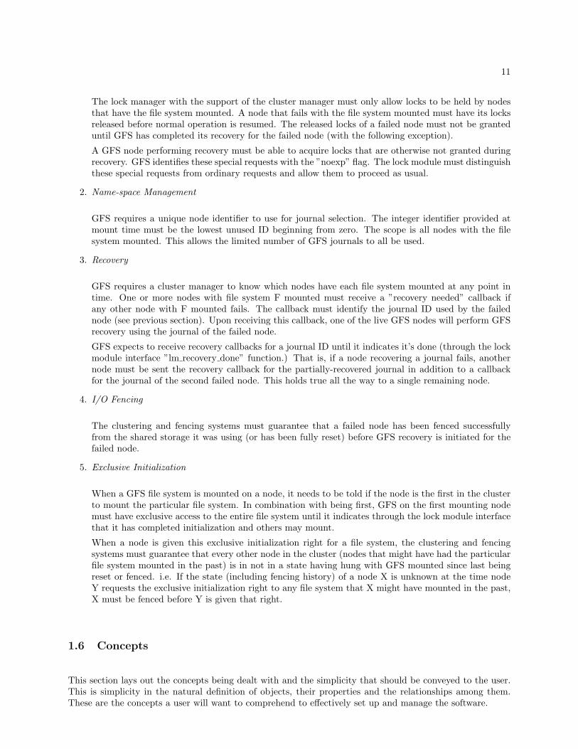
The lock manager with the support of the cluster manager must only allow locks to be held by nodesthat have the file system mounted. A node that fails with the file system mounted must have its locksreleased before normal operation is resumed. The released locks of a failed node must not be granteduntil GFS has completed its recovery for the failed node (with the following exception).
A GFS node performing recovery must be able to acquire locks that are otherwise not granted duringrecovery. GFS identifies these special requests with the ”noexp” flag. The lock module must distinguishthese special requests from ordinary requests and allow them to proceed as usual.
2. Name-space Management
GFS requires a unique node identifier to use for journal selection. The integer identifier provided atmount time must be the lowest unused ID beginning from zero. The scope is all nodes with the filesystem mounted. This allows the limited number of GFS journals to all be used.
3. Recovery
GFS requires a cluster manager to know which nodes have each file system mounted at any point intime. One or more nodes with file system F mounted must receive a ”recovery needed” callback ifany other node with F mounted fails. The callback must identify the journal ID used by the failednode (see previous section). Upon receiving this callback, one of the live GFS nodes will perform GFSrecovery using the journal of the failed node.
GFS expects to receive recovery callbacks for a journal ID until it indicates it’s done (through the lockmodule interface ”lm recovery done” function.) That is, if a node recovering a journal fails, anothernode must be sent the recovery callback for the partially-recovered journal in addition to a callbackfor the journal of the second failed node. This holds true all the way to a single remaining node.
4. I/O Fencing
The clustering and fencing systems must guarantee that a failed node has been fenced successfullyfrom the shared storage it was using (or has been fully reset) before GFS recovery is initiated for thefailed node.
5. Exclusive Initialization
When a GFS file system is mounted on a node, it needs to be told if the node is the first in the clusterto mount the particular file system. In combination with being first, GFS on the first mounting nodemust have exclusive access to the entire file system until it indicates through the lock module interfacethat it has completed initialization and others may mount.
When a node is given this exclusive initialization right for a file system, the clustering and fencingsystems must guarantee that every other node in the cluster (nodes that might have had the particularfile system mounted in the past) is in not in a state having hung with GFS mounted since last beingreset or fenced. i.e. If the state (including fencing history) of a node X is unknown at the time nodeY requests the exclusive initialization right to any file system that X might have mounted in the past,X must be fenced before Y is given that right.
1.6 Concepts
This section lays out the concepts being dealt with and the simplicity that should be conveyed to the user.This is simplicity in the natural definition of objects, their properties and the relationships among them.These are the concepts a user will want to comprehend to effectively set up and manage the software.

12
Entities
Cluster A group of nodes.Node A machine that can join and leave a cluster.Resource Something used by nodes in a cluster.Service A program run by nodes in a cluster. Often related to
accessing a resource.
Policies
• A node can be a member of one cluster.
• A resource belongs to one cluster.
• A node in a cluster can access the resources in the cluster.
• All nodes are equal.
• Access to shared resources is controlled by services running on the nodes.
• Arbitrary cluster members can start and stop using arbitrary cluster resources at any time withoutaffecting any other cluster members.
• The failure of a cluster member should only affect other cluster members that are using the sameshared resources as the failed node.
Properties
Cluster
– name: unique name
– members: list of nodes that are members
Node
– name: unique name
– cluster: the cluster the node is member of
Resource
– name: unique name
– cluster: the name of the cluster whose members can use the resource
Resources exist in many forms and at many levels. A resource could be a device, a file, a record, a piece ofmetadata, or any other entity that can be consistently named among nodes or processes. Services accessingshared resources often require synchronization involving some form of locking.
The generic properties of a service are not generally relevant when managing the system. The taxonomyabove is extended further in the area of services when describing the internal function of the cluster manager.

Chapter 2
Functional Descriptions
Description of purpose, main parts and functions of each component. Specific interface definitions andimplementation details are left for the technical design specifications.
2.1 CCS
CCS provides access to a single cluster configuration file. The CCS daemon (ccsd) running on each nodemanages this file and provides access to it. When ccsd is started it finds the most recent version of the fileamong the cluster nodes. It keeps the file in sync among nodes if updates are made to it while the clusteris running.
2.2 CMAN
The CMAN cluster manager has two parts: Connection Manager and Service Manager. The main require-ments of CMAN are to manage the membership of the cluster (connection manager) and to manage whichmembers are using which services (service manager). CMAN operates in the kernel and both parts arecompletely symmetric – every node is the same.
CMAN has no specific knowledge of higher level cluster services; it is an independent, stand-alone systemusing only CCS. As a general cluster manager it should naturally not function specifically for select higherlevel applications. While GFS, GDLM, CLVM, etc. can sit above it, CMAN can be used for entirely differentservices or purposes.
2.2.1 Connection Manager
Connection Manager (cnxman) tracks the liveness of all nodes through periodic ”HELLO” messages sentover the network. Cnxman’s list of current live nodes defines the membership of the cluster. Managingchanges to cluster membership is the main task of cnxman.
A node joins the cluster by broadcasting the cluster’s unique ID on the network. Other members of the13

14
cluster will accept the new node and add it to the membership list through a multi-step transition processwhereby all members agree on the new addition. Transitions are coordinated by a dynamically selectednode. The command ’cman_tool join’ will initiate this procedure on a node and cause the node to join thecluster.
A current member can leave the cluster by running the command ’cman_tool leave’. Again, the leave pro-cess involves a multi-step transition process through which all remaining members agree on the membershipchange. A node cannot leave the cluster (except by force) until all higher level clustering systems dependentupon CMAN have shut down.
The failure of a cluster node is detected when its HELLO messages are not received by other members fora predetermined number of seconds. When this happens, the remaining cluster members step through atransition process to remove the failed node from the membership list. A failed node can rejoin the clusteronce it has been reset.
The cnxman cluster can suffer from a ”split-brain” condition in the event of a network partition. Two groupsof nodes can both form a cluster of the same name. If both clusters were to access the same shared data,it would be corrupted. Therefore, cnxman must guarantee, using a quorum majority voting scheme, thatonly one of the two split clusters becomes active. This means that to safely cope with split-brain scenarios,cnxman must only enable cluster services when over half (a majority) of nodes are members. This behaviorcan be modified by assigning an unequal number of votes to different machines.
To join the CMAN cluster, the cman_tool program gets the unique cluster name from the cluster configu-ration file (through CCS.) This means that the definitive step of associating a node with a particular clustercomes when the CCS daemon selects a cluster configuration file to use. Only nodes named in the clusterconfiguration can join the cluster.
When a node joins the cluster, cnxman assigns it a unique, non-zero node ID (integers beginning with 1).Once assigned, a node will retain its node ID for the life of the cluster – if the node leaves and rejoins thesame cluster it will have the same ID (cnxman does not reuse node ID’s for different nodes). Exportedcnxman functions can be used to get a listing of all nodes, current members, or to look up node information(name, IP address, etc).
2.2.2 Service Manager
Service Manager (SM) manages which nodes are using which services. It uses ”Service Groups” to representdifferent instances of services operating on dynamic groups of nodes in the cluster.
In the case of a symmetric service where all nodes can produce results independently, it is critical that allnodes running the service agree on the service group membership while any are producing results. Theservice group membership is often a factor determining the output of the cluster service – any disagreementcan result in inconsistent output. Because of this, the operation of the service must be temporarily suspendedwhen the group of nodes running the service changes. When the new group comes to agreement on the newgroup membership, the operation of the service can be resumed 1.
It will be useful to add concepts associated with services to the definitions presented earlier. The new entitiesare defined, along with their properties, followed by some general rules governing them.
1In a client-server architecture, the essential management and recovery functions, into which the group membership factor,occur on the server only. Clients do not make independent decisions based on factors like service group membership, even ifthey keep their own record of the nodes copied from the server. A transition from one membership group to another (includingnecessary adjustments within effected services) occurs on the server without stopping the service on all clients. Replies to clientrequests may at most be delayed momentarily as the server makes the adjustment.
15
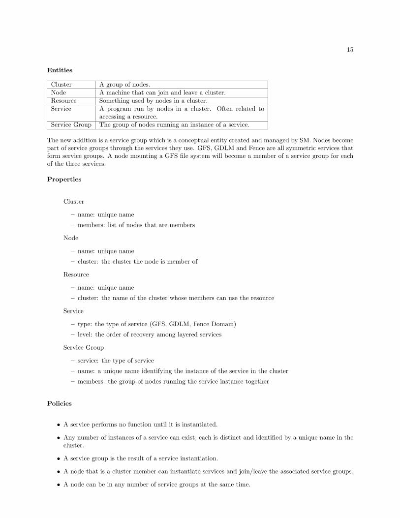
Entities
Cluster A group of nodes.Node A machine that can join and leave a cluster.Resource Something used by nodes in a cluster.Service A program run by nodes in a cluster. Often related to
accessing a resource.Service Group The group of nodes running an instance of a service.
The new addition is a service group which is a conceptual entity created and managed by SM. Nodes becomepart of service groups through the services they use. GFS, GDLM and Fence are all symmetric services thatform service groups. A node mounting a GFS file system will become a member of a service group for eachof the three services.
Properties
Cluster
– name: unique name
– members: list of nodes that are members
Node
– name: unique name
– cluster: the cluster the node is member of
Resource
– name: unique name
– cluster: the name of the cluster whose members can use the resource
Service
– type: the type of service (GFS, GDLM, Fence Domain)
– level: the order of recovery among layered services
Service Group
– service: the type of service
– name: a unique name identifying the instance of the service in the cluster
– members: the group of nodes running the service instance together
Policies
• A service performs no function until it is instantiated.
• Any number of instances of a service can exist; each is distinct and identified by a unique name in thecluster.
• A service group is the result of a service instantiation.
• A node that is a cluster member can instantiate services and join/leave the associated service groups.
• A node can be in any number of service groups at the same time.

16
• An instance of a service is identified by a unique name in the cluster. Any cluster member instantiatingand joining a service of the same type and name will be in the same service group.
• To use a resource, a node may be part of multiple service groups, each controlling a different aspect ofsharing the resource.
• The unique name of a service instance is often based on the name of the shared resource to which theservice is supporting access.
One part of the Service Manager function should already be clear. SM is in charge of managing service groupsin the cluster. This involves instantiating them, managing nodes joining and leaving them, and managingthe recovery of the appropriate service groups when cluster nodes fail.
If a program needs to be cluster-aware and know which nodes are running it, it can become a SM servicewith its instantiations managed as service groups. This can be done using the SM API detailed later. Whatit means for a program to be under the management of SM is the topic of the next section.
Service Control
When we say that a service requires ”cluster management” we are referring to the fact that the service needsto respond to certain cluster events as they occur. When a service registers to be managed/controlled bySM, it provides a set of callback functions through which the SM can manage it given cluster events affectingit. We refer to the use of these callback management functions as service ”control”. There are three controlmethods that apply to services:
1. stop - suspend - membership of the service group will be changed.
2. start - recover - begin any recovery necessary given the new service group members.
3. finish - resume - all service group members have completed start.
When a service receives a ”stop” it is aware that other services will be reconfiguring themselves (recovering)and may produce results inconsistent with the previous configuration of the cluster. The service is alsoaware that it will be reconfigured itself and must not produce any results assuming a particular servicegroup membership.
When a service receives a ”start” it knows that other services at a lower level have completed their recoveryare are in a reliable state. It also knows that all nodes in the service group have received a stop, i.e. when itstarts it knows that no other group members will be operating based on the previous membership. The newlist of service group members is provided with the start. This service can now do its own recovery. Whendone starting, the service notifies SM through an API callback function.
When a service receives a ”finish” it knows that all other members of the service group have completed theirstart. Any recovery state can be cleared. (Recovery state may need to be maintained until finish is receiveddue to the fact that a service group member may fail while starting.) The service can safely resume normaloperation, aware that all service group members have recovered in agreement.
The three functions are ordinarily received by a service in order, but a stop can be received while starting ifa node in the group fails during start. Specific guarantees about the sequence and ordering of these controlfunctions as seen by a service will be given later.
Service Events
A service event is an occasion where a service group transitions from one set of members to a different set ofmembers. A complete event entails stop, start and finish. A service event is caused by one of the following:

17
• A node joins the service group.
• A node leaves the service group.
• A node in the service group fails.
At present, SM allows one node to join or leave a service group at a time. Not until a currently joining orleaving node has finished will another node be permitted to begin joining or leaving. Enhancements can beadded to overcome the limitations of this serialization.
A Connection Manager transition occurs when a cluster member fails or a node joins or leaves the cluster.At the end of one of these transitions, the Service Manager is notified of the change. The only change thatinterests SM is the failure of a cluster member. When this happens, SM looks through all service groups tofind if the failed node is a member of any. Any service group the failed node is part of is subject to a serviceevent to remove the node and recover the service on the remaining service group members.
As was briefly mentioned in the Connection Manager’s quorum description, SM will not start cluster servicesif the Connection Manager determines that quorum is lost. While quorum is lost, stopped service groupsremain stopped but some service groups remain running (not stopped) because they were unaffected by thespecific node failure (the failed node wasn’t in the service group). When quorum is regained by a nodejoining the cnxman cluster (or intervention to reduce the number of expected votes), SM service events willcontinue with any stopped services being started.
These methods prevent services from being started in two split-brain clusters. However, an uneffected servicemay have continued running in the original inquorate cluster while the same service is to be started in thenew, split, quorate cluster. Corruption of shared data is averted because the first service to be started inthe new cluster is the fencing service. When the fencing service is started it fences all the nodes partitionedin the original inquorate cluster. Their access to shared storage will therefore be cut off before the sameservices are started in the new cluster.
Layered Services
A fundamental issue in the cluster architecture design has emerged; it is that of ”layered services”. Servicesoften have a dependence upon each other. This creates layers of services where one layer relies on the layerbelow it to operate. Coordinating all the levels is the job of the cluster manager. The cluster managerrelies functionally on no other cluster components and controls all the other clustering services based on itsfirst-hand knowledge of node state, relative service levels and service group membership.
A service has an intrinsic level based on its function. Lower level services provide functions for higher levelservices. During recovery the service manager starts services from lowest level to highest. A high level servicecould not start if the service it depends on has not yet started. (Multiple services can exist at the same leveland are started at once.)
GFS/LOCK DLM relies upon the Fencing service and the GDLM service to be completely recovered andfully operational before it begins its own recovery. Therefore, both Fence and GDLM are lower service levels.
Service Types
The following table shows what constitutes a service group for each service type.
• A ”Fence Domain” (FD) is a service group created by the Fence service.
• A ”Lock Space” (LS) is a service group created by the GDLM service.

18
• A ”Mount Group” (MG) is a service group created by the LOCK DLM service.
• A FD’s function is to I/O fence service group members that fail.
• A LS’s function is to manage locks held by service group members.
• A MG’s function is to send GFS recovery callbacks for service group members that fail.
2.3 GDLM
The GDLM lock manager is a VMS-like distributed lock manager. It follows the traditional VaxClusterDLM model that many other commercial DLM’s have copied. The locking and recovery methods are notparticular to GFS or CLVM or any other application. GDLM was designed to depend only on the clustermanager (CMAN) and can be used independently of any other systems.
In both the kernel and user space, GDLM exports a standard locking API that is as comprehensive as anyapplication would generally require. GDLM distinct features are the algorithms used internally to distributethe lock management across all nodes in the cluster removing bottlenecks while remaining fully recoverablegiven the failure of any node or number of nodes.
2.3.1 Lock Spaces
Applications can create and use their own GDLM lock spaces (minor applications can use a common ”default”lock space). GDLM will return a lock space context pointer to any application that requests a lock spacewith an arbitrary name. There is no limit to the number of lock spaces that can be created and used on asingle node or throughout the cluster.
Application instances on the same or different nodes in the cluster requesting lock spaces with the samename will be a part of the same lock space. Each lock space can be created with specific features enabledor disabled. GFS, for example, creates lock spaces for each of its file systems with the NOTIMERS flag setindicating that GDLM should not return lock requests that have been waiting, ungranted, for too long.
2.3.2 Lock Requests and Conversions
Locks of a specified mode are requested against a named resource. GDLM’s maximum resource name lengthis 64 bytes (GFS uses 12 or 24 byte resource names, depending on encoding style). The resource name isnot interpreted by GDLM, but treated as 64 binary bytes of data.
There is no limit to the number of locks that can be held at once by the same or different nodes against aparticular resource. The first node requesting a lock against a resource becomes the resource’s master.
Locks with the following modes can be requested against resources: Null (NL), Concurrent Read (CR),Concurrent Write (CW), Protected Read (PR), Protected Write (PW), and Exclusive (EX). The standardcompatibility matrix for these modes is included in the technical specifications. GFS’s lock modes map toNL, EX, CW and PR.
Once a lock is obtained against a resource, it can either be converted to a different mode or unlocked. (Thecommon conversion semantics are different from the narrower semantics used by GFS, although a translation

19
can effectively be made between them.) To convert an existing lock, GDLM returns with the first request arandom ”lock ID” that is used to reference the lock in subsequent requests.
A lock request can optionally specify a range. By default when no range is specified, the full range isassumed. Multiple nodes can hold exclusive locks with non-overlapping ranges against a resource at once. Alock request can also specify a Lock Value Block (LVB): 32 bytes of arbitrary data associated with a resourcethat can be saved and retrieved with a lock request. Finally, parent locks can be specified in lock requeststo form hierarchical resource trees. Each level of the tree has a separate name space.
Time-out based deadlock detection can be enabled or disabled per lock space with the time-out periodconfigurable in the configuration file. A per request flag can also be set that causes GDLM to detectconversion deadlock and resolve such events by temporarily demoting the granted mode of one or more locks(this is a GFS-oriented feature.)
The resource directory provides a simple mapping of resource names to resource masters. It is distributedacross all nodes in a lock space using a shared hash function on resource names. All nodes are presently givena directory weight of one resulting in equal distribution. (Configurable weights is a future enhancement.)
2.3.3 Callbacks
In DLM terminology, a callback is an AST (Asynchronous System Trap). An AST either reports thatan asynchronous lock request is complete or that an existing lock is blocking another lock that has beenrequested (a Blocking AST). The AST function called by GDLM is provided by the application with eachlock request. An AST argument is also provided that will be passed back to the application to identify thespecific lock.
2.3.4 Node Failure
There are very few if any interesting external issues involved in node failure or recovery. The lock managerwill not (and should not) impose any special policy or requirements related to recovery on the applications.
When a node in a GDLM lock space fails (or leaves the lock space voluntarily) the CMAN Service Managerrestarts the lock space with the new set of nodes in the lock space service group. This is all invisibleexternally. When GDLM adjusts to the new set of nodes (recovery), any locks held by previous nodes willsimply disappear and previously blocked requests will be granted.
2.4 LOCK DLM
LOCK DLM represents GFS in the symmetric clustering and locking world. It interacts with the externalGDLM lock manager, CMAN cluster manager and Fence system on behalf of GFS. It is primarily a bridgeinterfacing with the API’s of these other systems. There are some minor GFS-specific functions it implementsitself so that external managers remain general-purpose and not tied to a specific product.
To support GFS, LOCK DLM plugs into GFS’s Lock Harness, providing the full set of functions requiredby GFS. The LOCK DLM implementation of all these functions is detailed in the technical specifications.
At mount time for a specific GFS file system, LOCK DLM requires that the node already be a clustermember, otherwise the mount fails. If the node is a cluster member LOCK DLM adds a reference count to
20
the CMAN module preventing the node from leaving the cluster while GFS file systems dependent on thecluster are mounted. (Other subsystems relying on CMAN also add reference counts when started for thesame purpose.)
A second important check at mount time handled by LOCK DLM is that the cluster name encoded in thespecific file system’s superblock (by gfs mkfs) matches the name of the cluster the node is in. This check isnecessary to prevent nodes from different clusters from mounting the same file system at once and quicklycorrupting it.
With respect to locking, LOCK DLM creates a new GDLM lock space for each file system at mount time.The unique file system name (also available from the file system’s superblock) is used as the lock space name.With respect to fencing, LOCK DLM checks that the node is a member of a fence domain at mount time.If the node fails while the file system is mounted, the node will be fenced. LOCK DLM also creates itsown CMAN/SM Service Group at mount time which it calls a ”mount group”. The members of the mountgroup are the nodes with that specific file system currently mounted. Nodes in a LOCK DLM mount groupare responsible for recovering the GFS journals of other mount group members if they fail. In this regardLOCK DLM must also keep track of which journals the different mount group members are using.
2.5 Fence System
The fence daemon (fenced) must be started on each node after joining the cluster and before using GFS.Fenced determines which nodes to I/O fence based on the ”fence domain” (FD) membership. The defaultfence domain is a SM service group and the members are all nodes in the cluster running fenced.
When a node needs to be I/O fenced, fenced looks up the node-specific fencing parameters from CCS. Itthen calls the specified fence agent to carry out the actual fencing.
Once a node joins an FD it will be fenced by another FD member if it fails before leaving. In practice, nodesin the cluster join one common (”default”) FD before they use CLVM or a GFS file system. A node leavesthe default FD once it is done using CLVM/GFS – it can then be shut down without being fenced.
Any cluster member can join a fence domain and be subject to fencing, although it must be able to carryout fencing operations on any other fence domain members.
Chapter 3
Technical Designs and Specifications
3.1 CCS
The cluster configuration file is kept in the /etc/cluster/ directory on each cluster node. Managing andproviding access to this file is the job of the CCS daemon, ccsd.
3.1.0.1 User Interface
3.1.0.2 Application Interface
3.1.0.3 Special CMAN Usage
3.1.0.4 Config Updates
21
22
3.2 CMAN
CMAN is a general purpose, kernel based cluster manager designed to support other kernel and userlandsystems dependant on cluster information and event notification. CMAN is also symmetric and quorum-based; all cluster members are peers.
CMAN has two main parts, the Connection Manager (Cnxman) and the Service Manager (SM). Cnxmanmanages which nodes are in the cluster, handling things such as membership, transitions (joining and leavingthe cluster), and quorum. SM is quite separate and manages service groups instantiated by cluster servicesin the kernel and userland. Services are dynamically registered with SM and are thereafter controlled withstandard callback functions. SM defines ”Service Groups” where each service group represents a collectionof nodes using a particular instance of a service.
The Cnxman portion of CMAN is activated and begins managing membership as soon as a node joins thecluster. This is all that’s required for user level cluster information and notification to be available. Thecluster members, as reported by Cnxman, are simply all nodes that have joined the cluster.
The SM portion of CMAN will be unused on a node unless (until) a system that uses the SM is started.This does not affect the Cnxman operation at all. SM combines the cluster membership information fromCnxman with the particular service registrations to manage the Service Groups.
3.2.1 Cluster User Interface
A node must first join the cluster before any cluster services or applications will operate. To join the cluster,a node must simply run the command: cman_tool join. This tells the CMAN kernel module to initiate theprocess of joining the cluster. The command simply initiates the join process and returns before the processis complete.
Different clusters may exist on the same network and must be distinguishable, so a cluster is uniquelyidentified by a name defined in the cluster configuration file (see figure ??). The cman_tool program looksup this name (from the CCS system) to determine what cluster to join. A cluster is initially formed by thefirst node attempting to join it.
A cluster member can leave the cluster with the command: cman_tool leave. If other clustering systemsare still running on the node, this command will fail and report a ”busy” error (unless the force option isused.)
CMAN gets the local node name from system_utsname.nodename when the kernel module is loaded. Thisname can be changed through the cluster application interface covered below.
Cluster status and members, can be displayed on any member by viewing /proc/cluster/status and/proc/cluster/nodes.
3.2.2 Cluster Application Interface
CMAN has a cluster socket API to allow userspace to communicate with the cluster manager and also toprovide some basic inter-node communication facilities. This API is defined in the header file cnxman-socket.h and is summarized here 1.
1Information from Patrick Caulfield

23
To use the interface, a socket of address family AF CLUSTER and type SOCK DGRAM must be createdas shown in figure 3.1 using the socket(2) system call. The returned file descriptor can be used as usualwith ioctl and to send and receive data.
fd = socket(AF_CLUSTER, SOCK_DGRAM, CLPROTO_CLIENT);
Figure 3.1: Cluster socket creation
3.2.2.1 Messages
CMAN supports sending and receiving data between cluster members on its cluster sockets. This is not ahigh-speed bulk data channel. It is a packet based, reliable, unwindowed transport. Messages are limited to1500 bytes. Client applications bind to an 8-bit port number in a manner similar to IP sockets - only oneclient can be bound to a particular port at a time. Port numbers below 10 are special; activity on them willnot be blocked when the cluster is in transition or inquorate.
• sendmsg(2) is used to send messages to a specific node or to all other nodes in the cluster. The latterwill be sent as a broadcast/multicast message (depending on the cluster configuration) to all nodessimultaneously. Nodes are specified by their node ID rather than IP address.
• recvmsg(2) receives messages from other cluster members. The sockaddr is filled in with the node IDof the sending node. poll(2) is supported. recvmsg() can also receive informational messages whichare delivered as Out-Of-Band (OOB) messages if MSG OOB is passed to recvmsg().
3.2.2.2 Information
The following ioctl(2)’s are supported on cluster sockets to access cluster and node information.
• SIOCCLUSTER_NOTIFY
Tells CMAN to send the calling process a signal every time a node joins or leaves the cluster. Theargument passed is a signal number.
• SIOCCLUSTER_REMOVENOTIFY
Removes the signal notification.
• SIOCCLUSTER_GETMEMBERS
Returns a list of cluster members. The argument is either NULL (in which case the number of membersis returned) or a pointer to an array of struct cl_cluster_node which will be filled in.
• SIOCCLUSTER_GETALLMEMBERS
Same as previous, but also includes nodes that were previously members but are not any longer. Notethat this does not include configured nodes that have never joined the cluster, only nodes that wereonce part of the current cluster.
• SIOCCLUSTER_ISQUORATE
Returns 1 if the cluster is currently quorate, 0 if not.

24
• SIOCCLUSTER_ISACTIVE
Returns 1 if the node is a cluster member, 0 if not.
• SIOCCLUSTER_ISLISTENING
Returns 1 if a program on the specified node is listening on a given port number, 0 of not. Theparameter is a pointer to a struct cl_listen_request. This ioctl will wait until a response has beenreceived from the node or a cluster state transition occurs.
• SIOCCLUSTER_GET_VERSION
Returns the version number of the CMAN cluster software. The parameter is a struct cl_versionthat is filled in.
• SIOCCLUSTER_GET_JOINCOUNT
Returns the number of active cluster subsystems on this node. Once this ”join count” is zero, the nodecan properly leave the cluster.
• SIOCCLUSTER_BARRIER
Userspace interface to the barrier system. The parameter is a struct cl_barrier_info. See thekernel documentation for more information. CAP ADMIN privilege is needed for this operation. (Thisuserspace access to the barrier system is not fully tested.)
• SIOCCLUSTER_SET_VOTES
Changes the number of votes cast by this member of the cluster. Quorum will be recalculated and theother nodes notified. CAP ADMIN privilege is needed for this operation.
• SIOCCLUSTER_SETEXPECTED_VOTES
Changes the number of votes expected by the cluster. Quorum will be recalculated and the other nodesnotified. CAP ADMIN privilege is needed for this operation.
• SIOCCLUSTER_KILLNODE
Forcibly remove another member from the cluster. The parameter is a node number. CAP ADMINprivilege is needed for this operation.
• SIOCCLUSTER_SERVICE_REGISTER
Registers a service with the Service Manager. The parameter is the service name. The cluster socketitself identifies the user program to the SM in the kernel and must remain open for the lifetime of theservice program.
• SIOCCLUSTER_SERVICE_UNREGISTER
Unregisters a service with the Service Manager; takes no parameters apart from the cluster socket thatwas originally used to register the service.
• SIOCCLUSTER_SERVICE_JOIN
Instructs SM to join the service group for the registered service associated with the cluster socket.Takes no parameters.
• SIOCCLUSTER_SERVICE_LEAVE
Instructs SM to leave the service group for the registered and joined service associated with the clustersocket. Takes no parameters.
• SIOCCLUSTER_SERVICE_SETSIGNAL
Tells CMAN to deliver a signal to the calling process when a change occurs in the service groupmembership. The cluster socket must be associated with a registered service. The signal number isthe parameter.

25
• SIOCCLUSTER_SERVICE_STARTDONE
The service program must use this ioctl when it has completed processing a start event from SM. Theparameter is the event ID of the start event that was processed.
• SIOCCLUSTER_SERVICE_GETEVENT
Returns details of the next service event for the service group associated with the cluster socket. Theparameter is a struct cl_service_event.
• SIOCCLUSTER_SERVICE_GETMEMBERS
Returns struct cl_cluster_node details for each node that was a service group member in the laststart event read by the GETEVENT ioctl.
• SIOCCLUSTER_SERVICE_GLOBALID
Returns the global unique ID of the service group associated with the registered and joined clustersocket.
setsockopt(2) operations are used to start and stop CMAN on a node, configure multicast communicationsand change the node name. They all require CAP ADMIN privilege and should only be used by cman_tooland its derivatives.
3.2.3 Node Information
3.2.4 Membership
3.2.4.1 Joining the cluster
To join a cluster, a node begins listening on the network for HELLO messages from existing cluster members.It sends a join request (JOINREQ) to the source of the first HELLO it hears. The node receiving the joinrequest will then begin a transition to add the new node to the cluster.
The first node to join the cluster will not hear any HELLO messages on the network and will wait for aperiod of joinwait timeout seconds. Once this time has expired, the node will form the cluster by itself withitself as the first member.
To prevent multiple nodes from forming initial clusters by themselves in parallel, nodes send a NEWCLUS-TER message when they begin the join process. When a node waiting to form a cluster sees a NEWCLUSTERmessage from another node it will back off and wait an additional period of time listening for a HELLOmessage before forming a cluster on its own. The back off period is based on a simple hash of a node’s namecausing at least one node to back off a slightly shorter period of time than others. This node will then forma cluster on its own and any other nodes waiting to form a cluster will see its HELLO message and join it.
The timeout values mentioned can be configured as follows and have the specified defaults if they are not:joinwait timeout, default 11 secondsjoin timeout, default 30 seconds
3.2.4.2 Heartbeats
When a node joins the cluster, the cman_hbeat thread is started to send heartbeat messages every hello timerseconds.

26
When the thread is awoken (by a timer) it sends a HELLO broadcast/multicast message to all other nodesin the cluster. Upon getting this message, other nodes update the ”last hello” time for the sending node.
After sending HELLO, the heartbeat thread scans the list of cluster members looking at the last hello timeof each. If this time is beyond the deadnode timeout period a transition is started to remove the node fromthe cluster. The thread also checks for a dead quorum device and recalculates quorum if one exists and hasfailed.
The timing values mentioned can be configured as follows and have the specified defaults if they are not:hello timer, default 5 secondsdeadnode timeout, default 21 seconds
3.2.4.3 Leaving the cluster
3.2.5 Transitions
3.2.6 Quorum
Quorum is implemented by a voting scheme where each node is given a number of votes to contribute to thecluster when it joins. When the sum of votes from all cluster members is greater than or equal to a fixed”quorum votes” value, quorum is declared. When nodes leave the cluster or fail, their votes are removed.The cluster becomes inquorate when the sum of member votes falls below quorum votes.
The number of votes assigned to each node is a static property of a node set during configuration. By default,if no votes value is specified, a node has 1 vote. The cluster’s ”expected votes” value is derived from this;it is the sum of all possible votes (the sum of votes for all nodes in the config file.) Quorum votes is thenset to (expected_votes / 2) + 1. If all nodes are given the default 1 vote, quorum is achieved when overhalf the nodes in the configuration file are members.
If more nodes join the cluster than were originally seen when the cluster was formed, the vote total of allmembers will exceed expected votes. In this case the effective in-core expected votes value is dynamicallyincreased to the sum of all votes. To maintain the split-brain protection that quorum provides, this valuedoes not decrease when nodes subsequently leave the cluster and the vote count decreases.
An administrator can manually change the expected votes value in a running cluster with the command:cman_tool expected <votes>. This must be done with caution to avoid split-brain clusters from becomingquorate.
CMAN exports the kcl_is_quorate function in the kernel. It simply reports if the cluster is quorate or not.An ioctl on a cluster socket (mentioned above) does the same for user space.
Quorum is simply a boolean global property of the cluster. In general, Cnxman continues running as usualwhether the cluster has quorum or not. Cluster services, however, are not enabled when the cluster isinquorate. The enabling of cluster services is discussed further in a later section.
The following values can be configured as shown and have the specified defaults if they are not:expected votes, default is sum of votes of all nodesvotes, default 1

27
3.2.6.1 Quorum device
CMAN has a kernel interface to support in general devices or other mechanisms that can contribute toquorum (figure 3.2). This may be particularly useful for clusters with two (or any even number) of votes. Asoftware module would be written to manage or use a specific quorum device. The module would registerwith CMAN and simply report if the device is available/alive and contributing its votes to the current clusteror not. The quorum device module would be registered on each cluster node.
int kcl_register_quorum_device(char *name, int votes);
int kcl_unregister_quorum_device(void);
int kcl_quorum_device_available(int yesno);
Figure 3.2: generic quorum device interface
3.2.6.2 Two-node clusters
Clusters with only two nodes are of particular interest. With the traditional quorum algorithm and thetraditional assignment of one vote per node, if one node fails the other will be unable to operate because thecluster is inquorate.
option 1
This is the simplest but least interesting option and is only a partial solution to the problem. With thisoption one node is given one vote and the other node is given zero votes. If the node with one vote fails,quorum is lost and the remaining node is inoperable until the failed node returns. However, if the node withzero votes fails, quorum will be maintained and the remaining node can continue running.
option 2
This option is to use a quorum device as described in the previous section. Both nodes and the quorumdevice are all given one vote. Either node can fail and the remaining node can continue operating withthe quorum device accessible. A node must be able to exclusively claim ownership of the quorum device inthe event that it can no longer communicate with the other node. There are currently no quorum devicemodules available for CMAN.
option 3
The third option is simple to use but more subtle to understand. In this arrangement, both nodes are givenone vote, but expected votes is set and fixed at one as an exception for this special two-node case. Thisunusual behavior allows two things:
1. Split-brain can occur. Both nodes can form independent clusters by themselves, become quorate, andbegin enabling clustering services (fencing, lock manager, file system.) An explanation of how thisbecomes safe is described next.
2. If both nodes form a cluster together (as would usually happen when there is no network-partition/split-brain), then either one of the nodes can fail and the cluster will remain quorate, cluster recovery willproceed, and the remaining node will continue operating. This is our aim.

28
How is it safe to allow two-node split-brain to happen? As previously mentioned, during a split-brain eventboth of the separately formed clusters become quorate and begin enabling cluster services independently. Ifthe GFS service level is enabled on both nodes, the file system would be quickly corrupted.
When cluster services are enabled, the lowest service level, namely, the Fence Domain (FD) service, is enabledfirst. Not until the FD service has started will the higher level services be enabled (GDLM, GFS).
In the process of starting, the FD service handles the ”unknown node state problem” (UNSP - a larger, moregeneral issue discussed elsewhere.) When only two nodes are present, the solution to UNSP also preventsharm from split-brain. The FD service solves the UNSP (and makes a two-node split-brain safe) by fencingany nodes with ”unknown state” when the FD is first started in the cluster. Specifically, these are the nodeslisted in cluster.xml that have not joined the cluster by the time the FD is enabled.
In practice it would look like this: when there’s a split-brain, the FD service is started on both nodes whichwill attempt to fence each other – it’s a race. The winner will go ahead enabling the other services andoperate by itself. The loser will either be rebooted or unable to access the storage depending on the fencingmethod. Either way, GFS on the winner will operate safely.
If a Fibre Channel switch fencing method is used, it is possible that both nodes would succeed in fencingeach other from the storage and then both be stuck with GFS unable to access the file system. So, a fencingmethod that reboots the other node is preferred to avoid this case.
The conditions illustrated above had both nodes starting up when they encounter the split-brain. Thingswork slightly differently if split-brain happens while the nodes are both cluster members or one is a clustermember and the other is starting up.
If both nodes a members and split-brain happens, services on both nodes are stopped and then restartedin the layered fashion already mentioned. Once again there will be a fencing race which one node will win.If one node is a member and the other is joining when a split-brain occurs, then the second node createsits own separate cluster. The second node will fence the other when enabling services. Again, GFS will beenabled and unfenced on only one node at any point in time.
3.2.7 Event Notification
There are three types of notification that result from a cluster event. The first two, kernel callbacks and usersignals, are simply available for general use and serve no specific purpose in this architecture. The third isan internal notification from Cnxman to Service Manager which may result in SM initiating recovery for aregistered service.
3.2.7.1 Kernel callbacks
Any kernel subsystem can register a callback function with Cnxman (figure 3.3). It will be called whenthe cluster has been reconfigured in some way. A ”reason” parameter in the callback indicates what hasoccured and a node ID parameter is filled in with a node ID when relevant. Possible reasons are: CLUS-TER RECONFIG, DIED, LEAVING, NEWNODE. A kernel subsystem must remove its registered callbackwhen it is shut down or removed from the kernel.

29
int kcl_add_callback(void (*callback)(kcl_callback_reason, long));
int kcl_remove_callback(void (*callback)(kcl_callback_reason, long));
Figure 3.3: kernel callback interface
3.2.7.2 Userland signals
The SIOCCLUSTER NOTIFY ioctl on a cluster socket is used by a user program to register for clusterevent notification. CMAN will send the program a signal if the configuration changes. The specific signalnumber is specified as the ioctl argument. (Also see Cluster Application Interface.)
3.2.7.3 Service Manager control
When the cluster membership changes, Cnxman notifies the Service Manager. If a cluster member has failed,SM will check if the failed node was a member of any service groups. If it was SM will coordinate recoveryfor all service groups the node was in. If the node failure caused the cluster to lose quorum, SM will suspendservices the failed node was in, but not restart them until the cluster regains quorum. (The cluster mayregain quorum by a new node joining the cluster, the failed node rejoining, or by administrator intervention.)
A somewhat unusual phenomenon may arise given the behavior described here. This happens when a clustermember fails causing the cluster to lose quorum. Service groups that were not used by the node are notsuspended by SM; these services are not affected by the departed node and need no recovery. These servicescontinue to run as usual even while the cluster is inquorate. This can also happen if a node simply leavesthe cluster causing quorum to be lost.
This behavior is safe in split-brain scenarios due to the way services are enabled in a newly formed cluster.If a new split cluster is formed and becomes quorate, it will begin enabling services with the lowest level firstas usual. The low service level is I/O fencing. Nodes on the inquorate side of the split cluster, some of whichmay still be running services, will be fenced by the fence domain on the quorate side of the cluster when thefence domain is enabled. The services running in the inquorate cluster are then cut off from shared resourcesbefore the same services are enabled in the new quorate cluster on the other side of the network partition.
3.2.8 Barriers
CMAN implements general cluster barriers. The barriers are used internally and are exported for externaluse in the kernel (figure 3.4) and user space (shown previously.)2
kcl barrier register
Register a new barrier with the given name in which the given number of nodes are expected to participate.This returns an error if the name is already registered with different number of nodes. It returns successif the name is already registered with the same number of nodes or not registered. Note that registering abarrier on one node registers it on all other nodes in the cluster as well. If the number of nodes is 0, thebarrier waits for all cluster members to join.
2Information from Patrick Caulfield

30
int kcl_barrier_register(char *name, unsigned int flags, unsigned int nodes);
int kcl_barrier_wait(char *name);
int kcl_barrier_delete(char *name);
int kcl_barrier_setattr(char *name, unsigned int attr, unsigned long arg);
int kcl_barrier_cancel(char *name);
Figure 3.4: kernel barrier interface
kcl barrier wait
Enable the named barrier and wait for the barrier to be reached on all participating nodes. The returnvalues from this function may be 0: the barrier was reached by all nodes, -ESRCH: the cluster left a statetransition and the number of nodes specified for the barrier was not the special number 0, -EINTR: a signalis waiting for the process that was waiting, -ENOTCONN: the barrier was canceled.
kcl barrier delete
Remove the named barrier from the system. AUTODELETE barriers are automatically removed when allnodes have passed.
kcl barrier setattr
Set or change properties of a barrier with the following attribute options:
• BARRIER_SETATTR_AUTODELETE - Toggle the auto-delete flag.
• BARRIER_SETATTR_ENABLED - Enable the barrier (alternative to actually calling kcl_barrier_wait.)
• BARRIER_SETATTR_NODES - Change the expected number of nodes.
• BARRIER_SETATTR_CALLBACK - Set the kernel callback function for the barrier. The parameters are thebarrier name and an integer status (see return value for kcl_barrier_wait.)
• BARRIER_SETATTR_TIMEOUT - Set a time-out on an inactive barrier. Barriers otherwise have no time-out.
kcl barrier cancel
Cancel an outstanding barrier. If a node is waiting on the barrier, -ENOTCONN is returned. If a callbackis set it is called with a status of -ECONNRESET.
3.2.9 Communications
Document messaging, cman_comms thread. All nodes must be visible to each other - some form of broadcastmedium required.
Document cnxman communications layer.
31
3.2.10 Services
Cluster services in this context are subsystems like GFS, GDLM, or the Fence Domain system. Strictcontrol mechanisms are necessary between them and the cluster manager (especially through direct callbackfunctions.) As a symmetric cluster manager, CMAN/SM is designed to support symmetric services, althoughserver-based (asymmetric) services can naturally be used as well.
SM is agnostic regarding particular services and refers to all services generically, representing any serviceinstance as a Service Group. The separation between ”cluster members” as managed by Cnxman and ”servicegroup members” as managed by SM allows a great degree of flexibility. General properties of service groupshave already been listed in section 2.2.2.
3.2.11 Service API
The SM interface is given in service.h. A set of exported functions are called by a service to set things upwith SM and to shut down. Control flow in the other direction, SM to the service, is through the set ofcallback functions each service provides with its registration.
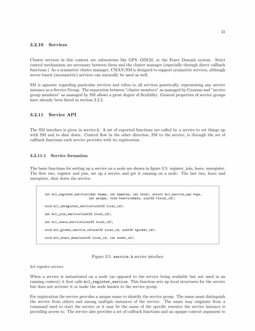
3.2.11.1 Service formation
The basic functions for setting up a service on a node are shown in figure 3.5: register, join, leave, unregister.The first two, register and join, set up a service and get it running on a node. The last two, leave andunregister, shut down the service.
int kcl_register_service(char *name, int namelen, int level, struct kcl_service_ops *ops,
int unique, void *servicedata, uint32 *local_id);
void kcl_unregister_service(uint32 local_id);
int kcl_join_service(uint32 local_id);
int kcl_leave_service(uint32 local_id);
void kcl_global_service_id(uint32 local_id, uint32 *global_id);
void kcl_start_done(uint32 local_id, int event_id);
Figure 3.5: service.h service interface
kcl register service
When a service is instantiated on a node (as opposed to the service being available but not used in anrunning context) it first calls kcl_register_service. This function sets up local structures for the servicebut does not activate it or make the node known to the service group.
For registration the service provides a unique name to identify the service group. The name must distinguishthe service from others and among multiple instances of the service. The name may originate from acommand used to start the service or it may be the name of the specific resource the service instance isproviding access to. The service also provides a set of callback functions and an opaque context argument to

32
be used with the callbacks. The level parameter is defined for each service in service.h. It is chosen accordingto the dependencies between services. Register returns a locally unique ID that is used to reference the localservice group in subsequent calls.
kcl join service
After registration, a service calls kcl_join_service to actually join other cluster members in the givenservice group. The local ID returned from registration is the only parameter. Once this function is called,the first start callback from SM may be received; potentially before the join function returns. There mayalso be an indefinite delay after the join function returns and before the first start callback is received. Thiscould be the case if the cluster is inquorate (as discussed below, services are not enabled/started until thecluster is quorate.)
kcl global service id
Once started, a service may call kcl_global_service_id which returns a globally unique identifier for theservice group. This may be of general use to a service as the unique name used to register may not beconvenient to use in internal functions or communications.
kcl leave service
When a service wishes to shut down on a node, it should leave the service group using kcl_leave_service.Again, the local ID is the only parameter. The service should continue to operate until the leave call returns.Another node may fail during the process of leaving the service group and the service may be stopped andstarted to handle the necessary recovery while waiting for the leave function to return. Before the leavefunction returns a final stop will be the last callback the service receives.
kcl unregister service
Once a service has left the service group, the local structures can be removed by calling kcl_unregister_serviceusing the local ID for the final time.
kcl start done
This function is called by a service to notify SM that it has completed processing a start callback. Theservice only need call this function for the most recent start callback in the event of interrupted recoveries.The event ID parameter is the ID from the start callback to which the kcl_start_done call corresponds.
3.2.11.2 Service control
Cluster management is applied to services through the service callback functions in figure 3.6. A clusterservice is controlled by SM to whatever extent it reacts to the callbacks.
stop
The stop (or suspend) callback tells the service that the group membership is to change. The service instancesuspends operations to the extent that it would produce incorrect results while operating with multiple nodeshaving inconsistent views of the service group membership. The stop callback is not acknowledged by theservice. In general, the service should process the stop synchronously, i.e. before its stop callback functionreturns. The only stop parameter is the service’s context pointer.
The service must be able to handle a stop callback called at any time, even while it’s processing a start

33
struct kcl_service_ops
{int (*stop)(void *servicedata);
int (*start)(void *servicedata, uint32 *nodeids, int count, int event_id, int type);
void (*finish)(void *servicedata, int event_id);
}
Figure 3.6: service.h service control functions
callback or waiting for a finish callback, i.e. a stop can follow another stop, a start or a finish callback.
Stop will be called if a new node joins the service group or if a service group member leaves or fails. Itis guaranteed that stop will be called and will have returned on all service group members before a startcallback is delivered to any group members. Furthermore, it is guaranteed that if a node has failed, allservice groups the node was in have been stopped before any are started.
start
The start (or recover) callback tells the service that the group membership has been changed and providesthe updated member list. The start is delivered to the service on all members of the new service group. Thisincludes new members that have joined and excludes old members that departed. After a node joins a servicegroup, the first start callback is when the service actually begins its operation. The start is asynchronousand it is an appropriate place for a service to do recovery or reconfigure to work with the new member list.When this asynchronous processing of the start is complete, the service must call kcl_service_done (seeabove) to notify SM.
If a service group member fails while the service is processing the start, all remaining group members willreceive a stop callback, regardless if the node has called kcl_service_done or not. The stop effectivelyresets the nodes in the service group and prepares them to receive another start callback. If a node is stillprocessing a start when a stop is delivered, the start should abort. There is no need to call kcl_start_donefor an aborted start.
The event ID parameter is used to distinguish start callbacks, to match a specific finish callback to a specificstart and to match a kcl_start_done with a specific start. The nodeids parameter is an array of countnode ID’s that form the new service group membership. The service is responsible for freeing this memory.
finish
The finish (or resume) callback tells the service that all service group members have completed start pro-cessing and have called kcl_start_done. This is an appropriate time for the service to resume normaloperations as it knows all group members have completed recovery. The event ID parameter is the same asthat used for the start for which the finish applies.
3.2.12 Service Events
Internal SM handling of events.

34
3.3 GDLM
This section details the design, construction and unique advantages provided by GDLM.
3.3.1 Motivation
DLM’s are the de facto standard for high availability distributed locking. Several features of a DLM are thebasis for this and are covered below.
• Availability
DLM offers the highest possible form of availability. There is no number of nodes that can fail, and noselection of nodes that can fail such that the DLM cannot recover and continue to operate.
• Performance
DLM achieves excellent performance by increasing the likelihood of local processing. This performanceadvantage is a simple result of the way DLM’s are designed. Each node ”masters” locks that it creates.When a node is operating on its own files/data, it is master of the corresponding locks and its requestsfor the locks are immediate, requiring no network requests at all.
When multiple nodes are using the same locks and contending for exclusive access to them, the per-formance becomes equivalent to a single lock server with one network request/reply.
Furthermore in the case of contention, the lock manager role of arbitrating among contending requestsis distributed among all nodes in the cluster, so there is no one node relied upon to handle all the work.What can be very high load on a single server can be negligible when distributed across many nodes.The slowdown caused by a heavily loaded lock manager disappears.
• Elimination of Bottlenecks
Bottlenecks in a cluster architecture severely limit both performance and scalability. DLM is designedto eliminate any possible bottleneck. The following briefly describes this.
Bottleneck issues arise quickly when single machines are used as servers. This includes many things:memory, CPU, and network limitations. A DLM, however, distributes lock traffic evenly across allnodes. As more nodes are added, more distribution takes place to reduce any additional load.
Memory bottlenecks In a replicating lock manager, each lock server consumes memory to hold a copyof the entire cluster’s lock state. This can become very large and if running on a GFS node, the lockserver or application can be forced to swap to disk.
A DLM distributes lock state (memory) among all nodes. When DLM locks are mastered locally, nomemory is replicated for them anywhere. For DLM locks mastered remotely, two copies of the lock arekept, one in the memory of the node owning the lock and one on the lock’s master node. In contrast,when using three redundant lock servers, there are four copies of every lock. Therefore, not only isthe DLM’s memory usage evenly distributed across all nodes, but simple calculations show the DLM’stotal usage to be half or less.
CPU bottlenecks A single lock manager must process all requests from all nodes in the cluster. If itis also replicating state, it also has to process replication traffic among all redundant servers. Thelimitations of the CPU can quickly be reached by adding nodes or increasing file system load. With aDLM, just as before, all this processing is balanced across all nodes.
Network bottlenecks A DLM is not a replication system and therefore has far less network traffic whichconsequently increases performance. A replicating lock server quickly becomes impractical becauseof all the replication overhead. Operations become very slow because of heavy network traffic andresponse is only as fast as the slowest server. Each replicating node added makes things worse.

35
• Scalability
Many of the DLM characteristics mentioned above for performance also contribute to scalability. Bot-tlenecks are very often a limitation to scalability which is why symmetric architectures (like GFS andDLM) are designed with extra effort to be symmetric (it’s much simpler and quicker to manage thingsasymmetrically from a single server, the problems are trivial in comparison.)
When all nodes using a DLM split the management tasks there is no one node or subset of nodes thatcan become bogged down due to the addition of too many nodes or too much application load.
• Manageability
The DLM requires no special nodes or special programs that an administrator would need to manage.The DLM maintains the symmetric ”all nodes are equal” concept. This is a fundamentally simplerorganization than other common systems that require various collections of nodes and lock managementprograms to be understood, arranged, started, configured, and managed separately. Additionally, therequirements of a separately managed lock management system are often different than the mainrequirements presented by the real cluster being managed. The intersection of these two differing setsof requirements can be confusing and far more work intensive than the management-free DLM.
• Kernel Implementation
When using DLM there are no user-space components that the kernel subsystems actively rely upon.This can be a big benefit as loads increase and memory becomes scarce.
GFS is a kernel service and farming its functions out to user-space is not only slow but dangerous inlow-memory situations as it can lead to machine deadlocks. DLM being entirely in kernel space canmanage its own memory more directly.
This becomes even more important with the kernel part of CLVM, as it deals with suspended deviceswhich can cause page cache memory to balloon out of control while metadata is updated. As painfullydiscovered, mixing user-space and kernel space in this way can result in complex deadlocks beyond ourcontrol.
3.3.2 Requirements
External interfaces and behaviors:
• Support GFS’s lock request interface.
• Support CLVM’s lock request interface.
• Support standard DLM lock request interface.
• Support arbitrary independent lock spaces.
• Be fully recoverable from all possible failure conditions.
• Be stand-alone (independent of particular usage).
• Be self-configuring (no user input or management required).
• In-progress requests simply block during recovery.
• Requests processed and returned after a failed node’s locks are cleared.

36
3.3.3 Lock Spaces
A lock space in a specific instance of the GDLM service. Any application that would like to take advantageof distributed locking can create a lock space to use. As instances of the application on different nodesrequest the same lock space name, they will operate together in the same lock space. The specific node ID’sof the nodes in the lock space are provided each time the Service Manager starts the lock space following atransition.
Within a lock space, resources an application references itself will exist; none others. The GFS applicationmust, of course, use a separate lock space for each file system because identical resource names will exist inevery file system. e.g ”inode 128”.
So, multiple independent lock spaces allow many applications (different types and different instances of thesame type) to operate at once independently from each other in the cluster.
3.3.3.1 Usage
This interface is used by GDLM applications such as GFS to request new lock spaces and subsequentlyrelease them.
int gdlm_new_lockspace(char *name, int namelen, gdlm_lockspace_t **lockspace, int flags);
int gdlm_release_lockspace(gdlm_lockspace_t *lockspace);
Figure 3.7: gdlm.h lock space usage
gdlm_new_lockspace: The name and namelen parameters naturally refer to the name of the lock spacebeing requested. The lockspace parameter is the lock space context pointer returned to the applicationto be used as the basis for future lock requests. When the function returns, the lock space can be usedimmediately. The flags parameter can enable or disable certain features in a lockspace. Currently, the onlyflag is NOTIMERS which causes requests to not be subject to time-outs after waiting for too long.
gdlm_release_lockspace: The lockspace parameter is the same context pointer as was returned from thelock space creation.
3.3.3.2 Functions: lockspace handling
Within GDLM a lock space is represented by a gd_ls_t structure called the ”lockspace” or ”ls” struct. Itis analogous to a file system’s superblock structure. The following functions deal with lockspace structures.
gd_ls_t *find_lockspace_by_global_id(uint32 id)Searches GDLM’s global list of lockspaces to find one with the specified (global) ID. (A lockspace global IDis defined later.)
gd_ls_t *find_lockspace_by_name(char *name, int namelen)Searches GDLM’s global list of lockspaces to find one with the specified name.
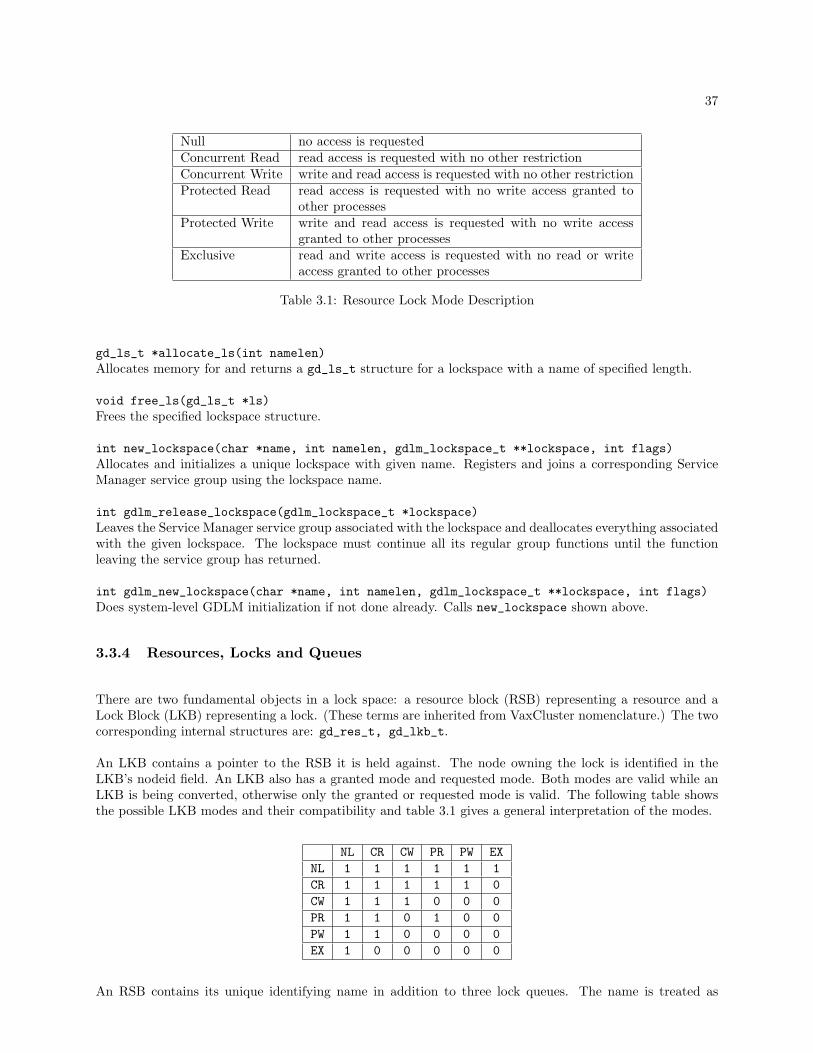
37
Null no access is requestedConcurrent Read read access is requested with no other restrictionConcurrent Write write and read access is requested with no other restrictionProtected Read read access is requested with no write access granted to
other processesProtected Write write and read access is requested with no write access
granted to other processesExclusive read and write access is requested with no read or write
access granted to other processes
Table 3.1: Resource Lock Mode Description
gd_ls_t *allocate_ls(int namelen)Allocates memory for and returns a gd_ls_t structure for a lockspace with a name of specified length.
void free_ls(gd_ls_t *ls)Frees the specified lockspace structure.
int new_lockspace(char *name, int namelen, gdlm_lockspace_t **lockspace, int flags)Allocates and initializes a unique lockspace with given name. Registers and joins a corresponding ServiceManager service group using the lockspace name.
int gdlm_release_lockspace(gdlm_lockspace_t *lockspace)Leaves the Service Manager service group associated with the lockspace and deallocates everything associatedwith the given lockspace. The lockspace must continue all its regular group functions until the functionleaving the service group has returned.
int gdlm_new_lockspace(char *name, int namelen, gdlm_lockspace_t **lockspace, int flags)Does system-level GDLM initialization if not done already. Calls new_lockspace shown above.
3.3.4 Resources, Locks and Queues
There are two fundamental objects in a lock space: a resource block (RSB) representing a resource and aLock Block (LKB) representing a lock. (These terms are inherited from VaxCluster nomenclature.) The twocorresponding internal structures are: gd_res_t, gd_lkb_t.
An LKB contains a pointer to the RSB it is held against. The node owning the lock is identified in theLKB’s nodeid field. An LKB also has a granted mode and requested mode. Both modes are valid while anLKB is being converted, otherwise only the granted or requested mode is valid. The following table showsthe possible LKB modes and their compatibility and table 3.1 gives a general interpretation of the modes.
NL CR CW PR PW EXNL 1 1 1 1 1 1CR 1 1 1 1 1 0CW 1 1 1 0 0 0PR 1 1 0 1 0 0PW 1 1 0 0 0 0EX 1 0 0 0 0 0
An RSB contains its unique identifying name in addition to three lock queues. The name is treated as

38
Name: ANode: 0
Lock QueuesGrantedConvertWaiting
RSB (master) RSB (copy)
Node 1 Node 2
Name: ANode: 1
Lock QueuesGrantedConvertWaiting
Node: 0 Mode: PR(granted)
LKB’s LKB’s
Node: 2 Mode: PR(granted)
Node: 1 Mode: PR(granted)
Node 3
Name: ANode: 1
Lock QueuesGrantedConvertWaiting
LKB’s
Node: 1 Mode: NL(granted)Mode: EX(request)
Node: 3 Mode: NL(granted)Mode: EX(request)
RSB (copy)
Figure 3.8: An RSB’s lock queues
an arbitrary binary sequence of data up to 64 bytes in length; it is not interpreted by GDLM. The threelock queues are: granted, converting and waiting. The granted queue contains currently granted locks onthe resource. The convert queue contains granted locks that are being converted to a requested mode notcompatible with existing granted locks. The wait queue contains ungranted locks with requested modesincompatible with the granted mode of existing granted locks.
An RSB has a master node that is defined in the Resource Directory. The first node to request a lock on anRSB becomes its master. A subsequent node wanting to lock the RSB must first look up the master node IDin the Resource Directory. The locks from all nodes against an RSB are kept in the master RSB’s queues.
A node holding a lock against a remotely mastered RSB also keeps a local copy of the RSB. This is wherethe node keeps a copy of its own locks which officially exist on the master RSB. These copies are used inrecovery if the master node of the RSB fails.
The node ID in the master RSB is set to zero (res_nodeid). The LKB’s owned by the RSB master alsohave node ID’s set to zero, otherwise the node ID identifies the owner. In the case of a non-master RSBcopy, the RSB node ID identifies the master and the LKB’s (all locally owned) also have node ID’s of themaster node. Figure 3.8 gives a simple illustration.
When a lock is requested or converted, its requested mode is compared with the granted mode of all existinglocks on a resource. If it is compatible with them the request is granted immediately and the lock is placedon the RSB granted queue. If the request is not compatible with existing locks, ”blocking AST’s” are sent tothe nodes holding the locks preventing the request from being granted. The request is kept on the convertingor waiting queue.
Whenever a lock is converted to a lower mode or unlocked an attempt is made to grant locks on the convertand wait queues. Demoting a lock to a lower mode will never block.
3.3.4.1 Lock ID’s
When a new LKB is created it is assigned an ID that is used to identify and look up the LKB uniquely inthe lockspace. The LKB can be referenced using its ID without referring to the resource it’s held against.

39
The LKB ID’s are unique only within the context of the local lockspace, i.e. the same LKB ID may refer toa different lock if used on another machines or in another lockspace.
LKB ID’s are 32 bits and have two 16 bit parts. The bottom 16 bits are a random number between 0 andlockidtbl size-1. This random number specifies the bucket for the LKB in the lockspace’s lockidtbl hash table(holds all LKB’s in the lockspace.) The upper 16 bits are a sequentially assigned per-bucket id. (Becausethe 16 bit ID’s per bucket can roll over, a new ID must be checked against the ID of all LKB’s in the bucketto avoid duplication.)
When a lock is held against a remotely mastered RSB, one LKB exists on the node holding the lock andanother LKB representing the same lock exists on the master (the ”master copy” or MSTCPY.) In additionto its own ID, an LKB saves the ID of the matching LKB on the remote node. Both local and remote ID’sare included in messages between nodes, each node using the ID appropriate for its own LKB and simplysaving the other to include in messages. For a local lock held against a locally mastered RSB, the remoteLKB ID is not used.
3.3.4.2 Functions: RSB/LKB structures
int find_or_create_rsb(gd_ls_t *ls, gd_res_t *parent, char *name, int namelen,int create, gd_res_t **rp)
Find an RSB with given name in lockspace’s RSB list and return it. If create is set and the RSB is notfound, create an RSB with the given name and return it. When an RSB is found, increment reference countof the structure. When a parent RSB is provided, both name and parent must match to return an existingRSB.
void release_rsb(gd_res_t *r)Decrement the reference count of the RSB structure. Remove it from the lockspace’s RSB list and deallocateif the reference count becomes zero. Also decrement the reference count of the parent RSB if one exists.Remove the resource directory entry for the RSB if it was removed.
void hold_rsb(gd_res_t *r)Increment the reference count of the RSB structure.
gd_res_t *search_hashchain(osi_list_t *head, gd_res_t *parent, char *name, int namelen)Search the given list for an RSB with given name.
void lkb_add_ordered(osi_list_t *new, osi_list_t *head, int mode)Insert a lock’s list element into the given list in order of mode.
void lkb_enqueue(gd_res_t *r, gd_lkb_t *lkb, int type)Put a lock on the RSB queue specified by type (granted, converting or waiting).
int lkb_dequeue(gd_lkb_t *lkb)Remove a lock from whichever RSB queue it is on.
int lkb_swqueue(gd_res_t *r, gd_lkb_t *lkb, int type)A combination of the previous two operations done atomically, removing the lock from a queue and add itto a new one.
void res_lkb_enqueue(gd_res_t *r, gd_lkb_t *lkb, int type)int res_lkb_dequeue(gd_lkb_t *lkb)int res_lkb_swqueue(gd_res_t *r, gd_lkb_t *lkb, int type)

40
Versions of above that lock the RSB before doing the operation.
gd_lkb_t *create_lkb(gd_ls_t *ls)Allocate a new LKB structure with a new unique ID.
void release_lkb(gd_ls_t *ls, gd_lkb_t *lkb)Remove the given LKB from a lockspace’s LKB hash table (lockidtbl) and free it.
gd_lkb_t *find_lock_by_id(gd_ls_t *ls, gdlm_lkid_t lkid)Look up the LKB with given ID in a lockspace’s LKB hash table (lockidtbl).
3.3.5 Cluster Management
A GDLM lockspace is managed by the Service Manager as a Service Group. Each time SM gives thelockspace the ”start” callback, the group of node ID’s using the lockspace is provided. A lockspace keepstwo lists relative to nodes: ls_nodes and ls_nodes_gone. How and when these lists are updated is coveredin the Recovery section. In general, the ls_nodes list is the current group of nodes in the lockspace. Thels_nodes_gone list is empty except during recovery when it contains nodes that were in the previouslyrunning lockspace but are not in the present lockspace.
Any node using a lockspace is represented by one gd_node_t structure in a global GDLM node list. Thisstructure contains globally constant (not variable or lockspace-specific) properties of a node: its unique nodeID and IP address (both from the cluster manager).
The gd_csb_t structure represents a node in the context of a specific lockspace (Cluster System Block isa term from VaxClusters). It points to the global gd_node_t structure and contains the lockspace-specificproperty gone_event, an event ID discussed later identifying the transition during which the node left thelockspace.
When a lockspace is created and becomes a Service Group, SM returns for it two ID’s. A local ID thatuniquely identifies the lockspace on the node and a global ID that uniquely identifies the lockspace in thecluster. The global ID is the most widely used as it is part of all inter-node GDLM communications.
3.3.5.1 Functions: node information
gd_node_t *allocate_node(void)Allocate a node structure for the global nodes list.
void free_node(gd_node_t *node)Free a node structure.
gd_csb_t *allocate_csb(void)Allocate a CSB structure for a lockspace-specific nodes list.
void free_csb(gd_csb_t *csb)Free a CSB structure.
gd_node_t *search_node(uint32 nodeid)Search the global nodes list for a node structure with specified node ID.
void put_node(gd_node_t *node)

41
Release a reference on a global node structure. When the reference count reaches zero, release it.
int get_node(uint32 nodeid, gd_node_t **ndp)Return an existing node structure with specified node ID, incrementing its reference count or allocate a newnode structure with the specified node ID
int init_new_csb(uint32 nodeid, gd_csb_t **ret_csb)Return a new lockspace-specific CSB structure with specified node ID. The CSB structure points to a globalnode structure for the node in question that contains the node’s global properties.
void release_csb(gd_csb_t *csb)A combination of put_node and free_csb.
uint32 our_nodeid(void)Returns the local node ID. This value is obtained from the cluster manager when the lockspace is firststarted.
void add_ordered_node(gd_ls_t *ls, gd_csb_t *new)Add a CSB structure to a lockspace’s nodes list in order of node ID’s.
int in_nodes_gone(gd_ls_t *ls, uint32 nodeid)Returns TRUE if a node with specified node ID is in a lockspace’s ls_nodes_gone list.
3.3.5.2 Control mechanics
A lockspace is controlled by the Service Manager using the three functions discussed in section 2.2.2. Thefollowing describes how GDLM handles these three callback functions and responds to the cluster eventsthey signal. This is the management of the recovery process. The details of the recovery process itself areleft for a later section.
GDLM has a specific thread (gdlm_recoverd) in charge of processing control input from the Service Manager.This thread also carries out the recovery routines it initiates. This is a global thread that works on behalfof all GDLM lock spaces.
start
When SM calls a lockspace’s gdlm_ls_start function, it means that the lockspace should be enabled to dorequest processing. To do that the lockspace must step through a recovery procedure cooperatively withall nodes in the lockspace. This recovery process is executed asynchronously by the gdlm_recoverd thread.When recovery is done, the lockspace signals to SM that it’s done using the kcl_start_done function.
The gdlm_ls_start function allocates a gd_recover_t structure to record the relevant information forasynchronous processing of the start. The structure saves the list of node ID’s provided by SM that representthe new lockspace membership. The start is unique and sequentially ordered among other control functionsby the ”event ID” provided by SM in each start callback. The event ID is saved in gd_recover_t and inthe lockspace’s ls_last_start field.
stop
When SM calls a lockspace’s gdlm_ls_stop function, it means there is a forthcoming change to the lockspace’smembership and the lockspace should stop normal processing so all lockspace nodes can reconfigure. If thelockspace were to continue processing requests after stop, the lockspace would produce inconsistent results

42
as different nodes may be operating on the basis of differing lockspace membership. Stopping the lockspacewhile all nodes adjust the membership and perform recovery is essential to correct operation.
The gdlm_ls_stop function acquires the lockspace’s in_recovery lock in write mode. This lock is heldin read mode by all processes while processing requests in GDLM (also by gdlm_recvd while processingremote requests.) Acquiring this lock guarantees that when the stop callback returns to SM, no further lockprocessing will occur. The lockspace’s ls_last_stop field is set to the current value of ls_last_start.
finish
When SM calls a lockspace’s gdlm_ls_finish function, it means all nodes that received the prior start havecompleted recovery. The finish callback is accompanied by an event ID that matches the event ID of thestart to which the finish applies. This is saved in the lockspace’s ls_last_finish field.
Callback processing
Once a lockspace is created, the first SM callback it receives is a start. This arrives during or immediatelyafter the return of kcl_join_service (from the SM API).
After a lockspace receives any of the callbacks above (stop, start, finish), gdlm_recoverd looks at the staterecorded from the callback (or callbacks, because the callbacks are processed asynchronously multiple can bereceived between processing of the last) to determine what needs to be done. The possible items recorded bythe callback functions are: flags indicating which callback functions have been received since last checking,new gd_recover_t struct(s) from start, and the ls_last_stop, ls_last_start, ls_last_finish values.
For any lockspace that may have some recovery to handle, the gdlm_recoverd thread calls do_ls_recovery.The first thing done by this function is a call to next_move that collects and combines all the unprocessedcallback state and decides what the next action should be. All possible combinations of callback state canbe reduced to one of the following which next_move will return: DO STOP, DO START, DO FINISH,DO FINISH STOP, DO FINISH START. If the move includes a start, then the relevant gd_recover_tstruct is returned as well.
The next_move function combines SM callbacks to arrive at one of the ”DO” values summarized in thefollowing list. Because the callbacks are processed asynchronously and only a start is acknowledged whencompleted, multiple callbacks can arrive between processing. The event ID’s recorded for each start in thegd_recover_t struct and the values ls_last_stop, ls_last_start, ls_last_finish allow the orderingof the callbacks to be determined.
• DO STOP: A lone stop was received, or a start was received followed by a stop.
• DO START: A lone start was received, or a stop was received followed by a start.
• DO FINISH: A lone finish was received.
• DO FINISH STOP: A finish was received followed by a stop, or a finish was received followed by astart followed by a stop.
• DO FINISH START: A finish was received followed by a stop followed by a start.
do_ls_recovery combines the ”DO” value from next_move with the current lockspace state to deter-mine what recovery functions to call and to assign the next lockspace state. The main recovery functionls_reconfig is called when a DO START or DO FINISH START is returned from next_move.

43
3.3.5.3 Recovery states
A lockspace is moved through the states (ls_state) listed below by do_ls_recovery. The next stateis determined by a combination of the next_move value and the success or failure of ls_reconfig, therecovery function called by do_ls_recovery. Figure 3.9 shows the state transitions. In the figure, START,STOP, FINISH, FINISH STOP, FINISH START represent the next_move values shown above. The ”ok”and ”error” values represent the result of ls_reconfig. The recovery routines in ls_reconfig can returnan error if a lockspace member node fails during recovery.
• INIT: A lockspace is created in this state. Waiting for a start.
• INIT DONE: A lockspace is done with recovery from its first start. Waiting for a finish.
• CLEAR: A lockspace is not in any recovery state having finished the previous recovery successfully.
• WAIT START: A lockspace has received a stop or the recovery for the last start has failed. Waitingfor a start.
• RECONFIG DONE: A lockspace is done with recovery from a start. Waiting for a finish.
3.3.5.4 Functions: recovery management
gd_recover_t *allocate_recover(void)Called from gdlm_ls_start to allocate a gd_recover_t structure with which to save the state associatedwith the start for asynchronous processing. This state includes the list of nodes being started and the eventID of the start.
void free_recover(gd_recover_t *gr)Frees a gd_recover_t structure.
int gdlm_ls_stop(void *servicedata)GDLM’s stop function called by the Service Manager.
int gdlm_ls_start(void *servicedata, uint32 *nodeids, int count, int event_id, int type)GDLM’s start function called by the Service Manager.
void gdlm_ls_finish(void *servicedata, int event_id)GDLM’s finish function called by the Service Manager.
void enable_locking(gd_ls_t *ls, int event_id)Enable locking based on the completion of recovery for the event with specified ID. Locking will not beenabled if a more recent stop event has arrived. Locking is enabled by setting the LS RUN lockspace bitand unlocking the in_recovery write lock.
int ls_reconfig(gd_ls_t *ls, gd_recover_t *gr)Called when a lockspace is started to do recovery.
int ls_first_start(gd_ls_t *ls, gd_recover_t *gr)Called in place of ls_reconfig to do first-time recovery (which is reduced) the first time a lockspace isstarted.

44
CLEAR
WAITSTART
RECONFIGDONE
INITDONEINIT
(START & ok)
STOP, FINISH_STOP, (START & error),(FINISH_START & error)
STOP,(START & error)
(START & ok),(FINISH_START & ok)
STOP, (START & error)
(START & ok)
FINISH
FINISH(START & ok),
(FINISH_START & ok)
STOP, FINISH_STOP, (START & error),(FINISH_START & error)
(START & ok)
STOP,(START & error)
Figure 3.9: Lockspace recovery states
45
void clear_finished_nodes(gd_ls_t *ls, int finish_event)Called when a finish is received to remove node structures from the ls_nodes_gone list of nodes for whichrecovery was conducted.
int next_move(gd_ls_t *ls, gd_recover_t **gr_out, int *finish_out)Combines the state recorded from Service Manager callback functions to determine what recovery action totake next.
void do_ls_recovery(gd_ls_t *ls)Step through the lockspace recovery states based on input from next_move and the success or failure ofrecovery routines (ls_reconfig) that it calls.
gd_ls_t *get_work(int clear)Called by the gdlm_recoverd thread to get a lockspace for which recovery is necessary. A lockspace ismarked as needing recovery attention with the WORK flag set by ctrld_kick.
int gdlm_ctrld(void *arg)The top-level gdlm_recoverd function that processes recovery for lockspaces.
void ctrld_kick(gd_ls_t *ls)Marks a lockspace as needing recovery attention. Called by Service Manager callback functions on thelockspaces referenced.
3.3.5.5 Cluster information
In addition to being controlled by the cluster manager in response to cluster transitions, GDLM needs toquery the cluster manager for some basic information. First, GDLM needs to know the node ID of the nodeit’s running on, i.e. its own node ID. Second, GDLM needs to look up the IP address of another node ID.The Service Manager provides lock space membership in terms of node ID’s. GDLM needs to communicatewith these nodes and therefore also needs IP addresses. There are basic exported CMAN functions thatprovide this information along with a variety of other information that is unused.
3.3.6 Lock Requests
This section discusses the primary function of GDLM, the processing of asynchronous lock requests. Itbegins with the exported lock request API and continues with details of the internal request processing.
3.3.6.1 Usage
Figure 3.10 shows the GDLM locking interface comprised of the two functions gdlm_lock and gdlm_unlock.Before a description of their use in an application, one GDLM structure used in the interface, gdlm_lksb_t,should be described.
Shown in figure 3.11, the Lock Status Block (LKSB, another term from VaxCluster’s DLM) is a structureused for both input and output parameters. Every lock request must be accompanied by an LKSB structureallocated by the application.
The LKSB provides a place for GDLM to return results of a request. The results are ready and can be readby the application once the asynchronous completion callback (AST) is called. There can be multiple parts
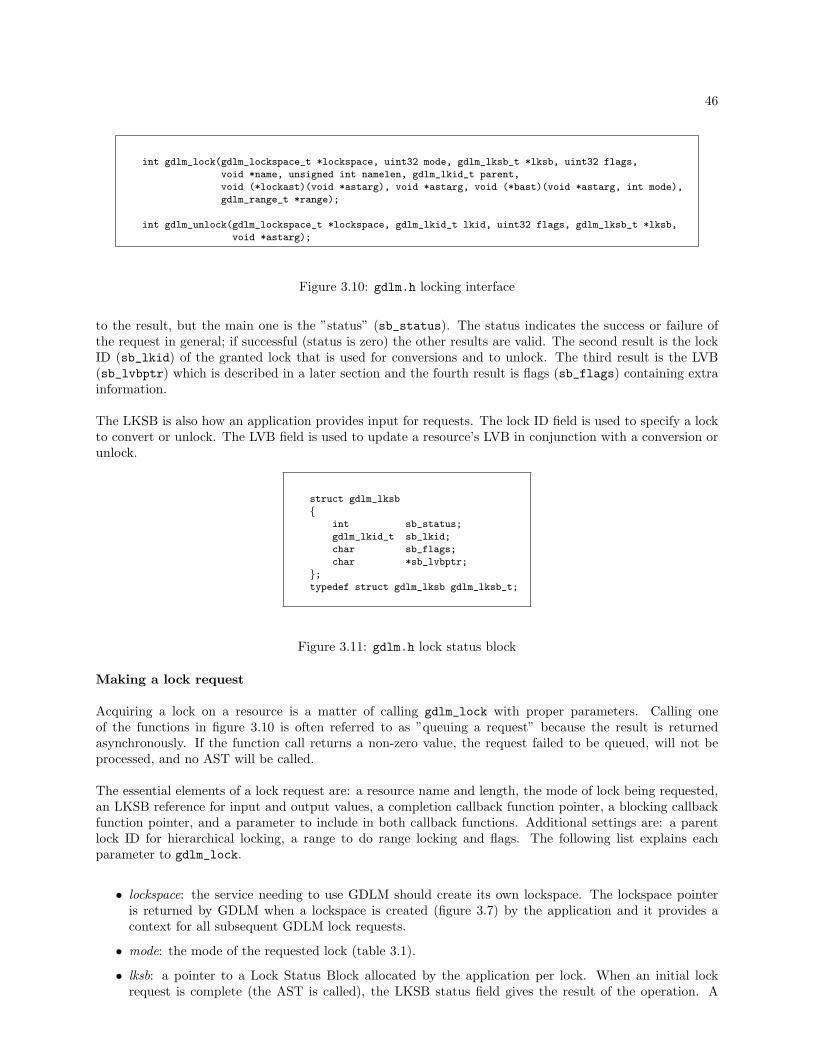
46
int gdlm_lock(gdlm_lockspace_t *lockspace, uint32 mode, gdlm_lksb_t *lksb, uint32 flags,
void *name, unsigned int namelen, gdlm_lkid_t parent,
void (*lockast)(void *astarg), void *astarg, void (*bast)(void *astarg, int mode),
gdlm_range_t *range);
int gdlm_unlock(gdlm_lockspace_t *lockspace, gdlm_lkid_t lkid, uint32 flags, gdlm_lksb_t *lksb,
void *astarg);
Figure 3.10: gdlm.h locking interface
to the result, but the main one is the ”status” (sb_status). The status indicates the success or failure ofthe request in general; if successful (status is zero) the other results are valid. The second result is the lockID (sb_lkid) of the granted lock that is used for conversions and to unlock. The third result is the LVB(sb_lvbptr) which is described in a later section and the fourth result is flags (sb_flags) containing extrainformation.
The LKSB is also how an application provides input for requests. The lock ID field is used to specify a lockto convert or unlock. The LVB field is used to update a resource’s LVB in conjunction with a conversion orunlock.
struct gdlm_lksb
{int sb_status;
gdlm_lkid_t sb_lkid;
char sb_flags;
char *sb_lvbptr;
};typedef struct gdlm_lksb gdlm_lksb_t;
Figure 3.11: gdlm.h lock status block
Making a lock request
Acquiring a lock on a resource is a matter of calling gdlm_lock with proper parameters. Calling oneof the functions in figure 3.10 is often referred to as ”queuing a request” because the result is returnedasynchronously. If the function call returns a non-zero value, the request failed to be queued, will not beprocessed, and no AST will be called.
The essential elements of a lock request are: a resource name and length, the mode of lock being requested,an LKSB reference for input and output values, a completion callback function pointer, a blocking callbackfunction pointer, and a parameter to include in both callback functions. Additional settings are: a parentlock ID for hierarchical locking, a range to do range locking and flags. The following list explains eachparameter to gdlm_lock.
• lockspace: the service needing to use GDLM should create its own lockspace. The lockspace pointeris returned by GDLM when a lockspace is created (figure 3.7) by the application and it provides acontext for all subsequent GDLM lock requests.
• mode: the mode of the requested lock (table 3.1).
• lksb: a pointer to a Lock Status Block allocated by the application per lock. When an initial lockrequest is complete (the AST is called), the LKSB status field gives the result of the operation. A

47
status of zero means the requested lock has been granted. A status of -EAGAIN means the NOQUEUEflag was used and the requested lock could not be granted immediately. Other errors mean there wassome kind of non-standard internal error.
If the request was successful, the LKSB lock ID field was filled in by GDLM with the granted lock’sunique ID (per-node). This ID must be used as input in the same field for subsequent conversions orunlocking of the lock.
• flags: NOQUEUE means the request should not be queued if the lock cannot be granted immediately.If this is the case, the request should return -EAGAIN in the LKSB status field. CONVERT must beset if the request is a conversion of an existing lock. QUECVT forces a conversion to the back of theconvert queue. All other conversion requests ahead of it must be granted before it can, enforcing aFIFO ordering on the convert queue. This can be used to avoid indefinite postponement and is onlyapplicable when converting a lock to a more restrictive mode. CONVDEADLK allows GDLM to demotethe granted state of a converting lock to avoid conversion deadlock.
• name: the name of the resource being locked. Treated as an arbitrary array of binary data.
• namelen: the name length in bytes.
• parent: the parent lock ID used for hierarchical locking. (See section on hierarchical locking.)
• lockast: the function GDLM should call when the request completes.
• astarg: the parameter GDLM should include in callback functions related to the lock being requested.Generally used by the application to identify the specific lock to which the callback pertains.
• bast: the function GDLM should call when the lock being requested blocks another request. Using thisfunction’s mode parameter, GDLM specifies the mode that the blocked request has requested.
• range: a structure specifying a range with start and end values. (See section on range locking.)
If AST routines or the AST parameter are provided in conversion requests, they overwrite the previously setvalues. AST routines should avoid blocking; they may submit other GDLM requests.
Making an unlock request
To release a lock from a resource the gdlm_unlock function is used. The following list describes the functionparameters.
• lockspace: see previous description
• lkid: the lock ID of the lock being released. In gdlm_lock this value is specified in the LKSB.
• flags: CANCEL means that any outstanding request for the specified lock should be canceled. If therequest was a conversion, the lock will be returned to its previously granted state. The LKSB statusreturned for the canceled request will be -GDLM ECANCEL.
• lksb: the result of the unlock is returned in the status field. A status of -GDLM EUNLOCK indicatessuccess. An unlock should never fail.
• astarg: the parameter GDLM should include in the completion callback function. The AST functionused in the prior gdlm_lock call is called by GDLM when the unlock is complete.
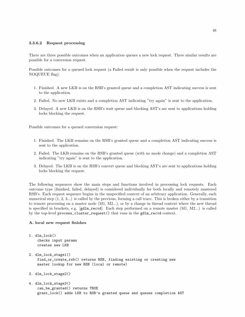
48
3.3.6.2 Request processing
There are three possible outcomes when an application queues a new lock request. Three similar results arepossible for a conversion request.
Possible outcomes for a queued lock request (a Failed result is only possible when the request includes theNOQUEUE flag):
1. Finished. A new LKB is on the RSB’s granted queue and a completion AST indicating success is sentto the application.
2. Failed. No new LKB exists and a completion AST indicating ”try again” is sent to the application.
3. Delayed. A new LKB is on the RSB’s wait queue and blocking AST’s are sent to applications holdinglocks blocking the request.
Possible outcomes for a queued conversion request:
1. Finished. The LKB remains on the RSB’s granted queue and a completion AST indicating success issent to the application.
2. Failed. The LKB remains on the RSB’s granted queue (with no mode change) and a completion ASTindicating ”try again” is sent to the application.
3. Delayed. The LKB is on the RSB’s convert queue and blocking AST’s are sent to applications holdinglocks blocking the request.
The following sequences show the main steps and functions involved in processing lock requests. Eachoutcome type (finished, failed, delayed) is considered individually for both locally and remotely masteredRSB’s. Each request sequence begins in the unspecified context of an arbitrary application. Generally, eachnumerical step (1, 2, 3...) is called by the previous, forming a call trace. This is broken either by a transitionto remote processing on a master node (M1, M2...), or by a change in thread context where the new threadis specified in brackets, e.g. [gdlm_recvd]. Each step performed on a remote master (M1, M2...) is calledby the top-level process_cluster_request() that runs in the gdlm_recvd context.
A. local new request finishes
1. dlm_lock()checks input paramscreates new LKB
2. dlm_lock_stage1()find_or_create_rsb() returns RSB, finding existing or creating newmaster lookup for new RSB (local or remote)
3. dlm_lock_stage2()
4. dlm_lock_stage3()can_be_granted() returns TRUEgrant_lock() adds LKB to RSB’s granted queue and queues completion AST
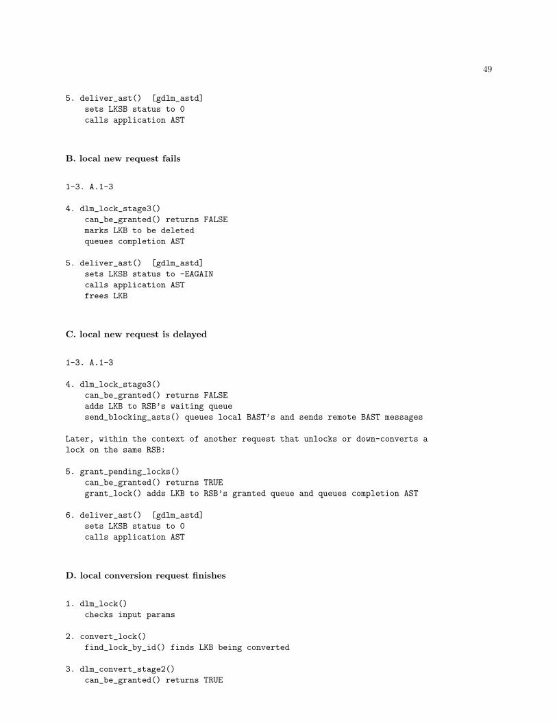
49
5. deliver_ast() [gdlm_astd]sets LKSB status to 0calls application AST
B. local new request fails
1-3. A.1-3
4. dlm_lock_stage3()can_be_granted() returns FALSEmarks LKB to be deletedqueues completion AST
5. deliver_ast() [gdlm_astd]sets LKSB status to -EAGAINcalls application ASTfrees LKB
C. local new request is delayed
1-3. A.1-3
4. dlm_lock_stage3()can_be_granted() returns FALSEadds LKB to RSB’s waiting queuesend_blocking_asts() queues local BAST’s and sends remote BAST messages
Later, within the context of another request that unlocks or down-converts alock on the same RSB:
5. grant_pending_locks()can_be_granted() returns TRUEgrant_lock() adds LKB to RSB’s granted queue and queues completion AST
6. deliver_ast() [gdlm_astd]sets LKSB status to 0calls application AST
D. local conversion request finishes
1. dlm_lock()checks input params
2. convert_lock()find_lock_by_id() finds LKB being converted
3. dlm_convert_stage2()can_be_granted() returns TRUE

50
grant_lock() leaves LKB on RSB’s granted queue and queues completion ASTgrant_pending_locks() grants unblocked LKB’s
4. deliver_ast() [gdlm_astd]sets LKSB status to 0calls application AST
E. local conversion request fails
1-2. D.1-2
3. dlm_convert_stage2()can_be_granted() returns FALSEadds LKB back to RSB’s granted queue with original modequeues completion AST
4. deliver_ast() [gdlm_astd]sets LKSB status to -EAGAINcalls application AST
F. local conversion request is delayed
1-2. D.1-2
3. dlm_convert_stage2()can_be_granted() returns FALSEadds LKB to RSB’s convert queuesend_blocking_asts() queues local BAST’s and sends remote BAST messages
Later, within the context of another request that unlocks or down-converts alock on the same RSB:
4. grant_pending_locks()can_be_granted() returns TRUEgrant_lock() adds LKB to RSB’s granted queue and queues completion AST
5. deliver_ast() [gdlm_astd]sets LKSB status to 0calls application AST
G. remote new request finishes
1. dlm_lock()checks input paramscreates new LKB
2. dlm_lock_stage1()find_or_create_rsb() returns local RSB, finding existing or creating new
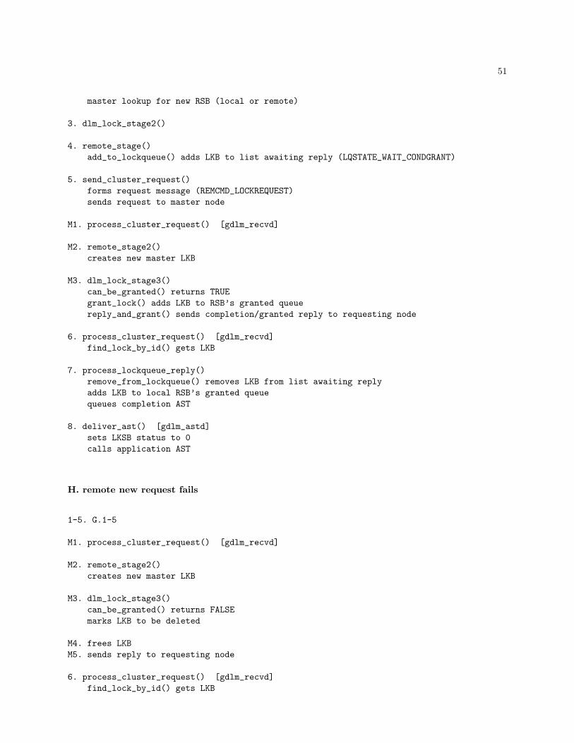
51
master lookup for new RSB (local or remote)
3. dlm_lock_stage2()
4. remote_stage()add_to_lockqueue() adds LKB to list awaiting reply (LQSTATE_WAIT_CONDGRANT)
5. send_cluster_request()forms request message (REMCMD_LOCKREQUEST)sends request to master node
M1. process_cluster_request() [gdlm_recvd]
M2. remote_stage2()creates new master LKB
M3. dlm_lock_stage3()can_be_granted() returns TRUEgrant_lock() adds LKB to RSB’s granted queuereply_and_grant() sends completion/granted reply to requesting node
6. process_cluster_request() [gdlm_recvd]find_lock_by_id() gets LKB
7. process_lockqueue_reply()remove_from_lockqueue() removes LKB from list awaiting replyadds LKB to local RSB’s granted queuequeues completion AST
8. deliver_ast() [gdlm_astd]sets LKSB status to 0calls application AST
H. remote new request fails
1-5. G.1-5
M1. process_cluster_request() [gdlm_recvd]
M2. remote_stage2()creates new master LKB
M3. dlm_lock_stage3()can_be_granted() returns FALSEmarks LKB to be deleted
M4. frees LKBM5. sends reply to requesting node
6. process_cluster_request() [gdlm_recvd]find_lock_by_id() gets LKB

52
7. process_lockqueue_reply()remove_from_lockqueue() removes LKB from list awaiting replymarks LKB to be deletedqueues completion AST
8. deliver_ast() [gdlm_astd]sets LKSB status to -EAGAINcalls application ASTfrees LKB
I. remote new request is delayed
1-5. G.1-5
M1. process_cluster_request() [gdlm_recvd]
M2. remote_stage2()creates new master LKB
M3. dlm_lock_stage3()can_be_granted() returns FALSEadds LKB to RSB’s waiting queuesend_blocking_asts() queues local BAST’s and sends remote BAST messages
M4. sends reply to requesting node
6. process_cluster_request() [gdlm_recvd]find_lock_by_id() gets LKB
7. process_lockqueue_reply()remove_from_lockqueue() removes LKB from list awaiting replyadds LKB to local RSB’s waiting queue
Later, within the context of another request that unlocks or down-converts alock on the same RSB:
M5. grant_pending_locks()can_be_granted() returns TRUEgrant_lock() adds LKB to RSB’s granted queueremote_grant() sends granted message to requesting node (REMCMD_LOCKGRANT)
8. process_cluster_request() [gdlm_recvd]find_lock_by_id() gets LKBadds LKB to local RSB’s granted queuequeues completion AST
9. deliver_ast() [gdlm_astd]sets LKSB status to 0calls application AST
J. remote conversion request finishes
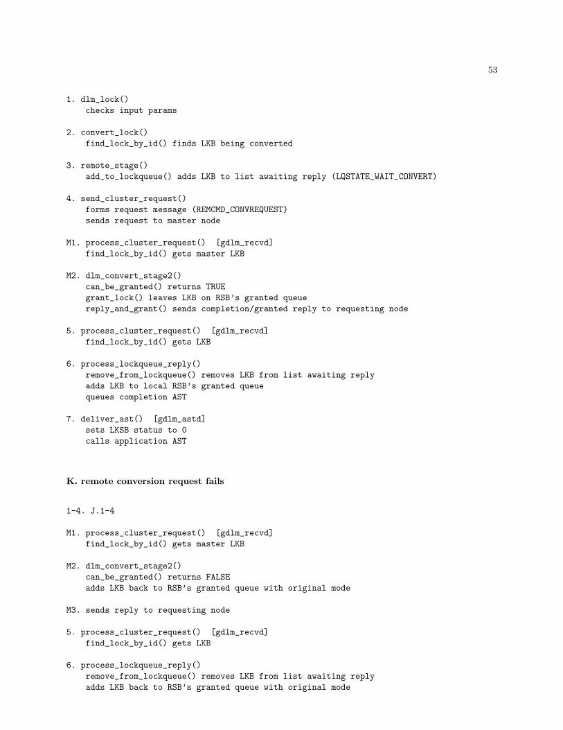
53
1. dlm_lock()checks input params
2. convert_lock()find_lock_by_id() finds LKB being converted
3. remote_stage()add_to_lockqueue() adds LKB to list awaiting reply (LQSTATE_WAIT_CONVERT)
4. send_cluster_request()forms request message (REMCMD_CONVREQUEST)sends request to master node
M1. process_cluster_request() [gdlm_recvd]find_lock_by_id() gets master LKB
M2. dlm_convert_stage2()can_be_granted() returns TRUEgrant_lock() leaves LKB on RSB’s granted queuereply_and_grant() sends completion/granted reply to requesting node
5. process_cluster_request() [gdlm_recvd]find_lock_by_id() gets LKB
6. process_lockqueue_reply()remove_from_lockqueue() removes LKB from list awaiting replyadds LKB to local RSB’s granted queuequeues completion AST
7. deliver_ast() [gdlm_astd]sets LKSB status to 0calls application AST
K. remote conversion request fails
1-4. J.1-4
M1. process_cluster_request() [gdlm_recvd]find_lock_by_id() gets master LKB
M2. dlm_convert_stage2()can_be_granted() returns FALSEadds LKB back to RSB’s granted queue with original mode
M3. sends reply to requesting node
5. process_cluster_request() [gdlm_recvd]find_lock_by_id() gets LKB
6. process_lockqueue_reply()remove_from_lockqueue() removes LKB from list awaiting replyadds LKB back to RSB’s granted queue with original mode

54
queues completion AST
7. deliver_ast() [gdlm_astd]sets LKSB status to -EAGAINcalls application AST
L. remote conversion request is delayed
1-4. J.1-4
M1. process_cluster_request() [gdlm_recvd]find_lock_by_id() gets master LKB
M2. dlm_convert_stage2()can_be_granted() returns FALSEadds LKB to RSB’s convert queue
M3. sends reply to requesting node
5. process_cluster_request() [gdlm_recvd]find_lock_by_id() gets LKB
6. process_lockqueue_reply()remove_from_lockqueue() removes LKB from list awaiting replyadds LKB to local RSB’s convert queue
Later, within the context of another request that unlocks or down-converts alock on the same RSB:
M4. grant_pending_locks()can_be_granted() returns TRUEgrant_lock() adds LKB to RSB’s granted queueremote_grant() sends granted message to requesting node (REMCMD_LOCKGRANT)
7. process_cluster_request() [gdlm_recvd]find_lock_by_id() gets LKBadds LKB to local RSB’s granted queuequeues completion AST
8. deliver_ast() [gdlm_astd]sets LKSB status to 0calls application AST
3.3.6.3 Unlock request processing
Unlock requests are asynchronous and are processed much like conversion requests. Unlock requests can onlysucceed, however; they will never fail or be delayed in the sense of new or conversion requests. The followingtwo sequences show the steps in processing unlock requests for local and remotely mastered locks.
A. local unlock request

55
1. dlm_unlock()checks input params
2. dlm_unlock_stage2()removes LKB from RSB granted queuemarks LKB to be deletedqueues completion AST
3. deliver_ast() [gdlm_astd]sets LKSB status to -GDLM_EUNLOCKcalls application AST
B. remote unlock request
1. dlm_unlock()checks input params
2. remote_stage()add_to_lockqueue() adds LKB to list awaiting reply (LQSTATE_WAIT_UNLOCK)
3. send_cluster_request()forms request message (REMCMD_UNLOCKREQUEST)sends request to master node
M1. process_cluster_request() [gdlm_recvd]find_lock_by_id() gets master LKB
M2. dlm_unlock_stage2()removes LKB from RSB granted queuefrees LKB
M3. sends reply to requesting node
4. process_cluster_request() [gdlm_recvd]find_lock_by_id() gets LKB
5. process_lockqueue_reply()remove_from_lockqueue() removes LKB from list awaiting replyremoves LKB from local RSB’s granted queuequeues completion AST
6. deliver_ast() [gdlm_astd]sets LKSB status to -GDLM_EUNLOCKcalls application AST
3.3.6.4 Canceling a request
An outstanding request can be canceled using the gdlm_unlock with the CANCEL flag. The gdlm_unlockreturn value or the completion AST status will be -EINVAL if the lock is granted before the request canbe canceled. When successful, the cancel will cause the lock to be returned to its previously granted state(or deleted in the case of an initial request being canceled) and the completion AST status will be set to-GDLM ECANCEL.

56
3.3.6.5 AST handling
The gdlm_astd thread is dedicated to calling completion and blocking AST functions in all lock spaces.Each LKB saves AST function pointers (and an argument pointer) that were provided in the request for thelock represented by the LKB. When a completion or blocking AST for the lock is needed, the LKB is placedon a global list of LKB’s requiring ASTs to be called (ast_queue).
While LKB’s exist on the ast_queue, the thread removes one at a time in the process_asts function. Thedeliver_ast function is then used to call either the completion or blocking AST for the LKB (it is calledtwice, once for each, if both types are needed). These routines must be aware that an LKB can be placedback on the ast_queue at any time once it has been removed for either type of AST. Locks must not beheld while calling the application AST function because it may call back into GDLM with another requestthat can potentially queue another AST for the same LKB.
After delivering an AST, the gdlm_astd thread will free the LKB if the AST delivery was the last step indeleting it. This can also result in the associated RSB being freed.
Within the locking routines, the queue_ast function is called with an LKB and AST type to cause an ASTto be delivered. In the previous request processing sequences, this was referred to as ”queues completionAST” or ”queues local BAST’s”. This will add the LKB to the local ast_queue if the LKB is local. Ifthe LKB is remote, the function sends a message that will cause the remote node to add the LKB to itsast_queue. Remote completion ASTs are queued on the remote node implicitly with a message to a remotenode indicating that a request has been granted.
3.3.7 Resource Directory
A lock space’s Resource Directory (RD) stores the mapping of resource names to master node ID’s. RDlookup requests provide a resource name as input and the reply contains the node ID of the master. If therequested RSB name is not in the RD, a new RD entry is created with the requested name and the masternode set to the requesting node.
Every node in the lockspace operates a fraction of the RD. A hash function common to all nodes staticallytranslates a resource name to a RD node ID. The RD segment on this node identifies the master node forthe resource. So, an RSB has two associated node ID’s. The first is the node holding the RD mapping andthe second is the master node. These two may or may not be the same; the former is static and the laterdynamic.
An RD entry is represented by a gd_resdata_t structure. This structure contains a resource name and thenode ID of the RSB’s master. Each node keeps its RD entries on a hash table (ls_resdir_hash). The lower16 bits of a resource name’s hash value are used for this hash table while the upper 16 bits of the hash valueare used to determine the RD node.
When a node requests a lock on an RSB that does not exist locally, a RD lookup must take place to determinethe RSB’s master. The master ID is saved in the RSB so further lock requests on the RSB do not requirean RD lookup. This lookup step, mentioned in the previous section simply as ”master lookup for new RSB”may be a local or remote operation. It will most likely be remote (more likely with more nodes in the lockspace) because the RD hash function evenly distributes the RD entries among nodes.
In the best case for a new lock request, no network requests are needed: the the RD lookup is local and themaster becomes local. In the worst case, two network requests are needed: the RD lookup is remote and amaster exists that is remote.

57
The following steps are involved in looking up a resource master. It begins in dlm_lock_stage1() afterget_directory_nodeid() returns a remote node ID; it is an expansion of the step in the previous sectionlabeled ”master lookup for new RSB”.
1. remote_stage()add_to_lockqueue() adds LKB to list awaiting reply (LQSTATE_WAIT_RSB)
2. send_cluster_request()forms request message (REMCMD_LOOKUP)sends request to node
RD1. process_cluster_request() [gdlm_recvd]
RD2. get_resdata()finds existing entry for given name or creates new entry
RD3. sends reply to requesting node
3. process_cluster_request() [gdlm_recvd]find_lock_by_id() gets LKB
4. process_lockqueue_reply()remove_from_lockqueue() removes LKB from list awaiting replysets RSB master node ID
3.3.7.1 Removing entries
When a master RSB is deleted its resource directory entry is also deleted. After unlinking the RSB fromthe local RSB list, the master node sends a removal message to the resource’s directory node (or removesit directly if the directory node is also be the master node.) RD removal messages are asynchronous andunacknowledged which can lead to a variety of special cases described in the following.
Case 1Problem: An RSB is deleted on master node M and an RD removal message is sent to node D. Node Lsends a RD lookup to node D for same resource. Node D receives the lookup before the removal and amessage specifying node M as master is returned to node L even though node M no longer has any record ofthe resource. Case 3 can arise here if a lookup now originates on node M. Case 2 occurs when the removalmessage from node L is processed by node D.
Solution: Node L sends its lock request to node M. Node M recreates the RSB and becomes the master forthe resource again. When node M processes the lock request from L in remote_stage2() it passes create=1into find_or_create_rsb() to permit creation of a new RSB.
Case 2Problem: In the previous example, the removal message processed on node D must not remove the entrybecause it is now in use again, having just been sent to node L. The removal message is invalid havingbeen meant for the previous ”version” of the specific RD entry. The removal message must be recognized asinvalid and ignored by node D.
Solution: A counter is kept on each RD entry that is incremented for each lookup. The counter is returnedwith the lookup reply and is then included with the lock request when sent to the master node. The masternode keeps track of the latest counter value for the RSB. When the master sends a removal message to the

58
directory node, it includes the latest counter value it has observed. Ordinarily, this matches the countervalue in the RD and the entry is removed.
In the case where a lookup has occurred for the RD entry just before the removal message is received, as inthe example above, the RD entry will have a larger counter value than the removal request. If this is thecase the removal request is ignored.
Case 3Problem: In the first example, a new request on node M could occur after M has sent the removal request,and after L’s RD lookup. A lookup from M will be sent to node D for the resource. Node D will replyindicating that M itself is the master.
Solution: Node M should accept that the RD may indicate it is the master of a resource it is looking up.
Handling removal requests during recovery is simple. Because the resource directory is rebuilt during recoveryfrom existing RSB’s, removal requests for deleted RSB’s can be discarded. Also, lookup counters in all RDentries and in all RSB’s are reset to one to avoid the large task of finding correct counter values (there areno removal races to contend with during recovery so resetting all counters to one disrupts nothing.)
3.3.7.2 Functions: resource directory
uint32 name_to_directory_nodeid(gd_ls_t *ls, char *name, int length)Returns the node ID of the directory node for the named resource.
uint32 get_directory_nodeid(gd_res_t *rsb)Calls the previous function with the name of the RSB.
uint32 rd_hash(gd_ls_t *ls, char *name, int len)Using the given name, compute a scaled hash value for the resource directory.
void add_resdata_to_hash(gd_ls_t *ls, gd_resdata_t *rd)Add a new resource data struct to the resource directory hash table.
gd_resdata_t *search_rdbucket(gd_ls_t *ls, char *name, int namelen, uint32 bucket)Search a hash table list for a resource data struct matching given name.
void remove_resdata(gd_ls_t *ls, uint32 nodeid, char *name, int namelen, uint8 sequence)Remove resource data struct for given name from resource directory hash table.
int get_resdata(gd_ls_t *ls, uint32 nodeid, char *name, int namelen, gd_resdata_t **rdp, int recovery)Find and return a resource data structure for given name, creating a new one if none is found.
3.3.8 Hierarchical Locking
Hierarchical locks allow structured or optimized forms of locking by applications. In particular, resourcesrelated in a tree structure are often a good candidate for hierarchical locks.
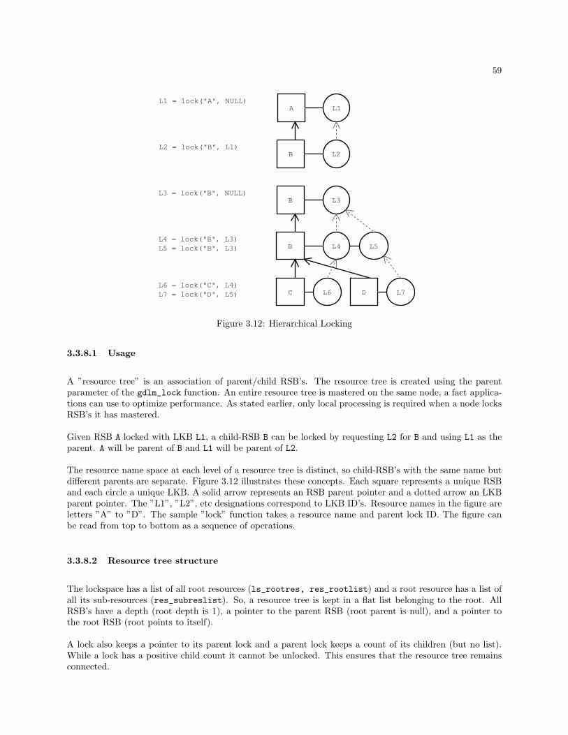
59
A
B
L1
L2
B
B
L3
L4 L5
L1 = lock("A", NULL)
L2 = lock("B", L1)
L3 = lock("B", NULL)
L4 = lock("B", L3) L5 = lock("B", L3)
L6CL6 = lock("C", L4) L7 = lock("D", L5) D L7
Figure 3.12: Hierarchical Locking
3.3.8.1 Usage
A ”resource tree” is an association of parent/child RSB’s. The resource tree is created using the parentparameter of the gdlm_lock function. An entire resource tree is mastered on the same node, a fact applica-tions can use to optimize performance. As stated earlier, only local processing is required when a node locksRSB’s it has mastered.
Given RSB A locked with LKB L1, a child-RSB B can be locked by requesting L2 for B and using L1 as theparent. A will be parent of B and L1 will be parent of L2.
The resource name space at each level of a resource tree is distinct, so child-RSB’s with the same name butdifferent parents are separate. Figure 3.12 illustrates these concepts. Each square represents a unique RSBand each circle a unique LKB. A solid arrow represents an RSB parent pointer and a dotted arrow an LKBparent pointer. The ”L1”, ”L2”, etc designations correspond to LKB ID’s. Resource names in the figure areletters ”A” to ”D”. The sample ”lock” function takes a resource name and parent lock ID. The figure canbe read from top to bottom as a sequence of operations.
3.3.8.2 Resource tree structure
The lockspace has a list of all root resources (ls_rootres, res_rootlist) and a root resource has a list ofall its sub-resources (res_subreslist). So, a resource tree is kept in a flat list belonging to the root. AllRSB’s have a depth (root depth is 1), a pointer to the parent RSB (root parent is null), and a pointer tothe root RSB (root points to itself).
A lock also keeps a pointer to its parent lock and a parent lock keeps a count of its children (but no list).While a lock has a positive child count it cannot be unlocked. This ensures that the resource tree remainsconnected.
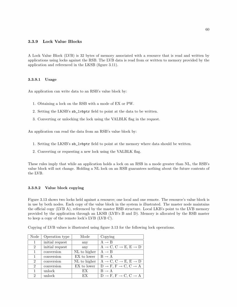
60
3.3.9 Lock Value Blocks
A Lock Value Block (LVB) is 32 bytes of memory associated with a resource that is read and written byapplications using locks against the RSB. The LVB data is read from or written to memory provided by theapplication and referenced in the LKSB (figure 3.11).
3.3.9.1 Usage
An application can write data to an RSB’s value block by:
1. Obtaining a lock on the RSB with a mode of EX or PW.
2. Setting the LKSB’s sb_lvbptr field to point at the data to be written.
3. Converting or unlocking the lock using the VALBLK flag in the request.
An application can read the data from an RSB’s value block by:
1. Setting the LKSB’s sb_lvbptr field to point at the memory where data should be written.
2. Converting or requesting a new lock using the VALBLK flag.
These rules imply that while an application holds a lock on an RSB in a mode greater than NL, the RSB’svalue block will not change. Holding a NL lock on an RSB guarantees nothing about the future contents ofthe LVB.
3.3.9.2 Value block copying
Figure 3.13 shows two locks held against a resource; one local and one remote. The resource’s value block isin use by both nodes. Each copy of the value block in the system is illustrated. The master node maintainsthe official copy (LVB A), referenced by the master RSB structure. Local LKB’s point to the LVB memoryprovided by the application through an LKSB (LVB’s B and D). Memory is allocated by the RSB masterto keep a copy of the remote lock’s LVB (LVB C).
Copying of LVB values is illustrated using figure 3.13 for the following lock operations.
Node Operation type Mode Copying1 initial request any A → B2 initial request any A → C, C → E, E → D1 conversion NL to higher A → B1 conversion EX to lower B → A2 conversion NL to higher A → C, C → E, E → D2 conversion EX to lower D → F, F → C, C → A1 unlock EX B → A2 unlock EX D → F, F → C, C → A

61
RSB(master)
Name: XNode: 0
Node 1
LKB
Node: 0
Node 2
RSB(copy)
Name: XNode: 1
LKB(copy)Node: 2
LKB
Node: 1
LVBB
LVBD
LVBC
LVBA
ApplicationLKSB
ApplicationLKSB
networkmessages
LVBE
LVBF
Figure 3.13: Lock Value Blocks
3.3.10 Lock Ranges
The range parameter in the lock request function allows a lock to be requested against part of a resourceinstead of the whole thing. This can be used to support things such as POSIX/fcntl() locking.
3.3.10.1 Usage
There are some simple rules governing the behavior of range locking:
• A lock request can specify a range (start and end values) by passing a pointer to a gdlm_range_tstructure (figure 3.14.)
• The maximum range (0 - FFFFFFFF.FFFFFFFF) is used if no range is specified in a request.
• A conversion request can be used to change a lock’s mode, range, or both.
• Two locks on a resource are incompatible if their modes are incompatible and their ranges overlap.
• Unlock requests operate as usual and do not specify ranges; a lock is released with whatever range itpresently has.
• Blocking callbacks do not currently include the range specified by a blocked request. This will be addedif it becomes useful.
3.3.11 Deadlock
GDLM does not search for possible deadlocks in a lockspace. There are two features that can help anapplication, however. The first is request timers. After waiting ungranted for a configurable period of time,

62
struct gdlm_range
{uint64 ra_start;
uint64 ra_end;
};typedef struct gdlm_range gdlm_range_t;
Figure 3.14: gdlm.h lock range structure
a lock request will time out, be canceled and a status of -EDEADLOCK will be returned. This can be asignal to the application of potential deadlock. The application can make the request again or take someother action. This feature can be disabled when creating a lock space using the NOTIMERS flag (timersare not used in GFS lock spaces). The feature could also be enabled and disabled per request.
If an application is making requests in such a way that conversion deadlock can occur, GDLM has a specialflag that can be set per request (CONVDEADLK) that causes conversion deadlocks to be detected andforcibly resolved internally. The method of resolution is to demote to NULL the granted mode of one ormore converting locks so that one of the requests can proceed. The locks that are demoted remain queuedfor their requested modes and will complete when they are granted. When the affected locks complete,however, the DEMOTED flag is set in the LKSB to notify the application that the originally granted modewas released in the process of promotion.
3.3.12 Recovery
Each node in a lock space performs the same series of recovery steps in parallel. Barriers are used tosynchronize all the nodes at the end of some steps. This is necessary only when a step relies on the previousbeing completed on all nodes.
Many recovery steps involve requesting information from other nodes, so during recovery all nodes must beready to send requested information to the others. As previously mentioned, the gdlm_recoverd threadexecutes the recovery steps while the gdlm_recvd thread processes requests received from other nodes inaddition to replies to its own requests.
3.3.12.1 Blocking requests
As previously mentioned, the in_recovery lock held in write mode is used to block request processingduring recovery. Local requests attempt to acquire the lock in read mode and block until the write lock isreleased when recovery is complete. This means that a context making an asynchronous lock request willblock during recovery.
The gdlm_recvd thread also acquires in_recovery in read mode while processing remote requests. However,this thread must continue to function during recovery and cannot block. Therefore, if a request that is notrecovery-related is received and would block on in_recovery, it is saved on a list of delayed requests to beprocessed after recovery completes. This is the lockspace’s ”requestqueue” list.
The requestqueue should not contain an excessive number of delayed requests because most new requestsblock in the requesting context before any remote operations are initiated. The requestqueue holds requeststhat were being processed on other nodes when recovery began. It may also hold requests that were made

63
and sent from nodes on which recovery was initiated slightly later than on other nodes.
3.3.12.2 Update node list
As the first recovery step, the function ls_nodes_reconfig is called to update a lockspace’s ls_nodesand ls_nodes_gone lists (mentioned previously) based on the latest member list from the cluster manager.Node structures for departed members (those in ls_nodes but not in the latest member list) are moved tols_nodes_gone. Node structures are added to ls_nodes for new members.
The number of departed nodes is returned to the caller, but before returning a barrier is used to wait for allnodes to complete this step of adjusting the lockspace membership. This is necessary because the next stepdepends on all nodes using the new membership as the basis for rebalancing directory entries.
The first time a lockspace is started and performs recovery, a shortened version of this function is used(ls_nodes_init) that simply adds node structures to the ls_nodes list for all current members.
3.3.12.3 Rebuild resource directory
The second recovery step, resdir_rebuild_local, rebuilds the resource directory on the new group ofnodes. Even if nodes are only being added this step is necessary because the directory segment mapped toeach node will change with the change in node count.
A node first clears all existing RD entries in resdir_clear. In the main body of this step the node sends aRECOVERNAMES request to each node asking for the resource names that it (the requesting node) is nowin charge of keeping in its segment of the directory. When a node receives this request, it looks through itslist of RSB’s for which it is master and calculates the resource directory node for each (based on the name.)If the calculated directory node ID matches the requesting node’s ID, the RSB name is included in the replyto the requesting node. The function on the receiving end is resdir_rebuild_send.
In resdir_reuild_local, each RECOVERNAMES request is synchronous. When the reply is received, allthe RSB names are read from the returned data and new RD entries are created for each, the master beingset to the ID of the node replying. Multiple requests and replies may be needed to one node to transfer allthe names. Specially formated reply data indicates the end of the resource names a node has to send. Tohandle these multiple requests, each request contains the last RSB name that was received. This is used bythe node sending the names to find the next starting point.
Waiting for a RECOVERNAMES reply must be interruptible as the other node (or any other node) mayhave failed requiring the current recovery process to be aborted.
3.3.12.4 Clear defunct requests
A node will next purge resource directory related requests that are in progress (lookups, removals, replies)in purge_requestqueue. All these requests that originated before recovery are now invalid due to therebuilding of the directory. Nodes with outstanding requests of this type will resend them to the appropriatenodes once recovery is complete.
Requests received by a node after recovery has begun are saved on the lockspace’s requestqueue. It is fromthis list that the requests are removed. In addition, requests from failed nodes are also removed from therequestqueue at the same time.
64
At this point a barrier is used to wait for all nodes to finish rebuilding the resource directory (again, waitingwill be interrupted and recovery aborted if a node fails.)
3.3.12.5 Mark requests to resend
During normal operation, LKB’s for outstanding remote requests are kept on the lockspace’s ”lockqueue”list. The LKB’s ”lockqueue state” defines the exact reason for being on the lockqueue. An LKB is removedfrom the lockqueue when the reply for the request is processed.
Due to recovery, some of the outstanding LKB requests on the lockqueue may need adjustment. Thelockqueue_lkb_mark function goes through the lockqueue and flags some LKB’s for special handling duringrecovery and some for resending after recovery.
If an LKB has a lockqueue state of WAIT RSB it is a new lock request and a resource directory lookup isin progress. The LKB is flagged (LQRESEND) to have the lookup resent after recovery (probably to a newdirectory node.) If the destination node for the lookup is still alive and received the request after recoverybegan, its purge_requestqueue will remove it. Or, if the destination node processed the request beforerecovery began, the requesting node may have a reply in its own requestqueue. This reply would also bepurged (by the local purge_requestqueue.) All the purging sets the stage for cleanly resending the requestswhen recovery finishes.
The other lockqueue LKB’s of interest are those with outstanding requests sent to nodes that are now gone.These requests are flagged to be resent (LQRESEND) to the new master node when recovery finishes (thenew master node will be determined later in recovery.)
Among those LKB’s marked for resending, if an LKB has a lockqueue state of WAIT CONDGRANT it is anew lock request that does not yet have a granted state. This LKB is additionally flagged with NOREBUILDto prevent it from being rebuilt on the new RSB master later in recovery.
Also among LKB’s marked for resending, an LKB may have a lockqueue state of WAIT CONVERT. TheLQCONVERT flag is set on these to indicate that when the lock is rebuilt on the new RSB master, the LKBshould be considered granted, not converting, as the conversion request will be resent to the new masterwhen recovery finishes.
If the recovery as a whole is due to nodes being added and not removed, the main recovery ends here.The Service Manager is notified through kcl_start_done that local recovery is complete. The last stepsof cleanup and resending requests will occur when the finish callback from SM signals that all nodes havecompleted.
3.3.12.6 Clear defunct locks
The next step is restbl_lkb_purge which deletes locks held by departed nodes from all mastered RSB’s.This results in releasing LKB’s in addition to RSB’s which subsequently have no locks remaining. Thepurge_queue function is applied to each of the lock queues of an RSB. It should be clear that this step onlyapplies to master RSB’s. Non-master RSB copies only maintain copies of locally held locks and no locks forother nodes that may have failed.
The only inter-node communication that may arise in this step is the sending of resource directory removalmessages when RSB’s are released. When sent during recovery, these messages go through the recovery-specific communication routines.

65
3.3.12.7 Update resource masters
The restbl_rsb_update function assigns new master nodes to RSB’s that were mastered on departed nodes.All nodes go through their list of RSB copies (i.e. RSB’s they are not master of) and for those that specifya departed node as master, a lookup request is sent to the resource directory. The first node to look up thenew master ID becomes the master (just as lookups work in normal operation.) When other nodes look upthe master of the same RSB, the new master node ID is returned. In this way, new masters are assignedand new master node ID’s are updated in the non-master RSB copies.
The rsb_master_lookup function is called by restbl_rsb_update to find the master of a particular RSB. Ifthe directory node for the RSB happens to be local, the lookup is immediate. If the directory node is remote,an asynchronous lookup message (GETMASTER) is sent to the directory node and the RSB is added to thelockspace’s ”recover list”.
The recover list is used for different purposes during recovery; at this stage it contains RSB’s for whichdirectory lookups are outstanding. A temporary message ID is also generated that is both saved in the RSBand sent with the lookup message. The message ID allows the reply to be matched with the correct RSBwithout sending the entire resource name in the reply.
The RD lookup is sent as a recovery-specific message (so it is processed and not added to the requestqueue)and is handled on the directory node like an ordinary lookup. On the requesting node, restbl_rsb_update_recvis called to handle the reply. This function finds the particular RSB in the lockspace’s recover list using thereturned message ID, removes the RSB from the recover list and updates the RSB’s master node ID. Theset_new_master function is called to propage the new master ID to the RSB’s LKB’s and sub-RSB’s.
When all lookup requests have been sent, restbl_rsb_update sleeps until the recover list is empty (all repliesreceived and RSB’s updated and removed from the list.) Once again, a node failure before the completionof this step must abort the current recovery process.
3.3.12.8 Rebuild locks on new masters
Once new RSB masters are known, a node’s local copies of the locks it holds (against the remastered RSB’s)must be rebuilt on them. To do this rebuilding the rebuild_rsbs_send function goes through each rootRSB that has a new remote master and sends all its LKB’s (and sub-RSB’s and their LKB’s) to the newmaster node in a NEWLOCKS message. These non-master RSB copies are put on the lockspace’s recoverlist when the LKB’s are sent to the new master. A count is also kept in these RSB’s of the number of itsLKB’s that have been sent. NEWLOCKS messages are asynchronous.
When a new master receives LKB’s in a NEWLOCKS message (rebuild_rsbs_recv), it creates masterLKB copies and adds them to its master RSB. It then returns to the sending node in a NEWLOCKIDSmessage a list of LKB ID’s corresponding to the new LKB’s that it created. In this message, each new LKBID is preceded by the ID of the remote node’s corresponding LKB ID. (As mentioned earlier, a node mustknow the remote ID of a corresponding LKB so it can be included in messages referring to the lock.)
When the sending node receives a NEWLOCKIDS message (rebuild_rsbs_lkids_recv) it extracts thepairs of LKB ID’s from the data. The first ID is used to find its own LKB and the second is saved in thisLKB as the new remote LKB ID. When a new LKB ID is received, the RSB’s sent-LKB count is decremented.When this count becomes zero the RSB is removed from the recover list. The rebuild_rsbs_send functioncompletes when the recover list is empty.
Two factors affect how rebuild_rsbs_send packs LKB’s into messages for sending. For efficiency, as manyconsecutive LKB’s destined for the same node are packed into one message as possible. So, LKB’s for

66
multiple RSB’s remastered to the same node may be sent in one message. This only occurs to the extentthat sequential RSB’s in the root list are mastered on the same new node (RSB’s are not skipped over tofind those that can be sent together.) Second, all the LKB’s a node holds against an RSB may not fit in onemessage (this is especially likely for resource trees.)
For these reasons a message may become full at any point and the routines packing LKB’s into messagesmust be able to start a new message to the same or a different node at any point.
After this step the main recovery is complete and the the Service Manager is notified via kcl_start_done.
3.3.12.9 Finish and cleanup
After all nodes complete the main recovery and notify the Service Manager, SM on each will call thelockspace’s finish callback. Once again, the gdlm_recoverd thread does the processing for this callbackbased on the current state (RECONFIG DONE) and output of next_move (DO FINISH).
First, the clear_finished_nodes function removes node structures from the ls_nodes_gone list. In thecase of cascading failures and restarted recovery procedures, there may be nodes from a more recent recoveryevent in the list as well. A node’s gone_event indicates the recovery event corresponding to its departure.Using this and the most recent finish_event value in the lockspace, nodes with a gone_event value lessthan or equal to the last finish_event are removed.
Second, the enable_locking function releases the recovery’s write lock on in_recovery allowing requeststhat blocked for recovery to continue. This is only permitted, however, if there has not been another stopcallback for a new recovery since the finish callback was received.
Finally, the finish_recovery function gets requests going that were affected during recovery. The resend_cluster_requestsfunction resends requests that were previously marked as needing to be resent. The restbl_grant_after_purgefunction grants lock requests that can now be granted because locks from failed nodes were purged. Theprocess_requestqueue function processes requests that were received during recovery and saved on therequestqueue.
3.3.12.10 Event waiting
There are two types of event waiting used during recovery. The first is a kind of barrier in which all nodeswait for a specific status bit to be set on all other nodes before proceeding. The second type waits for alocal function, provided as a parameter, to return non-zero. The test function is called repeatedly to checkif the wait can complete. Both of these waiting methods must abort and return an error if the lockspace isstopped due to a node failure. When this happens, the current recovery process will be aborted so a newone can be started.
Two functions are used for the first barrier-style waiting method. The first, gdlm_wait_status_all, pollsall nodes in the lockspace, waiting for a specified bit to be set (bit provided as a function parameter.) Thesecond, gdlm_wait_status_low, also waits for a specified bit to be set, but only on the node in the lockspacewith the lowest node ID.
To wait for a given status bit, X, to be set on all nodes, the lockspace member with the lowest node ID callsgdlm_wait_status_all(X) and other lockspace members call gdlm_wait_status_low(X_ALL). When waitfunction returns on the low node, it sets status bit X ALL which the other nodes then see. All nodes thencontinue. This approach results in O(N) messages instead of O(N^2) all-to-all messages.

67
The second, local, type of wait function is gdlm_wait_function for which a test function is provided as aparameter. This wait function returns to the caller only when the test function returns a non-zero valueor the lockspace has been stopped for another recovery (in which case the wait function returns a non-zeroerror value.)
3.3.12.11 Functions: Request queue
void add_to_requestqueue(gd_ls_t *ls, int nodeid, char *request, int length)Saves a message for processing later (when recovery finishes.) Allocates a struct rq_entry along with abuffer to hold the message and adds it to the lock space’s requestqueue.
void process_requestqueue(gd_ls_t *ls)Removes each saved message from the lock space’s requestqueue and processes the message as usual inprocess_cluster_request. N.B. cluster requests usually processed by gdlm_recvd thread, but these areprocessed by gdlm_recoverd.
void purge_requestqueue(gd_ls_t *ls)Looks through all saved messages in requestqueue and removes those related to the resource directory(lookups, replies, removals) and those from departed nodes.
3.3.12.12 Functions: Nodes list
int ls_nodes_reconfig(gd_ls_t *ls, gd_recover_t *gr, int *neg_out)Removes departed nodes from the lock space’s ls_nodes list based on the new member list saved in thegd_recover_t struct. The removed node structs are moved to ls_nodes_gone. Adds entries to ls_nodesfor new nodes. Returns the number of departed nodes through the last parameter.
int ls_nodes_init(gd_ls_t *ls, gd_recover_t *gr)Adds an entry to the lock space’s ls_nodes list for each of the lock space members saved in the gd_recover_tstruct.
int nodes_reconfig_wait(gd_ls_t *ls)Waits for all nodes in the lock space to complete ls_nodes_reconfig (or the equivalent ls_nodes_init fornew members.)
void clear_finished_nodes(gd_ls_t *ls, int finish_event)Called to finish a particular recovery event. The finish_event event ID corresponds to the recovery eventto which the finish callback refers. The function removes node structs from ls_nodes_gone for departednodes which left the lock space no later than the given event. The event ID is recorded for a node when itdeparts by ls_nodes_reconfig.
3.3.12.13 Functions: Resource directory
int resdir_rebuild_local(gd_ls_t *ls)Rebuilds resource directory entries that map into the calling node’s directory segment. Sequentially collectsresource names for existing RSB’s from all nodes in the cluster via a RECOVERNAMES request. Adds anew RD entry for each name returned with a master node ID set to the replying node.
int resdir_rebuild_send(gd_ls_t *ls, char *inbuf, int inlen, char *outbuf, int outlen, uint32 nodeid)

68
Processes a RECOVERNAMES request from a node in resdir_rebuild_local. Goes through all locallymastered resources and returns the name of each that maps to the requesting node. Multiple request/replymessages are usually needed to transfer all the data, so starting resource names are included in requests.
int resdir_rebuild_wait(gd_ls_t *ls)Waits for all nodes in the lock space to complete resdir_rebuild_local. Uses the lock space status bitsRESDIR VALID and RESDIR ALL VALID.
void gdlm_resmov_in(gd_resmov_t *rm, char *buf)Copies a resource name record from a RD rebuild message, handling byte swapping.
void resdir_clear(gd_ls_t *ls)Removes and frees all local RD entries from the lock space’s RD hash table.
3.3.12.14 Functions: Lock queue
void lockqueue_lkb_mark(gd_ls_t *ls)In-progress LKB requests waiting on the lock space’s lockqueue are flagged as needing to be resent if therequests were sent to a departed node or if the request was related to a resource directory operation.
void resend_cluster_requests(gd_ls_t *ls)Resend LKB requests waiting on the lock space’s lockqueue that were flagged by lockqueue_lkb_mark. Ifthe LKB has been remastered to the local node, it no longer needs to be sent anywhere, but simply processedlocally.
void process_remastered_lkb(gd_lkb_t *lkb, int state)Called by resend_cluster_request to process an LKB request locally. Before recovery the request wasremote and waiting for a remote reply but the recovery process resulted in the request now being local.
3.3.12.15 Functions: Purging locks
int restbl_lkb_purge(gd_ls_t *ls)Remove and free all LKB’s that are held by departed nodes.
int purge_queue(gd_ls_t *ls, osi_list_t *queue)Same as previous, but acts on an arbitrary queue (granted, convert, wait) of an arbitrary RSB.
void restbl_grant_after_purge(gd_ls_t *ls)Go through all RSB’s and grant locks on convert and wait queues that can be granted. There may begrantable locks due to locks from departed nodes being purged.
3.3.12.16 Functions: Updating resource masters
int restbl_rsb_update(gd_ls_t *ls)Goes through local root resources and for each RSB with a master that has departed and looks up the newmaster node ID from the resource directory. All RD requests are made individually and asynchronously.The requesting node may become the master itself as the RD assigns mastery to the first node to look upthe new master. RSB’s being updated are kept in the recover list while awaiting a reply.

69
int restbl_rsb_update_recv(gd_ls_t *ls, uint32 nodeid, char *buf, int length, int msgid)Processes the reply for a RD lookup made from restbl_rsb_update. Removes the RSB corresponding to thereply from the lock space’s recover list and sets the new master node ID in the RSB. Calls set_new_masterto propagate the new master ID to LKB’s on the RSB.
int rsb_master_lookup(gd_res_t *rsb, gd_rcom_t *rc)Finds the master node ID for the given RSB from the resource directory. Does a local lookup if the resourcename maps to the local RD segment, or sends a lookup request to a remote node, keeping the RSB in therecover list while awaiting a reply.
void set_new_master(gd_res_t *rsb)Propagates the new master node ID, already set in the given root RSB, to the LKB’s, sub-RSB’s and theirLKB’s.
void set_rsb_lvb(gd_res_t *rsb)Called by set_new_master when a local RSB copy has become the real master RSB in the lock space. Thisfunction goes through all LKB’s attempting to find an up to date copy of the LVB to assign to the RSB. Ifnone are found, the LVB on a remastered RSB is zeroed.
void set_master_lkbs(gd_res_t *rsb)Called by set_new_master to propagate the RSB’s node ID to LKB’s on the three queues (granted, convert,waiting.)
void set_lock_master(osi_list_t *queue, int nodeid)Called by set_master_lkbs to set the node ID on all LKB’s in a list.
3.3.12.17 Functions: Recover list
int recover_list_empty(gd_ls_t *ls)Test if reocvery list is empty.
int recover_list_count(gd_ls_t *ls)Returns the number of entries in the recovery list.
void recover_list_add(gd_res_t *rsb)Adds the given RSB to the recover list if it’s not already there.
void recover_list_del(gd_res_t *rsb)Removes the given RSB from the recover list.
gd_res_t *recover_list_find(gd_ls_t *ls, int msgid)Returns an RSB from the recover list with the specified message ID.
void recover_list_clear(gd_ls_t *ls)Removes all RSB’s from the recover list.
3.3.12.18 Functions: Rebuilding locks
int rebuild_rsbs_send(gd_ls_t *ls)Sends LKB’s for a newly remastered RSB to the new master node (in a NEWLOCKS message.) This alsoincludes sub-RSB’s their LKB’s.
70
int rebuild_rsbs_recv(gd_ls_t *ls, int nodeid, char *buf, int len)Receives new locks for a recently mastered RSB from the holder of the locks. Creates master LKB copies(MSTCPY) for the locks on the RSB queues. Returns the local lock ID’s of the newly created MSTCPYLKB’s to the sending node.
int rebuild_rsbs_lkids_recv(gd_ls_t *ls, int nodeid, char *buf, int len)Receives new remote lock ID’s from a master node to which locks were sent in rebuild_rsbs_send.
gd_res_t *deserialise_rsb(gd_ls_t *ls, int nodeid, gd_res_t *rootrsb, char *buf, int *ptr)
int deserialise_lkb(gd_ls_t *ls, int rem_nodeid, gd_res_t *rootrsb,char *buf, int *ptr, char *outbuf, int *outoffp)
gd_lkb_t *find_by_remlkid(gd_res_t *rootrsb, int nodeid, int remid)
gd_lkb_t *search_remlkid(osi_list_t *statequeue, int nodeid, int remid)
gd_res_t *find_by_remasterid(gd_ls_t *ls, int remasterid, gd_res_t *rootrsb)
void fill_rcom_buffer(gd_ls_t *ls, rcom_fill_t *fill, uint32 *nodeid)
gd_res_t *next_remastered_rsb(gd_ls_t *ls, gd_res_t *rsb)
int pack_rsb_tree(gd_ls_t *ls, gd_res_t *rsb, rcom_fill_t *fill)
int pack_rsb_tree_remaining(gd_ls_t *ls, gd_res_t *rsb, rcom_fill_t *fill)
int pack_subrsbs(gd_res_t *rsb, gd_res_t *in_subrsb, rcom_fill_t *fill)
int pack_one_subrsb(gd_res_t *rsb, gd_res_t *subrsb, rcom_fill_t *fill)
int pack_lkb_remaining(gd_res_t *r, rcom_fill_t *fill)
int pack_lkb_queues(gd_res_t *r, rcom_fill_t *fill)
int pack_lkb_queue(gd_res_t *r, osi_list_t *queue, rcom_fill_t *fill)
int pack_one_lkb(gd_res_t *r, gd_lkb_t *lkb, rcom_fill_t *fill)
void serialise_rsb(gd_res_t *rsb, char *buf, int *offp)
int lkbs_to_remaster(gd_res_t *r)
gd_res_t *next_subrsb(gd_res_t *subrsb)
int rsb_length(gd_res_t *rsb)
void serialise_lkb(gd_lkb_t *lkb, char *buf, int *offp)
int lkb_length(gd_lkb_t *lkb)
void get_bytes(char *bytes, int *len, char *buf, int *offp)char get_char(char *buf, int *offp)uint64 get_int64(char *buf, int *offp)

71
int get_int(char *buf, int *offp)void put_char(char x, char *buf, int *offp)void put_bytes(char *x, int len, char *buf, int *offp)void put_int64(uint64 x, char *buf, int *offp)void put_int(int x, char *buf, int *offp)
void rebuild_freemem(gd_ls_t *ls)
rebuild_node_t *find_rebuild_root(gd_ls_t *ls, int nodeid)
void have_new_lkid(gd_lkb_t *lkb)
void need_new_lkid(gd_res_t *rsb)
void expect_new_lkids(gd_res_t *rsb)
3.3.12.19 Functions: Event waiting
int gdlm_recovery_stopped(gd_ls_t *ls)
void gdlm_wait_timer_fn(void *data)
int gdlm_wait_function(gd_ls_t *ls, int (*testfn)(gd_ls_t *ls))
int gdlm_wait_status_all(gd_ls_t *ls, unsigned int wait_status)
int gdlm_wait_status_low(gd_ls_t *ls, unsigned int wait_status)
3.3.13 Communications
The ”lowcomms” communications layer is responsible for maintaining network connections between nodesand sending and receiving messages. It is common to all lockspaces: one set of TCP socket connections andone set of threads. This requires a lockspace identifier to be included in the header of all messages. Thelowcomms subsystem uses two kernel threads, gdlm_sendd and gdlm_recvd.
The send and receive API’s use the same node ID’s used in the rest of GDLM. IP addresses are lookedup for new node ID’s from the cluster manager (which originally provided the node ID’s to GDLM in the”start” callback’s member list.) The default TCP port for GDLM sockets is 21064 and can can be changedby setting gdlm/tcp port in the gdlm.ccs configuration file.
3.3.13.1 Sending requests
Messages are sent by the gdlm_sendd thread; this prevents threads that initiate messages from blocking andpromotes merging of messages. A struct writequeue_entry is a unit of data that will be sent to anothernode. A list of these entries is kept per remote node connection.
When a message is to be sent, the function lowcomms_get_buffer is first called. It is given the destinationnode ID and the length of the message. This function returns a pointer to a data buffer into which the
72
message can be written. When the message has been filled in, the function midcomms_send_buffer is calledwhich transforms data into network byte order and calls lowcomms_commit_buffer to queue the messagefor sending.
If lowcomms_get_buffer finds no existing writequeue entries for the given node ID’s connection, a new entrystructure is allocated along with a single page for the data. The page address is returned to the caller as thebuffer into which the message can be copied. A pointer to the entry is also returned as the message handlefor committing it.
If lowcomms_get_buffer finds an existing writequeue entry to the given node and if the requested lengthwill fit into the remaining space in the entry’s page, then the current offset into the existing page is returnedto the caller as the message buffer. In this way messages can be combined, reducing network transmissionsespecially when many small messages are sent.
3.3.13.2 Receiving requests
Messages are received by the gdlm_recvd thread. This thread also does the GDLM processing for themessages it receives. When data becomes available on the socket for a remote connection, the connectionstructure is added to a global list of connections with data to receive. A page is allocated per connectioninto which a message is copied. The message is passed to midcomms_process_incoming_buffer whichtransforms data into host byte order and then calls process_cluster_request for ordinary messages orprocess_recovery_comm for recovery-specific requests.
3.3.13.3 Recovery requests
The function rcom_send_message is used by recovery routines to send messages and data to other nodes. Ifdata is expected in reply, the function is synchronous, waiting for the reply data. The routine will return anerror if the lock space is stopped while waiting for a reply.
3.3.13.4 Functions: low-level communications
void lowcomms_data_ready(struct sock *sk, int count_unused)
void lowcomms_write_space(struct sock *sk)
void lowcomms_connect_sock(struct connection *con)
void lowcomms_state_change(struct sock *sk)
int add_sock(struct socket *sock, struct connection *con)
void close_connection(struct connection *con)
int receive_from_sock(struct connection *con)
int accept_from_sock(struct connection *con)
int connect_to_sock(struct connection *con)

73
int create_listen_sock()
struct writequeue_entry *new_writequeue_entry(struct connection *con, int allocation)
struct writequeue_entry *lowcomms_get_buffer(int nodeid, int len, int allocation , char **ppc)
void lowcomms_commit_buffer(struct writequeue_entry *e)
void free_entry(struct writequeue_entry *e)
int send_to_sock(struct connection *con)
int lowcomms_close(int nodeid)
int lowcomms_send_message(int nodeid, char *buf, int len, int allocation)
void process_sockets()
void process_output_queue()
void process_state_queue()
void clean_writequeues()
int read_list_empty()
int gdlm_recvd(void *data)
int write_and_state_lists_empty()
int gdlm_sendd(void *data)
void daemons_stop()
int daemons_start()
int lowcomms_max_buffer_size()
int lowcomms_start()
3.3.13.5 Functions: mid-level communications
void host_to_network(void *msg)
void network_to_host(void *msg)
void copy_from_cb(void *dst, const void *base, unsigned offset, unsigned len, unsigned limit)
int midcomms_process_incoming_buffer(int nodeid, const void *base,unsigned offset, unsigned len, unsigned limit)
void midcomms_send_buffer(struct gd_req_header *msg, struct writequeue_entry *e)
74
int midcomms_send_message(uint32 nodeid, struct gd_req_header *msg, int allocation)
3.3.13.6 Functions: recovery communications
int rcom_response(gd_ls_t *ls)
int rcom_send_message(gd_ls_t *ls, uint32 nodeid, int type, gd_rcom_t *rc, int need_reply)
void rcom_process_message(gd_ls_t *ls, uint32 nodeid, gd_rcom_t *rc)
void process_reply_sync(gd_ls_t *ls, uint32 nodeid, gd_rcom_t *reply)
void process_reply_async(gd_ls_t *ls, uint32 nodeid, gd_rcom_t *reply)
void rcom_process_reply(gd_ls_t *ls, uint32 nodeid, gd_rcom_t *reply)
void process_recovery_comm(uint32 nodeid, struct gd_req_header *header)
3.3.14 Future Work
GDLM can be enhanced with the following features:
• Dynamic lock remastering. The master node of a resource is changed while the lock space is operating.The new master is chosen due to its high volume of lock operations against the resource relative to thecurrent master node.
• Lock directory weights. A static ”weight” value is assigned to certain nodes that causes a larger segmentof the lock directory to be stored on them or none at all.
• Dedicated lock servers. One or more nodes can be designated as resource masters in a lock space. Thisreplaces the common policy where the first node to lock a resource becomes its master.
3.4 LOCK DLM
TODO: add details of LOCK DLM design and implementation.
3.5 Fence
TODO: add details of Fencing system design and implementation.

75
3.6 Appendix A: Practical Usage
A summary of all the practical steps required to set up and use the software described in this document.
3.7 Appendix B: Service Group Examples

76
clustername: "alpha"
MG: "X"
LS: "X"
FD: "default"
MG: "Y"
1 432 98765 A B
LS: "Y"
MG: "Z"
LS: "Z"
Nodes
CMAN/SMServiceGroups
CMAN/Cnxmancluster
Three GFS file systems in use with names X, Y and Z.
gfs_mkfs -p lock_dlm -t alpha:X -j 12 /dev/volume1gfs_mkfs -p lock_dlm -t alpha:Y -j 12 /dev/volume2gfs_mkfs -p lock_dlm -t alpha:Z -j 12 /dev/volume3
Nodes 1-A: ccsd -d /dev/alpha_ccaNodes 1-A: cman_tool join
Nodes 1,2,3,4: mount -t gfs /dev/volume1 /dirNodes 5,6: mount -t gfs /dev/volume2 /dirNodes 7,8,9: mount -t gfs /dev/volume3 /dir
Example: node 9 failsNodes 1,2,3,4,5,6,7,8,A: Cnxman detects failureNodes 1,2,3,4,5,6,7,8,A: Cnxman transition removes node 9 from clusterNodes 1,2,3,4,5,6,7,8,A: Cnxman tells SM of new cluster membershipNodes 1,2,3,4,5,6,7,8,A: SM stops service group FD-"default"Nodes 7,8: SM stops service group LS-"Z"Nodes 7,8: SM stops service group MG-"Z"Nodes 1,2,3,4,5,6,7,8,A: SM starts FD-"default" and 9 is fenced by the member of FD-"default" with the lowest ID (1)Nodes 7,8: SM starts LS-"Z" and GDLM recovers lock space "Z"Nodes 7,8: SM starts MG-"Z" and GFS recovers journal of 9
Figure 3.15: Service Groups Example 1

77
clustername: "alpha"
MG: "V"
LS: "V"
FD: "default"
MG: "Y"
1 432 98765 A B
LS: "Y"
MG: "Z"
LS: "Z"
Nodes
CMAN/SMServiceGroups
CMAN/Cnxmancluster
Five GFS file systems in use with names V, W, X, Y and Z.
gfs_mkfs -p lock_dlm -t alpha:V -j 12 /dev/volume1gfs_mkfs -p lock_dlm -t alpha:W -j 12 /dev/volume2gfs_mkfs -p lock_dlm -t alpha:X -j 12 /dev/volume3gfs_mkfs -p lock_dlm -t alpha:Y -j 12 /dev/volume4gfs_mkfs -p lock_dlm -t alpha:Z -j 12 /dev/volume5
Nodes 1-A: ccsd -d /dev/alpha_ccaNodes 1-A: cman_tool join
Nodes 2,3,4,5: mount -t gfs /dev/volume1 /dir1Nodes 7,8: mount -t gfs /dev/volume2 /dir2Nodes 1,2,3,4: mount -t gfs /dev/volume3 /dir3Nodes 5,6: mount -t gfs /dev/volume4 /dir4Nodes 7,8,9: mount -t gfs /dev/volume5 /dir5
Example: node 9 failsNodes 1,2,3,4,5,6,7,8,A: Cnxman detects failureNodes 1,2,3,4,5,6,7,8,A: Cnxman transition removes node 9 from clusterNodes 1,2,3,4,5,6,7,8,A: Cnxman tells SM of new cluster membershipNodes 1,2,3,4,5,6,7,8,A: SM stops service group FD-"default"Nodes 7,8: SM stops service group LS-"Z"Nodes 7,8: SM stops service group MG-"Z"Nodes 1,2,3,4,5,6,7,8,A: SM starts FD-"default" and 9 is fenced by the member of FD-"default" with the lowest ID (1)Nodes 7,8: SM starts LS-"Z" and GDLM recovers lock space "Z"Nodes 7,8: SM starts MG-"Z" and GFS recovers journal of 9
MG: "X"
LS: "X"
MG: "W"
LS: "W"
Example: node 5 failsNodes 1,2,3,4,6,7,8,9,A: Cnxman detects failureNodes 1,2,3,4,6,7,8,9,A: Cnxman transition removes node 5 from clusterNodes 1,2,3,4,6,7,8,9,A: Cnxman tells SM of new cluster membershipNodes 1,2,3,4,6,7,8,9,A: SM stops service group FD-"default"Nodes 2,3,4: SM stops service group LS-"V"Node 6: SM stops service group LS-"Y"Nodes 2,3,4: SM stops service group MG-"V"Node 6: SM stops service group MG-"Y"Nodes 1,2,3,4,6,7,8,9,A: SM starts FD-"default" and 5 is fenced by the member of FD-"default" with the lowest ID (1)Nodes 2,3,4: SM starts LS-"V" and GDLM recovers lock space "V"Node 6: SM starts LS-"Y" and GDLM recovers lock space "Y"Nodes 2,3,4:SM starts MG-"V" and GFS recovers journal of 5Node 6: SM starts MG-"Y" and GFS recovers journal of 5
Figure 3.16: Service Groups Example 2