SYMAP based Power Management System with HMI control · PDF file51 AC time overcurrent,...
20
SYMAP BASED POWER MANAGEMENT SYSTEM SYMAP based Power Management System with HMI control panel © 2010 by Tomas REZNICEK - Version 1.00
-
Upload
nguyenthien -
Category
Documents
-
view
257 -
download
6
Transcript of SYMAP based Power Management System with HMI control · PDF file51 AC time overcurrent,...

SY
MA
P B
AS
ED
PO
WE
R M
AN
AG
EM
EN
T S
YS
TE
MSYMAP based Power Management
System with HMI control panel
© 2010 by Tomas REZNICEK - Version 1.00

SY
MA
P B
AS
ED
PO
WE
R M
AN
AG
EM
EN
T S
YS
TE
MSYMAP SYSTEM OVERVIEW
SYMAP® -EC
SYMAP® -BC and -BCG
SYMAP® -X and -XG
� Digital Protection Relay for Medium and Low-Voltage Systems
� Diesel Control and Supervising
� Power Management
� Communication Interfaces
� PC Software for Programming
� Display Indication
� Integrated PLC
� Ansii protection function
SY
MA
P B
AS
ED
PO
WE
R M
AN
AG
EM
EN
T S
YS
TE
M
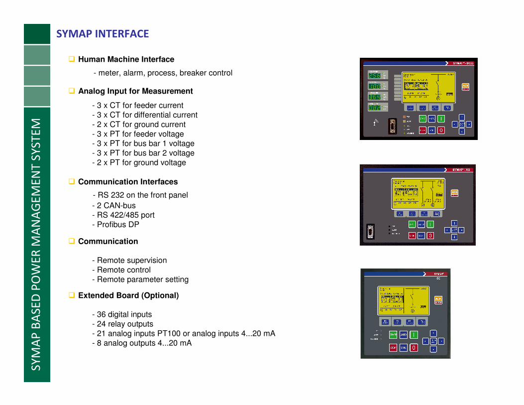
� Human Machine Interface
- meter, alarm, process, breaker control
SYMAP INTERFACE
� Analog Input for Measurement
- 3 x CT for feeder current- 3 x CT for differential current- 2 x CT for ground current- 3 x PT for feeder voltage- 3 x PT for bus bar 1 voltage- 3 x PT for bus bar 2 voltage- 2 x PT for ground voltage
� Communication
- Remote supervision- Remote control- Remote parameter setting
� Communication Interfaces
- RS 232 on the front panel
- 2 CAN-bus- RS 422/485 port- Profibus DP
� Extended Board (Optional)
- 36 digital inputs- 24 relay outputs- 21 analog inputs PT100 or analog inputs 4...20 mA- 8 analog outputs 4...20 mA

SY
MA
P B
AS
ED
PO
WE
R M
AN
AG
EM
EN
T S
YS
TE
MPOWER CONNECTION
� Medium voltage connection via transformer
� Direct low voltage connection
� Direct sync function up to 3 buses
� Differential protection available
� Easy integration to switchboard
� Direct signals for diesel control

SY
MA
P B
AS
ED
PO
WE
R M
AN
AG
EM
EN
T S
YS
TE
MDIESEL CONTROL AND SUPERVISING
SPECIALSUPERVISINGSTOP
PROCEDURESTART
PROCEDURESTOPSTART
Diesel Control
and Supervising
- Key- Remote- Load Control- Black Out
- Key- Remote- PMS- Safety
- Preglow- Start attempts- Nominal- Speed- Sync
- Safety Stop- Delay Stop- Load Deendent
Stop
- Overspeed- Lub Oil- Temperature- Other
- Commun. to Enginecontroller

SY
MA
P B
AS
ED
PO
WE
R M
AN
AG
EM
EN
T S
YS
TE
MPOWER MANAGEMENT
G1
SYMAP®
G2
SYMAP®
G3
SYMAP®
G4
SYMAP®
� Multimaster System
� 4 independent Nets
� Load dependent Start / Stop
� Load Sharing – Balanced / Unbalanced
� Frequency Control
� Voltage Regulator
� Power Factor Control
� Black Out Management
� Big consumer request
� Shaft Generator
� Up to 8 Engines

SY
MA
P B
AS
ED
PO
WE
R M
AN
AG
EM
EN
T S
YS
TE
MANSI no. Protection Function
15 Matching device (motorpoti)
24 Overexcitation protection
25 /A Automatic synchronizing
27 Undervoltage, instantaneous, definite time
27B Bus undervoltage, definite time
32 Overload relay
37 Undercurrent protection
40Q Loss of excitation
46 Reverse phase
47 Phase sequence voltage
49 Thermal overload
50BF Breaker failure
50 Overcurrent, instantaneous
50G/N Current earth fault, instantaneous
51 AC time overcurrent, definite time, IDMT (6 curves)
51V Voltage restrained overcurrent
51G/N AC ground overcurrent, definite time, IDMT (6 curves)
51LR Locked rotor
59 Overvoltage relay, instantaneous, definite time inverse
59B Bus overvoltage relay, definite time
59N Residual overvoltage
64 Ground overvoltage
66 Start inhibit
67 AC directional overcurrent, definite time, IDMT
67GS/GD AC directional earth fault, definite time
78 Vector surge supervision
78S Out-of-step tripping
79 Auto reclosing
81 Frequency supervision
81B Bus frequency supervision
86 Electrical lock out
87M Motor differential
87T Transformer differential
87G Generator differential
87LD Line differential
87N Restrict earth fault relay
94 Trip circuit supervision
95i Inrush blocking
-- FF Fuse failure (voltages)
ANSII PROTECTION
� Transformer
� Generator
� Motor
� Feeder
� Line

SY
MA
P B
AS
ED
PO
WE
R M
AN
AG
EM
EN
T S
YS
TE
M
PROFIBUS or MODBUS
DG control 1 DG control 2 DG control 3 DG control xDG control 4
HMI – touch screenALARM system
SYSTEM CONFIGURATION – ALARM SYSTEM
Optional
Traffic
Controller
Traffic
Controller
� Multiple data access, monitoring
� Redundant visualization
� Comprehensive overview of power plant
� Alarm ANSII functions
� Graphics interpretation
� Diesel START / STOP
� Load sharing settings
� Process value display
� Up to 8 SYMAP-BCG Diesel Generators
� 15” touch screen
� Diesel supervision available
� Diesel protection available

SY
MA
P B
AS
ED
PO
WE
R M
AN
AG
EM
EN
T S
YS
TE
M
PROFIBUS or MODBUS
DG control 1 DG control 2 DG control 3 DG control xDG control 4
HMI – touch screenPLC unit
SYSTEM CONFIGURATION – PLC
Optional
� Additional diesel supervision
� Digital signal monitoring
� Analog signal monitoring
� Additional PLC functions

SY
MA
P B
AS
ED
PO
WE
R M
AN
AG
EM
EN
T S
YS
TE
M
TCP/IP connection
DG control 1 DG control 2 DG control 3 DG control xDG control 4
HMI – touch screen
SYSTEM CONFIGURATION – MULTI PANEL
HMI – remote module
PROFIBUS or MODBUS
� Up to 5 remote modules / panels
� Alarm ANSII functions
� 10“ – 15“ touch screen
� Ethernet connection

SY
MA
P B
AS
ED
PO
WE
R M
AN
AG
EM
EN
T S
YS
TE
M
� Panel AGP3000 - PROFACE
� Display Size: 3.8” to 15”� Screen Type: TFT, STN color touch screens� Analog Resistive Touch Screens (no grid)� Ethernet: 10Base-T/100Base-TX
� USB: Two USB 1.1 Host Type A� COM Port 1: RS-232/422/485
� COM Port 2: RS-422/485� CompactFlash card slot Type II� Remote Data Monitoring and reporting� Expansion bus port for optional communication modules� Global Certification: RoHS, UL Listed C1 Div 2, CSA, CE
HMI CONTROL PANEL SPECIFICATION
SY
MA
P B
AS
ED
PO
WE
R M
AN
AG
EM
EN
T S
YS
TE
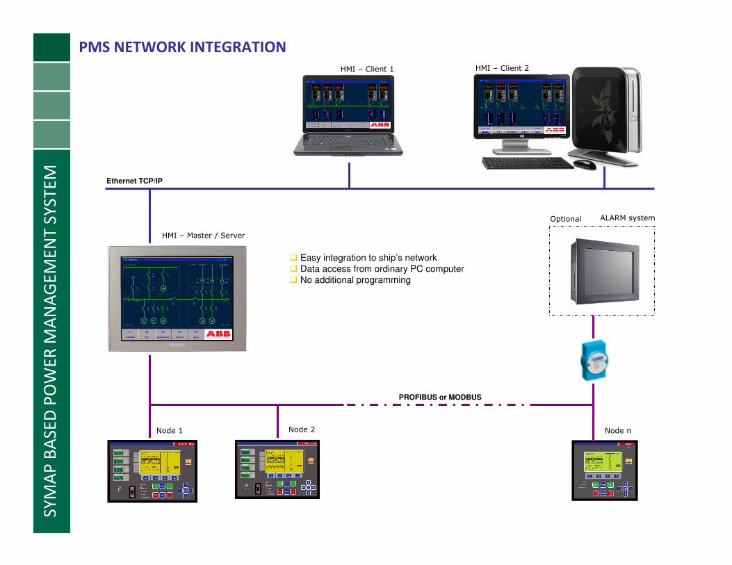
MPMS NETWORK INTEGRATION
� Easy integration to ship’s network
� Data access from ordinary PC computer
� No additional programming
Node 1 Node 2 Node n
PROFIBUS or MODBUS
Ethernet TCP/IP
HMI – Master / Server
HMI – Client 1 HMI – Client 2
ALARM systemOptional

SYMAP BASED POWER MANAGEMENT SYSTEMG
RA
PH
ICS
EX
AM
PLE
–D
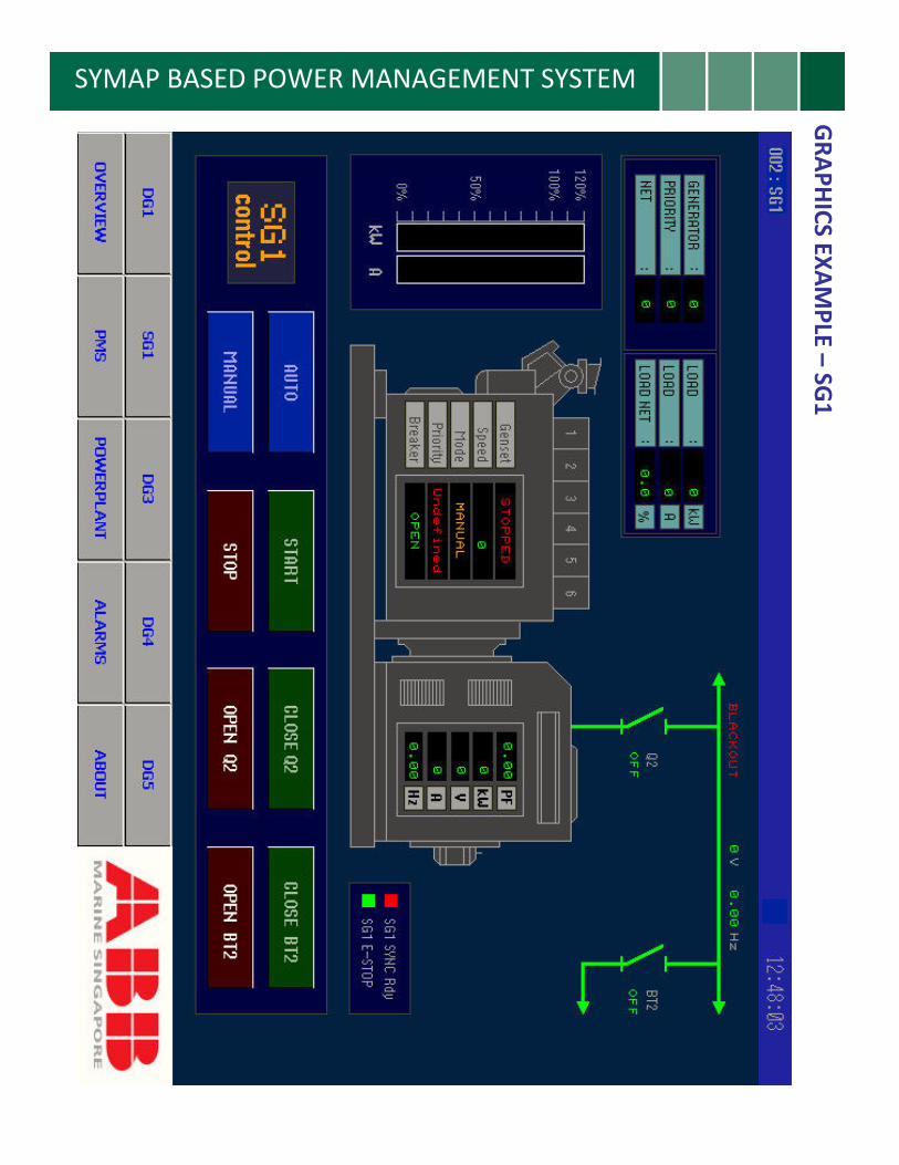
G1
SYMAP BASED POWER MANAGEMENT SYSTEMG
RA
PH
ICS
EX
AM
PLE
–S
G1

SYMAP BASED POWER MANAGEMENT SYSTEMG
RA
PH
ICS
EX
AM
PLE
–S
ING
LE
LIN
E
SYMAP BASED POWER MANAGEMENT SYSTEMG
RA
PH
ICS
EX
AM
PLE
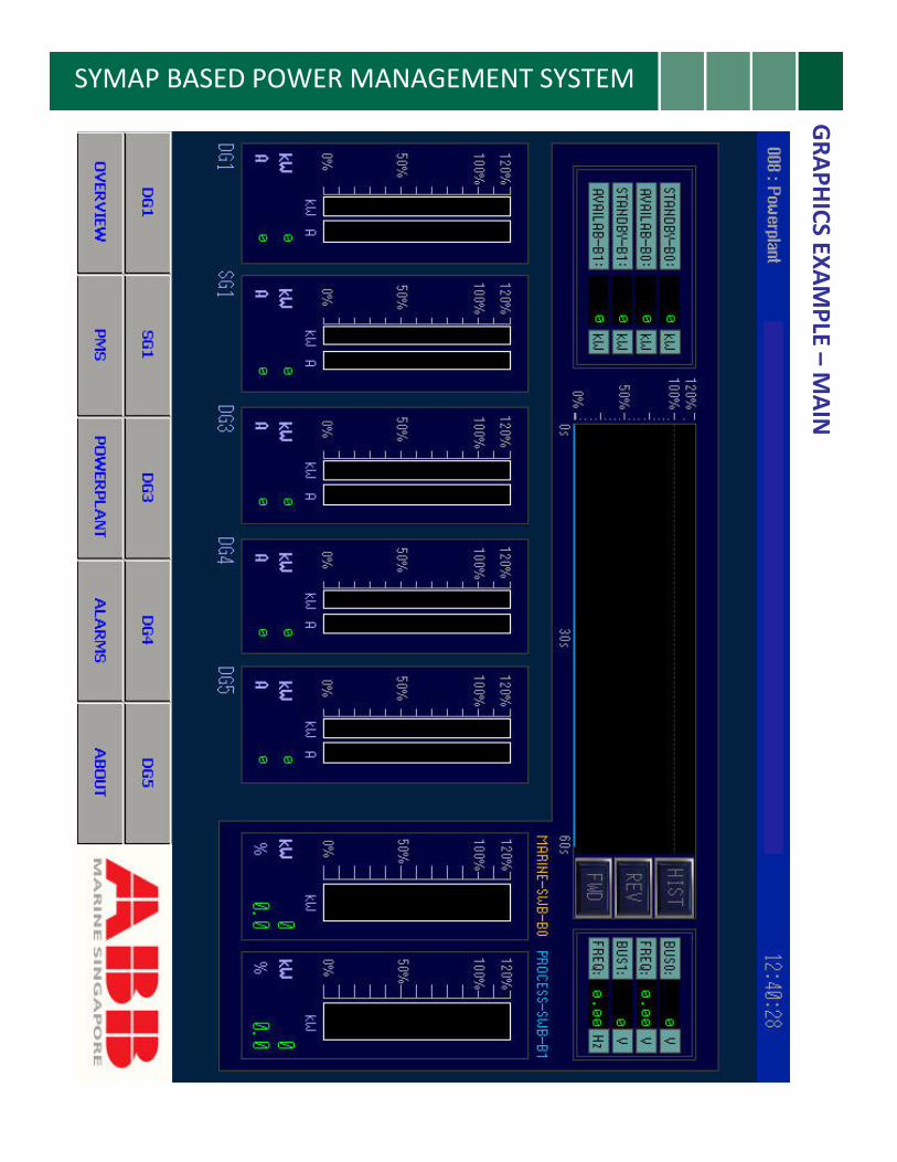
–M
AIN
SYMAP BASED POWER MANAGEMENT SYSTEMG
RA
PH
ICS
EX
AM
PLE
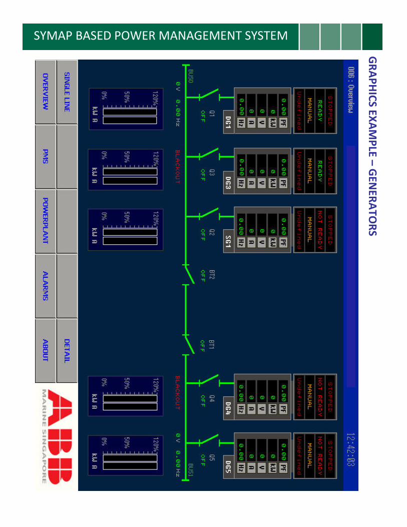
–G
EN
ER
AT
OR
S

SYMAP BASED POWER MANAGEMENT SYSTEMG
RA
PH
ICS
EX
AM
PLE
–P
MS
SE
TT
ING

SYMAP BASED POWER MANAGEMENT SYSTEMG
RA
PH
ICS
EX
AM
PLE
–LA
NG
UA
GE
OP
TIO
N
SY
MA
P B
AS
ED
PO
WE
R M
AN
AG
EM
EN
T S
YS
TE
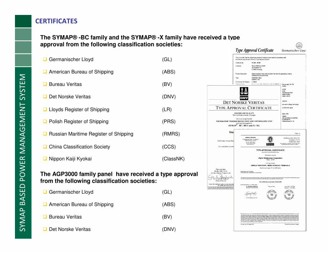
MCERTIFICATES
� Germanischer Lloyd (GL)
The SYMAP® -BC family and the SYMAP® -X family have received a type approval from the following classification societies:
� American Bureau of Shipping (ABS)
� Bureau Veritas (BV)
� Det Norske Veritas (DNV)
� Lloyds Register of Shipping (LR)
� Polish Register of Shipping (PRS)
� Russian Maritime Register of Shipping (RMRS)
� China Classification Society (CCS)
� Nippon Kaiji Kyokai (ClassNK)
The AGP3000 family panel have received a type approval from the following classification societies:
� Germanischer Lloyd (GL)
� American Bureau of Shipping (ABS)
� Bureau Veritas (BV)
� Det Norske Veritas (DNV)