SWPE08 EN PSS E Graphical Model Builder S4 - USA · FACTS models Load models Transformer models New...
2
Siemens PTI − Software Solutions At a glance PSS ® E Version 30.3 introduced the Graphical Model Builder (GMB), a powerful and easy to use dynamics model development tool based on graphic representation of control block dia- grams. Accurate power system planning re- quires that precise models be used in the simu- lation software. PSS ® E software is designed for dynamic modeling of complex systems. GMB allows specialized modeling by supporting both standard and non-standard dynamic models. Advantages of the GMB include: Based on Microsoft ® Visio ® (graphical block- diagram form) Supports a wide range of dynamic models Uses common CAD functions plus large symbol library Model flexibility using 100+ control blocks The challenge Successful operation of a power system de- pends largely on the engineer’s ability to design a system that provides safe, reliable and eco- nomical service to the customer. Advanced simulation technologies provide the means for the engineer to design and analyze power sys- tems, and assist him in making key decisions. With powerful simulation software like PSS ® E, it is possible to simulate the dynamic behavior of very large power systems and to verify the performance of these complex systems in a fast and accurate manner. However, as new technologies become avail- able for application in the power system, it is necessary to develop dynamic models to accu- rately represent their behavior. New models must be developed quickly and accurately and be fully tested prior to use in the power system simulation. Our solution GMB is a stand alone model builder and testing environment that can generate dynamic models for use in PSS ® E. GMB uses Microsoft ® Visio ® software to easily create dynamic models (Fig- ure 1). Using Visio, the GMB becomes a draw- ing tool that is simple and quick for implement- ing, editing and documenting of dynamic mod- els. PSS ® E version 30.3 incorporated GMB for: Excitation systems (AVRs) Turbine governors In rapid succession, PSS ® E will be extended to incorporate the following GMB models: Power System Stabilizers HVDC models FACTS models Load models Transformer models New source models (e.g. generic wind mod- els) New storage models Figure 1: Visio-based Graphical Model Builder Using GMB, the user can develop a wide vari- ety of dynamic models (i.e. AVR, exciter, FACTS, wind models, etc.) which can be con- structed using GMB’s built-in graphical block- diagrams coupled with Microsoft ® Visio ® . The models can be easily included in PSS ® E DYRE files without the need for compiling and linking. PSS ® E Graphical Model Builder (GMB)
Transcript of SWPE08 EN PSS E Graphical Model Builder S4 - USA · FACTS models Load models Transformer models New...

Siemens PTI − Software Solutions
At a glance PSS®E Version 30.3 introduced the Graphical Model Builder (GMB), a powerful and easy to use dynamics model development tool based on graphic representation of control block dia-grams. Accurate power system planning re-quires that precise models be used in the simu-lation software. PSS®E software is designed for dynamic modeling of complex systems. GMB allows specialized modeling by supporting both standard and non-standard dynamic models.
Advantages of the GMB include:
Based on Microsoft® Visio® (graphical block-diagram form)
Supports a wide range of dynamic models
Uses common CAD functions plus large symbol library
Model flexibility using 100+ control blocks
The challenge Successful operation of a power system de-pends largely on the engineer’s ability to design a system that provides safe, reliable and eco-nomical service to the customer. Advanced simulation technologies provide the means for the engineer to design and analyze power sys-tems, and assist him in making key decisions. With powerful simulation software like PSS®E, it is possible to simulate the dynamic behavior of very large power systems and to verify the performance of these complex systems in a fast and accurate manner.
However, as new technologies become avail-able for application in the power system, it is necessary to develop dynamic models to accu-rately represent their behavior. New models must be developed quickly and accurately and be fully tested prior to use in the power system simulation.
Our solution GMB is a stand alone model builder and testing environment that can generate dynamic models for use in PSS®E. GMB uses Microsoft® Visio® software to easily create dynamic models (Fig-ure 1). Using Visio, the GMB becomes a draw-ing tool that is simple and quick for implement-ing, editing and documenting of dynamic mod-els. PSS®E version 30.3 incorporated GMB for:
Excitation systems (AVRs)
Turbine governors
In rapid succession, PSS®E will be extended to incorporate the following GMB models:
Power System Stabilizers
HVDC models
FACTS models
Load models
Transformer models
New source models (e.g. generic wind mod-els)
New storage models
Figure 1: Visio-based Graphical Model Builder
Using GMB, the user can develop a wide vari-ety of dynamic models (i.e. AVR, exciter, FACTS, wind models, etc.) which can be con-structed using GMB’s built-in graphical block-diagrams coupled with Microsoft® Visio®. The models can be easily included in PSS®E DYRE files without the need for compiling and linking.
PSS®E Graphical Model Builder (GMB)
Published by and copyright © 2009: Siemens Energy, Inc. Power Distribution, T&D Service Solutions Siemens Power Technologies International 400 State Street PO Box 1058 Schenectady, NY 12301-1058 www.siemens.com/energy/power-technologies
Siemens AG Energy Sector E D SE PTI Freyeslebenstrasse 1 91058 Erlangen, Germany Siemens Transmission and Distribution Ltd PTI Sir William Siemens House, Princess Road Manchester, M20 2UR United Kingdom
For more information, please contact our Customer Support Center. Phone: +49 180 524 70 00 Fax: +49 180 524 24 71 (Charges depending on provider) E-mail: [email protected] Power Distribution Division Printed in Germany Printed on elementary chlorine-free bleached paper.
All rights reserved. Trademarks mentioned in this document are the property of Siemens AG, its affiliates, or their respective owners. Subject to change without prior notice. The information in this document contains general descriptions of the technical options available, which may not apply in all cases. The required technical options should therefore be specified in the contract. SWPE08-EN-200905
During model development, GMB pre-sents a stand-alone model simulation package that allows testing of the inde-pendent model. The simulation can be driven using built in signal generators and test points that allow simulating the response of the model over a full range of inputs.
Besides familiar CAD functions, such as copying, shifting, rotating, zooming, etc., the GMB system has a large symbol library which contains more than 100 basic control blocks in the form of sym-bols. The user develops the model by graphically interconnecting the basic library symbols and editing the proper-ties of each controller element via intui-tive dialog boxes. Further, the user may then use this model as a “subsystem” in the symbol library which can then be used in constructing additional models. Library components can be activated and deactivated and connected to any desired part of the system.
The symbol library “BOSL” (Block-Oriented Simulation Language) contains more than 100 different function blocks. These blocks can be combined to gen-erate any open or closed-loop control structures or logic devices by means of the graphic interface. Besides very sim-ple blocks, such as PID elements, sub-sequent PSS®E releases will provide the ability to incorporate complex “blocks”, such as FFT (Fast Fourier Transforma-tion). Parameter values can be entered and edited individually, or the default values can be used (Figure 2).
Complex open and closed-loop control and protective functions can be imple-mented with GMB. Besides the open and closed-loop control structure, signal processing structures can be defined by the user. External, user-defined subrou-tines can also be coupled (open-loop) and there is an interface to real- time applications (closed-loop).
Figure 2: Data input in masks after double click-ing
Figure 3: Special user blocks with FORTRAN statements
The block-oriented structures can be combined with FORTRAN-like terms (Figure 3), such as mathematical func-tions, logical terms or instructions, (e.g., IF / THEN / ELSE and GOTO / CON-TINUE). Input variables are available to the controllers in all units. In addition, the variables from other closed and open-loop controllers or the evaluation struc-tures can be used as input variables. All inputs and outputs of blocks can be printed or plotted.
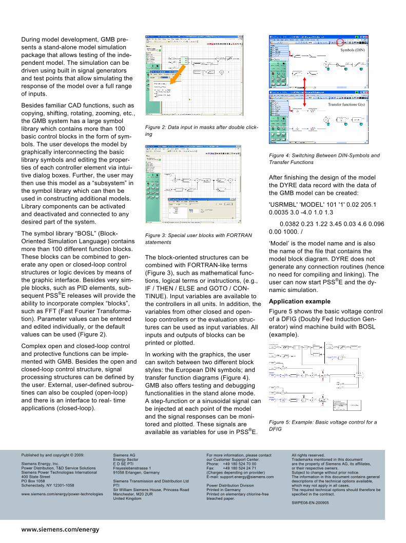
In working with the graphics, the user can switch between two different block styles: the European DIN symbols; and transfer function diagrams (Figure 4). GMB also offers testing and debugging functionalities in the stand alone mode. A step-function or a sinusoidal signal can be injected at each point of the model and the signal responses can be moni-tored and plotted. These signals are available as variables for use in PSS®E.
Symbols (DIN)
Transfer functions G(s)
Figure 4: Switching Between DIN-Symbols and Transfer Functions
After finishing the design of the model the DYRE data record with the data of the GMB model can be created:
'USRMBL' 'MODEL' 101 '1' 0.02 205.1 0.0035 3.0 -4.0 1.0 1.3
0.0382 0.23 1.22 3.45 0.03 4.6 0.096 0.00 1000. /
‘Model’ is the model name and is also the name of the file that contains the model block diagram. DYRE does not generate any connection routines (hence no need for compiling and linking). The user can now start PSS®E and the dy-namic simulation.
Application example Figure 5 shows the basic voltage control of a DFIG (Doubly Fed Induction Gen-erator) wind machine build with BOSL (example).
Figure 5: Example: Basic voltage control for a DFIG