Swivel clamp - pascaleng.co.jp
12
www.pascaleng.co.jp Swivel clamp model CTS Double acting 7MPa
Transcript of Swivel clamp - pascaleng.co.jp
www.pascaleng.co.jp
Swivel clamp
model CTSDouble acting 7MPa
1
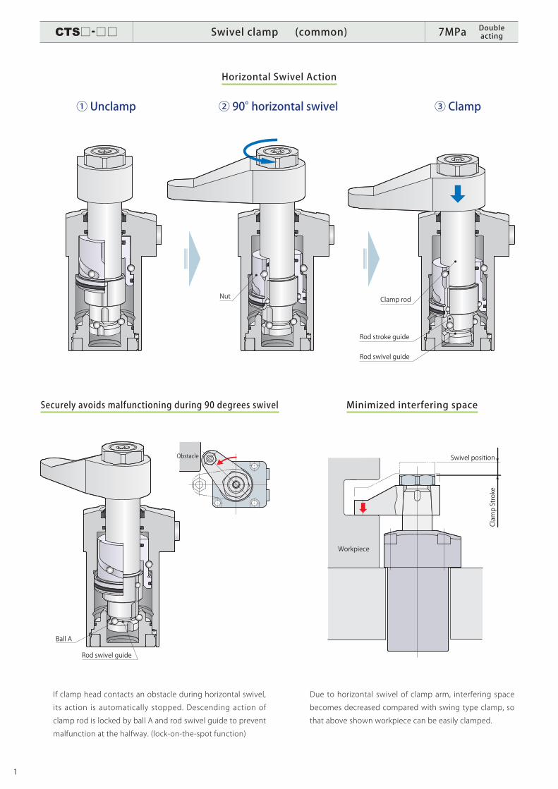
Horizontal Swivel Action
Minimized interfering space
Due to horizontal swivel of clamp arm, interfering space
becomes decreased compared with swing type clamp, so
that above shown workpiece can be easily clamped.
If clamp head contacts an obstacle during horizontal swivel,
its action is automatically stopped. Descending action of
clamp rod is locked by ball A and rod swivel guide to prevent
malfunction at the halfway. (lock-on-the-spot function)
Securely avoids malfunctioning during 90 degrees swivel
Ball A
Rod swivel guide
Obstacle
Clamp rod
① Unclamp ② 90° horizontal swivel ③ Clamp
Rod swivel guide
Rod stroke guide
Nut
Clamp Stroke
Workpiece
Swivel position
CTS□-□□ Swivel clamp (common) 7MPa Double acting
2
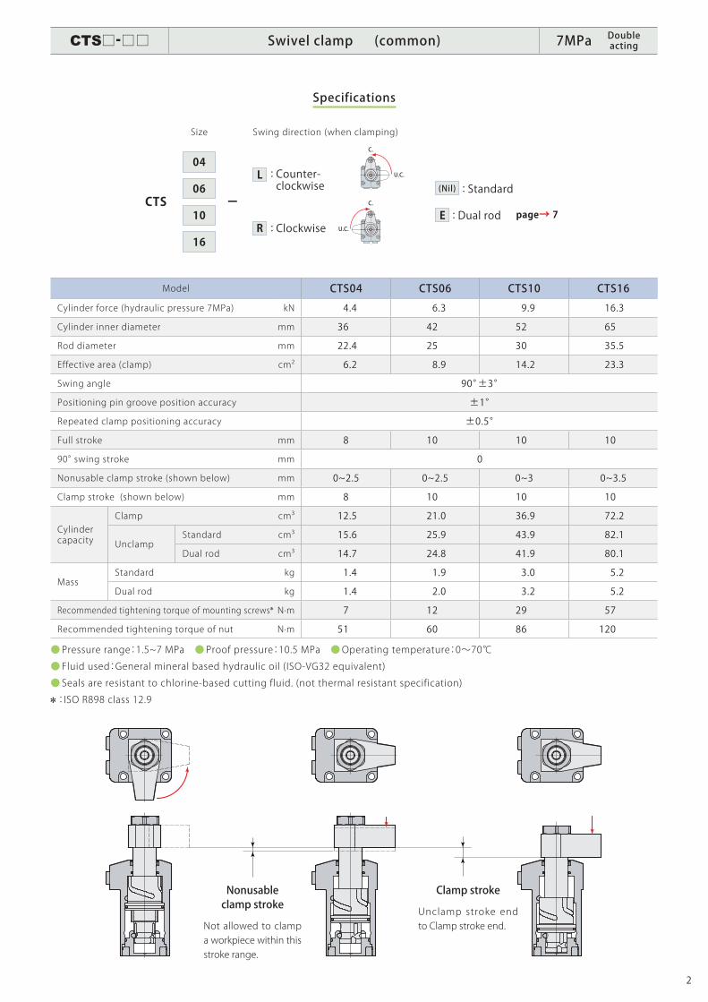
Specifications
Size Swing direction (when clamping)
Nonusable clamp stroke
Not allowed to clamp a workpiece within this stroke range.
Clamp stroke
Unclamp stroke end to Clamp stroke end.
ーCTS
04
06
10
16
L
R
: Counter- clockwise
: Clockwise: Dual rodE page→ 7
: Standard(Nil)
Model CTS04 CTS06 CTS10 CTS16
Cylinder force (hydraulic pressure 7MPa) kN 4.4 6.3 9.9 16.3
Cylinder inner diameter mm 36 42 52 65
Rod diameter mm 22.4 25 30 35.5
Effective area (clamp) cm2 6.2 8.9 14.2 23.3
Swing angle 90°±3°
Positioning pin groove position accuracy ±1°
Repeated clamp positioning accuracy ±0.5°
Full stroke mm 8 10 10 10
90° swing stroke mm 0
Nonusable clamp stroke (shown below) mm 0~2.5 0~2.5 0~3 0~3.5
Clamp stroke (shown below) mm 8 10 10 10
Cylinder capacity
Clamp cm3 12.5 21.0 36.9 72.2
UnclampStandard cm3 15.6 25.9 43.9 82.1
Dual rod cm3 14.7 24.8 41.9 80.1
MassStandard kg 1.4 1.9 3.0 5.2
Dual rod kg 1.4 2.0 3.2 5.2
Recommended tightening torque of mounting screws N·m 7 12 29 57
Recommended tightening torque of nut N·m 51 60 86 120
● Pressure range:1.5~7 MPa ● Proof pressure:10.5 MPa ●Operating temperature:0~70℃
● Fluid used:General mineral based hydraulic oil (ISO-VG32 equivalent)
● Seals are resistant to chlorine-based cutting fluid. (not thermal resistant specification)
:ISO R898 class 12.9
C.
C.
U.C.
U.C.
CTS□-□□ Swivel clamp (common) 7MPa Double acting
3
Performance table
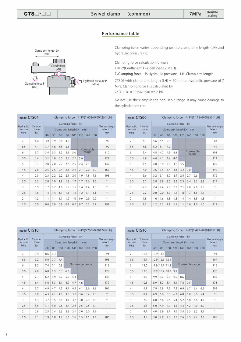
Clamping force varies depending on the clamp arm length (LH) and
hydraulic pressure (P).
Clamping force calculation formula
F=P/(Coefficient 1+Coefficient 2×LH)
F:Clamping force P:Hydraulic pressure LH:Clamp arm length
CTS06 with clamp arm length (LH) = 50 mm at hydraulic pressure of 7
MPa, Clamping force F is calculated by
7/(1.118+0.00256×50)=5.6 kN
Do not use the clamp in the nonusable range. It may cause damage to
the cylinder and rod.
model CTS04 Clamping force F=P/(1.603+0.00426×LH)
Hydraulic pressure MPa
Cylinder forcekN
Clamping force kNMax. arm length Max. LHmm
Clamp arm length LH mm
40 50 60 80 100 120 140 160
7 4.4 3.9 3.9 3.8 3.6 90
6.5 4.1 3.7 3.6 3.5 3.3 99
6 3.7 3.4 3.3 3.2 3.1 3.0 110
5.5 3.4 3.1 3.0 3.0 2.8 2.7 2.6 121
5 3.1 2.8 2.8 2.7 2.6 2.5 2.4 2.3 142
4.5 2.8 2.5 2.5 2.4 2.3 2.2 2.1 2.0 2.0 165
4 2.5 2.3 2.2 2.2 2.1 2.0 1.9 1.8 1.8 198
3.5 2.2 2.0 1.9 1.9 1.8 1.7 1.7 1.6 1.5 ↑
3 1.9 1.7 1.7 1.6 1.5 1.5 1.4 1.4 1.3 ↑
2.5 1.6 1.4 1.4 1.3 1.3 1.2 1.2 1.1 1.1 ↑
2 1.2 1.1 1.1 1.1 1.0 1.0 0.9 0.9 0.9 ↑
1.5 0.9 0.8 0.8 0.8 0.8 0.7 0.7 0.7 0.7 198
model CTS10 Clamping force F=P/(0.706+0.00174×LH)
Hydraulic pressure MPa
Cylinder forcekN
Clamping force kNMax. arm length Max. LHmm
Clamp arm length LH mm
60 80 100 120 140 160 180 200
7 9.9 8.6 8.3 94
6.5 9.2 8.0 7.7 7.4 103
6 8.5 7.4 7.1 6.8 115
5.5 7.8 6.8 6.5 6.3 6.0 129
5 7.1 6.2 5.9 5.7 5.5 5.3 148
4.5 6.4 5.6 5.3 5.1 4.9 4.7 4.6 172
4 5.7 4.9 4.7 4.5 4.4 4.2 4.1 3.9 3.8 206
3.5 5.0 4.3 4.1 4.0 3.8 3.7 3.6 3.4 3.3 ↑
3 4.3 3.7 3.5 3.4 3.3 3.2 3.0 2.9 2.8 ↑
2.5 3.5 3.1 3.0 2.8 2.7 2.6 2.5 2.5 2.4 ↑
2 2.8 2.5 2.4 2.3 2.2 2.1 2.0 2.0 1.9 ↑
1.5 2.1 1.9 1.8 1.7 1.6 1.6 1.5 1.5 1.4 206
model CTS06 Clamping force F=P/(1.118+0.00256×LH)
Hydraulic pressure MPa
Cylinder forcekN
Clamping force kNMax. arm length Max. LHmm
Clamp arm length LH mm
50 60 80 100 120 140 160 180
7 6.3 5.6 5.5 5.3 83
6.5 5.8 5.2 5.1 4.9 92
6 5.4 4.8 4.7 4.5 4.4 101
5.5 4.9 4.4 4.3 4.2 4.0 114
5 4.5 4.0 3.9 3.8 3.6 3.5 129
4.5 4.0 3.6 3.5 3.4 3.3 3.2 3.0 149
4 3.6 3.2 3.1 3.0 2.9 2.8 2.7 2.6 176
3.5 3.1 2.8 2.8 2.6 2.5 2.5 2.4 2.3 2.2 214
3 2.7 2.4 2.4 2.3 2.2 2.1 2.0 2.0 1.9 ↑
2.5 2.2 2.0 2.0 1.9 1.8 1.8 1.7 1.6 1.6 ↑
2 1.8 1.6 1.6 1.5 1.5 1.4 1.4 1.3 1.3 ↑
1.5 1.3 1.2 1.2 1.1 1.1 1.1 1.0 1.0 1.0 214
model CTS16 Clamping force F=P/(0.429+0.00107×LH)
Hydraulic pressure MPa
Cylinder forcekN
Clamping force kNMax. arm length Max. LHmm
Clamp arm length LH mm
60 80 100 120 140 160 180 200
7 16.3 13.9 13.6 94
6.5 15.1 12.9 12.6 12.1 104
6 14.0 11.9 11.7 11.2 115
5.5 12.8 10.9 10.7 10.3 9.9 130
5 11.6 9.9 9.7 9.3 9.0 8.6 149
4.5 10.5 8.9 8.7 8.4 8.1 7.8 7.5 173
4 9.3 7.9 7.8 7.5 7.2 6.9 6.7 6.4 6.2 208
3.5 8.1 6.9 6.8 6.5 6.3 6.0 5.8 5.6 5.4 ↑
3 7.0 6.0 5.8 5.6 5.4 5.2 5.0 4.8 4.7 ↑
2.5 5.8 5.0 4.9 4.7 4.5 4.3 4.2 4.0 3.9 ↑
2 4.7 4.0 3.9 3.7 3.6 3.5 3.3 3.2 3.1 ↑
1.5 3.5 3.0 2.9 2.8 2.7 2.6 2.5 2.4 2.3 208
Nonusable range Nonusable
range
Nonusable range Nonusable range
Clamping force F(kN)
Hydraulic pressure P(MPa)
Cylinder force(kN)
Clamp arm length LH(mm)
CTS□-□□ Swivel clamp (common) 7MPa Double acting
4
A2
A1
m2
m1
B
0.000.0027
0.4
0.01 0.02 0.03 0.04 0.05
1.5
1.0
0.5
0
t =0.0167
I
0.000.0029
0.4
0.01 0.02 0.03 0.04 0.05
1.5
1.0
0.5
0
t =0.0183
I
0.000.009
0.4
0.02 0.04 0.06 0.10 0.12 0.140.08
1.5
1.0
0.5
0
t =0.0581
I
0.010.000.0056
0.4
0.02 0.03 0.04 0.05 0.06 0.07 0.08
1.5
1.0
0.5
0
t =0.0350
I
Swing time(sec)
Moment of inertia (kg・m2)
Nonusable range
Shortest swing time
Shortest swing time calculation formula
Swing time(sec)
Moment of inertia (kg・m2)
Nonusable range
Shortest swing time
Shortest swing time calculation formula
Swing time(sec)
Moment of inertia (kg・m2)
Nonusable range
Shortest swing time
Shortest swing time calculation formula
Swing time(sec)
Moment of inertia (kg・m2)
Nonusable range
Shortest swing time
Shortest swing time calculation formula
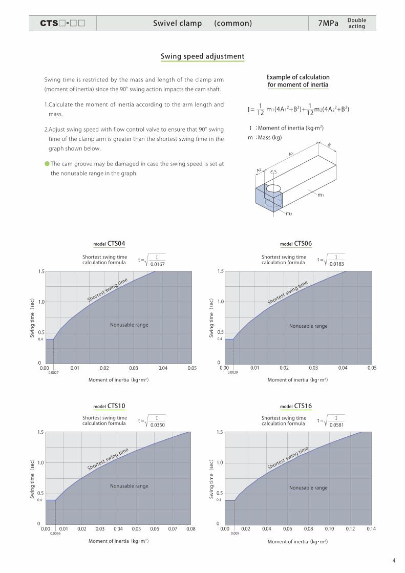
Swing speed adjustment
model CTS06
model CTS16
model CTS04
model CTS10
Example of calculation for moment of inertia
Swing time is restricted by the mass and length of the clamp arm
(moment of inertia) since the 90° swing action impacts the cam shaft.
1. Calculate the moment of inertia according to the arm length and
mass.
2. Adjust swing speed with flow control valve to ensure that 90° swing
time of the clamp arm is greater than the shortest swing time in the
graph shown below.
● The cam groove may be damaged in case the swing speed is set at
the nonusable range in the graph.
I :Moment of inertia (kg·m2)
m :Mass (kg)
I = 112 m1(4A12+B2)+ 112m2(4A2
2+B2)
CTS□-□□ Swivel clamp (common) 7MPa Double acting
5
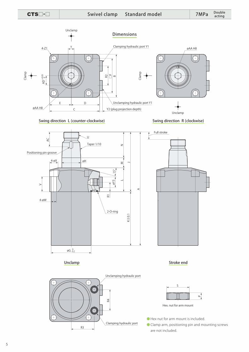
Dimensions
● Hex nut for arm mount is included.
● Clamp arm, positioning pin and mounting screws
are not included.
Swing direction L (counter-clockwise) Swing direction R (clockwise)
Unclamp Stroke end
AC
NM
L
JK±0.1
A
V
4-øW
øG 0 -0.2
15°
R1
øY3
øH4-øX
U
R4
R3
B□FR2
T
E D
C
4-Z1
AD+0.050
øAA H8
øAA H8
S
P
Y2 (plug projection depth)
Clamping hydraulic port Y1
Unclamping hydraulic port Y1
Unclamp
Unclamp
Clamp
Clamp
Unclamping hydraulic port
Clamping hydraulic port
2-O-ring
Taper 1/10
Positioning pin groove
Full stroke
Hex. nut for arm mount
CTS□-□ Swivel clamp Standard model 7MPa Double acting
6
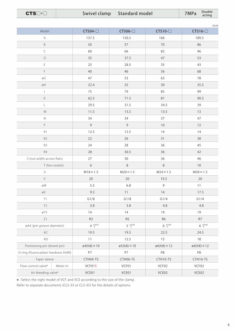
mm
Model CTS04-□ CTS06-□ CTS10-□ CTS16-□
A 137.5 150.5 166 189.5
B 50 57 70 86
C 60 66 82 96
D 35 37.5 47 53
E 25 28.5 35 43
F 40 46 56 68
ø G 47 53 63 78
ø H 22.4 25 30 35.5
J 75 79 85 99
K 62.5 71.5 81 90.5
L 29.5 31.5 34.5 39
M 11.5 13.5 13.5 13
N 34 34 37 47
P 9 9 10 12
R1 12.5 12.5 14 14
R2 22 26 31 38
R3 24 28 36 45
R4 28 30.5 36 42
S (nut width across flats) 27 30 36 46
T (hex socket) 6 8 8 10
U M18×1.5 M20×1.5 M24×1.5 M30×1.5
V 20 20 19.5 20
ø W 5.5 6.8 9 11
ø X 9.5 11 14 17.5
Y1 G1/8 G1/8 G1/4 G1/4
Y2 3.8 3.8 4.8 4.8
ø Y3 14 14 19 19
Z1 R3 R5 R6 R7
ø AA (pin groove diameter) 4 + 0.018 0 5 + 0.018 0 6 + 0.018 0 6 + 0.018 0
AC 19.5 19.5 22.5 24.5
AD 11 12.5 15 18
Positioning pin (dowel pin) ø4(h8)×10 ø5(h8)×10 ø6(h8)×12 ø6(h8)×12
O-ring (fluorocarbon hardness Hs90) P7 P7 P8 P8
Taper sleeve CTH04-TS CTH06-TS CTH10-TS CTH16-TS
Flow control valve Meter-in VCF01S VCF01 VCF02 VCF02
Air bleeding valve VCE01 VCE01 VCE02 VCE02
:Select the right model of VCF and VCE according to the size of the clamp.
Refer to separate documents (CLS-33 or CLS-35) for the details of options.
CTS□-□ Swivel clamp Standard model 7MPa Double acting

7
Example
Size Swing direction (when clamping)
ーCTS
04
06
10
16
L
R
: Counter- clockwise
: Clockwise
: Dual rodE
Dual rod
: Model CTS unclamp detection shall be made
by the rod swing angle because of a horizontal
swiveling arm mechanism.
Hydlauricpressure(two circuits)
Workpiece
Unclamping detectionProximity Switch
Clamping detectionProximity Switch
Rod
Scraper
Rod
C.
C.
U.C.
U.C.
CTS□-□E Swivel clamp Dual rod 7MPa Double acting
8
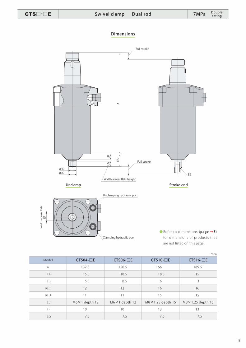
Dimensions
Unclamp Stroke end
mm
Model CTS04-□E CTS06-□E CTS10-□E CTS16-□E
A 137.5 150.5 166 189.5
EA 15.5 18.5 18.5 15
EB 5.5 8.5 6 3
ø EC 12 12 16 16
ø ED 11 11 15 15
EE M6×1 depth 12 M6×1 depth 12 M8×1.25 depth 15 M8×1.25 depth 15
EF 10 10 13 13
EG 7.5 7.5 7.5 7.5
● Refer to dimensions (page →5) for dimensions of products that
are not listed on this page.
A
øEC
EBEG
EA
øED
EF
EE
Unclamping hydraulic port
Clamping hydraulic port
Full stroke
Full stroke
Width across flats height
width across flats
CTS□-□E Swivel clamp Dual rod 7MPa Double acting
9
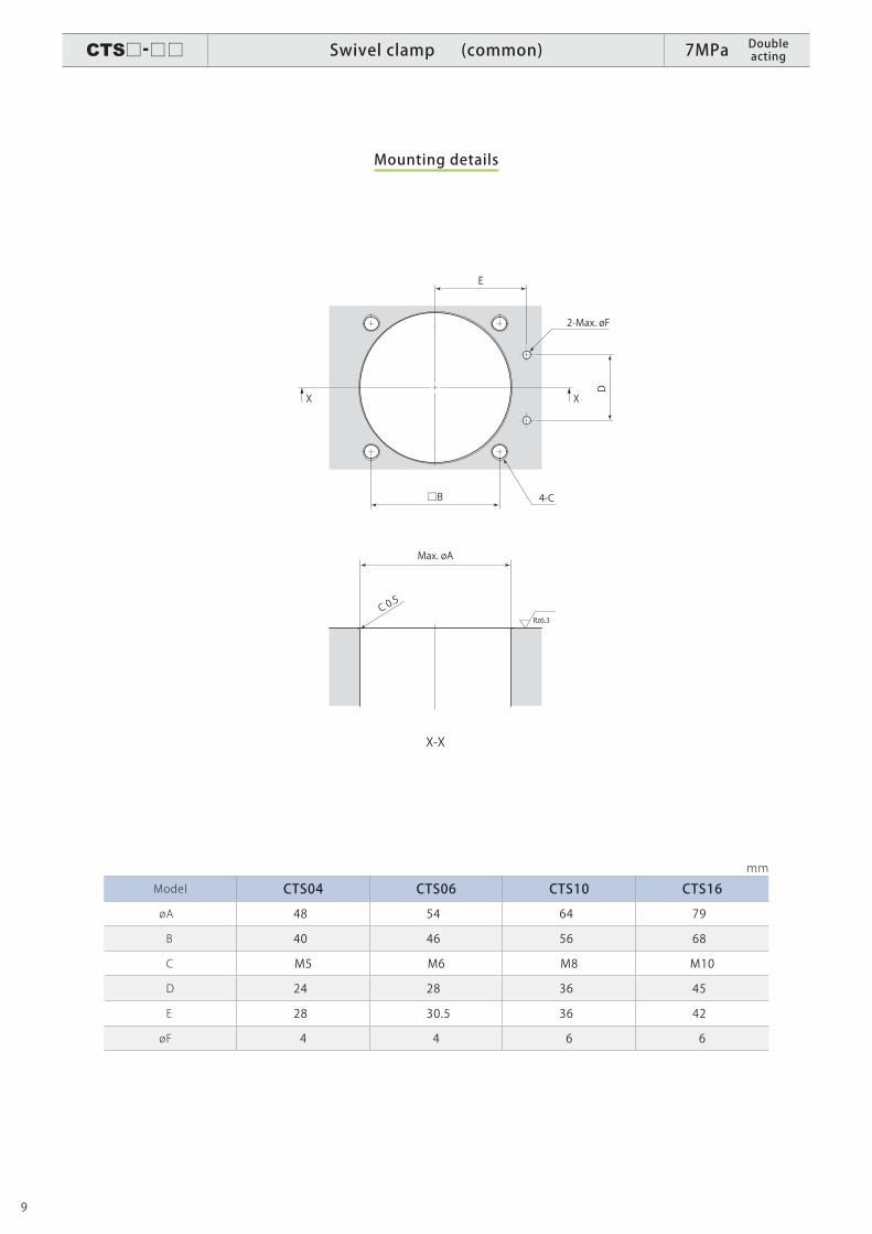
Mounting details
mm
Model CTS04 CTS06 CTS10 CTS16
ø A 48 54 64 79
B 40 46 56 68
C M5 M6 M8 M10
D 24 28 36 45
E 28 30.5 36 42
ø F 4 4 6 6
Max. øA
C 0.5
2-Max. øF
□B 4-C
D
E
X-X
X X
Rz6.3
CTS□-□□ Swivel clamp (common) 7MPa Double acting
10
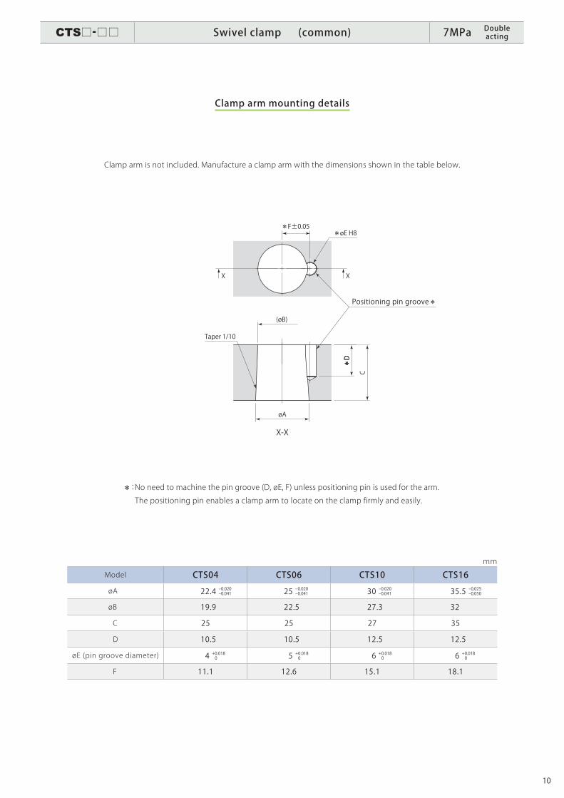
Clamp arm mounting details
mm
Model CTS04 CTS06 CTS10 CTS16
ø A 22.4 -0.020-0.041 25 -0.020-0.041 30 -0.020-0.041 35.5 -0.025-0.050
ø B 19.9 22.5 27.3 32
C 25 25 27 35
D 10.5 10.5 12.5 12.5
ø E (pin groove diameter) 4 + 0.018 0 5 + 0.018 0 6 + 0.018 0 6 + 0.018 0
F 11.1 12.6 15.1 18.1
Clamp arm is not included. Manufacture a clamp arm with the dimensions shown in the table below.
: No need to machine the pin groove (D, øE, F) unless positioning pin is used for the arm.
The positioning pin enables a clamp arm to locate on the clamp firmly and easily.
(øB)
C
X-X
X X
øA
Taper 1/10
Positioning pin groove
D
øE H8F±0.05
D
CTS□-□□ Swivel clamp (common) 7MPa Double acting

PA-576E-32018. 09 Specifications are subject to change without prior notice.
Itami, Hyogo, Japan 664-8502TEL. 072-777-3333 FAX. 072-777-3520
CERTIFICATE OF APPROVAL ISO9001
PA-419E-32018. 08