
Switch Ratings, What's it all Mean? - AeroElectric Connection
13
Copyright 1998 Robert L. Nuckolls, III, Wichita, Kansas. All rights reserved. This document may be reproduced electronically or mechanically for distribution in a not-for profit, educational endeavor if it is published in its entirety and without modification. Page 1 Bob Nuckolls 6936 Bainbridge Road Wichita, Kansas 67226-1008 Voice/Fax: 316-685-8617 E-mail: [email protected] Switch Ratings, What's it all Mean? Just catching up on piles of snail-mail and e-mail that tends to build up while we are flitting from fly-in to seminar. Picked up a copy of the Oct 97 issue of Van's Air Force and read an article on switch selection that makes some good points but arrives at the wrong conclusion. The author was privileged to observe some work done at UL Laboratories on switches and expressed some concern for builder naivety with respect to AC versus DC ratings. He correctly cites an increased difficulty for breaking a DC circuit versus an AC circuit . . . particularly when inductive loads are involved. Quoting from the article: "Typical of this is the roller and bar micro switches made by MICRO(switch) Corporation. Rated at 10 amps for 125/250 volt AC, the same switch can only carry 0.15 amps at 250 volts DC! The voltage stayed the same!" The statement is true but not relevant to our task. We're not building 250-volt airplanes, we build 14 and a few 28-volt airplanes. Check out this data table plagiarized from the same Microswitch catalog . As one picks from the various switch products in the catalog, an "electrical code rating" is quoted for each device . . . the chart above states the ratings for each code. When one buys a toggle switch from Microswitch . . . the choices above are all inclusive. The chart cites a variety of conditions for applying switches. Various combinations of AC or DC voltage along with loads can have a profound effect on switch life. Induc- tive loads do call for some derating . . about 25%. However, look at the column for lamp loads . . . it calls for the greatest derating . . . on the order of 75%! I'll call your attention to the 250 VDC column for ALL switches. Note that none are rated at more than 0.5 amps in spite of the fact that the same switches are good for 6 amps at 250 VAC and MANY more amps at lower voltages. Quoting again from the article: "Those of you who can still remember the old Kettering coil ignition systems will recall that when the condenser in the distributor went bad, the points generally turned blue and melted down in a few minutes. . . . " The cited capacitor was to slow down a the rate-of-rise for voltage across relatively slow moving, cam driven switch contacts. If an arc were allowed to form between the opening points, energy intended to spark combustible mixtures in a cylinder would be used up at the points instead . . . the most notable result of bad "condenser" was the car ran very badly if at all . . . the points were indeed subject to more electrical stress but seldom for very long . . . this situation demanded timely repairs. Switches of choice for airplane panels are not cam driven. Toggles use spring loaded, over-center mechanisms that provide higher contact spreading velocities. Going on with the article . . . "Cockpit switches don't have benefit of the condensers to absorb the electrical inertia present in a DC circuit and as a result, the gap temperatures get hot enough to weld contacts. That includes AC rated switches, even those made with exotic high temperature alloys." The Kettering ignition example is an excellent way to illustrate"inductive" circuits. However, there are few such circuits in an airplane. Most notable of these are battery and starter contactor coils. We don't put "condensers" on these systems but we do install "catch diodes" or MOVs (metal oxide varistor) to protect switch contacts. This has been standard practice in airplanes for 30+ years (just worked on my kid's '72 Chevy truck today and saw a 1N4001 diode crimped into the connector for the air-conditioning compres- sor clutch). The article also overlooks the differences in physics between burning contacts and welding them.
Transcript of Switch Ratings, What's it all Mean? - AeroElectric Connection

Copyright 1998 Robert L. Nuckolls, III, Wichita, Kansas. All rights reserved. This document may be reproduced electronically or mechanicallyfor distribution in a not-for profit, educational endeavor if it is published in its entirety and without modification.
Page 1
Bob Nuckolls6936 Bainbridge RoadWichita, Kansas 67226-1008Voice/Fax: 316-685-8617E-mail: [email protected]
Switch Ratings, What's it all Mean?
Just catching up on piles of snail-mail and e-mail that tendsto build up while we are flitting from fly-in to seminar.Picked up a copy of the Oct 97 issue of Van's Air Force andread an article on switch selection that makes some goodpoints but arrives at the wrong conclusion. The author wasprivileged to observe some work done at UL Laboratorieson switches and expressed some concern for builder naivetywith respect to AC versus DC ratings.
He correctly cites an increased difficulty for breaking a DCcircuit versus an AC circuit . . . particularly when inductiveloads are involved. Quoting from the article:
"Typical of this is the roller and bar micro switches madeby MICRO(switch) Corporation. Rated at 10 amps for125/250 volt AC, the same switch can only carry 0.15 ampsat 250 volts DC! The voltage stayed the same!"
The statement is true but not relevant to our task. We're notbuilding 250-volt airplanes, we build 14 and a few 28-voltairplanes. Check out this data table plagiarized from thesame Microswitch catalog . As one picks from the variousswitch products in the catalog, an "electrical code rating" isquoted for each device . . . the chart above states the ratingsfor each code. When one buys a toggle switch fromMicroswitch . . . the choices above are all inclusive.
The chart cites a variety of conditions for applyingswitches. Various combinations of AC or DC voltage alongwith loads can have a profound effect on switch life. Induc-tive loads do call for some derating . . about 25%. However,look at the column for lamp loads . . . it calls for the greatestderating . . . on the order of 75%!
I'll call your attention to the 250 VDC column for ALLswitches. Note that none are rated at more than 0.5 amps inspite of the fact that the same switches are good for 6 ampsat 250 VAC and MANY more amps at lower voltages.
Quoting again from the article:
"Those of you who can still remember the old Ketteringcoil ignition systems will recall that when the condenser inthe distributor went bad, the points generally turned blueand melted down in a few minutes. . . . "
The cited capacitor was to slow down a the rate-of-rise forvoltage across relatively slow moving, cam driven switchcontacts. If an arc were allowed to form between theopening points, energy intended to spark combustiblemixtures in a cylinder would be used up at the points instead. . . the most notable result of bad "condenser" was the carran very badly if at all . . . the points were indeed subject tomore electrical stress but seldom for very long . . . thissituation demanded timely repairs. Switches of choice forairplane panels are not cam driven. Toggles use springloaded, over-center mechanisms that provide higher contactspreading velocities. Going on with the article . . .
"Cockpit switches don't have benefit of the condensers toabsorb the electrical inertia present in a DC circuit and asa result, the gap temperatures get hot enough to weldcontacts. That includes AC rated switches, even those madewith exotic high temperature alloys."
The Kettering ignition example is an excellent way toillustrate"inductive" circuits. However, there are few suchcircuits in an airplane. Most notable of these are battery andstarter contactor coils. We don't put "condensers" on thesesystems but we do install "catch diodes" or MOVs (metaloxide varistor) to protect switch contacts. This has beenstandard practice in airplanes for 30+ years (just worked onmy kid's '72 Chevy truck today and saw a 1N4001 diodecrimped into the connector for the air-conditioning compres-sor clutch). The article also overlooks the differences inphysics between burning contacts and welding them.

Copyright 1998 Robert L. Nuckolls, III, Wichita, Kansas. All rights reserved. This document may be reproduced electronically or mechanicallyfor distribution in a not-for profit, educational endeavor if it is published in its entirety and without modification.
Page 2
Toggle Switch Ratings Table from Microswitch Catalog
ElectCode
Rating
28 VDC 115VDC
250VDC
115 VAC 230VAC
IND RES LAMP RES RES IND RES LAMP RES
1 15 20 5 .75 .5 10 15 3 6
2 10 15 4 .75 .5 7 15 2 6
3 15 20 7 .75 .5 15 15 4 6
4 10 18 5 .75 .5 8 11 2 6
5 12 20 5 .75 .5 15 15 4 6
6 10 18 4 .75 .5 8 11 2 6
Most damage to switches is done during the breaking of acircuit where an arc forms in the widening gap. Dependingon contact spreading velocity -AND- thermal mass of thecontacts, this can be the most stressful task for switching.However, this is when the contacts are getting farther apart. . an improbable scenario for welding.
The physics for closing a circuit are different. Here, poten-tially high inrush currents are impressed across contacts thatmay have small hills and valleys eroded in them fromprevious switch openings. These little hills become potentialwelding material when the large inrush current is forced toflow through a small cross section of material. This canhappen to any switch with either DC or AC.
By-in-large, switched circuits in airplanes are resistive butlet's look again at the purloined data from Microswitch. Innearly all cases (except Code 5) DC ratings at 28 VDC forthe switches cited are better than the ratings for 115 VAC!(????) As a general rule of thumb, I've told builders that the115 VAC rating is directly translatable to 14 VDC applica-tions. I'll offer the chart above in support of this advice. Thearticle continues . . .
"What often happened during UL testing was that thepoints welded shut, making it impossible to open thecircuit."
Sure, let me pick the test parameters and I can probablyweld about any switch shut. Keep in mind that UL has to testfor EVERY possible safety contingency in product designand utilization. We design and build failure tolerant designs
and select electrical devices that perform in narrowlydefined settings. In years of fiddling with airplanes, I'venever seen a manual switch weld shut. I've seen themcorrode open, I've seen over-center springs rust out, I've seewires break off the back, etc. But never a welding. Now,contactors weld . . . with some frequency . . . but that'sanother topic. Electrical stresses that weld switch contactsin the lab simply don't exist in airplanes. Most switchfailures I've observed show up when the switch fails to makegood contact . . . mostly from dis-use and corrosion asopposed to electrical abuse.
The heaviest currents handled by panel switches are land-ing/taxi lights (which have their own special inrush values-see "lamp" ratings in table above), and pitot heat. For most14-volt airplanes this is about 8 amps. Everything else dropsrapidly from there. I can also tell you that switching an8-amp landing light with a 4-amp "lamp" rated switch is notan automatic formula for welding. The 200% "overload" willindeed reduce the life of the switch. However, let us supposethe switch was originally rated for 10,000 cycles (a lowestimate) and the reduction was to 10% of rated life(alsovery low) . . . How long will it take you to put 1000 cycleson your landing light switch? Further, while one appliesMOV or catch diodes for controlling inductive circuits,inrush limiters in high-current lamp circuits may be used toinsure that stresses on the switch are only slightly more thanpurely resistive loading.
In a nutshell, 125 VAC ratings equate favorably andconservatively to 14 VDC ratings - as long as the switch hasa healthy "snap" action . . . all toggle switches and most

Copyright 1998 Robert L. Nuckolls, III, Wichita, Kansas. All rights reserved. This document may be reproduced electronically or mechanicallyfor distribution in a not-for profit, educational endeavor if it is published in its entirety and without modification.
Page 3
rocker switches do. Just because the numbers stamped onthe side of the switch don't mention a DC capability doesn'tmean that the switch doesn't have one. Manufacturers areunable to put ALL of the information from the chart onto theside of every product, the lettering would be too small toread!
The article also alluded to a 3X increase in the price ofswitches to get "DC rated" devices and postulated thatdelta-dollars for 10 switches would be $35. Hmmmmmm .. . this means that the original switches being compared cost
about $1.75 each! I can't think of any $1.75 switch I wouldconsider for use on an airplane and it has nothing to do withAC/DC ratings! The switches we stock sell for $5.00 in asingle-pole device and carry no markings for DC ratings.They are rated at 7 amps or better at 115 AC and will workjust fine in virtually every slot on an airplane panel. Nomatter where you choose to purchase switches, know thatconcerns raised by the original article are unsupportedeither by experience or failure mode physics.
Happy switching.

AeroElectric Connection Switches, Relays and Contactors
Page EX11-1 8-98
Figure 11-11. Toggle Switch Terminal Numbering.
Figure 11-12. Hole Layout for S700Series Toggle Switches.
THINGS YOU CAN DO WITH SWITCHES
Say what? Everybody knows that switches turn things on andoff. What's the big deal? I'd agree that most of the switches weoperate every day are simply a handy means of opening andclosing a gap in a wire. I'll add that switches come in a varietyof flavors. Aside from the simple on/off control of, say a lightbulb, variations on a theme give us handy tools to simplify avariety of switching tasks.
Table 11-1. AeroElectric ConnectionS700-Series Toggle Switches
Dash No.
# ofPoles
# ofPositions
ActionKeyway - Center-
Opposite
1-1 1 3 ON-OFF-ON
1-2 1 2 OFF-none-ON
1-3 1 2 ON-none-ON
1-5 1 3 (ON)-OFF-ON
1-7 1 3 (ON)-OFF-(ON)
1-8 1 2 (ON)-none-ON
2-1 2 3 ON-OFF-ON
2-2 2 2 OFF-none-ON
2-3 2 2 ON-none-ON
2-5 2 3 (ON)-OFF-ON
2-7 2 3 (ON)-OFF-(ON)
2-8 2 2 (ON)-none-ON
2-10 2 3 ON-ON-ON
2-50 2 3 (ON)-ON-ON
2-70 2 3 (ON)-ON-(ON)
First, I'd like to introduce you to our numbering convention.As we update schematics and power distribution diagrams,we'll try to add more detail to a switch's description. Adjacentto the reference designator number (S1, S2, S3, etc.) we'llinclude in parentheses the dash number out of Table 11-1which describes the switch's number of poles, number ofpositions and its action.
The left column of Table 11-1 is the suffix to add to the basicswitch specification number. To fully describe a switch you
would precede it with the standards number followed by thedash number appropriate to the action you want. For example,an S700-2-7 switch is a two pole, three position toggle switchspring loaded to center from both extremes and having an(ON)-OFF-(ON) action. The parentheses ( ) around an actionlabel means the switch is spring loaded to leave that positionwhen released. Other styles of switches (like rockers) willreplace the "S700" with another number but the dash numberto describe the number of poles: number of positions andaction will remain the same.
We'll standardize all our drawings to conform to the aboveterminal numbering convention for switches. The mountingfor a toggle switch is a 15/32" threaded bushing with a keywaycut on one side. Switch actions described in the last columnhave keyway side positioning of the toggle first, followed bycenter positioning (3-position switches only) and oppositeside positioning on the right. For most applications, switchesare mounted with bushing keyway oriented UP in the panel.
It is appro-priate tomention herethat toggleswitches canbe difficult tokeep tightlymounted in thepanel. This isbecause it'sattached withthreaded fasteners and you're always yanking on its handle.You could use thread-locker to make the nuts difficult to moveafter the switch is installed but this makes the switch difficultto replace later.
The best solution is to take advantage of the anti-rotationkeyway washer and internal tooth lockwasher that is suppliedwith all switches from our catalog. The keyway washer hastwo tabs, one to engage the keyway in the switch bushing, theother to engage a 0.125"hole that you need to drill in the

AeroElectric Connection Switches, Relays and Contactors
Page EX11-2 8-98
Figure 11-13. Family of Single Pole Switches.
panel, 0.37" above the 15/32" mounting hole. The anti-rotation keyway washer installs from the back and will notprotrude through a panel of .062" thickness or more. Mostpanels have a placard to label the switches that will cover a0.125" hole. Inclusion of this hardware in your installationwill keep the switches right where you installed them. Leavingthread-lockers out of the installation will make them easy toreplace should it become necessary.
By the way, you'll find a 9/16" "Spin-Tite" or nut driver veryuseful when installing or replacing toggle switches. I haveseveral that have been polished with crocus cloth to a veryshiny surface where it touches the panel. This littlemodification to the stock tool assures you that it cannot scratchyour panel placard . . . even if it's plastic.
SINGLE POLE SWITCHES
Here's how the single-pole switches look in our schematics.The symbols have a great deal in common but there aredifferences that give you clues as to what kind of switch isbeing called out . . . and how it works.
First, I'd like to point out the ">" symbol between terminals 1and 3 of three switches illustrated in Figure 11-13. This tellsyou that there is a center position that makes it a 3-positiondevice. Switches without this symbol are 2-position devices.Note also that the moveable "arm" of the switch can be swungto make contact with either a solid dot ( � ) or a solid triangle( � ). The dot represents a sustained position for the switchwhile the triangle represents a momentary or spring loadedposition.
Okay, 6 kinds of toggle switches . . . why would we want somany and what would we do with them?
1 dash 1, ON-OFF-ON switches are useful for selectingeither of two devices with a both off position. How about
having a landing and taxi light fixture share a single fuse orbreaker? Terminal 2 connects to the bus, terminal 1 mightpower the landing light fixture while terminal 3 connects tothe taxi light.
1 dash 2, OFF-none-ON switches are useful for any simpletask of controlling nav lights, landing light, fuel pump, pitotheat, etc. We don't stock this kind of switch because a 1-3switch has the same functionality. If you want a 1 dash 2, wecan supply it to you. Note that the only "ON" condition is withthe toggle placed opposite the keyway. To use this styleswitch for a landing light, you would have to mount it keywaydown in order to have the switch close when the toggle ismoved up. On the other hand, a 1 dash 2 switch would servenicely as a magneto switch. Unlike landing lights, magnetosare "ON"when the switch is open. I've included them in thefamily tree of switches because they do exist.
1 dash 3, On-none-ON switches select either of two circuitsbut doesn't permit both to be off. Obviously, terminal 3 of the1 dash 3 switch can be ignored when the switch takes onsimple tasks of the 1 dash 2 style switch described above.Since connection is made at both extremes, you could use a 1dash 3 switch to use a single fuel gage to monitor either rightor left-hand fuel tanks. Or how about switching a singledimmer between to lighting loads, say a map light and anoverhead flood?
1 dash 5, (ON)-OFF-ON switch has one position springloaded to center, the other is a sustained position. Oneapplication that comes to mind would be an ignition-startcombination switch for an engine like a Rotax. Terminal 2would be connected to ground. Terminal 3 would ground theignition in the down position (kill the e engine), leave theignition free to function in the mid position, and operate aground-to-energize starter contactor in the up position. Here'sa first example of getting a single switch to do two separatebut related functions. I've had some builders use the 1 dash5 switch for electric flaps where a single action selects fully"extended" flaps but the spring loaded "retract" operation isconducive to milking the flaps up during a go-around.
1 dash 7, (ON)-OFF-(ON) switches have momentary throwsboth sides of center. This action might be used for electric trim operations where momentary blips to eitherdirection of trim are desired. On of my Defiant builders plansto use a 1 dash 7 switch to control front and rear startercontactors from a single switch.
1 dash 8, (ON)-none-OFF switches have a sustained andmomentary contact at either extreme of two positions. The 1dash 8 action could be used to replace a push-button where

AeroElectric Connection Switches, Relays and Contactors
Page EX11-3 8-98
Figure 11-14. Family of 2-Pole Switches.Figure 11-15. example of a 2 dash 7 Switch Application.
terminals 2 and 1 are used to momentarily operate somedevice (like the starter contactor).
TWO POLE SWITCHES
Wow! wouldja look at all those two-pole devices! You'llrecognize the first 6 as close cousins to the single pole devicesshown earlier. We've simply doubled up the mechanism sothat two switches side by side share the same behavior.When a 3-position switch has more than one pole, smallchanges in the transfer mechanisms can yield some uniquefunctions.
I don't have applications for all of the switching actionsdepicted but here are a few that I've used in the past. Some ofthese are also shown on our power distribution diagrams andwire-book examples.
2 dash 3, On-none-ON is a common part number we stock.This device is recommended for combination battery-master/alternator-field switching. MUCH less expensive thanthe popular but unnecessary "split rocker" found on manycertified ships, the 1 dash 3 works quite nicely in thisposition. The 1 dash 3 also serves nicely as a magnetoswitch. You can use terminals 2 and 3 to kill the magneto inthe down or OFF position. The other pole is used in serieswith the second magneto switch. Properly wired, you candisable the starter except when the impulse coupled magnetois ON and the non-impulse coupled magneto is OFF. Use oftoggle switches with a starter lockout feature eliminates thekickback hazard inherent with the key-type OFF-L-R-BOTH-START switches found on most certified single engine ships.Furthermore, toggles are easier to mount and much lessexpensive than the key-switch. The big bonus of using togglescomes when and if you replace either or both magnetos withelectronic ignition. The existing toggle is "electronic ignitionready."
2 dash 7, (ON)-OFF-(ON) is commonly found in trim or flapsystems that use permanent magnet motors. When wired asshown below, the 2 dash 7 reverses polarity of power appliedto the motor to reverse its direction.
The spring loading to center from both extremes makes it easyto "bump" the switch for small trim changes.

AeroElectric Connection Switches, Relays and Contactors
Page EX11-4 8-98
Figure 11-16. Example of a 2 dash 10 Switch Application.
Figure 11-17. Example of a 2 dash 10 Switch Application.
Figure 11-18. Example of a 2 dash 10 Switch Application.
Figure 11-19. Example of a 2 dash 50 Switch Application.
2 dash 10, ON-ON-ON. Here's an interesting example ofhow you can wire a 2 dash 10 switch to implement a single-pole, three-position action. In the drawing above, I show howa headset can be switched individually to any of three audiosources. Incidentally, four pole switches are available in thedash 10 configuration so that you can implement a 2-pole,three-position configuration.
Shuffle the wires a little bit on a 2 dash 10 and you cancontrol landing and taxi lights from a single switch poweredfrom single source.
Another space saver for switch panels uses a 2 dash 10 switchto control both strobe and nav lights. The first position bringsup the strobe lights while the second adds nav lights. Eachlighting circuit has its own power supply and circuitprotection.
Here's a way to combine magneto switching with startercontrol. Using the 2 dash 50 in this configuration makes iteasy to change out magnetos for electronic ignition at a laterdate. Just use terminals 1 and 2 to control DC power to theignition system.

AeroElectric Connection Switches, Relays and Contactors
Page EX11-5 8-98
4-pole versions of these switches follow the same numberingconventions. The need for a 4-pole device is pretty rare but a4 dash 10 switch could be wired as a 2-pole, 3-positiontransmitter select switch or perhaps to use a single instrumentfor monitoring volts, main alternator load and aux alternatorload.
Virtually all applications I've had for 4-pole switches weresome small signal application where a miniature toggle wascalled for. We may not stock these soon but if you need oneand have trouble procuring it, we'll be pleased to assist.

AeroElectric Connectionwww.aeroelectric.com
Bob NuckollsRevison –A-
February 9, 2003
Micro Switch vs. Carling (AEC S700 Series) Terminal Numbering forTwo-Pole Switches
Getting the sides swapped doesn’t make any difference for the tandem transfer switches like the –3, -5,-7. However, there is no industry convention for terminal numbering and when applied to theprogressive transferdevices like the –10, -50and –70, it is importantto note differencesbetween the two brands.
Drawings in theAeroElectric Connectionand on our website havegrown up with a mixedcollection schematics forBOTH brands. This datasheet should enable youto sort out theappropriate switchterminal numbering foryour applicationirrespective of the brandyou are using.

NKK Switches | 2004 http://www.nkkswitches.com/electrical.asp
Sample Bin | Click Here To Build Samples
Home What's New
Worldwide Locations
News About Us
Contact Us
Products Reps & Distributors
Catalog Engineering Data
Competitor Crosses Warranty
Approvals Site Map
Search Distributor Inventory
Go >>>
Supplemental
Supplemental Category Brush up on conversion basics, familiarize yourselfwith switch terms and acronyms, and discover moreabout lamps and LEDs, processing and electricalratings, and materials associated with the NKKproduct line.
Electrical Rating
RERATING CURRENT FOR SWITCHES WITH 125V AC ORIGINAL RATINGS
Generally, most switch applications can be classified into one of the below loadcategories. Switch capacities can be mathematically rerated when the applicationcalls for a category or voltage other than the switch standard general specificationratings, meaning original current ratings at 125V AC. NKK has not conducted lifetests at these rerated voltages and currents so it is important to contact thefactory in such cases. The candidate switch should be tested in the actualapplication in which it is intended to function.
FOR CALCULATING RERATED CURRENT AT VARIOUS LOADS
NewVoltageRating
ResistiveLoad
Multiply by:
InductiveLoad
Multiply by:
Lamp LoadMultiply by:
Motor LoadMultiply by:
CapacitiveLoad
Multiply by:
125VAC250VAC 12VDC 30VDC48VDC125VDC
10.661.25
10.330.05
0.660.33
10.50.250.03
0.250.160.310.250.08N/A
0.330.220.410.330.11N/A
0.250.160.310.250.08N/A
Sample Calculation for modelM2012SS1W01
with 6A @ 125VAC resistive rating.To use at 48V inductive, multiply
6A x 0.25 = 1.5A @ 48VDC
Sample Calculation for modelJWL22RCA
with 16A @ 125/250VAC resistive rating.To use at 30V DC motor load, multiply
16A x 0.33 = 5.28A @ 30VDC
Resistive Load
Resistive loads can be purely resistive or of the tungsten-heater load type. Aresistive load that has no heating element is the easiest for a switch to handle,and the switch's rating is based on this type of load. A resistive load is one inwhich 100% of the load is composed of resistive devices. Current through thecontacts is constant throughout the make, carry and breaking actions for the switch.Contact erosion is very low for switching purely resistive loads .
Lamp Load
When a switch closes on alamp load, the switch sees a short duration inrush currentbecause the cold resistance of the lamp filament is very low. The surge currentas the switch closes can be many times the steady state current. As the lampfilament heats up to operating temperature, the resistance of the filamentincreases and the current decreases to the lamp's rated steady state.
- Select Category -Accessories & HardwareConversions
2 of 5 9/5/2004 12:03 PM
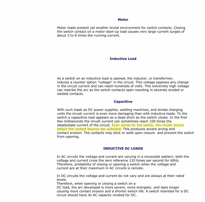
Motor
Motor loads present yet another brutal environment for switch contacts. Closingthe switch contact on a motor start-up load causes very large current surges ofabout 3 to 8 times the running current.
Inductive Load
As a switch on an inductive load is opened, the inductor, or transformer,induces a counter option "voltage" in the circuit. This voltage opposes any changein the circuit current and can reach hundreds of volts. This extremely high voltagecan restrike the arc as the switch contacts open resulting in severely eroded orwelded contacts.
Capacitive
With such loads as DC power supplies, welding machines, and strobe chargingunits the inrush current is even more damaging than with inductive loads. To theswitch a capacitive load appears as a dead short as the switch closes. In the firstfew milliseconds the inrush current can sometimes reach 100 times thesteadystate current of the circuit. Even worse for the switch, this inrush occursbefore the contact bounce has subsided. This produces severe arcing andcontact erosion. The contacts may stick or weld upon closure and prevent the switchfrom opening.
INDUCTIVE DC LOADS
In AC circuits the voltage and current are varying in a sinusoidal pattern; both thevoltage and current cross the zero reference 120 times per second for 60Hz.Therefore, probability of closing or opening a switch when the voltage andcurrent are at their maximum in AC circuits is remote.
In DC circuits the voltage and current do not vary and are always at their ratedlevels.Therefore, when opening or closing a switch on aDC load, the arc developed is more severe, more energetic, and lasts longercausing more contact erosion and a shorter switch life. A switch intended for a DCcircuit should have its AC capacity rerated for DC.
DESIGN FOR INDUCTIVE DC LOAD
Bar magnets are placed at each end of high capacity switches, and their magneticfield opposes the field created by the arcing current, thereby extinguishing thearc and protecting the contacts. Positive (+) must be connected to end terminalsand negative (-) to common terminals.
Robert
Even
Robert
worse
Robert
for
Robert
the
Robert
switch,
Robert
this
Robert
inrush
Robert
occurs
Robert
before
Robert
the
Robert
contact
Robert
bounce
Robert
has
Robert
subsided.

NKK Switches | 2004 http://www.nkkswitches.com/electrical.asp
TV RATINGS
The TV5 and TV8 ratings are tested and assigned by the Underwriters Laboratory.The switches are intended to be used as "Power ON" devices in equipment where ahigh tungsten inrush current is anticipated, such as tungsten-filament lamp loadsor entertainment equipment like sound systems and monitors.An example is the TV8 test which consists of an overload test and an endurancetest. The overload test consists of a switch closing on a minimum inrush currentof163 amps with 50 consecutive operations at a rate of 10 cycles per minute. Thetest must be conducted without any failures. In the endurance test the current isreduced to 117 amps, and the same switch is subjected to another 25,000operations.
In addition to electrical testing, the switch enclosure (housing) must comply withthe requirements for classifying materials as UL94V-0. The insulation materialmust have arc-tracking characteristics with a minimum arcing time of 180 secondswhen tested in accordance with the Standard Test Methods for High-Voltage,Low-Current Arc Resistance of Solid Electrical Insulation.
OPERATING RANGE
Three contact materials are commonly used in switches: gold, silver, andgold over silver. These materials give the options of low level, power level, pluscombined power and low level ratings.
Low Level ~ 0.4VA maximum @ 20V AC or DC maximum
Gold plated contacts are recommended for dry circuits, which are defined asvery low energy. In circuits where the voltage is below 28 volts DC and currentis below 100 milliamps (dry circuits), no arc develops as the contacts open orclose. So, the tarnish remains. Eventually without the arc, the contacts becomeso encrusted that the switch is unable to close the circuit due to the highcontact resistance. The solution to this is plating the silver contacts with gold,
NKK Switches | 2004 http://www.nkkswitches.com/electrical.asp
4 of 5 9/5/2004 12:03 PM
which does not tarnish. Gold plated contacts close under low voltage and lowcurrent conditions indefinitely, or for the mechanical life of the switch.
Power Level ~ 100mA to 10 amps @ 125V AC
Silver contacts are recommended for electrical levels above 0.4VA. Althoughsilver tarnishes, it is a good conductor and this electrical energy is sufficient tobreak through the tarnish to give reliable performance. The oxidation whichcoats the contact surfaces with a hard layer of insulative contamination isremoved by arcing. In circuits where the voltage is above about 12 volts DCand the current above .5 amps, an arc develops during opening or closing ofthe contacts. This arc keepsthe oxidation cleaned off.
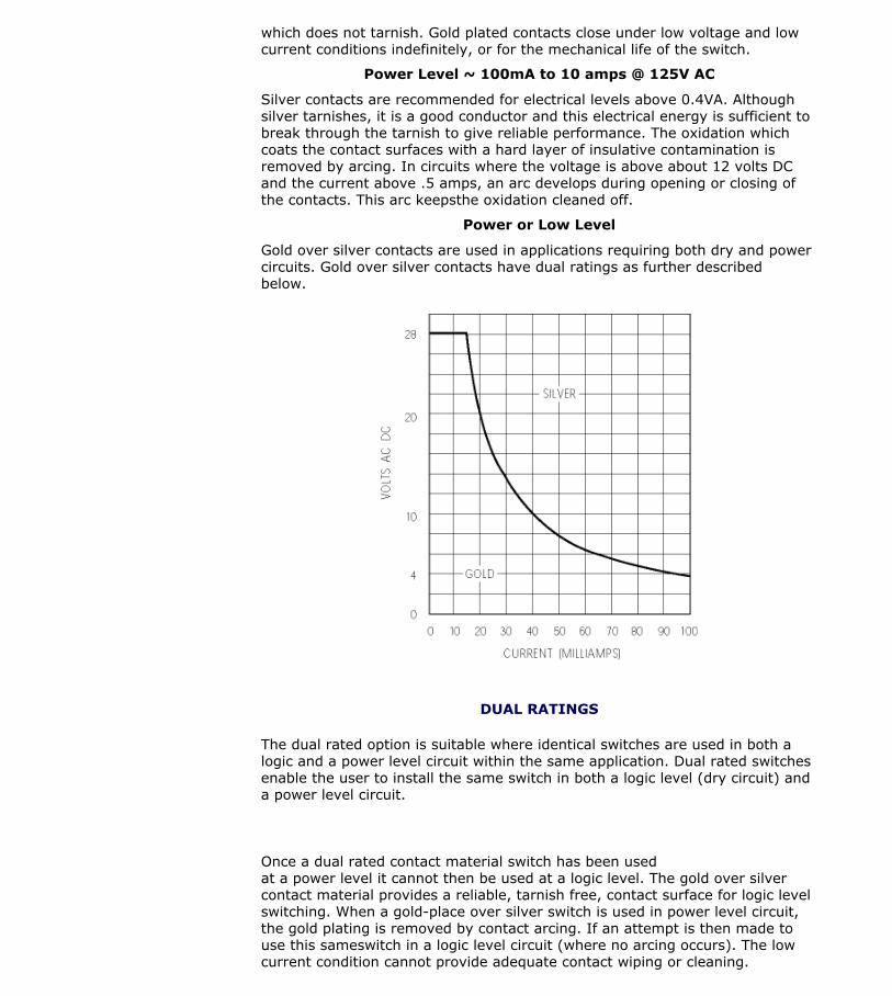
Power or Low Level
Gold over silver contacts are used in applications requiring both dry and powercircuits. Gold over silver contacts have dual ratings as further describedbelow.
DUAL RATINGS
The dual rated option is suitable where identical switches are used in both alogic and a power level circuit within the same application. Dual rated switchesenable the user to install the same switch in both a logic level (dry circuit) anda power level circuit.
Once a dual rated contact material switch has been usedat a power level it cannot then be used at a logic level. The gold over silvercontact material provides a reliable, tarnish free, contact surface for logic levelswitching. When a gold-place over silver switch is used in power level circuit,the gold plating is removed by contact arcing. If an attempt is then made touse this sameswitch in a logic level circuit (where no arcing occurs). The lowcurrent condition cannot provide adequate contact wiping or cleaning.
PRIVACY | LEGAL | CONTACT WEBMASTER | PARTNERS