SWITCH DISCONNECTORS - Lovato Electric
10
SWITCH DISCONNECTORS GL SERIES
Transcript of SWITCH DISCONNECTORS - Lovato Electric
S W I T C HD I S C O N N E C T O R S
GL SERIES
2
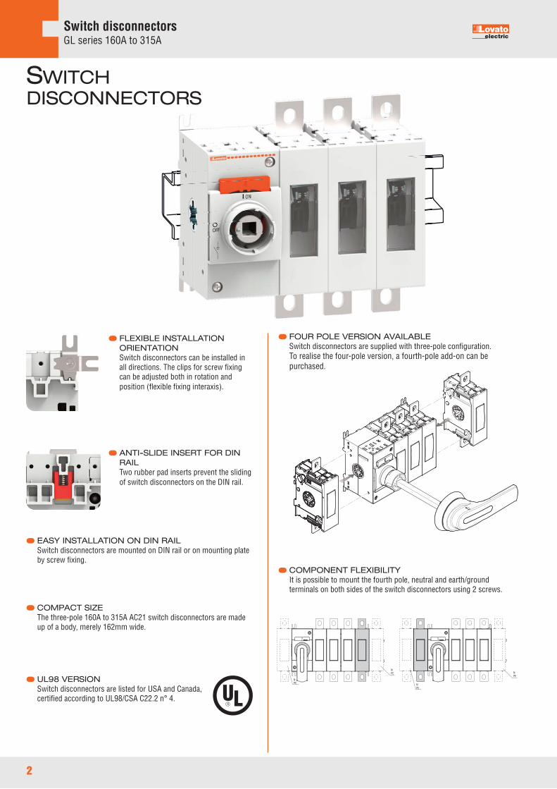
Switch disconnectorsGL series 160A to 315A
COMPACT SIZEThe three-pole 160A to 315A AC21 switch disconnectors are madeup of a body, merely 162mm wide.
EASY INSTALLATION ON DIN RAILSwitch disconnectors are mounted on DIN rail or on mounting plateby screw fixing.
UL98 VERSIONSwitch disconnectors are listed for USA and Canada,certified according to UL98/CSA C22.2 n° 4.
FOUR POLE VERSION AVAILABLESwitch disconnectors are supplied with three-pole configuration.To realise the four-pole version, a fourth-pole add-on can bepurchased.
COMPONENT FLEXIBILITYIt is possible to mount the fourth pole, neutral and earth/groundterminals on both sides of the switch disconnectors using 2 screws.
ANTI-SLIDE INSERT FOR DINRAILTwo rubber pad inserts prevent the slidingof switch disconnectors on the DIN rail.
FLEXIBLE INSTALLATIONORIENTATIONSwitch disconnectors can be installed inall directions. The clips for screw fixingcan be adjusted both in rotation andposition (flexible fixing interaxis).
SWITCHDISCONNECTORS
NPE
NPE
NPE
NPE

3
Switch disconnectorsGL series 160A to 315A
IP66 AND NEMA 4X HANDLESA wide range of screw fixing pistol grip handles is available withthe maximum degree of protection on the market.
UL508A HANDLE VERSIONIn compliance with UL508A standards, which require internalpanel inspection by authorized personnel with power applied,pistol handles are available with defeatable feature of the doorcoupling when the switch disconnector or the changeover switchis closed, i.e. in ON position.
WIDE RANGE OF ACCESSORIESA wide choice of auxiliary contacts, terminal covers, phasebarriers, terminal clamps, bridging bars, shafts and handles areavailable to satisfy every installation need.
HIGH IEC ELECTRICAL CAPABILITYThe rated currents in AC23 up to 250A - 690VAC are the highest ofthe category.
HANDLESSwitch disconnectors and changeover switches are standardsupplied without any handles.By purchasing the direct handle separately it is possible to realisethe direct operating version.By purchasing a shaft extension and a door coupling handleseparately it is possible to realise the door coupling version.
SHAFT MOUNTINGShafts can be mounted and removed very easily by snapping onthe front of the switch. This feature allows fast installation andeasy accessibility to the panel in case of maintenance.
ADD-ON AUXILIARY CONTACTSThe same add-on block is suitable for all the switch disconnectorsand changeover switches. Contacts are mounted on mainswitching actuator (max 8 contacts).
PADLOCKABLE HANDLESAll direct and door coupling handles are equipped with integratedpadlock mechanism.
VISIBLE CONTACTSThanks to the window on the individual power poles the open orclosed switch status is clearly visible at a distance.
4 Accessoriespages 5 and 6
Technical characteristicspage 9
Wiring diagramspage 8
Dimensionspages 7 and 8
Switch disconnectorsGL series 160A to 315A
General characteristics– 160 to 315A AC21 versions– 200A general purpose according to UL98– Compact dimensions and add-on fourth-pole– Screw or 35mm DIN rail fixing– Possibility to adjust the position of the clips for screw
fixing on plate– Visible contacts– Maximum number of power poles: 4.
Operational characteristics– Rated insulation voltage Ui: 1,000V– Rated impulse withstand Uimp: 12kV– Mechanical life: • 20,000 cycles.
Certifications and complianceCertifications obtained: cULus according to UL98 / CSA C22.2 n°4 for GL...UL and GLX42...UL types.Compliant with standards: IEC/EN 60947-3, IEC/EN 60947-1.
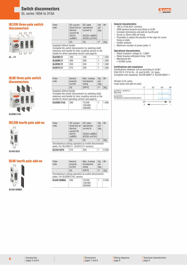
Order IEC conven- IEC rated Qty Wt code tional free air operational per thermal current Ie pkg current Ith AC21A AC22A (≤690V) (≤690V) AC23A (≤415V) [A] [A] n° [kg] Supplied without handle. Complete the switch disconnector by selecting shaft extension and handle for door coupling version or the handle for direct operating version (see page 6). GL0160 C1 160 160 1 1.500 GL0200 C1 200 200 1 1.500 GL0250 C1 250 250 1 1.500 GL0315 C1 315 250 1 1.500
Order General Max. 3-phase Qty Wt code purpose horsepower per current rating pkg [A] [HP/V] n° [kg] Supplied without handle. Complete the switch disconnector by selecting shaft extension and handle for door coupling version or the handle for direct operating version (see page 6). GL0200 C1UL 200 75/240 1 1.600 150/480 200/600
IEC/EN three-pole switchdisconnectors
Order IEC conven- IEC rated Qty Wt code tional free air operational per thermal current Ie pkg current Ith AC21A AC22A (≤690V) (≤690V) AC23A (≤415V) [A] [A] n° [kg] Simultaneous closing operation as switch disconnector poles. For GL0160 C1...GL0315 C1 versions. GLX42 0315 315 250 1 0.200
IEC/EN fourth pole add-on
UL98 three-pole switchdisconnectors
Order General Max. 3-phase Qty Wt code purpose horsepower per current rating pkg [A] [HP/V] n° [kg] Simultaneous closing operation as switch disconnector poles. For GL0200 C1UL version. GLX42 0200UL 200 75/240 1 0.200 150/480 200/600
UL98 fourth pole add-on
Strokes of GL poles (main poles and add-on pole)
0° 30° 60° 90°
OFF ONO I
GL0160 C1...GL0315 C1Main poles
GLX42 0315Simultaneous closing fourth pole add-on
GL...C1
GL0200 C1UL
GLX42 0315
GLX42 0200UL
5Accessoriespages 5 and 6
Technical characteristicspage 9
Wiring diagramspage 8
Dimensionspages 7 and 8
Switch disconnectorsGL series 160A to 315AAccessories
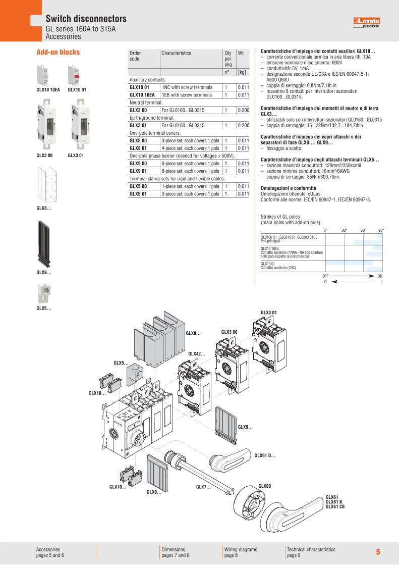
Caratteristiche d’impiego dei contatti ausiliari GLX10...– corrente convenzionale termica in aria libera Ith: 10A– tensione nominale d’isolamento: 690V– conduttività: 5V, 1mA– designazione secondo UL/CSA e IEC/EN 60947-5-1: A600 Q600– coppia di serraggio: 0,8Nm/7,1lb.in– massimo 8 contatti per interruttori sezionatori
GL0160...GL0315.
Caratteristiche d’impiego dei morsetti di neutro e di terraGLX3...– utilizzabili solo con interruttori sezionatori GL0160...GL0315– coppia di serraggio: 15...22Nm/132,7...194,7lbin.
Caratteristiche d’impiego dei copri attacchi e deiseparatori di fase GLX8..., GLX9...– fissaggio a scatto.
Caratteristiche d’impiego degli attacchi terminali GLX5...– sezione massima conduttori: 120mm2/250kcmil– sezione minima conduttori: 16mm2/6AWG– coppia di serraggio: 35Nm/309,7lbin.
Omologazioni e conformitàOmologazioni ottenute: cULusConformi alle norme: IEC/EN 60947-1, IEC/EN 60947-3.
Add-on blocks Order Characteristics Qty Wt code per pkg n° [kg] Auxiliary contacts. GLX10 01 1NC with screw terminals 1 0.011 GLX10 10EA 1EB with screw terminals 1 0.011 Neutral terminal. GLX3 00 For GL0160...GL0315 1 0.200 Earth/ground terminal. GLX3 01 For GL0160...GL0315 1 0.200 One-pole terminal covers. GLX8 00 3-piece set, each covers 1 pole 1 0.011 GLX8 01 4-piece set, each covers 1 pole 1 0.011 One-pole phase barrier (needed for voltages > 500V). GLX9 00 6-piece set, each covers 1 pole 1 0.011 GLX9 01 8-piece set, each covers 1 pole 1 0.011 Terminal clamp sets for rigid and flexible cables. GLX5 00 1-piece set, each covers 1 pole 1 0.011 GLX5 01 3-piece set, each covers 1 pole 1 0.011
Strokes of GL poles(main poles with add-on pole)
0° 30° 60° 90°
OFF ONO I
GL0160 C1...GL0315 C1, GL0200 C1ULPoli principali
GLX10 10EAContatto ausiliario (1NAA - NA con aperturaanticipata rispetto ai poli principali)
GLX10 01Contatto ausiliario (1NC)
GLX8...
GLX9...
GLX5...
GLX3 00
GLX10 10EA GLX10 01
GLX3 01
GLX10...
GLX5...
GLX10...
GLX8...
GLX7...
GLX9...
GLX42...
GLX3 00
GLX3 01
GLX61 D...
GLX61GLX61 BGLX61 CB
GLX9...GLX00
6 Wiring diagramspage 8
Dimensionspages 7 and 8
Switch disconnectorsGL series 160A to 315AAccessories
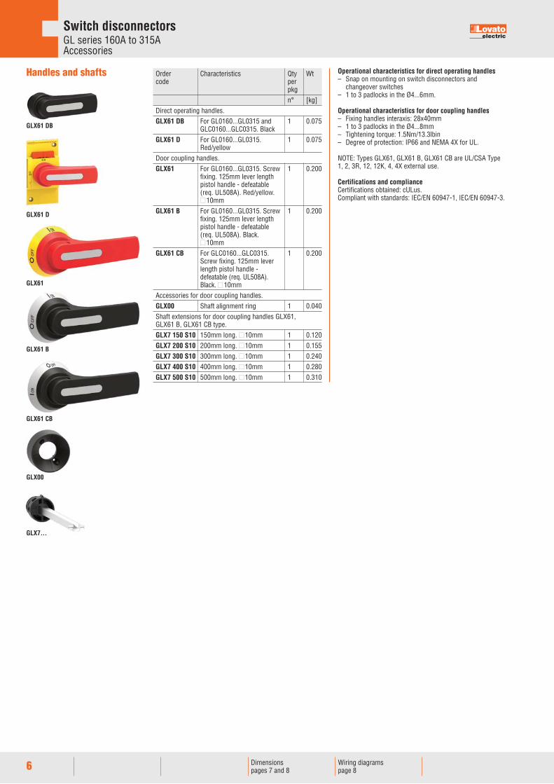
Operational characteristics for direct operating handles– Snap on mounting on switch disconnectors and
changeover switches– 1 to 3 padlocks in the Ø4...6mm.
Operational characteristics for door coupling handles– Fixing handles interaxis: 28x40mm– 1 to 3 padlocks in the Ø4...8mm– Tightening torque: 1.5Nm/13.3lbin– Degree of protection: IP66 and NEMA 4X for UL.
NOTE: Types GLX61, GLX61 B, GLX61 CB are UL/CSA Type1, 2, 3R, 12, 12K, 4, 4X external use.
Certifications and complianceCertifications obtained: cULus.Compliant with standards: IEC/EN 60947-1, IEC/EN 60947-3.
Handles and shafts Order Characteristics Qty Wt code per pkg n° [kg] Direct operating handles. GLX61 DB For GL0160...GL0315 and 1 0.075 GLC0160...GLC0315. Black GLX61 D For GL0160...GL0315. 1 0.075 Red/yellow Door coupling handles. GLX61 For GL0160...GL0315. Screw 1 0.200 fixing. 125mm lever length pistol handle - defeatable (req. UL508A). Red/yellow. �10mm GLX61 B For GL0160...GL0315. Screw 1 0.200 fixing. 125mm lever length pistol handle - defeatable (req. UL508A). Black. �10mm GLX61 CB For GLC0160...GLC0315. 1 0.200 Screw fixing. 125mm lever length pistol handle - defeatable (req. UL508A). Black. �10mm Accessories for door coupling handles. GLX00 Shaft alignment ring 1 0.040 Shaft extensions for door coupling handles GLX61, GLX61 B, GLX61 CB type. GLX7 150 S10 150mm long. �10mm 1 0.120 GLX7 200 S10 200mm long. �10mm 1 0.155 GLX7 300 S10 300mm long. �10mm 1 0.240 GLX7 400 S10 400mm long. �10mm 1 0.280 GLX7 500 S10 500mm long. �10mm 1 0.310
GLX00
GLX61
GLX61 B
GLX61 CB
GLX61 D
GLX61 DB
GLX7...
7
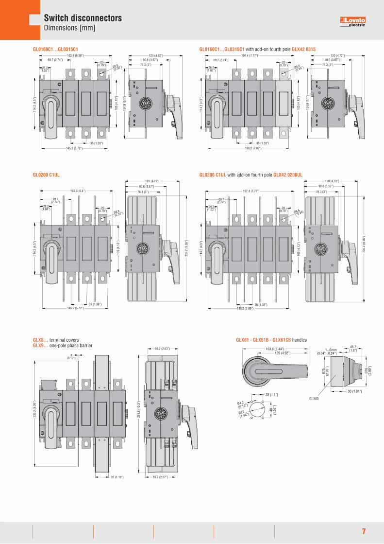
Switch disconnectorsDimensions [mm]
GL0160C1...GL0315C1162.3 (6.39”) 120 (4.72”)
154.
9 (6
.1”)
26.2(1.03”)
69.7 (2.74”)
35 (1.38”)
20(0.79”)
114.
2 (4
.5”)
145.2 (5.72”)
76.3 (3”)
90.6 (3.57”)
Ø8.6(0.34”)
105
(4.1
3”)
GL0160C1...GL0315C1 with add-on fourth pole GLX42 0315
26.2(1.03”)
69.7 (2.74”)197.4 (7.77”)
35 (1.38”)
180.2 (7.09”)
105
(4.1
3”)
76.3 (3”)
120 (4.72”)90.6 (3.57”)
154.
9 (6
.1”)
114.
2 (4
.5”)
20(0.79”)
Ø8.6(0.34”)
GL0200 C1UL
162.3 (6.4”)23
5.2
(9.2
6”)
120 (4.72”)
Ø8.6(0.34”)
105
(4.1
3”)
145.2 (5.72”)
114.
2 (4
.5”)
90.6 (3.57”)
20(0.79”)
35 (1.38”)
26.2(1.04”)
69.7(2.74”)
76.3 (3”)
GL0200 C1UL with add-on fourth pole GLX42 0200UL
114.
2 (4
.5”)
26.2(1.03”)
69.7(2.74”)
197.4 (7.77”)
20(0.79”) Ø8.6
(“0.34)
105
(4.1
3”)
180.2 (7.09”)35 (1.38”)
235.
2 (9
.26”
)
76.3 (3”)
120 (4.72”)
90.6 (3.57”)
GLX8... terminal coversGLX9... one-pole phase barrier
235.
2 (9
.26”
)
3(0.12”)
30 (1.18”)
66,7
65.2 (2.57”)
261.
6 (1
0.3”
)
66.7 (2.63”)
GLX61 - GLX61B - GLX61CB handles
163.6 (6.44”)125 (4.92”)
45.7(1.8”)
Ø4.2(0.16”)
Ø75
(2.9
5”)
Ø76
(2.9
9”)
30 (1.81”)28 (1.1”)
Ø37(1.46”)
40(1
.57”
)
1...6mm(0.04”...0.24”)
GLX00

8
Switch disconnectorsDimensions [mm]Wiring diagrams
GLX7... shaft extensions for door coupling handles
1...6(0.04”...0.24”)
Ø76
(2.9
9”)
30(1.18”)
45.7(1.8”)
125
(4.9
2”)
A
min 124 - shaft 80 (min 4.88” - shaft 3.15”) A [mm]GLX7...S10
min maxGLX7150S10 124...194GLX7200S10 124...244GLX7300S10 124...344GLX7400S10 124...444GLX7500S10 124...544
Three-pole GL0160...GL0315...
GL SERIES 160A TO 315A SWITCH DISCONNECTORS
L1 L2
T1 T2
L3
T3
LINE
LOAD
Fourth poleGLX42...
7 L4Line
Load
8 T4
7 L4
8 T4
ADD-ON BLOCKS AND ACCESSORIESAuxiliary contactsGLX10 10EA GLX10 01
7
8
1
2
Neutral terminalGLX3 00
N
N
Earth/Ground terminalGLX3 01
PE
PE

9
Switch disconnectorsTechnical characteristicsSwitch disconnectors
TECHNICAL DATA ACCORDING TO IEC/EN 60947TYPE 3-pole GL0160... GL0200... / GL0200...UL GL0250... GL0315... 4-pole GLX42 0315CONTACT CHARACTERISTICSIEC conventional free air A 160 200 250 315thermal current Ith (≤40°C)IEC rated insulation voltage V 1000UiIEC rated impulse kV 12withstand Uimp IEC rated operational current Ie AC21A 400V A 160 200 250 315 500V A 160 200 250 315 690V A 160 200 250 315AC22A 400V A 160 200 250 315 500V A 160 200 250 315 690V A 160 200 250 315AC23A 400V A 160 200 250 250 500V A 160 200 250 250 690V A 160 200 250 250Power dissipation W/pole 3.2 4 6.5 6.5IEC rated operational power AC23A 400V kW 90 110 140 140 690V kW 144 200 250 250IEC reactive power for control kvar 80 100 115 145of capacitors 400V SHORT CIRCUIT PROTECTION Rated short-time kA rms 8current (1s) Icw Conditional short-circuit kA rms 100current With fuse class gG A 160 200 250 315Making capacity AC23A 400V A 1600 2000 2500 2500Breaking capacity AC23A 400V A 1280 1600 2000 2000Mechanical life cycles 20000 Terminal for busbars mm M8 x 25 Tightening torque Nm 15...22 lbin 132...194 Conductor section min. mm2 70 95 120 185 AWG/ 00 000 250 400 KcmilAMBIENT CONDITIONS Temperature Operating °C -25...+55 Storage °C -40...+70Maximum altitude m 3000Mounting Normal Verticalposition Admissible AnyFixing By screw or on 35mm DIN rail (IEC/EN 60715)
TECHNICAL DATA ACCORDING TO UL/CSA RATINGSTYPE 3-pole — GL0200...UL — — 4-pole — GLX42 0200UL — —Compliance — UL98 — — CSA C22.2 N°4General purpose A — 200 — —current ratingsMax operating voltage V — 600 — —Horsepower ratings /motor FLAcurrent three-phase 240V HP/A — 75/192 — — 480V HP/A — 150/180 — — 600V HP/A — 200/192 — —Short circuit ratings KA rms — 200 — —With fuse class J A — 200 — —Terminal kit lugs — GLX5... — —Minimum enclosure mm — 400 x 250 x 150 — —dimensions at rated current

The
prod
ucts
des
crib
ed in
this
pub
licat
ion
are
subj
ect t
o be
revi
sed
or im
prov
ed a
t any
mom
ent.
Cata
logu
e de
scrip
tions
and
deta
ils, s
uch
as te
chni
cal a
nd o
pera
tiona
l dat
a, d
raw
ings
, dia
gram
s an
d in
stru
ctio
ns, e
tc.,
do n
ot h
ave
any
cont
ract
ual v
alue
. In
add
ition
, pro
duct
s sh
ould
be
inst
alle
d an
d us
ed b
y qu
alifi
ed p
erso
nnel
and
in c
ompl
ianc
e w
ith th
e re
gula
tions
in fo
rce
for
elec
trica
l sys
tem
s in
ord
er to
avo
id d
amag
es a
nd s
afet
y ha
zard
s.
LOVATO ELECTRIC S.P. A.
via Don E. Mazza, 1224020 Gorle (Bergamo) Italy
Tel +39 035 [email protected]
www.LovatoElectric.com
Follow us
PD12
4 GB
05
18
LOVATO ELECTRIC LTD Lovato House - Providence Drive LyeSTOURBRIDGEWest Midlands - DY9 8HQ - ENGLAND Tel. +44 01384 [email protected]
LOVATO ELECTRIC GmbH Im Ermlisgrund 30 76337 WALDBRONNGERMANY Tel. +49 7243 766 937 0 [email protected] www.LovatoElectric.de
LOVATO ELECTRIC SP. Z O.O.ul. Zachodnia 355-330 Błonie k.WrocławiaPOLANDTel. +48 71 [email protected]
ООО Ловато Электрик107023, г
.19, 2,RUSSIA
: +7 (495) [email protected]
LOVATO ELECTRIC CORPORATION4500, Garand StreetLaval, Quebec CANADAH7L 5Z6Tel. [email protected]
LOVATO ELECTRIC S.L.U Pol. Ind. Llinars Park C/. de la TecnologÍa, 102Passatge B, Nau 908450 LLINARS DEL VALLÈS - SPAINTel. +34 93 [email protected] www.LovatoElectric.es
LOVATO ELEKTRIK LTDAraylar Sanayi SitesiNo:9A/36 Özvatan CaddesiTepeören Mahallesi 34959 TuzlaIstanbul,TURKEYTel. +90 216 499 86 [email protected]
LOVATO ELECTRIC CO LTDShanghai, CHINA上海市虹井路288号燎申虹桥国际中心B座701单元邮编:201103电话:+86 021 [email protected]
LOVATO ELECTRIC INC 2017 Georgetown Blvd.CHESAPEAKE,VA 23325UNITED STATESTel. +1 757 [email protected]
LOVATO ELECTRIC. S.R.O.Cizovska 488397 01 PISEKCZECH REPUBLIC Tel. +420 226 203210 [email protected] www.LovatoElectric.cz
LOVATO ELECTRIC ME FZE#A101-9, First Floor, Block ADSO-Operations and Facility CentreDUBAI SILICON OASISDubai, UAETel. +971 4 371 [email protected] www.LovatoElectric.ae
LOVATO ELECTRIC SASIMMEUBLE DANICA B21 Avenue Georges PompidouFRANCETel. +33 4 72 91 31 [email protected]
LOVATO ELECTRIC SRLMuntenia Business Center,Splaiul Unirii nr. 16, et. 6, cam. 601RO-040035, sector 4,Bucarest, ROMANIATel. +40 372 074 [email protected]