![Terofox pneumatic actuator catalogue [act c201601-m(b)]](https://static.fdocuments.in/doc/165x107/58ef99961a28abf5718b466f/terofox-pneumatic-actuator-catalogue-act-c201601-mb.jpg)
Switch Actuator Modules for the Room Controller, …...Switch Actuator Modules for the Room...
100
ABB i-bus ® KNX Switch Actuator Modules for the Room Controller, SA/M, ES/M Product Manual
Transcript of Switch Actuator Modules for the Room Controller, …...Switch Actuator Modules for the Room...

ABB i-bus® KNX Switch Actuator Modules for the Room Controller, SA/M, ES/M Product Manual

2
ABB i-bus® KNX Contents
SA/M ES/M | 2CDC 514 055 D0201…i
Contents Page
1 General ................................................................................................. 3
1.1 Product and functional overview...................................................................................................3 1.2 Using the product manual.............................................................................................................3 1.3 Note..............................................................................................................................................4
2 Device Technology .............................................................................. 5
2.1 SA/M 2.6.1, Switch Actuator Module, 2-fold, 6 AX........................................................................5 2.1.1 Technical data ..............................................................................................................................5 2.1.2 Lamp loads at 230 V AC...............................................................................................................6 2.1.3 Circuit diagram SA/M 2.6.1...........................................................................................................7 2.1.4 Description of the outputs.............................................................................................................7 2.1.5 Assembly and installation .............................................................................................................7 2.2 SA/M 2.6.1 Switch Actuator Module, 2-fold, 16 A, floating ...........................................................8 2.2.1 Technical data ..............................................................................................................................8 2.2.2 Lamp loads at 230 V AC...............................................................................................................9 2.2.3 Circuit diagram SA/M 2.16.1.......................................................................................................10 2.2.4 Description of the outputs...........................................................................................................10 2.2.5 Assembly and installation ...........................................................................................................10 2.3 ES/M 2.230.1 Electronic Switch Actuator Module, 2-fold, 230 V ................................................11 2.3.1 Technical data ............................................................................................................................11 2.3.2 Circuit diagram ES/M 2.230.1.....................................................................................................12 2.3.3 Description of the outputs...........................................................................................................12 2.3.4 Assembly and installation ...........................................................................................................12 2.4 ES/M 2.24.1 Electronic Switch Actuator Module, 2-fold, 24 V ....................................................13 2.4.1 Technical data ............................................................................................................................13 2.4.2 Circuit diagram ES/M 2.230.1.....................................................................................................15 2.4.3 Description of the outputs...........................................................................................................15 2.4.4 Assembly and installation ...........................................................................................................15
3 Commissioning.................................................................................. 17
3.1 Overview ....................................................................................................................................17 3.2 Parameters .................................................................................................................................20 3.2.1 Parameter window A: General....................................................................................................20 3.3 Operating mode Switch Actuator ................................................................................................21 3.3.1 Parameter window A: General....................................................................................................21 3.3.2 Parameter window A: Function...................................................................................................23 3.3.3 Parameter window A: Time ........................................................................................................25 3.3.4 Parameter window A: Preset ......................................................................................................32 3.3.5 Parameter window A: Scene ......................................................................................................34 3.3.6 Parameter window A: Logic ........................................................................................................36 3.3.7 Parameter window A: Safety ......................................................................................................38 3.3.8 Parameter window A: Threshold.................................................................................................41 3.3.9 Brief overview of the communication objects..............................................................................43 3.3.10 Communication objects General.................................................................................................44 3.3.11 Communication objects Time, staircase lighting, flashing ..........................................................45 3.3.12 Communication objects Preset ...................................................................................................46 3.3.13 Communication objects Scene (8 bit) .........................................................................................47 3.3.14 Communication objects Connection/Logic..................................................................................48 3.3.15 Communication objects Priority/forced operation, cyclic monitoring ...........................................49 3.3.16 Communication objects Threshold value ....................................................................................49 3.4 Operating mode heating actuator ...............................................................................................50 3.4.1 Parameter window A: General....................................................................................................50 3.4.2 Parameter window A: Function...................................................................................................53 3.4.3 Parameter window A: Monitoring................................................................................................54 3.4.4 Parameter window A: Forced operation .....................................................................................55 3.4.5 Parameter window A: Valve Purge .............................................................................................56 3.4.6 Brief overview of the communication objects..............................................................................57
ABB i-bus® KNX Contents
ii SA/M ES/M | 2CDC 514 055 D0201
3.4.7 Communication objects ............................................................................................................. 58 3.5 Operating mode Fan coil control (blower convection unit) ......................................................... 60 3.5.1 What is a fan coil unit?............................................................................................................... 60 3.5.2 Parameter window A: General ................................................................................................... 61 3.5.3 Parameter window A: Speeds.................................................................................................... 63 3.5.4 Parameter window A: Function .................................................................................................. 64 3.5.5 Parameter window A: Monitoring ............................................................................................... 65 3.5.6 Parameter window A: Step limitation ......................................................................................... 67 3.5.7 Parameter window A: Forced operation..................................................................................... 68 3.5.8 Brief overview of the communication objects ............................................................................. 69 3.5.9 Communication objects Master.................................................................................................. 70 3.5.10 Communication objects Slave.................................................................................................... 72
4 Planning and application...................................................................73
4.1 The three operating modes........................................................................................................ 73 4.2 Operating mode Switch actuator................................................................................................ 74 4.2.1 Time functions ........................................................................................................................... 74 4.2.1.1 Staircase lighting function .......................................................................................................... 74 4.2.1.2 ON and OFF delay..................................................................................................................... 76 4.2.1.3 Flashing ..................................................................................................................................... 77 4.2.2 Function Logic ........................................................................................................................... 78 4.2.3 Function Preset.......................................................................................................................... 79 4.2.4 Function Scene.......................................................................................................................... 81 4.2.5 Function Threshold .................................................................................................................... 82 4.2.6 Function chart ............................................................................................................................ 83 4.3 Operating mode Heating actuator .............................................................................................. 84 4.4 Operating mode Fan coil control ................................................................................................ 86 4.4.1 Terms ........................................................................................................................................ 86 4.4.2 Configuration of a HVAC system with Fan Coil units ................................................................. 86 4.4.3 Design of a Fan Coil unit............................................................................................................ 87 4.4.4 Variants...................................................................................................................................... 88 4.4.5 Connection................................................................................................................................. 89 4.5 Reaction on voltage failure and recovery................................................................................... 91 4.6 Behaviour after programming .................................................................................................... 91
A Appendix.............................................................................................93
A.1 Table of values of communication object Status byte ................................................................ 93 A.2 Ordering Information.................................................................................................................. 94 A.3 Notes ......................................................................................................................................... 95 A.4 Notes ......................................................................................................................................... 96

ABB i-bus® KNX General
SA/M ES/M | 2CDC 514 055 D0201 3
1 General
1.1 Product and functional overview
The Switch Actuator Modules SA/M 2.6.1 and SA/M 2.16.1 as well as the Electronic Switch Actuator Modules ES/M 2.230.1 and ES/M 2.24.1 are snapped into a module slot of the Room Controller Basis Device RC/A. They are used to control switched loads:
Load type Suitable module type
Lighting SA/M
Electrothermal valve drives (heating control) ES/M
Blower convectors (Fan coil units) SA/M
Signalling equipment ES/M
The Room Controller Basis Device establishes the connection to the ABB i-bus® KNX installation bus.
All the modules have two outputs each. The Switch Actuator Modules SA/M switch via relay outputs while the Electronic Switch Actuator Modules ES/M switch via noise-free, wear-resistant electronic semiconductor components.
SA/M 2.6.1 and ES/M 2.230.1 are automatically connected to the incoming supply when they are snapped into the Room Controller Basis Device. The incoming supply of the SA/M 2.16.1 and the ES/M 2.24.1 should be connected directly to the modules.
On the output side the devices feature screw terminals.
The comprehensive functionality is defined by programming the Room Controller Basis Device with the ETS. It is almost identical for all three devices.
1.2 Using the product manual
This product manual provides you with detailed technical information relating to the device, its installation and programming. The application of the device is described using examples.
This manual is divided into the following sections:
Chapter 1 General
Chapter 2 Device technology
Chapter 3 Commissioning
Chapter 4 Planning and application
Chapter A Appendix
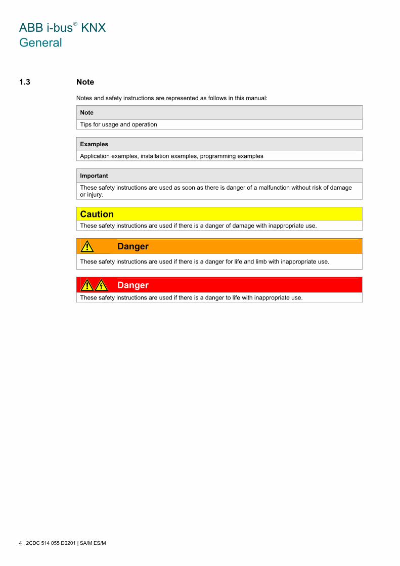
ABB i-bus® KNX General
4 2CDC 514 055 D0201 | SA/M ES/M
1.3 Note
Notes and safety instructions are represented as follows in this manual:
Note
Tips for usage and operation
Examples
Application examples, installation examples, programming examples
Important
These safety instructions are used as soon as there is danger of a malfunction without risk of damage or injury.
Caution These safety instructions are used if there is a danger of damage with inappropriate use.
Danger
These safety instructions are used if there is a danger for life and limb with inappropriate use.
Danger These safety instructions are used if there is a danger to life with inappropriate use.
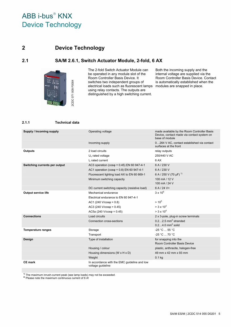
ABB i-bus® KNX Device Technology
SA/M ES/M | 2CDC 514 055 D0201 5
2 Device Technology
2.1 SA/M 2.6.1, Switch Actuator Module, 2-fold, 6 AX
The 2-fold Switch Actuator Module can be operated in any module slot of the Room Controller Basis Device. It switches two independent groups of electrical loads such as fluorescent lamps using relay contacts. The outputs are distinguished by a high switching current.
Both the incoming supply and the internal voltage are supplied via the Room Controller Basis Device. Contact is automatically established when the modules are snapped in place.
2.1.1 Technical data
Supply / Incoming supply Operating voltage made available by the Room Controller Basis Device, contact made via contact system on base of module
Incoming supply 0…264 V AC, contact established via contact surfaces at the front
Outputs 2 load circuits relay outputs
Un rated voltage 250/440 V AC
In rated current 6 AX
Switching currents per output AC3 operation (cosφ = 0.45) EN 60 947-4-1 6 A / 230 V
AC1 operation (cosφ = 0.8) EN 60 947-4-1 6 A / 230 V
Fluorescent lighting load AX to EN 60 669-1 6 A / 250 V (70 μF) 1)
Minimum switching capacity 100 mA / 12 V
100 mA / 24 V
DC current switching capacity (resistive load) 6 A / 24 V=
Output service life Mechanical endurance 3 x 10⁶
Electrical endurance to EN 60 947-4-1
AC1 (240 V/cosφ = 0.8) > 105
AC3 (240 V/cosφ = 0.45) > 3 x 10⁴
AC5a (240 V/cosφ = 0.45) > 3 x 10⁴
Connections Load circuits 2 x 3-pole, plug-in screw terminals
Connection cross-sections 0.2…2.5 mm2 stranded
0.2…4.0 mm2 solid
Temperature ranges Storage -25 °C ... 55 °C
Transport -25 °C ... 70 °C
Design Type of installation for snapping into the
Room Controller Basis Device
Housing / colour plastic, anthracite, halogen-free
Housing dimensions (W x H x D) 49 mm x 42 mm x 93 mm
Weight 0.1 kg
CE mark In accordance with the EMC guideline and low voltage guideline
1) The maximum inrush-current peak (see lamp loads) may not be exceeded. 2) Please note the maximum continuous current of 6 A!
2CD
C 0
71 0
09 F
0004

ABB i-bus® KNX Device Technology
6 2CDC 514 055 D0201 | SA/M ES/M
Device type Application program Maximum number of communication objects
Maximum number of group addresses
Maximum number of associations
RC/A 4.2 Room Controller modular 4f2/1.0 125 254 255
RC/A 8.1 Room Controller modular 8f/2.0 246 254 255
RC/A 8.2 Room Controller modular 8f2/1.0 245 254 255
Note
The ETS and the current version of the device application program are required for programming. The application program is available in the ETS at ABB/Room automation, Room Controller. The device does not support the closing function of a KNX device in the ETS. If you inhibit access to all devices of the project with a BCU code, it has no effect on this device. Reading out data and programming is still possible.
Important
Programming is possible only when the supply voltage is applied.
2.1.2 Lamp loads at 230 V AC
Lamps Incandescent lamp load 1380 W
Fluorescent lamps T5 / T8 Uncorrected 1380 W
Parallel compensated 1380 W
DUO circuit 1380 W
Low-volt halogen lamps Inductive transformer 1200 W
Electronic transformer 1380 W
Halogen lamps 230 V 1380 W
Dulux lamp Uncorrected 1100 W
Parallel compensated 1100 W
Mercury-vapour lamp Uncorrected 1380 W
Parallel compensated 1380 W
Switching capacity Max. peak inrush-current Ip (150 μs) 400 A
Max. peak inrush-current Ip (250 μs) 320 A
Max. peak inrush-current Ip (600 μs) 200 A
Number of electronic ballasts (T5/T8, single element)1)
18 W (ABB EVG 1 x 18 CF ) 23
24 W (ABB EVG-T5 1 x 24 CY) 23
36 W (ABB EVG 1 x 36 CF) 14
58 W (ABB EVG 1 x 58 CF) 11
80 W (Helvar EL 1 x 80 SC) 10 1) For multiple element lamps or other types the number of electronic ballasts must be determined using the peak inrush current of the electronic ballasts.
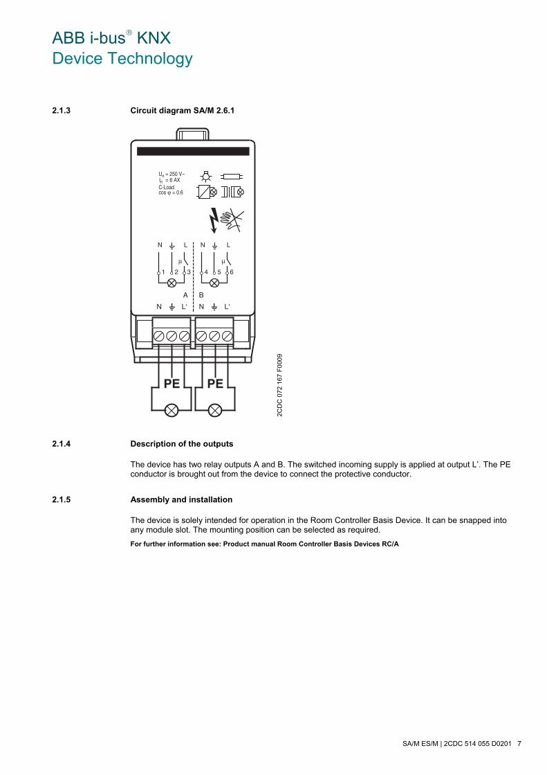
ABB i-bus® KNX Device Technology
SA/M ES/M | 2CDC 514 055 D0201 7
2.1.3 Circuit diagram SA/M 2.6.1
2.1.4 Description of the outputs
The device has two relay outputs A and B. The switched incoming supply is applied at output L’. The PE conductor is brought out from the device to connect the protective conductor.
2.1.5 Assembly and installation
The device is solely intended for operation in the Room Controller Basis Device. It can be snapped into any module slot. The mounting position can be selected as required.
For further information see: Product manual Room Controller Basis Devices RC/A
2CD
C 0
72 1
67 F
0009
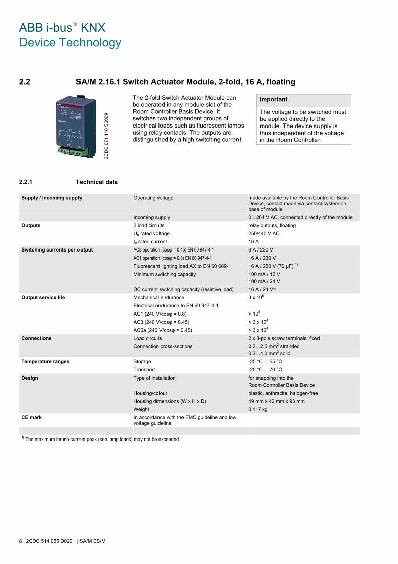
ABB i-bus® KNX Device Technology
8 2CDC 514 055 D0201 | SA/M ES/M
2.2 SA/M 2.16.1 Switch Actuator Module, 2-fold, 16 A, floating
The 2-fold Switch Actuator Module can be operated in any module slot of the Room Controller Basis Device. It switches two independent groups of electrical loads such as fluorescent lamps using relay contacts. The outputs are distinguished by a high switching current.
Important
The voltage to be switched must be applied directly to the module. The device supply is thus independent of the voltage in the Room Controller.
2.2.1 Technical data
Supply / Incoming supply Operating voltage made available by the Room Controller Basis Device, contact made via contact system on base of module
Incoming supply 0…264 V AC, connected directly of the module
Outputs 2 load circuits relay outputs, floating
Un rated voltage 250/440 V AC
In rated current 16 A
Switching currents per output AC3 operation (cosφ = 0.45) EN 60 947-4-1 8 A / 230 V
AC1 operation (cosφ = 0.8) EN 60 947-4-1 16 A / 230 V
Fluorescent lighting load AX to EN 60 669-1 16 A / 250 V (70 μF) 1)
Minimum switching capacity 100 mA / 12 V
100 mA / 24 V
DC current switching capacity (resistive load) 16 A / 24 V=
Output service life Mechanical endurance 3 x 10⁶
Electrical endurance to EN 60 947-4-1
AC1 (240 V/cosφ = 0.8) > 105
AC3 (240 V/cosφ = 0.45) > 3 x 10⁴
AC5a (240 V/cosφ = 0.45) > 3 x 10⁴
Connections Load circuits 2 x 3-pole screw terminals, fixed
Connection cross-sections 0.2…2.5 mm2 stranded
0.2…4.0 mm2 solid
Temperature ranges Storage -25 °C ... 55 °C
Transport -25 °C ... 70 °C
Design Type of installation for snapping into the
Room Controller Basis Device
Housing/colour plastic, anthracite, halogen-free
Housing dimensions (W x H x D) 49 mm x 42 mm x 93 mm
Weight 0.117 kg
CE mark In accordance with the EMC guideline and low voltage guideline
1) The maximum inrush-current peak (see lamp loads) may not be exceeded.
2CD
C 0
71 1
10 S
0009
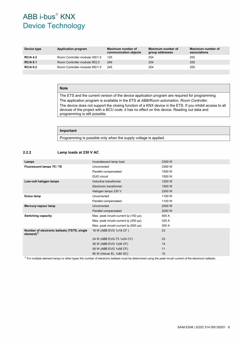
ABB i-bus® KNX Device Technology
SA/M ES/M | 2CDC 514 055 D0201 9
Device type Application program Maximum number of communication objects
Maximum number of group addresses
Maximum number of associations
RC/A 4.2 Room Controller modular 4f2/1.0 125 254 255
RC/A 8.1 Room Controller modular 8f/2.0 246 254 255
RC/A 8.2 Room Controller modular 8f2/1.0 245 254 255
Note
The ETS and the current version of the device application program are required for programming. The application program is available in the ETS at ABB/Room automation, Room Controller. The device does not support the closing function of a KNX device in the ETS. If you inhibit access to all devices of the project with a BCU code, it has no effect on this device. Reading out data and programming is still possible.
Important
Programming is possible only when the supply voltage is applied.
2.2.2 Lamp loads at 230 V AC
Lamps Incandescent lamp load 2300 W
Fluorescent lamps T5 / T8 Uncorrected 2300 W
Parallel compensated 1500 W
DUO circuit 1500 W
Low-volt halogen lamps Inductive transformer 1200 W
Electronic transformer 1500 W
Halogen lamps 230 V 2300 W
Dulux lamp Uncorrected 1100 W
Parallel compensated 1100 W
Mercury-vapour lamp Uncorrected 2000 W
Parallel compensated 2000 W
Switching capacity Max. peak inrush-current Ip (150 μs) 400 A
Max. peak inrush-current Ip (250 μs) 320 A
Max. peak inrush-current Ip (600 μs) 200 A
Number of electronic ballasts (T5/T8, single element)1)
18 W (ABB EVG 1x18 CF ) 23
24 W (ABB EVG-T5 1x24 CY) 23
36 W (ABB EVG 1x36 CF) 14
58 W (ABB EVG 1x58 CF) 11
80 W (Helvar EL 1x80 SC) 10 1) For multiple element lamps or other types the number of electronic ballasts must be determined using the peak inrush current of the electronic ballasts.
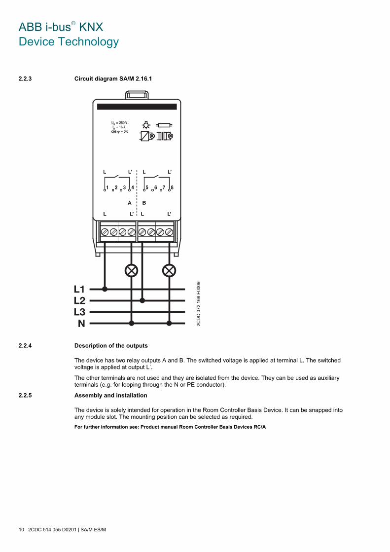
ABB i-bus® KNX Device Technology
10 2CDC 514 055 D0201 | SA/M ES/M
2.2.3 Circuit diagram SA/M 2.16.1
2.2.4 Description of the outputs
The device has two relay outputs A and B. The switched voltage is applied at terminal L. The switched voltage is applied at output L’.
The other terminals are not used and they are isolated from the device. They can be used as auxiliary terminals (e.g. for looping through the N or PE conductor).
2.2.5 Assembly and installation
The device is solely intended for operation in the Room Controller Basis Device. It can be snapped into any module slot. The mounting position can be selected as required.
For further information see: Product manual Room Controller Basis Devices RC/A
2CD
C 0
72 1
68 F
0009

ABB i-bus® KNX Device Technology
SA/M ES/M | 2CDC 514 055 D0201 11
2.3 ES/M 2.230.1 Electronic Switch Actuator Module, 2-fold, 230 V
The 2-fold Electronic Switch Actuator Module is snapped into any module slot of the Room Controller Basis Device. Using two semiconductor outputs, it switches two resistive loads such as electrothermal valve drives for heating control. The outputs are noise-free and wear-resistant. The nominal switching voltage is 115 or 230 V.
Both the incoming supply and the internal voltage are supplied via the Room Controller Basis Device. Contact is automatically established when the modules are snapped in place.
2.3.1 Technical data
Supply / Incoming supply Internal supply made available by the Room Controller Basis Device, contact made via contact system on the module base
Incoming supply 90…264 V AC / DC, contact established via contact surfaces at the front
Outputs 2 load circuits semiconductor outputs for resistive loads
inrush current: max. 1 A
continuous current: max. 700 mA
Connections Load circuits 2 x 3-pole, plug-in screw terminals
Connection cross-sections 0.2…2.5 mm2 stranded
0.2…4.0 mm2 solid
Temperature ranges Storage -25 °C ... 55 °C
Transport -25 °C ... 70 °C
Design Type of installation for snapping into the
Room Controller Basis Device
Housing / colour plastic, anthracite, halogen-free
Housing dimensions (W x H x D) 49 mm x 42 mm x 93 mm
Weight 0.08 kg
CE mark In accordance with the EMC guideline and low voltage guideline
Device type Application program Maximum number of
communication objects Maximum number of group addresses
Maximum number of associations
RC/A 4.2 Room Controller modular 4f2/1.0 125 254 255
RC/A 8.1 Room Controller modular 8f/2.0 246 254 255
RC/A 8.2 Room Controller modular 8f2/1.0 245 254 255
Note
The ETS and the current version of the device application program are required for programming. The application program is available in the ETS at ABB/Room automation, Room Controller. The device does not support the closing function of a KNX device in the ETS. If you inhibit access to all devices of the project with a BCU code, it has no effect on this device. Reading out data and programming is still possible.
Important
Programming is possible only when the supply voltage is applied.
2CD
C 0
71 1
32 F
0004
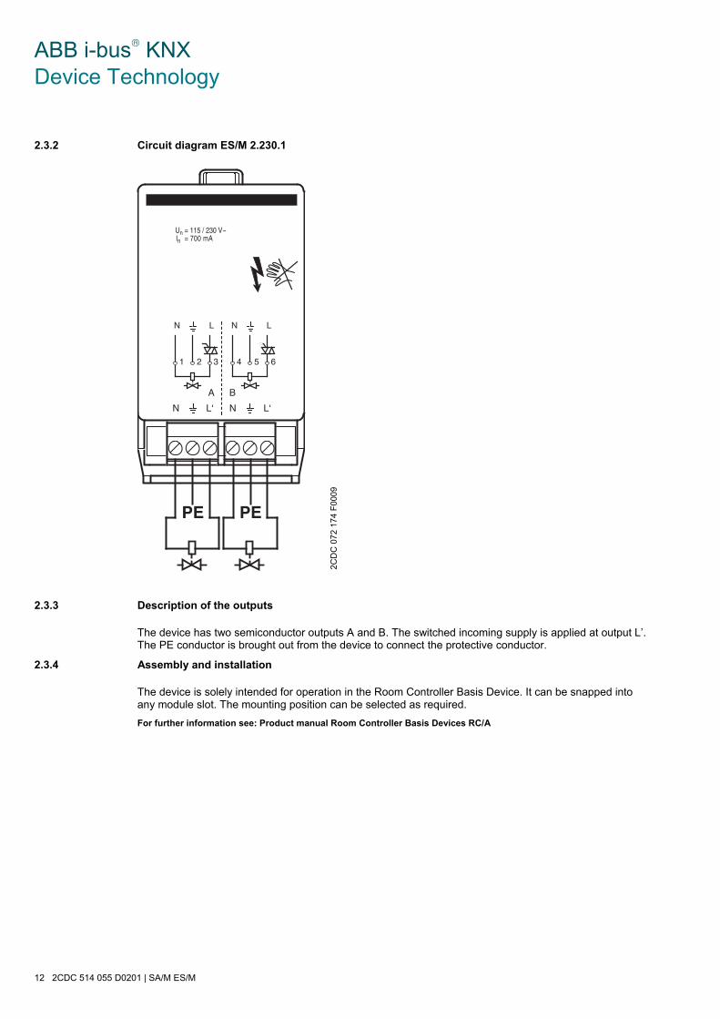
ABB i-bus® KNX Device Technology
12 2CDC 514 055 D0201 | SA/M ES/M
2.3.2 Circuit diagram ES/M 2.230.1
2.3.3 Description of the outputs
The device has two semiconductor outputs A and B. The switched incoming supply is applied at output L’. The PE conductor is brought out from the device to connect the protective conductor.
2.3.4 Assembly and installation
The device is solely intended for operation in the Room Controller Basis Device. It can be snapped into any module slot. The mounting position can be selected as required.
For further information see: Product manual Room Controller Basis Devices RC/A
2CD
C 0
72 1
74 F
0009
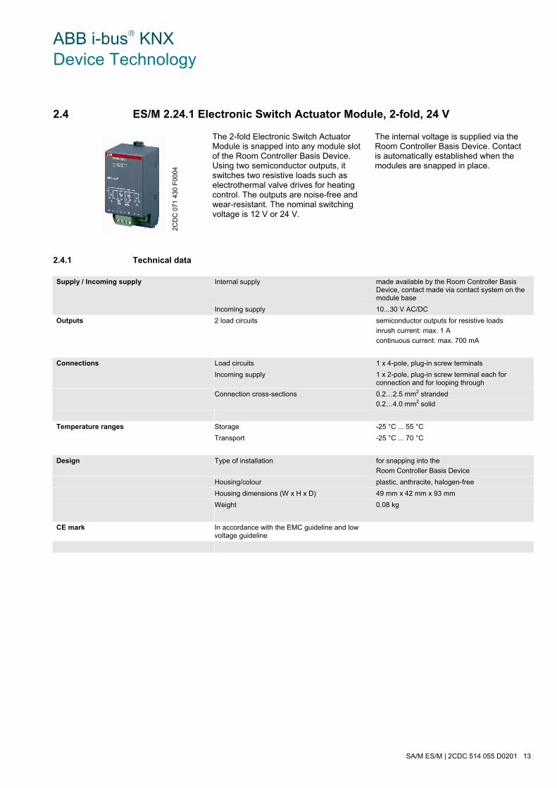
ABB i-bus® KNX Device Technology
SA/M ES/M | 2CDC 514 055 D0201 13
2.4 ES/M 2.24.1 Electronic Switch Actuator Module, 2-fold, 24 V
The 2-fold Electronic Switch Actuator Module is snapped into any module slot of the Room Controller Basis Device. Using two semiconductor outputs, it switches two resistive loads such as electrothermal valve drives for heating control. The outputs are noise-free and wear-resistant. The nominal switching voltage is 12 V or 24 V.
The internal voltage is supplied via the Room Controller Basis Device. Contact is automatically established when the modules are snapped in place.
2.4.1 Technical data
Supply / Incoming supply Internal supply made available by the Room Controller Basis Device, contact made via contact system on the module base
Incoming supply 10...30 V AC/DC
Outputs 2 load circuits semiconductor outputs for resistive loads
inrush current: max. 1 A
continuous current: max. 700 mA
Connections Load circuits 1 x 4-pole, plug-in screw terminals
Incoming supply 1 x 2-pole, plug-in screw terminal each for connection and for looping through
Connection cross-sections 0.2…2.5 mm2 stranded
0.2…4.0 mm2 solid
Temperature ranges Storage -25 °C ... 55 °C
Transport -25 °C ... 70 °C
Design Type of installation for snapping into the
Room Controller Basis Device
Housing/colour plastic, anthracite, halogen-free
Housing dimensions (W x H x D) 49 mm x 42 mm x 93 mm
Weight 0.08 kg
CE mark In accordance with the EMC guideline and low voltage guideline
2CD
C 0
71 4
30 F
0004

ABB i-bus® KNX Device Technology
14 2CDC 514 055 D0201 | SA/M ES/M
Device type Application program Maximum number of communication objects
Maximum number of group addresses
Maximum number of associations
RC/A 4.2 Room Controller modular 4f2/1.0 125 254 255
RC/A 8.1 Room Controller modular 8f/2.0 246 254 255
RC/A 8.2 Room Controller modular 8f2/1.0 245 254 255
Note
The ETS and the current version of the device application program are required for programming. The application program is available in the ETS at ABB/Room automation, Room Controller. The device does not support the closing function of a KNX device in the ETS. If you inhibit access to all devices of the project with a BCU code, it has no effect on this device. Reading out data and programming is still possible.
Important
Programming is possible only when the supply voltage is applied.

ABB i-bus® KNX Device Technology
SA/M ES/M | 2CDC 514 055 D0201 15
2.4.2 Circuit diagram ES/M 2.230.1
2.4.3 Description of the outputs
The output has two switched semiconductor outputs A and B. The incoming supply is fed or looped through to the next module via the terminals + and –.
2.4.4 Assembly and installation
The device is solely intended for operation in the Room Controller Basis Device. It can be snapped into any module slot. The mounting position can be selected as required.
For further information see: Product manual Room Controller Basis Devices RC/A
2CD
C 0
72 1
75 F
0009

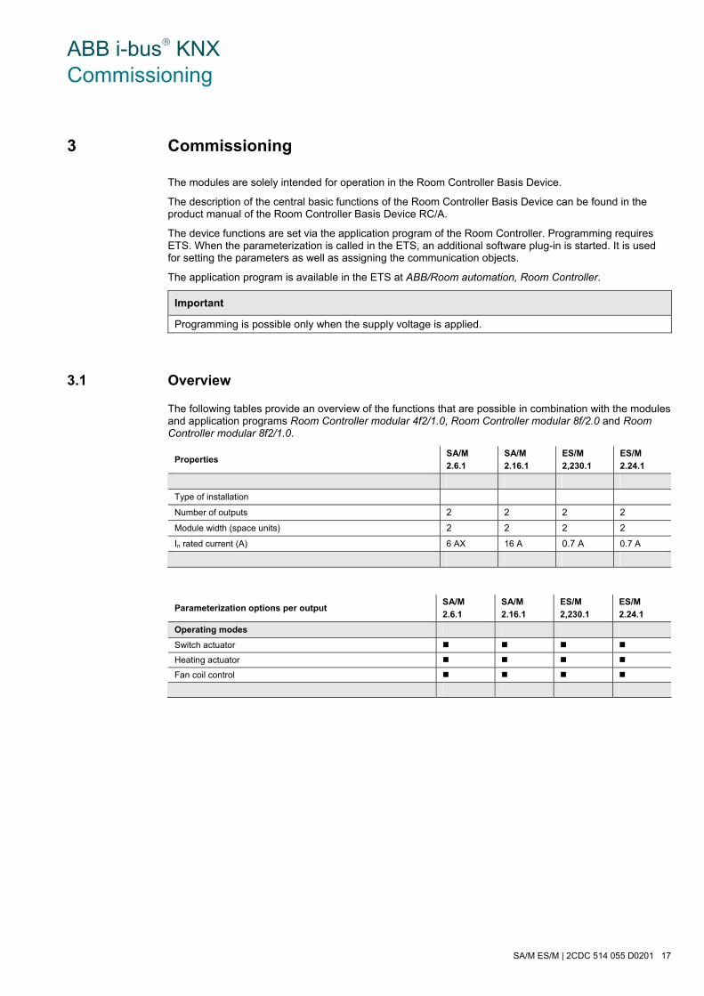
ABB i-bus® KNX Commissioning
SA/M ES/M | 2CDC 514 055 D0201 17
3 Commissioning
The modules are solely intended for operation in the Room Controller Basis Device.
The description of the central basic functions of the Room Controller Basis Device can be found in the product manual of the Room Controller Basis Device RC/A.
The device functions are set via the application program of the Room Controller. Programming requires ETS. When the parameterization is called in the ETS, an additional software plug-in is started. It is used for setting the parameters as well as assigning the communication objects.
The application program is available in the ETS at ABB/Room automation, Room Controller.
Important
Programming is possible only when the supply voltage is applied.
3.1 Overview
The following tables provide an overview of the functions that are possible in combination with the modules and application programs Room Controller modular 4f2/1.0, Room Controller modular 8f/2.0 and Room Controller modular 8f2/1.0.
Properties SA/M
2.6.1
SA/M
2.16.1
ES/M
2,230.1
ES/M
2.24.1
Type of installation
Number of outputs 2 2 2 2
Module width (space units) 2 2 2 2
In rated current (A) 6 AX 16 A 0.7 A 0.7 A
Parameterization options per output SA/M
2.6.1
SA/M
2.16.1
ES/M
2,230.1
ES/M
2.24.1
Operating modes
Switch actuator
Heating actuator
Fan coil control

ABB i-bus® KNX Commissioning
18 2CDC 514 055 D0201 | SA/M ES/M
Operating mode Switch actuator SA/M
2.6.1
SA/M
2.16.1
ES/M
2,230.1
ES/M
2.24.1
General
Status response of switching state
Reaction on bus voltage failure
Reaction on bus voltage recovery
Function Time
Staircase lighting
– Staircase lighting permanent ON
– Staircase lighting warning
– Duration of staircase lighting
Switching ON and OFF delay
Flashing
Preset
Preset 1/2
Preset 3/4
Contact setting can be set via bus
Function Scene
64 scenes
Recall and save via KNX with 8 bit telegram
Function Logic
Logical AND function
Logical OR function
Logical XOR function
Logical GATE function
Function Safety
Forced operation
Function Threshold
Threshold value 1
– upper limit
– lower limit
Threshold value 2
– upper limit
– lower limit
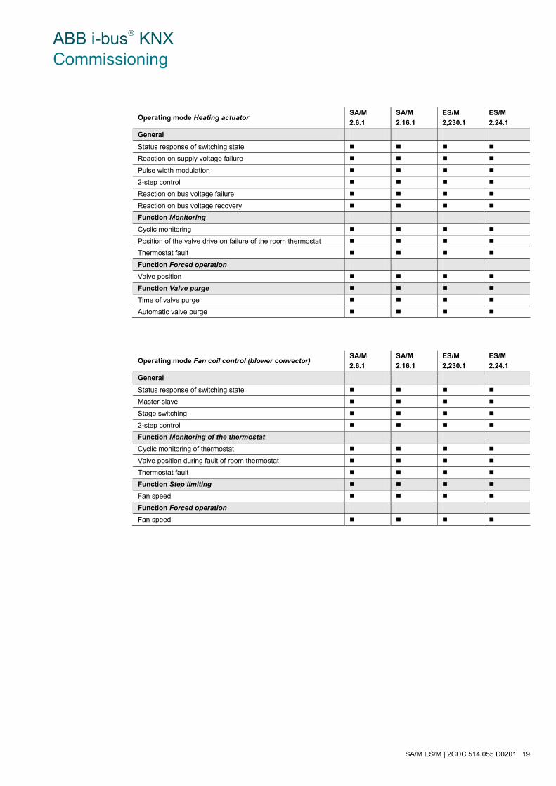
ABB i-bus® KNX Commissioning
SA/M ES/M | 2CDC 514 055 D0201 19
Operating mode Heating actuator SA/M
2.6.1
SA/M
2.16.1
ES/M
2,230.1
ES/M
2.24.1
General
Status response of switching state
Reaction on supply voltage failure
Pulse width modulation
2-step control
Reaction on bus voltage failure
Reaction on bus voltage recovery
Function Monitoring
Cyclic monitoring
Position of the valve drive on failure of the room thermostat
Thermostat fault
Function Forced operation
Valve position
Function Valve purge
Time of valve purge
Automatic valve purge
Operating mode Fan coil control (blower convector) SA/M
2.6.1
SA/M
2.16.1
ES/M
2,230.1
ES/M
2.24.1
General
Status response of switching state
Master-slave
Stage switching
2-step control
Function Monitoring of the thermostat
Cyclic monitoring of thermostat
Valve position during fault of room thermostat
Thermostat fault
Function Step limiting
Fan speed
Function Forced operation
Fan speed
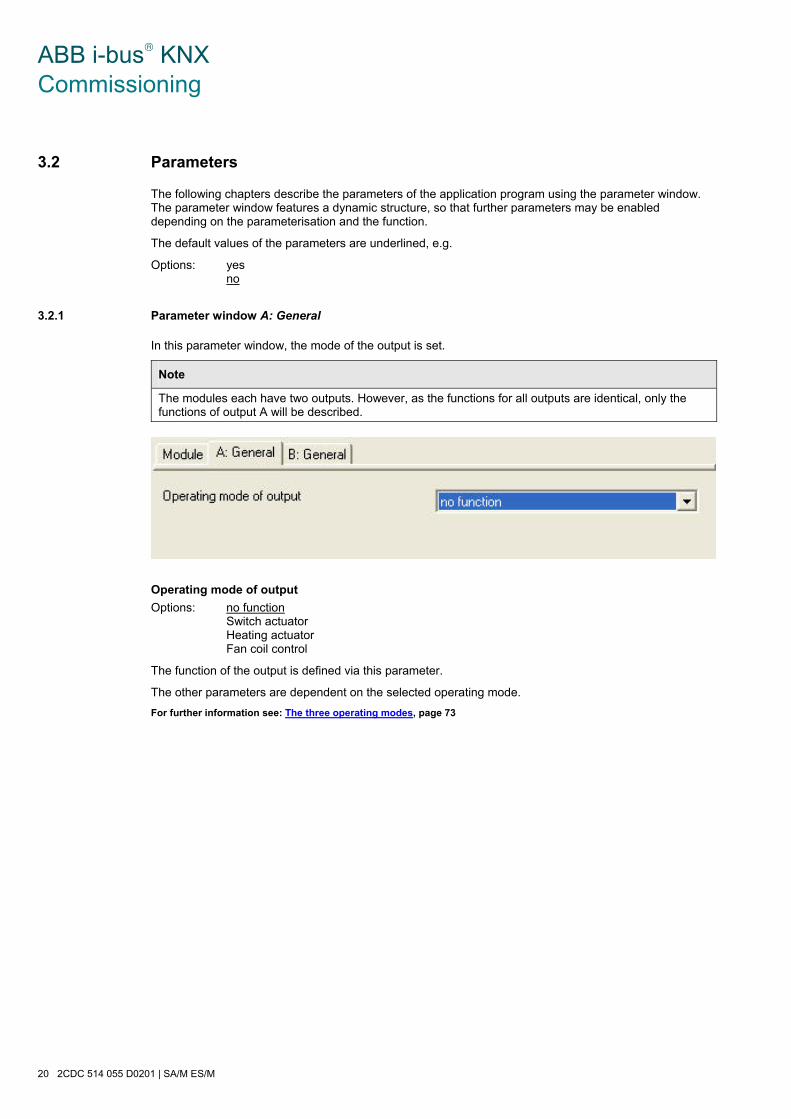
ABB i-bus® KNX Commissioning
20 2CDC 514 055 D0201 | SA/M ES/M
3.2 Parameters
The following chapters describe the parameters of the application program using the parameter window. The parameter window features a dynamic structure, so that further parameters may be enabled depending on the parameterisation and the function.
The default values of the parameters are underlined, e.g.
Options: yes no
3.2.1 Parameter window A: General
In this parameter window, the mode of the output is set.
Note
The modules each have two outputs. However, as the functions for all outputs are identical, only the functions of output A will be described.
Operating mode of output
Options: no function Switch actuator Heating actuator Fan coil control
The function of the output is defined via this parameter.
The other parameters are dependent on the selected operating mode.
For further information see: The three operating modes, page 73

ABB i-bus® KNX Commissioning
SA/M ES/M | 2CDC 514 055 D0201 21
3.3 Operating mode Switch Actuator
3.3.1 Parameter window A: General
General settings are carried out in this parameter window, e.g. the reaction during/after bus voltage failure and the status response function.
Status response of switching state
Options: no yes (object “Status switch”)
The communication object Status switch is enabled with this parameter. It is used to indicate the current switching state on the bus.
• yes: The following parameters appear:
inverted
Options: no (0 = opened, 1 = closed) yes (0 = closed, 1=opened)
• yes: the status response communication object sends a 1 when the relay contact is opened and a 0 when the relay contact is closed. This can be useful, for example, when the output is operated as a normally closed contact, so that the telegram value 1 is received as a status response with an ON telegram.

ABB i-bus® KNX Commissioning
22 2CDC 514 055 D0201 | SA/M ES/M
sending after bus voltage recovery
Options: no yes
This parameter determines whether the switching state is updated on the bus after bus voltage recovery. The update is carried out in connection with the transmission delay of the Room Controller.
Reaction on bus voltage failure
Options: contact open contact closed unchanged
The output can adopt a defined state on bus voltage failure via this parameter.
• contact open: The output contact is opened with a bus voltage failure.
• contact closed: The contact is closed with a bus voltage failure.
• unchanged: The contact position remains unchanged at bus voltage failure. The output can still be operated, e.g. via push buttons that are connected to binary inputs of the same device.
Reaction on bus voltage recovery
Options: ON (1) OFF (0) unchanged
• ON (1): The output is switched on at bus voltage recovery.
• OFF (0): The output is switched off at bus voltage recovery.
• unchanged: The contact position remains unchanged at bus voltage recovery.
On bus voltage recovery, the output is set once the parameterized initialisation time of the Room Controller has elapsed.
Note
This setting can be overwritten by the parameters of the parameter window A: Function.

ABB i-bus® KNX Commissioning
SA/M ES/M | 2CDC 514 055 D0201 23
3.3.2 Parameter window A: Function
In this parameter window, basic settings for the function of an output are carried out. Additional functions can also be enabled.
Reaction of output
Options: normally closed contact normally opened contact
This parameter determines whether the output operates as a normally closed contact or normally opened contact.
• Normally opened contact: An ON telegram closes the contact and an OFF telegram opens the contact.
• Normally closed contact: An ON telegram opens the contact and an OFF telegram closes the contact.
Enable function “time, staircase lighting, flashing“
Options: no yes
• yes: The parameter window Parameter window A: Time, page 25, is enabled.
Enable function “presets“
Options: no yes
• yes: The parameter window Parameter window A: Preset, page 32, is enabled.
ABB i-bus® KNX Commissioning
24 2CDC 514 055 D0201 | SA/M ES/M
Enable function “scene (8 bit)“
Options: no yes
• yes: The parameter window Parameter window A: Scene, page 34, is enabled.
Enable function “logic“
Options: no yes
• yes: The parameter window Parameter window A: Logic, page 36, is enabled.
Enable function “forced operation“ and “cyclic monitoring”
Options: no yes
• yes: The parameter window Parameter window A: Safety, page 38, is enabled.
Enable threshold function
Options: no yes
• yes: The parameter window Parameter window A: Threshold, page 41, is enabled.

ABB i-bus® KNX Commissioning
SA/M ES/M | 2CDC 514 055 D0201 25
3.3.3 Parameter window A: Time
In this parameter window, all settings for the function time are undertaken: Switching ON and OFF delay, Staircase lighting and Flashing. This communication object is visible if in Parameter window A: Function, page 23, the parameter Enable function "time, staircase lighting, flashing" has been selected with the option yes.
Explanations concerning the time functions can be found at Time functions, page 74. Please observe the Function chart, on page 83.
Time function
Options: staircase lighting function ON and OFF delay flashing
This parameter defines the type of the time function for an output.
• staircase lighting function: The value, with which the staircase lighting is switched on and off, can be parameterized. The staircase lighting time is started when the function is activated. It is switched off immediately after the staircase lighting time has been completed.
Note
The staircase lighting function can be started by sending a telegram to the communication object It can be paramterized in the parameter window A: Function by the parameter
ABB i-bus® KNX Commissioning
26 2CDC 514 055 D0201 | SA/M ES/M
• ON and OFF delay: The output can be switched on or off with a delay via this function.
• flashing: The output starts to flash as soon as the parameterized value is received on the communication object Switch. The flashing period can be adjusted via the parameterized time duration for ON or OFF. The output is switched on at the start of the flashing period. When a new value is received on the communication object Switch, the flashing period will recommence. The relay state after flashing can be programmed. The communication object Status switch indicates the current relay state during flashing.
Note
The staircase lighting function can be started by sending a telegram to the communication object It can be paramterized in the parameter window A: Function by the parameter
The following parameter appears with the selection Staircase lighting function:
Duration of staircase lighting
Options: [h:min:s]
The staircase lighting time defines how long the contact is closed and how long the light remains on after an ON telegram. The staircase lighting time may extend depending on the value set in the parameter Warning before end of staircase lighting.
Extending staircase lighting by multiple operation (“pumping up”)
Options: no up to max. 1x staircase lighting time up to max. 2x staircase lighting time up to max. 3x staircase lighting time up to max. 4x staircase lighting time up to max. 5x staircase lighting time
If a further ON telegram is received during the staircase lighting time sequence, the remaining staircase lighting time can be extended by a further period. This is possible by repeated operation of the push button (“pumping up“), until the maximum programmed number of retriggering operations is reached. The maximum time can be set to 1, 2, 3, 4 or 5-fold time of the staircase lighting time.
The staircase lighting time is extended by “pumping up” to the maximum time. If some of the time has already timed out, the staircase lighting time can again be extended to the maximum time by “pumping up”. The parameterized maximum time may not however be exceeded.
• no: The receipt of a further ON telegram is ignored. The staircase lighting time continues without modification to completion.
• yes (retriggerable): The staircase lighting time is reset each time by a renewed ON telegram and starts to count again each time. This process can be repeated as often as desired using this selection.
• up to max. 2/3/4/5 x staircase lighting time: The staircase lighting time is extended by the 2/3/4/5-fold staircase lighting time with a renewed ON telegram.

ABB i-bus® KNX Commissioning
SA/M ES/M | 2CDC 514 055 D0201 27
Staircase lighting can be switched off
Options: no yes
• yes: The staircase lighting is switched off prematurely by an OFF telegram.
Note
If yes is selected, the staircase lighting can also be switched off via the other communication objects, if they cause switch off: Logical connection, Preset, Light scene, Disable, Permanent ON, Forced operation.
Restart of staircase time after end of permanent ON
Options: no yes
The function of continuously ON is controlled via the Permanent ON communication object value. If the communication object receives a telegram with the value 1, the output is switched ON irrespective of the value of the communication object Switch and remains switched on until the communication object Permanent ON has the value 0.
Note
Permanent ON only switches ON and “masks” the other functions. This means that the other functions, e.g. staircase time or ”pumping up” continue to run in the background but do not initiate a reaction. After the end of permanent ON, the switching state, which would result without the permanent ON function, becomes active.
• no: The lighting switches off if permanent ON is ended.
• yes: The lighting remains on, and the staircase lighting time restarts.
Warning before end of staircase lighting
Options: no yes
Before the staircase lighting time times-out, the user can be informed of the imminent switch off of the lighting by a warning. If the warning time is not equal to 0, the staircase lighting time is extended by the warning time. The warning time is not modified by the “pumping up” action.
• no: No warning is given, the staircase light switches off immediately after the staircase lighting time elapses. If the staircase lighting is ended prematurely, e.g. by a switching telegram, no warning is given.
• yes: The following parameters appear:
Warning time
Options: [h:min:s]
This parameter is visible if a warning is programmed before the staircase lighting time ends. The warning time must be entered in seconds. The staircase lighting time is extended by the warning time. The warning is triggered at the start of the warning time.
The warning time is not modified by “pumping up”.

ABB i-bus® KNX Commissioning
28 2CDC 514 055 D0201 | SA/M ES/M
Warning via
Options: object quick switching OFF/ON object and switching ON/OFF
• object: The communication object Warning staircase lighting is set to the value 1 at the commencement of warning time and remains set until the warning time has elapsed. The communication object can be used, for example, to switch a warning light.
• quick switching OFF/ON: Switching the output (briefly OFF and ON again).
• object and switching ON/OFF: Both options are used together.
Duration of staircase lighting can be changed by object
Options: no yes
This parameter determines if a change of the staircase lighting time is possible via the bus.
• no: No modification of the staircase lighting time is possible via the bus.
• yes: A 2 byte Duration of staircase lighting communication object is enabled. The staircase lighting time can be changed via the bus here. The value defines the staircase lighting time in seconds. The function Staircase lightning, which has already commenced, is completed. A change of the staircase lighting time is used the next time it is accessed.
How does the staircase light behave with bus voltage failure?
The behaviour at bus voltage failure is determined by the parameter Reaction on bus voltage failure in the Parameter window A: General, page 21.
After supply voltage recovery the staircase light is
Options: switched OFF switched ON
This parameter determines the response of the staircase lighting after bus voltage or supply voltage recovery.
• switched ON: The staircase lighting time restarts with bus voltage recovery.
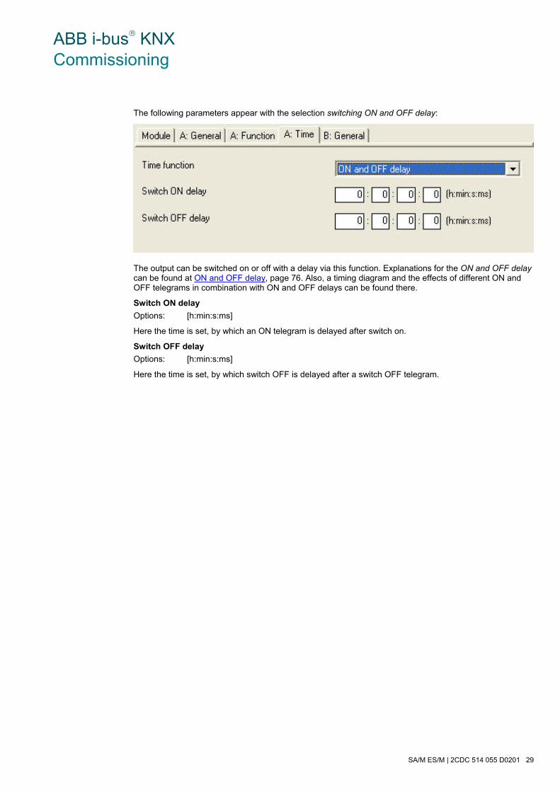
ABB i-bus® KNX Commissioning
SA/M ES/M | 2CDC 514 055 D0201 29
The following parameters appear with the selection switching ON and OFF delay:
The output can be switched on or off with a delay via this function. Explanations for the ON and OFF delay can be found at ON and OFF delay, page 76. Also, a timing diagram and the effects of different ON and OFF telegrams in combination with ON and OFF delays can be found there.
Switch ON delay
Options: [h:min:s:ms]
Here the time is set, by which an ON telegram is delayed after switch on.
Switch OFF delay
Options: [h:min:s:ms]
Here the time is set, by which switch OFF is delayed after a switch OFF telegram.
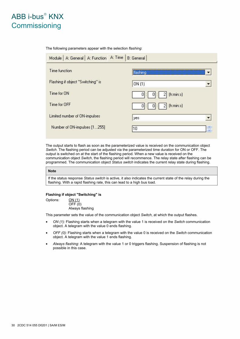
ABB i-bus® KNX Commissioning
30 2CDC 514 055 D0201 | SA/M ES/M
The following parameters appear with the selection flashing:
The output starts to flash as soon as the parameterized value is received on the communication object Switch. The flashing period can be adjusted via the parameterized time duration for ON or OFF. The output is switched on at the start of the flashing period. When a new value is received on the communication object Switch, the flashing period will recommence. The relay state after flashing can be programmed. The communication object Status switch indicates the current relay state during flashing.
Note
If the status response Status switch is active, it also indicates the current state of the relay during the flashing. With a rapid flashing rate, this can lead to a high bus load.
Flashing if object "Switching" is
Options: ON (1) OFF (0) Always flashing
This parameter sets the value of the communication object Switch, at which the output flashes.
• ON (1): Flashing starts when a telegram with the value 1 is received on the Switch communication object. A telegram with the value 0 ends flashing.
• OFF (0): Flashing starts when a telegram with the value 0 is received on the Switch communication object. A telegram with the value 1 ends flashing.
• Always flashing: A telegram with the value 1 or 0 triggers flashing. Suspension of flashing is not possible in this case.
ABB i-bus® KNX Commissioning
SA/M ES/M | 2CDC 514 055 D0201 31
Time for ON
Options: [h:min:s]
This time for ON defines how long the output is switched ON during a flashing period. The smallest value is 1 second.
Time for OFF
Options: [h:min:s]
This time for OFF defines how long the output is switched OFF during a flashing period. The smallest value is 1 second.
Limited number of ON-impulses
Options: no yes
The number of flashing pulses can be limited using this parameter. This is useful to avoid unnecessary wear of the contacts caused by flashing. After the output has been switched on and off for an adjustable incidence (number of ON impulses), it will be switched off permanently.
Number of ON-impulses [1…255]
Options: 1…10…255
This parameter defines the maximum number of pulses.
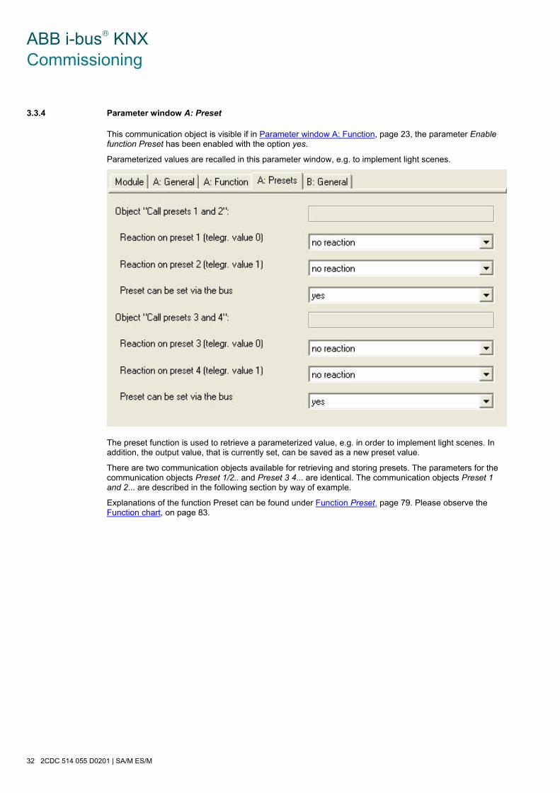
ABB i-bus® KNX Commissioning
32 2CDC 514 055 D0201 | SA/M ES/M
3.3.4 Parameter window A: Preset
This communication object is visible if in Parameter window A: Function, page 23, the parameter Enable function Preset has been enabled with the option yes.
Parameterized values are recalled in this parameter window, e.g. to implement light scenes.
The preset function is used to retrieve a parameterized value, e.g. in order to implement light scenes. In addition, the output value, that is currently set, can be saved as a new preset value.
There are two communication objects available for retrieving and storing presets. The parameters for the communication objects Preset 1/2.. and Preset 3 4... are identical. The communication objects Preset 1 and 2... are described in the following section by way of example.
Explanations of the function Preset can be found under Function Preset, page 79. Please observe the Function chart, on page 83.

ABB i-bus® KNX Commissioning
SA/M ES/M | 2CDC 514 055 D0201 33
Object “Call presets 1 and 2”:
Reaction on preset 1 (telegr. value 0)
Options: no reaction ON (1) OFF (0) restore old value reset to parameterized value before preset 2
Preset 1 is retrieved if the communication object Call preset 1/2 receives the telegram value 0. The output can control a defined state in this case.
• no reaction: The output does not respond.
• ON (1): The output is switched on.
• OFF (2): The output is switched off.
• restore old value: Recreates the state before the last retrieval of Preset 2.
Note
With Preset 2, the lighting in a conference room is retrieved for a presentation. When the presentation is finished, the lighting is restored via Preset1 to the state it was in beforehand.
• reset to parameterized value before preset 2: Resets Preset 2 to the parameterized value. This can be advisable if the preset can be stored via the bus.
Note
With the parameterisation restore old value before preset 2 or restore parameterized value of preset 2, saving of the preset concerned has no effect. The saved value is not recalled, but rather the parameterized function is undertaken.
Reaction on preset 2 (telegr. value 1)
Options: no reaction ON (1) OFF (0)
This parameter determines the contact position that the output assumes when Preset 2 is recalled, i.e., communication object Recall Preset … receives a telegram with the value 1.
Preset can be set via the bus
Options: no yes
This parameter enables the communication object Save preset 1/2. It is thus possible to save the current contact position as a new preset value. It is used to store the current contact position as a preset value.
Telegram value 0 saves preset 1, whereas telegram value 1 saves preset 2.
If in parameter Reaction on preset 1 (telegr. value 0) the option no reaction, restore old value before preset 2 or restore parameterized value of preset 2 has been selected, no new communication object value is saved.
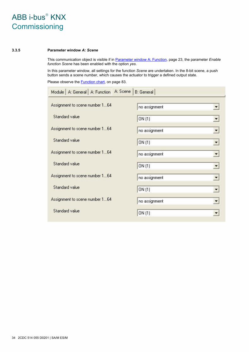
ABB i-bus® KNX Commissioning
34 2CDC 514 055 D0201 | SA/M ES/M
3.3.5 Parameter window A: Scene
This communication object is visible if in Parameter window A: Function, page 23, the parameter Enable function Scene has been enabled with the option yes.
In this parameter window, all settings for the function Scene are undertaken. In the 8-bit scene, a push button sends a scene number, which causes the actuator to trigger a defined output state.
Please observe the Function chart, on page 83.

ABB i-bus® KNX Commissioning
SA/M ES/M | 2CDC 514 055 D0201 35
Assignment to scene number 1…64
Options: no assignment Scene 1 … Scene 64
With the function Scene up to a max. of 64 different scenes (1...64) can be addressed via a group address. With this group address all slaves, who are integrated into a scene, are linked via a 1 byte communication object. The following information is contained in a telegram:
• Number of the scene (1…64)
• Telegram: Call scene or Save scene.
The output can be allocated to up to 5 scenes.
Standard value
Options: ON (1) OFF (0)
Using this parameter, you can set which state the output adopts when the scene is retrieved.
By storing a scene, the user has the opportunity to modify the programmed value. After programming or after a supply voltage failure, the value that is parameterized here is restored.
Note
When a scene is retrieved - the Time functions are restarted, - the logical connections are re-evaluated.

ABB i-bus® KNX Commissioning
36 2CDC 514 055 D0201 | SA/M ES/M
3.3.6 Parameter window A: Logic
This communication object is visible if in Parameter window A: Function, page 23, the parameter Enable function logic has been enabled with the option yes.
In this parameter window, all settings for the function Connection/Logic are undertaken.
The function Connection/Logic provides up to two logic objects for each output, which can be logically linked with the Switch communication object.
The logic is always re-calculated when a communication object value is received. Hereby, the communication object Logical connection 1 is first of all evaluated with the communication object Switch. The result is then liked with communication object Logical connection 2.
The parameters are identical for both logic objects. The function is described in the following section using the example of communication object Logical connection 1.
Explanation for the logical function can be found at Function Logic, page 78. Please observe the Function chart, on page 83.
ABB i-bus® KNX Commissioning
SA/M ES/M | 2CDC 514 055 D0201 37
Function of object "Logical connection 1"
Function of object "Logical connection 2"
Options: inactive AND OR XOR gate function
The logic function of the communication object Logical connection is defined here. All three standard operators (AND, OR, XOR) are possible. The gate function is also available, which can block switching telegrams.
Result is inverted
Options: no yes
• no: There is no inversion.
• yes: The result of the logical connection is inverted.
Object value after bus voltage recovery
Options: ON (1) OFF (0)
This parameter defines the value allocated to the communication object Logical connection 1 or Logical connection 2 at bus voltage recovery.
A further parameter appears if gate function is selected with the parameter Function of object "Logical connection 1":
Gate disabled, if “Logical connection …“ is
Options: ON (1) OFF (0)
This parameter defines the value, at which the communication object disables the GATE.
Disabling of the gate means that the telegrams received on the Switch communication object are ignored. As long as the GATE is activated, the value which was sent last to the input of the GATE remains on the output. After a GATE is blocked, the value that was on the output before the block remains on the output of the GATE.
After the GATE is enabled, this value will be retained until a new value is received.
For further information see: 2Function chart, page 83
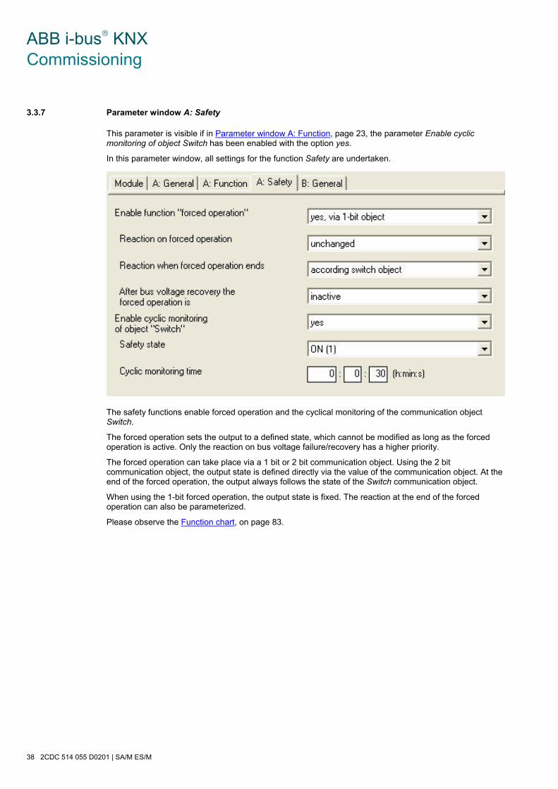
ABB i-bus® KNX Commissioning
38 2CDC 514 055 D0201 | SA/M ES/M
3.3.7 Parameter window A: Safety
This parameter is visible if in Parameter window A: Function, page 23, the parameter Enable cyclic monitoring of object Switch has been enabled with the option yes.
In this parameter window, all settings for the function Safety are undertaken.
The safety functions enable forced operation and the cyclical monitoring of the communication object Switch.
The forced operation sets the output to a defined state, which cannot be modified as long as the forced operation is active. Only the reaction on bus voltage failure/recovery has a higher priority.
The forced operation can take place via a 1 bit or 2 bit communication object. Using the 2 bit communication object, the output state is defined directly via the value of the communication object. At the end of the forced operation, the output always follows the state of the Switch communication object.
When using the 1-bit forced operation, the output state is fixed. The reaction at the end of the forced operation can also be parameterized.
Please observe the Function chart, on page 83.

ABB i-bus® KNX Commissioning
SA/M ES/M | 2CDC 514 055 D0201 39
Enable function "forced operation"
Options: no yes, via 1-bit object yes, via 2-bit object
The forced operation function can be enabled via this parameter.
• no: The function is not enabled.
• yes, via 1-bit object: The following parameters appear:
Reaction on forced operation
Options: ON (1) OFF (0) unchanged
This parameter sets which state the output adopts during forced operation.
Reaction when forced operation ends
Options: ON (1) OFF (0) unchanged according switch object
The state of the relay at the end of the forced operation is defined using this parameter.
• ON (1): The output opens.
• OFF (0): The output closes.
• unchanged: The output remains unchanged.
• according switch object: The output follows the communication object Switch. The output can open, close, follow the communication object Switch or remain unchanged.
After bus voltage recovery the forced operation is
Options: active – OFF active – ON inactive
Using this parameter, the state of forced operation after bus voltage recovery is set.
• active – OFF: Forced operation is active and the output is closed.
• active – ON: Forced operation is active and the output is opened.
• inactive: Forced operation is inactive. The output follows the setting in the parameter window General.

ABB i-bus® KNX Commissioning
40 2CDC 514 055 D0201 | SA/M ES/M
• yes, via 2-bit object: The following parameters appear:
After bus voltage recovery the forced operation is
Options: active – OFF active – ON inactive
Using this parameter, the state of forced operation after bus voltage recovery is set.
• active – OFF: Forced operation is active and the output is closed.
• active – ON: Forced operation is active and the output is opened.
• inactive: Forced operation is inactive. The output follows the setting in the parameter window General.
Enable cyclic monitoring of object “Switch”
Options: no yes
This parameter enables cyclic monitoring of the communication object Switch. If the device does not receive any telegrams via the communication object Switch for an adjustable period, the output is set to the safety position. The telegram value can be 0 or 1.
This function is useful if the sensor sends the communication object Switch cyclically on the bus. It is recommended that the monitoring period is set slightly higher than three times the transmission cycle time.
• yes: The following parameters appear:
Safety state
Options: ON (1) OFF (0)
This parameter sets the state, which the relay adopts while the safety position is active. The safety position is automatically cancelled as soon as the device again receives a telegram on the communication object Switch.
Cyclic monitoring time
Options: [h:min:s]
This parameter sets the monitoring time with which the communication object Switch is observed.
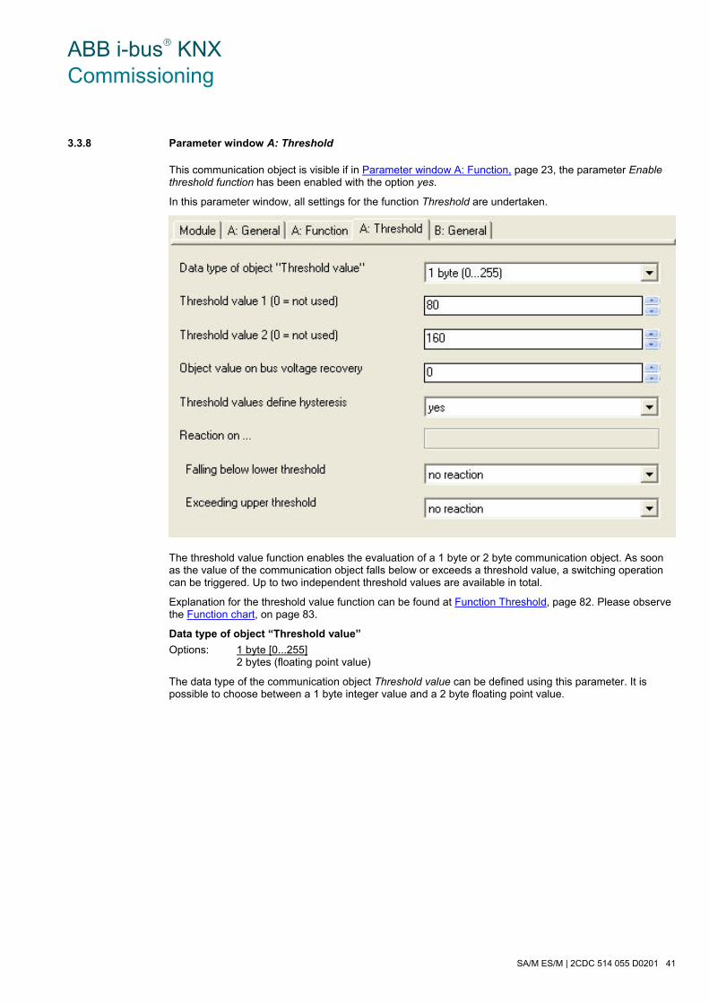
ABB i-bus® KNX Commissioning
SA/M ES/M | 2CDC 514 055 D0201 41
3.3.8 Parameter window A: Threshold
This communication object is visible if in Parameter window A: Function, page 23, the parameter Enable threshold function has been enabled with the option yes.
In this parameter window, all settings for the function Threshold are undertaken.
The threshold value function enables the evaluation of a 1 byte or 2 byte communication object. As soon as the value of the communication object falls below or exceeds a threshold value, a switching operation can be triggered. Up to two independent threshold values are available in total.
Explanation for the threshold value function can be found at Function Threshold, page 82. Please observe the Function chart, on page 83.
Data type of object “Threshold value”
Options: 1 byte [0...255] 2 bytes (floating point value)
The data type of the communication object Threshold value can be defined using this parameter. It is possible to choose between a 1 byte integer value and a 2 byte floating point value.

ABB i-bus® KNX Commissioning
42 2CDC 514 055 D0201 | SA/M ES/M
Threshold value 1 (0 = not used)
Threshold value 2 (0 = not used)
Options: 0…80…160…255 0...20,000...40,000...65,535
This parameter defines two threshold values. If the threshold values are not required, a 0 should be entered. The value range is dependent on the data type.
Object value on bus voltage recovery
Options: 0…255
This parameter determines the value of the communication object Threshold after bus voltage recovery.
Note
When a threshold value is exceeded - the time functions are restarted. - the logical connections are re-evaluated.
Threshold values define hysteresis
Options: no yes
This parameter defines whether the 1st and 2nd threshold values should be interpreted as hysteresis limits. The hysteresis can reduce unwanted violations of the threshold value if the input value fluctuates around one of the threshold values.
• no: The following parameters appear:
Reaction on…
Object value < lower threshold
Lower thrsh. <= object < upper thrsh.
Object value > = upper threshold
Options: no reaction OFF (0) ON (1)
These parameters are visible if the threshold values are not hysteresis limits. They define the reaction dependent on the threshold value.
• yes: The following parameters appear:
Reaction on…
Falling below lower threshold
Exceeding upper threshold
Options: no reaction OFF (0) ON (1)
These parameters are visible if the threshold values are interpreted as hysteresis limits. They define the reaction of the output if the communication object value Input threshold value exceeds or falls below the upper or lower threshold. A reaction only occurs if the object value was previously smaller or larger than the lower or upper threshold value.
For further information see: Function Threshold, page 82.

ABB i-bus® KNX Commissioning
SA/M ES/M | 2CDC 514 055 D0201 43
3.3.9 Brief overview of the communication objects
Flags CO No.
Function Name Data Point Type (DPT)
Length C R W T A
0 Switch Output A DPT 1.001 1 bit x x
1 Status Switch Output A DPT 1.001 1 bit x x x
2 Permanent ON Output A DPT 1.001 1 bit x x
3 Warning staircase lighting Output A DPT 1.005 1 bit x x
4 Duration of staircase lighting Output A DPT 7.005 1 bit x x x
5 Recall Preset 1/2 Output A DPT 1.017 1 bit x x
6 Set Preset 1/2 Output A DPT 1.017 1 bit x x
7 Recall Preset 3/4 Output A DPT 1.017 1 bit x x
8 Set Preset 3/4 Output A DPT 1.017 1 bit x x
9 8 bit scene Output A DPT 18.001 1 byte x x
10 Connection 1 Output A DPT 1.002 1 byte x x
11 Connection 2 Output A DPT 1.002 1 bit x x
Priority / forced operation Output A DPT 1.003 1 bit x x 12
Priority / forced operation Output A DPT 2.001 2 bit x x
Threshold Output A DPT 5.010 1 byte x x 13
Threshold Output A DPT 7.001 2 byte x x
14 Not assigned
15…
28
Output B,
the same CO as output A B: see output A
29 Status byte Output A…B 1 byte x x X
*CO = communication object

ABB i-bus® KNX Commissioning
44 2CDC 514 055 D0201 | SA/M ES/M
3.3.10 Communication objects General
No. Function Name Data type Flags
0 Switch Output A 1 bit
DPT 1.001
C, W
This communication object is used for switching of the output ON/OFF. The device receives a switch telegram via the switch object.
Normally open contact:
Telegram value 1 = switch ON 0 = switch OFF
Normally closed contact:
Telegram value 1 = switch OFF 0 = switch ON
Note
With logical connections or forced operations, a modification of the Switch communication object does not necessarily lead to a change of the contact position.
For further information see: Function chart, page 83
1 Status Switch Output A 1 bit
DPT 1.001
C, R, T
This communication object is enabled if in parameter window A: General in parameter Status response of switching state the option yes (Object “Status switch”) has been selected. It indicates the current state of the output and is sent when a value changes. The status value can be inverted.
Telegram value: Default: 0 = relay opened
1 = relay is closed
Inverted: 0 = relay is closed 1 = relay is closed
Note
This communication object may have an incorrect value after mains voltage failure if the behaviour for both bus voltage failure as well as bus voltage recovery is set to unchanged.
29 Status byte Output A…B 1 byte non DPT C, R, T
This communication object provides further information about the operating state of the device (only Electronic Switch Actuator Modules ES/M 2.230.1 and ES/M 2.24.1).
Bit = Meaning
0 = Overload (e.g. short circuit) on output A
1 = Overload (e.g. short circuit) on output B
2 = not used, always “0”
3 = not used, always “0”
4 = not used, always “0”
5 = not used, always “0”
6 = Incoming supply voltage available
7 = Supply voltage type: 0 = AC; 1 = DC
A detailed table for encoding the communication object value can be found at Table of values of communication object Status byte, page 93.
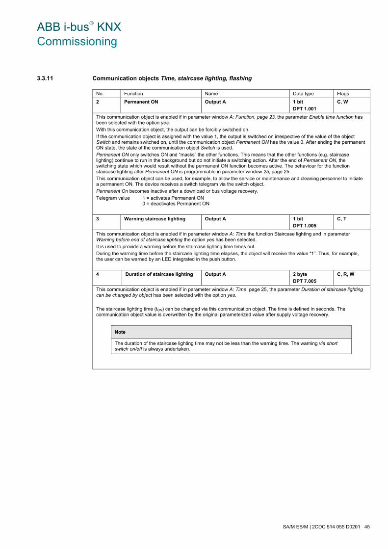
ABB i-bus® KNX Commissioning
SA/M ES/M | 2CDC 514 055 D0201 45
3.3.11 Communication objects Time, staircase lighting, flashing
No. Function Name Data type Flags
2 Permanent ON Output A 1 bit
DPT 1.001
C, W
This communication object is enabled if in parameter window A: Function, page 23, the parameter Enable time function has been selected with the option yes.
With this communication object, the output can be forcibly switched on.
If the communication object is assigned with the value 1, the output is switched on irrespective of the value of the object Switch and remains switched on, until the communication object Permanent ON has the value 0. After ending the permanent ON state, the state of the communication object Switch is used.
Permanent ON only switches ON and “masks” the other functions. This means that the other functions (e.g. staircase lighting) continue to run in the background but do not initiate a switching action. After the end of Permanent ON, the switching state which would result without the permanent ON function becomes active. The behaviour for the function staircase lighting after Permanent ON is programmable in parameter window 25, page 25.
This communication object can be used, for example, to allow the service or maintenance and cleaning personnel to initiate a permanent ON. The device receives a switch telegram via the switch object.
Permanent On becomes inactive after a download or bus voltage recovery.
Telegram value 1 = activates Permanent ON 0 = deactivates Permanent ON
3 Warning staircase lighting Output A 1 bit
DPT 1.005
C, T
This communication object is enabled if in parameter window A: Time the function Staircase lighting and in parameter Warning before end of staircase lighting the option yes has been selected.
It is used to provide a warning before the staircase lighting time times out.
During the warning time before the staircase lighting time elapses, the object will receive the value “1”. Thus, for example, the user can be warned by an LED integrated in the push button.
4 Duration of staircase lighting Output A 2 byte
DPT 7.005
C, R, W
This communication object is enabled if in parameter window A: Time, page 25, the parameter Duration of staircase lighting can be changed by object has been selected with the option yes.
The staircase lighting time (tON) can be changed via this communication object. The time is defined in seconds. The communication object value is overwritten by the original parameterized value after supply voltage recovery.
Note
The duration of the staircase lighting time may not be less than the warning time. The warning via short switch on/off is always undertaken.
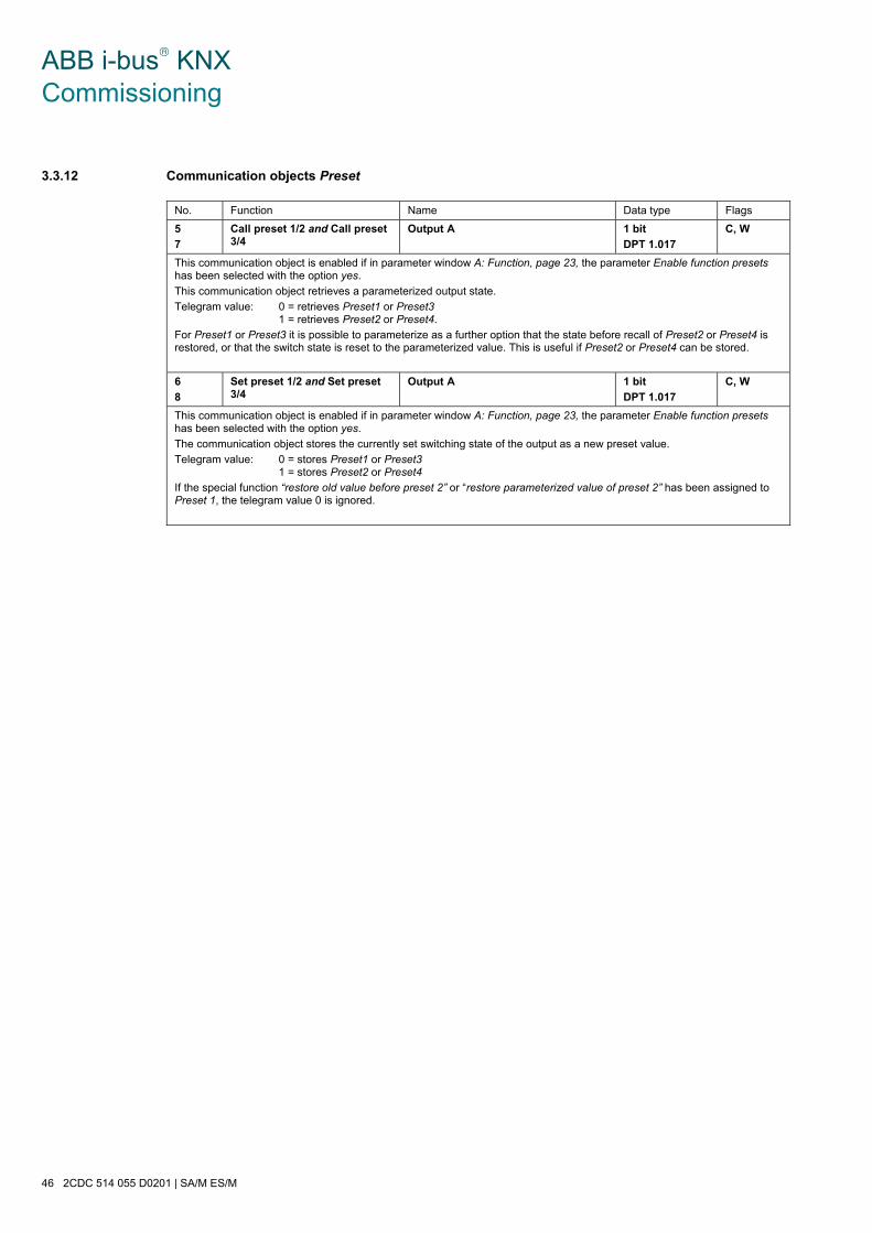
ABB i-bus® KNX Commissioning
46 2CDC 514 055 D0201 | SA/M ES/M
3.3.12 Communication objects Preset
No. Function Name Data type Flags
5
7
Call preset 1/2 and Call preset 3/4
Output A 1 bit
DPT 1.017
C, W
This communication object is enabled if in parameter window A: Function, page 23, the parameter Enable function presets has been selected with the option yes.
This communication object retrieves a parameterized output state.
Telegram value: 0 = retrieves Preset1 or Preset3 1 = retrieves Preset2 or Preset4.
For Preset1 or Preset3 it is possible to parameterize as a further option that the state before recall of Preset2 or Preset4 is restored, or that the switch state is reset to the parameterized value. This is useful if Preset2 or Preset4 can be stored.
6
8
Set preset 1/2 and Set preset 3/4
Output A 1 bit
DPT 1.017
C, W
This communication object is enabled if in parameter window A: Function, page 23, the parameter Enable function presets has been selected with the option yes.
The communication object stores the currently set switching state of the output as a new preset value.
Telegram value: 0 = stores Preset1 or Preset3 1 = stores Preset2 or Preset4
If the special function “restore old value before preset 2” or “restore parameterized value of preset 2” has been assigned to Preset 1, the telegram value 0 is ignored.
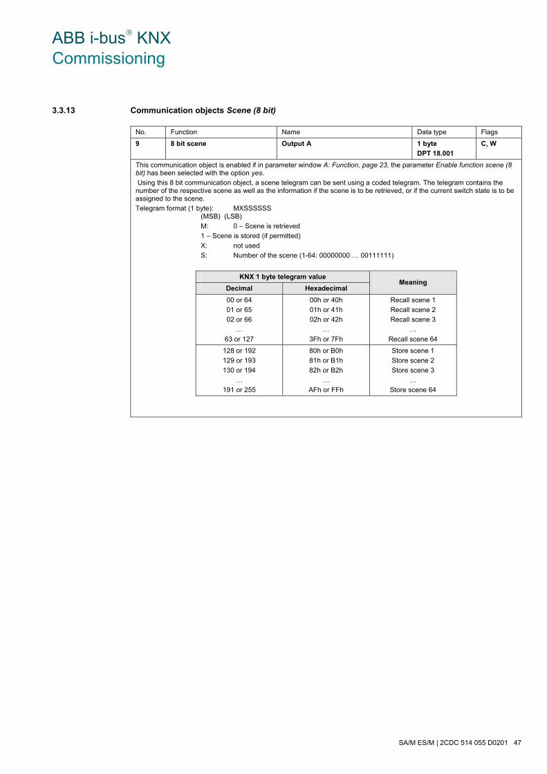
ABB i-bus® KNX Commissioning
SA/M ES/M | 2CDC 514 055 D0201 47
3.3.13 Communication objects Scene (8 bit)
No. Function Name Data type Flags
9 8 bit scene Output A 1 byte
DPT 18.001
C, W
This communication object is enabled if in parameter window A: Function, page 23, the parameter Enable function scene (8 bit) has been selected with the option yes.
Using this 8 bit communication object, a scene telegram can be sent using a coded telegram. The telegram contains the number of the respective scene as well as the information if the scene is to be retrieved, or if the current switch state is to be assigned to the scene.
Telegram format (1 byte): MXSSSSSS (MSB) (LSB)
M: 0 – Scene is retrieved
1 – Scene is stored (if permitted)
X: not used
S: Number of the scene (1-64: 00000000 … 00111111)
KNX 1 byte telegram value
Decimal Hexadecimal Meaning
00 or 64
01 or 65
02 or 66
…
63 or 127
00h or 40h
01h or 41h
02h or 42h
…
3Fh or 7Fh
Recall scene 1
Recall scene 2
Recall scene 3
…
Recall scene 64
128 or 192
129 or 193
130 or 194
…
191 or 255
80h or B0h
81h or B1h
82h or B2h
…
AFh or FFh
Store scene 1
Store scene 2
Store scene 3
…
Store scene 64

ABB i-bus® KNX Commissioning
48 2CDC 514 055 D0201 | SA/M ES/M
3.3.14 Communication objects Connection/Logic
No. Function Name Data type Flags
10 Connection 1 Output A 1 bit
DPT 1.002
C, W
This communication object is enabled if in parameter window A: Function, page 23, the parameter Enable function logic has been selected with the option yes.
Using this communication object, the output of the first of two logic objects can be assigned. The logical connection is defined in the parameter window A: Logic.
First of all, the communication object Switch is linked to Logical connection 1. The result is then liked with object Logical connection 2. The type of logical connection involved is defined in the parameters.
Note
The values of the communication objects Logical connection 1/2 are stored at bus voltage failure. The values are restored at bus voltage recovery.
If values of the communication objects Logical connection 1/2 were not assigned, they will be deactivated.
At a reset via the bus, the values of the communication objects Logical connection 1/2 remain unchanged.
For further information see: 2Function Logic, page 78
11 Connection 2 Output A 1 bit
DPT 1.002
C, W
See communication object 10
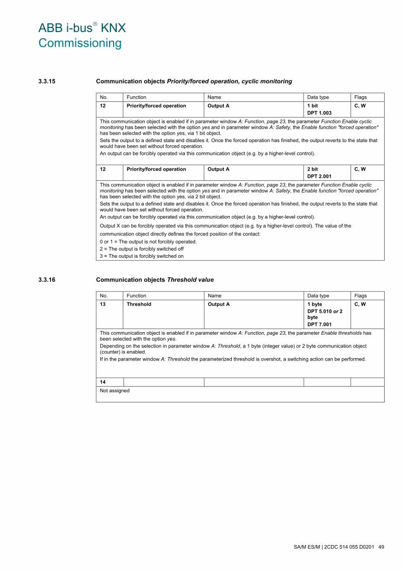
ABB i-bus® KNX Commissioning
SA/M ES/M | 2CDC 514 055 D0201 49
3.3.15 Communication objects Priority/forced operation, cyclic monitoring
No. Function Name Data type Flags
12 Priority/forced operation Output A 1 bit
DPT 1.003
C, W
This communication object is enabled if in parameter window A: Function, page 23, the parameter Function Enable cyclic monitoring has been selected with the option yes and in parameter window A: Safety, the Enable function "forced operation" has been selected with the option yes, via 1 bit object.
Sets the output to a defined state and disables it. Once the forced operation has finished, the output reverts to the state that would have been set without forced operation.
An output can be forcibly operated via this communication object (e.g. by a higher-level control).
12 Priority/forced operation Output A 2 bit
DPT 2.001
C, W
This communication object is enabled if in parameter window A: Function, page 23, the parameter Function Enable cyclic monitoring has been selected with the option yes and in parameter window A: Safety, the Enable function "forced operation" has been selected with the option yes, via 2 bit object.
Sets the output to a defined state and disables it. Once the forced operation has finished, the output reverts to the state that would have been set without forced operation.
An output can be forcibly operated via this communication object (e.g. by a higher-level control).
Output X can be forcibly operated via this communication object (e.g. by a higher-level control). The value of the
communication object directly defines the forced position of the contact:
0 or 1 = The output is not forcibly operated.
2 = The output is forcibly switched off
3 = The output is forcibly switched on
3.3.16 Communication objects Threshold value
No. Function Name Data type Flags
13 Threshold Output A 1 byte
DPT 5.010 or 2 byte
DPT 7.001
C, W
This communication object is enabled if in parameter window A: Function, page 23, the parameter Enable thresholds has been selected with the option yes.
Depending on the selection in parameter window A: Threshold, a 1 byte (integer value) or 2 byte communication object (counter) is enabled.
If in the parameter window A: Threshold the parameterized threshold is overshot, a switching action can be performed.
14
Not assigned
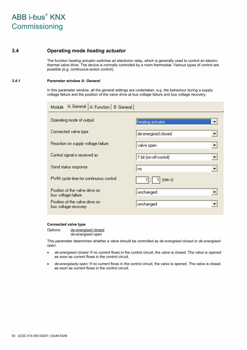
ABB i-bus® KNX Commissioning
50 2CDC 514 055 D0201 | SA/M ES/M
3.4 Operating mode heating actuator
The function heating actuator switches an electronic relay, which is generally used to control an electro-thermal valve drive. The device is normally controlled by a room thermostat. Various types of control are possible (e.g. continuous-action control).
3.4.1 Parameter window A: General
In this parameter window, all the general settings are undertaken, e.g. the behaviour during a supply voltage failure and the position of the valve drive at bus voltage failure and bus voltage recovery.
Connected valve type
Options: de-energised closed de-energised open
This parameter determines whether a valve should be controlled as de-energised closed or de-energised open.
• de-energised closed: If no current flows in the control circuit, the valve is closed. The valve is opened as soon as current flows in the control circuit.
• de-energisedy open: If no current flows in the control circuit, the valve is opened. The valve is closed as soon as current flows in the control circuit.

ABB i-bus® KNX Commissioning
SA/M ES/M | 2CDC 514 055 D0201 51
Reaction on supply voltage failure
Options: valve open valve closed
Should the supply voltage fail, the Room Controller is without function. Using this parameter, the output can be set to a defined state.
This parameter is only visible for the Switch Actuator Module SA/M. The Electronic Switch Actuator Modules ES/M 2.xx.1 always switch off on failure of the supply voltage (high-resistance).
Control signal is received as
Options: 1 bit (on-off control) 1 byte (continuous control)
The heating actuator can either be controlled via the 1 bit communication object Switch or the 1 byte communication object Control value (PWM).
• 1 bit (on-off control): The room thermostat controls the heating actuator via standard switching telegrams. An on-off control of the control value is implemented in this way. The 1 bit value can originate from pulse width modulation (PWM), which a room thermostat has calculated. During a malfunction when the control signal is not received by the room thermostat, the Switch actuator will undertake an autonomous PWM calculation. For this purpose, the SA/M uses the programmable PWM cycle time.
• 1 byte (continuous control): A value of 0…255 (corresponds to 0 %…100 %) is preset by the room thermostat. This process is also known as “continuous-action control”. At 0 %, the valve is closed, and at 100 % it is fully opened. The heating actuator controls intermediate values via pulse width modulation.
Send status response
Options: no yes (object “Status switch”)
This parameter enables the communication object Status Switch and defines its function. The communication object can have various functions depending on whether the actuator is controlled via a 1 bit or 8 bit communication object. The following table provides an overview:
1 bit (on-off-control) The communication object value is identical to the value of the communication object Switch
1 byte (continuous control) Setting “0 % = OFF, otherwise = ON”:
If the valve is fully closed, the communication object has the value 0; otherwise it has the value 1.
Setting “current status of the output”:
The communication object value corresponds to the current control of the valve. If the value is ON, the valve is open. If the value is “OFF”, the valve is closed.
Please note that this setting may result in an increased bus load!

ABB i-bus® KNX Commissioning
52 2CDC 514 055 D0201 | SA/M ES/M
PWM cycle time for continuous control
Options: [min:s]
The interpulse period of the pulse width modulation for continuous-action control is set here (corresponds to tCYC under Operating mode Heating actuator, page 84).
For 2-step control (1 bit control), the pulse width modulation is only used in fault mode, during forced operation and directly after bus voltage recovery.
Position of the valve drive on bus voltage failure
Options: unchanged 0% (closed) … 100% (open)
This parameter sets how the valve drive is controlled on bus voltage failure. The programmed value is used as the PWM cycle time.
Position of the valve drive on bus voltage recovery
Options: unchanged 0% (closed) … 100% (open)
This parameter sets how the valve drive is controlled after bus voltage recovery until the first switching or positioning telegram is received from the room thermostat. The programmed value is used as the PWM cycle time.
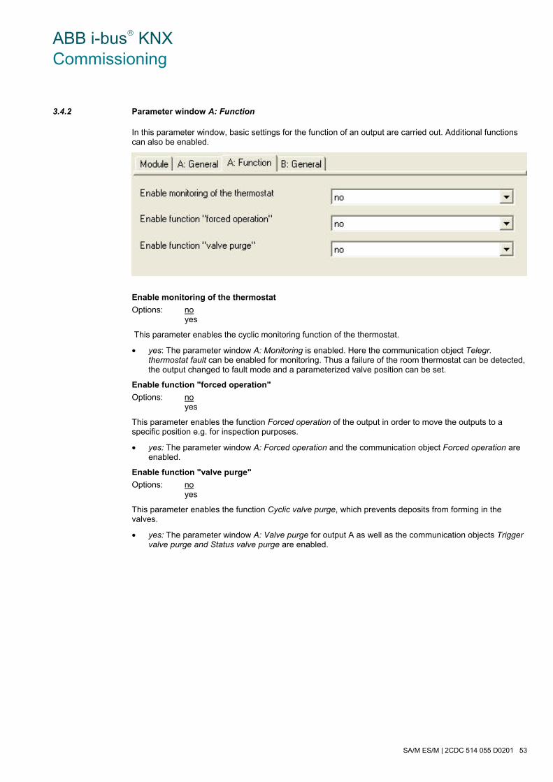
ABB i-bus® KNX Commissioning
SA/M ES/M | 2CDC 514 055 D0201 53
3.4.2 Parameter window A: Function
In this parameter window, basic settings for the function of an output are carried out. Additional functions can also be enabled.
Enable monitoring of the thermostat
Options: no yes
This parameter enables the cyclic monitoring function of the thermostat.
• yes: The parameter window A: Monitoring is enabled. Here the communication object Telegr. thermostat fault can be enabled for monitoring. Thus a failure of the room thermostat can be detected, the output changed to fault mode and a parameterized valve position can be set.
Enable function "forced operation"
Options: no yes
This parameter enables the function Forced operation of the output in order to move the outputs to a specific position e.g. for inspection purposes.
• yes: The parameter window A: Forced operation and the communication object Forced operation are enabled.
Enable function "valve purge"
Options: no yes
This parameter enables the function Cyclic valve purge, which prevents deposits from forming in the valves.
• yes: The parameter window A: Valve purge for output A as well as the communication objects Trigger valve purge and Status valve purge are enabled.
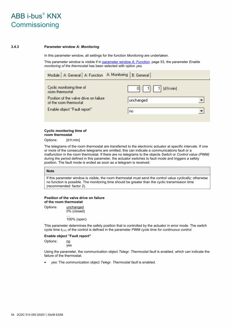
ABB i-bus® KNX Commissioning
54 2CDC 514 055 D0201 | SA/M ES/M
3.4.3 Parameter window A: Monitoring
In this parameter window, all settings for the function Monitoring are undertaken.
This parameter window is visible if in parameter window A: Function, page 53, the parameter Enable monitoring of the thermostat has been selected with option yes.
Cyclic monitoring time of room thermostat
Options: [d:h:min]
The telegrams of the room thermostat are transferred to the electronic actuator at specific intervals. If one or more of the consecutive telegrams are omitted, this can indicate a communications fault or a malfunction in the room thermostat. If there are no telegrams to the objects Switch or Control value (PWM) during the period defined in this parameter, the actuator switches to fault mode and triggers a safety position. The fault mode is ended as soon as a telegram is received.
Note
If this parameter window is visible, the room thermostat must send the control value cyclically; otherwise no function is possible. The monitoring time should be greater than the cyclic transmission time (recommended: factor 2).
Position of the valve drive on failure of the room thermostat
Options: unchanged 0% (closed) … 100% (open)
This parameter determines the safety position that is controlled by the actuator in error mode. The switch cycle time tCYC of the control is defined in the parameter PWM cycle time for continuous control.
Enable object "Fault report"
Options: no yes
Using the parameter, the communication object Telegr. Thermostat fault is enabled, which can indicate the failure of the thermostat.
• yes: The communication object Telegr. Thermostat fault is enabled.
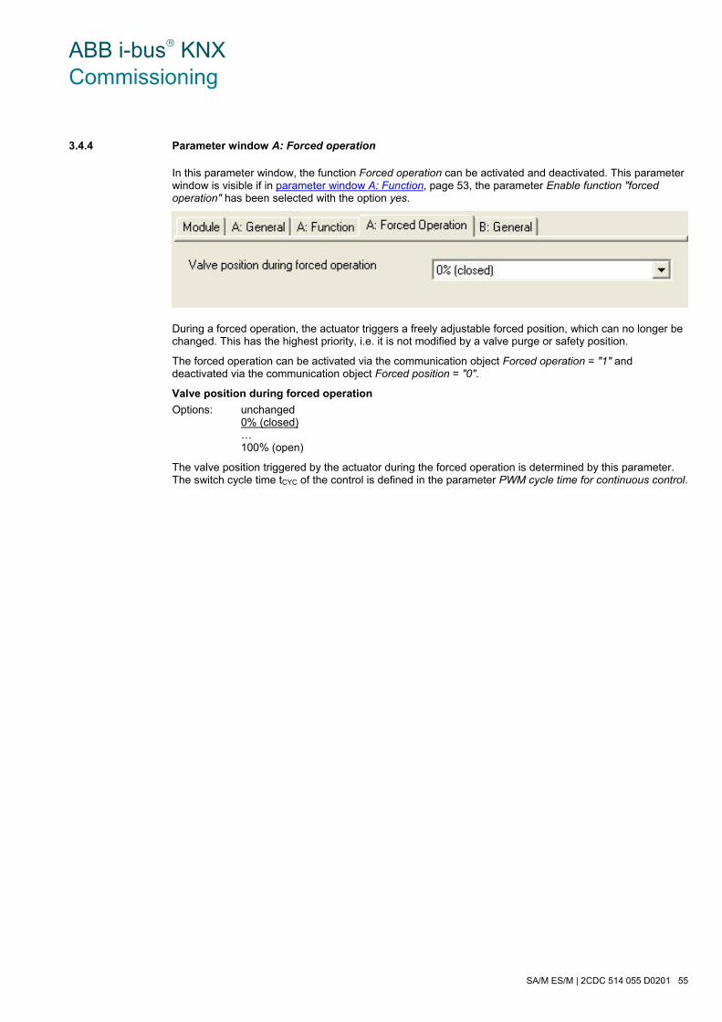
ABB i-bus® KNX Commissioning
SA/M ES/M | 2CDC 514 055 D0201 55
3.4.4 Parameter window A: Forced operation
In this parameter window, the function Forced operation can be activated and deactivated. This parameter window is visible if in parameter window A: Function, page 53, the parameter Enable function "forced operation" has been selected with the option yes.
During a forced operation, the actuator triggers a freely adjustable forced position, which can no longer be changed. This has the highest priority, i.e. it is not modified by a valve purge or safety position.
The forced operation can be activated via the communication object Forced operation = "1" and deactivated via the communication object Forced position = "0".
Valve position during forced operation
Options: unchanged 0% (closed) … 100% (open)
The valve position triggered by the actuator during the forced operation is determined by this parameter. The switch cycle time tCYC of the control is defined in the parameter PWM cycle time for continuous control.
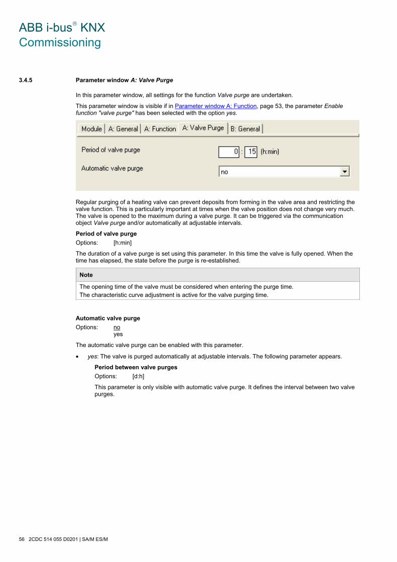
ABB i-bus® KNX Commissioning
56 2CDC 514 055 D0201 | SA/M ES/M
3.4.5 Parameter window A: Valve Purge
In this parameter window, all settings for the function Valve purge are undertaken.
This parameter window is visible if in 2Parameter window A: Function, page 53, the parameter Enable function "valve purge" has been selected with the option yes.
Regular purging of a heating valve can prevent deposits from forming in the valve area and restricting the valve function. This is particularly important at times when the valve position does not change very much. The valve is opened to the maximum during a valve purge. It can be triggered via the communication object Valve purge and/or automatically at adjustable intervals.
Period of valve purge
Options: [h:min]
The duration of a valve purge is set using this parameter. In this time the valve is fully opened. When the time has elapsed, the state before the purge is re-established.
Note
The opening time of the valve must be considered when entering the purge time. The characteristic curve adjustment is active for the valve purging time.
Automatic valve purge
Options: no yes
The automatic valve purge can be enabled with this parameter.
• yes: The valve is purged automatically at adjustable intervals. The following parameter appears.
Period between valve purges
Options: [d:h]
This parameter is only visible with automatic valve purge. It defines the interval between two valve purges.

ABB i-bus® KNX Commissioning
SA/M ES/M | 2CDC 514 055 D0201 57
3.4.6 Brief overview of the communication objects
Flags CO*No.
Function Name Data Point Type (DPT)
Length C R W T A
0 Switch Output A DPT 1.001 1 bit x x
Control value (PWM) Output A DPT 5.001 1 byte x x
1 Status Switch Output A DPT 1.001 1 bit x x
2 Not assigned
3 Forced operation Output A DPT 1.003 1 bit x x
4 Trigger valve purge Output A DPT 1.010 1 bit x x
5 Status valve purge Output A DPT 1.001 1 bit x x
6…
10 Not assigned
11 Thermostat fault Output A DPT 1.005 1 bit x x
12…
14 Not assigned
15…
28
Output B,
the same CO as output A B: see output A
29 Status byte Output A…B 1 byte x x X
*CO = communication object
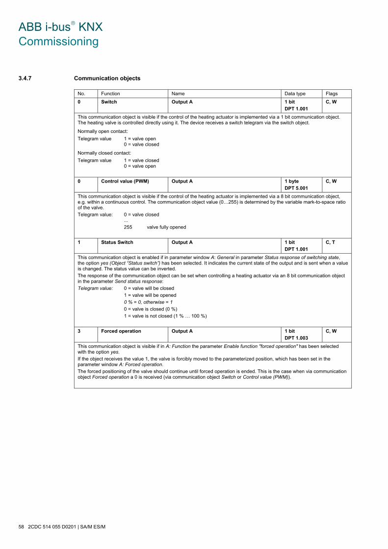
ABB i-bus® KNX Commissioning
58 2CDC 514 055 D0201 | SA/M ES/M
3.4.7 Communication objects
No. Function Name Data type Flags
0 Switch Output A 1 bit
DPT 1.001
C, W
This communication object is visible if the control of the heating actuator is implemented via a 1 bit communication object. The heating valve is controlled directly using it. The device receives a switch telegram via the switch object.
Normally open contact:
Telegram value 1 = valve open 0 = valve closed
Normally closed contact:
Telegram value 1 = valve closed 0 = valve open
0 Control value (PWM) Output A 1 byte
DPT 5.001
C, W
This communication object is visible if the control of the heating actuator is implemented via a 8 bit communication object, e.g. within a continuous control. The communication object value (0…255) is determined by the variable mark-to-space ratio of the valve.
Telegram value: 0 = valve closed ...
255 valve fully opened
1 Status Switch Output A 1 bit
DPT 1.001
C, T
This communication object is enabled if in parameter window A: General in parameter Status response of switching state, the option yes (Object “Status switch”) has been selected. It indicates the current state of the output and is sent when a value is changed. The status value can be inverted.
The response of the communication object can be set when controlling a heating actuator via an 8 bit communication object in the parameter Send status response:
Telegram value: 0 = valve will be closed
1 = valve will be opened
0 % = 0, otherwise = 1
0 = valve is closed (0 %)
1 = valve is not closed (1 % … 100 %)
3 Forced operation Output A 1 bit
DPT 1.003
C, W
This communication object is visible if in A: Function the parameter Enable function "forced operation" has been selected with the option yes.
If the object receives the value 1, the valve is forcibly moved to the parameterized position, which has been set in the parameter window A: Forced operation.
The forced positioning of the valve should continue until forced operation is ended. This is the case when via communication object Forced operation a 0 is received (via communication object Switch or Control value (PWM)).
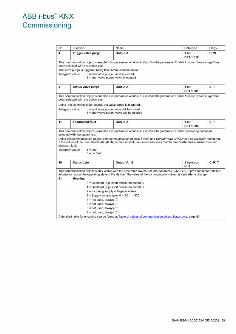
ABB i-bus® KNX Commissioning
SA/M ES/M | 2CDC 514 055 D0201 59
No. Function Name Data type Flags
4 Trigger valve purge Output A 1 bit
DPT 1.010
C, W
This communication object is enabled if in parameter window A: Function the parameter Enable function "valve purge" has been selected with the option yes.
The valve purge is triggered using this communication object.
Telegram value: 0 = end valve purge, valve is closed 1 = start valve purge, valve is opened
5 Status valve purge Output A 1 bit
DPT 1.001
C, T
This communication object is enabled if in parameter window A: Function the parameter Enable function "valve purge" has been selected with the option yes.
Using this communication object, the valve purge is triggered.
Telegram value: 0 = end valve purge, valve will be closed 1 = start valve purge, valve will be opened
11 Thermostat fault Output A 1 bit
DPT 1.005
C, T
This communication object is enabled if in parameter window A: Function the parameter Enable monitoring has been selected with the option yes.
Using this communication object, both communication objects Switch and Control value (PWM) can be cyclically monitored. If the values of the room thermostat (RTR) remain absent, the device assumes that the thermostat has a malfunction and signals a fault.
Telegram value: 1 = fault 0 = no fault
29 Status byte Output A…B 1 byte non DPT
C, R, T
This communication object is only visible with the Electronic Switch Actuator Modules ES/M 2.x.1. It provides more detailed information about the operating state of the device. The value of the communication object is sent after a change.
Bit Meaning
0 = Overload (e.g. short circuit) on output A
1 = Overload (e.g. short circuit) on output B
2 = Incoming supply voltage available
3 = Supply voltage type: 0 = AC; 1 = DC
4 = not used, always “0”
5 = not used, always “0”
6 = not used, always “0”
7 = not used, always “0”
A detailed table for encoding can be found at Table of values of communication object Status byte, page 93.
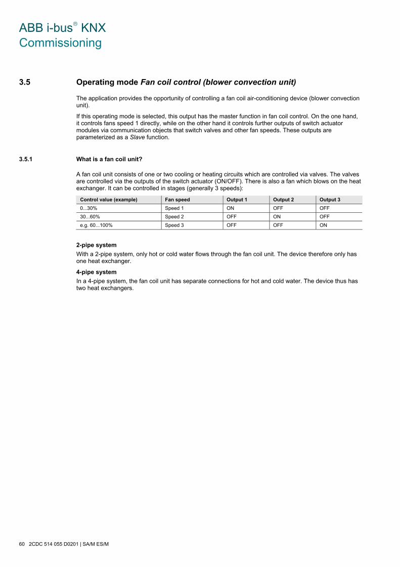
ABB i-bus® KNX Commissioning
60 2CDC 514 055 D0201 | SA/M ES/M
3.5 Operating mode Fan coil control (blower convection unit)
The application provides the opportunity of controlling a fan coil air-conditioning device (blower convection unit).
If this operating mode is selected, this output has the master function in fan coil control. On the one hand, it controls fans speed 1 directly, while on the other hand it controls further outputs of switch actuator modules via communication objects that switch valves and other fan speeds. These outputs are parameterized as a Slave function.
3.5.1 What is a fan coil unit?
A fan coil unit consists of one or two cooling or heating circuits which are controlled via valves. The valves are controlled via the outputs of the switch actuator (ON/OFF). There is also a fan which blows on the heat exchanger. It can be controlled in stages (generally 3 speeds):
Control value (example) Fan speed Output 1 Output 2 Output 3
0...30% Speed 1 ON OFF OFF
30...60% Speed 2 OFF ON OFF
e.g. 60...100% Speed 3 OFF OFF ON
2-pipe system
With a 2-pipe system, only hot or cold water flows through the fan coil unit. The device therefore only has one heat exchanger.
4-pipe system
In a 4-pipe system, the fan coil unit has separate connections for hot and cold water. The device thus has two heat exchangers.

ABB i-bus® KNX Commissioning
SA/M ES/M | 2CDC 514 055 D0201 61
3.5.2 Parameter window A: General
In this parameter window, all general settings for fan coil control are undertaken.
Function of output when control is active
Options: master slave
Here you can set whether the output operates as a Master or Slave in fan coil control mode.
There can only be one output with the master function per fan coil unit. This controls fan speed 1. The master controls valve drives or further fan speeds via communication objects. These outputs must then be parameterized with the Slave function.
Important
Outputs with the slave function should be parameterized as such. If parameterized, e.g. as a Switch actuator, there is a danger that more than one output is closed under unfavourable conditions. The fan motor for example can be damaged as a result.
Outputs with the slave function are only controlled via the communication object Fan coil slave. The following parameters are only visible in the Master setting.
Status response of switching state
Options: no yes
• yes: The communication object Status switch is enabled. This reports back the output on the bus.

ABB i-bus® KNX Commissioning
62 2CDC 514 055 D0201 | SA/M ES/M
Waiting time for switching between two speeds
Options: [s:ms]
The operating time is delayed to enable an idle period, when switching over the motor or valve, or to prevent the period that they are switched on/off from being too short. The value range can be set from 500 ms to 1 min.
Type of fan coil unit
Options: 4 pipe system 2 pipe system
This parameter defines type of fan coil unit.
• 4 pipe system: The fan coil unit has separate connections for hot or cold water. The device thus has two heat exchangers.
• 2 pipe system: Only hot or cold water flows with a fan coil unit. The device therefore only has one heat exchanger. The following parameter appears:
Operation mode
Options: heating and cooling heating only cooling only
The operating mode can be set using this parameter.
• heating and cooling: The following parameter appears:
Function of object “Toggle heating/cooling“
Options: normal (heating = 0, cooling = 1) inverted (heating = 1, cooling = 0)
This parameter determines the assignment of the telegram value. The values can be inverted. The assignment of the function to the value is determined by the thermostat.
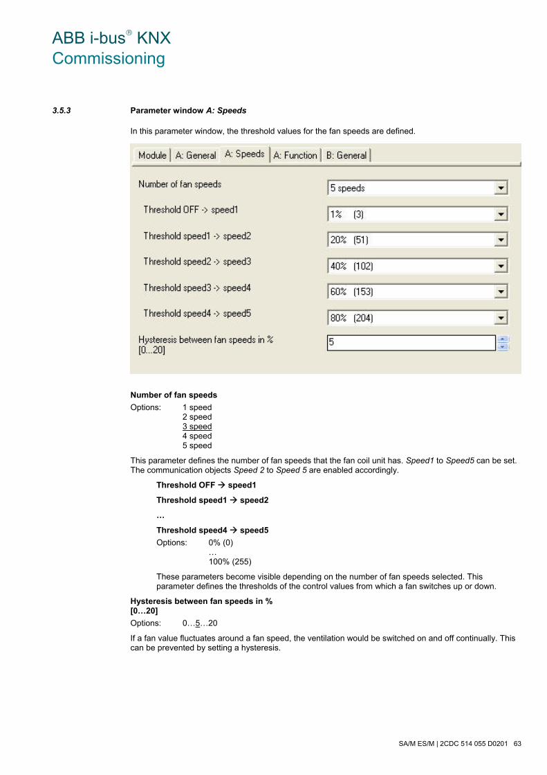
ABB i-bus® KNX Commissioning
SA/M ES/M | 2CDC 514 055 D0201 63
3.5.3 Parameter window A: Speeds
In this parameter window, the threshold values for the fan speeds are defined.
Number of fan speeds
Options: 1 speed 2 speed 3 speed 4 speed 5 speed
This parameter defines the number of fan speeds that the fan coil unit has. Speed1 to Speed5 can be set. The communication objects Speed 2 to Speed 5 are enabled accordingly.
Threshold OFF speed1
Threshold speed1 speed2
…
Threshold speed4 speed5
Options: 0% (0) … 100% (255)
These parameters become visible depending on the number of fan speeds selected. This parameter defines the thresholds of the control values from which a fan switches up or down.
Hysteresis between fan speeds in % [0…20]
Options: 0…5…20
If a fan value fluctuates around a fan speed, the ventilation would be switched on and off continually. This can be prevented by setting a hysteresis.
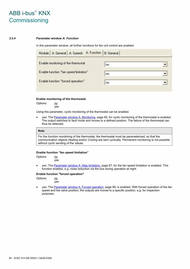
ABB i-bus® KNX Commissioning
64 2CDC 514 055 D0201 | SA/M ES/M
3.5.4 Parameter window A: Function
In this parameter window, all further functions for fan coil control are enabled.
Enable monitoring of the thermostat
Options: no yes
Using this parameter, cyclic monitoring of the thermostat can be enabled.
• yes: The Parameter window A: Monitoring, page 65, for cyclic monitoring of the thermostat is enabled. The output switches to fault mode and moves to a defined position. The failure of the thermostat can thus be detected.
Note
For the function monitoring of the thermostat, the thermostat must be parameterized, so that the communication objects Heating and/or Cooling are sent cyclically. Permanent monitoring is not possible without cyclic sending of the values.
Enable function “fan speed limitation”
Options: no yes
• yes: The Parameter window A: Step limitation, page 67, for the fan speed limitation is enabled. This function enables, e.g. noise reduction via the bus during operation at night.
Enable function "forced operation"
Options: no yes
• yes: The Parameter window A: Forced operation, page 68, is enabled. With forced operation of the fan speed and the valve position, the outputs are moved to a specific position, e.g. for inspection purposes.

ABB i-bus® KNX Commissioning
SA/M ES/M | 2CDC 514 055 D0201 65
3.5.5 Parameter window A: Monitoring
This parameter window is visible if in parameter window A: Function, page 64, in the parameter Function monitoring of the thermostat, the option yes has been selected. The cyclic monitoring of the thermostat is implemented via the communication objects control value heating and control value cooling. As soon as the communication objects are not received for a certain period, the device switches to fault mode (communication object Fault = 1).
Note
Cyclic monitoring may only be enabled if the room thermostat sends the communication objects Heating and/or Cooling cyclically. Permanent monitoring is not possible without cyclic sending.
Cyclic monitoring time of room thermostat
Options: [d:h:min]
This parameter defines the cyclic monitoring time.
Fan speed during fault of room thermostat”
Options: OFF (0) step 1 ... step 5
This parameter defines which fan speed and valve position is triggered during fault mode.
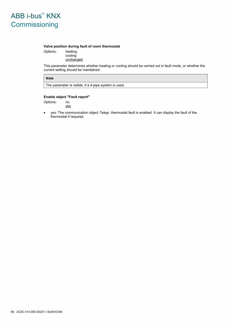
ABB i-bus® KNX Commissioning
66 2CDC 514 055 D0201 | SA/M ES/M
Valve position during fault of room thermostat
Options: heating cooling unchanged
This parameter determines whether heating or cooling should be carried out in fault mode, or whether the current setting should be maintained.
Note
The parameter is visible, if a 4-pipe system is used.
Enable object "Fault report"
Options: no yes
• yes: The communication object Telegr. thermostat fault is enabled. It can display the fault of the thermostat if required.
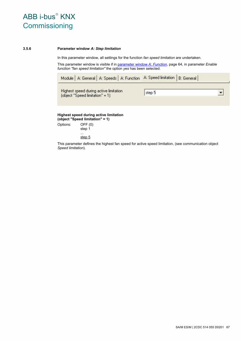
ABB i-bus® KNX Commissioning
SA/M ES/M | 2CDC 514 055 D0201 67
3.5.6 Parameter window A: Step limitation
In this parameter window, all settings for the function fan speed limitation are undertaken.
This parameter window is visible if in parameter window A: Function, page 64, in parameter Enable function "fan speed limitation" the option yes has been selected.
Highest speed during active limitation (object "Speed limitation" = 1)
Options: OFF (0) step 1 ... step 5
This parameter defines the highest fan speed for active speed limitation, (see communication object Speed limitation).

ABB i-bus® KNX Commissioning
68 2CDC 514 055 D0201 | SA/M ES/M
3.5.7 Parameter window A: Forced operation
In this parameter window, all settings for the function Forced operation are undertaken.
This parameter window is visible if in parameter window A: Function, page 64, the parameter Enable function "forced operation" has been enabled.
During a forced operation, the actuator triggers a freely adjustable forced position. This has the highest priority, i.e. it is not modified by a valve purge or safety position. The forced operation can be activated via the communication object Forced operation = ON and deactivated via Forced operation = OFF.
Fan speed during forced operation
Options: OFF (0) step 1 ... step 5
This parameter defines which fan speed and valve position are triggered during the forced operation.
Valve position during forced positioning
Options: heating cooling unchanged
The valve position triggered by the actuator during the forced operation is determined by this parameter. The switch cycle time tCYC of the control is defined in the parameter PWM cycle time for continuous control.

ABB i-bus® KNX Commissioning
SA/M ES/M | 2CDC 514 055 D0201 69
3.5.8 Brief overview of the communication objects
Flags CO*No.
Function Name Data Point Type (DPT)
Length C R W T A
0 Control value heating Output A, Master DPT 5.001 1 byte x x
1 Control value cooling Output A, Master DPT 5.001 1 byte x x
2 Step limiting Output A, Master DPT 1.002 1 bit x x
3 Forced operation Output A, Master DPT 1.003 1 bit x x
4 Toggle between heat and cool Output A, Master DPT 1.001 1 bit x x
5 Slave fan speed 2 Output A, Master DPT 1.001 1 bit x x x
6 Slave fan speed 3 Output A, Master DPT 1.001 1 bit x x x
7 Slave fan speed 4 Output A, Master DPT 1.001 1 bit x x x
8 Slave fan speed 5 Output A, Master DPT 1.001 1 bit x x x
Slave valve Output A, Master DPT 1.001 1 bit x x x 9
Slave valve heating Output A, Master DPT 1.001 1 bit x x x
10 Slave valve cooling Output A, Master DPT 1.001 1 bit x x x
11 Thermostat fault Output A, Master DPT 1.005 1 bit x x
12 Status Switch Output A, Master DPT 1.001 1 bit x x
13…
14 Not assigned
15…
28
Output B,
the same CO as output A B: see output A
29 Status byte Output A…B 1 byte x x X
*CO = communication object
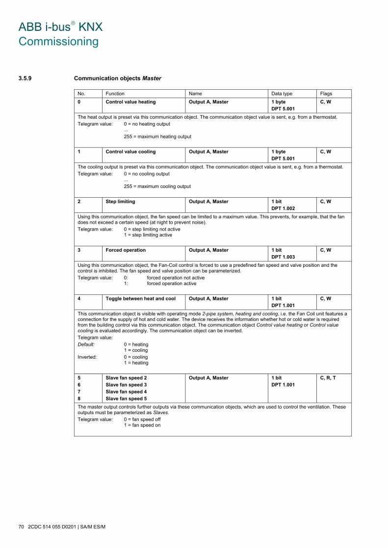
ABB i-bus® KNX Commissioning
70 2CDC 514 055 D0201 | SA/M ES/M
3.5.9 Communication objects Master
No. Function Name Data type Flags
0 Control value heating Output A, Master 1 byte
DPT 5.001
C, W
The heat output is preset via this communication object. The communication object value is sent, e.g. from a thermostat.
Telegram value: 0 = no heating output ...
255 = maximum heating output
1 Control value cooling Output A, Master 1 byte
DPT 5.001
C, W
The cooling output is preset via this communication object. The communication object value is sent, e.g. from a thermostat.
Telegram value: 0 = no cooling output ...
255 = maximum cooling output
2 Step limiting Output A, Master 1 bit
DPT 1.002
C, W
Using this communication object, the fan speed can be limited to a maximum value. This prevents, for example, that the fan does not exceed a certain speed (at night to prevent noise).
Telegram value: 0 = step limiting not active 1 = step limiting active
3 Forced operation Output A, Master 1 bit
DPT 1.003
C, W
Using this communication object, the Fan-Coil control is forced to use a predefined fan speed and valve position and the control is inhibited. The fan speed and valve position can be parameterized.
Telegram value: 0: forced operation not active 1: forced operation active
4 Toggle between heat and cool Output A, Master 1 bit
DPT 1.001
C, W
This communication object is visible with operating mode 2-pipe system, heating and cooling, i.e. the Fan Coil unit features a connection for the supply of hot and cold water. The device receives the information whether hot or cold water is required from the building control via this communication object. The communication object Control value heating or Control value cooling is evaluated accordingly. The communication object can be inverted.
Telegram value:
Default: 0 = heating 1 = cooling
Inverted: 0 = cooling 1 = heating
5
6
7
8
Slave fan speed 2
Slave fan speed 3
Slave fan speed 4
Slave fan speed 5
Output A, Master 1 bit
DPT 1.001
C, R, T
The master output controls further outputs via these communication objects, which are used to control the ventilation. These outputs must be parameterized as Slaves.
Telegram value: 0 = fan speed off 1 = fan speed on

ABB i-bus® KNX Commissioning
SA/M ES/M | 2CDC 514 055 D0201 71
No. Function Name Data type Flags
9 Slave valve Output A, Master 1 bit
DPT 1.001
C, R, T
This communication object is visible when controlling a 2-pipe system, i.e. there is only one valve. The communication object controls a further output that controls the valve. The output must be parameterized as a Slave. As soon as the fan operates with at least the first speed, the communication object value = 1, otherwise it is 0.
Telegram value: 0 = valve closed 1 = valve opened
9
10
Slave valve heating
Slave valve cooling
Output A, Master 1 bit
DPT 1.001
C, R, T
These communication objects are visible when controlling a 4-pipe system, i.e. there are two valves for heating and cooling.
With these communication objects, the master controls two switch outputs for control of the heating and cooling valves.
Slave valve heating has the value 1, if the room thermostat has issued the telegram for heating via the communication object Control value heating (Control value heating ≥ threshold for fan speed 1).
Slave valve cooling has the value 1, if the room thermostat has issued the telegram for cooling via the communication object Control value cooling (Control value cooling ≥ threshold for fan speed 1).
Either Slave valve heating or Slave valve cooling can have the value 1. Should a simultaneous telegram (malfunction) from the thermostat be received for both heating and cooling, heating has priority.
Telegram value: 0 = valve closed 1 = valve opened
11 Thermostat fault Output A, Master 1 bit
DPT 1.005
C, T
This communication object indicates a possible fault in the room thermostat. Should the communication object value Control value heating or Control value cooling remain absent for a programmable time, a fault is assumed in the room thermometer and the Fan Coil control reports a fault and moves to the safety position.
Telegram value: 0 = no fault 1 = fault
12 Status Switch Output A 1 bit
DPT 1.001
C, T
This communication object displays the current state of the output.
Telegram value: 0 = relay opened 1 = relay is closed
29 Status byte Output A…B 1 byte
non DPT
C, R, T
This communication object is only visible with the Electronic Switch Actuator Modules ES/M 2.x.1. It provides more detailed information about the operating state of the device. The value of the communication object is sent after a change.
Bit Meaning
0 = Overload (e.g. short circuit) on output A
1 = Overload (e.g. short circuit) on output B
2 = Incoming supply voltage available
3 = Supply voltage type: 0 = AC; 1 = DC
4 = not used, always “0”
5 = not used, always “0”
6 = not used, always “0”
7 = not used, always “0”
A detailed table for encoding can be found at A.1, page 93.
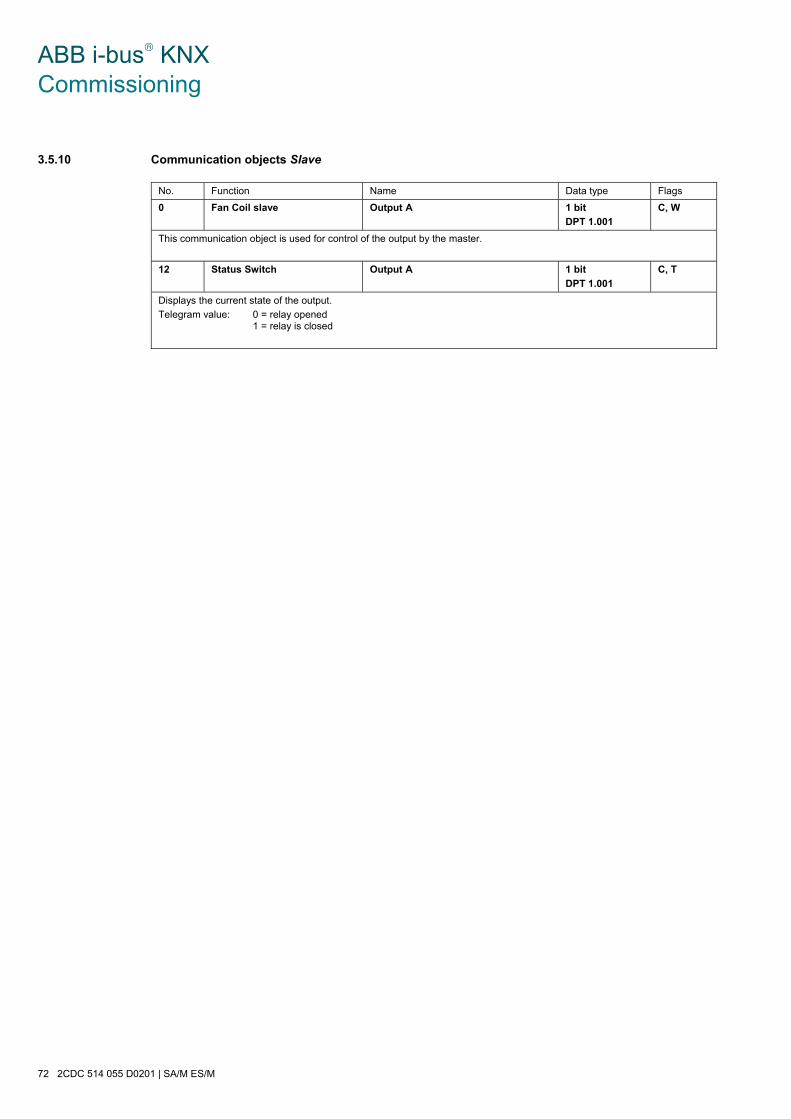
ABB i-bus® KNX Commissioning
72 2CDC 514 055 D0201 | SA/M ES/M
3.5.10 Communication objects Slave
No. Function Name Data type Flags
0 Fan Coil slave Output A 1 bit
DPT 1.001
C, W
This communication object is used for control of the output by the master.
12 Status Switch Output A 1 bit
DPT 1.001
C, T
Displays the current state of the output.
Telegram value: 0 = relay opened 1 = relay is closed
ABB i-bus® KNX Planning and application
SA/M ES/M | 2CDC 514 055 D0201 73
4 Planning and application
4.1 The three operating modes
It is possible to choose between three operating modes for each output:
1) Switch actuator
This function is used for normal switching, e.g. of lighting. The output is controlled directly via the communication object Switch. A large number of additional functions are possible.
For further information see: Operating mode Switch actuator, page 74
2) Heating actuator
In this function, the output is used to control heating valves, e.g. in an individual room temperature control system. A room thermostat sends a control value, which the output uses to control the valve (e.g. as PWM or 2-step control).
For further information see: Operating mode Heating actuator, page 84
3) Fan coil control (blower convector)
This function is used to control a fan coil unit for air conditioning in a room, e.g. in an individual room temperature control system.
The function is as follows: An external room thermostat determines the setpoint value (0…255). The fan speed and the setpoint value of the fan coil unit are to be controlled depending on this setpoint value. Several outputs are required for control and the output therefore controls further outputs (Slaves) as a Master via the bus. The master output itself controls fan speed 1.
For further information see: Operating mode Fan coil control, page 86

ABB i-bus® KNX Planning and application
74 2CDC 514 055 D0201 | SA/M ES/M
4.2 Operating mode Switch actuator
4.2.1 Time functions
Different functions can be realised using the function time:
• staircase lighting function
• ON and OFF delay
• flashing
4.2.1.1 Staircase lighting function
The output switches off automatically after the staircase lighting time TON. With each telegram with value 1, the time restarts (retrigger function), if the parameter Extending staircase lighting by multiple operation ("pumping up") is set to yes in the parameter window A: Time to no, not retriggerable.
This corresponds with the basic response of the function Staircase lighting, as long as a warning is not parameterized.
Output
Communication objectSwitch
ON
OFF
TON
1 1
Communication objectWarning stair lighting 0

ABB i-bus® KNX Planning and application
SA/M ES/M | 2CDC 514 055 D0201 75
Warning
An additional warning function enables the user to be warned in good time, before the staircase lighting time elapses. It can be carried out by switching the output on/off briefly or by sending a communication object.
The warning time TWARN extends the ON phase. At the start of the warning time, the output can be briefly switched on and off, and/or the communication object Warning stair lighting can be written with a value 1. The output is switched off briefly for the period TWARN, before the staircase lighting time TON elapses and the communication object Warning stair lighting is sent. As a result, for example, half of the lighting is switched off and a LED is switched on as a warning.
The entire staircase lighting time, in which the staircase lighting is on, corresponds with the time period TON plus TWARN.
Retriggering
Via “pumping up”, that is actuation of the push button several times in succession, the user can adapt the staircase lighting to their current needs. The maximum duration of the staircase lighting time can be set in the parameters.
If the device receives a further ON telegram when the staircase lighting is switched on, the staircase lighting time is added to the remaining period.
The warning time does not change due to "Pumping up" and is added to the extended (x-fold TON) ON time.
Application examples:
• Lighting control in stairwells
• Monitoring of telegrams
Output
Communication objectSwitch
ON
OFF
TON
1
Communication objectWarning stair lighting 0
1
1TWarn
Output
Communication objectSwitch
ON
OFF
TONTONTON
3 x 1
Communication objectWarning stair lighting 0
1
TWarn

ABB i-bus® KNX Planning and application
76 2CDC 514 055 D0201 | SA/M ES/M
4.2.1.2 ON and OFF delay
The ON and OFF delay delays switch on or switch off of the output.
The delay time TD1 or TD0 starts after a switch telegram, and after it has timed out, the output executes the switch telegram.
If a new ON telegram with the value 1 is received during the switch on delay, the time of the switch on delay starts again. The same applies to switch off for the switch off delay. If a new OFF telegram with the value 0 is received during the switch off delay, the time for the switch off delay starts again.
Note
If the device receives an OFF telegram during the switch on delay TD1, an ON telegram is disregarded.
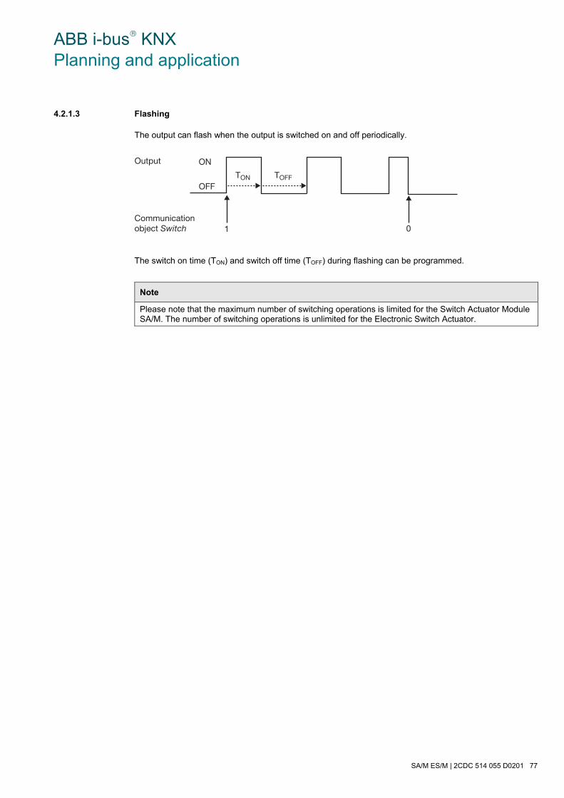
ABB i-bus® KNX Planning and application
SA/M ES/M | 2CDC 514 055 D0201 77
4.2.1.3 Flashing
The output can flash when the output is switched on and off periodically.
The switch on time (TON) and switch off time (TOFF) during flashing can be programmed.
Note
Please note that the maximum number of switching operations is limited for the Switch Actuator Module SA/M. The number of switching operations is unlimited for the Electronic Switch Actuator.
Output
Communication object Switch
ON
OFFTON
1 0
TOFF
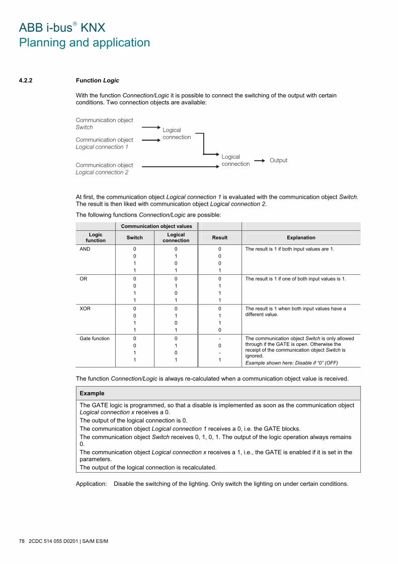
ABB i-bus® KNX Planning and application
78 2CDC 514 055 D0201 | SA/M ES/M
4.2.2 Function Logic
With the function Connection/Logic it is possible to connect the switching of the output with certain conditions. Two connection objects are available:
At first, the communication object Logical connection 1 is evaluated with the communication object Switch. The result is then liked with communication object Logical connection 2.
The following functions Connection/Logic are possible:
Communication object values
Logic function
Switch Logical
connection Result Explanation
AND 0
0
1
1
0
1
0
1
0
0
0
1
The result is 1 if both input values are 1.
OR 0
0
1
1
0
1
0
1
0
1
1
1
The result is 1 if one of both input values is 1.
XOR 0
0
1
1
0
1
0
1
0
1
1
0
The result is 1 when both input values have a different value.
Gate function 0
0
1
1
0
1
0
1
-
0
-
1
The communication object Switch is only allowed through if the GATE is open. Otherwise the receipt of the communication object Switch is ignored.
Example shown here: Disable if “0” (OFF)
The function Connection/Logic is always re-calculated when a communication object value is received.
Example
The GATE logic is programmed, so that a disable is implemented as soon as the communication object Logical connection x receives a 0. The output of the logical connection is 0. The communication object Logical connection 1 receives a 0, i.e. the GATE blocks. The communication object Switch receives 0, 1, 0, 1. The output of the logic operation always remains 0. The communication object Logical connection x receives a 1, i.e., the GATE is enabled if it is set in the parameters. The output of the logical connection is recalculated.
Application: Disable the switching of the lighting. Only switch the lighting on under certain conditions.
Communication objectSwitch
Communication objectLogical connection 1
Logicalconnection
OutputLogicalconnectionCommunication object
Logical connection 2

ABB i-bus® KNX Planning and application
SA/M ES/M | 2CDC 514 055 D0201 79
4.2.3 Function Preset
A parameterizable switching state can be retrieved with the help of presets. Light scenes can therefore be implemented, for example, with a 1 bit communication object.
Retrieve preset
Switch states (preset values) can be retrieved via the communication objects Recall preset 1/2. A maximum of two preset values are available for each output:
Action Telegram
Recall preset 1 Communication object Recall Preset 1/2 = 0
Recall preset 2 Communication object Recall Preset 1/2 = 1
Recall preset 3 Communication object Recall Preset 3/4 = 0
Recall preset 4 Communication object Recall Preset 3/4 = 1
Store preset
The current switching state is stored as a new preset value via the object Set preset …. The user can, for example, adapt a light scene in this way. The presets are stored via the following values:
Action Telegram
Save preset 1 Communication object Set preset 1/2 = 0
Save preset 2 Communication object Set preset 1/2 = 1
Save preset 3 Communication object Set preset 3/4 = 0
Save preset 4 Communication object Set preset 3/4 = 1
Button push
call preset
OFF
Actuator 1
ON
Actuator 2
ON
Actuator 3
Button push
save preset
ON
Actuator 1
OFF
Actuator 2
ON
Actuator 3
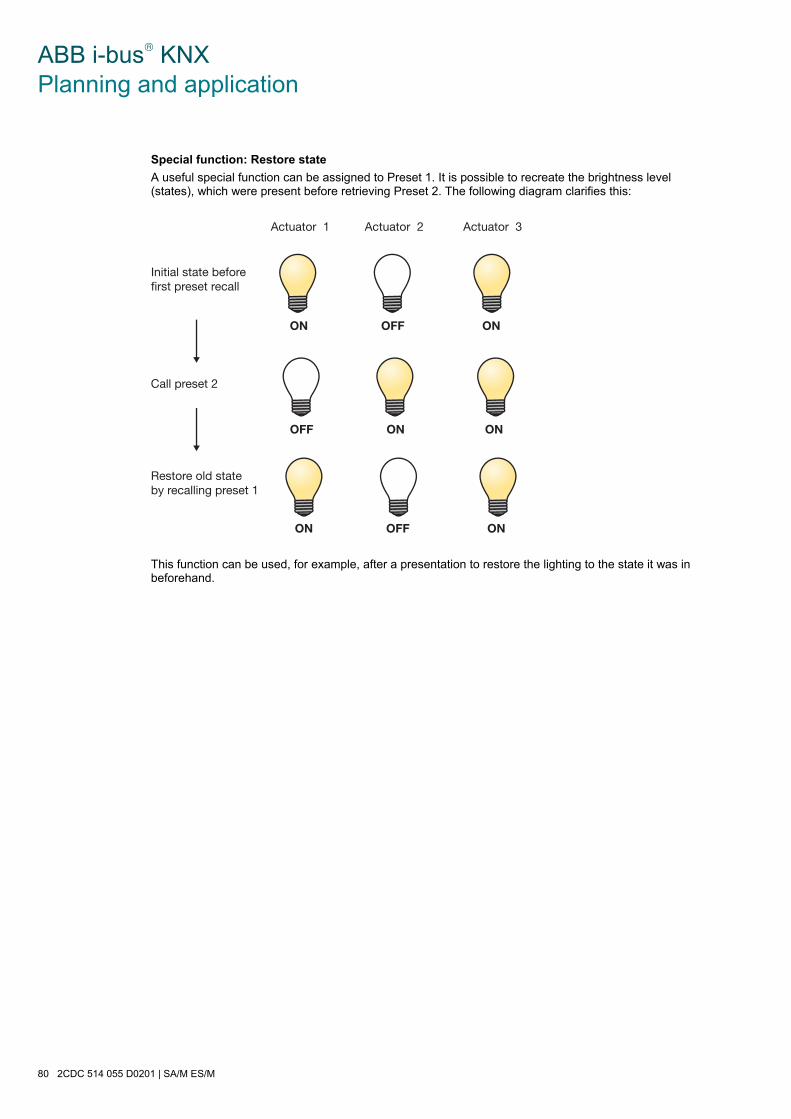
ABB i-bus® KNX Planning and application
80 2CDC 514 055 D0201 | SA/M ES/M
Special function: Restore state
A useful special function can be assigned to Preset 1. It is possible to recreate the brightness level (states), which were present before retrieving Preset 2. The following diagram clarifies this:
This function can be used, for example, after a presentation to restore the lighting to the state it was in beforehand.
Initial state before first preset recall
ON OFF ON
Actuator 1 Actuator 2 Actuator 3
ON OFF ON
OFF ON ON
Call preset 2
Restore old state by recalling preset 1
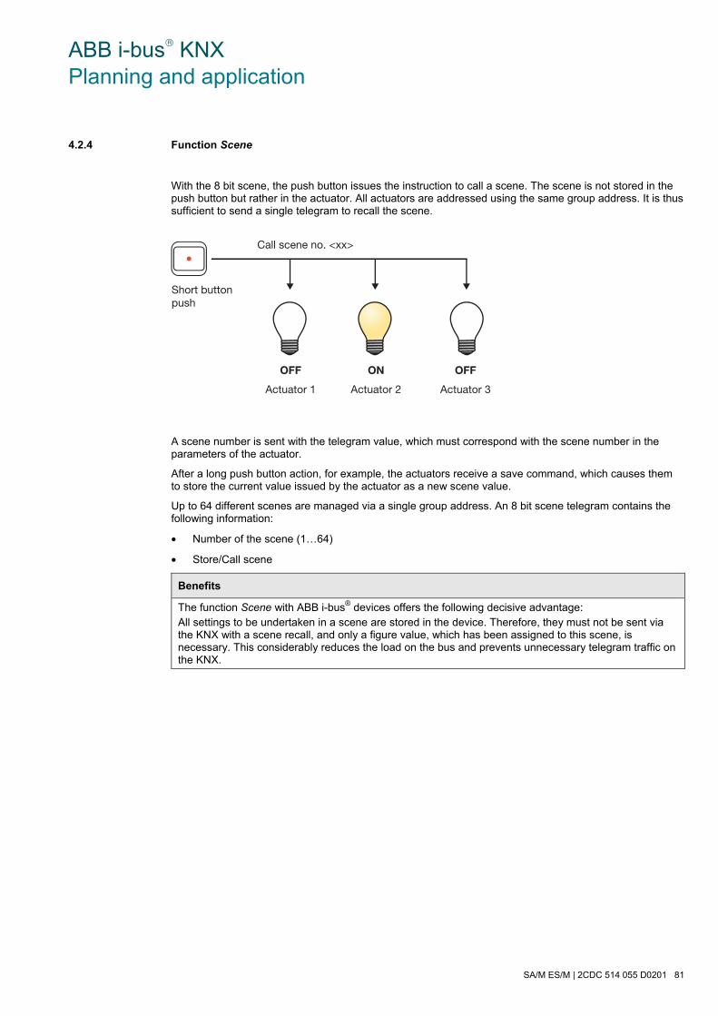
ABB i-bus® KNX Planning and application
SA/M ES/M | 2CDC 514 055 D0201 81
4.2.4 Function Scene
With the 8 bit scene, the push button issues the instruction to call a scene. The scene is not stored in the push button but rather in the actuator. All actuators are addressed using the same group address. It is thus sufficient to send a single telegram to recall the scene.
A scene number is sent with the telegram value, which must correspond with the scene number in the parameters of the actuator.
After a long push button action, for example, the actuators receive a save command, which causes them to store the current value issued by the actuator as a new scene value.
Up to 64 different scenes are managed via a single group address. An 8 bit scene telegram contains the following information:
• Number of the scene (1…64)
• Store/Call scene
Benefits
The function Scene with ABB i-bus® devices offers the following decisive advantage: All settings to be undertaken in a scene are stored in the device. Therefore, they must not be sent via the KNX with a scene recall, and only a figure value, which has been assigned to this scene, is necessary. This considerably reduces the load on the bus and prevents unnecessary telegram traffic on the KNX.
Short buttonpush
Call scene no. <xx>
OFF
Actuator 1
ON
Actuator 2
OFF
Actuator 3
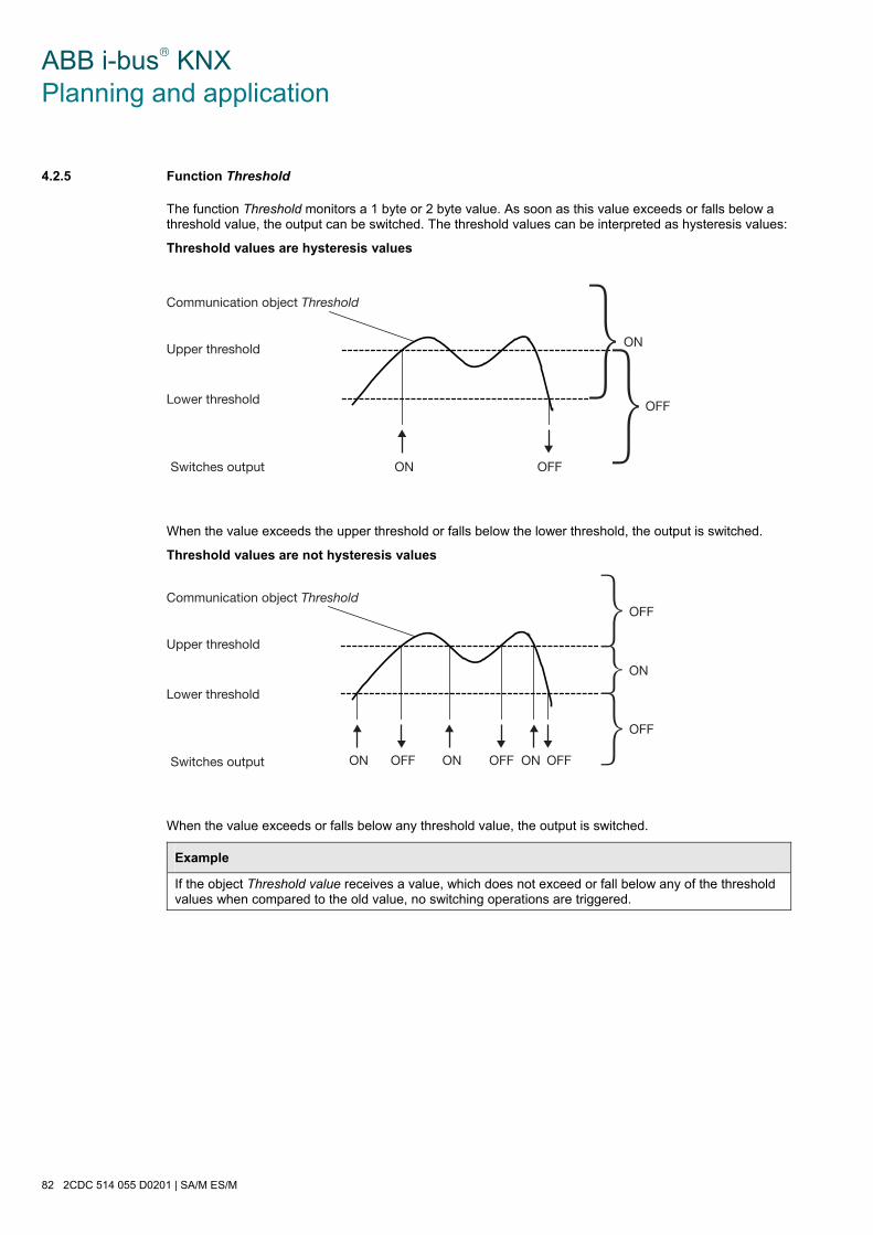
ABB i-bus® KNX Planning and application
82 2CDC 514 055 D0201 | SA/M ES/M
4.2.5 Function Threshold
The function Threshold monitors a 1 byte or 2 byte value. As soon as this value exceeds or falls below a threshold value, the output can be switched. The threshold values can be interpreted as hysteresis values:
Threshold values are hysteresis values
When the value exceeds the upper threshold or falls below the lower threshold, the output is switched.
Threshold values are not hysteresis values
When the value exceeds or falls below any threshold value, the output is switched.
Example
If the object Threshold value receives a value, which does not exceed or fall below any of the threshold values when compared to the old value, no switching operations are triggered.
Communication object Threshold
Upper threshold
Lower threshold
ON OFFSwitches output
{{ON
OFF
Communication object Threshold
Upper threshold
Lower threshold
ON OFFSwitches output ON ONOFF OFF
ON
OFF
{
{{
OFF

ABB i-bus® KNX Planning and application
SA/M ES/M | 2CDC 514 055 D0201 83
4.2.6 Function chart
The following illustration indicates the sequence, in which the functions are processed.
Send telegram
Example
On receipt of a Logical connection object, the linking logic is evaluated first of all. The result is analysed by the time function; when the staircase lighting function is active, this can result in the staircase lighting being switched on.
The forced operation has the highest priority, as it is evaluated last of all the functions.
Communication objects - Switch - Retrieve preset - Retrieve Scene - Threshold value
Communication objects - Logical Connection 1 - Logical Connection 2
Cyclic monitoring of the communication object Switch
Communication object Priority/Forced operation
Switch relay
Switch telegram
Evaluate Connection / Logic
Evaluate forced operation
Evaluate time function
Evaluate relay operation
Evaluate Cyclic monitoring of the com-munication object Switch
Staircase lighting functionON and OFF delayFlashing
Fault mode if communicationobject Switch is omitted
Forced operation active / inactive
Normally opened contactNormally closed contact
ANDORXORGate
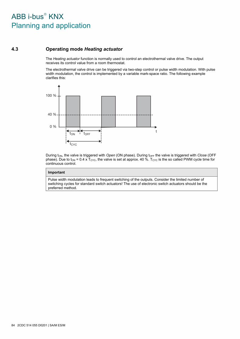
ABB i-bus® KNX Planning and application
84 2CDC 514 055 D0201 | SA/M ES/M
4.3 Operating mode Heating actuator
The Heating actuator function is normally used to control an electrothermal valve drive. The output receives its control value from a room thermostat.
The electrothermal valve drive can be triggered via two-step control or pulse width modulation. With pulse width modulation, the control is implemented by a variable mark-space ratio. The following example clarifies this:
During tON, the valve is triggered with Open (ON phase). During tOFF the valve is triggered with Close (OFF phase). Due to tON = 0.4 x TCYC, the valve is set at approx. 40 %. TCYC is the so called PWM cycle time for continuous control.
Important
Pulse width modulation leads to frequent switching of the outputs. Consider the limited number of switching cycles for standard switch actuators! The use of electronic switch actuators should be the preferred method.
100 %
40 %
0 %ttON tOFF
tCYC
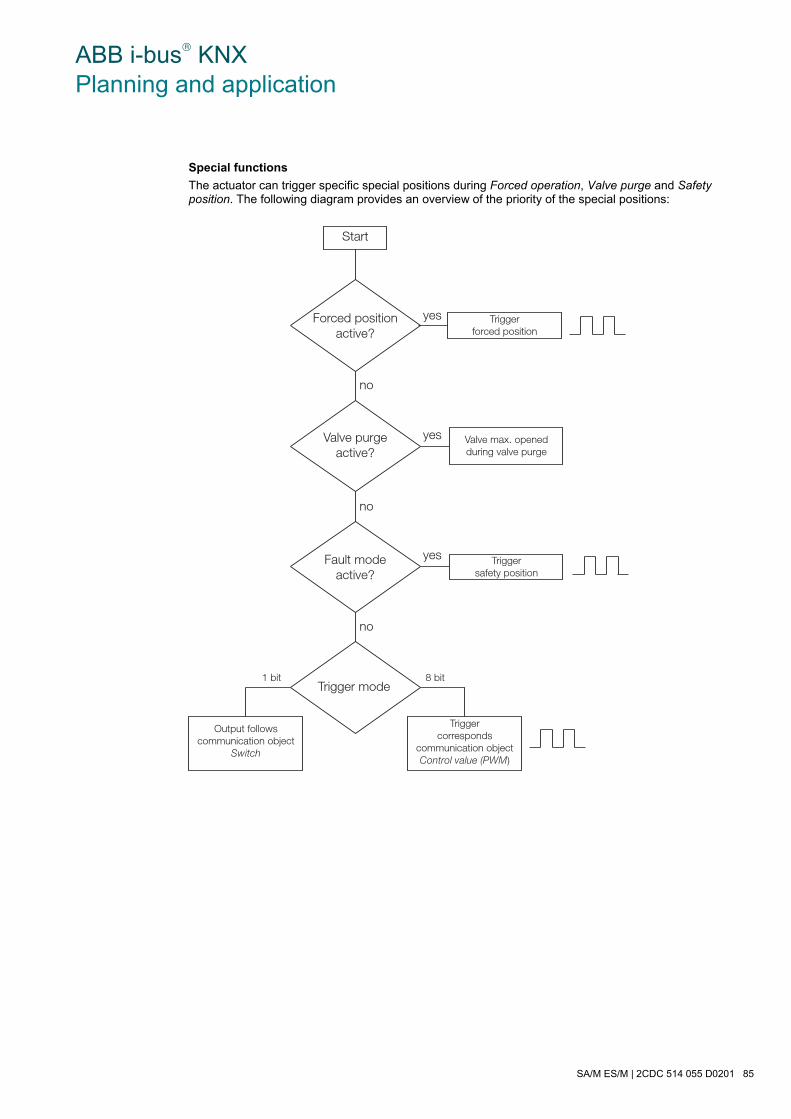
ABB i-bus® KNX Planning and application
SA/M ES/M | 2CDC 514 055 D0201 85
Special functions
The actuator can trigger specific special positions during Forced operation, Valve purge and Safety position. The following diagram provides an overview of the priority of the special positions:
Start
Forced positionactive?
Valve purgeactive?
Fault modeactive?
Trigger mode
Output followscommunication object
Switch
Triggercorresponds
communication objectControl value (PWM)
Valve max. openedduring valve purge
Triggersafety position
Triggerforced position
8 bit1 bit
yes
yes
no
no
no
yes
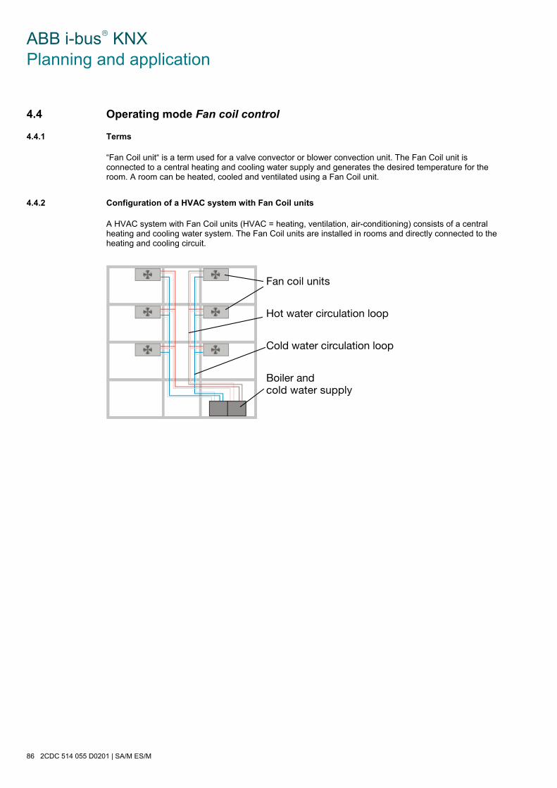
ABB i-bus® KNX Planning and application
86 2CDC 514 055 D0201 | SA/M ES/M
4.4 Operating mode Fan coil control
4.4.1 Terms
“Fan Coil unit“ is a term used for a valve convector or blower convection unit. The Fan Coil unit is connected to a central heating and cooling water supply and generates the desired temperature for the room. A room can be heated, cooled and ventilated using a Fan Coil unit.
4.4.2 Configuration of a HVAC system with Fan Coil units
A HVAC system with Fan Coil units (HVAC = heating, ventilation, air-conditioning) consists of a central heating and cooling water system. The Fan Coil units are installed in rooms and directly connected to the heating and cooling circuit.
������������
����������������������
�����������������������
�����������������������

ABB i-bus® KNX Planning and application
SA/M ES/M | 2CDC 514 055 D0201 87
4.4.3 Design of a Fan Coil unit
The heat exchanger and the fan are the most important components of a Fan Coil unit. Heating or cooling water flows in the heat exchanger depending on the desired room temperature. The flow of water through the heat exchanger is controlled via the valves.
The fan blows air past the heat exchanger and into the room through a filter. The air is heated or cooled in the heat exchangers and thus generates the desired room temperature. The fan is driven by a motor. The motor and the valves are controlled by a Fan Coil Controller FC/S 1.1.
The water condensation, which results during cooling, collects in a condensation water trough.
Switchboxwith controller
Valves Fan Motor
Heat exchangerFilterDrip tray

ABB i-bus® KNX Planning and application
88 2CDC 514 055 D0201 | SA/M ES/M
4.4.4 Variants
Pipe systems
A Fan Coil unit can be configured as a 2, 3 or 4-pipe system.
In the 4-pipe version, separate water circulation loops are used for hot and cold water. There are thus also two separate heat exchangers for heating and cooling, which are each triggered via a valve in the Fan Coil unit.
The 3-pipe version functions in a similar way to the 4-pipe version. In the 3-pipe version there is also a separate inlet for heating and cooling water as well as two separate heat exchangers with one valve each. In contrast to a 4 pipe version, the 3 pipe version has a common return for heating and cooling water.
The 2-pipe version consists of just a single water circuit, which is heated or cooled alternately to suit the season. In a 2 pipe Fan Coil unit there is only one heat exchanger with a valve.
In some HVAC systems, cooling is undertaken exclusively with a 2-pipe Fan Coil unit. The heating function is undertaken by a conventional heater or an electrical heater.
��������������
��������������
��������������

ABB i-bus® KNX Planning and application
SA/M ES/M | 2CDC 514 055 D0201 89
4.4.5 Connection
SA/M 2.6.1A
B
SA/M 2.6.1A
B
Raum-Controller
A
Stufe 1
Stufe 2
Stufe 3
SA/M 2.6.1
Kanal A = Master
Lüfterantrieb
Ventil(Heizen)
SA/M 2.6.1A
B
Ventil(Kühlen)
M1
M2
M3
The figure shows the control of a Fan Coil unit (example), consisting of a fan drive (3 speed) and two valves for a cooling or heating circuit. The device is therefore a 3 or 4-pipe version.
Five switch outputs are required for control which is why three switch actuator modules are necessary. The free output can be used elsewhere.
Switch output A of the switch actuator at the top controls fan speed 1 and simultaneously adopts the function of the Master. The other outputs must be parameterized as a Slave. The master controls the slaves via the normal group address assignment.
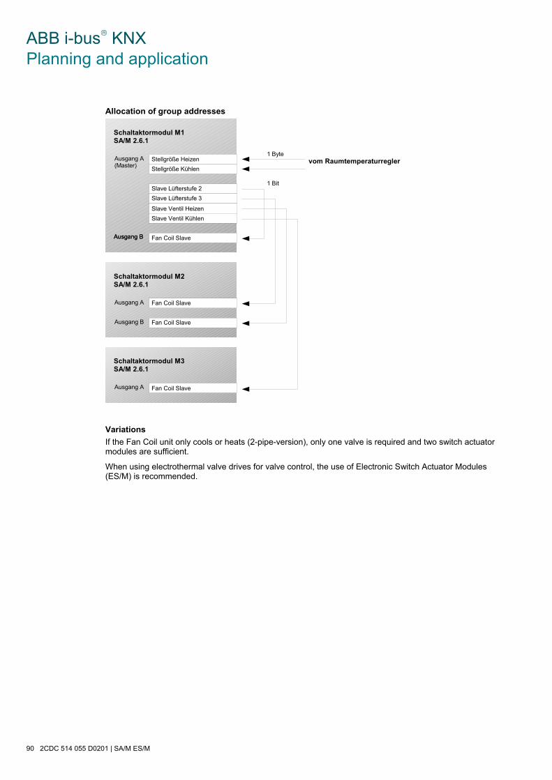
ABB i-bus® KNX Planning and application
90 2CDC 514 055 D0201 | SA/M ES/M
Allocation of group addresses
Schaltaktormodul M1SA/M 2.6.1
Stellgröße Heizen
Stellgröße Kühlen
Slave Lüfterstufe 2
Slave Lüfterstufe 3
Slave Ventil Heizen
vom Raumtemperaturregler1 Byte
1 Bit
Slave Ventil Kühlen
Fan Coil Slave
Ausgang A(Master)
Ausgang BAusgang B
Schaltaktormodul M2SA/M 2.6.1
Fan Coil Slave
Fan Coil Slave
Ausgang A
Ausgang B
Schaltaktormodul M3SA/M 2.6.1
Fan Coil SlaveAusgang A
Variations
If the Fan Coil unit only cools or heats (2-pipe-version), only one valve is required and two switch actuator modules are sufficient.
When using electrothermal valve drives for valve control, the use of Electronic Switch Actuator Modules (ES/M) is recommended.

ABB i-bus® KNX Planning and application
SA/M ES/M | 2CDC 514 055 D0201 91
4.5 Reaction on voltage failure and recovery
Reaction on bus voltage failure
The behaviour of the outputs at bus voltage failure can be parameterized. The function of the Room Controller is retained provided that the supply voltage (115 / 230 V AC or 12 V DC auxiliary voltage) is available.
If it has been set in the parameters, the Room Controller can thus continue to keep the functions in the room maintained even at bus voltage failure.
In the Heating actuator operating mode, any neutral position of the valve can be triggered. In the Fan coil control operating mode, the master and slave outputs are switched off (high-resistance). Fan speed 0 is thus triggered.
Example
Conventional push buttons are connected to a Room Controller via binary input modules. The Room Controller also regulates the lighting in the room. After bus voltage failure, the lighting can still be operated since the Room Controller is not supplied by the bus.
Reaction on bus voltage recovery
The behaviour of the outputs is programmable. In the master Fan coil control function, the outputs remain switched off until a new control value is received.
Reaction on supply voltage failure
The supply voltage has failed if there is a failure of both the 115/230 V AC supply and the 12 V DC auxiliary supply. The Room Controller has no function in this case.
For the Switch Actuator Module SA/M, the status of the relay outputs can be parameterized, so that a defined state can be established. The setting is carried out in the parameter Reaction on bus voltage failure.
In the Heating actuator operating mode, it can be set whether the valve should be fully open or closed during the supply voltage failure. In the Fan coil control operating mode, the master and slave outputs are opened. Fan speed 0 is thus triggered.
For the Electronic Switch Actuator Modules ES/M, the outputs always switch off during the supply voltage failure (high-resistance).
Note
The preset and scene values that have been changed by the user are lost on failure of the supply voltage. They are overwritten by the parameterized default values.
Reaction on supply voltage recovery
The behaviour of the outputs is identical to the behaviour on bus voltage recovery. It can be parameterized for each output (except for Fan Coil control).
4.6 Behaviour after programming
After programming, the device behaves in the same way as after bus voltage recovery (parameterizable).

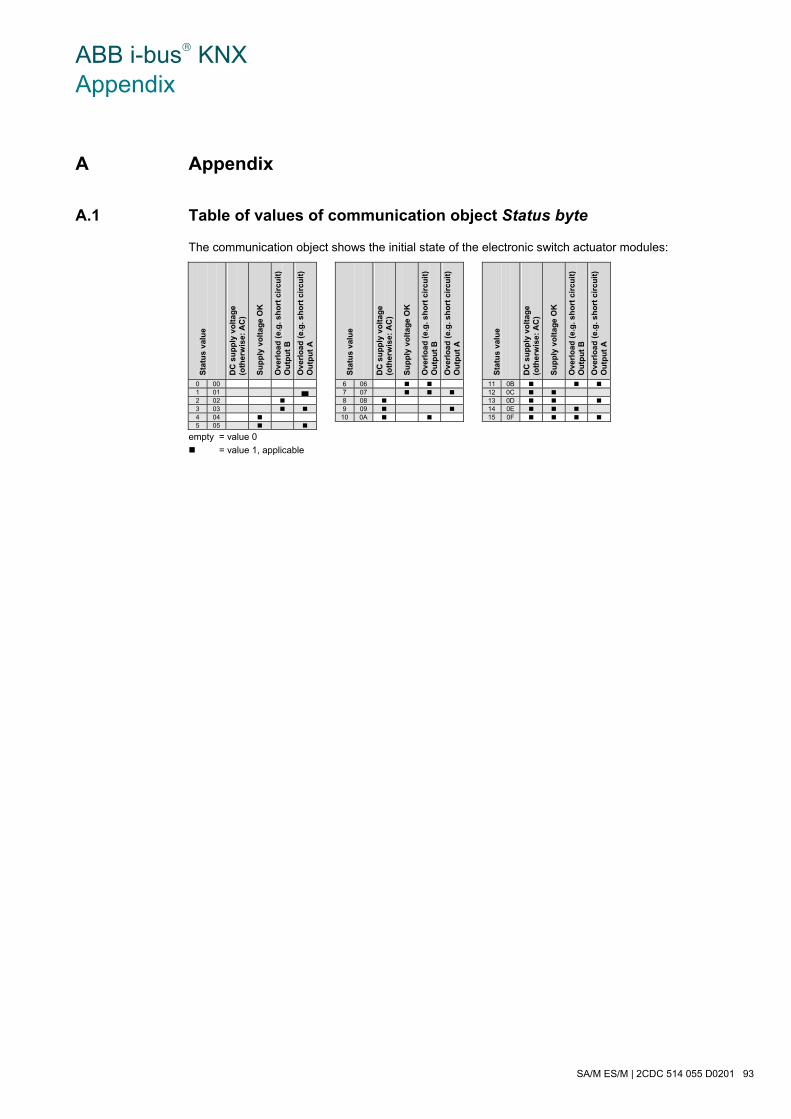
ABB i-bus® KNX Appendix
SA/M ES/M | 2CDC 514 055 D0201 93
A Appendix
A.1 Table of values of communication object Status byte
The communication object shows the initial state of the electronic switch actuator modules:
Sta
tus
val
ue
D
C s
up
ply
vo
ltag
e (o
ther
wis
e: A
C)
Su
pp
ly v
olt
age
OK
Ove
rlo
ad (
e.g
. sh
ort
cir
cuit
) O
utp
ut
B
Ove
rlo
ad (
e.g
. sh
ort
cir
cuit
) O
utp
ut
A
Sta
tus
val
ue
D
C s
up
ply
vo
ltag
e (o
ther
wis
e: A
C)
Su
pp
ly v
olt
age
OK
Ove
rlo
ad (
e.g
. sh
ort
cir
cuit
) O
utp
ut
B
Ove
rlo
ad (
e.g
. sh
ort
cir
cuit
) O
utp
ut
A
Sta
tus
val
ue
D
C s
up
ply
vo
ltag
e (o
ther
wis
e: A
C)
Su
pp
ly v
olt
age
OK
Ove
rlo
ad (
e.g
. sh
ort
cir
cuit
) O
utp
ut
B
Ove
rlo
ad (
e.g
. sh
ort
cir
cuit
) O
utp
ut
A
0 00 6 06 11 0B 1 01 7 07 12 0C 2 02 8 08 13 0D 3 03 9 09 14 0E 4 04 10 0A 15 0F 5 05
empty = value 0
= value 1, applicable
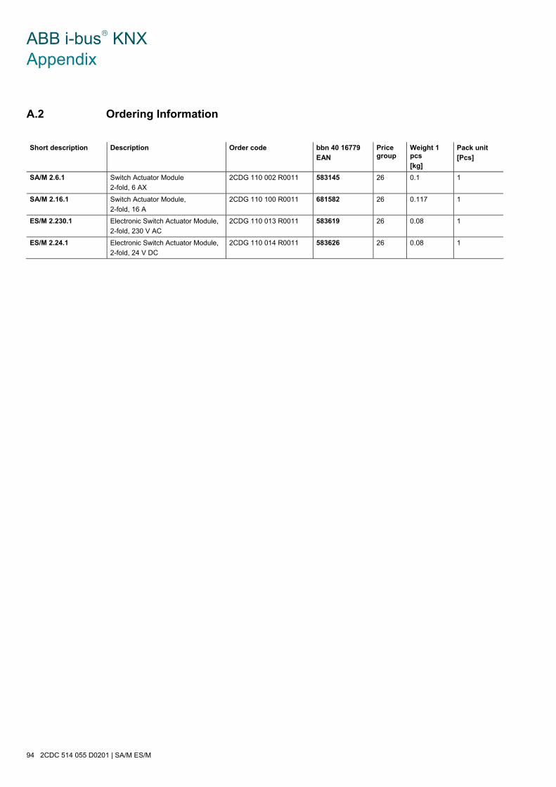
ABB i-bus® KNX Appendix
94 2CDC 514 055 D0201 | SA/M ES/M
A.2 Ordering Information
Short description Description Order code bbn 40 16779
EAN
Price group
Weight 1 pcs
[kg]
Pack unit
[Pcs]
SA/M 2.6.1 Switch Actuator Module
2-fold, 6 AX
2CDG 110 002 R0011 583145 26 0.1 1
SA/M 2.16.1 Switch Actuator Module,
2-fold, 16 A
2CDG 110 100 R0011 681582 26 0.117 1
ES/M 2.230.1 Electronic Switch Actuator Module,
2-fold, 230 V AC
2CDG 110 013 R0011 583619 26 0.08 1
ES/M 2.24.1 Electronic Switch Actuator Module,
2-fold, 24 V DC
2CDG 110 014 R0011 583626 26 0.08 1
ABB i-bus® KNX Appendix
SA/M ES/M | 2CDC 514 055 D0201 95
A.3 Notes

ABB i-bus® KNX Appendix
96 2CDC 514 055 D0201 | SA/M ES/M
A.4 Notes

Pub
licat
ion
Nu
mbe
r 2C
DC
51
4 05
5 D
020
1 (0
6.11
)
Note:We reserve the right to make technical changes to the products as well as amendments to the content of this document at any time without advance notice. The agreed properties are definitive for any orders placed. ABB AG shall not be liable for any consequences arising from errors or incomplete information in this document. We reserve the rights to this document and all the items and illustrations contained therein. Reproduction, transfer to third parties or processing of the content – including sections thereof – is not permitted without prior expressed written permission from ABB AG. Copyright© 2011 ABB All rights reserved
ABB STOTZ-KONTAKT GmbH Eppelheimer Straße 82 69123 Heidelberg, Germany Phone: +49 6221 701 607 Fax: +49 6221 701 724 e-mail: [email protected] Further information and local contacts: www.abb.com/knx
Contact