Swing arm optical CMM: self calib ration with dual probe ......4) Probe will be blind to the effects...
7
Swing arm optical CMM: self calibration with dual probe shear test Peng Su, Yuhao Wang, Chang Jin Oh, Robert E. Parks, James H. Burge College of Optical Sciences University of Arizona, Tucson, AZ 85721, U.S.A ABSTRACT Swing arm optical CMM (SOC), a profilometer with distance measuring interferometric probe for in situ measurement of the topography of aspheric has been used for measuring highly aspheric mirrors with a performance rivaling full aperture interferometric tests. Recently, we implemented a dual probe self calibration mode for the SOC. Data from the dual probes can be used to calibrate the swing-arm air bearing errors since both probes see the same bearing errors while measuring different portions of the test surface. Bearing errors are reconstructed from the shear signal with a modal estimation. Keywords: Swing arm Profilometer, SOC, Aspherics, optical testing, stitching, shear test 1. INTRODUCTION The Swing arm Optical Coordinate Measuring Machine (SOC) is an important metrology technique for highly aspheric surface testing [1, 2, 3, 4] because of its versatility and high accuracy. It is configurable for measuring concave, convex and plano surfaces, it can make in situ measurements, and it has high precision performance rivaling full aperture interferometric tests. Our previous work on SOC uses another independent test method to calibrate the SOC systematic errors [3]. Here we calibrate SOC with a dual probe lateral shear test to realize a self calibration. Shear test offers the opportunity of reconstruct the test surface without use of a external reference. There are tests to get shear data of the wavefront or surface irregularities such as shear interferometric test. And some other tests get the shear data of the wavefront slopes or surface slopes such as some curvature tests. The shear distance can be small which equals the spacing of the measurement points [5], or can have a relative large shear [6]. The shear data can in a one dimensional form [6] or two dimensional form [7]. Evaluating lateral shearing data has long been discussed in the literature, and several reconstruction methods have been proposed. One of the methods frequently applied is the modal method [5, 7]. It models the underlying wavefront or surface signal by a polynomial whose unknown coefficients are determined by least squares. The degree of the polynomials usually has to be chosen in advance. It works particularly well when the signals are smooth. The zonal method such as Southwell integration [8] retrievals the wavefront or surface data at discrete measurement points and solves a set of corresponding equations. It can also retrieval the data in a least square sense which has the advantage than a regular trapezoidal integration, however the lateral shear equaling to the spacing of measurement points is required. For the case of the shear is not small and without assuming a priori knowledge of the wavefront or surface, Elster [9] proposed a particular solution with so-called natural extension and discrete Fourier analysis. By choosing two different shears, the wavefront or surface can be reconstructed exactly at all measurement points. In this paper, we first reviewed the basic principle and performance of the SOC. Then the design and implementation of a dual probe self calibration is described. A modal estimate with Fourier series is chosen for the swing arm bearing errors retrieval based on our prior knowledge of the bearing errors. Optical Manufacturing and Testing IX, edited by James H. Burge, Oliver W. Fähnle, Ray Williamson, Proc. of SPIE Vol. 8126, 81260W · © 2011 SPIE · CCC code: 0277-786X/11/$18 · doi: 10.1117/12.894203 Proc. of SPIE Vol. 8126 81260W-1 Downloaded from SPIE Digital Library on 04 Dec 2011 to 150.135.113.157. Terms of Use: http://spiedl.org/terms
Transcript of Swing arm optical CMM: self calib ration with dual probe ......4) Probe will be blind to the effects...
Swing arm optical CMM: self calibration with dual probe shear test
Peng Su, Yuhao Wang, Chang Jin Oh, Robert E. Parks, James H. Burge College of Optical Sciences
University of Arizona, Tucson, AZ 85721, U.S.A
ABSTRACT
Swing arm optical CMM (SOC), a profilometer with distance measuring interferometric probe for in situ measurement of the topography of aspheric has been used for measuring highly aspheric mirrors with a performance rivaling full aperture interferometric tests. Recently, we implemented a dual probe self calibration mode for the SOC. Data from the dual probes can be used to calibrate the swing-arm air bearing errors since both probes see the same bearing errors while measuring different portions of the test surface. Bearing errors are reconstructed from the shear signal with a modal estimation.
Keywords: Swing arm Profilometer, SOC, Aspherics, optical testing, stitching, shear test
1. INTRODUCTION
The Swing arm Optical Coordinate Measuring Machine (SOC) is an important metrology technique for highly aspheric surface testing [1, 2, 3, 4] because of its versatility and high accuracy. It is configurable for measuring concave, convex and plano surfaces, it can make in situ measurements, and it has high precision performance rivaling full aperture interferometric tests.
Our previous work on SOC uses another independent test method to calibrate the SOC systematic errors [3]. Here we calibrate SOC with a dual probe lateral shear test to realize a self calibration. Shear test offers the opportunity of reconstruct the test surface without use of a external reference. There are tests to get shear data of the wavefront or surface irregularities such as shear interferometric test. And some other tests get the shear data of the wavefront slopes or surface slopes such as some curvature tests. The shear distance can be small which equals the spacing of the measurement points [5], or can have a relative large shear [6]. The shear data can in a one dimensional form [6] or two dimensional form [7].
Evaluating lateral shearing data has long been discussed in the literature, and several reconstruction methods have been proposed. One of the methods frequently applied is the modal method [5, 7]. It models the underlying wavefront or surface signal by a polynomial whose unknown coefficients are determined by least squares. The degree of the polynomials usually has to be chosen in advance. It works particularly well when the signals are smooth. The zonal method such as Southwell integration [8] retrievals the wavefront or surface data at discrete measurement points and solves a set of corresponding equations. It can also retrieval the data in a least square sense which has the advantage than a regular trapezoidal integration, however the lateral shear equaling to the spacing of measurement points is required. For the case of the shear is not small and without assuming a priori knowledge of the wavefront or surface, Elster [9] proposed a particular solution with so-called natural extension and discrete Fourier analysis. By choosing two different shears, the wavefront or surface can be reconstructed exactly at all measurement points.
In this paper, we first reviewed the basic principle and performance of the SOC. Then the design and implementation of a dual probe self calibration is described. A modal estimate with Fourier series is chosen for the swing arm bearing errors retrieval based on our prior knowledge of the bearing errors.
Optical Manufacturing and Testing IX, edited by James H. Burge, Oliver W. Fähnle, Ray Williamson,Proc. of SPIE Vol. 8126, 81260W · © 2011 SPIE · CCC code: 0277-786X/11/$18 · doi: 10.1117/12.894203
Proc. of SPIE Vol. 8126 81260W-1
Downloaded from SPIE Digital Library on 04 Dec 2011 to 150.135.113.157. Terms of Use: http://spiedl.org/terms
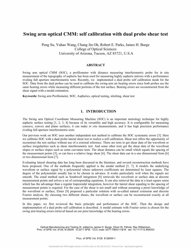
2. BASIC PRINCIPLE AND PERFORMANCE OF THE SOC
Figure 1. The basic geometry of the swing-arm profilometer
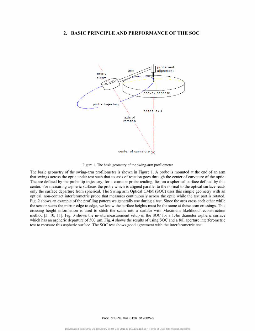
The basic geometry of the swing-arm profilometer is shown in Figure 1. A probe is mounted at the end of an arm that swings across the optic under test such that its axis of rotation goes through the center of curvature of the optic. The arc defined by the probe tip trajectory, for a constant probe reading, lies on a spherical surface defined by this center. For measuring aspheric surfaces the probe which is aligned parallel to the normal to the optical surface reads only the surface departure from spherical. The Swing arm Optical CMM (SOC) uses this simple geometry with an optical, non-contact interferometric probe that measures continuously across the optic while the test part is rotated. Fig. 2 shows an example of the profiling pattern we generally use during a test. Since the arcs cross each other while the sensor scans the mirror edge to edge, we know the surface heights must be the same at these scan crossings. This crossing height information is used to stitch the scans into a surface with Maximum likelihood reconstruction method [3, 10, 11]. Fig. 3 shows the in-situ measurement setup of the SOC for a 1.4m diameter aspheric surface which has an aspheric departure of 300 µm. Fig. 4 shows the results of using SOC and a full aperture interferometric test to measure this aspheric surface. The SOC test shows good agreement with the interferometric test.
Proc. of SPIE Vol. 8126 81260W-2
Downloaded from SPIE Digital Library on 04 Dec 2011 to 150.135.113.157. Terms of Use: http://spiedl.org/terms
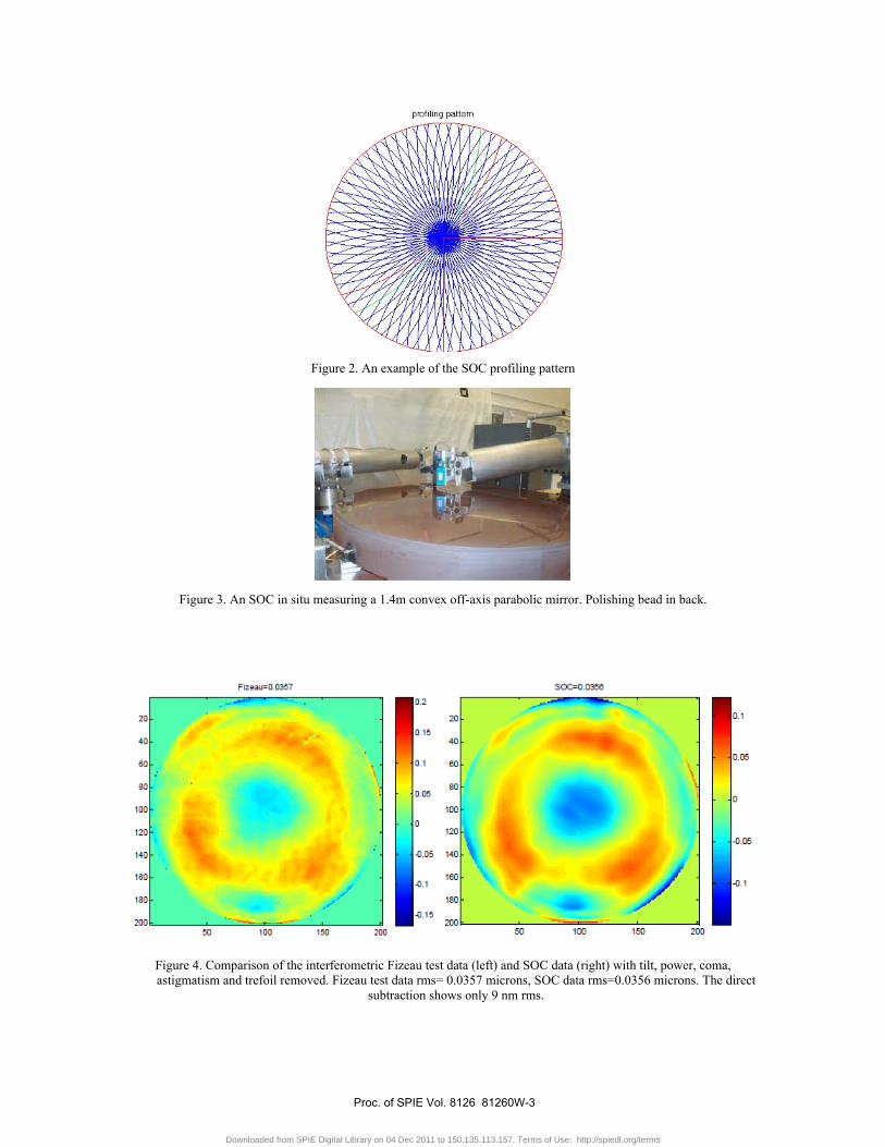
Figure 2. An example of the SOC profiling pattern
Figure 3. An SOC in situ measuring a 1.4m convex off-axis parabolic mirror. Polishing bead in back.
Figure 4. Comparison of the interferometric Fizeau test data (left) and SOC data (right) with tilt, power, coma, astigmatism and trefoil removed. Fizeau test data rms= 0.0357 microns, SOC data rms=0.0356 microns. The direct
subtraction shows only 9 nm rms.
Proc. of SPIE Vol. 8126 81260W-3
Downloaded from SPIE Digital Library on 04 Dec 2011 to 150.135.113.157. Terms of Use: http://spiedl.org/terms
3. SOC SYSTEMATIC ERROR CALIBRATION
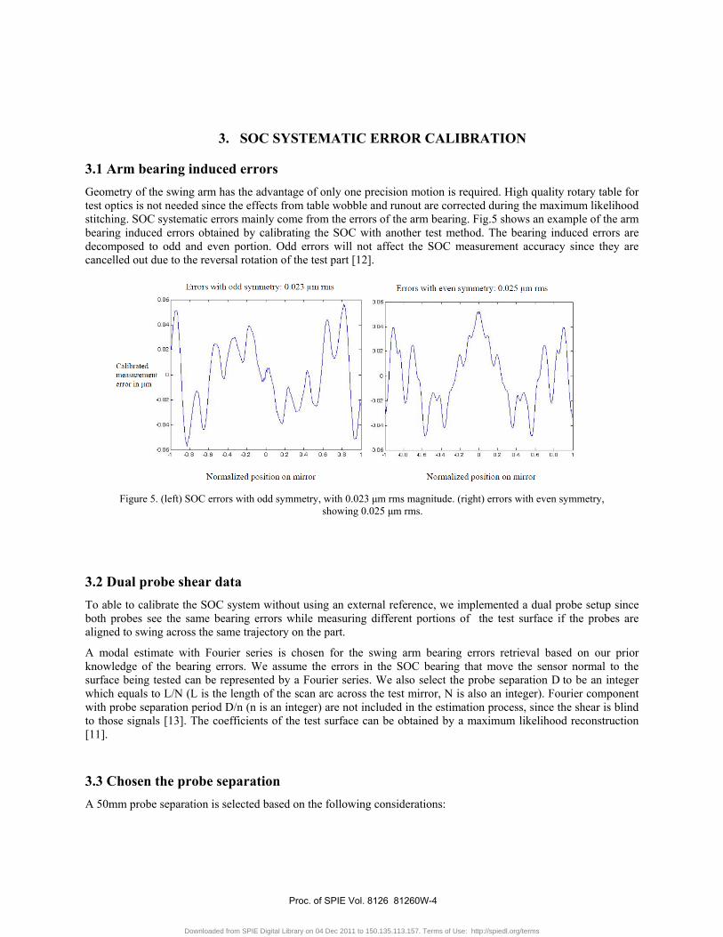
3.1 Arm bearing induced errors Geometry of the swing arm has the advantage of only one precision motion is required. High quality rotary table for test optics is not needed since the effects from table wobble and runout are corrected during the maximum likelihood stitching. SOC systematic errors mainly come from the errors of the arm bearing. Fig.5 shows an example of the arm bearing induced errors obtained by calibrating the SOC with another test method. The bearing induced errors are decomposed to odd and even portion. Odd errors will not affect the SOC measurement accuracy since they are cancelled out due to the reversal rotation of the test part [12].
Figure 5. (left) SOC errors with odd symmetry, with 0.023 μm rms magnitude. (right) errors with even symmetry,
showing 0.025 μm rms.
3.2 Dual probe shear data To able to calibrate the SOC system without using an external reference, we implemented a dual probe setup since both probes see the same bearing errors while measuring different portions of the test surface if the probes are aligned to swing across the same trajectory on the part.
A modal estimate with Fourier series is chosen for the swing arm bearing errors retrieval based on our prior knowledge of the bearing errors. We assume the errors in the SOC bearing that move the sensor normal to the surface being tested can be represented by a Fourier series. We also select the probe separation D to be an integer which equals to L/N (L is the length of the scan arc across the test mirror, N is also an integer). Fourier component with probe separation period D/n (n is an integer) are not included in the estimation process, since the shear is blind to those signals [13]. The coefficients of the test surface can be obtained by a maximum likelihood reconstruction [11].
3.3 Chosen the probe separation A 50mm probe separation is selected based on the following considerations:
Proc. of SPIE Vol. 8126 81260W-4
Downloaded from SPIE Digital Library on 04 Dec 2011 to 150.135.113.157. Terms of Use: http://spiedl.org/terms
1) Minimum separation is limited by the physical size or the package of the probes;
2) Too small separation is not preferred. Large difference signal is good for noise consideration;
3) Probe separation need avoid the periods of the bearing errors which we have the prior knowledge from
former data
4) Probe will be blind to the effects that have period of the separation.
3.4 Experiment setup
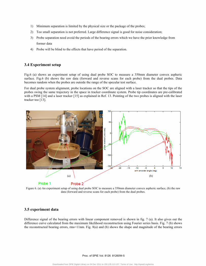
Fig.6 (a) shows an experiment setup of using dual probe SOC to measure a 350mm diameter convex aspheric surface. Fig.6 (b) shows the raw data (forward and reverse scans for each probe) from the dual probes. Data becomes random when the probes are outside the range of the specular test surface.
For dual probe system alignment, probe locations on the SOC are aligned with a laser tracker so that the tips of the probes swing the same trajectory in the space in tracker coordinate system. Probe tip coordinates are pre-calibrated with a PSM [14] and a laser tracker [15] as explained in Ref. 13. Pointing of the two probes is aligned with the laser tracker too [13].
Figure 6. (a) An experiment setup of using dual probe SOC to measure a 350mm diameter convex aspheric surface, (b) the raw data (forward and reverse scans for each probe) from the dual probes.
3.5 experiment data
Difference signal of the bearing errors with linear component removed is shown in fig. 7 (a). It also gives out the difference curve calculated from the maximum likelihood reconstruction using Fourier series basis. Fig. 7 (b) shows the reconstructed bearing errors, rms=11nm. Fig. 8(a) and (b) shows the shape and magnitude of the bearing errors
(a) (b)
Proc. of SPIE Vol. 8126 81260W-5
Downloaded from SPIE Digital Library on 04 Dec 2011 to 150.135.113.157. Terms of Use: http://spiedl.org/terms
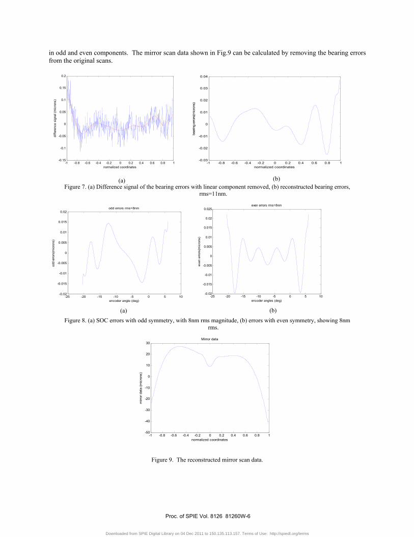
in odd and even components. The mirror scan data shown in Fig.9 can be calculated by removing the bearing errors from the original scans.
-1 -0.8 -0.6 -0.4 -0.2 0 0.2 0.4 0.6 0.8 1-0.15
-0.1
-0.05
0
0.05
0.1
0.15
0.2
normalized coordinates
diffe
renc
e si
gnal
(mic
rons
)
-1 -0.8 -0.6 -0.4 -0.2 0 0.2 0.4 0.6 0.8 1-0.03
-0.02
-0.01
0
0.01
0.02
0.03
0.04
normalized coordinates
bear
ing
erro
rs(m
icro
ns)
Figure 7. (a) Difference signal of the bearing errors with linear component removed, (b) reconstructed bearing errors, rms=11nm.
-25 -20 -15 -10 -5 0 5 10-0.02
-0.015
-0.01
-0.005
0
0.005
0.01
0.015
0.02odd errors rms=8nm
encoder angle (deg)
odd
erro
rs(m
icro
ns)
-25 -20 -15 -10 -5 0 5 10-0.02
-0.015
-0.01
-0.005
0
0.005
0.01
0.015
0.02
0.025even errors rms=8nm
encoder angles (deg)
even
erro
rs(m
icro
ns)
Figure 8. (a) SOC errors with odd symmetry, with 8nm rms magnitude, (b) errors with even symmetry, showing 8nm rms.
-1 -0.8 -0.6 -0.4 -0.2 0 0.2 0.4 0.6 0.8 1-50
-40
-30
-20
-10
0
10
20
30Mirror data
normalized coordinates
mirr
or d
ata
(mic
rons
)
Figure 9. The reconstructed mirror scan data.
(a) (b)
(a) (b)
Proc. of SPIE Vol. 8126 81260W-6
Downloaded from SPIE Digital Library on 04 Dec 2011 to 150.135.113.157. Terms of Use: http://spiedl.org/terms

4. DISCUSSION
Probe tip locations are currently aligned with a laser tracker. Calibration accuracy is related to the slope of the aspheric departure and the position accuracy of the probe as below
Error =aspheric slope x position error (10)
With a fixed probe separation D, the calibration is blind to effects that have period D/n (n=1, 2, 3…). This can be solved by calibrating the probe with multiple separations or using multiple probes. Algorithm from Ref [9] can be one of the solutions for the case with two shears. Our modal estimation with Maximum likelihood reconstruction can work with two shears and multiple shears.
Maximum likelihood reconstruction with Fourier series is used to estimate the bearing errors. Similar as the natural extension in Ref. 9, it assumes periodicity to take care of the properties of the difference data at region L-D (L is the diameter of the part; D is the separation of the probes). Errors from the reconstruction are limited by the noise in the test data. Difference signal from the bearing is used for reconstruction during the data reduction since it is smooth and can be well represented with finite number of polynomials.
REFERENCE
[1] Anderson, D. S., Parks, R. E. and Shao, T. “A versatile profilometer for aspheric optics”, in Proceedings of OF&T Workshop Technical Digest (Academic, Monterrey, CA 1990), Vol. 11, pp. 119–122.
[2] Anderson, D. S. and Burge, J. H. “Swing arm Profilometry of Aspherics”, Proc. SPIE 2356, 269–279 (1995). [3] Su, P., Oh, C. J., Parks, R. E. and Burge, J. H. “Swing arm optical CMM for aspherics”, Proc.SPIE 7426,
74260J–74260J −8 (2009). [4] Jing, H., King, C. and Walker, D., “Simulation and validation of a prototype swing arm profilometer for
measuring extremely large telescope mirror-segments”, Opt. Express 18, 2036-2048 (2010). [5] Freischlad, K. R. and Koliopoulos, C. L., “Modal estimation of a wavefront from difference measurements
using the discrete Fourier transform”, J. Opt. Soc. Am. A, Vol. 3, No. 11, 1852-1861, (1986) [6] Weingärtner, I., Schulz, M. and Elster, C. “Novel scanning technique for ultra-precise measurement of
topography,” SPIE, Vol. 3782, 306-317 (1999). [7] Harbers, G. , Kunst, P. J. and Leibbrandt, G. W. R. “Analysis of lateral shearing interferograms by use of
Zernike polynomials,” Appl. Opt. 35, 6162-6272 (1996). [8] Southwell, W. H. “Wavefront estimation from wavefront slope measurements,” J. Opt. Soc. Am. 70, 998-1006
(1980) [9] Elster, C. and Weingärtner, I. “Solution to the shearing problem,” App. Opt., Vol. 38, No. 23, 5024-5031
(1999) [10] Su, P., Burge, J.H., Sprowl, R. A. and Sasian, J.M. “Maximum Likelihood Estimation as a General Method of
Combining Sub-Aperture Data for Interferometric Testing,” International Optical Design Conference, Proc. of SPIE-OSA Vol. 6342 (2006)
[11] Su, P., Burge, J. H. and Parks, R. E. “Application of maximum likelihood reconstruction of sub-aperture data for measurement of large flat mirrors,’’ (On the issue cover) Applied Optics, Vol. 49 Issue 1, pp.21-31 (2010)
[12] Elster, C., Hocken, R., Estler, W., “Self-calibration: reversal, redundancy, error separation, and “ absolute testing,” CIRP Annals, 45/2, 567-584 (1996).
[13] Su, P., Wang, Y., Oh, C. J., Parks, R. E., Burge, H. J., “Swing arm optical CMM: modal estimation of systematic errors from dual probe shear measurements,” to be submitted to optical engineering.
[14] Parks, R. E. “Versatile Auto-stigmatic Microscope,” Proc. SPIE. 6290, 62890J (2006). [15] Burge, J. H., Su, P., Zhao, C., and Zobrist, T. “Use of a commercial laser tracker for optical alignment,” Proc.
SPIE. 6676, 66760E (2007).
Proc. of SPIE Vol. 8126 81260W-7
Downloaded from SPIE Digital Library on 04 Dec 2011 to 150.135.113.157. Terms of Use: http://spiedl.org/terms