SWELL AND SWELLING POTENTIAL PRESSURE …€¢ Constant volume swell test • Place an undisturbed...
21
SWELL AND SWELLING POTENTAL PRESSURE TESTS
Transcript of SWELL AND SWELLING POTENTIAL PRESSURE …€¢ Constant volume swell test • Place an undisturbed...
SWELL AND SWELLING POTENTAL PRESSURE TESTS
• When geotechnical engineers refer to expansive soils, we usually are thinking about clays , and the volume changes that occur as a result of changes in moisture content.
• Clays are fundamentally very different from gravels, sands, and silts. All the later consist of relatively inert bulky particles and their engineering properties depend primarily on the size, shape, and texture of these particles.
• In contrast, clays are made up of very small particles that are usually plate-shaped.
• The engineering properties of clays are strongly influenced by the very small size and large surface area of these particles and their inherent electrical charges.
• What cause a clay to Expand ?• Several different clay minerals occur in nature, the differences
being defined by their chemical makeup and structural configuration.
• Three of the most common clay minerals are
– Kaolinite
– Illite
– Montmorillonite
• The different chemical compositions and crystalline structures of these minerals give each a different susceptibility to swelling.
• Swelling occurs when water infiltrates between and within the clay particles, causing them to separate.
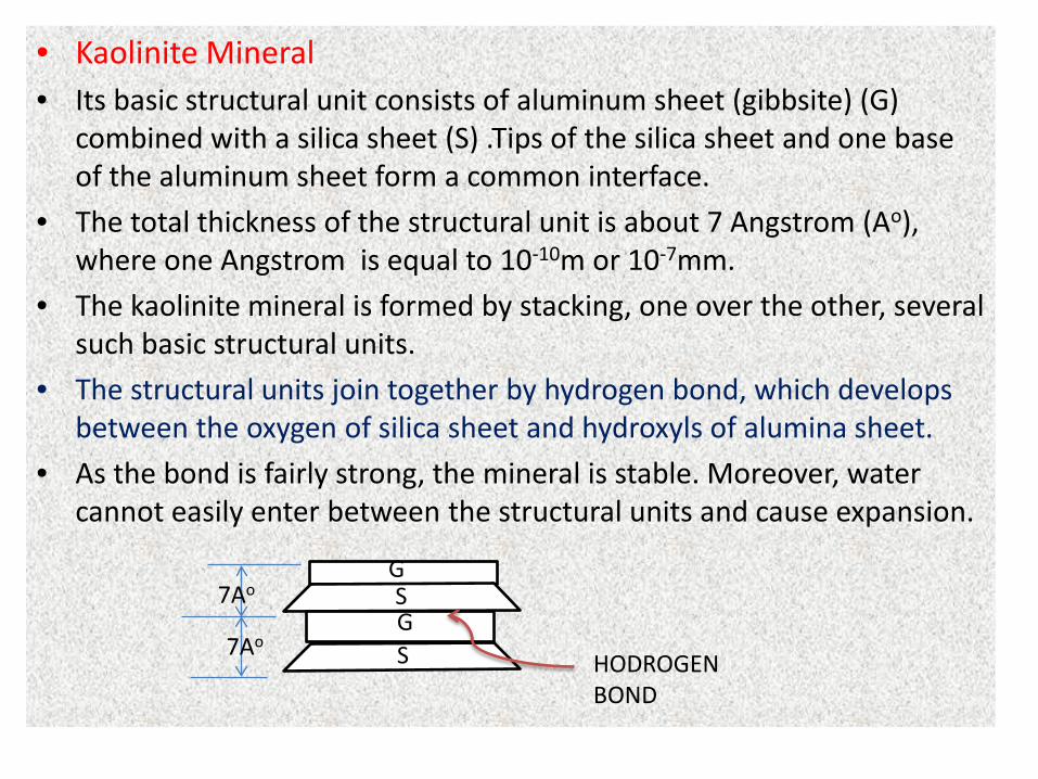
• Kaolinite Mineral• Its basic structural unit consists of aluminum sheet (gibbsite) (G)
combined with a silica sheet (S) .Tips of the silica sheet and one base of the aluminum sheet form a common interface.
• The total thickness of the structural unit is about 7 Angstrom (Ao), where one Angstrom is equal to 10-10m or 10-7mm.
• The kaolinite mineral is formed by stacking, one over the other, several such basic structural units.
• The structural units join together by hydrogen bond, which develops between the oxygen of silica sheet and hydroxyls of alumina sheet.
• As the bond is fairly strong, the mineral is stable. Moreover, water cannot easily enter between the structural units and cause expansion.
G
G S
S HODROGEN BOND
7Ao
7Ao
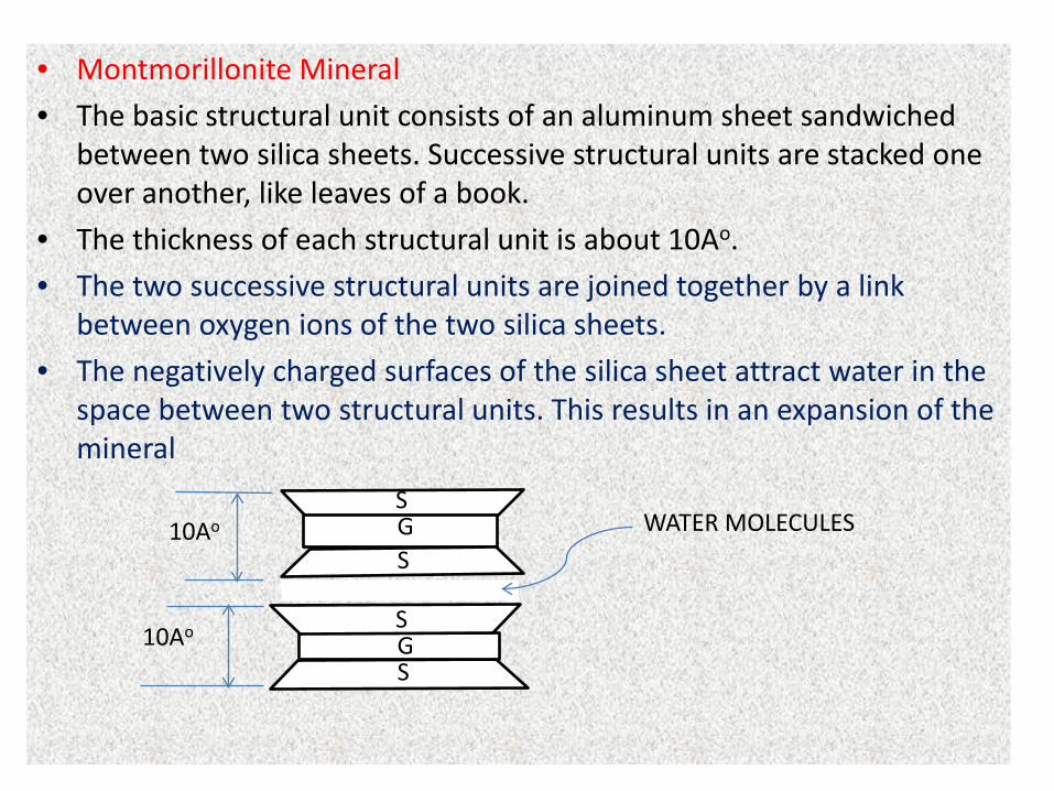
• Montmorillonite Mineral
• The basic structural unit consists of an aluminum sheet sandwiched between two silica sheets. Successive structural units are stacked one over another, like leaves of a book.
• The thickness of each structural unit is about 10Ao.
• The two successive structural units are joined together by a link between oxygen ions of the two silica sheets.
• The negatively charged surfaces of the silica sheet attract water in the space between two structural units. This results in an expansion of the mineral
G S
S 10Ao
10Ao
WATER MOLECULES
S G S
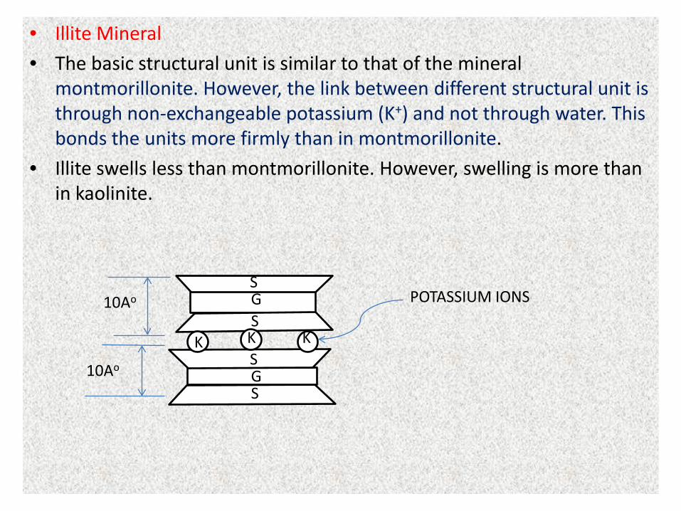
• Illite Mineral
• The basic structural unit is similar to that of the mineral montmorillonite. However, the link between different structural unit is through non-exchangeable potassium (K+) and not through water. This bonds the units more firmly than in montmorillonite.
• Illite swells less than montmorillonite. However, swelling is more than in kaolinite.
G S
S 10Ao
10Ao
POTASSIUM IONS
S G S
K K K
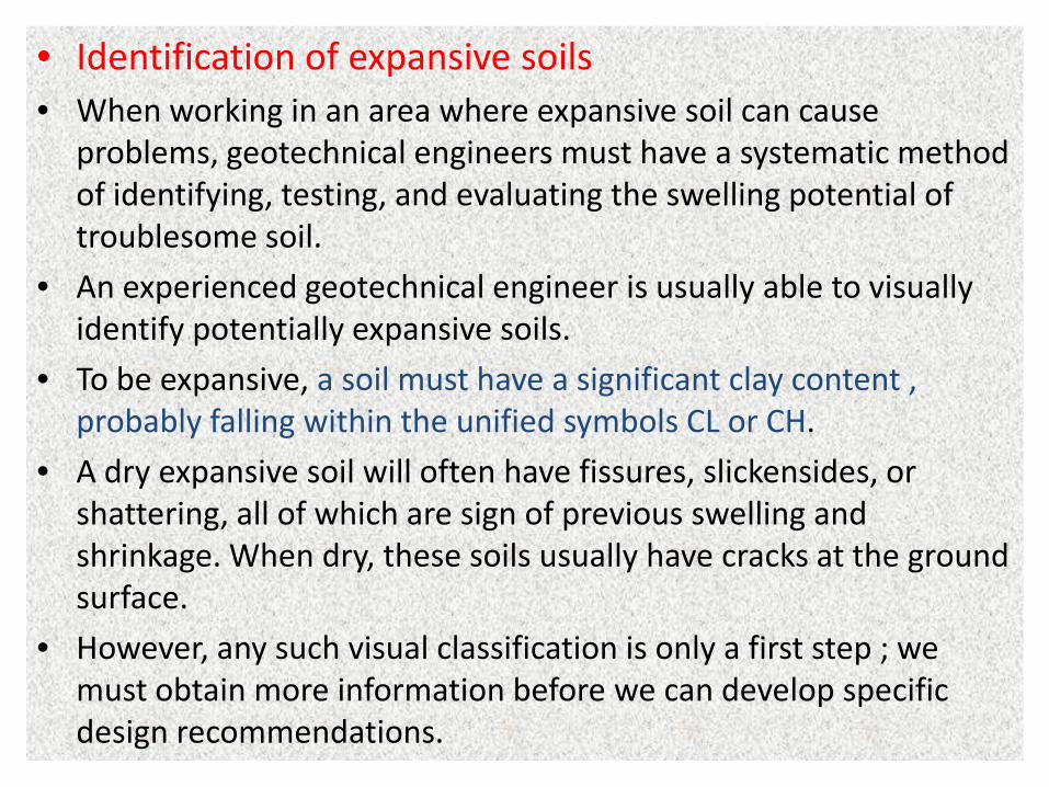
• Identification of expansive soils• When working in an area where expansive soil can cause
problems, geotechnical engineers must have a systematic method of identifying, testing, and evaluating the swelling potential of troublesome soil.
• An experienced geotechnical engineer is usually able to visually identify potentially expansive soils.
• To be expansive, a soil must have a significant clay content , probably falling within the unified symbols CL or CH.
• A dry expansive soil will often have fissures, slickensides, or shattering, all of which are sign of previous swelling and shrinkage. When dry, these soils usually have cracks at the ground surface.
• However, any such visual classification is only a first step ; we must obtain more information before we can develop specific design recommendations.
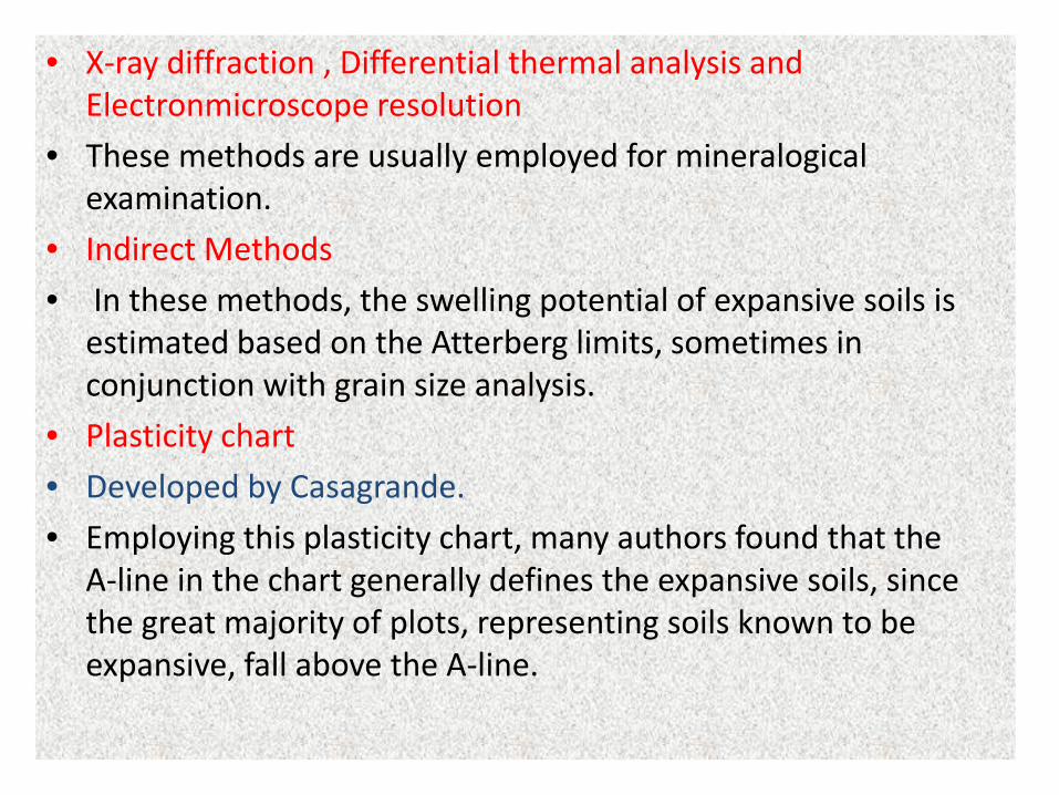
• X-ray diffraction , Differential thermal analysis and Electronmicroscope resolution
• These methods are usually employed for mineralogical examination.
• Indirect Methods
• In these methods, the swelling potential of expansive soils is estimated based on the Atterberg limits, sometimes in conjunction with grain size analysis.
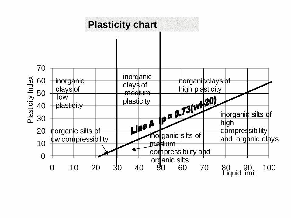
• Plasticity chart
• Developed by Casagrande.
• Employing this plasticity chart, many authors found that the A-line in the chart generally defines the expansive soils, since the great majority of plots, representing soils known to be expansive, fall above the A-line.
010203040506070
0 10 20 30 40 50 60 70 80 90 100
inorganicclays ofhigh plasticity
inorganic clays ofmedium plasticity
inorganic clays oflow plasticity
inorganic silts oflow compressibility inorganic silts of
medium compressibility and organic silts
inorganic silts ofhigh compressibility and organic clays
Liquid limit
Pla
stic
ity In
dex
Plasticity chart
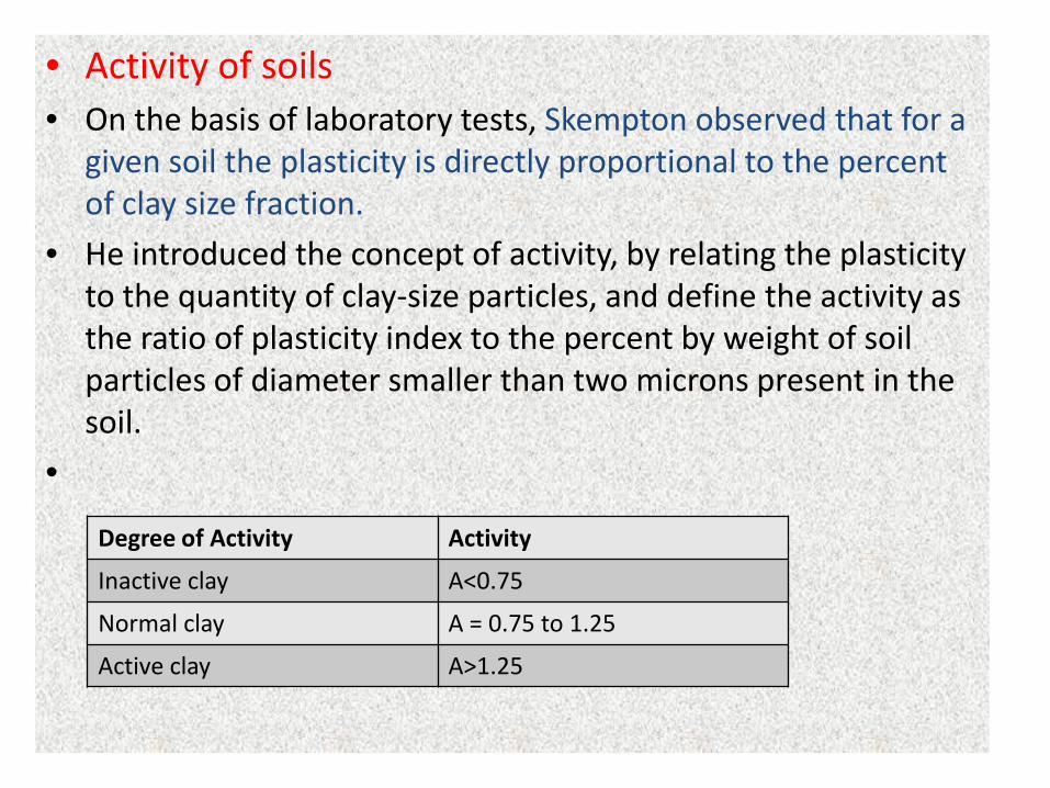
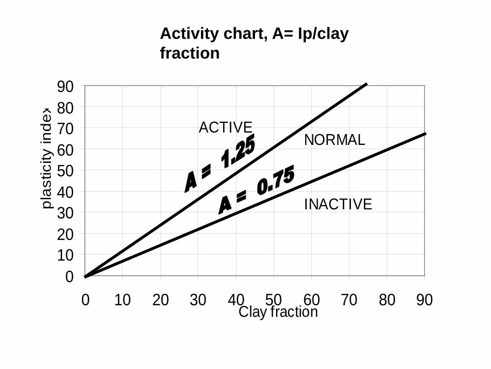
• Activity of soils• On the basis of laboratory tests, Skempton observed that for a
given soil the plasticity is directly proportional to the percent of clay size fraction.
• He introduced the concept of activity, by relating the plasticity to the quantity of clay-size particles, and define the activity as the ratio of plasticity index to the percent by weight of soil particles of diameter smaller than two microns present in the soil.
•
Degree of Activity Activity
Inactive clay A<0.75
Normal clay A = 0.75 to 1.25
Active clay A>1.25
0102030405060708090
0 10 20 30 40 50 60 70 80 90
INACTIVE
NORMALACTIVE
Clay fraction
plas
ticity
inde
xActivity chart, A= Ip/clay fraction
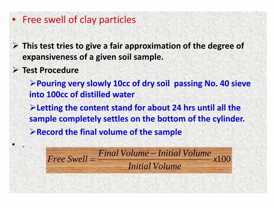
• Free swell of clay particles
This test tries to give a fair approximation of the degree of expansiveness of a given soil sample.
Test Procedure
Pouring very slowly 10cc of dry soil passing No. 40 sieve into 100cc of distilled water
Letting the content stand for about 24 hrs until all the sample completely settles on the bottom of the cylinder.
Record the final volume of the sample• .
100xVolumeInitial
VolumeInitialVolumeFinalSwellFree −=
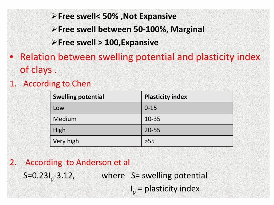
Free swell< 50% ,Not Expansive
Free swell between 50-100%, Marginal
Free swell > 100,Expansive
• Relation between swelling potential and plasticity index of clays .
1. According to Chen
2. According to Anderson et al
S=0.23Ip-3.12, where S= swelling potential
Ip = plasticity index
Swelling potential Plasticity index
Low 0-15
Medium 10-35
High 20-55
Very high >55
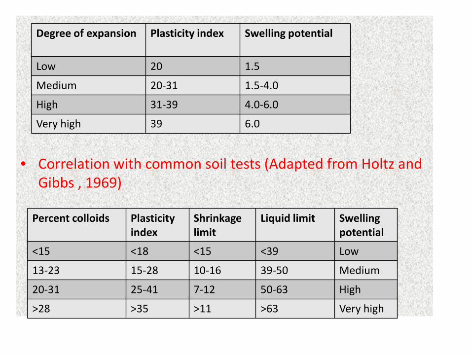
• Correlation with common soil tests (Adapted from Holtz and Gibbs , 1969)
Degree of expansion Plasticity index Swelling potential
Low 20 1.5
Medium 20-31 1.5-4.0
High 31-39 4.0-6.0
Very high 39 6.0
Percent colloids Plasticity index
Shrinkagelimit
Liquid limit Swellingpotential
<15 <18 <15 <39 Low
13-23 15-28 10-16 39-50 Medium
20-31 25-41 7-12 50-63 High
>28 >35 >11 >63 Very high
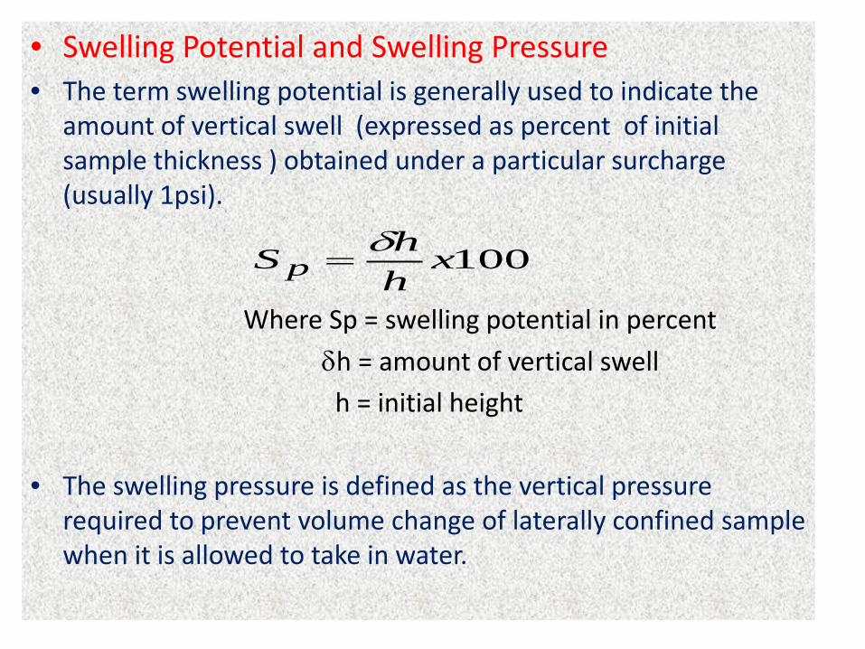
• Swelling Potential and Swelling Pressure• The term swelling potential is generally used to indicate the
amount of vertical swell (expressed as percent of initial sample thickness ) obtained under a particular surcharge (usually 1psi).
Where Sp = swelling potential in percent
δh = amount of vertical swellh = initial height
• The swelling pressure is defined as the vertical pressure required to prevent volume change of laterally confined sample when it is allowed to take in water.
100xhhS pδ
=
• The magnitude of swelling and/or swelling pressure is governed by the following factors
– Amount and type of clay in the soil
– Placement conditions which involve initial water content, initial density and confining pressure
– Time allowed for swelling
• In general
• For a given dry density percent expansion decreases with increase in moisture content
• For a given initial moisture content the swelling pressure increases with increase in dry density
• Percent expansion also increases with increase in dry density for a given initial moisture content
• Percent expansion decreases with increase in confining pressure for a given initial moisture content and density
• For expansion time is necessary. The same thing is true for swelling pressure.
• Laboratory Testing Methods for Determining Swelling Potential
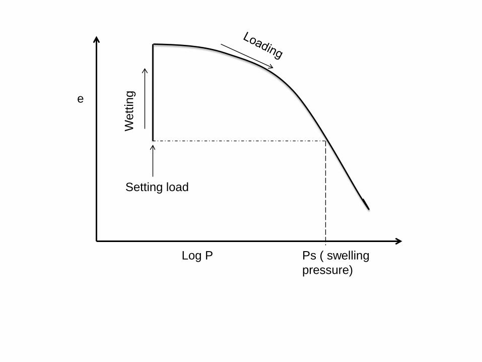
• Swell – Consolidation Method (Free swell method)• Place an undisturbed soil sample in a consolidometer and apply a
normal load equal to 1psi (7kN/m2)
• Inundate the sample and allow it to swell .
• After the swelling is complete, load the sample in increments until the soil returns to its original volume. The pressure that corresponds to the original volume is the swelling pressure.
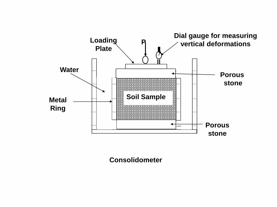
Porous stone
Metal Ring
Loading Plate
WaterPorous stone
Dial gauge for measuring vertical deformations
Soil Sample
P
Consolidometer
Ps ( swelling pressure)
Log P
e
Wet
ting
Setting load
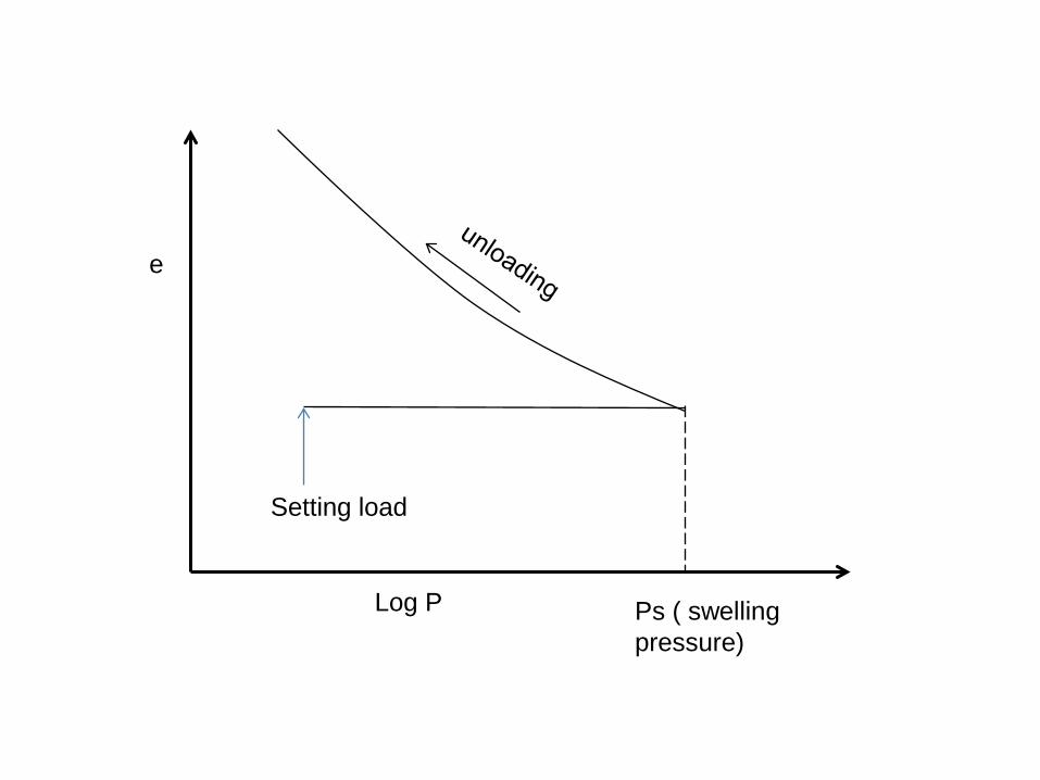
• Constant volume swell test• Place an undisturbed soil sample in a consolidometer and apply
a normal load equal to 1psi (7kN/m2) or in-situ overburden pressure
• Inundate the sample and begun increasing the normal load in increments as necessary to restrain any swelling. Continue until the swelling pressure is fully developed.
• Unload the soil in increments to obtain the swell curve.
Log P
e
Setting load
Ps ( swelling pressure)