SWEET MATTRESS DECK SLIDE - MORryde … Mattress Deck...SWEET MATTRESS DECK SLIDE ISTALLATI...
8
SWEET MATTRESS DECK SLIDE No more hassle of reaching in cramped spaces to make your bed. The Sweet Mattress Deck Slide moves the mattress out from the headboard so you can easily reach all sides of the mattress to make your bed. United States Patent 8,935,816
Transcript of SWEET MATTRESS DECK SLIDE - MORryde … Mattress Deck...SWEET MATTRESS DECK SLIDE ISTALLATI...

SWEET MATTRESS DECK SLIDE
No more hassle of reaching in cramped spaces to make your bed. The Sweet Mattress Deck Slide moves the mattress out from the headboard so you can easily reach all sides of the mattress to make your bed.
United States Patent 8,935,816

SWEET MATTRESS DECK SLIDE INSTALLATION INSTRUCTIONS
2
A BC
D
E F G HI
J K L M
N O
P
Q
RS
TU
QUALIFIERS
1. Original mattress deck can be no more than 48” from foot to hinge point. (Plywood for new mattress deck is only 48” wide)
2. Original mattress deck can be no less than 36” from foot to hinge point. (Due to length of retracted 24” actuator)
3. Must have at least 4” of open space under original mattress deck that extends from foot end to hinge point to accommodate actuator.
4. If there is less than 24” of open space at the foot end of the bed a limit switch (provided) must be used to limit travel to an acceptable range. Otherwise damage can occur to bed, mechanism, or other objects at the foot of the bed.
PARTS
Tools Required
• Electric drill• ½” drill bit• 3/8” drill bit• 3/16” drill bit• #2 Phillips bit• Circular Saw• 9/16” Wrenches• ¾” Wrenches• Wire stripper and crimper
Additional materials required (not included)
• One ½” sheet of BC plywood 4’x 8’ (more may be required for a king size bed)
• Electrical wire nuts or butt connectors, additional wiring to run from battery to bed
Item QTY DescriptionA 2 Actuator Braket
B 1 Limit Switch Stop
C 8 1” sq. Alum. Tube 47”
D 6 1” sq. Alum. Tube 24”
E 2 Reinforcement Block
F 2 Actuator Spacer Block
G 1 Actuator End, Rear
H 1 Actuator End, Front
I 1 Limit Switch and Bracket
J 2 3/8-16 x 2” Bolt
K 2 #10 x 1.00 Self Tap Screw
L 26 #8 x 0.75 Wood Screw
M 46 #8 x 1.25 Self Tap Screw
N 4 1/2-13 Nut
O 2 3/8-16 Nylock Nut
P 2 1/2-13 x 5” Threaded Rod
Q 1 Actuator
R 14 Female Quick Connect
S 2 Switch
T 1 15A Fuse Holder
U 1 15A Fuse

SWEET MATTRESS DECK SLIDE INSTALLATION INSTRUCTIONS
3
INSTALLATION
1. Remove original lower (foot end) bed deck by unscrewing it from the piano hinge. (save screws for re-installation)
2. Cut new plywood for the new mattress deck the same size as the original bed deck. (save original bed deck)
3. Attach ends (item G and H) to front and rear end of actuator with items J and O). See Figure 1.
For steps 4 - 9 reference Figure 2 above.
4. Assuming that there are no supports in the way, place the rear actuator block (item E) centered on the bottom side of the original bed deck approximately ½” from the hinge side and secure it with wood screws (item L)
5. Using the block (item E) as a guide drill a ½” hole through the original mattress deck. (If there is a support in the way place the block as close to the center as possible that will still allow the actuator to stay parallel to the mattress.)
6. With the actuator fully retracted and the actuator ends installed (item G & H) insert threaded rod (item P) into rear actuator end and through rear actuator block. Then be sure the actuator is straight and mark the location of the center of front actuator end.
7. Remove the actuator from the bed deck and cut a ¾” wide slot in the original mattress deck from the foot end to approximately ½” past the actuator end center marked in step 6. Be sure the slot is straight and in line with the actuator.
FIGURE 1
FIGURE 2
GRear
O
J
Q
O
J
H
Front
P
F
A
C
N
NJ
P
G
Room for
hinge
Hinge Side
Original Bed Deck
Travel Slot
2
2
1/23/4
SWEET MATTRESS DECK SLIDE INSTALLATION INSTRUCTIONS
4
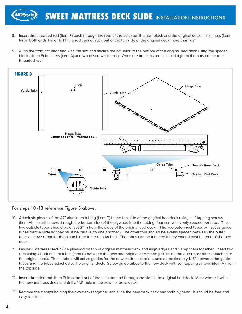
8. Insert the threaded rod (item P) back through the rear of the actuator, the rear block and the original deck, install nuts (item N) on both ends finger tight, the rod cannot stick out of the top side of the original deck more than 7/8”
9. Align the front actuator end with the slot and secure the actuator to the bottom of the original bed deck using the spacer blocks (item F) brackets (item A) and wood screws (item L). Once the brackets are installed tighten the nuts on the rear threaded rod.
For steps 10 -13 reference Figure 3 above.
10. Attach six pieces of the 47” aluminum tubing (item C) to the top side of the original bed deck using self-tapping screws (item M). Install screws through the bottom side of the plywood into the tubing, four screws evenly spaced per tube. The two outside tubes should be offset 2” in from the sides of the original bed deck. (The two outermost tubes will act as guide tubes for the slide so they must be parallel to one another.) The other four should be evenly spaced between the outer tubes. Leave room for the piano hinge to be re-attached. The tubes can be trimmed if they extend past the end of the bed deck.
11. Lay new Mattress Deck Slide plywood on top of original mattress deck and align edges and clamp them together. Insert two remaining 47” aluminum tubes (item C) between the new and original decks and just inside the outermost tubes attached to the original deck. These tubes will act as guides for the new mattress deck. Leave approximately 1/16” between the guide tubes and the tubes attached to the original deck. Screw guide tubes to the new deck with self-tapping screws (item M) from the top side.
12. Insert threaded rod (item P) into the front of the actuator and through the slot in the original bed deck. Mark where it will hit the new mattress deck and drill a 1/2” hole in the new mattress deck.
13. Remove the clamps holding the two decks together and slide the new deck back and forth by hand. It should be free and easy to slide.
FIGURE 3
G
G
N
NJ
New Mattress Deck
Hinge Side
Hinge Side
Guide Tube
Guide Tube
Guide TubeGuide Tube
2 2
1/16
Original Bed Deck

SWEET MATTRESS DECK SLIDE INSTALLATION INSTRUCTIONS
5
14. Remove the new deck. Insert the threaded rod through the front actuator block (item E) and then through the ½” hole in the new mattress deck to align the block with the new deck. The block should be on the same side as the two guide tubes. Screw the block to the new deck using wood screws (item L)
For steps 15 -19 reference Figure 4 above.
15. Run hot and ground wires from the battery to the bed deck area leave wires long.
16. Re-mount the original mattress deck at the piano hinge.
17. Measure the distance from the front end of the actuator to the bed frame. If the dimension is less than the actuator stroke then a notch will need cut into the bed frame to allow the actuator end to pass through for full extension.
18. Insert the threaded rod through the front actuator end and through the block on the new mattress deck, secure with a nut (item N) on both sides of the actuator end. Adjust the rod so the end is flush or just below the surface of the new mattress deck so it does not damage the mattress.
19. Measure the distance from the piano hinge to the head of the bed. If the dimension is less than 24” then cut the short aluminum tubes (item D) to fit. Drill 3/16” holes approximately 1” from the end through both walls of each tube. Then on one side only drill the 3/16” hole out to 3/8” as a clearance hole. Evenly space the tubes on the original bed deck above the piano hinge. Place the 3/16” hole side down and screw them down using wood screws (item L)
20. Cut remaining plywood to fit the area above the piano hinge and screw the plywood to the tubes using self-tapping screws (Item M). This will make the area above the piano hinge even with the new sliding mattress deck. Depending on the size of the remaining plywood it may need to be cut into multiple pieces to cover the head area. If the bed is king size then more than just the remaining plywood may be required to cover the head area.
FIGURE 4
Plywood not shown here for clarity
Optional notch if actuator
needs to travel through frame
SWEET MATTRESS DECK SLIDE INSTALLATION INSTRUCTIONS
6
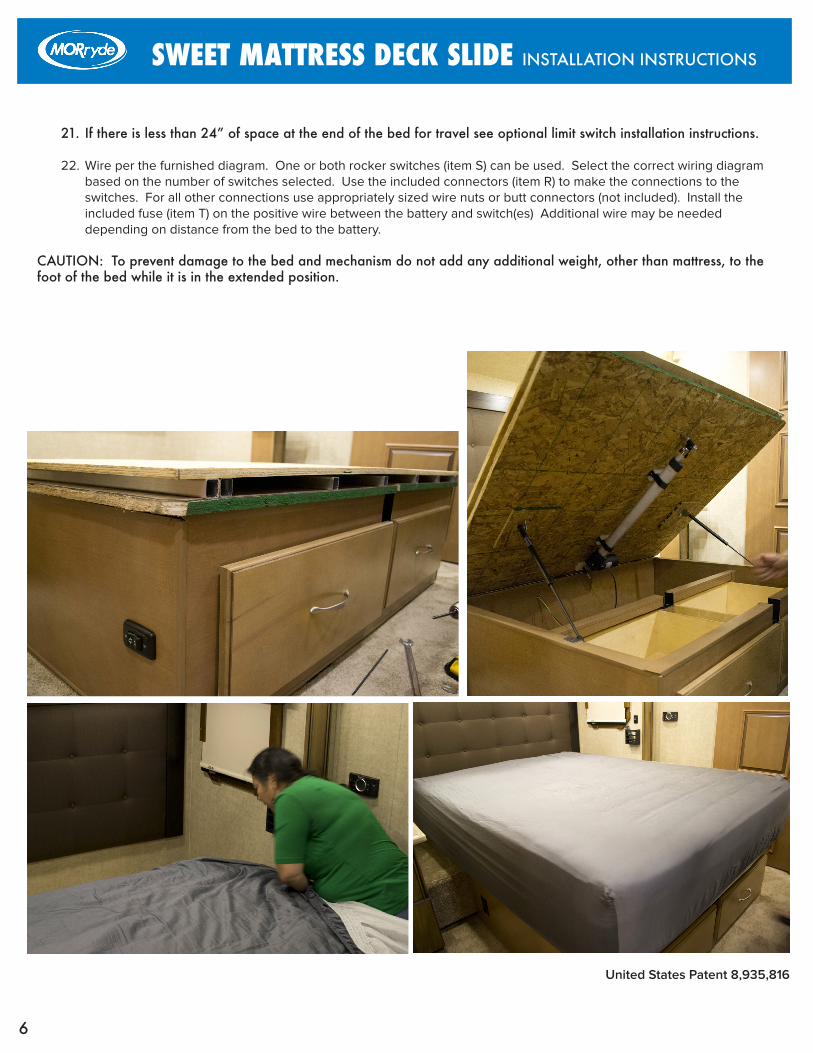
21. If there is less than 24” of space at the end of the bed for travel see optional limit switch installation instructions.
22. Wire per the furnished diagram. One or both rocker switches (item S) can be used. Select the correct wiring diagram based on the number of switches selected. Use the included connectors (item R) to make the connections to the switches. For all other connections use appropriately sized wire nuts or butt connectors (not included). Install the included fuse (item T) on the positive wire between the battery and switch(es) Additional wire may be needed depending on distance from the bed to the battery.
CAUTION: To prevent damage to the bed and mechanism do not add any additional weight, other than mattress, to the foot of the bed while it is in the extended position.
United States Patent 8,935,816
SWEET MATTRESS DECK SLIDE INSTALLATION INSTRUCTIONS
7
FIGURE 5
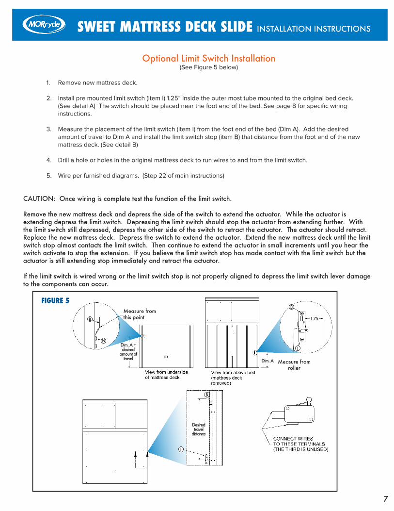
Optional Limit Switch Installation(See Figure 5 below)
1. Remove new mattress deck.
2. Install pre mounted limit switch (Item I) 1.25” inside the outer most tube mounted to the original bed deck. (See detail A) The switch should be placed near the foot end of the bed. See page 8 for specific wiring instructions.
3. Measure the placement of the limit switch (item I) from the foot end of the bed (Dim A). Add the desired amount of travel to Dim A and install the limit switch stop (item B) that distance from the foot end of the new mattress deck. (See detail B)
4. Drill a hole or holes in the original mattress deck to run wires to and from the limit switch.
5. Wire per furnished diagrams. (Step 22 of main instructions)
CAUTION: Once wiring is complete test the function of the limit switch.
Remove the new mattress deck and depress the side of the switch to extend the actuator. While the actuator is extending depress the limit switch. Depressing the limit switch should stop the actuator from extending further. With the limit switch still depressed, depress the other side of the switch to retract the actuator. The actuator should retract. Replace the new mattress deck. Depress the switch to extend the actuator. Extend the new mattress deck until the limit switch stop almost contacts the limit switch. Then continue to extend the actuator in small increments until you hear the switch activate to stop the extension. If you believe the limit switch stop has made contact with the limit switch but the actuator is still extending stop immediately and retract the actuator.
If the limit switch is wired wrong or the limit switch stop is not properly aligned to depress the limit switch lever damage to the components can occur.
B
B
O
N
I
I
Measure from this point
Measure from roller
1.75
Dim. A
Dim. A + desired
amount of travel
Desired travel
distance

SWEET MATTRESS DECK SLIDE INSTALLATION INSTRUCTIONS
8
One Switch Wiring Diagram
*Use wire provided for switchees and actuator, additional wire may be required to run from bed compartment to battery.
Two Switch Wiring Diagram
MORryde International, Inc. I 1966 Sterling Ave. Elkhart, Indiana 46516 I (574)293-1581 I www.MORryde.com