SW AP Composite Calculations B
26
The effective young's modulus of the facing is computed taking in to consideration the effect of the resin (polyester) also The facing is a laminate with the following orientation - 0/+45/-45/90… The effective youngs modulus is taken and used in the calculations below Input Units Converted Input Units Nomenclature Assumptions: Ef 13.86 GPa Ef 1.386E+10 Pa Effective Youngs Modulus of the facing sheet 1. The following formulas assume 2. Thin facing skin made of same tf 3.736 mm tf 0.003736 m Facing thickness 3. Uniform facing thickness => t1 = 4. Core relatively much less stiffer h 45 mm h 0.045 m Distance between facing skins = tf + tc 5. b <= (l/3) For Beam 6. For analytical calculation the be Gc 35 MPa Gc 35000000 Pa Shear modulus of the core Input sought from USE Kb 0.020833 Kb 0.0208333 Beam - bending deflection coefficient SSB Output given to USER Ks 0.25 Ks 0.25 Beam - shear deflection coefficient SSB P 36 KN P 36000 N Load acting on the Anchor Point L 2m L 2m Length of the beam b 0.6 m b 0.6 m Beam width M 18000 Nm Maximum bending moment (P*l)/4 F 18000 N Maximum shear force P/2 tc 41.264 mm tc 0.041264 m Core thickness Bending stiffness - D 31456.933 Nm2 Shear stiffness - S 945000 N Bending Deflection 0.190737 m 190.737 mm + Shear Deflection 0.0190476 m 19.04762 mm
-
Upload
spadu3003yahoocom -
Category
Documents
-
view
24 -
download
0
description
Composites calculation
Transcript of SW AP Composite Calculations B
The effective young's modulus of the facing is computed taking in to consideration the effect of the resin (polyester) also
The facing is a laminate with the following orientation - 0/+45/-45/90… The effective youngs modulus is taken and used in the calculations below
Input Units Converted Input Units Nomenclature Assumptions:
Ef 13.86 GPa Ef 1.386E+10 Pa Effective Youngs Modulus of the facing sheet 1. The following formulas assume symmetry about the neutral axis
2. Thin facing skin made of same material
tf 3.736 mm tf 0.003736 m Facing thickness 3. Uniform facing thickness => t1 = t2 = tf
4. Core relatively much less stiffer than skins
h 45 mm h 0.045 m Distance between facing skins = tf + tc 5. b <= (l/3) For Beam
6. For analytical calculation the beam is assumed to be simply supported on two sides
Gc 35 MPa Gc 35000000 Pa Shear modulus of the core
Input sought from USER
Kb 0.020833 Kb 0.0208333 Beam - bending deflection coefficient
SSB Output given to USER
Ks 0.25 Ks 0.25 Beam - shear deflection coefficient
SSB
P 36 KN P 36000 N Load acting on the Anchor Point
L 2 m L 2 m Length of the beam
b 0.6 m b 0.6 m Beam width
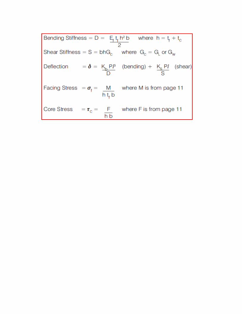
M 18000 Nm Maximum bending moment (P*l)/4
F 18000 N Maximum shear force P/2
tc 41.264 mm tc 0.041264 m Core thickness
Bending stiffness - D 31456.933 Nm2
Shear stiffness - S 945000 N
Bending Deflection 0.190737 m 190.737 mm
+
Shear Deflection 0.0190476 m 19.04762 mm
=
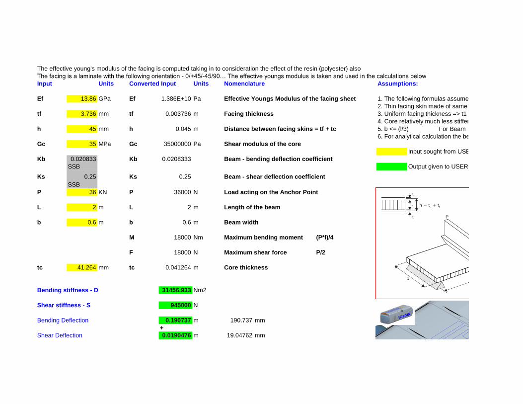
Net Deflection = Bending def + Shear def 0.2097846 m 209.7846 mm
Facing Stress 178443969 Pa 178.444 Mpa
Core Stress 666666.67 Pa 0.666667 Mpa
Check for design loads versus material's resistance
Fk Design Load
fk Resistance offered by material
γf Partial Safety factor for load 1
γm Partial safety factor for materials 2.4
γn Partial safety factor for consequence of failure1
1/(γm*γn) 0.4166667
Maximum Facing Stress of facing material 828 Mpa
Maximum core shear strength 1.6 Mpa
1. Check for facing Stress
Units Design Stress Permitted stress Compare & Decide
Mpa 178.444 345 Safe
2. Check for core shear stress

Mpa 0.666667 0.6666667 Safe

1. The following formulas assume symmetry about the neutral axis
2. Thin facing skin made of same material
3. Uniform facing thickness => t1 = t2 = tf
4. Core relatively much less stiffer than skins
6. For analytical calculation the beam is assumed to be simply supported on two sides
Input sought from USER Constant Value - Donot Change
Output given to USER
[90/-45/45/0/90/-45/45/0/Core/0/45/-45/90/0/45/-45/90]

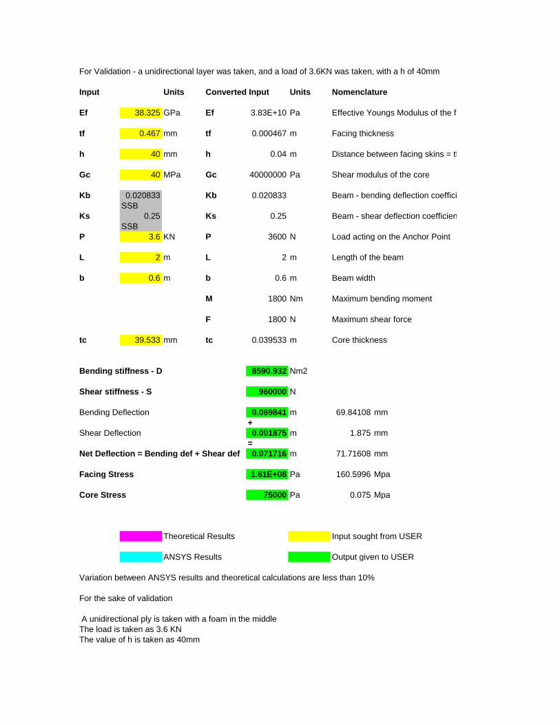
For Validation - a unidirectional layer was taken, and a load of 3.6KN was taken, with a h of 40mm
Input Units Converted Input Units Nomenclature
Ef 38.325 GPa Ef 3.83E+10 Pa Effective Youngs Modulus of the facing sheet
tf 0.467 mm tf 0.000467 m Facing thickness
h 40 mm h 0.04 m Distance between facing skins = tf + tc
Gc 40 MPa Gc 40000000 Pa Shear modulus of the core
Kb 0.020833 Kb 0.020833 Beam - bending deflection coefficient
SSB
Ks 0.25 Ks 0.25 Beam - shear deflection coefficient
SSB
P 3.6 KN P 3600 N Load acting on the Anchor Point
L 2 m L 2 m Length of the beam
b 0.6 m b 0.6 m Beam width
M 1800 Nm Maximum bending moment
F 1800 N Maximum shear force
tc 39.533 mm tc 0.039533 m Core thickness
Bending stiffness - D 8590.932 Nm2
Shear stiffness - S 960000 N
Bending Deflection 0.069841 m 69.84108 mm
+
Shear Deflection 0.001875 m 1.875 mm
=
Net Deflection = Bending def + Shear def 0.071716 m 71.71608 mm
Facing Stress 1.61E+08 Pa 160.5996 Mpa
Core Stress 75000 Pa 0.075 Mpa
Theoretical Results Input sought from USER
ANSYS Results Output given to USER
Variation between ANSYS results and theoretical calculations are less than 10%
For the sake of validation
A unidirectional ply is taken with a foam in the middle
The load is taken as 3.6 KN
The value of h is taken as 40mm


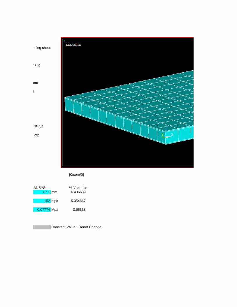
XZ SHEAR WITHOUT THE EDGE EFFECTS
Effective Youngs Modulus of the facing sheet
Distance between facing skins = tf + tc
Beam - bending deflection coefficient
Beam - shear deflection coefficient
(P*l)/4
P/2
[0/core/0]
ANSYS % Variation
67.1 mm 6.436609
152 mpa 5.354667
0.07774 Mpa -3.65333
Constant Value - Donot Change


XZ SHEAR WITHOUT THE EDGE EFFECTS


XZ SHEAR WITHOUT THE EDGE EFFECTS


XZ SHEAR WITHOUT THE EDGE EFFECTS


XZ SHEAR WITHOUT THE EDGE EFFECTS