SVM182 - Vantage 400 - Service Manual
166
SERVICE MANUAL VANTAGE ® 400 SVM182-A | Issue Date 11-Apr © Lincoln Global, Inc. All Rights Reserved. For use with machines having Code Numbers: 11186, 11462 Need Help? Call 1.888.935.3877 to talk to a Service Representative Hours of Operation: 8:00 AM to 6:00 PM (ET) Mon. thru Fri. After hours? Use “Ask the Experts” at lincolnelectric.com A Lincoln Service Representative will contact you no later than the following business day. For Service outside the USA: Email: [email protected] VANTAGE 400 LINCOLN ELECTRIC Return to Master TOC Return to Master TOC Return to Master TOC Return to Master TOC View Safety Info View Safety Info View Safety Info View Safety Info
-
Upload
martinjaitman -
Category
Documents
-
view
277 -
download
53
description
MANUAL
Transcript of SVM182 - Vantage 400 - Service Manual

SERVICE MANUAL
VANTAGE ® 400
SVM182-A | Issue D ate 11-Apr
© Lincoln Global, Inc. All Rights Reserved.
For use with machines having Code Numbers:
11186, 11462
Need Help? Call 1.888.935.3877 to talk to a Service Representative
Hours of Operation: 8:00 AM to 6:00 PM (ET) Mon. thru Fri.
After hours? Use “Ask the Experts” at lincolnelectric.comA Lincoln Service Representative will contact you no later than the following business day.
For Service outside the USA: Email: [email protected]
VANTAGE 400
LINCOLNELECTRIC
Ret
urn
to M
aste
r T
OC
Ret
urn
to M
aste
r T
OC
Ret
urn
to M
aste
r T
OC
Ret
urn
to M
aste
r T
OC
Vie
w S
afet
y In
foV
iew
Saf
ety
Info
Vie
w S
afet
y In
foV
iew
Saf
ety
Info
VANTAGE® 400
SAFETYi i
FOR ENGINEpowered equipment.
1.a. Turn the engine off before troubleshooting and maintenancework unless the maintenance work requires it to be running.
____________________________________________________1.b.Operate engines in open, well-ventilated
areas or vent the engine exhaust fumes outdoors.
____________________________________________________1.c. Do not add the fuel near an open flame weld-
ing arc or when the engine is running. Stopthe engine and allow it to cool before refuel-ing to prevent spilled fuel from vaporizing oncontact with hot engine parts and igniting. Donot spill fuel when filling tank. If fuel is spilled,wipe it up and do not start engine until fumeshave been eliminated.
____________________________________________________1.d. Keep all equipment safety guards, covers and devices in posi-
tion and in good repair.Keep hands, hair, clothing and toolsaway from V-belts, gears, fans and all other moving partswhen starting, operating or repairing equipment.
____________________________________________________
1.e. In some cases it may be necessary to remove safetyguards to perform required maintenance. Removeguards only when necessary and replace them when themaintenance requiring their removal is complete.Always use the greatest care when working near movingparts.
___________________________________________________
1.f. Do not put your hands near the engine fan.Do not attempt to override the governor oridler by pushing on the throttle control rodswhile the engine is running.
___________________________________________________1.g. To prevent accidentally starting gasoline engines while
turning the engine or welding generator during maintenancework, disconnect the spark plug wires, distributor cap ormagneto wire as appropriate.
ARC WELDING can be hazardous. PROTECT YOURSELF AND OTHERS FROM POSSIBLE SERIOUS INJURY OR DEATH.KEEP CHILDREN AWAY. PACEMAKER WEARERS SHOULD CONSULT WITH THEIR DOCTOR BEFORE OPERATING.
Read and understand the following safety highlights. For additional safety information, it is strongly recommended that youpurchase a copy of “Safety in Welding & Cutting - ANSI Standard Z49.1” from the American Welding Society, P.O. Box 351040,Miami, Florida 33135 or CSA Standard W117.2-1974. A Free copy of “Arc Welding Safety” booklet E205 is available from theLincoln Electric Company, 22801 St. Clair Avenue, Cleveland, Ohio 44117-1199.
BE SURE THAT ALL INSTALLATION, OPERATION, MAINTENANCE AND REPAIR PROCEDURES AREPERFORMED ONLY BY QUALIFIED INDIVIDUALS.
WARNING
ELECTRIC AND MAGNETIC FIELDSmay be dangerous
2.a. Electric current flowing through any conductor causes localized Electric and Magnetic Fields (EMF). Welding current creates EMF fields around welding cables and welding machines
2.b. EMF fields may interfere with some pacemakers, andwelders having a pacemaker should consult their physicianbefore welding.
2.c. Exposure to EMF fields in welding may have other healtheffects which are now not known.
2.d. All welders should use the following procedures in order tominimize exposure to EMF fields from the welding circuit:
2.d.1. Route the electrode and work cables together - Securethem with tape when possible.
2.d.2. Never coil the electrode lead around your body.
2.d.3. Do not place your body between the electrode andwork cables. If the electrode cable is on your right side, the work cable should also be on your right side.
2.d.4. Connect the work cable to the workpiece as close aspossible to the area being welded.
2.d.5. Do not work next to welding power source.
1.h. To avoid scalding, do not remove theradiator pressure cap when the engine ishot.
CALIFORNIA PROPOSITION 65 WARNINGS
Diesel engine exhaust and some of its constituentsare known to the State of California to cause can-cer, birth defects, and other reproductive harm.
The engine exhaust from this product containschemicals known to the State of California to causecancer, birth defects, or other reproductive harm.
The Above For Diesel Engines The Above For Gasoline Engines
Ret
urn
to M
aste
r T
OC
Ret
urn
to M
aste
r T
OC
Ret
urn
to M
aste
r T
OC
Ret
urn
to M
aste
r T
OC

SAFETYii ii
VANTAGE® 400
FUMES AND GASEScan be dangerous.5.a. Welding may produce fumes and gases
hazardous to health. Avoid breathing thesefumes and gases.When welding, keepyour head out of the fume. Use enoughventilation and/or exhaust at the arc to keep
fumes and gases away from the breathing zone. Whenwelding with electrodes which require specialventilation such as stainless or hard facing (seeinstructions on container or MSDS) or on lead orcadmium plated steel and other metals or coatingswhich produce highly toxic fumes, keep exposure aslow as possible and within applicable OSHA PEL andACGIH TLV limits using local exhaust or mechanical ven-tilation. In confined spaces or in some circumstances,outdoors, a respirator may be required. Additional pre-cautions are also required when welding on galvanizedsteel.
5. b. The operation of welding fume control equipment is affectedby various factors including proper use and positioning of theequipment, maintenance of the equipment and the specificwelding procedure and application involved. Worker expo-sure level should be checked upon installation and periodi-cally thereafter to be certain it is within applicable OSHA PELand ACGIH TLV limits.
5.c. Do not weld in locations near chlorinated hydrocarbon vaporscoming from degreasing, cleaning or spraying operations.The heat and rays of the arc can react with solvent vapors toform phosgene, a highly toxic gas, and other irritating prod-ucts.
5.d. Shielding gases used for arc welding can displace air andcause injury or death. Always use enough ventilation,especially in confined areas, to insure breathing air is safe.
5.e. Read and understand the manufacturer’s instructions for thisequipment and the consumables to be used, including thematerial safety data sheet (MSDS) and follow youremployer’s safety practices. MSDS forms are available fromyour welding distributor or from the manufacturer.
5.f. Also see item 1.b.
ARC RAYS can burn.4.a. Use a shield with the proper filter and cover
plates to protect your eyes from sparks andthe rays of the arc when welding or observingopen arc welding. Headshield and filter lensshould conform to ANSI Z87. I standards.
4.b. Use suitable clothing made from durable flame-resistantmaterial to protect your skin and that of your helpers fromthe arc rays.
4.c. Protect other nearby personnel with suitable, non-flammablescreening and/or warn them not to watch the arc nor exposethemselves to the arc rays or to hot spatter or metal.
ELECTRIC SHOCK can kill.3.a. The electrode and work (or ground) circuits
are electrically “hot” when the welder is on.Do not touch these “hot” parts with your bareskin or wet clothing. Wear dry, hole-freegloves to insulate hands.
3.b. Insulate yourself from work and ground using dry insulation.Make certain the insulation is large enough to cover your fullarea of physical contact with work and ground.
In addition to the normal safety precautions, if weldingmust be performed under electrically hazardousconditions (in damp locations or while wearing wetclothing; on metal structures such as floors, gratings orscaffolds; when in cramped positions such as sitting,kneeling or lying, if there is a high risk of unavoidable oraccidental contact with the workpiece or ground) usethe following equipment:
• Semiautomatic DC Constant Voltage (Wire) Welder.• DC Manual (Stick) Welder.• AC Welder with Reduced Voltage Control.
3.c. In semiautomatic or automatic wire welding, the electrode,electrode reel, welding head, nozzle or semiautomaticwelding gun are also electrically “hot”.
3.d. Always be sure the work cable makes a good electricalconnection with the metal being welded. The connectionshould be as close as possible to the area being welded.
3.e. Ground the work or metal to be welded to a good electrical(earth) ground.
3.f. Maintain the electrode holder, work clamp, welding cable andwelding machine in good, safe operating condition. Replacedamaged insulation.
3.g. Never dip the electrode in water for cooling.
3.h. Never simultaneously touch electrically “hot” parts ofelectrode holders connected to two welders because voltagebetween the two can be the total of the open circuit voltageof both welders.
3.i. When working above floor level, use a safety belt to protectyourself from a fall should you get a shock.
3.j. Also see Items 6.c. and 8.
Ret
urn
to M
aste
r T
OC
Ret
urn
to M
aste
r T
OC
Ret
urn
to M
aste
r T
OC
Ret
urn
to M
aste
r T
OC

VANTAGE® 400
SAFETYiii iii
FOR ELECTRICALLYpowered equipment.
8.a. Turn off input power using the disconnectswitch at the fuse box before working onthe equipment.
8.b. Install equipment in accordance with the U.S. NationalElectrical Code, all local codes and the manufacturer’srecommendations.
8.c. Ground the equipment in accordance with the U.S. NationalElectrical Code and the manufacturer’s recommendations.
CYLINDER may explodeif damaged.7.a. Use only compressed gas cylinders
containing the correct shielding gas for theprocess used and properly operatingregulators designed for the gas and
pressure used. All hoses, fittings, etc. should be suitable forthe application and maintained in good condition.
7.b. Always keep cylinders in an upright position securelychained to an undercarriage or fixed support.
7.c. Cylinders should be located:• Away from areas where they may be struck or subjected tophysical damage.
• A safe distance from arc welding or cutting operations andany other source of heat, sparks, or flame.
7.d. Never allow the electrode, electrode holder or any otherelectrically “hot” parts to touch a cylinder.
7.e. Keep your head and face away from the cylinder valve outletwhen opening the cylinder valve.
7.f. Valve protection caps should always be in place and handtight except when the cylinder is in use or connected foruse.
7.g. Read and follow the instructions on compressed gascylinders, associated equipment, and CGA publication P-l,“Precautions for Safe Handling of Compressed Gases inCylinders,” available from the Compressed Gas Association1235 Jefferson Davis Highway, Arlington, VA 22202.
WELDING and CUTTINGSPARKS can cause fire orexplosion.6.a. Remove fire hazards from the welding area.If
this is not possible, cover them to prevent the welding sparksfrom starting a fire. Remember that welding sparks and hotmaterials from welding can easily go through small cracksand openings to adjcent areas. Avoid welding near hydrauliclines. Have a fire extinguisher readily available.
6.b. Where compressed gases are to be used at the job site,special precautions should be used to prevent hazardoussituations. Refer to “Safety in Welding and Cutting” (ANSIStandard Z49.1) and the operating information for theequipment being used.
6.c. When not welding, make certain no part of the electrodecircuit is touching the work or ground. Accidental contact cancause overheating and create a fire hazard.
6.d. Do not heat, cut or weld tanks, drums or containers until theproper steps have been taken to insure that such procedureswill not cause flammable or toxic vapors from substancesinside. They can cause an explosion even though they havebeen “cleaned”. For information, purchase “RecommendedSafe Practices for the Preparation for Welding and Cutting ofContainers and Piping That Have Held HazardousSubstances”, AWS F4.1 from the American Welding Society(see address above).
6.e. Vent hollow castings or containers before heating, cutting orwelding. They may explode.
6.f. Sparks and spatter are thrown from the welding arc. Wear oilfree protective garments such as leather gloves, heavy shirt,cuffless trousers, high shoes and a cap over your hair. Wearear plugs when welding out of position or in confined places.Always wear safety glasses with side shields when in awelding area.
6.g. Connect the work cable to the work as close to the weldingarea as practical. Work cables connected to the buildingframework or other locations away from the welding areaincrease the possibility of the welding current passing throughlifting chains, crane cables or other alternate circuits. This cancreate fire hazards or overheat lifting chains or cables untilthey fail.
6.h. Also see item 1.c.
6.I. Read and follow NFPA 51B “ Standard for Fire PreventionDuring Welding, Cutting and Other Hot Work”, available fromNFPA, 1 Batterymarch Park,PO box 9101, Quincy, Ma022690-9101.
6.j. Do not use a welding power source for pipe thawing.
Refer to http://www.lincolnelectric.com/safety for additional safety information.
Ret
urn
to M
aste
r T
OC
Ret
urn
to M
aste
r T
OC
Ret
urn
to M
aste
r T
OC
Ret
urn
to M
aste
r T
OC

SAFETYiv iv
VANTAGE® 400
PRÉCAUTIONS DE SÛRETÉPour votre propre protection lire et observer toutes les instructionset les précautions de sûreté specifiques qui parraissent dans cemanuel aussi bien que les précautions de sûreté générales suiv-antes:
Sûreté Pour Soudage A L’Arc1. Protegez-vous contre la secousse électrique:
a. Les circuits à l’électrode et à la piéce sont sous tensionquand la machine à souder est en marche. Eviter toujourstout contact entre les parties sous tension et la peau nueou les vétements mouillés. Porter des gants secs et sanstrous pour isoler les mains.
b. Faire trés attention de bien s’isoler de la masse quand onsoude dans des endroits humides, ou sur un plancher met-allique ou des grilles metalliques, principalement dans les positions assis ou couché pour lesquelles une grandepartie du corps peut être en contact avec la masse.
c. Maintenir le porte-électrode, la pince de masse, le câble desoudage et la machine à souder en bon et sûr état defonc-tionnement.
d.Ne jamais plonger le porte-électrode dans l’eau pour lerefroidir.
e. Ne jamais toucher simultanément les parties sous tensiondes porte-électrodes connectés à deux machines à souderparce que la tension entre les deux pinces peut être le totalde la tension à vide des deux machines.
f. Si on utilise la machine à souder comme une source decourant pour soudage semi-automatique, ces precautionspour le porte-électrode s’applicuent aussi au pistolet desoudage.
2. Dans le cas de travail au dessus du niveau du sol, se protégercontre les chutes dans le cas ou on recoit un choc. Ne jamaisenrouler le câble-électrode autour de n’importe quelle partie ducorps.
3. Un coup d’arc peut être plus sévère qu’un coup de soliel, donc:
a. Utiliser un bon masque avec un verre filtrant approprié ainsiqu’un verre blanc afin de se protéger les yeux du rayon-nement de l’arc et des projections quand on soude ouquand on regarde l’arc.
b. Porter des vêtements convenables afin de protéger la peaude soudeur et des aides contre le rayonnement de l‘arc.
c. Protéger l’autre personnel travaillant à proximité ausoudage à l’aide d’écrans appropriés et non-inflammables.
4. Des gouttes de laitier en fusion sont émises de l’arc desoudage. Se protéger avec des vêtements de protection libresde l’huile, tels que les gants en cuir, chemise épaisse, pan-talons sans revers, et chaussures montantes.
5. Toujours porter des lunettes de sécurité dans la zone desoudage. Utiliser des lunettes avec écrans lateraux dans leszones où l’on pique le laitier.
6. Eloigner les matériaux inflammables ou les recouvrir afin deprévenir tout risque d’incendie dû aux étincelles.
7. Quand on ne soude pas, poser la pince à une endroit isolé dela masse. Un court-circuit accidental peut provoquer unéchauffement et un risque d’incendie.
8. S’assurer que la masse est connectée le plus prés possible dela zone de travail qu’il est pratique de le faire. Si on place lamasse sur la charpente de la construction ou d’autres endroitséloignés de la zone de travail, on augmente le risque de voirpasser le courant de soudage par les chaines de levage,câbles de grue, ou autres circuits. Cela peut provoquer desrisques d’incendie ou d’echauffement des chaines et descâbles jusqu’à ce qu’ils se rompent.
9. Assurer une ventilation suffisante dans la zone de soudage.Ceci est particuliérement important pour le soudage de tôlesgalvanisées plombées, ou cadmiées ou tout autre métal quiproduit des fumeés toxiques.
10. Ne pas souder en présence de vapeurs de chlore provenantd’opérations de dégraissage, nettoyage ou pistolage. Lachaleur ou les rayons de l’arc peuvent réagir avec les vapeursdu solvant pour produire du phosgéne (gas fortement toxique)ou autres produits irritants.
11. Pour obtenir de plus amples renseignements sur la sûreté, voirle code “Code for safety in welding and cutting” CSA StandardW 117.2-1974.
PRÉCAUTIONS DE SÛRETÉ POURLES MACHINES À SOUDER ÀTRANSFORMATEUR ET ÀREDRESSEUR
1. Relier à la terre le chassis du poste conformement au code del’électricité et aux recommendations du fabricant. Le dispositifde montage ou la piece à souder doit être branché à unebonne mise à la terre.
2. Autant que possible, I’installation et l’entretien du poste seronteffectués par un électricien qualifié.
3. Avant de faires des travaux à l’interieur de poste, la debranch-er à l’interrupteur à la boite de fusibles.
4. Garder tous les couvercles et dispositifs de sûreté à leur place.
Ret
urn
to M
aste
r T
OC
Ret
urn
to M
aste
r T
OC
Ret
urn
to M
aste
r T
OC
Ret
urn
to M
aste
r T
OC

I I- MASTER TABLE OF CONTENTS FOR ALL SECTIONS -
VANTAGE® 400
Page
Safety . . . . . . . . . . . . . . . . . . . . . . . . . . . . . . . . . . . . . . . . . . . . . . . . . . . . . . . . . . . . . . . . . . . . . . . . . . .i-iv
Installation . . . . . . . . . . . . . . . . . . . . . . . . . . . . . . . . . . . . . . . . . . . . . . . . . . . . . . . . . . . . . . . . . .Section A
Operation . . . . . . . . . . . . . . . . . . . . . . . . . . . . . . . . . . . . . . . . . . . . . . . . . . . . . . . . . . . . . . . . . .Section B
Accessories . . . . . . . . . . . . . . . . . . . . . . . . . . . . . . . . . . . . . . . . . . . . . . . . . . . . . . . . . . . . . . . .Section C
Maintenance . . . . . . . . . . . . . . . . . . . . . . . . . . . . . . . . . . . . . . . . . . . . . . . . . . . . . . . . . . . . . . . .Section D
Theory of Operation . . . . . . . . . . . . . . . . . . . . . . . . . . . . . . . . . . . . . . . . . . . . . . . . . . . . . . . . . .Section E
Troubleshooting and Repair . . . . . . . . . . . . . . . . . . . . . . . . . . . . . . . . . . . . . . . . . . . . . . . . . . .Section F
Electrical Diagrams . . . . . . . . . . . . . . . . . . . . . . . . . . . . . . . . . . . . . . . . . . . . . . . . . . . . . . . . . .Section G
Parts Manual . . . . . . . . . . . . . . . . . . . . . . . . . . . . . . . . . . . . . . . . . . . . . . . . . . . . . . . . . . . . . . . . . . .P-528

TABLE OF CONTENTS - INSTALLATION SECTIONA-1 A-1
VANTAGE® 400
Installation . . . . . . . . . . . . . . . . . . . . . . . . . . . . . . . . . . . . . . . . . . . . . . . . . . . . . . . . . . . . . . . . . . . . . . . . . . . . .A-1
Technical Specifications . . . . . . . . . . . . . . . . . . . . . . . . . . . . . . . . . . . . . . . . . . . . . . . . . . . . . . . . . . . . . . . .A-2
Safety Precautions . . . . . . . . . . . . . . . . . . . . . . . . . . . . . . . . . . . . . . . . . . . . . . . . . . . . . . . . . . . . . . . . .A-3
VRD (Voltage Reduction Device) . . . . . . . . . . . . . . . . . . . . . . . . . . . . . . . . . . . . . . . . . . . . . . . . . . . . .A-3
Location and Ventilation . . . . . . . . . . . . . . . . . . . . . . . . . . . . . . . . . . . . . . . . . . . . . . . . . . . . . . . . . . . . .A-3
Stacking . . . . . . . . . . . . . . . . . . . . . . . . . . . . . . . . . . . . . . . . . . . . . . . . . . . . . . . . . . . . . . . . . . . . . . . . .A-3
Angle of Operation . . . . . . . . . . . . . . . . . . . . . . . . . . . . . . . . . . . . . . . . . . . . . . . . . . . . . . . . . . . . . . . . .A-3
Lifting . . . . . . . . . . . . . . . . . . . . . . . . . . . . . . . . . . . . . . . . . . . . . . . . . . . . . . . . . . . . . . . . . . . . . . . . . . .A-3
High Altitude Operation . . . . . . . . . . . . . . . . . . . . . . . . . . . . . . . . . . . . . . . . . . . . . . . . . . . . . . . . . . . . .A-4
High Temperature Operation . . . . . . . . . . . . . . . . . . . . . . . . . . . . . . . . . . . . . . . . . . . . . . . . . . . . . . . . .A-4
Cold Weather Operation . . . . . . . . . . . . . . . . . . . . . . . . . . . . . . . . . . . . . . . . . . . . . . . . . . . . . . . . . . . .A-4
Towing . . . . . . . . . . . . . . . . . . . . . . . . . . . . . . . . . . . . . . . . . . . . . . . . . . . . . . . . . . . . . . . . . . . . . . . . . .A-4
Vehicle Mounting . . . . . . . . . . . . . . . . . . . . . . . . . . . . . . . . . . . . . . . . . . . . . . . . . . . . . . . . . . . . . . . . . .A-4
Pre-Operation Engine Service . . . . . . . . . . . . . . . . . . . . . . . . . . . . . . . . . . . . . . . . . . . . . . . . . . . . . . . . . . .A-4
Oil . . . . . . . . . . . . . . . . . . . . . . . . . . . . . . . . . . . . . . . . . . . . . . . . . . . . . . . . . . . . . . . . . . . . . . . . . . . . . .A-5
Fuel . . . . . . . . . . . . . . . . . . . . . . . . . . . . . . . . . . . . . . . . . . . . . . . . . . . . . . . . . . . . . . . . . . . . . . . . . . . .A-5
Engine Coolant . . . . . . . . . . . . . . . . . . . . . . . . . . . . . . . . . . . . . . . . . . . . . . . . . . . . . . . . . . . . . . . . . . .A-5
Battery Connections . . . . . . . . . . . . . . . . . . . . . . . . . . . . . . . . . . . . . . . . . . . . . . . . . . . . . . . . . . . . . . .A-5
Muffler Outlet Pipe . . . . . . . . . . . . . . . . . . . . . . . . . . . . . . . . . . . . . . . . . . . . . . . . . . . . . . . . . . . . . . . . .A-5
Spark Arrester . . . . . . . . . . . . . . . . . . . . . . . . . . . . . . . . . . . . . . . . . . . . . . . . . . . . . . . . . . . . . . . . . . . .A-5
Remote Control . . . . . . . . . . . . . . . . . . . . . . . . . . . . . . . . . . . . . . . . . . . . . . . . . . . . . . . . . . . . . . . . . . .A-5
Electrical Connections . . . . . . . . . . . . . . . . . . . . . . . . . . . . . . . . . . . . . . . . . . . . . . . . . . . . . . . . . . . . . . . . .A-6
Machine Grounding . . . . . . . . . . . . . . . . . . . . . . . . . . . . . . . . . . . . . . . . . . . . . . . . . . . . . . . . . . . . . . . .A-6
Welding Terminals . . . . . . . . . . . . . . . . . . . . . . . . . . . . . . . . . . . . . . . . . . . . . . . . . . . . . . . . . . . . . . . . .A-6
Welding Output Cables . . . . . . . . . . . . . . . . . . . . . . . . . . . . . . . . . . . . . . . . . . . . . . . . . . . . . . . . . . . . .A-6
Cable Installation . . . . . . . . . . . . . . . . . . . . . . . . . . . . . . . . . . . . . . . . . . . . . . . . . . . . . . . . . . . . . . . . . .A-6
Auxiliary Power Receptacles and Plugs . . . . . . . . . . . . . . . . . . . . . . . . . . . . . . . . . . . . . . . . . . . . . . . . . . . . . . .A-7
Standby Power Connections . . . . . . . . . . . . . . . . . . . . . . . . . . . . . . . . . . . . . . . . . . . . . . . . . . . . . . . . . . . . . . .A-7
Premises Wiring . . . . . . . . . . . . . . . . . . . . . . . . . . . . . . . . . . . . . . . . . . . . . . . . . . . . . . . . . . . . . . . . . . . . . . . . .A-8
Connection of Lincoln Electric Wire Feeders . . . . . . . . . . . . . . . . . . . . . . . . . . . . . . . . . . . . . . . . . . . . . .A-9, A-10
Ret
urn
to M
aste
r TO
CR
etur
n to
Mas
ter
TOC
Ret
urn
to M
aste
r TO
CR
etur
n to
Mas
ter
TOC
INSTALLATIONA-2 A-2
VANTAGE® 400
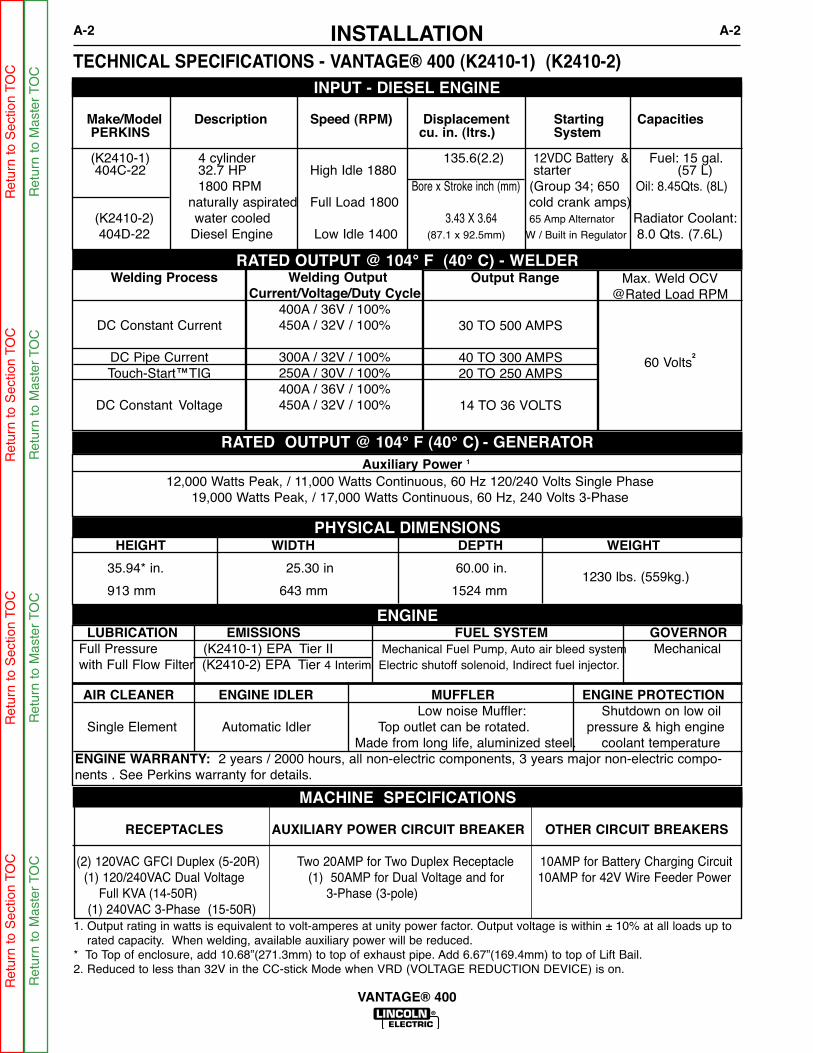
1. Output rating in watts is equivalent to volt-amperes at unity power factor. Output voltage is within ± 10% at all loads up torated capacity. When welding, available auxiliary power will be reduced.
* To Top of enclosure, add 10.68”(271.3mm) to top of exhaust pipe. Add 6.67”(169.4mm) to top of Lift Bail.2. Reduced to less than 32V in the CC-stick Mode when VRD (VOLTAGE REDUCTION DEVICE) is on.
TECHNICAL SPECIFICATIONS - VANTAGE® 400 (K2410-1) (K2410-2)
RATED OUTPUT @ 104° F (40° C) - WELDER
HEIGHT WIDTH DEPTH WEIGHT
35.94* in. 25.30 in 60.00 in.
913 mm 643 mm 1524 mm
LUBRICATION EMISSIONS FUEL SYSTEM GOVERNORFull Pressure (K2410-1) EPA Tier II Mechanical Fuel Pump, Auto air bleed system Mechanicalwith Full Flow Filter (K2410-2) EPA Tier 4 Interim Electric shutoff solenoid, Indirect fuel injector.
AIR CLEANER ENGINE IDLER MUFFLER ENGINE PROTECTIONLow noise Muffler: Shutdown on low oil
Single Element Automatic Idler Top outlet can be rotated. pressure & high engineMade from long life, aluminized steel. coolant temperature
ENGINE WARRANTY: 2 years / 2000 hours, all non-electric components, 3 years major non-electric compo-nents . See Perkins warranty for details.
Welding Process
DC Constant Current
DC Pipe CurrentTouch-Start™TIG
DC Constant Voltage
Output Range
30 TO 500 AMPS
40 TO 300 AMPS20 TO 250 AMPS
14 TO 36 VOLTS
Max. Weld OCV@Rated Load RPM
60 Volts2
Welding OutputCurrent/Voltage/Duty Cycle
400A / 36V / 100%450A / 32V / 100%
300A / 32V / 100%250A / 30V / 100%400A / 36V / 100%450A / 32V / 100%
Auxiliary Power 1
12,000 Watts Peak, / 11,000 Watts Continuous, 60 Hz 120/240 Volts Single Phase19,000 Watts Peak, / 17,000 Watts Continuous, 60 Hz, 240 Volts 3-Phase
PHYSICAL DIMENSIONS
ENGINE
RECEPTACLES AUXILIARY POWER CIRCUIT BREAKER OTHER CIRCUIT BREAKERS
(2) 120VAC GFCI Duplex (5-20R) Two 20AMP for Two Duplex Receptacle 10AMP for Battery Charging Circuit (1) 120/240VAC Dual Voltage (1) 50AMP for Dual Voltage and for 10AMP for 42V Wire Feeder Power
Full KVA (14-50R) 3-Phase (3-pole)(1) 240VAC 3-Phase (15-50R)
MACHINE SPECIFICATIONS
RATED OUTPUT @ 104° F (40° C).- GENERATOR
1230 lbs. (559kg.)
Make/Model Description Speed (RPM) Displacement Starting CapacitiesPERKINS cu. in. (ltrs.) System
(K2410-1) 4 cylinder 135.6(2.2) 12VDC Battery & Fuel: 15 gal.404C-22 32.7 HP High Idle 1880 starter (57 L)
1800 RPM Bore x Stroke inch (mm) (Group 34; 650 Oil: 8.45Qts. (8L)naturally aspirated Full Load 1800 cold crank amps)
(K2410-2) water cooled 3.43 X 3.64 65 Amp Alternator Radiator Coolant:404D-22 Diesel Engine Low Idle 1400 (87.1 x 92.5mm) W / Built in Regulator 8.0 Qts. (7.6L)
INPUT - DIESEL ENGINE
Ret
urn
to S
ectio
n TO
CR
etur
n to
Sec
tion
TOC
Ret
urn
to S
ectio
n TO
CR
etur
n to
Sec
tion
TOC
Ret
urn
to M
aste
r TO
CR
etur
n to
Mas
ter
TOC
Ret
urn
to M
aste
r TO
CR
etur
n to
Mas
ter
TOC

INSTALLATIONA-3 A-3
VANTAGE® 400
SAFETY PRECAUTIONS
Only qualified personnel should install, use, or service this equipment.
Do not attempt to use this equipment until youhave thoroughly read the engine manufacturer’smanual supplied with your welder. It includesimportant safety precautions, detailed engine start-ing, operating and maintenance instructions, andparts lists.------------------------------------------------------------------------
ELECTRIC SHOCK can kill.• Do not touch electrically live parts or
electrode with skin or wet clothing.• Insulate yourself from work and
ground• Always wear dry insulating gloves.
------------------------------------------------------------------------ENGINE EXHAUST can kill.• Use in open, well ventilated areas or
vent exhaust outside.
------------------------------------------------------------------------MOVING PARTS can injure.• Do not operate with doors open or
guards off.• Stop engine before servicing.• Keep away from moving parts.
------------------------------------------------------------------------See additional warning information at frontof this operator’s manual.
WARNING
VRD (VOLTAGE REDUCTION DEVICE)
The VRD feature provides additional safety in the CC-Stickmode especially in an environment with a higher risk ofelectric shock such as wet areas and hot humid sweatyconditions.
The VRD reduces the OCV (Open Circuit Voltage) at thewelding output terminals while not welding to less than 32VDC when the resistance of the output circuit is above 200Ω(ohms).
The VRD requires that the welding cable connections bekept in good electrical condition because poor connectionswill contribute to poor starting. Having good electrical con-nections also limits the possibility of other safety issuessuch as heat-generated damage, burns and fires.
The machine is shipped with the VRD switch in the “Off”position. To turn it “On” or “Off”:
• Turn the engine “Off”.• Disconnect the negative battery cable.• Lower the control panel.• Place the VRD switch in the “On or “Off” position.
With the VRD switch in the “On” position, the VRD lights areenabled.
LOCATION AND VENTILATION
The welder should be located to provide an unrestrict-ed flow of clean, cool air to the cooling air inlets and toavoid restricting the cooling air outlets. Also, locate thewelder so that the engine exhaust fumes are properlyvented to an outside area.
STACKINGVANTAGE® 400 machines cannot be stacked.
ANGLE OF OPERATIONEngines are designed to run in the level conditionwhich is where the optimum performance is achieved.The maximum angle of continuous operation is 25degrees in all directions, 35 degrees Intermittent (lessthan 10 minutes continuous) in all directions. If theengine is to be operated at an angle, provisions mustbe made for checking and maintaining the oil level atthe normal (FULL) oil capacity in the crankcase.
When operating the welder at an angle, the effectivefuel capacity will be slightly less than the amount spec-ified.
LIFTINGThe VANTAGE® 400 weighs approximately 1345lbs.(611kg.) with a full tank of fuel 1230lbs.(559kg) lessfuel. A lift bail is mounted to the machine and shouldalways be used when lifting the machine.
Ret
urn
to S
ectio
n TO
CR
etur
n to
Sec
tion
TOC
Ret
urn
to S
ectio
n TO
CR
etur
n to
Sec
tion
TOC
Ret
urn
to M
aste
r TO
CR
etur
n to
Mas
ter
TOC
Ret
urn
to M
aste
r TO
CR
etur
n to
Mas
ter
TOC
INSTALLATIONA-4 A-4
VANTAGE® 400
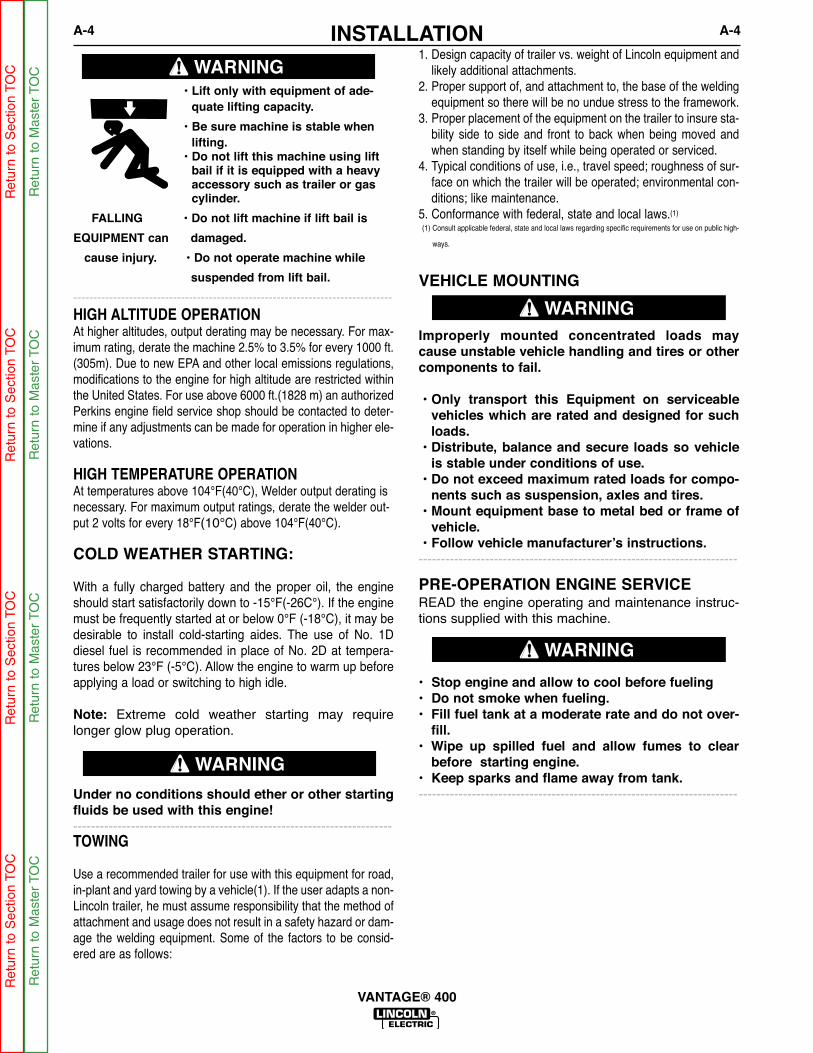
HIGH ALTITUDE OPERATIONAt higher altitudes, output derating may be necessary. For max-imum rating, derate the machine 2.5% to 3.5% for every 1000 ft.(305m). Due to new EPA and other local emissions regulations,modifications to the engine for high altitude are restricted withinthe United States. For use above 6000 ft.(1828 m) an authorizedPerkins engine field service shop should be contacted to deter-mine if any adjustments can be made for operation in higher ele-vations.
HIGH TEMPERATURE OPERATIONAt temperatures above 104°F(40°C), Welder output derating isnecessary. For maximum output ratings, derate the welder out-put 2 volts for every 18°F(10°C) above 104°F(40°C).
COLD WEATHER STARTING:
With a fully charged battery and the proper oil, the engineshould start satisfactorily down to -15°F(-26C°). If the enginemust be frequently started at or below 0°F (-18°C), it may bedesirable to install cold-starting aides. The use of No. 1Ddiesel fuel is recommended in place of No. 2D at tempera-tures below 23°F (-5°C). Allow the engine to warm up beforeapplying a load or switching to high idle.
Note: Extreme cold weather starting may requirelonger glow plug operation.
Under no conditions should ether or other startingfluids be used with this engine!------------------------------------------------------------------------TOWING
Use a recommended trailer for use with this equipment for road,in-plant and yard towing by a vehicle(1). If the user adapts a non-Lincoln trailer, he must assume responsibility that the method ofattachment and usage does not result in a safety hazard or dam-age the welding equipment. Some of the factors to be consid-ered are as follows:
1. Design capacity of trailer vs. weight of Lincoln equipment andlikely additional attachments.
2. Proper support of, and attachment to, the base of the weldingequipment so there will be no undue stress to the framework.
3. Proper placement of the equipment on the trailer to insure sta-bility side to side and front to back when being moved andwhen standing by itself while being operated or serviced.
4. Typical conditions of use, i.e., travel speed; roughness of sur-face on which the trailer will be operated; environmental con-ditions; like maintenance.
5. Conformance with federal, state and local laws.(1)
(1) Consult applicable federal, state and local laws regarding specific requirements for use on public high-
ways.
WARNING
• Lift only with equipment of ade-quate lifting capacity.
• Be sure machine is stable whenlifting.
• Do not lift this machine using liftbail if it is equipped with a heavyaccessory such as trailer or gascylinder.
FALLING • Do not lift machine if lift bail is
EQUIPMENT can damaged.
cause injury. • Do not operate machine while
suspended from lift bail.
--------------------------------------------------------------------------------VEHICLE MOUNTING
Improperly mounted concentrated loads maycause unstable vehicle handling and tires or othercomponents to fail.
• Only transport this Equipment on serviceablevehicles which are rated and designed for suchloads.
• Distribute, balance and secure loads so vehicleis stable under conditions of use.
• Do not exceed maximum rated loads for compo-nents such as suspension, axles and tires.
• Mount equipment base to metal bed or frame ofvehicle.
• Follow vehicle manufacturer’s instructions.------------------------------------------------------------------------
WARNING
PRE-OPERATION ENGINE SERVICEREAD the engine operating and maintenance instruc-tions supplied with this machine.
• Stop engine and allow to cool before fueling• Do not smoke when fueling.• Fill fuel tank at a moderate rate and do not over-
fill.• Wipe up spilled fuel and allow fumes to clear
before starting engine.• Keep sparks and flame away from tank.------------------------------------------------------------------------
WARNING
WARNING
Ret
urn
to S
ectio
n TO
CR
etur
n to
Sec
tion
TOC
Ret
urn
to S
ectio
n TO
CR
etur
n to
Sec
tion
TOC
Ret
urn
to M
aste
r TO
CR
etur
n to
Mas
ter
TOC
Ret
urn
to M
aste
r TO
CR
etur
n to
Mas
ter
TOC
INSTALLATIONA-5 A-5
VANTAGE® 400
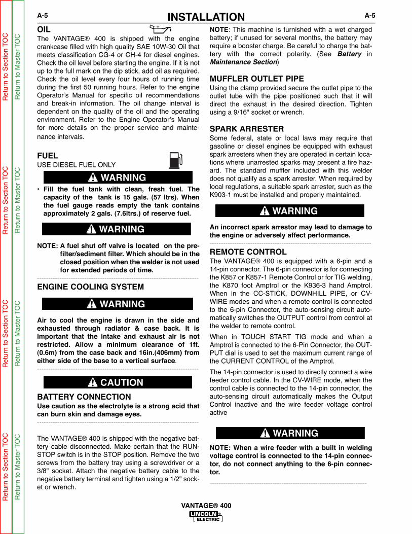
OIL The VANTAGE® 400 is shipped with the enginecrankcase filled with high quality SAE 10W-30 Oil thatmeets classification CG-4 or CH-4 for diesel engines.Check the oil level before starting the engine. If it is notup to the full mark on the dip stick, add oil as required.Check the oil level every four hours of running timeduring the first 50 running hours. Refer to the engineOperator’s Manual for specific oil recommendationsand break-in information. The oil change interval isdependent on the quality of the oil and the operatingenvironment. Refer to the Engine Operator’s Manualfor more details on the proper service and mainte-nance intervals.
FUELUSE DIESEL FUEL ONLY
• Fill the fuel tank with clean, fresh fuel. Thecapacity of the tank is 15 gals. (57 ltrs). Whenthe fuel gauge reads empty the tank containsapproximately 2 gals. (7.6ltrs.) of reserve fuel.
NOTE: A fuel shut off valve is located on the pre-filter/sediment filter. Which should be in theclosed position when the welder is not usedfor extended periods of time.
------------------------------------------------------------------------ENGINE COOLING SYSTEM
Air to cool the engine is drawn in the side andexhausted through radiator & case back. It isimportant that the intake and exhaust air is notrestricted. Allow a minimum clearance of 1ft.(0.6m) from the case back and 16in.(406mm) fromeither side of the base to a vertical surface.------------------------------------------------------------------------
BATTERY CONNECTIONUse caution as the electrolyte is a strong acid thatcan burn skin and damage eyes.------------------------------------------------------------------------
The VANTAGE® 400 is shipped with the negative bat-tery cable disconnected. Make certain that the RUN-STOP switch is in the STOP position. Remove the twoscrews from the battery tray using a screwdriver or a3/8" socket. Attach the negative battery cable to thenegative battery terminal and tighten using a 1/2" sock-et or wrench.
NOTE: This machine is furnished with a wet chargedbattery; if unused for several months, the battery mayrequire a booster charge. Be careful to charge the bat-tery with the correct polarity. (See Battery inMaintenance Section)
MUFFLER OUTLET PIPEUsing the clamp provided secure the outlet pipe to theoutlet tube with the pipe positioned such that it willdirect the exhaust in the desired direction. Tightenusing a 9/16" socket or wrench.
SPARK ARRESTERSome federal, state or local laws may require thatgasoline or diesel engines be equipped with exhaustspark arresters when they are operated in certain loca-tions where unarrested sparks may present a fire haz-ard. The standard muffler included with this welderdoes not qualify as a spark arrester. When required bylocal regulations, a suitable spark arrester, such as theK903-1 must be installed and properly maintained.
An incorrect spark arrestor may lead to damage tothe engine or adversely affect performance.------------------------------------------------------------------------REMOTE CONTROLThe VANTAGE® 400 is equipped with a 6-pin and a14-pin connector. The 6-pin connector is for connectingthe K857 or K857-1 Remote Control or for TIG welding,the K870 foot Amptrol or the K936-3 hand Amptrol.When in the CC-STICK, DOWNHILL PIPE, or CV-WIRE modes and when a remote control is connectedto the 6-pin Connector, the auto-sensing circuit auto-matically switches the OUTPUT control from control atthe welder to remote control.
When in TOUCH START TIG mode and when aAmptrol is connected to the 6-Pin Connector, the OUT-PUT dial is used to set the maximum current range ofthe CURRENT CONTROL of the Amptrol.
The 14-pin connector is used to directly connect a wirefeeder control cable. In the CV-WIRE mode, when thecontrol cable is connected to the 14-pin connector, theauto-sensing circuit automatically makes the OutputControl inactive and the wire feeder voltage controlactive
NOTE: When a wire feeder with a built in weldingvoltage control is connected to the 14-pin connec-tor, do not connect anything to the 6-pin connec-tor.
----------------------------------------------------------------------
WARNING
WARNING
CAUTION
WARNING
WARNING
WARNING
Ret
urn
to S
ectio
n TO
CR
etur
n to
Sec
tion
TOC
Ret
urn
to S
ectio
n TO
CR
etur
n to
Sec
tion
TOC
Ret
urn
to M
aste
r TO
CR
etur
n to
Mas
ter
TOC
Ret
urn
to M
aste
r TO
CR
etur
n to
Mas
ter
TOC

INSTALLATIONA-6 A-6
VANTAGE® 400
ELECTRICAL CONNECTIONS
MACHINE GROUNDINGBecause this portable engine driven welder creates itsown power, it is not necessary to connect its frame toan earth ground, unless the machine is connected topremises wiring (home, shop, etc.)
To prevent dangerous electric shock, other equipmentto which this engine driven welder supplies powermust:
• Be grounded to the frame of the welder using agrounded type plug or be double insulated.
• Do not ground the machine to a pipe that carriesexplosive or combustible material.
------------------------------------------------------------------------
When this welder is mounted on a truck or trailer, itsframe must be electrically bonded to the metal frame ofthe vehicle. Use a #8 or larger copper wire connectedbetween the machine grounding stud and the frame ofthe vehicle. When this engine driven welder is con-nected to premises wiring such as that in a home orshop, its frame must be connected to the system earthground. See further connection instructions in the sec-tion entitled Standby Power Connections as well asthe article on grounding in the latest National ElectricalCode and the local code.
In general, if the machine is to be grounded, it shouldbe connected with a #8 or larger copper wire to a solidearth ground such as a metal water pipe going into theground for at least ten feet and having no insulatedjoints, or to the metal framework of a building whichhas been effectively grounded.
The National Electrical Code lists a number of alter-nate means of grounding electrical equipment. Amachine grounding stud marked with the symbolis provided on the front of the welder.
WELDING TERMINALSThe VANTAGE® 400 is equipped with a toggle switchfor selecting "hot" welding terminal when in the "WELDTERMINALS ON" position or "cold" welding terminalwhen in the "REMOTELY CONTROLLED" position.
WARNING
WELDING OUTPUT CABLES With the engine off connect the electrode and workcables to the output studs. The welding process dic-tates the polarity of the electrode cable. These con-nections should be checked periodically and tightenedwith a 3/4" wrench.
Table A.1 lists recommended cable sizes and lengthsfor rated current and duty cycle. Length refers to thedistance from the welder to the work and back to thewelder. Cable diameters are increased for long cablelengths to reduce voltage drops.
TABLE A.1
CABLE INSTALLATIONInstall the welding cables to your VANTAGE® 400 asfollows.
1. The engine must be OFF to install welding cables.
2. Remove the flanged nuts from the output terminals.3. Connect the electrode holder and work cables to the
weld output terminals. The terminals are identifiedon the case front.
4. Tighten the flanged nuts securely.
5. Be certain that the metal piece you are welding (the“work”) is properly connected to the work clamp andcable.
6. Check and tighten the connections periodically.
• Loose connections will cause the output termi-nals to overheat. The terminals may eventuallymelt.
• Do not cross the welding cables at the output ter-minal connection. Keep the cables isolated andseparate from one another.
------------------------------------------------------------------------
TOTAL COMBINED LENGTH OFELECTRODE AND WORK CABLES
Cable Length
0-100 Ft. (0-30 meters)
100-150 Ft. (30-46 meters)
150-200 Ft. (46-61 meters)
Cable Size for 400 Amps
60% Duty Cycle2 / 0 AWG
2 / 0 AWG
3 / 0 AWG
CAUTION
Ret
urn
to S
ectio
n TO
CR
etur
n to
Sec
tion
TOC
Ret
urn
to S
ectio
n TO
CR
etur
n to
Sec
tion
TOC
Ret
urn
to M
aste
r TO
CR
etur
n to
Mas
ter
TOC
Ret
urn
to M
aste
r TO
CR
etur
n to
Mas
ter
TOC

INSTALLATIONA-7 A-7
VANTAGE® 400
All auxiliary power is protected by circuit breakers.The 120V has 20 Amp circuit breakers for each duplexreceptacle. The 120/240V Single Phase and the 240VThree-Phase have a 50 Amp 3-pole Circuit Breakerthat disconnects both hot leads and all three phasessimultaneously.
STANDBY POWER CONNECTIONS
The VANTAGE® 400 is suitable for temporary, stand-by or emergency power using the engine manufactur-er’s recommended maintenance schedule.
The VANTAGE® 400 can be permanently installed asa standby power unit for 240 VAC, 3 wire, singlephase, 50 amp service. Connections must be madeby a licensed electrician who can determine how the120/240 VAC power can be adapted to the particularinstallation and comply with all applicable electricalcodes.
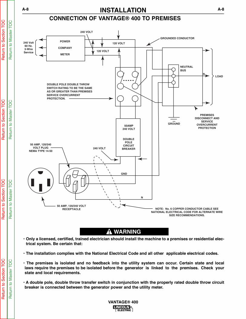
• Install the double-pole, double-throw switchbetween the power company meter and the premis-es disconnect. Switch rating must be the same orgreater than the customer’s premises disconnectand service over current protection.
• Take necessary steps to assure load is limited to thecapacity of the generator by installing a 50 amp, 240VAC double pole circuit breaker. Maximum ratedload for each leg of the 240 VAC auxiliary is 50amperes. Loading above the rated output willreduce output voltage below the allowable - 10% ofrated voltage which may damage appliances orother motor-driven equipment and may result inoverheating of the engine and/or alternator wind-ings.
• Install a 50 amp, 120/240 VAC plug (NEMA Type14-50P) to the double-pole circuit breaker using No.6, 4 conductor cable of the desired length. (The 50amp, 120/240 VAC plug is available in the optionalK802R plug kit or as part number T12153-9.)
• Plug this cable into the 50 Amp, 120/240 Volt recep-tacle on the case front.
AUXILIARY POWER RECEPTACLES
Start the engine and set the “IDLER” control switch tothe “High Idle” mode. Voltage is now correct at thereceptacles for auxiliary power. This must be donebefore a tripped GFCI receptacle can be reset properly.See the MAINTENANCE section for more detailedinformation on testing and resetting the GFCI recepta-cle.
The auxiliary power of the VANTAGE® 400 consists oftwo 20 Amp-120 VAC (5-20R) duplex receptacles withGFCI protection, one 50 Amp 120/240 VAC (14-50R)receptacle and one 50 Amp 240VAC Three-Phase (15-50R) receptacle.
The auxiliary power capacity is 12,000 watts Peak,11,000 Watts Continuous of 60 Hz, single phase power.The auxiliary power capacity rating in watts is equiva-lent to volt-amperes at unity power factor. The max per-missible current of the 240 VAC output is 50amps.
The 240 VAC output can be split to provide two sepa-rate 120 VAC outputs with a max permissible current of50 Amps per output to two separate 120 VAC branchcircuits (these circuits cannot be paralleled). Outputvoltage is within ± 10% at all loads up to rated capacity.
The Three-Phases auxiliary power capacity is 17,000watts peak, 19,000 watts continuous. The maximumcurrent is 45 amps.
120 V GFCI DUPLEX RECEPTACLES
A GFCI (Ground Fault Circuit Interrupter) electricalreceptacle is a device to protect against electric shockshould a piece of defective equipment connected to itdevelop a ground fault. If this situation should occur, theGFCI will trip, removing voltage from the output of thereceptacle. If a GFCI receptacle is tripped see theMAINTENANCE section for detailed information ontesting and resetting it. A GFCI receptacle should beproperly tested at least once every month.
The 120 V auxiliary power receptacles should only beused with three wire grounded type plugs or approveddouble insulated tools with two wire plugs. The currentrating of any plug used with the system must be at leastequal to the current capacity of the associated recepta-cle.
NOTE: The 240 V receptacle has two 120 V circuits,but are of opposite polarities and cannot be paralleled.
Ret
urn
to S
ectio
n TO
CR
etur
n to
Sec
tion
TOC
Ret
urn
to S
ectio
n TO
CR
etur
n to
Sec
tion
TOC
Ret
urn
to M
aste
r TO
CR
etur
n to
Mas
ter
TOC
Ret
urn
to M
aste
r TO
CR
etur
n to
Mas
ter
TOC
INSTALLATIONA-8 A-8
VANTAGE® 400
CONNECTION OF VANTAGE® 400 TO PREMISES
WARNING• Only a licensed, certified, trained electrician should install the machine to a premises or residential elec-
trical system. Be certain that:
• The installation complies with the National Electrical Code and all other applicable electrical codes.
• The premises is isolated and no feedback into the utility system can occur. Certain state and locallaws require the premises to be isolated before the generator is linked to the premises. Check yourstate and local requirements.
• A double pole, double throw transfer switch in conjunction with the properly rated double throw circuitbreaker is connected between the generator power and the utility meter.
240 Volt
60 Hz.
3-Wire
Service
POWER
COMPANY
METER
240 VOLT
120 VOLT
120 VOLT
LOADN
NEUTRAL
BUS
GROUND
PREMISES
DISCONNECT AND
SERVICE
OVERCURRENT
PROTECTION
GND
N
NOTE: No. 6 COPPER CONDUCTOR CABLE SEE
NATIONAL ELECTRICAL CODE FOR ALTERNATE WIRE
SIZE RECOMMENDATIONS.
240 VOLT
GROUNDED CONDUCTOR
50AMP
240 VOLT
DOUBLE
POLE
CIRCUIT
BREAKER
DOUBLE POLE DOUBLE THROW
SWITCH RATING TO BE THE SAME
AS OR GREATER THAN PREMISES
SERVICE OVERCURRENT
PROTECTION.
50 AMP, 120/240
VOLT PLUG
NEMA TYPE 14-50
50 AMP, 120/240 VOLT
RECEPTACLE
Ret
urn
to S
ectio
n TO
CR
etur
n to
Sec
tion
TOC
Ret
urn
to S
ectio
n TO
CR
etur
n to
Sec
tion
TOC
Ret
urn
to M
aste
r TO
CR
etur
n to
Mas
ter
TOC
Ret
urn
to M
aste
r TO
CR
etur
n to
Mas
ter
TOC

INSTALLATIONA-9 A-9
VANTAGE® 400
CONNECTION OF LINCOLN ELEC-TRIC WIRE FEEDERS
CONNECTION OF LN-7 OR LN-8 TO THEVANTAGE® 400
1. Shut the welder off.
2. Connect the LN-7 or LN-8 per instructions on theappropriate connection diagram in Section F.
3. Set the "WIRE FEEDER VOLTMETER" switch toeither "+" or "-" as required by the electrode beingused.
4. Set the "MODE" switch to the "CV WIRE " position.5. Set the "ARC CONTROL" knob to "0" initially and
adjust to suit.
6. Set the "WELD TERMINALS" switch to the"REMOTELY CONTROLLED" position.
7. Set the "IDLE" switch to the "HIGH" position.
CONNECTION OF LN-15 TO THE VAN-TAGE® 400
1. Shut the welder off.
2. For electrode Positive, connect the electrode cableto the "+" terminal of the welder and work cable tothe "-" terminal of the welder. For electrodeNegative, connect the electrode cable to the "-" ter-minal of the welder and work cable to the "+" ter-minal of the welder.
3. Across The-Arc Model:
• Attach the single lead from the front of the LN-15to work using the spring clip at the end of thelead. This is a control lead to supply current tothe wire feeder motor; it does not carry weldingcurrent.
• Set the "WELD TERMINALS" switch to "WELDTERMINALS ON".
• When the gun trigger is closed, the current sens-ing circuit will cause the VANTAGE® 400 engineto go to the high idle speed, the wire will begin tofeed and the welding process started. Whenwelding is stopped, the engine will revert to lowidle speed after approximately 12 secondsunless welding is resumed.
4. Control Cable Model:
• Connect Control Cable between Engine Welderand Feeder.
• Set the "WELD TERMINALS" switch to"REMOTELY CONTROLLED"
• Set the MODE switch to the "CV-WIRE " position.
• Set the "WIRE FEEDER VOLTMETER" switch toeither "+" or "-" as required by the electrode polar-ity being used.
• Set the "ARC CONTROL" knob to "0" initially andadjust to suit.
• Set the "IDLE" switch to the "AUTO" position.
• When the gun trigger is closed, the current sens-ing circuit will cause the VANTAGE® 400 engineto go to the high idle speed, the wire will begin tofeed and the welding process started. When weld-ing is stopped, the engine will revert to low idlespeed after approximately 12 seconds unlesswelding is resumed.
Ret
urn
to S
ectio
n TO
CR
etur
n to
Sec
tion
TOC
Ret
urn
to S
ectio
n TO
CR
etur
n to
Sec
tion
TOC
Ret
urn
to M
aste
r TO
CR
etur
n to
Mas
ter
TOC
Ret
urn
to M
aste
r TO
CR
etur
n to
Mas
ter
TOC

INSTALLATIONA-10 A-10
VANTAGE® 400
CONNECTION OF SPOOL GUN (K487-25)AND COBRAMATIC TO VANTAGE® 400
• Shut the welder off.
• Connect per instructions on the appropriate con-
nection diagram in Section C.
CONNECTION OF PRINCE XL SPOOL GUNTO THE VANTAGE® 400
Connection of the Prince XL Spool Gun requires theuse of the K1849-1 Adapter Module.
• Shut the Welder off.
• For electrode Positive, connect the electrode cableto the "+" terminal of the welder and work cable tothe "-" terminal of the welder. For electrode Negative,connect the electrode cable "-" terminal of the welderand work cable to the "+" terminal of the welder.
• Connect the Control Cable of the Spool Gun to theAdapter Module and connect the Control Cable ofthe Adapter Module to the Welder.
• Connect the Gas Hose.
• Set the MODE switch to the "CV-WIRE " position.
• Set the "WELD TERMINALS" switch to "WELD TER-MINALS ON".
• Set the "ARC CONTROL" knob to "0" initially andadjust to suit.
• Set the “IDLE” switch to the “HIGH” position.
See Section C for additional Connection Diagrams.
Connection of the LN-25 to the VANTAGE® 400Shut off welder before making any electrical con-nections.------------------------------------------------------------------------The LN-25 with or without an internal contactor may beused with the VANTAGE® 400. See the appropriateconnection diagram in Section F.
NOTE: The LN-25 (K431) Remote Control Module and(K432) Remote Cable are not recommended for usewith the VANTAGE® 400.
1. Shut the welder off.
2. For electrode Positive, connect the electrode cablefrom the LN-25 to the "+" terminal of the welderand work cable to the "-" terminal of the welder. Forelectrode Negative, connect the electrode cablefrom the LN-25 to the "-" terminal of the welder andwork cable to the "+" terminal of the welder.
3. Attach the single lead from the front of the LN-25to work using the spring clip at the end of the lead.This is a control lead to supply current to the wirefeeder motor; it does not carry welding current.
4. Set the MODE switch to the "CV-WIRE " position.
5. Set the "WELD TERMINALS" switch to "WELDTERMINALS ON"
6. Set the "ARC CONTROL" knob to "0" initially andadjust to suit.
7. Set the "IDLE" switch to the "AUTO" position.When not welding, the VANTAGE® 400 engine willbe at the low idle speed. If you are using an LN-25with an internal contactor, the electrode is not ener-gized until the gun trigger is closed.
8. When the gun trigger is closed, the current sensingcircuit will cause the VANTAGE® 400 engine to goto the high idle speed, the wire will begin to feedand the welding process started. When welding isstopped, the engine will revert to low idle speedafter approximately 12 seconds unless welding isresumed.
If you are using an LN-25 without an internal con-tactor, the electrode will be energized when theVANTAGE® 400 is started.------------------------------------------------------------------------
WARNING
CAUTION
Ret
urn
to S
ectio
n TO
CR
etur
n to
Sec
tion
TOC
Ret
urn
to S
ectio
n TO
CR
etur
n to
Sec
tion
TOC
Ret
urn
to M
aste
r TO
CR
etur
n to
Mas
ter
TOC
Ret
urn
to M
aste
r TO
CR
etur
n to
Mas
ter
TOC
TABLE OF CONTENTS - OPERATION SECTIONB-1 B-1
VANTAGE® 400
Operation . . . . . . . . . . . . . . . . . . . . . . . . . . . . . . . . . . . . . . . . . . . . . . . . . . . . . . . . . . . . . . . . . . . . . . . . . . . . . .B-1
Safety Precautions . . . . . . . . . . . . . . . . . . . . . . . . . . . . . . . . . . . . . . . . . . . . . . . . . . . . . . . . . . . . . . . . . . .B-2
General Description . . . . . . . . . . . . . . . . . . . . . . . . . . . . . . . . . . . . . . . . . . . . . . . . . . . . . . . . . . . . . . . . . . .B-2
For Auxiliary Power . . . . . . . . . . . . . . . . . . . . . . . . . . . . . . . . . . . . . . . . . . . . . . . . . . . . . . . . . . . . . . . . . . .B-2
Engine Operation . . . . . . . . . . . . . . . . . . . . . . . . . . . . . . . . . . . . . . . . . . . . . . . . . . . . . . . . . . . . . . . . . . . . .B-2
Add Fuel . . . . . . . . . . . . . . . . . . . . . . . . . . . . . . . . . . . . . . . . . . . . . . . . . . . . . . . . . . . . . . . . . . . . . . . .B-2
Break in Period . . . . . . . . . . . . . . . . . . . . . . . . . . . . . . . . . . . . . . . . . . . . . . . . . . . . . . . . . . . . . . . . . . .B-2
Welder Controls . . . . . . . . . . . . . . . . . . . . . . . . . . . . . . . . . . . . . . . . . . . . . . . . . . . . . . . . . . . . . . . . . . .B-3,B-4
Engine Controls . . . . . . . . . . . . . . . . . . . . . . . . . . . . . . . . . . . . . . . . . . . . . . . . . . . . . . . . . . . . . . . . . . . . . .B-5
Fuel Consumption . . . . . . . . . . . . . . . . . . . . . . . . . . . . . . . . . . . . . . . . . . . . . . . . . . . . . . . . . . . . . . . . .B-5
Starting and Stopping the Engine . . . . . . . . . . . . . . . . . . . . . . . . . . . . . . . . . . . . . . . . . . . . . . . . .B-5, B-6
Welding Operation . . . . . . . . . . . . . . . . . . . . . . . . . . . . . . . . . . . . . . . . . . . . . . . . . . . . . . . . . . . . . . . . . . . .B-6
Duty Cycle and Electrode Information . . . . . . . . . . . . . . . . . . . . . . . . . . . . . . . . . . . . . . . . . . . . . . . . . .B-6
Constant Current (Stick) Welding . . . . . . . . . . . . . . . . . . . . . . . . . . . . . . . . . . . . . . . . . . . . . . . . . . . . .B-6
Downhill Pipe (Stick) Welding . . . . . . . . . . . . . . . . . . . . . . . . . . . . . . . . . . . . . . . . . . . . . . . . . . . . . . . .B-6
TIG Welding . . . . . . . . . . . . . . . . . . . . . . . . . . . . . . . . . . . . . . . . . . . . . . . . . . . . . . . . . . . . . . . . . . . . . .B-7
Typical Current Ranges for Tungsten Electrodes . . . . . . . . . . . . . . . . . . . . . . . . . . . . . . . . . . . . . . . . .B-7
Wire Welding-CV . . . . . . . . . . . . . . . . . . . . . . . . . . . . . . . . . . . . . . . . . . . . . . . . . . . . . . . . . . . . . . . . . .B-8
Arc Gouging . . . . . . . . . . . . . . . . . . . . . . . . . . . . . . . . . . . . . . . . . . . . . . . . . . . . . . . . . . . . . . . . . . . . . .B-8
Auxiliary Power . . . . . . . . . . . . . . . . . . . . . . . . . . . . . . . . . . . . . . . . . . . . . . . . . . . . . . . . . . . . . . . . . . . . . . .B-8
Simultaneous Welding and Power Loads . . . . . . . . . . . . . . . . . . . . . . . . . . . . . . . . . . . . . . . . . . . . . . .B-8
Extension Cord Recommendations . . . . . . . . . . . . . . . . . . . . . . . . . . . . . . . . . . . . . . . . . . . . . . . . . . . .B-8
Ret
urn
to M
aste
r TO
CR
etur
n to
Mas
ter
TOC
Ret
urn
to M
aste
r TO
CR
etur
n to
Mas
ter
TOC
THEORY OF OPERATIONB-2 B-2
VANTAGE® 400
SAFETY PRECAUTIONS
Do not attempt to use this equipment until youhave thoroughly read the engine manufacturer’smanual supplied with your welder. It includesimportant safety precautions, detailed enginestarting, operating and maintenance instructions,and parts lists.------------------------------------------------------------------------
ELECTRIC SHOCK can kill.• Do not touch electrically live parts or
electrode with skin or wet clothing.• Insulate yourself from work and
ground• Always wear dry insulating gloves.
• Always operate the welder with the hinged doorclosed and the side panels in place.
• Read carefully the Safety Precautions pagebefore operating this machine. Always followthese and any other safety procedures includedin this manual and in the Engine InstructionManual.
GENERAL DESCRIPTIONThe VANTAGE® 400 is a diesel engine powered DCmulti-process welding power source and 120 / 240 voltAC power generator. The engine drives a generatorthat supplies three phase power for the DC welding cir-cuit, single phase and Three Phase power for the ACauxiliary outlets. The DC welding control system uses
state of the art Chopper Technology (CT™) for superi-or welding performance.
The Vantage® 400 is fitted with a selectableVRD(Voltage Reduction Device). The VRD operates inthe CC-Stick mode reducing the OCV to <13 volts,increasing operator safety when welding is performedin environments with increased hazard of electricshock.
FOR AUXILIARY POWER:Start the engine and set the IDLERcontrol switch to the desired operating mode. Fullpower is available regardless of the welding controlsettings providing no welding current is being drawn.
ENGINE OPERATIONBefore Starting the Engine:
• Be sure the machine is on a level surface.• Open side engine door and remove the engine oil
dipstick and wipe it with a clean cloth. Reinsert thedipstick and check the level on the dipstick.
• Add oil (if necessary) to bring the level up to the fullmark. Do not overfill. Close engine door.
• Check radiator for proper coolant level. (Fill if nec-essary).
• See Engine Owner’s Manual for specific oil andcoolant recommendations.
ADD FUEL• Stop engine while fueling.• Do not smoke when fueling.• Keep sparks and flame away
from tank.• Do not leave unattended while
fueling.• Wipe up spilled fuel and allow
fumes to clear before startingengine.
• Do not overfill tank, fuel expan-sion may cause overflow.
DIESEL FUEL ONLY------------------------------------------------------------------------• Remove the fuel tank cap.
• Fill the tank. DO NOT FILL THE TANK TO THEPOINT OF OVERFLOW.
• Replace the fuel cap and tighten securely.
• See Engine Owner’s Manual for specific fuel recom-mendations.
BREAK-IN PERIOD
The engine will use a small amount of oil during its“break-in” period. The break-in period is about 50 run-ning hours.
Check the oil every four hours during break-in. Changethe oil after the first 50 hours of operation and every200 hours thereafter. Change the oil filter at each oilchange. During break-in, subject the Welder to moderateloads. Avoid long periods running at idle. Beforestopping the engine, remove all loads and allowthe engine to cool several minutes.------------------------------------------------------------------------
WARNING
WARNING
CAUTION
DIESEL FUELcan cause fire.
Ret
urn
to S
ectio
n TO
CR
etur
n to
Sec
tion
TOC
Ret
urn
to S
ectio
n TO
CR
etur
n to
Sec
tion
TOC
Ret
urn
to M
aste
r TO
CR
etur
n to
Mas
ter
TOC
Ret
urn
to M
aste
r TO
CR
etur
n to
Mas
ter
TOC

THEORY OF OPERATIONB-3 B-3
VANTAGE® 400
WELDING CONTROLS (Figure B.1)
1. OUTPUT CONTROL- The OUTPUT dial is usedto preset the output voltage or current as displayedon the digital meters for the four welding modes.When in the CC-STICK, DOWNHILL PIPE or CV-WIRE modes and when a remote control is connect-ed to the 6-Pin or 14-Pin Connector, the auto-sens-ing circuit automatically switches the OUTPUTCONTROL from control at the welder to the remotecontrol.
In the CV-WIRE mode, if the feeder being used hasa voltage control when the wire feeder control cableis connected to the 14-Pin Connector, the auto-sens-ing circuit automatically makes OUTPUT CONTROLinactive and the wire feeder voltage control active.Otherwise, the OUTPUT CONTROL is used to pre-set the voltage
When in the TOUCH START TIG mode and when anAmptrol is connected to the 6-Pin Connector, theOUTPUT dial is used to set the maximum currentrange of the CURRENT CONTROL of the Amptrol.
2. DIGITAL OUTPUT METERS-The digital metersallow the output voltage (CV-WIRE mode) or cur-rent (CC-STICK,DOWN HILL PIPE and TIG modes)to be set prior to welding using the OUTPUT controldial. During welding, the meter display the actualoutput voltage (VOLTS) and current (AMPS). Amemory feature holds the display of both meters onfor seven seconds after welding is stopped. Thisallows the operator to read the actual current andvoltage just prior to when welding was ceased.
While the display is being held the left-most deci-mal point in each display will be flashing. The accu-racy of the meters is +/- 3%.
3. WELD MODE SELECTOR SWITCH-(Provides four selectable welding modes)
CV-WIREDOWNHILL PIPECC-STICKTOUCH START TIG
1
9
11
20
7
410
5
8
12
13
15
19
6
21
14
18
17
16
2
3
FIGURE B.1
Ret
urn
to S
ectio
n TO
CR
etur
n to
Sec
tion
TOC
Ret
urn
to S
ectio
n TO
CR
etur
n to
Sec
tion
TOC
Ret
urn
to M
aste
r TO
CR
etur
n to
Mas
ter
TOC
Ret
urn
to M
aste
r TO
CR
etur
n to
Mas
ter
TOC

THEORY OF OPERATIONB-4 B-4
VANTAGE® 400
4. ARC CONTROL- The ARC CONTROL dial is active inthe CV-WIRE, CC-STICK and DOWNHILL PIPE modes,and has different functions in these modes. This control isnot active in the TIG mode.
CC-STICK mode: In this mode, the ARC CONTROL dialsets the short circuit current (arc-force) during stick weldingto adjust for a soft or crisp arc. Increasing the dial from –10(soft) to +10 (crisp) increases the short circuit current andprevents sticking of the electrode to the plate while welding.This can also increase spatter. It is recommended that theARC CONTROL be set to the minimum number withoutelectrode sticking. Start with a setting at 0.
DOWNHILL PIPE mode: In this mode, the ARC CONTROLdial sets the short circuit current (arc-force) during stick weld-ing to adjust for a soft or a more forceful digging arc (crisp).Increasing the number from –10 (soft) to +10 (crisp) increas-es the short circuit current which results in a more forcefuldigging arc. Typically a forceful digging arc is preferred forroot and hot passes. A softer arc is preferred for fill and cappasses where weld puddle control and deposition ("stacking"of iron) are key to fast travel speeds. It is recommended thatthe ARC CONTROL be set initially at 0.
CV-WIRE mode: In this mode, turning the ARC CONTROLclock wise from –10 (soft) to +10 (crisp) changes the arc fromsoft and washed-in to crisp and narrow. It acts as an induc-tance/pinch control. The proper setting depends on the pro-cedure and operator preference. Start with a setting of 0.
5. WELD OUTPUT TERMINALS WITH FLANGENUT- Provides a connection point for the electrode andwork cables.
6. GROUND STUD- Provides a connection point forconnecting the machine case to earth ground.
7. 14-PIN CONNECTOR- For attaching wire feeder con-trol cables. Includes contactor closure circuit, auto-sensingremote control circuit, and 120V and 42V power. The remotecontrol circuit operates the same as the 6 Pin Amphenol.
8. 6-PIN CONNECTOR- For attaching optional remotecontrol equipment. Includes auto-sensing remote control cir-cuit.
9. WELD TERMINALS CONTROL SWITCH- In theWELD TERMINALS ON position, the output is electricallyhot all the time. In the REMOTELY CONTROLLED posi-tion, the output is controlled by a wire feeder or amptroldevice, and is electrically off until a remote switch isdepressed.
10. WIRE FEEDER VOLTMETER SWITCH:Matches the polarity of the wire feeder voltmeter tothe polarity of the electrode.
11. VRD (Voltage Reduction Device) INDICA-TOR LIGHTS- On the front panel of the Vantage400 are two indicator lights. A red light when lit indi-cates OCV(Open Circuit Voltage) is equal to or greaterthan 30V and a green light when lit indicatesOCV(Open Circuit Voltage) is less than 30V.
The VRD “On/Off” switch inside the control panelmust be “On” for the VRD function to be active andthe lights to be enabled. When the machine is firststarted with VRD enabled, both lights will illuminatefor 5 seconds.
These lights monitor the OCV(Open Circuit Voltage)and weld voltage at all times. In the CC-Stick modewhen not welding the green light will illuminate indi-cating that the VRD has reduced the OCV to less than30V. During welding the red light will illuminate when-ever the arc voltage is equal to or greater than 30V.This means that the red and green light may alternatedepending on the weld voltage. This is normal opera-tion.
If the red light remains illuminated when not weldingin the CC-stick mode, the VRD is not functioningproperly. Please refer to your local field service shopfor service.
If the VRD is turned “On” and the lights don’t come“On”, refer to the trouble shooting section.
TABLE B.1VRD INDICATOR LIGHTS
MODE VRD "ON" VRD "OFF" CC-STICK OCV Green (OCV Reduced)
While Red or GreenWelding (Depends on Weld Voltage) *
CV-WIRE OCV Red (OCV Not Reduced)Weld Terminals OnRed (OCV Not Reduced)Weld Terminals Remotely ControlledGun Trigger ClosedGreen (No OCV)Weld Terminals Remotely ControlledGun Trigger Open No Lights
While Red or GreenWelding (Depends on Weld Voltage) *
PIPE OCV Green (No Output)While Not Applicable (No Output)Welding
ARC GOUGING OCV Green (No Output)While Not Applicable (No Output)Welding
TIG OCV Green (Process is Low Voltage)While Green (Process is Low Voltage)Welding
* It is normal for the lights to alternate between colors while welding.
Ret
urn
to S
ectio
n TO
CR
etur
n to
Sec
tion
TOC
Ret
urn
to S
ectio
n TO
CR
etur
n to
Sec
tion
TOC
Ret
urn
to M
aste
r TO
CR
etur
n to
Mas
ter
TOC
Ret
urn
to M
aste
r TO
CR
etur
n to
Mas
ter
TOC

THEORY OF OPERATIONB-5 B-5
VANTAGE® 400
TYPICAL VANTAGE® 400 FUEL CONSUMPTIONTABLE B.2
PERKINS Gal./Hr (Liters/Hr)
.26 (.97)
.42 (1.57)
1.18 (4.46)1.24 (4.68).90 (3.42)
Running Time for15 gallons / hours
58.59
36.06
12.7412.1416.62
Low Idle - No Load1400 R.P.M.High Idle - No Load1880 R.P.M.DC Weld Output400 Amps @ 36 Volts 17,000 Watts 3 Phase11,000 Watts 1 Phase
NOTE: This data is for reference only. Fuel consump-tion is approximate and can be influenced by many fac-tors, including engine maintenance, environmentalconditions and fuel quality.
ENGINE CONTROLS: 12. RUN/STOP SWITCH - RUN position energizes the
engine prior to starting. STOP position stops the engine.The oil pressure interlock switch prevents battery drain ifthe switch is left in the RUN position and the engine isnot operating.
13. GLOW PLUG PUSH BUTTON -• When pushed activates the glow plugs. Glow plug
should not be activated for more than 20 seconds con-tinuously.
14. START PUSH BUTTON - Energizes the startermotor to crank the engine.
15. IDLER SWITCH- Has two positions as follows:1) In the HIGH position, the engine runs at the high idle
speed controlled by the engine governor.2) In the AUTO position, the idler operates as follows:• When switched from HIGH to AUTO or after starting the
engine, the engine will operate at full speed for approx-imately 12 seconds and then go to low idle speed.
• When the electrode touches the work or power isdrawn for lights or tools (approximately 100 Watts min-imum), the engine accelerates and operates at fullspeed.
• When welding ceases or the AC power load is turnedoff, a fixed time delay of approximately 12 secondsstarts. If the welding or AC power load is not restartedbefore the end of the time delay, the idler reduces theengine speed to low idle speed.
• The engine will automatically return to high idle speedwhen there is welding load or AC power load reapplied.
16. ELECTRIC FUEL GAUGE- The electric fuel gaugegives accurate and reliable indication as to how muchfuel is in the fuel tank.
17. ENGINE HOUR METER- Displays the total timethat the engine has been running. This meter is usefulfor scheduling prescribed maintenance.
18. ENGINE PROTECTION LIGHT- A warning indi-cator light for Low Oil Pressure and/or Coolant OverTemperature.The light is off when the systems are func-tioning properly. The light will come on and the enginewill shutdown when there is Low Oil Pressure and/or theCoolant is Over Temperature.
Note: The light remains off when the RUN-STOP switchis in the "ON" position prior to starting the engine.However if the engine is not started within 60 secondsthe light will come on. When this happens the RUN-STOP switch must be returned to the "OFF" position toreset the engine protection system and light.
19. BATTERY CHARGING LIGHT- A warning indica-tor light for Low/No battery charge. The light is off whenthe systems are functioning properly. The light will comeon if there is a Low/No battery condition but the machinewill continue to run.
Note: The light may or may not come on when the RUN-STOP switch is in the "ON" position. It will come on dur-ing cranking and stay on until the engine starts. Afterstarting the engine the light will go off unless a Low/Nobattery charge condition exists.
20. COOLANT TEMPERATURE GAUGE-A indica-tor of engine coolant temperature.
21. OIL PRESSURE GAUGE- A indicator of engineOil Pressure.
STARTING THE ENGINE1. Remove all plugs connected to the AC power receptacles.2. Set IDLER switch to AUTO.
3. Press Glow Plug Button and hold 15 to 20 seconds.4. Set the RUN/STOP switch to RUN.5. Press START button until the engine starts or for up to
10 seconds. Continue to hold the glow plug button for upto an additional 10 seconds.
6. Release the engine START button immediately when theengine starts.
7. The engine will run at high idle speed for approximately 12seconds and then drop to low idle speed. Allow the engineto warm up at low idle for several minutes before applyinga load and/or switching to high idle. Allow a longerwarm up time in cold weather.
Ret
urn
to S
ectio
n TO
CR
etur
n to
Sec
tion
TOC
Ret
urn
to S
ectio
n TO
CR
etur
n to
Sec
tion
TOC
Ret
urn
to M
aste
r TO
CR
etur
n to
Mas
ter
TOC
Ret
urn
to M
aste
r TO
CR
etur
n to
Mas
ter
TOC

THEORY OF OPERATIONB-6 B-6
VANTAGE® 400
WELDER OPERATIONDUTY CYCLE
Duty Cycle is the percentage of time the load is beingapplied in a 10 minute period. For example a 60% dutycycle, represents 6 minutes of load and 4 minutes of noload in a 10 minute period.
ELECTRODE INFORMATION
For any electrode the procedures should be kept with-in the rating of the machine. For information on elec-trodes and their proper application see (www.lincoln-electric.com) or the appropriate Lincoln publication.
The VANTAGE® 400 can be used with a broad range ofDC stick electrodes. The MODE switch provides two stickwelding settings as follows:
CONSTANT CURRENT (CC-STICK) WELDING
The CC-STICK position of the MODE switch is designedfor horizontal and vertical-up welding with all types ofelectrodes, especially low hydrogen. The OUTPUT CON-TROL dial adjusts the full output range for stick welding.
NOTE: If the unit fails to start turn Run/Stop switch tooff and repeat step 3 through step 7 after wait-ing 30 seconds.
• Do not allow the starter motor to run continuouslyfor more than 20 seconds.
• Do not push the START button while the engineis running because this can damage the ring gearand/or the starter motor.
• IF the Engine Protection or Battery ChargingLights do “not” turn off shortly after starting theengine shut off the engine immediately and deter-mine the cause.
-----------------------------------------------------------------------NOTE: When starting for the first time, or after anextended period of time of not operating, it will takelonger than normal to start because the fuel pump hasto fill the fuel system. For best results, bleed the fuelsystem as indicated in the Maintenance Section of thismanual.
STOPPING THE ENGINERemove all welding and auxiliary power loads andallow the engine to run at low idle speed for a few min-utes to cool the engine.
STOP the engine by placing the RUN-STOP switch inthe STOP position.
NOTE: A fuel shut off valve is located on the fuel pre-filter.
CAUTION
The ARC CONTROL dial sets the short circuit current(arc-force) during stick welding to adjust for a soft orcrisp arc. Increasing the number from -10(soft) to+10(crisp) increases the short circuit current and pre-vents sticking of the electrode to the plate while welding.This can also increase spatter. It is recommended thatthe ARC CONTROL be set to the minimum number with-out electrode sticking. Start with the dial set at 0.
NOTE: Due to the low OCV with the VRD on, a veryslight delay during striking of the electrodes mayoccur. Due to the requirement of the resistance inthe circuit to be low for a VRD to operate, a goodmetal-to-metal contact must be made between themetal core of the electrode and the job. A poor con-nection anywhere in the welding output circuit maylimit the operation of the VRD. This includes a goodconnection of the work clamp to the job. The workclamp should be connected as close as practical towhere the welding will be performed.
A. For New ElectrodesE6010 - Touch, Lift to Start the ArcE7018, E7024 - Touch, Rock Back and Forth in
Joint, Lift .
Once the arc is started, normal welding techniquefor the application is then used.
B. For Re-Striking ElectrodesSome electrodes form a cone at the end of the elec-trode after the welding arc has been broken, partic-ularly iron powder and low hydrogen electrodes.This cone will need to be broken off in order to havethe metal core of the electrode make contact.
E6010 - Push, Twist in Joint, LiftE7018, E7024 - Push, Rock Back and Forth in
Joint, Lift.
Once the arc is started, normal welding techniquefor the application is then used.
For other electrodes the above techniques shouldbe tried first and varied as needed to suit operatorpreference. The goal for successful starting is goodmetal to metal contact.
For indicator light operation, see Table B.1.
DOWNHILL PIPE Welding
This slope controlled setting is intended for "out-of-position" and "down hill" pipe welding where the oper-ator would like to control the current level by changingthe arc length.
Ret
urn
to S
ectio
n TO
CR
etur
n to
Sec
tion
TOC
Ret
urn
to S
ectio
n TO
CR
etur
n to
Sec
tion
TOC
Ret
urn
to M
aste
r TO
CR
etur
n to
Mas
ter
TOC
Ret
urn
to M
aste
r TO
CR
etur
n to
Mas
ter
TOC
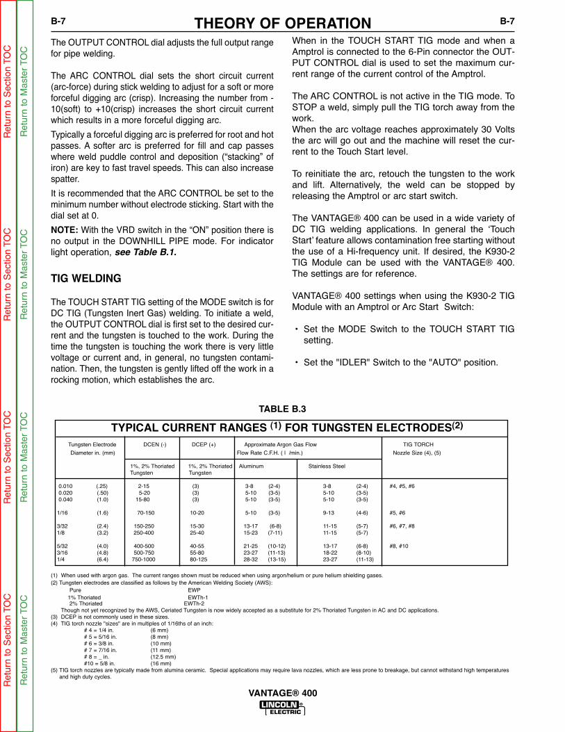
THEORY OF OPERATIONB-7 B-7
VANTAGE® 400
When in the TOUCH START TIG mode and when aAmptrol is connected to the 6-Pin connector the OUT-PUT CONTROL dial is used to set the maximum cur-rent range of the current control of the Amptrol.
The ARC CONTROL is not active in the TIG mode. ToSTOP a weld, simply pull the TIG torch away from thework. When the arc voltage reaches approximately 30 Voltsthe arc will go out and the machine will reset the cur-rent to the Touch Start level.
To reinitiate the arc, retouch the tungsten to the workand lift. Alternatively, the weld can be stopped byreleasing the Amptrol or arc start switch.
The VANTAGE® 400 can be used in a wide variety ofDC TIG welding applications. In general the ‘TouchStart’ feature allows contamination free starting withoutthe use of a Hi-frequency unit. If desired, the K930-2TIG Module can be used with the VANTAGE® 400.The settings are for reference.
VANTAGE® 400 settings when using the K930-2 TIGModule with an Amptrol or Arc Start Switch:
• Set the MODE Switch to the TOUCH START TIGsetting.
• Set the "IDLER" Switch to the "AUTO" position.
The OUTPUT CONTROL dial adjusts the full output rangefor pipe welding.
The ARC CONTROL dial sets the short circuit current(arc-force) during stick welding to adjust for a soft or moreforceful digging arc (crisp). Increasing the number from -10(soft) to +10(crisp) increases the short circuit currentwhich results in a more forceful digging arc.
Typically a forceful digging arc is preferred for root and hotpasses. A softer arc is preferred for fill and cap passeswhere weld puddle control and deposition (“stacking” ofiron) are key to fast travel speeds. This can also increasespatter.
It is recommended that the ARC CONTROL be set to theminimum number without electrode sticking. Start with thedial set at 0.
NOTE: With the VRD switch in the “ON” position there isno output in the DOWNHILL PIPE mode. For indicatorlight operation, see Table B.1.
TIG WELDING
The TOUCH START TIG setting of the MODE switch is forDC TIG (Tungsten Inert Gas) welding. To initiate a weld,the OUTPUT CONTROL dial is first set to the desired cur-rent and the tungsten is touched to the work. During thetime the tungsten is touching the work there is very littlevoltage or current and, in general, no tungsten contami-nation. Then, the tungsten is gently lifted off the work in arocking motion, which establishes the arc.
TYPICAL CURRENT RANGES (1) FOR TUNGSTEN ELECTRODES(2)
Tungsten Electrode DCEN (-) DCEP (+) Approximate Argon Gas Flow TIG TORCH
Diameter in. (mm) Flow Rate C.F.H. ( l /min.) Nozzle Size (4), (5)
1%, 2% Thoriated 1%, 2% Thoriated Aluminum Stainless SteelTungsten Tungsten
0.010 (.25) 2-15 (3) 3-8 (2-4) 3-8 (2-4) #4, #5, #60.020 (.50) 5-20 (3) 5-10 (3-5) 5-10 (3-5)0.040 (1.0) 15-80 (3) 5-10 (3-5) 5-10 (3-5)
1/16 (1.6) 70-150 10-20 5-10 (3-5) 9-13 (4-6) #5, #6
3/32 (2.4) 150-250 15-30 13-17 (6-8) 11-15 (5-7) #6, #7, #81/8 (3.2) 250-400 25-40 15-23 (7-11) 11-15 (5-7)
5/32 (4.0) 400-500 40-55 21-25 (10-12) 13-17 (6-8) #8, #103/16 (4.8) 500-750 55-80 23-27 (11-13) 18-22 (8-10)1/4 (6.4) 750-1000 80-125 28-32 (13-15) 23-27 (11-13)
(1) When used with argon gas. The current ranges shown must be reduced when using argon/helium or pure helium shielding gases.(2) Tungsten electrodes are classified as follows by the American Welding Society (AWS):
Pure EWP1% Thoriated EWTh-12% Thoriated EWTh-2
Though not yet recognized by the AWS, Ceriated Tungsten is now widely accepted as a substitute for 2% Thoriated Tungsten in AC and DC applications.(3) DCEP is not commonly used in these sizes.(4) TIG torch nozzle "sizes" are in multiples of 1/16ths of an inch:
# 4 = 1/4 in. (6 mm)# 5 = 5/16 in. (8 mm)# 6 = 3/8 in. (10 mm)# 7 = 7/16 in. (11 mm)# 8 = _ in. (12.5 mm)#10 = 5/8 in. (16 mm)
(5) TIG torch nozzles are typically made from alumina ceramic. Special applications may require lava nozzles, which are less prone to breakage, but cannot withstand high temperaturesand high duty cycles.
TABLE B.3
Ret
urn
to S
ectio
n TO
CR
etur
n to
Sec
tion
TOC
Ret
urn
to S
ectio
n TO
CR
etur
n to
Sec
tion
TOC
Ret
urn
to M
aste
r TO
CR
etur
n to
Mas
ter
TOC
Ret
urn
to M
aste
r TO
CR
etur
n to
Mas
ter
TOC

THEORY OF OPERATIONB-8 B-8
VANTAGE® 400
Carbon Diameter Current Range (DC, electrode positive)
1/8" 60-90 Amps
5/32" 90-150 Amps
3/16" 200-250 Amps
1/4" 300-400 Amps
5/16” 450-550 Amps
AUXILIARY POWER:Start the engine and set the IDLER control switch tothe desired operating mode. Full power is availableregardless of the welding control settings providing nowelding current is being drawn.
Simultaneous Welding and Auxiliary Power LoadsThe auxiliary power ratings are with no welding load.Simultaneous welding and power loads are specified inthe following table.
WeldAmps
0100200300400500
1 PHASEWATTS AMPS11,000 4611,000 468,000 334700 201700 7
0 0
3 PHASEWATTS AMPS17,000 4115,400 3713,000 319400 233400 8
0 0
BOTH 1 & 3 PHASEWATTS AMPS11,000 -11,000 -
8,000 -4,700 -1,700 -
0 0
VANTAGE® 400 Simultaneous Welding and Power Loads
PLUS OR OR
ARC GOUGINGThe VANTAGE® 400 can be used for arc gouging. For opti-mal performance, set the MODE switch to CC-STICK and theARC CONTROL to +10.
Set the OUTPUT CONTROL knob to adjust output current tothe desired level for the gouging electrode being usedaccording to the ratings in the following Table B.4.
• Set the "WELDING TERMINALS" switch to the"REMOTELY CONTROLLED" position. This will keep the"Solid State" contactor open and provide a "cold" elec-trode until the Amptrol or Arc Start Switch is pressed.
When using the TIG Module, the OUTPUT CONTROL on theVANTAGE® 400 is used to set the maximum range of theCURRENT CONTROL on the TIG Module or an Amptrol ifconnected to the TIG Module.NOTE: The TIG process is to receive a low voltage welding
process. There is no difference in operation with theVRD “On” or “Off” for this mode. For indicator lightoperation, see Table B.1.
WIRE WELDING-CVConnect a wire feeder to the VANTAGE® 400 according tothe instructions in INSTALLATION INSTRUCTIONS Section.
The VANTAGE® 400 in the CV-WIRE mode, permits it to beused with a broad range of flux cored wire (Innershield andOutershield) electrodes and solid wires for MIG welding (gasmetal arc welding). Welding can be finely tuned using theARC CONTROL. Turning the ARC CONTROL clockwisefrom –10 (soft) to +10 (crisp) changes the arc from soft andwashed-in to crisp and narrow. It acts as an inductance/pinchcontrol. The proper setting depends on the procedure andoperator preference. Start with the dial set at 0.
NOTE: In the CV-Mode with VRD “On”, the OCV(OpenCircuit Voltage) is not reduced. For indicator lightoperation, see Table B.1.
TABLE B.4
TABLE B.5
VANTAGE® 400 (CE) Extension Cord Length Recommendations(Use the shortest length extension cord possible sized per the following table.)
Current(Amps)
1520152044
VoltageVolts120120240240240
Load(Watts)18002400360048009500
30
60
(9)
(18)
40307560
(12)(9)
(23)(18)
7550
15010050
(23)(15)(46)(30)(15)
12588
22517590
(38)(27)(69)(53)(27)
175138350275150
(53)(42)
(107)(84)(46)
300225600450225
(91)(69)
(183)(137)(69)
Maximum Allowable Cord Length in ft. (m) for Conductor Size
Conductor size is based on maximum 2.0% voltage drop.
14 AWG 12 AWG 10 AWG 8 AWG 6 AWG 4 AWG
TABLE B.6
Ret
urn
to S
ectio
n TO
CR
etur
n to
Sec
tion
TOC
Ret
urn
to S
ectio
n TO
CR
etur
n to
Sec
tion
TOC
Ret
urn
to M
aste
r TO
CR
etur
n to
Mas
ter
TOC
Ret
urn
to M
aste
r TO
CR
etur
n to
Mas
ter
TOC
TABLE OF CONTENTS - ACCESSORIES SECTIONC-1 C-1
VANTAGE® 400
Accessories . . . . . . . . . . . . . . . . . . . . . . . . . . . . . . . . . . . . . . . . . . . . . . . . . . . . . . . . . . . . . . . . . . . . . . . . . . . .C-1
Factory Installed Options / Accessories . . . . . . . . . . . . . . . . . . . . . . . . . . . . . . . . . . . . . . . . . . . . . . . . . . . .C-2
Connection Diagrams . . . . . . . . . . . . . . . . . . . . . . . . . . . . . . . . . . . . . . . . . . . . . . . . . . . . . . . . . . . . .C-3 / C-7
Engine Welders/LN25 Across the Arc with Optional K857 Remote Control . . . . . . . . . . . . . . . . . . . . .C-3
Engine Welders/LN25 Across the Arc with Optional K444-1 Remote Control . . . . . . . . . . . . . . . . . . .C-3
Engine Welders/LN25 with K624-1 42 Volt Remote Output Control Module . . . . . . . . . . . . . . . . . . . .C-4
Engine Welders / LN7 . . . . . . . . . . . . . . . . . . . . . . . . . . . . . . . . . . . . . . . . . . . . . . . . . . . . . . . . . . . . . .C-4
Engine Welders / LN742 . . . . . . . . . . . . . . . . . . . . . . . . . . . . . . . . . . . . . . . . . . . . . . . . . . . . . . . . . . . .C-5
Engine Welders / LN8 . . . . . . . . . . . . . . . . . . . . . . . . . . . . . . . . . . . . . . . . . . . . . . . . . . . . . . . . . . . . . .C-5
Engine Welders to K867 Control Cable Adapter . . . . . . . . . . . . . . . . . . . . . . . . . . . . . . . . . . . . . . . . . .C-6
Engine Welders / K691-10 / K488 / K487 Spool Gun . . . . . . . . . . . . . . . . . . . . . . . . . . . . . . . . . . . . . .C-6
Engine Welders / K930 TIG Module . . . . . . . . . . . . . . . . . . . . . . . . . . . . . . . . . . . . . . . . . . . . . . . . . . .C-7
Engine Welders / K1587-1 CobraMatic . . . . . . . . . . . . . . . . . . . . . . . . . . . . . . . . . . . . . . . . . . . . . . . . .C-7
Ret
urn
to M
aste
r TO
CR
etur
n to
Mas
ter
TOC
Ret
urn
to M
aste
r TO
CR
etur
n to
Mas
ter
TOC

ACCESSORIESC-2 C-2
VANTAGE® 400
FIELD INSTALLED OPTIONS / ACCES-SORIES
K2641-2 FOUR WHEELED STEERABLE YARD TRAILERFor in plant and yard towing. Comes standard with a Duo-Hitch™, a2” Ball and Lunette Eye combination Hitch.
K2636-1 TRAILER - Two-wheeled trailer with optional fender andlight package. For highway use, consult applicable federal, state,and local laws regarding possible additional requirements. Comesstandard with a Duo-Hitch™, a 2” Ball and Lunette Eye combinationhitch. Order:K2636-1 Trailer K2639-1 Fender & Light KitK2640-1 Cable Storage Rack
K903-1 SPARK ARRESTOR - Includes a heavy gage steel,approved spark arrestor, clamp and adapter for mounting to the muf-fler exhaust pipe.
K704 ACCESSORY SET - Includes 35 ft. (10m) of electrode cableand 30 ft. (9.1m) of work cable, head shield, work clamp electrodeholder. Cables are rated at 400 amps, 100% duty cycle.
K857 25 ft (7.6m) or K857-1 100 ft. (30.4m) REMOTE CONTROLPortable control provides same dial range as the output control onthe welder. Has a convenient 6 pin plug for easy connection to thewelder.
K802N POWER PLUG KITProvides four 120 volt plugs rated at 20 amps each and one dualvoltage, full KVA plug rated at 120/240 volts, 50 amps.
K802R POWER PLUG KITProvides four 120 volt plugs rated at 15 amps each and one dualvoltage, full KVA plug rated at 120/240 volts, 50 amps.
T12153-9 50 AMP, 120/240V POWER PLUG (1-Phase)T12153-10 50 AMP, 240V POWER PLUG (3-Phase)
K1816-1 FULL KVA ADAPTER KITPlugs into the 120/240V NEMA 14-50R receptacle on the case front(which accepts 4-prong plugs) and converts it to a NEMA 6-50Rreceptacle, (which accepts 3-prong plugs.) For connection of Lincolnequipment with NEMA 6-50 Plug.
K1858-1 SERVICE INDICATOR KIT- Provides a GO / NO-GO visu-al indication of air cleaner element useful service life. Filter servicebased on restriction readings allows the longest life possible from thefilter and best engine protection.
K2679-1 COLD WEATHER HEATER AND TARP KITFor engine starting and operation in extreme cold weather conditionsdown to -40ºF / -40ºC (with the use of OW40 synthetic oil and arcticdiesel fuel), includes 120VAC engine block heater, and radiator grilltarp.
WIRE FEEDER OPTIONS
K449 LN-25 - Includes internal contactor for across the arcoperation (no control cable). Provides “cold” electrode untilgun trigger is pressed. Includes gas solenoid.
K1870-1 LN-15 Across the Arc Wire Feeder.Portable, lightweight, compact CC/CV unit for flux-cored andMIG welding. Includes Gas Solenoid, adjustable flow meterand internal contactor. For 10-15 lb. (4.5-6.8kg) spools.
Magnum Gun and Magnum Gun Connector Kit are requiredfor gas-shielded welding. Innershield Gun is required for gas-less welding.
K126-2 Magnum 350 Innershield GunK1802-1 Magnum 300 MIG Gun (for LN-25)K470-2 Magnum 300 MIG Gun (for LN-15, Includes
Connector Kit)K466-10 Connector Kit (for LN-15, K470-2)K1500-1 Gun Receiver Bushing (for LN-15 & K126-2)
K487-25 Magnum SG Spool GunHand held semiautomatic wire feeder. Requires SG ControlModule and Input Cable.
K488 SG Control Module (For Magnum Spool Gun)The Interface between the power source and the spool gun.Provides control of the wire speed and gas flow. For usewith a K487-25 spool gun.
K691-10 Input Cable (For SG Control Module)For Lincoln engine power sources with 14-pin MS-type con-nection, separate 115V NEMA receptacles and output studconnections.
Note: See Wire Feeder IM manuals for appropriate DriveRoll and Guide Tubes.
TIG OPTIONSK1783-9 Pro -Torch® PTA-26V TIG TorchAir Cooled 200 amp torch (2 piece) equipped with valve forgas flow control. 25 ft. (7.6m) length.
KP509 Magnum Parts Kit for PTA-26V TIG TorchMagnum Parts Kit provides all the torch accessories youneed to start welding. Parts kit provides collets, collet bod-ies, a black cap, alumina nozzles and tungstens in a varietyof sizes, all packaged in an easy to carry reclosable sack.
K870 Foot Amptrol®K963-3 Hand Amptrol®K2347-1 Precision TIG 185 Ready-Pak(For AC TIG)
K2350-1 Invertec® V205-T AC/DC One-Pak™ Package(For AC TIG)
PLASMA CUTTINGK1580-1 Pro-Cut 55Cuts metal using the 3-phase AC generator power from theengine driven welder. Accepts 3-phase or 1-phase inputpower. Requires the K1816-1 Full KVA adapter kit, if con-nected for 1-phase input power.
Ret
urn
to S
ectio
n TO
CR
etur
n to
Sec
tion
TOC
Ret
urn
to S
ectio
n TO
CR
etur
n to
Sec
tion
TOC
Ret
urn
to M
aste
r TO
CR
etur
n to
Mas
ter
TOC
Ret
urn
to M
aste
r TO
CR
etur
n to
Mas
ter
TOC

ACCESSORIESC-3 C-3
VANTAGE® 400
Ret
urn
to S
ectio
n TO
CR
etur
n to
Sec
tion
TOC
Ret
urn
to S
ectio
n TO
CR
etur
n to
Sec
tion
TOC
Ret
urn
to M
aste
r TO
CR
etur
n to
Mas
ter
TOC
Ret
urn
to M
aste
r TO
CR
etur
n to
Mas
ter
TOC

ACCESSORIESC-4 C-4
VANTAGE® 400
Ret
urn
to S
ectio
n TO
CR
etur
n to
Sec
tion
TOC
Ret
urn
to S
ectio
n TO
CR
etur
n to
Sec
tion
TOC
Ret
urn
to M
aste
r TO
CR
etur
n to
Mas
ter
TOC
Ret
urn
to M
aste
r TO
CR
etur
n to
Mas
ter
TOC

ACCESSORIESC-5 C-5
VANTAGE® 400
Ret
urn
to S
ectio
n TO
CR
etur
n to
Sec
tion
TOC
Ret
urn
to S
ectio
n TO
CR
etur
n to
Sec
tion
TOC
Ret
urn
to M
aste
r TO
CR
etur
n to
Mas
ter
TOC
Ret
urn
to M
aste
r TO
CR
etur
n to
Mas
ter
TOC

ACCESSORIESC-6 C-6
VANTAGE® 400
Ret
urn
to S
ectio
n TO
CR
etur
n to
Sec
tion
TOC
Ret
urn
to S
ectio
n TO
CR
etur
n to
Sec
tion
TOC
Ret
urn
to M
aste
r TO
CR
etur
n to
Mas
ter
TOC
Ret
urn
to M
aste
r TO
CR
etur
n to
Mas
ter
TOC

ACCESSORIESC-7 C-7
VANTAGE® 400
2
9/03
Ret
urn
to S
ectio
n TO
CR
etur
n to
Sec
tion
TOC
Ret
urn
to S
ectio
n TO
CR
etur
n to
Sec
tion
TOC
Ret
urn
to M
aste
r TO
CR
etur
n to
Mas
ter
TOC
Ret
urn
to M
aste
r TO
CR
etur
n to
Mas
ter
TOC

NOTESC-8 C-8
VANTAGE® 400
Ret
urn
to S
ectio
n TO
CR
etur
n to
Sec
tion
TOC
Ret
urn
to S
ectio
n TO
CR
etur
n to
Sec
tion
TOC
Ret
urn
to M
aste
r TO
CR
etur
n to
Mas
ter
TOC
Ret
urn
to M
aste
r TO
CR
etur
n to
Mas
ter
TOC
TABLE OF CONTENTS - MAINTENANCE SECTIOND-1 D-1
VANTAGE® 400
Maintenance . . . . . . . . . . . . . . . . . . . . . . . . . . . . . . . . . . . . . . . . . . . . . . . . . . . . . . . . . . . . . . . . . . . . . . . . . . .D-1
Safety Precautions . . . . . . . . . . . . . . . . . . . . . . . . . . . . . . . . . . . . . . . . . . . . . . . . . . . . . . . . . . . . . . . . . . . .D-2
Routine Maintenance . . . . . . . . . . . . . . . . . . . . . . . . . . . . . . . . . . . . . . . . . . . . . . . . . . . . . . . . . . . . . . . . . .D-2
Engine Service Items . . . . . . . . . . . . . . . . . . . . . . . . . . . . . . . . . . . . . . . . . . . . . . . . . . . . . . . . . . . . . . . . . .D-3
Engine Oil Change . . . . . . . . . . . . . . . . . . . . . . . . . . . . . . . . . . . . . . . . . . . . . . . . . . . . . . . . . . . . . . . .D-3
Engine Oil Filter Change . . . . . . . . . . . . . . . . . . . . . . . . . . . . . . . . . . . . . . . . . . . . . . . . . . . . . . . . . . . .D-3
Air Cleaner . . . . . . . . . . . . . . . . . . . . . . . . . . . . . . . . . . . . . . . . . . . . . . . . . . . . . . . . . . . . . . . . . . . . . .D-3
Service Instructions And Installation Tips for Engine Air Filter . . . . . . . . . . . . . . . . . . . . . . . . . . . . . . .D-4
Cooling System . . . . . . . . . . . . . . . . . . . . . . . . . . . . . . . . . . . . . . . . . . . . . . . . . . . . . . . . . . . . . . . . . . . . . .D-5
Fan Belt . . . . . . . . . . . . . . . . . . . . . . . . . . . . . . . . . . . . . . . . . . . . . . . . . . . . . . . . . . . . . . . . . . . . . . . . .D-5
Fuel . . . . . . . . . . . . . . . . . . . . . . . . . . . . . . . . . . . . . . . . . . . . . . . . . . . . . . . . . . . . . . . . . . . . . . . . . . . . . . .D-5
Bleeding the Fuel System . . . . . . . . . . . . . . . . . . . . . . . . . . . . . . . . . . . . . . . . . . . . . . . . . . . . . . . . . . .D-5
Fuel Filter . . . . . . . . . . . . . . . . . . . . . . . . . . . . . . . . . . . . . . . . . . . . . . . . . . . . . . . . . . . . . . . . . . . . . . . .D-6
Engine Adjustment . . . . . . . . . . . . . . . . . . . . . . . . . . . . . . . . . . . . . . . . . . . . . . . . . . . . . . . . . . . . . . . . . . . .D-6
Battery Maintenance . . . . . . . . . . . . . . . . . . . . . . . . . . . . . . . . . . . . . . . . . . . . . . . . . . . . . . . . . . . . . . . . . .D-6
Servicing Optional Spark Arrestor . . . . . . . . . . . . . . . . . . . . . . . . . . . . . . . . . . . . . . . . . . . . . . . . . . . . . . . .D-6
Welder / Generator Maintenance . . . . . . . . . . . . . . . . . . . . . . . . . . . . . . . . . . . . . . . . . . . . . . . . . . . . . . . . .D-7
Storage . . . . . . . . . . . . . . . . . . . . . . . . . . . . . . . . . . . . . . . . . . . . . . . . . . . . . . . . . . . . . . . . . . . . . . . . .D-7
Cleaning . . . . . . . . . . . . . . . . . . . . . . . . . . . . . . . . . . . . . . . . . . . . . . . . . . . . . . . . . . . . . . . . . . . . . . . . .D-7
Brush Removal and Replacement . . . . . . . . . . . . . . . . . . . . . . . . . . . . . . . . . . . . . . . . . . . . . . . . . . . . .D-7
GFCI Receptacle Testing and Resetting Procedure . . . . . . . . . . . . . . . . . . . . . . . . . . . . . . . . . . . . . . . . . .D-7
Major Component Location . . . . . . . . . . . . . . . . . . . . . . . . . . . . . . . . . . . . . . . . . . . . . . . . . . . . . . . . . . . . .D-8
Ret
urn
to M
aste
r TO
CR
etur
n to
Mas
ter
TOC
Ret
urn
to M
aste
r TO
CR
etur
n to
Mas
ter
TOC

MAINTENANCED-2 D-2
VANTAGE® 400
SAFETY PRECAUTIONS
• Have qualified personnel do all maintenanceand troubleshooting work.
• Turn the engine off before working inside themachine or servicing the engine.
• Remove guards only when necessary toperform maintenance and replace them whenthe maintenance requiring their removal iscomplete. If guards are missing from themachine, obtain replacements from a LincolnDistributor. (See Operating Manual Parts List.)
WARNING
Read the Safety Precautions in the front of thismanual and in the Engine Owner’s Manual beforeworking on this machine.
Keep all equipment safety guards, covers, anddevices in position and in good repair. Keephands, hair, clothing, and tools away from thegears, fans, and all other moving parts whenstarting, operating, or repairing the equipment.------------------------------------------------------------Routine Maintenance
At the end of each day’s use, refill the fuel tank tominimize moisture condensation in the tank. Runningout of fuel tends to draw dirt into the fuel system.Also, check the crankcase oil level and add oil ifindicated.
I
C
C
I
I
R
R
I
I
I
I
I
R
R
R
R
R
I
I
I
I
R
R
R
Battery
Leaks or engine damage
Injector performance
All nuts and bolts for tightness
Electrical systems
Valve clearances
Tighten cylinder head
Renew the engine breather
Air filter element
Air filter (earlier check may be required)
Alternator drive belt
Alternator drive belt wear
Tension of alternator drive belt
F
Water separator element
uel filter canister
Drain water separator & fuel strainer
Engine oil filter
Engine oil (NOTE 1 & 3)
Engine oil level (NOTE 1)
Coolant (NOTE 3)
Concentration of Antifreeze
Coolant Level
MAINTENANCE ITEM
S26354 VM
Contact Perkins
Intake .008", exhaust .008"
Donaldson #P821575
Perkins #080109107
Perkins #130366120
Lincoln # M20840-A
Perkins #140517050
8.45 qt., 8L(Including filter)
9.5 qt., 9.0 L
50/50 Water/Ethylene Glycol
TYPE OR QUANTITY
(3) Fill slowly! Ensure correct quantity is used.
Above operations to be carried out by trained personnel with reference to the
workshop manual where necessary.
These preventive maintenance periods apply to average conditions of operation.
If necessary, use shorter peroids.
I = Inspect C = Clean R = ReplaceNotes:
(1) Consult Engine Operators Manual for oil recommendations.
(2) Consult Engine Operators Manual for additional maintenance schedule
information.
ENGINE SERVICE
ENGINE SERVICE (NOTE 2)
EVERY DAY OR EVERY 8 HOURS
EVERY 100 HOURS OR 3 MONTHS
EVERY 250 HOURS OR 6 MONTHS
EVERY 1000 HOURS
FIRST SERVICE (20 / 50 HOURS)
EVERY 500 HOURS OR 12 MONTHS
Ret
urn
to S
ectio
n TO
CR
etur
n to
Sec
tion
TOC
Ret
urn
to S
ectio
n TO
CR
etur
n to
Sec
tion
TOC
Ret
urn
to M
aste
r TO
CR
etur
n to
Mas
ter
TOC
Ret
urn
to M
aste
r TO
CR
etur
n to
Mas
ter
TOC

MAINTENANCED-3 D-3
VANTAGE® 400
ENGINE OIL CHANGE
Drain the engine oil while the engine is warm to assurerapid and complete draining. It is recommended thateach time the oil is changed the oil filter be changed aswell.
• Be sure the unit is off. Disconnect the negative bat-tery cable to ensure safety.
• Locate oil drain hose and valve in bottom of baseand pull through the hole in the battery access panelon the welder.
• Open oil drain valve by lifting up spring loaded leverand rotate 90° counterclockwise. Pull to open anddrain the oil into a suitable container for disposal.
• Close the drain valve by rotating lever 90° clockwise.
• Re-fill the crankcase to the upper limit mark on thedipstick with the recommended oil (see engine oper-ation manual OR engine service items decal ORbelow). Replace and tighten the oil filler cap secure-ly.
• Push oil drain hose and valve back into unit, re-con-nect negative battery cable, and close doors andengine top cover before restarting unit.Wash yourhands with soap and water after handling usedmotor oil. Please dispose of used motor oil in a man-ner that is compatible with the environment. Wesuggest you take it in a sealed container to your localservice station or recycling center for reclamation.DO NOT throw it in the trash; pour it on the groundor down a drain.
Use motor oil designed for diesel engines that meetsrequirements for API service classificationCC/CD/CE/CF/CF-4/CG-4 or CH-4.
ACEA E1/E2/E3. Always check the API service labelon the oil container to be sure it includes the lettersindicated. (Note: An S-grade oil must not be used in adiesel engine or damage may result. It IS permissibleto use an oil that meets S and C grade service classi-fications.)
SAE 10W30 is recommended for general, all tempera-ture use, 5F to 104F (-15C to 40C).
See engine owner’s manual for more specific informa-tion on oil viscosity recommendations.
OIL FILTER CHANGE
• Drain the oil.
• Remove the oil filter with an oil filter wrench and drainthe oil into a suitable container. Discard the used fil-ter. Note: Care should be taken during filter removalto not disrupt or damage in any way the fuel lines.
• Clean the filter mounting base and coat the gasketof the new filter with clean engine oil.
• Screw the new filter on by hand until the gasket con-tacts the mounting base. Using an oil filter wrench,tighten the filter an additional 1/2 to 7/8 of a turn.
• Refill the crankcase with the specified amount of therecommended engine oil. Reinstall the oil filler capand tighten securely.
• Start the engine and check for oil filter leaks.
• Stop the engine and check the oil level. If necessary,add oil to the upper limit mark on the dipstick.
• Never use gasoline or low flash point solvents forcleaning the air cleaner element. A fire or explo-sion could result.
• Never run the engine without the air cleaner.Rapid engine wear will result from contaminant's,such as dust and dirt being drawn into theengine.
------------------------------------------------------------------------AIR CLEANER
The diesel engine is equipped with a dry type air filter.Never apply oil to it. Service the air cleaner as follows:
Replace the element every 500 hours of operation.Under dusty conditions, replace sooner.
CAUTION
WARNING
Ret
urn
to S
ectio
n TO
CR
etur
n to
Sec
tion
TOC
Ret
urn
to S
ectio
n TO
CR
etur
n to
Sec
tion
TOC
Ret
urn
to M
aste
r TO
CR
etur
n to
Mas
ter
TOC
Ret
urn
to M
aste
r TO
CR
etur
n to
Mas
ter
TOC
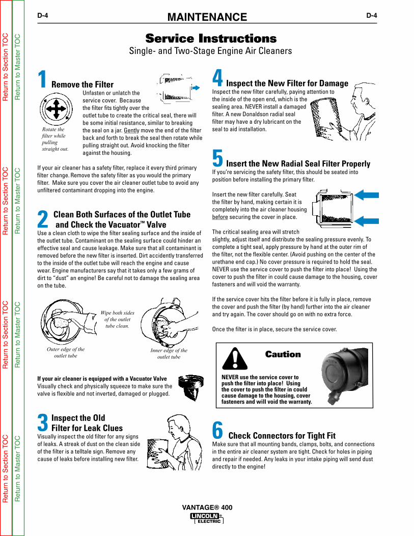
MAINTENANCED-4 D-4
VANTAGE® 400
Ret
urn
to S
ectio
n TO
CR
etur
n to
Sec
tion
TOC
Ret
urn
to S
ectio
n TO
CR
etur
n to
Sec
tion
TOC
Ret
urn
to M
aste
r TO
CR
etur
n to
Mas
ter
TOC
Ret
urn
to M
aste
r TO
CR
etur
n to
Mas
ter
TOC
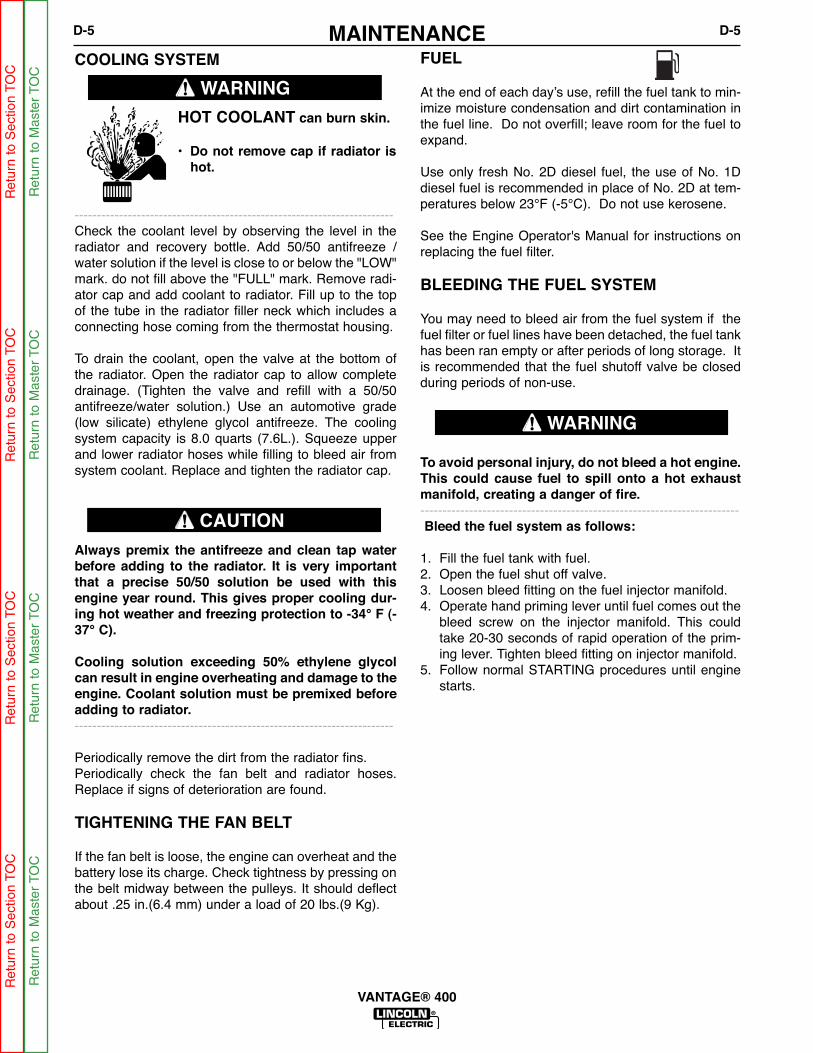
MAINTENANCED-5 D-5
VANTAGE® 400
COOLING SYSTEM
HOT COOLANT can burn skin.
• Do not remove cap if radiator ishot.
------------------------------------------------------------------------Check the coolant level by observing the level in theradiator and recovery bottle. Add 50/50 antifreeze /water solution if the level is close to or below the "LOW"mark. do not fill above the "FULL" mark. Remove radi-ator cap and add coolant to radiator. Fill up to the topof the tube in the radiator filler neck which includes aconnecting hose coming from the thermostat housing.
To drain the coolant, open the valve at the bottom ofthe radiator. Open the radiator cap to allow completedrainage. (Tighten the valve and refill with a 50/50antifreeze/water solution.) Use an automotive grade(low silicate) ethylene glycol antifreeze. The coolingsystem capacity is 8.0 quarts (7.6L.). Squeeze upperand lower radiator hoses while filling to bleed air fromsystem coolant. Replace and tighten the radiator cap.
Always premix the antifreeze and clean tap waterbefore adding to the radiator. It is very importantthat a precise 50/50 solution be used with thisengine year round. This gives proper cooling dur-ing hot weather and freezing protection to -34° F (-37° C).
Cooling solution exceeding 50% ethylene glycolcan result in engine overheating and damage to theengine. Coolant solution must be premixed beforeadding to radiator.------------------------------------------------------------------------
Periodically remove the dirt from the radiator fins.Periodically check the fan belt and radiator hoses.Replace if signs of deterioration are found.
TIGHTENING THE FAN BELT
If the fan belt is loose, the engine can overheat and thebattery lose its charge. Check tightness by pressing onthe belt midway between the pulleys. It should deflectabout .25 in.(6.4 mm) under a load of 20 lbs.(9 Kg).
FUEL
At the end of each day’s use, refill the fuel tank to min-imize moisture condensation and dirt contamination inthe fuel line. Do not overfill; leave room for the fuel toexpand.
Use only fresh No. 2D diesel fuel, the use of No. 1Ddiesel fuel is recommended in place of No. 2D at tem-peratures below 23°F (-5°C). Do not use kerosene.
See the Engine Operator's Manual for instructions onreplacing the fuel filter.
BLEEDING THE FUEL SYSTEM
You may need to bleed air from the fuel system if thefuel filter or fuel lines have been detached, the fuel tankhas been ran empty or after periods of long storage. Itis recommended that the fuel shutoff valve be closedduring periods of non-use.
To avoid personal injury, do not bleed a hot engine.This could cause fuel to spill onto a hot exhaustmanifold, creating a danger of fire.------------------------------------------------------------------------Bleed the fuel system as follows:
1. Fill the fuel tank with fuel.2. Open the fuel shut off valve.3. Loosen bleed fitting on the fuel injector manifold.4. Operate hand priming lever until fuel comes out the
bleed screw on the injector manifold. This couldtake 20-30 seconds of rapid operation of the prim-ing lever. Tighten bleed fitting on injector manifold.
5. Follow normal STARTING procedures until enginestarts.
WARNING
CAUTION
WARNING
Ret
urn
to S
ectio
n TO
CR
etur
n to
Sec
tion
TOC
Ret
urn
to S
ectio
n TO
CR
etur
n to
Sec
tion
TOC
Ret
urn
to M
aste
r TO
CR
etur
n to
Mas
ter
TOC
Ret
urn
to M
aste
r TO
CR
etur
n to
Mas
ter
TOC

MAINTENANCED-6 D-6
VANTAGE® 400
FUEL FILTER1. Check the fuel filter and fuel pre-filter for water accu-
mulation or sediment.2. Replace the fuel filter if it is found with excessive
water accumulation or sediment. Empty fuel pre-filter.
ENGINE ADJUSTMENT
Adjustments to the engine are to be made only by aLincoln Service Center or an authorized Field ServiceShop.
BATTERY MAINTENANCETo access the battery, remove the battery tray from thefront of the machine with 3/8” nut driver or flat headscrew driver. Pull the tray out of machine far enough todisconnect the negative and then positive batterycables. The tray can then be tilted and lifted to removethe entire tray and battery from the machine for easyservice.
GASES FROM BATTERY can explode.• Keep sparks, flame and cigarettes
away from battery.
To prevent EXPLOSION when:• INSTALLING A NEW BATTERY —
disconnect negative cable from oldbattery first and connect to new bat-tery last.
• CONNECTING A BATTERY CHARGER — removebattery from welder by disconnecting negativecable first, then positive cable and batteryclamp. When reinstalling, connect
negative cable last. Keep well ventilated.
• USING A BOOSTER — connect positive lead tobattery first then connect negative lead to nega-tive battery lead at engine foot.
BATTERY ACID can burn eyes and skin.• Wear gloves and eye protection and
be careful when working near bat-tery.
• Follow instructions printed on bat-tery.
OVERSPEED IS HAZARDOUSThe maximum allowable high idle speed for thismachine is 1890 RPM, no load. Do NOT tamper withgovernor components or setting or make any otheradjustments to increase the maximum speed.Severe personal injury and damage to the machinecan result if operated at speeds above maximum.
CLEANING THE BATTERYKeep the battery clean by wiping it with a damp clothwhen dirty. If the terminals appear corroded, discon-nect the battery cables and wash the terminals with anammonia solution or a solution of 1/4 pound (0.1113kg) of baking soda and 1 quart (0.9461L) of water. Besure the battery vent plugs (if equipped) are tight sothat none of the solution enters the cells.After cleaning, flush the outside of the battery, the bat-tery compartment, and surrounding areas with clearwater. Coat the battery terminals lightly with petroleumjelly or a non-conductive grease to retard corrosion.Keep the battery clean and dry. Moisture accumulationon the battery can lead to more rapid discharge andearly battery failure.
CHECKING THE ELECTROLYTE LEVEL
If battery cells are low, fill them to the neck of the fillerhole with distilled water and recharge. If one cell is low,check for leaks.
CHARGING THE BATTERYWhen you charge, jump, replace, or otherwise connectbattery cables to the battery, be sure the polarity is cor-rect. Improper polarity can damage the charging cir-cuit. The VANTAGE® 400 positive (+) battery terminalhas a red terminal cover.
If you need to charge the battery with an externalcharger, disconnect the negative cable first, then thepositive cable before you attach the charger leads.After the battery is charged, reconnect the positive bat-tery cable first and the negative cable last. Failure to doso can result in damage to the internal charger com-ponents.Follow the instructions of the battery charger manufac-turer for proper charger settings and charging time.
SERVICING OPTIONAL SPARKARRESTORClean every 100 hours.
WARNING
WARNING• MUFFLER MAY BE HOT
• ALLOW ENGINE TO COOL BEFORE INSTALLINGTHE SPARK ARRESTER!
• DO NOT OPERATE ENGINE WHILE INSTALLINGTHE SPARK ARRESTER!
Ret
urn
to S
ectio
n TO
CR
etur
n to
Sec
tion
TOC
Ret
urn
to S
ectio
n TO
CR
etur
n to
Sec
tion
TOC
Ret
urn
to M
aste
r TO
CR
etur
n to
Mas
ter
TOC
Ret
urn
to M
aste
r TO
CR
etur
n to
Mas
ter
TOC

MAINTENANCED-7 D-7
VANTAGE® 400
WELDER / GENERATORMAINTENANCE
STORAGE: Store in clean, dry protected areas.
CLEANING: Blow out the generator and controls peri-odically with low pressure air. Do this at least once aweek in particularly dirty areas.
BRUSH REMOVAL AND REPLACEMENT: It’s normalfor the brushes and slip rings to wear and darkenslightly. Inspect the brushes when a generator over-haul is necessary.
• Do not attempt to polish slip rings while theengine is running.
GFCI RECEPTACLE TESTING AND RESET-TING PROCEDURE
The GFCI receptacle should be properly tested at leastonce every month or whenever it is tripped. To proper-ly test and reset the GFCI receptacle:
• If the receptacle has tripped, first carefully removeany load and check it for damage.
• If the equipment has been shut down, it must berestarted.
• The equipment needs to be operating at high idlespeed and any necessary adjustments made on thecontrol panel so that the equipment is providing atleast 80 volts to the receptacle input terminals.
• The circuit breaker for this receptacle must not betripped. Reset if necessary.
• Push the "Reset" button located on the GFCI recep-tacle. This will assure normal GFCI operation.
• Plug a night-light (with an "ON/OFF" switch) or otherproduct (such as a lamp) into the GFCI receptacleand turn the product "ON".
• Push the "Test" button located on the GFCI recepta-cle. The night-light or other product should go "OFF".
• Push the "Reset" button, again. The light or otherproduct should go "ON" again.
If the light or other product remains "ON" when the"Test" button is pushed, the GFCI is not working prop-erly or has been incorrectly installed (miswired). If yourGFCI is not working properly, contact a qualified, certi-fied electrician who can assess the situation, rewire theGFCI if necessary or replace the device.
WARNING
• Service and Repair should only be performed byLincoln Electric Factory Trained Personnel.Unauthorized repairs performed on this equip-ment may result in danger to the technician andmachine operator and will invalidate your factorywarranty. For your safety and to avoid ElectricalShock, please observe all safety notes and pre-cautions.
CAUTION
Ret
urn
to S
ectio
n TO
CR
etur
n to
Sec
tion
TOC
Ret
urn
to S
ectio
n TO
CR
etur
n to
Sec
tion
TOC
Ret
urn
to M
aste
r TO
CR
etur
n to
Mas
ter
TOC
Ret
urn
to M
aste
r TO
CR
etur
n to
Mas
ter
TOC

MAINTENANCED-8 D-8
VANTAGE® 400
1. Case Front & Control Panel Assembly2. Output Panel Assembly3. Power Module Panel Assembly4. Generator & Rotor Assembly5. Base, Fuel Tank & Battery Assembly6. Engine Assembly7. Case Back & Radiator Assembly8. Case Cover
MAJOR COMPONENT LOCATION
88
44
22
11
55
66
77
33
Ret
urn
to S
ectio
n TO
CR
etur
n to
Sec
tion
TOC
Ret
urn
to S
ectio
n TO
CR
etur
n to
Sec
tion
TOC
Ret
urn
to M
aste
r TO
CR
etur
n to
Mas
ter
TOC
Ret
urn
to M
aste
r TO
CR
etur
n to
Mas
ter
TOC
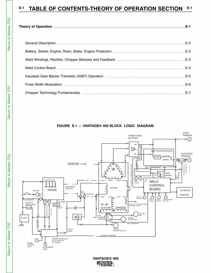
TABLE OF CONTENTS-THEORY OF OPERATION SECTIONE-1 E-1
VANTAGE® 400
FIGURE E.1 — VANTAGE® 400 BLOCK LOGIC DIAGRAM.
W
E
L
D
WI
N
D
I
N
G
30
AUXILIARY WINDINGS
10 + 30
ROTOR
+
REMOTE
AMPHENOL
ARC
CONTROL
OUTPUT
CONTROL
PROCESS/RANGE
SELECTOR
WELD
CONTROL
BOARD
THREE-PHASE
RECTIFIER
WORK
TERMINAL
ELECTRODE
TERMINAL
CHOPPER MODULE
IGBT
CHOKE
VOLTMETER
AMMETER
PWM
SIGNAL
VRD
VOLTAGE REDUCTION
VRD FEEDBACK
VRD
LIGHTS
R G
VRD
SWITCH
(OFF)
SHUNT
AUX. FEEDBACK
120VAC
RECEPTACLED (2)
AUX
CURRENT
TORROID
42 VAC TO 14 PIN AMPHENOL
FOR WIRE FEEDER
240 VAC
30
240VAC
RECEPTACLE
LOW IDLE COMMAND
FEEDBACK
CURRENT
IDLE
V.R.D
.
PO
WE
R T
O C
ON
TR
OL
BO
AR
D
PO
WE
R T
O
VR
D
80 VDC
VO
LT
FE
ED
BA
CK
+
-
ENGINE
GLOW PLUGS
MECHANICAL
ROTATION
STARTER
ALTERNATOR
BATTERY
OIL PRESS
TEMP
ROTOR
FLASH
ENGINE PROTECTION
IDLER CONTROL
P.C. BOARD
STATOR
SLIP
RINGS
+ -
RUN/STOP
SWITCH (RUN) ENGINE
SENSORS
ENGINE
TROUBLE
LIGHT
Y
ALT
SOL SOL
ALT
FL
AS
H
SHUTDOWN
IDLER
+
-
Y
ALTERNATOR
LIGHT
Theory of Operation . . . . . . . . . . . . . . . . . . . . . . . . . . . . . . . . . . . . . . . . . . . . . . . . . . . . . . . . . . . . . . . . . . . . .E-1
General Description . . . . . . . . . . . . . . . . . . . . . . . . . . . . . . . . . . . . . . . . . . . . . . . . . . . . . . . . . . . . . . . . . . .E-2
Battery, Starter, Engine, Rotor, Stator, Engine Protection . . . . . . . . . . . . . . . . . . . . . . . . . . . . . . . . . . . . . .E-2
Weld Windings, Rectifier, Chopper Modules and Feedback . . . . . . . . . . . . . . . . . . . . . . . . . . . . . . . . . . . .E-3
Weld Control Board . . . . . . . . . . . . . . . . . . . . . . . . . . . . . . . . . . . . . . . . . . . . . . . . . . . . . . . . . . . . . . . . . . .E-4
Insulated Gate Bipolar Transistor (IGBT) Operation . . . . . . . . . . . . . . . . . . . . . . . . . . . . . . . . . . . . . . . . . .E-5
Pulse Width Modulation . . . . . . . . . . . . . . . . . . . . . . . . . . . . . . . . . . . . . . . . . . . . . . . . . . . . . . . . . . . . . . . .E-6
Chopper Technology Fundamentals . . . . . . . . . . . . . . . . . . . . . . . . . . . . . . . . . . . . . . . . . . . . . . . . . . . . . .E-7
Ret
urn
to M
aste
r TO
CR
etur
n to
Mas
ter
TOC
Ret
urn
to M
aste
r TO
CR
etur
n to
Mas
ter
TOC
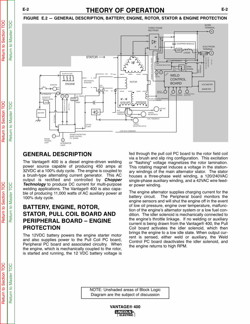
THEORY OF OPERATIONE-2 E-2
VANTAGE® 400
FIGURE E.2 — GENERAL DESCRIPTION, BATTERY, ENGINE, ROTOR, STATOR & ENGINE PROTECTION
W
E
L
D
WI
N
D
I
N
G
30
AUXILIARY WINDINGS
10 + 30
ROTOR
+
REMOTE
AMPHENOL
ARC
CONTROL
OUTPUT
CONTROL
PROCESS/RANGE
SELECTOR
WELD
CONTROL
BOARD
THREE-PHASE
RECTIFIER
WORK
TERMINAL
ELECTRODE
TERMINAL
CHOPPER MODULE
IGBT
CHOKE
VOLTMETER
AMMETER
PWM
SIGNAL
VRD
VOLTAGE REDUCTION
VRD FEEDBACK
VRD
LIGHTS
R G
VRD
SWITCH
(OFF)
SHUNT
AUX. FEEDBACK
120VAC
RECEPTACLED (2)
AUX
CURRENT
TORROID
42 VAC TO 14 PIN AMPHENOL
FOR WIRE FEEDER
240 VAC
30
240VAC
RECEPTACLE
LOW IDLE COMMAND
FEEDBACK
CURRENT
IDLE
V.R.D
.
PO
WE
R T
O C
ON
TR
OL
BO
AR
D
PO
WE
R T
O
VR
D
80 VDC
VO
LT
FE
ED
BA
CK
+
-
ENGINE
GLOW PLUGS
MECHANICAL
ROTATION
STARTER
ALTERNATOR
BATTERY
OIL PRESS
TEMP
ROTOR
FLASH
ENGINE PROTECTION
IDLER CONTROL
P.C. BOARD
STATOR
SLIP
RINGS
+ -
RUN/STOP
SWITCH (RUN) ENGINE
SENSORS
ENGINE
TROUBLE
LIGHT
Y
ALT
SOL SOL
ALT
FL
AS
H
SHUTDOWN
IDLER
+
-
Y
ALTERNATOR
LIGHT
NOTE: Unshaded areas of Block LogicDiagram are the subject of discussion
GENERAL DESCRIPTIONThe Vantage® 400 is a diesel engine-driven weldingpower source capable of producing 450 amps at32VDC at a 100% duty cycle. The engine is coupled toa brush-type alternating current generator. This ACoutput is rectified and controlled by ChopperTechnology to produce DC current for multi-purposewelding applications. The Vantage® 400 is also capa-ble of producing 11,000 watts of AC auxiliary power at100% duty cycle.
BATTERY, ENGINE, ROTOR, STATOR, PULL COIL BOARD ANDPERIPHERAL BOARD – ENGINEPROTECTIONThe 12VDC battery powers the engine starter motorand also supplies power to the Pull Coil PC board,Peripheral PC board and associated circuitry. Whenthe engine, which is mechanically coupled to the rotor,is started and running, the 12 VDC battery voltage is
fed through the pull coil PC board to the rotor field coilvia a brush and slip ring configuration. This excitationor "flashing" voltage magnetizes the rotor lamination.This rotating magnet induces a voltage in the station-ary windings of the main alternator stator. The statorhouses a three-phase weld winding, a 120/240VACsingle-phase auxiliary winding, and a 42VAC wire feed-er power winding.
The engine alternator supplies charging current for thebattery circuit. The Peripheral board monitors theengine sensors and will shut the engine off in the eventof low oil pressure, engine over temperature, malfunc-tion of the engine’s alternator system or a low fuel con-dition. The idler solenoid is mechanically connected tothe engine’s throttle linkage. If no welding or auxiliarycurrent is being drawn from the Vantage® 400, the PullCoil board activates the idler solenoid, which thenbrings the engine to a low idle state. When output cur-rent is sensed, either weld or auxiliary, the WeldControl PC board deactivates the idler solenoid, andthe engine returns to high RPM.
Ret
urn
to S
ectio
n TO
CR
etur
n to
Sec
tion
TOC
Ret
urn
to S
ectio
n TO
CR
etur
n to
Sec
tion
TOC
Ret
urn
to M
aste
r TO
CR
etur
n to
Mas
ter
TOC
Ret
urn
to M
aste
r TO
CR
etur
n to
Mas
ter
TOC
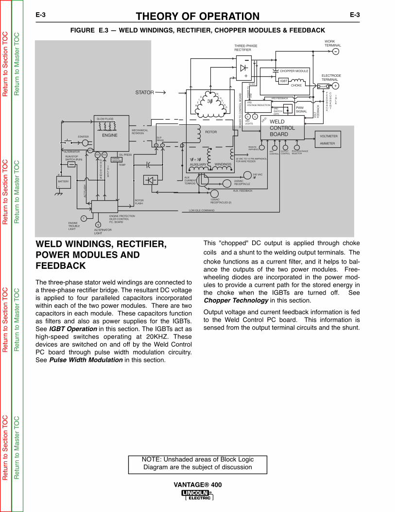
THEORY OF OPERATIONE-3 E-3
VANTAGE® 400
FIGURE E.3 — WELD WINDINGS, RECTIFIER, CHOPPER MODULES & FEEDBACK
W
E
L
D
WI
N
D
I
N
G
30
AUXILIARY WINDINGS
10 + 30
ROTOR
+
REMOTE
AMPHENOL
ARC
CONTROL
OUTPUT
CONTROL
PROCESS/RANGE
SELECTOR
WELD
CONTROL
BOARD
THREE-PHASE
RECTIFIER
WORK
TERMINAL
ELECTRODE
TERMINAL
CHOPPER MODULE
IGBT
CHOKE
VOLTMETER
AMMETER
PWM
SIGNAL
VRD
VOLTAGE REDUCTION
VRD FEEDBACK
VRD
LIGHTS
R G
VRD
SWITCH
(OFF)
SHUNT
AUX. FEEDBACK
120VAC
RECEPTACLED (2)
AUX
CURRENT
TORROID
42 VAC TO 14 PIN AMPHENOL
FOR WIRE FEEDER
240 VAC
30
240VAC
RECEPTACLE
LOW IDLE COMMAND
FEEDBACK
CURRENT
IDLE
V.R.D
.
PO
WE
R T
O C
ON
TR
OL B
OA
RD
PO
WE
R T
O
VR
D
80 VDC
VO
LT
FE
ED
BA
CK
+
-
ENGINE
GLOW PLUGS
MECHANICAL
ROTATION
STARTER
ALTERNATOR
BATTERY
OIL PRESS
TEMP
ROTOR
FLASH
ENGINE PROTECTION
IDLER CONTROL
P.C. BOARD
STATOR
SLIP
RINGS
+ -
RUN/STOP
SWITCH (RUN) ENGINE
SENSORS
ENGINE
TROUBLE
LIGHT
Y
ALT
SOL SOL
ALT
FLA
SH
SHUTDOWN
IDLER
+
-
Y
ALTERNATOR
LIGHT
NOTE: Unshaded areas of Block LogicDiagram are the subject of discussion
WELD WINDINGS, RECTIFIER,POWER MODULES ANDFEEDBACK
The three-phase stator weld windings are connected toa three-phase rectifier bridge. The resultant DC voltageis applied to four paralleled capacitors incorporatedwithin each of the two power modules. There are twocapacitors in each module. These capacitors functionas filters and also as power supplies for the IGBTs.See IGBT Operation in this section. The IGBTs act ashigh-speed switches operating at 20KHZ. Thesedevices are switched on and off by the Weld ControlPC board through pulse width modulation circuitry.See Pulse Width Modulation in this section.
This "chopped" DC output is applied through chokecoils and a shunt to the welding output terminals. Thechoke functions as a current filter, and it helps to bal-ance the outputs of the two power modules. Free-wheeling diodes are incorporated in the power mod-ules to provide a current path for the stored energy inthe choke when the IGBTs are turned off. SeeChopper Technology in this section.
Output voltage and current feedback information is fedto the Weld Control PC board. This information issensed from the output terminal circuits and the shunt.
Ret
urn
to S
ectio
n TO
CR
etur
n to
Sec
tion
TOC
Ret
urn
to S
ectio
n TO
CR
etur
n to
Sec
tion
TOC
Ret
urn
to M
aste
r TO
CR
etur
n to
Mas
ter
TOC
Ret
urn
to M
aste
r TO
CR
etur
n to
Mas
ter
TOC

THEORY OF OPERATIONE-4 E-4
VANTAGE® 400
FIGURE E.4 — WELD CONTROL BOARD
W
E
L
D
WI
N
D
I
N
G
30
AUXILIARY WINDINGS
10 + 30
ROTOR
+
REMOTE
AMPHENOL
ARC
CONTROL
OUTPUT
CONTROL
PROCESS/RANGE
SELECTOR
WELD
CONTROL
BOARD
THREE-PHASE
RECTIFIER
WORK
TERMINAL
ELECTRODE
TERMINAL
CHOPPER MODULE
IGBT
CHOKE
VOLTMETER
AMMETER
PWM
SIGNAL
VRD
VOLTAGE REDUCTION
VRD FEEDBACK
VRD
LIGHTS
R G
VRD
SWITCH
(OFF)
SHUNT
AUX. FEEDBACK
120VAC
RECEPTACLED (2)
AUX
CURRENT
TORROID
42 VAC TO 14 PIN AMPHENOL
FOR WIRE FEEDER
240 VAC
30
240VAC
RECEPTACLE
LOW IDLE COMMAND
FEEDBACK
CURRENT
IDLE
V.R.D
.
PO
WE
R T
O C
ON
TR
OL
BO
AR
D
PO
WE
R T
O
VR
D
80 VDC
VO
LT
FE
ED
BA
CK
+
-
ENGINE
GLOW PLUGS
MECHANICAL
ROTATION
STARTER
ALTERNATOR
BATTERY
OIL PRESS
TEMP
ROTOR
FLASH
ENGINE PROTECTION
IDLER CONTROL
P.C. BOARD
STATOR
SLIP
RINGS
+ -
RUN/STOP
SWITCH (RUN) ENGINE
SENSORS
ENGINE
TROUBLE
LIGHT
Y
ALT
SOL SOL
ALT
FL
AS
H
SHUTDOWN
IDLER
+
-
Y
ALTERNATOR
LIGHT
NOTE: Unshaded areas of Block LogicDiagram are the subject of discussion
WELD CONTROL BOARD
The 80 VDC derived from the filter capacitors on thePower Modules, supplies various regulated DC volt-ages to operate the Weld Control PC board circuitry. Italso supplies two regulated DC voltages to operate theIGBT driver circuitry on the two Power Modules.
The Weld Control PC board monitors the operator con-trols (arc control, output, and process/range selector).It compares these commands to the current and volt-age feedback information it receives from the shunt
and output terminal circuits. The circuitry on the WeldControl PC board determines how the output should becontrolled to optimize welding results, and it sends thecorrect PWM signals to the IGBT driver circuits. TheWeld Control PC board also commands the thermallight and the voltmeter and ammeter (some items maybe optional).
Ret
urn
to S
ectio
n TO
CR
etur
n to
Sec
tion
TOC
Ret
urn
to S
ectio
n TO
CR
etur
n to
Sec
tion
TOC
Ret
urn
to M
aste
r TO
CR
etur
n to
Mas
ter
TOC
Ret
urn
to M
aste
r TO
CR
etur
n to
Mas
ter
TOC
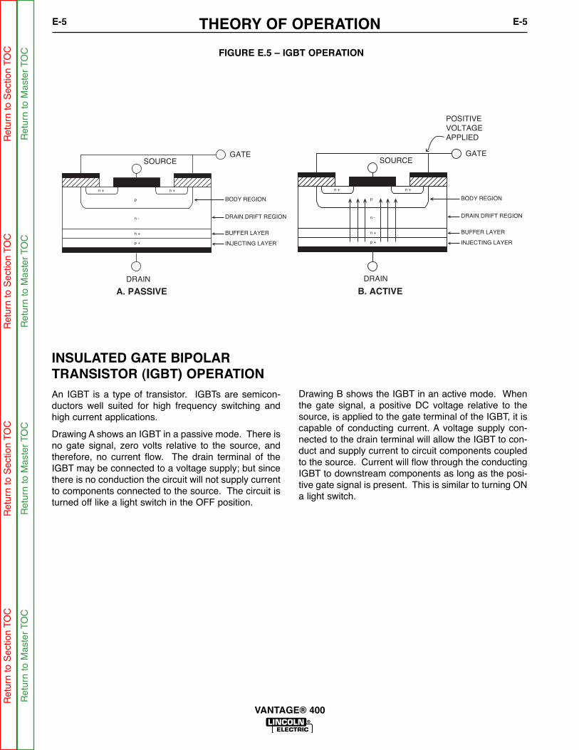
THEORY OF OPERATIONE-5 E-5
VANTAGE® 400
INSULATED GATE BIPOLAR TRANSISTOR (IGBT) OPERATION
An IGBT is a type of transistor. IGBTs are semicon-ductors well suited for high frequency switching andhigh current applications.
Drawing A shows an IGBT in a passive mode. There isno gate signal, zero volts relative to the source, andtherefore, no current flow. The drain terminal of theIGBT may be connected to a voltage supply; but sincethere is no conduction the circuit will not supply currentto components connected to the source. The circuit isturned off like a light switch in the OFF position.
Drawing B shows the IGBT in an active mode. Whenthe gate signal, a positive DC voltage relative to thesource, is applied to the gate terminal of the IGBT, it iscapable of conducting current. A voltage supply con-nected to the drain terminal will allow the IGBT to con-duct and supply current to circuit components coupledto the source. Current will flow through the conductingIGBT to downstream components as long as the posi-tive gate signal is present. This is similar to turning ONa light switch.
FIGURE E.5 – IGBT OPERATION
Ret
urn
to S
ectio
n TO
CR
etur
n to
Sec
tion
TOC
Ret
urn
to S
ectio
n TO
CR
etur
n to
Sec
tion
TOC
Ret
urn
to M
aste
r TO
CR
etur
n to
Mas
ter
TOC
Ret
urn
to M
aste
r TO
CR
etur
n to
Mas
ter
TOC

THEORY OF OPERATIONE-6 E-6
VANTAGE® 400
PULSE WIDTH MODULATION
The term PULSE WIDTH MODULATION is used todescribe how much time is devoted to conduction in thecycle. Changing the pulse width is known as MODU-LATION. Pulse Width Modulation (PWM) is the varyingof the pulse width over the allowed range of a cycle toaffect the output of the machine.
MINIMUM OUTPUT
By controlling the duration of the gate signal, the IGBTis turned on and off for different durations during acycle. The top drawing shows the minimum output sig-nal possible over a 50-microsecond time period.
The positive portion of the signal represents one IGBTgroup conducting for 2 microsecond. The dwell time (offtime) is 48 microseconds. Since only 2 microseconds ofthe 50-microsecond time period is devoted to conduct-ing, the output power is minimized.
MAXIMUM OUTPUT
By holding the gate signals on for 48 microseconds andallowing only 2 microseconds of dwell time (off time)during the 50-microsecond cycle, the output is maxi-mized. The darkened area under the top curve can becompared to the area under the bottom curve. Themore darkened area under the curve, the more poweris present.
FIGURE E.6 – TYPICAL IGBT OUTPUTS
MINIMUM OUTPUT
MAXIMUM OUTPUT
50
50 sec
sec
sec 48 sec(Dwell or Off Time)
(Dwell or Off Time)
48 sec
2
Ret
urn
to S
ectio
n TO
CR
etur
n to
Sec
tion
TOC
Ret
urn
to S
ectio
n TO
CR
etur
n to
Sec
tion
TOC
Ret
urn
to M
aste
r TO
CR
etur
n to
Mas
ter
TOC
Ret
urn
to M
aste
r TO
CR
etur
n to
Mas
ter
TOC

THEORY OF OPERATIONE-7 E-7
VANTAGE® 400
CHOPPER TECHNOLOGY FUNDAMENTALS
The new era of welding machines such as theVantage® 500, employ a technology whereby a DCsource is turned on and off (chopped up) at high speed,then smoothed through an inductor to control an arc.
Hence the name “Chopper.” The biggest advantage®of chopper technology is the high-speed control of thearc, similar to the inverter machines. A block diagramfor this is as follows:
In this system, the engine drives a three-phase alter-nator, which generates power that is rectified and filtered to produce about 75VDC. The current isapplied through a solid state switch to an inductor. By
turning the switch on and off, current in the inductorand the arc can be controlled. The following diagramdepicts the current flow in the system when the switchis open and closed.
When the switch is closed, current is applied throughthe inductor to the arc. When the switch opens, currentstored in the inductor sustains flow in the arc andthrough the diode. The repetition rate of switch closureis 20Khz, which allows ultra-fast control of the arc. By
varying the ratio of on time versus off time of the switch(Duty Cycle), the current applied to the arc is con-trolled. This is the basis for Chopper Technology:Controlling the switch in such a way as to producesuperior welding.
EXTERNALDC SOURCE
INDUCTORAND DIODE ARC
ARCCONTROL
SOLID STATESWITCH
INDUCTOR
SWITCH
DIODEARC
CURRENT WITH SWITCH OPEN
CURRENT WITH SWITCH CLOSED
70-80VDC
Ret
urn
to S
ectio
n TO
CR
etur
n to
Sec
tion
TOC
Ret
urn
to S
ectio
n TO
CR
etur
n to
Sec
tion
TOC
Ret
urn
to M
aste
r TO
CR
etur
n to
Mas
ter
TOC
Ret
urn
to M
aste
r TO
CR
etur
n to
Mas
ter
TOC

NOTESE-8 E-8
VANTAGE® 400
Ret
urn
to S
ectio
n TO
CR
etur
n to
Sec
tion
TOC
Ret
urn
to S
ectio
n TO
CR
etur
n to
Sec
tion
TOC
Ret
urn
to M
aste
r TO
CR
etur
n to
Mas
ter
TOC
Ret
urn
to M
aste
r TO
CR
etur
n to
Mas
ter
TOC
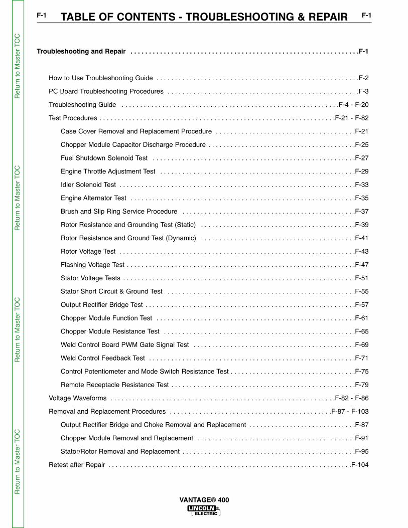
TABLE OF CONTENTS - TROUBLESHOOTING & REPAIRF-1 F-1
VANTAGE® 400
Troubleshooting and Repair . . . . . . . . . . . . . . . . . . . . . . . . . . . . . . . . . . . . . . . . . . . . . . . . . . . . . . . . . . . . . .F-1
How to Use Troubleshooting Guide . . . . . . . . . . . . . . . . . . . . . . . . . . . . . . . . . . . . . . . . . . . . . . . . . . . . . . .F-2
PC Board Troubleshooting Procedures . . . . . . . . . . . . . . . . . . . . . . . . . . . . . . . . . . . . . . . . . . . . . . . . . . . .F-3
Troubleshooting Guide . . . . . . . . . . . . . . . . . . . . . . . . . . . . . . . . . . . . . . . . . . . . . . . . . . . . . . . . . . .F-4 - F-20
Test Procedures . . . . . . . . . . . . . . . . . . . . . . . . . . . . . . . . . . . . . . . . . . . . . . . . . . . . . . . . . . . . . . . .F-21 - F-82
Case Cover Removal and Replacement Procedure . . . . . . . . . . . . . . . . . . . . . . . . . . . . . . . . . . . . . .F-21
Chopper Module Capacitor Discharge Procedure . . . . . . . . . . . . . . . . . . . . . . . . . . . . . . . . . . . . . . . .F-25
Fuel Shutdown Solenoid Test . . . . . . . . . . . . . . . . . . . . . . . . . . . . . . . . . . . . . . . . . . . . . . . . . . . . . . .F-27
Engine Throttle Adjustment Test . . . . . . . . . . . . . . . . . . . . . . . . . . . . . . . . . . . . . . . . . . . . . . . . . . . . .F-29
Idler Solenoid Test . . . . . . . . . . . . . . . . . . . . . . . . . . . . . . . . . . . . . . . . . . . . . . . . . . . . . . . . . . . . . . . .F-33
Engine Alternator Test . . . . . . . . . . . . . . . . . . . . . . . . . . . . . . . . . . . . . . . . . . . . . . . . . . . . . . . . . . . . .F-35
Brush and Slip Ring Service Procedure . . . . . . . . . . . . . . . . . . . . . . . . . . . . . . . . . . . . . . . . . . . . . . .F-37
Rotor Resistance and Grounding Test (Static) . . . . . . . . . . . . . . . . . . . . . . . . . . . . . . . . . . . . . . . . . .F-39
Rotor Resistance and Ground Test (Dynamic) . . . . . . . . . . . . . . . . . . . . . . . . . . . . . . . . . . . . . . . . . .F-41
Rotor Voltage Test . . . . . . . . . . . . . . . . . . . . . . . . . . . . . . . . . . . . . . . . . . . . . . . . . . . . . . . . . . . . . . . .F-43
Flashing Voltage Test . . . . . . . . . . . . . . . . . . . . . . . . . . . . . . . . . . . . . . . . . . . . . . . . . . . . . . . . . . . . . .F-47
Stator Voltage Tests . . . . . . . . . . . . . . . . . . . . . . . . . . . . . . . . . . . . . . . . . . . . . . . . . . . . . . . . . . . . . . .F-51
Stator Short Circuit & Ground Test . . . . . . . . . . . . . . . . . . . . . . . . . . . . . . . . . . . . . . . . . . . . . . . . . . .F-55
Output Rectifier Bridge Test . . . . . . . . . . . . . . . . . . . . . . . . . . . . . . . . . . . . . . . . . . . . . . . . . . . . . . . . .F-57
Chopper Module Function Test . . . . . . . . . . . . . . . . . . . . . . . . . . . . . . . . . . . . . . . . . . . . . . . . . . . . . .F-61
Chopper Module Resistance Test . . . . . . . . . . . . . . . . . . . . . . . . . . . . . . . . . . . . . . . . . . . . . . . . . . . .F-65
Weld Control Board PWM Gate Signal Test . . . . . . . . . . . . . . . . . . . . . . . . . . . . . . . . . . . . . . . . . . . .F-69
Weld Control Feedback Test . . . . . . . . . . . . . . . . . . . . . . . . . . . . . . . . . . . . . . . . . . . . . . . . . . . . . . . .F-71
Control Potentiometer and Mode Switch Resistance Test . . . . . . . . . . . . . . . . . . . . . . . . . . . . . . . . . .F-75
Remote Receptacle Resistance Test . . . . . . . . . . . . . . . . . . . . . . . . . . . . . . . . . . . . . . . . . . . . . . . . . .F-79
Voltage Waveforms . . . . . . . . . . . . . . . . . . . . . . . . . . . . . . . . . . . . . . . . . . . . . . . . . . . . . . . . . . . . .F-82 - F-86
Removal and Replacement Procedures . . . . . . . . . . . . . . . . . . . . . . . . . . . . . . . . . . . . . . . . . . . .F-87 - F-103
Output Rectifier Bridge and Choke Removal and Replacement . . . . . . . . . . . . . . . . . . . . . . . . . . . . .F-87
Chopper Module Removal and Replacement . . . . . . . . . . . . . . . . . . . . . . . . . . . . . . . . . . . . . . . . . . .F-91
Stator/Rotor Removal and Replacement . . . . . . . . . . . . . . . . . . . . . . . . . . . . . . . . . . . . . . . . . . . . . . .F-95
Retest after Repair . . . . . . . . . . . . . . . . . . . . . . . . . . . . . . . . . . . . . . . . . . . . . . . . . . . . . . . . . . . . . . . . . .F-104
Ret
urn
to M
aste
r TO
CR
etur
n to
Mas
ter
TOC
Ret
urn
to M
aste
r TO
CR
etur
n to
Mas
ter
TOC

TROUBLESHOOTING & REPAIRF-2 F-2
VANTAGE® 400
This Troubleshooting Guide is provided tohelp you locate and repair possible machinemalfunctions. Simply follow the three-stepprocedure listed below.
Step 1. LOCATE PROBLEM (SYMPTOM).
Look under the column labeled “PROBLEM(SYMPTOMS)”. This column describes pos-sible symptoms that the machine may exhib-it. Find the listing that best describes thesymptom that the machine is exhibiting.Symptoms are grouped into the followingcategories: output problems, function prob-lems, wire feeding problems, and weldingproblems.
Step 2. PERFORM EXTERNAL TESTS.
The second column labeled “POSSIBLEAREAS OF MISADJUSTMENT(S)” lists theobvious external possibilities that may con-tribute to the machine symptom. Performthese tests/checks in the order listed. Ingeneral, these tests can be conducted with-out removing the case wrap-around cover.
Step 3. RECOMMENDED
COURSE OF ACTION
The last column labeled “RecommendedCourse of Action” lists the most likely com-ponents that may have failed in yourmachine. It also specifies the appropriatetest procedure to verify that the subject com-ponent is either good or bad. If there are anumber of possible components, check thecomponents in the order listed to eliminateone possibility at a time until you locate thecause of your problem.
All of the referenced test proceduresreferred to in the Troubleshooting Guide aredescribed in detail at the end of this chapter.Refer to the Troubleshooting and RepairTable of Contents to locate each specificTest Procedure. All of the specified testpoints, components, terminal strips, etc. canbe found on the referenced electrical wiringdiagrams and schematics. Refer to theElectrical Diagrams Section Table ofContents to locate the appropriate diagram.
HOW TO USE TROUBLESHOOTING GUIDE
Service and Repair should only be performed by Lincoln Electric Factory TrainedPersonnel. Unauthorized repairs performed on this equipment may result in danger tothe technician and machine operator and will invalidate your factory warranty. For yoursafety and to avoid Electrical Shock, please observe all safety notes and precautionsdetailed throughout this manual.---------------------------------------------------------------------------------------------------------------------------
WARNING
CAUTION
If for any reason you do not understand the test procedures or are unable to perform thetests/repairs safely, contact the Lincoln Electric Service Department for technical troubleshootingassistance before you proceed. Call 1-888-935-3877.-----------------------------------------------------------------------------------------------------------------------------------
Ret
urn
to S
ectio
n TO
CR
etur
n to
Sec
tion
TOC
Ret
urn
to S
ectio
n TO
CR
etur
n to
Sec
tion
TOC
Ret
urn
to M
aste
r TO
CR
etur
n to
Mas
ter
TOC
Ret
urn
to M
aste
r TO
CR
etur
n to
Mas
ter
TOC

TROUBLESHOOTING & REPAIRF-3 F-3
VANTAGE® 400
Sometimes machine failures appear to be due to PCboard failures. These problems can sometimes betraced to poor electrical connections. To avoid prob-lems when troubleshooting and replacing PC boards,please use the following procedure:
1. Determine to the best of your technical abilitythat the PC board is the most likely componentcausing the failure symptom.
2. Check for loose connections at the PC boardto assure that the PC board is properlyconnected.
3. If the problem persists, replace the suspect PCboard using standard practices to avoid staticelectrical damage and electrical shock. Readthe warning inside the static resistant bag andperform the following procedures:
PC board can be damaged by static electricity.
- Remove your body’s staticcharge before opening the static-shielding bag. Wear an anti-staticwrist strap. For safety, use a 1Meg ohm resistive cord connectedto a grounded part of theequipment frame.
- If you don’t have a wrist strap,touch an un-painted, grounded,part of the equipment frame. Keeptouching the frame to preventstatic build-up. Be sure not totouch any electrically live parts atthe same time.
- Tools which come in contact with the PC board mustbe either conductive, anti-static or static-disipative.
ELECTRIC SHOCKcan kill.
• Have an electrician install andservice this equipment. Turn theinput power OFF at the fuse boxbefore working on equipment. Donot touch electrically hot parts.
- Remove the PC board from the static-shielding bagand place it directly into the equipment. Don’t set thePC board on or near paper, plastic or cloth whichcould have a static charge. If the PC board can’t beinstalled immediately, put it back in the static-shield-ing bag.
- If the PC board uses protective shorting jumpers,don’t remove them until installation is complete.
- If you return a PC board to The Lincoln ElectricCompany for credit, it must be in the static-shieldingbag. This will prevent further damage and allow prop-er failure analysis.
4. Test the machine to determine if the failuresymptom has been corrected by thereplacement PC board.
NOTE: It is desirable to have a spare (known good)PC board available for PC board troubleshooting.
NOTE: Allow the machine to heat up so that allelectrical components can reach their operatingtemperature.
5. Remove the replacement PC board andsubstitute it with the original PC board torecreate the original problem.
a. If the original problem does not reappear bysubstituting the original board, then the PCboard was not the problem. Continue to lookfor bad connections in the control wiringharness, junction blocks, and terminal strips.
b. If the original problem is recreated by thesubstitution of the original board, then the PCboard was the problem. Reinstall thereplacement PC board and test the machine.
6. Always indicate that this procedure wasfollowed when warranty reports are to besubmitted.
NOTE: Following this procedure and writing on thewarranty report, “INSTALLED AND SWITCHED PCBOARDS TO VERIFY PROBLEM,” will help avoiddenial of legitimate PC board warranty claims.
PC BOARD TROUBLESHOOTING PROCEDURES
ATTENTIONStatic-SensitiveDevicesHandle only atStatic-SafeWorkstations
WARNING
CAUTION
Ret
urn
to S
ectio
n TO
CR
etur
n to
Sec
tion
TOC
Ret
urn
to S
ectio
n TO
CR
etur
n to
Sec
tion
TOC
Ret
urn
to M
aste
r TO
CR
etur
n to
Mas
ter
TOC
Ret
urn
to M
aste
r TO
CR
etur
n to
Mas
ter
TOC

Observe Safety Guidelines detailed in the beginning of this manual.
If for any reason you do not understand the test procedures or are unable to perform the tests/repairs safely,contact the Lincoln Electric Service Department for technical troubleshooting assistance before you proceed.Call 1-888-935-3877.
CAUTION
TROUBLESHOOTING & REPAIRF-4 F-4
VANTAGE® 400
PROBLEMS(SYMPTOMS)
POSSIBLE AREAS OFMISADJUSTMENT(S)
RECOMMENDEDCOURSE OF ACTION
OUTPUT PROBLEMS
Major mechanical or electricaldamage is evident.
1. Contact your local LincolnAuthorized Field ServiceFacility.
1. Contact the Lincoln ElectricService Department at 1-888-935-3877.
No welding output or auxiliarypower. The engine operates nor-mally.
Check for loose or faulty connec-tions in the auxiliary circuit to theoutput receptacles, and/or theweld circuit to the output terminals.SEE WIRING DIAGRAM.
Check the brushes for wear adproper contact to the rotor sliprings.
Check the brushes for wear andproper contact to the rotor sliprings
Perform the Brush and Slip Ring
Service Procedure.
Check for flashing voltage at sliprings (3-5 Volts [email protected] amp untilgenerator builds up, then 160Volts) See FLASHING VOLTAGE
TEST.
Check Field rectifier and capacitor.
Perform the Rotor Voltage Test.
Perform the Stator Voltage Test.
Ret
urn
to S
ectio
n TO
CR
etur
n to
Sec
tion
TOC
Ret
urn
to S
ectio
n TO
CR
etur
n to
Sec
tion
TOC
Ret
urn
to M
aste
r TO
CR
etur
n to
Mas
ter
TOC
Ret
urn
to M
aste
r TO
CR
etur
n to
Mas
ter
TOC
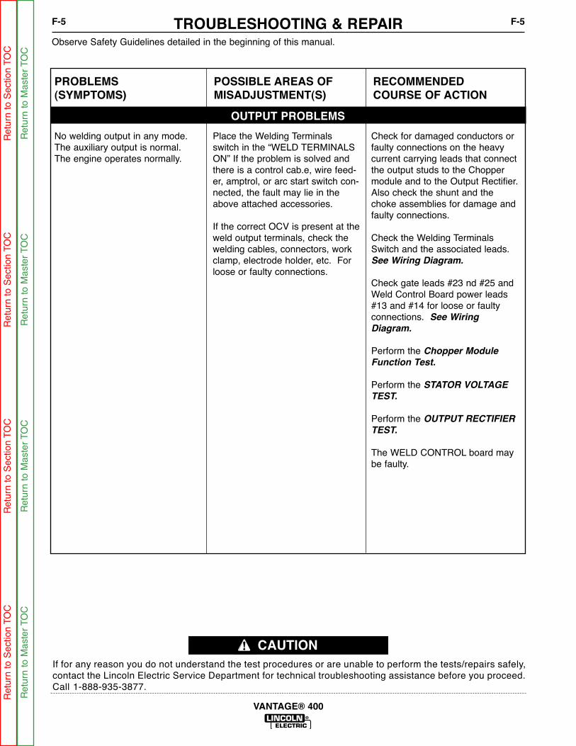
Observe Safety Guidelines detailed in the beginning of this manual.
If for any reason you do not understand the test procedures or are unable to perform the tests/repairs safely,contact the Lincoln Electric Service Department for technical troubleshooting assistance before you proceed.Call 1-888-935-3877.
CAUTION
TROUBLESHOOTING & REPAIRF-5 F-5
VANTAGE® 400
PROBLEMS(SYMPTOMS)
POSSIBLE AREAS OFMISADJUSTMENT(S)
RECOMMENDEDCOURSE OF ACTION
OUTPUT PROBLEMS
No welding output in any mode.The auxiliary output is normal.The engine operates normally.
Place the Welding Terminalsswitch in the “WELD TERMINALSON” If the problem is solved andthere is a control cab.e, wire feed-er, amptrol, or arc start switch con-nected, the fault may lie in theabove attached accessories.
If the correct OCV is present at theweld output terminals, check thewelding cables, connectors, workclamp, electrode holder, etc. Forloose or faulty connections.
Check for damaged conductors orfaulty connections on the heavycurrent carrying leads that connectthe output studs to the Choppermodule and to the Output Rectifier.Also check the shunt and thechoke assemblies for damage andfaulty connections.
Check the Welding TerminalsSwitch and the associated leads.See Wiring Diagram.
Check gate leads #23 nd #25 andWeld Control Board power leads#13 and #14 for loose or faultyconnections. See Wiring
Diagram.
Perform the Chopper Module
Function Test.
Perform the STATOR VOLTAGE
TEST.
Perform the OUTPUT RECTIFIER
TEST.
The WELD CONTROL board maybe faulty.
Ret
urn
to S
ectio
n TO
CR
etur
n to
Sec
tion
TOC
Ret
urn
to S
ectio
n TO
CR
etur
n to
Sec
tion
TOC
Ret
urn
to M
aste
r TO
CR
etur
n to
Mas
ter
TOC
Ret
urn
to M
aste
r TO
CR
etur
n to
Mas
ter
TOC
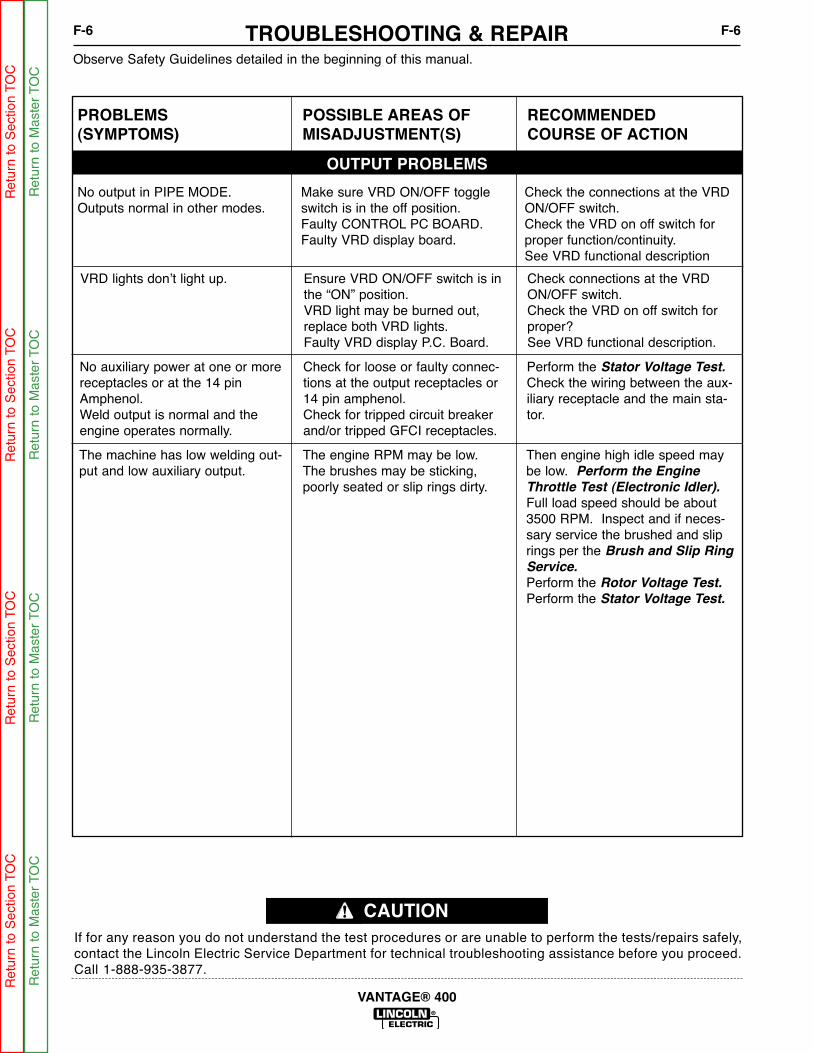
Observe Safety Guidelines detailed in the beginning of this manual.
If for any reason you do not understand the test procedures or are unable to perform the tests/repairs safely,contact the Lincoln Electric Service Department for technical troubleshooting assistance before you proceed.Call 1-888-935-3877.
CAUTION
TROUBLESHOOTING & REPAIRF-6 F-6
VANTAGE® 400
VRD lights don’t light up. Ensure VRD ON/OFF switch is inthe “ON” position.VRD light may be burned out,replace both VRD lights.Faulty VRD display P.C. Board.
Check connections at the VRDON/OFF switch.Check the VRD on off switch forproper?See VRD functional description.
PROBLEMS(SYMPTOMS)
POSSIBLE AREAS OFMISADJUSTMENT(S)
RECOMMENDEDCOURSE OF ACTION
OUTPUT PROBLEMS
No output in PIPE MODE. Outputs normal in other modes.
Make sure VRD ON/OFF toggleswitch is in the off position.Faulty CONTROL PC BOARD.Faulty VRD display board.
Check the connections at the VRDON/OFF switch.Check the VRD on off switch forproper function/continuity.See VRD functional description
No auxiliary power at one or morereceptacles or at the 14 pinAmphenol.Weld output is normal and theengine operates normally.
Check for loose or faulty connec-tions at the output receptacles or14 pin amphenol.Check for tripped circuit breakerand/or tripped GFCI receptacles.
Perform the Stator Voltage Test.
Check the wiring between the aux-iliary receptacle and the main sta-tor.
The machine has low welding out-put and low auxiliary output.
The engine RPM may be low.The brushes may be sticking,poorly seated or slip rings dirty.
Then engine high idle speed maybe low. Perform the Engine
Throttle Test (Electronic Idler).
Full load speed should be about3500 RPM. Inspect and if neces-sary service the brushed and sliprings per the Brush and Slip Ring
Service.
Perform the Rotor Voltage Test.
Perform the Stator Voltage Test.
Ret
urn
to S
ectio
n TO
CR
etur
n to
Sec
tion
TOC
Ret
urn
to S
ectio
n TO
CR
etur
n to
Sec
tion
TOC
Ret
urn
to M
aste
r TO
CR
etur
n to
Mas
ter
TOC
Ret
urn
to M
aste
r TO
CR
etur
n to
Mas
ter
TOC

The machine will weld but thewelding arc is “COLD”. Theengine runs normally and the aux-iliary power is normal.
Make sure the machine is properlyset for the electrode and processis being used. Check electrodesize, mode switch setting, andamps or voltage setting. If gas isused make sure of correct typeand gas flow.Make sure the process does notdemand more power than themachine can produce.If the current is correct try increas-ing the “ARC CONTROL” setting.Check for loose or faulty connec-tions at the weld output terminalsand welding cable connections.Check for good connectionsbetween the work cable and thework piece. The work cableshould be attached to clean metal,as close to the weld area as possi-ble. The work clamp must be ingood condition with good springtension.The weld cables may be too long,or too small diameter causingexcessive voltage drop.The weld cables may be coiled, orwrapped around metal racks orreels. This can cause excessiveinductance in the weld circuit. Trywelding with a short set of ade-quately sized weld cables.
The engine RPM may be too low.Perform the Engine Throttle
Adjustment Test.
Connect the machine to a resistiveload bank. Connect an accurateammeter and volt meter to the out-put of the machine. Connect atachometer, Hz meter or anothermethod to measure engine RPM.Place the mode switch in “CC-STICK, turn the output control tomaximum idle switch to “HIGH”terminal switch to “WELD TERMI-NALS ON”. Nothing else attachedor plugged into machine (No aux.,no control cables). Start themachine allow the engine to reachnormal operating temperature.Apply a load with the load bank.Load to 300 Amps, 32 Volts, 100%Duty Cycle.The engine should maintain 3350RPM.If the engine cannot maintain theRPM make sure there is a supplyof clean fresh fuel.Check the fuel filter and the air fil-ter.Replace any filter that is dirty; ordamaged.If this doesn’t help have theengine serviced.Compare the volt and amp read-ings displayed on the machinewith that of the load bank. If theseare significantly different, performthe WELD CONTROL FEED-
BACK TEST.
Observe Safety Guidelines detailed in the beginning of this manual.
If for any reason you do not understand the test procedures or are unable to perform the tests/repairs safely,contact the Lincoln Electric Service Department for technical troubleshooting assistance before you proceed.Call 1-888-935-3877.
CAUTION
TROUBLESHOOTING & REPAIRF-7 F-7
VANTAGE® 400
PROBLEMS(SYMPTOMS)
POSSIBLE AREAS OFMISADJUSTMENT(S)
RECOMMENDEDCOURSE OF ACTION
FUNCTION PROBLEMS
Ret
urn
to S
ectio
n TO
CR
etur
n to
Sec
tion
TOC
Ret
urn
to S
ectio
n TO
CR
etur
n to
Sec
tion
TOC
Ret
urn
to M
aste
r TO
CR
etur
n to
Mas
ter
TOC
Ret
urn
to M
aste
r TO
CR
etur
n to
Mas
ter
TOC
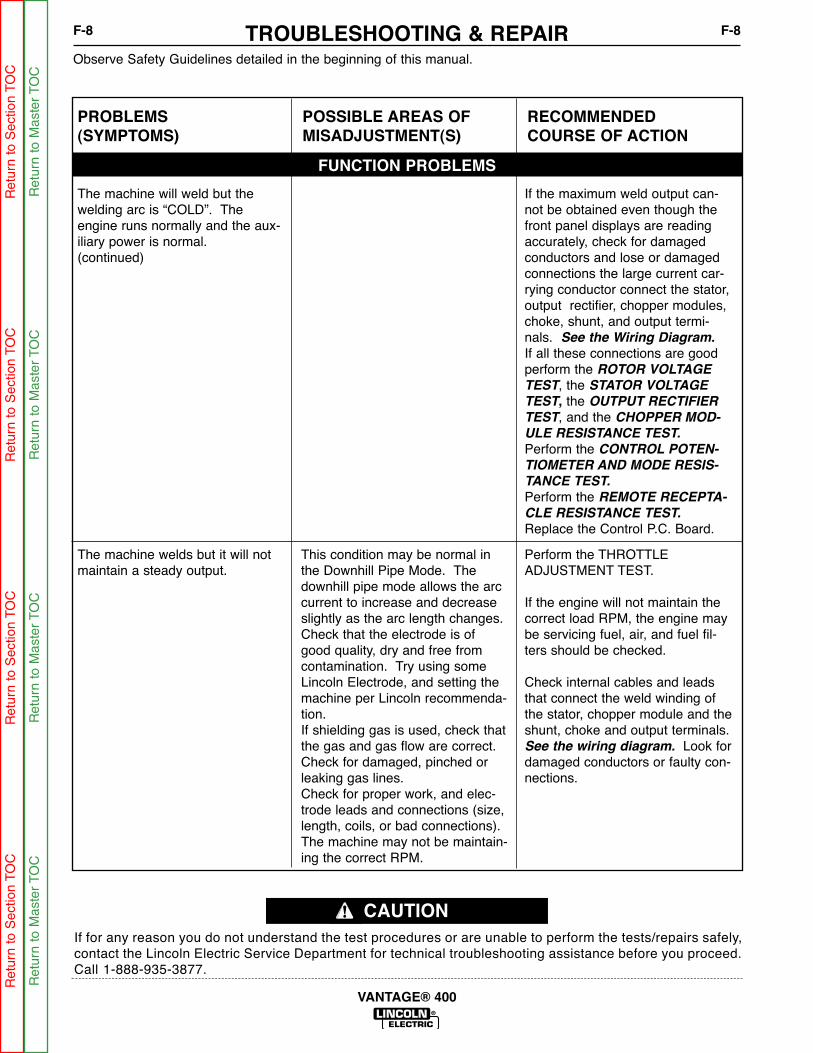
The machine welds but it will notmaintain a steady output.
This condition may be normal inthe Downhill Pipe Mode. Thedownhill pipe mode allows the arccurrent to increase and decreaseslightly as the arc length changes.Check that the electrode is ofgood quality, dry and free fromcontamination. Try using someLincoln Electrode, and setting themachine per Lincoln recommenda-tion.If shielding gas is used, check thatthe gas and gas flow are correct.Check for damaged, pinched orleaking gas lines.Check for proper work, and elec-trode leads and connections (size,length, coils, or bad connections).The machine may not be maintain-ing the correct RPM.
Perform the THROTTLEADJUSTMENT TEST.
If the engine will not maintain thecorrect load RPM, the engine maybe servicing fuel, air, and fuel fil-ters should be checked.
Check internal cables and leadsthat connect the weld winding ofthe stator, chopper module and theshunt, choke and output terminals.See the wiring diagram. Look fordamaged conductors or faulty con-nections.
Observe Safety Guidelines detailed in the beginning of this manual.
If for any reason you do not understand the test procedures or are unable to perform the tests/repairs safely,contact the Lincoln Electric Service Department for technical troubleshooting assistance before you proceed.Call 1-888-935-3877.
CAUTION
TROUBLESHOOTING & REPAIRF-8 F-8
VANTAGE® 400
PROBLEMS(SYMPTOMS)
POSSIBLE AREAS OFMISADJUSTMENT(S)
RECOMMENDEDCOURSE OF ACTION
FUNCTION PROBLEMS
The machine will weld but thewelding arc is “COLD”. Theengine runs normally and the aux-iliary power is normal.(continued)
If the maximum weld output can-not be obtained even though thefront panel displays are readingaccurately, check for damagedconductors and lose or damagedconnections the large current car-rying conductor connect the stator,output rectifier, chopper modules,choke, shunt, and output termi-nals. See the Wiring Diagram.
If all these connections are goodperform the ROTOR VOLTAGE
TEST, the STATOR VOLTAGE
TEST, the OUTPUT RECTIFIER
TEST, and the CHOPPER MOD-
ULE RESISTANCE TEST.
Perform the CONTROL POTEN-
TIOMETER AND MODE RESIS-
TANCE TEST.
Perform the REMOTE RECEPTA-
CLE RESISTANCE TEST.
Replace the Control P.C. Board.
Ret
urn
to S
ectio
n TO
CR
etur
n to
Sec
tion
TOC
Ret
urn
to S
ectio
n TO
CR
etur
n to
Sec
tion
TOC
Ret
urn
to M
aste
r TO
CR
etur
n to
Mas
ter
TOC
Ret
urn
to M
aste
r TO
CR
etur
n to
Mas
ter
TOC

Observe Safety Guidelines detailed in the beginning of this manual.
If for any reason you do not understand the test procedures or are unable to perform the tests/repairs safely,contact the Lincoln Electric Service Department for technical troubleshooting assistance before you proceed.Call 1-888-935-3877.
CAUTION
TROUBLESHOOTING & REPAIRF-9 F-9
VANTAGE® 400
PROBLEMS(SYMPTOMS)
POSSIBLE AREAS OFMISADJUSTMENT(S)
RECOMMENDEDCOURSE OF ACTION
ENGINE PROBLEMS
The machine welds but it will notmaintain a steady output.(continued)
There may be poor connections inthe control wiring at the weld con-trol P.C. Board, or the chopperboard. Pull each plug from theweld P.C. board and thoroughlyinspect the terminals in both theplugs and the P.C. Board recepta-cles. Make sure the connectionsare clean and the pins are proper-ly seated in the plastic plug hous-ing. Check for loose or damagedpins and faulty crimps.
Check for damaged wiring andpoor connections in the 13, 14,and the 23, and 25 leads, betweenthe chopper module and weld con-trol P.C. Board.
The output control or the arc con-trol potentiometer may be defec-tive or grounded. The modeswitch may also be faulty. Performthe POTENTIOMETER AND
MODE SWITCH RESISTANCE
TEST.
The Amphenol receptacles may becontaminated or defective.Perform the REMOTE RECEPTA-
CLE RESISTANCE TEST.
Replace the weld control P.C.Board.
Ret
urn
to S
ectio
n TO
CR
etur
n to
Sec
tion
TOC
Ret
urn
to S
ectio
n TO
CR
etur
n to
Sec
tion
TOC
Ret
urn
to M
aste
r TO
CR
etur
n to
Mas
ter
TOC
Ret
urn
to M
aste
r TO
CR
etur
n to
Mas
ter
TOC
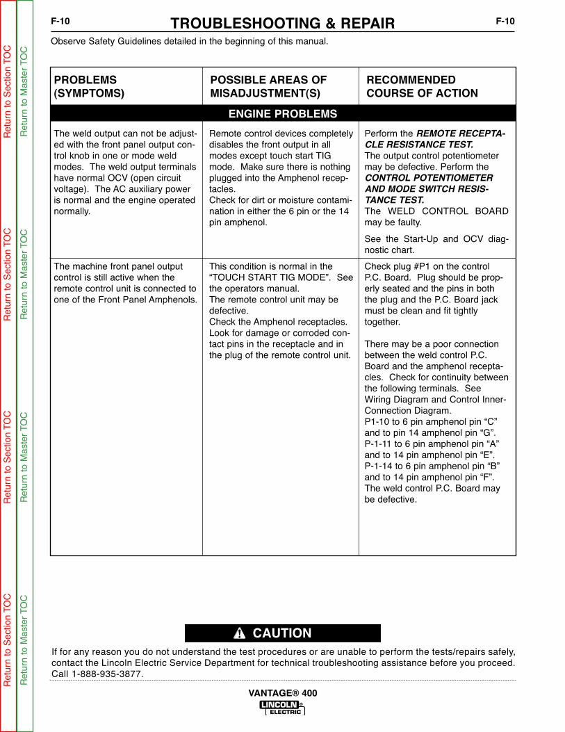
Observe Safety Guidelines detailed in the beginning of this manual.
If for any reason you do not understand the test procedures or are unable to perform the tests/repairs safely,contact the Lincoln Electric Service Department for technical troubleshooting assistance before you proceed.Call 1-888-935-3877.
CAUTION
TROUBLESHOOTING & REPAIRF-10 F-10
VANTAGE® 400
The machine front panel outputcontrol is still active when theremote control unit is connected toone of the Front Panel Amphenols.
This condition is normal in the“TOUCH START TIG MODE”. Seethe operators manual.The remote control unit may bedefective.Check the Amphenol receptacles.Look for damage or corroded con-tact pins in the receptacle and inthe plug of the remote control unit.
Check plug #P1 on the controlP.C. Board. Plug should be prop-erly seated and the pins in boththe plug and the P.C. Board jackmust be clean and fit tightlytogether.
There may be a poor connectionbetween the weld control P.C.Board and the amphenol recepta-cles. Check for continuity betweenthe following terminals. SeeWiring Diagram and Control Inner-Connection Diagram.P1-10 to 6 pin amphenol pin “C”and to pin 14 amphenol pin “G”.P-1-11 to 6 pin amphenol pin “A”and to 14 pin amphenol pin “E”.P-1-14 to 6 pin amphenol pin “B”and to 14 pin amphenol pin “F”.The weld control P.C. Board maybe defective.
PROBLEMS(SYMPTOMS)
POSSIBLE AREAS OFMISADJUSTMENT(S)
RECOMMENDEDCOURSE OF ACTION
ENGINE PROBLEMS
The weld output can not be adjust-ed with the front panel output con-trol knob in one or mode weldmodes. The weld output terminalshave normal OCV (open circuitvoltage). The AC auxiliary poweris normal and the engine operatednormally.
Remote control devices completelydisables the front output in allmodes except touch start TIGmode. Make sure there is nothingplugged into the Amphenol recep-tacles.Check for dirt or moisture contami-nation in either the 6 pin or the 14pin amphenol.
Perform the REMOTE RECEPTA-
CLE RESISTANCE TEST.
The output control potentiometermay be defective. Perform theCONTROL POTENTIOMETER
AND MODE SWITCH RESIS-
TANCE TEST.
The WELD CONTROL BOARDmay be faulty.
See the Start-Up and OCV diag-nostic chart.
Ret
urn
to S
ectio
n TO
CR
etur
n to
Sec
tion
TOC
Ret
urn
to S
ectio
n TO
CR
etur
n to
Sec
tion
TOC
Ret
urn
to M
aste
r TO
CR
etur
n to
Mas
ter
TOC
Ret
urn
to M
aste
r TO
CR
etur
n to
Mas
ter
TOC

Observe Safety Guidelines detailed in the beginning of this manual.
If for any reason you do not understand the test procedures or are unable to perform the tests/repairs safely,contact the Lincoln Electric Service Department for technical troubleshooting assistance before you proceed.Call 1-888-935-3877.
CAUTION
TROUBLESHOOTING & REPAIRF-11 F-11
VANTAGE® 400
PROBLEMS(SYMPTOMS)
POSSIBLE AREAS OFMISADJUSTMENT(S)
RECOMMENDEDCOURSE OF ACTION
ENGINE PROBLEMSThe machine seems to be lockedinto the “CC-stick” mode of opera-tion.
Check the position of the WELDMODE selector switch. The switchshould positively snap into eachmode position and should not feelgritty or get stuck between posi-tions.
Check that plug P-7 is fully seatedinto the weld control P.C. boardsocket. See Control Inner-Connection diagram.Check for corroded, dirty, or dam-aged Molex terminals in plug P-7,also check for similar problems insocket J-7 on the weld control P.C.board.Check the wiring between the con-trol P.C. Board and the modeswitch. Look for poor crimp andsolder connections as well asdamaged wiring or insulation. Seewiring diagram.Perform the CONTROL POTEN-
TIOMETER AND MODE SWITCH
RESISTANCE TEST.
The Weld control P.C. Board maybe faulty.
The arc quality is poor with exces-sive spatter. The arc heat can becontrolled and maintained normal-ly, the auxiliary output is normaland the engine operates normally.
The ARC CONTROL may be settoo high.The output control may be set toohigh for the electrode being used.Check that the electrode is ofgood quality, dry and free fromcontamination. Try using someLincoln Electrode, and setting themachine per Lincoln’s recommen-dation.If shielding gas is used, check thatthe gas and gas flow are correct.Check for damaged, pinched, orleaking gas lines.Check for proper work, and elec-trode leads and connections (size,length, coils, or bad connections).
Check that the weld circuit isn'tgrounded. With the engine off,check the resistance betweenchassis ground and the weld out-put terminals. The resistanceshould be very high, a minimum of500,000 (500k) Ohms.The weld control system may begrounded or malfunctioning.Perform the CONTROL POTEN-
TIOMETER and MODE SWITCH
TEST, and the REMOTE RECEP-
TACLE RESISTANCE TEST.
The Chopper module may bedefective. Perform the CHOPPER
MODULE RESISTANCE TEST.
Ret
urn
to S
ectio
n TO
CR
etur
n to
Sec
tion
TOC
Ret
urn
to S
ectio
n TO
CR
etur
n to
Sec
tion
TOC
Ret
urn
to M
aste
r TO
CR
etur
n to
Mas
ter
TOC
Ret
urn
to M
aste
r TO
CR
etur
n to
Mas
ter
TOC
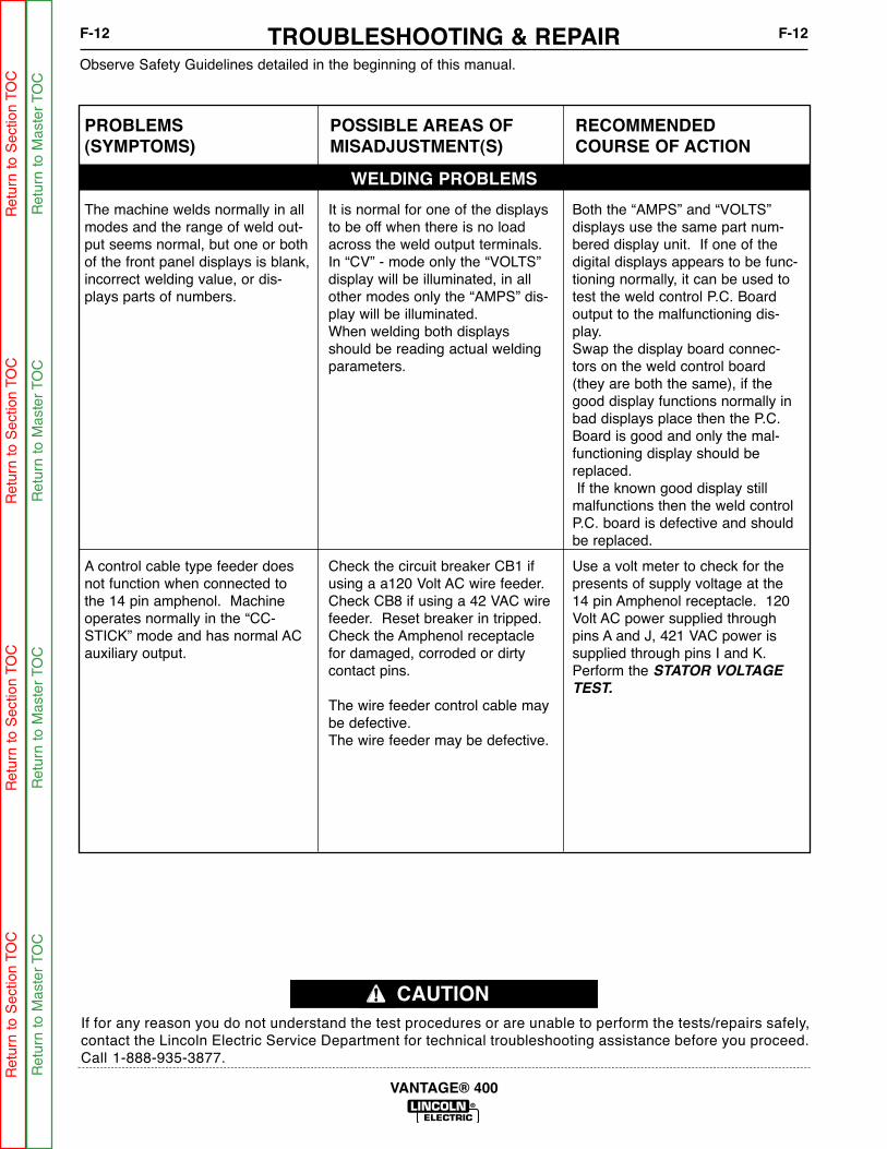
Observe Safety Guidelines detailed in the beginning of this manual.
If for any reason you do not understand the test procedures or are unable to perform the tests/repairs safely,contact the Lincoln Electric Service Department for technical troubleshooting assistance before you proceed.Call 1-888-935-3877.
CAUTION
TROUBLESHOOTING & REPAIRF-12 F-12
VANTAGE® 400
PROBLEMS(SYMPTOMS)
POSSIBLE AREAS OFMISADJUSTMENT(S)
RECOMMENDEDCOURSE OF ACTION
WELDING PROBLEMS
The machine welds normally in allmodes and the range of weld out-put seems normal, but one or bothof the front panel displays is blank,incorrect welding value, or dis-plays parts of numbers.
It is normal for one of the displaysto be off when there is no loadacross the weld output terminals.In “CV” - mode only the “VOLTS”display will be illuminated, in allother modes only the “AMPS” dis-play will be illuminated.When welding both displaysshould be reading actual weldingparameters.
Both the “AMPS” and “VOLTS”displays use the same part num-bered display unit. If one of thedigital displays appears to be func-tioning normally, it can be used totest the weld control P.C. Boardoutput to the malfunctioning dis-play.Swap the display board connec-tors on the weld control board(they are both the same), if thegood display functions normally inbad displays place then the P.C.Board is good and only the mal-functioning display should bereplaced.If the known good display still
malfunctions then the weld controlP.C. board is defective and shouldbe replaced.
A control cable type feeder doesnot function when connected tothe 14 pin amphenol. Machineoperates normally in the “CC-STICK” mode and has normal ACauxiliary output.
Check the circuit breaker CB1 ifusing a a120 Volt AC wire feeder.Check CB8 if using a 42 VAC wirefeeder. Reset breaker in tripped.Check the Amphenol receptaclefor damaged, corroded or dirtycontact pins.
The wire feeder control cable maybe defective.The wire feeder may be defective.
Use a volt meter to check for thepresents of supply voltage at the14 pin Amphenol receptacle. 120Volt AC power supplied throughpins A and J, 421 VAC power issupplied through pins I and K.Perform the STATOR VOLTAGE
TEST.
Ret
urn
to S
ectio
n TO
CR
etur
n to
Sec
tion
TOC
Ret
urn
to S
ectio
n TO
CR
etur
n to
Sec
tion
TOC
Ret
urn
to M
aste
r TO
CR
etur
n to
Mas
ter
TOC
Ret
urn
to M
aste
r TO
CR
etur
n to
Mas
ter
TOC
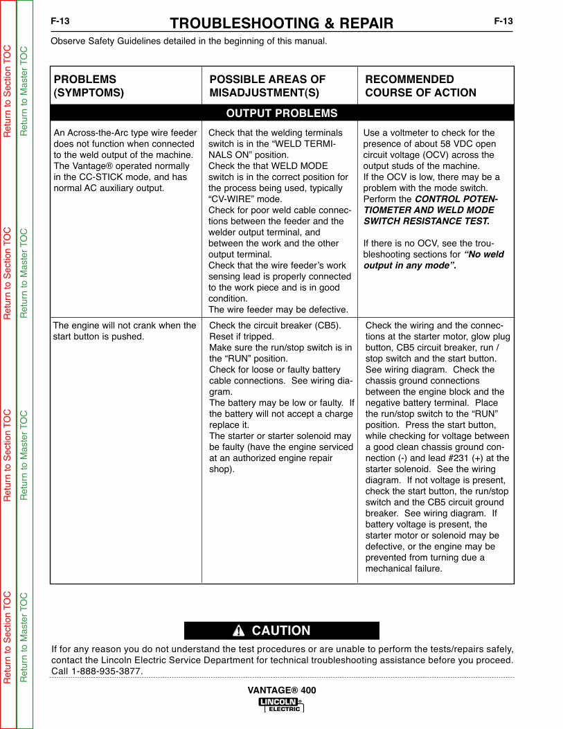
The engine will not crank when thestart button is pushed.
Check the circuit breaker (CB5).Reset if tripped.Make sure the run/stop switch is inthe “RUN” position.Check for loose or faulty batterycable connections. See wiring dia-gram.The battery may be low or faulty. Ifthe battery will not accept a chargereplace it.The starter or starter solenoid maybe faulty (have the engine servicedat an authorized engine repairshop).
Check the wiring and the connec-tions at the starter motor, glow plugbutton, CB5 circuit breaker, run /stop switch and the start button.See wiring diagram. Check thechassis ground connectionsbetween the engine block and thenegative battery terminal. Placethe run/stop switch to the “RUN”position. Press the start button,while checking for voltage betweena good clean chassis ground con-nection (-) and lead #231 (+) at thestarter solenoid. See the wiringdiagram. If not voltage is present,check the start button, the run/stopswitch and the CB5 circuit groundbreaker. See wiring diagram. Ifbattery voltage is present, thestarter motor or solenoid may bedefective, or the engine may beprevented from turning due amechanical failure.
Observe Safety Guidelines detailed in the beginning of this manual.
If for any reason you do not understand the test procedures or are unable to perform the tests/repairs safely,contact the Lincoln Electric Service Department for technical troubleshooting assistance before you proceed.Call 1-888-935-3877.
CAUTION
TROUBLESHOOTING & REPAIRF-13 F-13
VANTAGE® 400
PROBLEMS(SYMPTOMS)
POSSIBLE AREAS OFMISADJUSTMENT(S)
RECOMMENDEDCOURSE OF ACTION
OUTPUT PROBLEMS
An Across-the-Arc type wire feederdoes not function when connectedto the weld output of the machine.The Vantage® operated normallyin the CC-STICK mode, and hasnormal AC auxiliary output.
Check that the welding terminalsswitch is in the “WELD TERMI-NALS ON” position.Check the that WELD MODEswitch is in the correct position forthe process being used, typically“CV-WIRE” mode.Check for poor weld cable connec-tions between the feeder and thewelder output terminal, andbetween the work and the otheroutput terminal.Check that the wire feeder’s worksensing lead is properly connectedto the work piece and is in goodcondition.The wire feeder may be defective.
Use a voltmeter to check for thepresence of about 58 VDC opencircuit voltage (OCV) across theoutput studs of the machine.If the OCV is low, there may be aproblem with the mode switch.Perform the CONTROL POTEN-
TIOMETER AND WELD MODE
SWITCH RESISTANCE TEST.
If there is no OCV, see the trou-bleshooting sections for “No weld
output in any mode”.
Ret
urn
to S
ectio
n TO
CR
etur
n to
Sec
tion
TOC
Ret
urn
to S
ectio
n TO
CR
etur
n to
Sec
tion
TOC
Ret
urn
to M
aste
r TO
CR
etur
n to
Mas
ter
TOC
Ret
urn
to M
aste
r TO
CR
etur
n to
Mas
ter
TOC
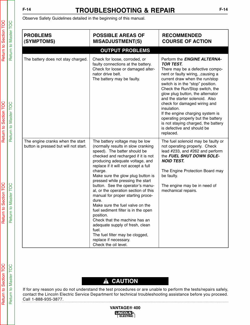
The engine cranks when the startbutton is pressed but will not start.
The battery voltage may be low(normally results in slow crankingspeed). The batter should bechecked and recharged if it is notproducing adequate voltage, andreplace if it will not accept a fullcharge.Make sure the glow plug button ispressed while pressing the startbutton. See the operator’s manu-al, or the operation section of thismanual for proper starting proce-dure.Make sure the fuel valve on thefuel sediment filter is in the openposition.Check that the machine has anadequate supply of fresh, cleanfuel.The fuel filter may be clogged,replace if necessary.Check the oil level.
The fuel solenoid may be faulty ornot operating properly. Checklead #233, and #262 and performthe FUEL SHUT DOWN SOLE-
NOID TEST.
The Engine Protection Board maybe faulty.
The engine may be in need ofmechanical repairs.
Observe Safety Guidelines detailed in the beginning of this manual.
If for any reason you do not understand the test procedures or are unable to perform the tests/repairs safely,contact the Lincoln Electric Service Department for technical troubleshooting assistance before you proceed.Call 1-888-935-3877.
CAUTION
TROUBLESHOOTING & REPAIRF-14 F-14
VANTAGE® 400
PROBLEMS(SYMPTOMS)
POSSIBLE AREAS OFMISADJUSTMENT(S)
RECOMMENDEDCOURSE OF ACTION
OUTPUT PROBLEMS
The battery does not stay charged. Check for loose, corroded, orfaulty connections at the battery.Check for loose or damaged alter-nator drive belt.The battery may be faulty.
Perform the ENGINE ALTERNA-
TOR TEST.
There may be a defective compo-nent or faulty wiring, ,causing acurrent draw when the run/stopswitch is in the “stop” position.Check the Run/Stop switch, theglow plug button, the alternatorand the starter solenoid. Alsocheck for damaged wiring andinsulation.If the engine charging system isoperating properly but the batteryis not staying charged, the batteryis defective and should bereplaced.
Ret
urn
to S
ectio
n TO
CR
etur
n to
Sec
tion
TOC
Ret
urn
to S
ectio
n TO
CR
etur
n to
Sec
tion
TOC
Ret
urn
to M
aste
r TO
CR
etur
n to
Mas
ter
TOC
Ret
urn
to M
aste
r TO
CR
etur
n to
Mas
ter
TOC

The engine shuts down shortlyafter starting.
Check for adequate supply ofclean fresh fuel.Check fuel and air filters, replace ifnecessary.Check oil level, add oil asrequired. Look for oil leakage.Check for loose or faulty batterycable connections.
The oil pressure switch or coolanttemperature switch may be faulty.Make sure the engine has oil andoil pressure and engine is notoverheated.Disconnect lead 234 from EngineProtection PC Board, of enginecontinues to run oil pressureswitch or Temperature Switch isfaulty. Check for faulty run/stop switch.Check for damaged insulation inthe wiring between the engine pro-tection relay and the oil pressureand coolant temperature switches.See wiring diagram.
Observe Safety Guidelines detailed in the beginning of this manual.
If for any reason you do not understand the test procedures or are unable to perform the tests/repairs safely,contact the Lincoln Electric Service Department for technical troubleshooting assistance before you proceed.Call 1-888-935-3877.
CAUTION
TROUBLESHOOTING & REPAIRF-15 F-15
VANTAGE® 400
PROBLEMS(SYMPTOMS)
POSSIBLE AREAS OFMISADJUSTMENT(S)
RECOMMENDEDCOURSE OF ACTION
OUTPUT PROBLEMS
The engine starts but shuts downimmediately when the start buttonis released.
Make sure the glow plug button ispressed while pushing the startbutton, and held until the engineprotection light turns off (5 SEC-ONDS MAXIMUM AFTER THEENGINE STARTS.). See the oper-ator’s manual, or the operatingsection of this manual for properstarting procedure.Check the oil level.Be certain that the engine is notoverheated.Check that the machine had ade-quate supply of fresh, clean fuel.The fuel filter may be clogged.Replace if necessary.
The shut down fuel solenoid maybe faulty or not operating properly.Check lead #233 and #262 andperform the FUEL SHUT DOWN
SOLENOID TEST. See wiringdiagram.The check for the presents of 12volts at the lead #233, when startbutton is pushed. Check CB5,and lead #231.
The Engine Protection Board maybe faulty.
The engine may have inadequateoil pressure.
The oil pressure switch or coolanttemperature switch may be faulty.
Ret
urn
to S
ectio
n TO
CR
etur
n to
Sec
tion
TOC
Ret
urn
to S
ectio
n TO
CR
etur
n to
Sec
tion
TOC
Ret
urn
to M
aste
r TO
CR
etur
n to
Mas
ter
TOC
Ret
urn
to M
aste
r TO
CR
etur
n to
Mas
ter
TOC

Observe Safety Guidelines detailed in the beginning of this manual.
If for any reason you do not understand the test procedures or are unable to perform the tests/repairs safely,contact the Lincoln Electric Service Department for technical troubleshooting assistance before you proceed.Call 1-888-935-3877.
CAUTION
TROUBLESHOOTING & REPAIRF-16 F-16
VANTAGE® 400
PROBLEMS(SYMPTOMS)
POSSIBLE AREAS OFMISADJUSTMENT(S)
RECOMMENDEDCOURSE OF ACTION
OUTPUT PROBLEMS
The engine shuts down shortlyafter starting.
Check for poor electrical connec-tions at the run/stop switch, andthe fuel shutdown solenoid. See
wiring diagram.
The fuel solenoid may be faulty.Perform the FUEL SHUTDOWN
SOLENOID TEST.
The engine shuts down shortlyafter starting and trips the batterycircuit breaker (CB5).
Try resetting the breaker. If it tripsagain do not attempt to use themachine.
Contact a Lincoln Authorized FieldService Shop.
Repeated tripping and resetting ofthe circuit breaker can damage it,or alter its trip point. If the breakerhas been ripped and reset manytimes, it should be replaced.Examine the CB5 circuit breaker,run/stop switch. Start button.Shut-down and idle solenoid,engine protection board, fuelgauge and sender, and all thewiring connecting these compo-nents. Look for damaged or out ofplace wiring that may be in contactwith other conductors or chassisground. See wiring diagram.
Perform the IDLER SOLENOID
TEST.
Perform the FUEL SHUTDOWN
SOLENOID TEST.
The Engine Protection PC Boardmay be defective.
Ret
urn
to S
ectio
n TO
CR
etur
n to
Sec
tion
TOC
Ret
urn
to S
ectio
n TO
CR
etur
n to
Sec
tion
TOC
Ret
urn
to M
aste
r TO
CR
etur
n to
Mas
ter
TOC
Ret
urn
to M
aste
r TO
CR
etur
n to
Mas
ter
TOC
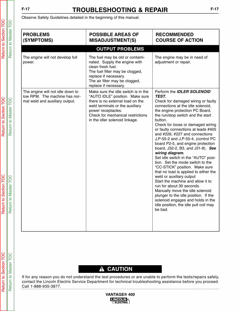
Observe Safety Guidelines detailed in the beginning of this manual.
If for any reason you do not understand the test procedures or are unable to perform the tests/repairs safely,contact the Lincoln Electric Service Department for technical troubleshooting assistance before you proceed.Call 1-888-935-3877.
CAUTION
TROUBLESHOOTING & REPAIRF-17 F-17
VANTAGE® 400
PROBLEMS(SYMPTOMS)
POSSIBLE AREAS OFMISADJUSTMENT(S)
RECOMMENDEDCOURSE OF ACTION
OUTPUT PROBLEMS
The engine will not develop fullpower.
The fuel may be old or contami-nated. Supply the engine withclean fresh fuel.The fuel filter may be clogged,replace if necessary.The air filter may be clogged,replace if necessary.
The engine may be in need ofadjustment or repair.
The engine will not idle down tolow RPM. The machine has nor-mal weld and auxiliary output.
Make sure the idle switch is in the“AUTO IDLE” position. Make surethere is no external load on theweld terminals or the auxiliarypower receptacles.Check for mechanical restrictionsin the idler solenoid linkage.
Perform the IDLER SOLENOID
TEST.
Check for damaged wiring or faultyconnections at the idle solenoid,the engine protection PC Board,the run/stop switch and the startbutton.Check for loose or damaged wiringor faulty connections at leads #405and #226, #227 and connectionsJ,P-55-2 and J,P-55-4, (control PCboard P2-5, and engine protectionboard, J32-2, B3, and J31-8). See
wiring diagram.
Set idle switch in the “AUTO” posi-tion. Set the mode switch to the“CC-STICK” position. Make surethat no load is applied to either theweld or auxiliary outputStart the machine and allow it torun for about 30 seconds.Manually move the idle solenoidplunger to the idle position. If thesolenoid engages and holds in theidle position, the idle pull coil maybe bad.
Ret
urn
to S
ectio
n TO
CR
etur
n to
Sec
tion
TOC
Ret
urn
to S
ectio
n TO
CR
etur
n to
Sec
tion
TOC
Ret
urn
to M
aste
r TO
CR
etur
n to
Mas
ter
TOC
Ret
urn
to M
aste
r TO
CR
etur
n to
Mas
ter
TOC
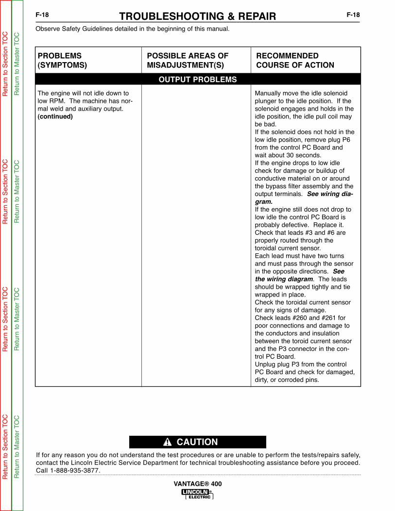
Observe Safety Guidelines detailed in the beginning of this manual.
If for any reason you do not understand the test procedures or are unable to perform the tests/repairs safely,contact the Lincoln Electric Service Department for technical troubleshooting assistance before you proceed.Call 1-888-935-3877.
CAUTION
TROUBLESHOOTING & REPAIRF-18 F-18
VANTAGE® 400
Ret
urn
to S
ectio
n TO
CR
etur
n to
Sec
tion
TOC
Ret
urn
to S
ectio
n TO
CR
etur
n to
Sec
tion
TOC
Ret
urn
to M
aste
r TO
CR
etur
n to
Mas
ter
TOC
Ret
urn
to M
aste
r TO
CR
etur
n to
Mas
ter
TOC
PROBLEMS(SYMPTOMS)
POSSIBLE AREAS OFMISADJUSTMENT(S)
RECOMMENDEDCOURSE OF ACTION
OUTPUT PROBLEMS
The engine will not idle down tolow RPM. The machine has nor-mal weld and auxiliary output.(continued)
Manually move the idle solenoidplunger to the idle position. If thesolenoid engages and holds in theidle position, the idle pull coil maybe bad. If the solenoid does not hold in thelow idle position, remove plug P6from the control PC Board andwait about 30 seconds. If the engine drops to low idlecheck for damage or buildup ofconductive material on or aroundthe bypass filter assembly and theoutput terminals. See wiring dia-
gram.
If the engine still does not drop tolow idle the control PC Board isprobably defective. Replace it.Check that leads #3 and #6 areproperly routed through thetoroidal current sensor.Each lead must have two turnsand must pass through the sensorin the opposite directions. See
the wiring diagram. The leadsshould be wrapped tightly and tiewrapped in place.Check the toroidal current sensorfor any signs of damage.Check leads #260 and #261 forpoor connections and damage tothe conductors and insulationbetween the toroid current sensorand the P3 connector in the con-trol PC Board.Unplug plug P3 from the controlPC Board and check for damaged,dirty, or corroded pins.

Observe Safety Guidelines detailed in the beginning of this manual.
If for any reason you do not understand the test procedures or are unable to perform the tests/repairs safely,contact the Lincoln Electric Service Department for technical troubleshooting assistance before you proceed.Call 1-888-935-3877.
CAUTION
TROUBLESHOOTING & REPAIRF-19 F-19
VANTAGE® 400
PROBLEMS(SYMPTOMS)
POSSIBLE AREAS OFMISADJUSTMENT(S)
RECOMMENDEDCOURSE OF ACTION
OUTPUT PROBLEMS
The engine will not idle down tolow RPM. The machine has nor-mal weld and auxiliary output.(continued)
Measure the resistance of toroidalcurrent sensor. Measure between#P-3 and #P-4, the resistanceshould be 4.1 Ohms.If the sensor is shorted or openreplace it.The control board may be bad.
The engine will not go to high idlewhen using auxiliary power.Auxiliary power is normal when theidler switch is in the “HIGH” idleposition, the automatic idle func-tion works properly when welding.
The load on the auxiliary recepta-cle may be too low.The automatic idle system will notfunction reliably if the low is lessthan 100 Watts.The device connected to the auxil-iary power may be defective tryanother device.Make sure the connections to theauxiliary device are tight.Some device are designed tosense for adequate input power.Product of this type may not turnon due to low voltage and frequen-cy of the idling machine. If thishappens the current draw will like-ly be insufficient to activate theautomatic idle system. Device ofthis type may require that the Idlerswitch be in the “HIGH IDLE” posi-tion.
Check that leads #3 and #6 areproperly routed through thetoroidal current sensor.Each lead must have two turnsand must pass through the sensorin the opposite directions. Seewiring diagram. The leads shouldbe wrapped tightly and tiewrapped in place.Check the toroidal current sensorfor any signs of damage.Check leads #260 and #261 forpoor connections and damage tothe conductors and insulationbetween the toroid current sensorand the P3 connector in the con-trol PC board.Unplug plug P3 from the controlPC board and check for damaged,dirty, or corroded pins.Measure the resistance of thetoroidal current sensor. Measurebetween #P-3 and P-4, the resis-tance should be 10-14 Ohms.If the sensor is shorted or openreplace it.The control P.C. Board may bedefective.
Ret
urn
to S
ectio
n TO
CR
etur
n to
Sec
tion
TOC
Ret
urn
to S
ectio
n TO
CR
etur
n to
Sec
tion
TOC
Ret
urn
to M
aste
r TO
CR
etur
n to
Mas
ter
TOC
Ret
urn
to M
aste
r TO
CR
etur
n to
Mas
ter
TOC

Observe Safety Guidelines detailed in the beginning of this manual.
If for any reason you do not understand the test procedures or are unable to perform the tests/repairs safely,contact the Lincoln Electric Service Department for technical troubleshooting assistance before you proceed.Call 1-888-935-3877.
CAUTION
TROUBLESHOOTING & REPAIRF-20 F-20
VANTAGE® 400
PROBLEMS(SYMPTOMS)
POSSIBLE AREAS OFMISADJUSTMENT(S)
RECOMMENDEDCOURSE OF ACTION
OUTPUT PROBLEMS
The engine will not go to high idlewhen striking arc. The automaticidle system functions normallywhen using auxiliary power.Welding and auxiliary outputs arenormal when the idle switch is inthe “HIGH IDLE” position.
Check that the welding cables arein good working condition and theconnections are tight. Make surethe work clamp is attached toclean, bare metal.
Check the leads and connectionsat the SHUNT at the Positive out-put stud. Check lead 204S and206S for continuity from the shuntto J-6 on the Weld Control Board.Check the pins and connections atJ-6 and J on the Weld ControlBoard.The weld control P.C. Board maybe defective.
The engine will not go to high idlewhen attempting to strike and arc,or when a load is applied to any ofthe auxiliary power receptacles.
Check that the welding cables andthe auxiliary power lead connec-tions are tight.
The weld control P.C. Board maybe defective.
The engine goes to low idle, butwill not stay low idle.
Make sure there are no auxiliaryloads on either the weld terminalsor the auxiliary receptacles.Check that the welding cables andthe auxiliary cables and the auxil-iary power lead connections aretight and that the insulation is notdamaged.
The Idler solenoid linkage may bedamaged or out of adjustment.Make sure the solenoid plunger isable to fully ease against the inter-nal stop of the solenoid coilassembly. The low idle RPM may be too low.Perform the ENGINE THROTTLE
ADJUSTMENT TEST.
The solenoid hold coil power cir-cuit may be defective. Performthe IDLER SOLENOID TEST.
The solenoid hold coil power cir-cuit may be faulty. Check wiringand connections on lead #210Aand lead #215. The weld control PC Board maybe defective.
Ret
urn
to S
ectio
n TO
CR
etur
n to
Sec
tion
TOC
Ret
urn
to S
ectio
n TO
CR
etur
n to
Sec
tion
TOC
Ret
urn
to M
aste
r TO
CR
etur
n to
Mas
ter
TOC
Ret
urn
to M
aste
r TO
CR
etur
n to
Mas
ter
TOC

Service and repair should be performed by only Lincoln Electric factory trained personnel.Unauthorized repairs performed on this equipment may result in danger to the technicianor machine operator and will invalidate your factory warranty. For your safety and to avoidelectrical shock, please observe all safety notes and precautions detailed throughout thismanual.
If for any reason you do not understand the test procedures or are unable to perform thetest/repairs safely, contact the Lincoln Electric Service Department for electrical trou-bleshooting assistance before you proceed. Call 1-888-935-3877.
TEST DESCRIPTION
This procedure will aid the technician in the removal and replacement of the case sheetmetal covers.
MATERIALS NEEDED
3/8" wrench
1/2" wrench
CASE COVER REMOVAL AND REPLACEMENT PROCEDURE
WARNING
TROUBLESHOOTING & REPAIRF-21 F-21
VANTAGE® 400
Ret
urn
to S
ectio
n TO
CR
etur
n to
Sec
tion
TOC
Ret
urn
to S
ectio
n TO
CR
etur
n to
Sec
tion
TOC
Ret
urn
to M
aste
r TO
CR
etur
n to
Mas
ter
TOC
Ret
urn
to M
aste
r TO
CR
etur
n to
Mas
ter
TOC
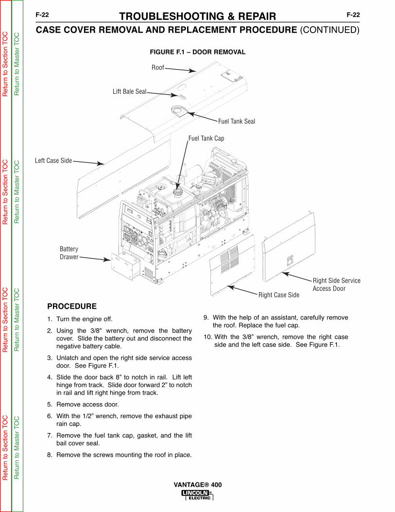
BatteryDrawer
Left Case Side
Roof
Lift Bale Seal
Fuel Tank Seal
Right Side ServiceAccess Door
Right Case Side
Fuel Tank Cap
FIGURE F.1 – DOOR REMOVAL
CASE COVER REMOVAL AND REPLACEMENT PROCEDURE (CONTINUED)
PROCEDURE
1. Turn the engine off.
2. Using the 3/8" wrench, remove the batterycover. Slide the battery out and disconnect thenegative battery cable.
3. Unlatch and open the right side service accessdoor. See Figure F.1.
4. Slide the door back 8” to notch in rail. Lift lefthinge from track. Slide door forward 2” to notchin rail and lift right hinge from track.
5. Remove access door.
6. With the 1/2” wrench, remove the exhaust piperain cap.
7. Remove the fuel tank cap, gasket, and the liftbail cover seal.
8. Remove the screws mounting the roof in place.
9. With the help of an assistant, carefully removethe roof. Replace the fuel cap.
10. With the 3/8” wrench, remove the right caseside and the left case side. See Figure F.1.
TROUBLESHOOTING & REPAIRF-22 F-22
VANTAGE® 400
Ret
urn
to S
ectio
n TO
CR
etur
n to
Sec
tion
TOC
Ret
urn
to S
ectio
n TO
CR
etur
n to
Sec
tion
TOC
Ret
urn
to M
aste
r TO
CR
etur
n to
Mas
ter
TOC
Ret
urn
to M
aste
r TO
CR
etur
n to
Mas
ter
TOC

CASE COVER REMOVAL AND REPLACEMENT PROCEDURE (CONTINUED)TROUBLESHOOTING & REPAIRF-23 F-23
VANTAGE® 400
REASSEMBLY PROCEDURE
1. Install components in reverse order of removal.
2. Be sure components align correctly.
3. Reconnect battery and replace battery door.
Ret
urn
to S
ectio
n TO
CR
etur
n to
Sec
tion
TOC
Ret
urn
to S
ectio
n TO
CR
etur
n to
Sec
tion
TOC
Ret
urn
to M
aste
r TO
CR
etur
n to
Mas
ter
TOC
Ret
urn
to M
aste
r TO
CR
etur
n to
Mas
ter
TOC

NOTESF-24 F-24
VANTAGE® 400
Ret
urn
to S
ectio
n TO
CR
etur
n to
Sec
tion
TOC
Ret
urn
to S
ectio
n TO
CR
etur
n to
Sec
tion
TOC
Ret
urn
to M
aste
r TO
CR
etur
n to
Mas
ter
TOC
Ret
urn
to M
aste
r TO
CR
etur
n to
Mas
ter
TOC
Service and repair should be performed by only Lincoln Electric factory trained personnel.Unauthorized repairs performed on this equipment may result in danger to the technicianor machine operator and will invalidate your factory warranty. For your safety and to avoidelectrical shock, please observe all safety notes and precautions detailed throughout thismanual.
If for any reason you do not understand the test procedures or are unable to perform thetest/repairs safely, contact the Lincoln Electric Service Department for electrical trou-bleshooting assistance before you proceed. Call 1-888-935-3877.
TEST DESCRIPTION
This procedure will insure that the large capacitors in the chopper module have been dis-charged. This procedure should be performed whenever work is to be attempted on ornear the chopper module.
MATERIALS NEEDED
Miscellaneous hand toolsVolt/OhmmeterResistor (25-1000 ohms and 25 watts minimum)
Lincoln part #S10404-114 works well for this purposeJumper leadsWiring Diagram
CHOPPER MODULE CAPACITOR DISCHARGE PROCEDURE
WARNING
TROUBLESHOOTING & REPAIRF-25 F-25
VANTAGE® 400
Ret
urn
to S
ectio
n TO
CR
etur
n to
Sec
tion
TOC
Ret
urn
to S
ectio
n TO
CR
etur
n to
Sec
tion
TOC
Ret
urn
to M
aste
r TO
CR
etur
n to
Mas
ter
TOC
Ret
urn
to M
aste
r TO
CR
etur
n to
Mas
ter
TOC
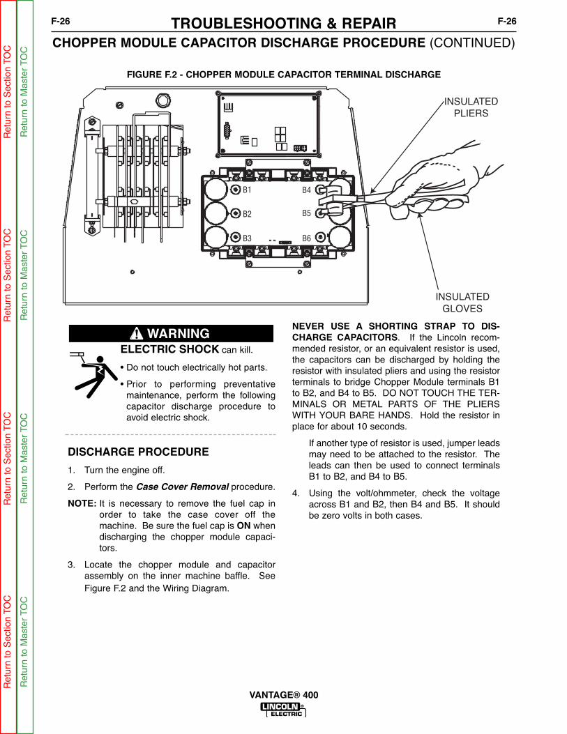
B1
B2
B3 B6
B5
B4
INSULATEDGLOVES
INSULATEDPLIERS
FIGURE F.2 - CHOPPER MODULE CAPACITOR TERMINAL DISCHARGE
CHOPPER MODULE CAPACITOR DISCHARGE PROCEDURE (CONTINUED)TROUBLESHOOTING & REPAIRF-26 F-26
VANTAGE® 400
ELECTRIC SHOCK can kill.
• Do not touch electrically hot parts.
• Prior to performing preventativemaintenance, perform the followingcapacitor discharge procedure toavoid electric shock.
DISCHARGE PROCEDURE
1. Turn the engine off.
2. Perform the Case Cover Removal procedure.
NOTE: It is necessary to remove the fuel cap inorder to take the case cover off themachine. Be sure the fuel cap is ON whendischarging the chopper module capaci-tors.
3. Locate the chopper module and capacitorassembly on the inner machine baffle. SeeFigure F.2 and the Wiring Diagram.
NEVER USE A SHORTING STRAP TO DIS-CHARGE CAPACITORS. If the Lincoln recom-mended resistor, or an equivalent resistor is used,the capacitors can be discharged by holding theresistor with insulated pliers and using the resistorterminals to bridge Chopper Module terminals B1to B2, and B4 to B5. DO NOT TOUCH THE TER-MINALS OR METAL PARTS OF THE PLIERSWITH YOUR BARE HANDS. Hold the resistor inplace for about 10 seconds.
If another type of resistor is used, jumper leadsmay need to be attached to the resistor. Theleads can then be used to connect terminalsB1 to B2, and B4 to B5.
4. Using the volt/ohmmeter, check the voltageacross B1 and B2, then B4 and B5. It shouldbe zero volts in both cases.
WARNING
Ret
urn
to S
ectio
n TO
CR
etur
n to
Sec
tion
TOC
Ret
urn
to S
ectio
n TO
CR
etur
n to
Sec
tion
TOC
Ret
urn
to M
aste
r TO
CR
etur
n to
Mas
ter
TOC
Ret
urn
to M
aste
r TO
CR
etur
n to
Mas
ter
TOC

Service and repair should be performed by only Lincoln Electric factory trained personnel.Unauthorized repairs performed on this equipment may result in danger to the technicianor machine operator and will invalidate your factory warranty. For your safety and to avoidelectrical shock, please observe all safety notes and precautions detailed throughout thismanual.
If for any reason you do not understand the test procedures or are unable to perform thetest/repairs safely, contact the Lincoln Electric Service Department for electrical trou-bleshooting assistance before you proceed. Call 1-888-935-3877.
TEST DESCRIPTION
This test will determine if the shutdown solenoid resistance values are normal, and alsodetermine if it will function normally when energized with 12 VDC.
MATERIALS NEEDED
Wiring DiagramVolt/OhmmeterMiscellaneous hand tools12 volt D.C. power source, (an automotive battery works well)
FUEL SHUTDOWN SOLENOID TEST
WARNING
TROUBLESHOOTING & REPAIRF-27 F-27
VANTAGE® 400
Ret
urn
to S
ectio
n TO
CR
etur
n to
Sec
tion
TOC
Ret
urn
to S
ectio
n TO
CR
etur
n to
Sec
tion
TOC
Ret
urn
to M
aste
r TO
CR
etur
n to
Mas
ter
TOC
Ret
urn
to M
aste
r TO
CR
etur
n to
Mas
ter
TOC

VANTAGE 400
LINCOLNELECTRIC
SHUTDOWN SOLENOIDIDLE SOLENOID
FIGURE F.3 - FUEL SHUTDOWN SOLENOID LOCATION
FUEL SHUTDOWN SOLENOID TEST (CONTINUED)
TEST PROCEDURE
1. Turn the engine off.
2. Open the right side engine service accessdoor.
3. Locate the fuel solenoid, located on top of theengine.
4. Locate and unplug harness connection 56.Cut any necessary cable ties. See Figure F.4.
See Wiring Diagram.
5. Check the coil resistance, (black wire to redwire). The normal resistance is approximately9 ohms. Check the Resistance between theblack wire and a clean, unpainted chassisground. The resistance should be very high,500,000 Ohms or more. If any of the aboveresistance values are incorrect, the solenoidmay be faulty. Replace.
6. Using an external 12VDC supply, apply volt-age to the coil leads, (black-) to (white+). Thesolenoid should activate.
If the solenoid does not operate correctlywhen 12VDC is applied, the solenoid may bedefective. Replace.
Re-connect fuel solenoid and replace anypreviously removed cable ties.
7. If finished testing, close the engine serviceaccess doors.
TROUBLESHOOTING & REPAIRF-28 F-28
VANTAGE® 400
Ret
urn
to S
ectio
n TO
CR
etur
n to
Sec
tion
TOC
Ret
urn
to S
ectio
n TO
CR
etur
n to
Sec
tion
TOC
Ret
urn
to M
aste
r TO
CR
etur
n to
Mas
ter
TOC
Ret
urn
to M
aste
r TO
CR
etur
n to
Mas
ter
TOC

Service and repair should be performed by only Lincoln Electric factory trained personnel.Unauthorized repairs performed on this equipment may result in danger to the technicianor machine operator and will invalidate your factory warranty. For your safety and to avoidelectrical shock, please observe all safety notes and precautions detailed throughout thismanual.
If for any reason you do not understand the test procedures or are unable to perform thetest/repairs safely, contact the Lincoln Electric Service Department for electrical trou-bleshooting assistance before you proceed. Call 1-888-935-3877.
TEST DESCRIPTION
If the machine output is low or high, this test will determine whether the engine is operat-ing at the correct speed (RPM) during both HIGH and LOW idle conditions. You can checkRPM using a strobe-tach, a frequency counter, or a vibratach. Directions for adjusting thethrottle to the correct RPM are given.
MATERIALS NEEDED
Miscellaneous hand tools and metric wrench setHigh visibility markerStrobe-tach, frequency counter, or vibratach
ENGINE THROTTLE ADJUSTMENT TEST
WARNING
TROUBLESHOOTING & REPAIRF-29 F-29
VANTAGE® 400
Ret
urn
to S
ectio
n TO
CR
etur
n to
Sec
tion
TOC
Ret
urn
to S
ectio
n TO
CR
etur
n to
Sec
tion
TOC
Ret
urn
to M
aste
r TO
CR
etur
n to
Mas
ter
TOC
Ret
urn
to M
aste
r TO
CR
etur
n to
Mas
ter
TOC

STROBE
TACH
MARK
FIGURE F.4 - STROBE MARK LOCATION
ENGINE THROTTLE ADJUSTMENT TEST (CONTINUED)
TEST PROCEDURE
Strobe-Tach Method
1. Turn the engine off
2. open the top and right side engine serviceaccess doors.
3. Place a highly visible mark on the engine cool-ing fan blade. See Figure F.4.
4. Connect the strobe-tach according to the man-ufacturer’s instructions.
5. Start the engine and place the idle switch in the“HIGH IDLE” position. Make sure that there isno load on the machine.
6. Direct the strobe-tach light on the fan bladethat had been marked earlier, and synchronizethe light with the rotating mark. See thestrobe-tach manufacturer instructions.
The tach should read between 1860 and 1890RPM.
7. Move the idle switch to the “AUTO IDLE” posi-tion and wait for the idle solenoid to energize,and the engine RPM to drop and stabilize atthe low idle RPM.
8. Synchronize the strobe-tach to read the lowidle RPM.
Low idle speed should be 1300-1400 RPM.
If either of the readings is incorrect, proceed tothe THROTTLE ADJUSTMENT PROCE-
DURE later in this section.
TROUBLESHOOTING & REPAIRF-30 F-30
VANTAGE® 400
Ret
urn
to S
ectio
n TO
CR
etur
n to
Sec
tion
TOC
Ret
urn
to S
ectio
n TO
CR
etur
n to
Sec
tion
TOC
Ret
urn
to M
aste
r TO
CR
etur
n to
Mas
ter
TOC
Ret
urn
to M
aste
r TO
CR
etur
n to
Mas
ter
TOC

VANTAGE 400
LINCOLNELECTRIC
SHUTDOWN SOLENOIDIDLE SOLENOID
LOW SPEED ADJ.
DO NOT TOUCH FOR LOW SPEED
HIGH SPEED ADJ.
FIGURE F.5 - SOLENOID
ENGINE THROTTLE ADJUSTMENT TEST (CONTINUED)
Frequency Counter Method
NOTE: A dedicated frequency counter can beused for this test, but many high quality digital mul-timeters also have this function, and can be easilyutilized. See the manufacturer instructions for yourfrequency counter or multimeter.
1. Set your frequency counter per the meter man-ufacturer instructions, and plug it into one ofthe 120VAC auxiliary receptacles.
2. Start the engine and place the idle switch in the“HIGH IDLE” position. Make sure that there isno load on the machine.
The frequency should read between 62.0 and63.0 Hz.
3. Move the idle switch to the “AUTO IDLE” posi-tion and wait for the idle solenoid to energize,and the engine RPM to drop and stabilize atthe low idle RPM.
The frequency should read between 43.3 and46.6 Hz.
If either of the readings is incorrect, proceed tothe THROTTLE ADJUSTMENT PROCE-
DURE later in this section.
NOTE: For the VANTAGE® 400, and any otherLincoln Electric 1800 RPM (4 Pole) machine,engine RPM can be determined by multiplying thefrequency, in Hz. By 30. (Example: 30 Hz * 62 =1860RPM)
TROUBLESHOOTING & REPAIRF-31 F-31
VANTAGE® 400
Ret
urn
to S
ectio
n TO
CR
etur
n to
Sec
tion
TOC
Ret
urn
to S
ectio
n TO
CR
etur
n to
Sec
tion
TOC
Ret
urn
to M
aste
r TO
CR
etur
n to
Mas
ter
TOC
Ret
urn
to M
aste
r TO
CR
etur
n to
Mas
ter
TOC
ENGINE THROTTLE ADJUSTMENT TEST (CONTINUED)
Vibratach Method
A Vibratach is used to measure the vibrationscaused by the running engine. It can be positionedanywhere where the engine vibration is reasonablystrong. The best results will likely be obtained byopening the top engine cover and placing theVibratach directly against the top of the engine.
Read and understand the manufacturer’s instruc-tions for the Vibratach.
1. Start the engine and place the idle switch in the“HIGH IDLE” position. Make sure that there isno load on the machine.
2. Position and adjust the Vibratach; it shouldread between 1860 and 1890 RPM.
3. Move the idle switch to the “AUTO IDLE” posi-tion and wait for the idle solenoid to energize,and the engine RPM to drop and stabilize atthe low idle RPM.
4. Position and adjust the Vibratach; it shouldread between 1300 and 1400 RPM.
If either of the readings is incorrect, proceed tothe “THROTTLE ADJUSTMENT PROCE-DURE”.
THROTTLE ADJUSTMENT PROCEDURE
IMPORTANT: Both the high and low idle settingsare adjusted at the solenoid.
1. Check that the linkage attaching the solenoidto the engine speed control lever is properlyaligned and in good condition. It is moreimportant that the solenoid linkage be moreprecisely aligned when in the high speed (de-energized position).
2. Check to be sure the spring located inside therubber boot is not broken or missing. In thedefault, (de-energized) position the springshould be holding the solenoid in the highspeed position. See Figure F.5.
NOTE: Low idle RPM must be set, and theadjustment nuts tightened, before the high idleRPM is adjusted.
Low Idle adjustment:
1. With engine running and no load applied to themachine, place the idle switch in the “AUTOIDLE” position. Wait for the idle solenoid toenergize and the engine speed to drop andstabilize to low idle RPM.
2. If the low idle RPM requires adjustment, loosenthe low idle adjustment jam nuts. Turn bothnuts so they are clear of the swivel fitting.Rotate the swivel fitting until the engine speedhas been set to between 1200 and 1400 RPM.Hold the swivel fitting in position while tighten-ing the first jam nut against the swivel fitting,and then tighten the second jam nut againstthe first. Do not adjust at engine stop lever.
3. Re-check the low idle RPM, and then proceedto the high idle adjustment.
High idle adjustment:
1. With engine running, place the idle switch inthe “HIGH IDLE” position. The solenoid shouldimmediately de-energize, allowing the engineto increase to high idle speed.
2. If the high idle RPM requires adjustment,loosen the high idle adjustment screw jam atengine lever + high speed stop nut and turn theadjusting screw until the engine speed isbetween 1860 and 1890 RPM. Hold theadjusting screw in position while tightening thejam nut against the solenoid plunger.
3. Re-check the high idle RPM.
4. Close the engine service access doors andshut off the engine.
TROUBLESHOOTING & REPAIRF-32 F-32
VANTAGE® 400
Ret
urn
to S
ectio
n TO
CR
etur
n to
Sec
tion
TOC
Ret
urn
to S
ectio
n TO
CR
etur
n to
Sec
tion
TOC
Ret
urn
to M
aste
r TO
CR
etur
n to
Mas
ter
TOC
Ret
urn
to M
aste
r TO
CR
etur
n to
Mas
ter
TOC

Service and repair should be performed by only Lincoln Electric factory trained personnel.Unauthorized repairs performed on this equipment may result in danger to the technicianor machine operator and will invalidate your factory warranty. For your safety and to avoidelectrical shock, please observe all safety notes and precautions detailed throughout thismanual.
If for any reason you do not understand the test procedures or are unable to perform thetest/repairs safely, contact the Lincoln Electric Service Department for electrical trou-bleshooting assistance before you proceed. Call 1-888-935-3877.
TEST DESCRIPTION
This test will determine if the idler solenoid resistance values are normal, and also deter-mine if it will function normally when it is energized with 12VDC.
MATERIALS NEEDED
Miscellaneous hand toolsExternal 12VDC supply (30 amps) (automotive battery works well)Wiring DiagramVolt/Ohmmeter
IDLER SOLENOID TEST
WARNING
TROUBLESHOOTING & REPAIRF-33 F-33
VANTAGE® 400
Ret
urn
to S
ectio
n TO
CR
etur
n to
Sec
tion
TOC
Ret
urn
to S
ectio
n TO
CR
etur
n to
Sec
tion
TOC
Ret
urn
to M
aste
r TO
CR
etur
n to
Mas
ter
TOC
Ret
urn
to M
aste
r TO
CR
etur
n to
Mas
ter
TOC
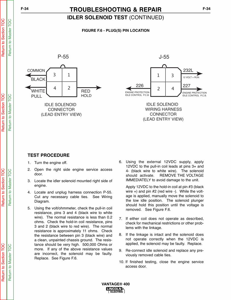
BLACK
RED
P-55 J-55
IDLE SOLENOID CONNECTOR(LEAD ENTRY VIEW)
IDLE SOLENOID WIRING HARNESS CONNECTOR(LEAD ENTRY VIEW)
13
24WHITE
PULL
31
42226
232L
227
ENGINE PROTECTION
IDLE CONTROL P.C.B.
12 VOLT + RUN
ENGINE PROTECTION
IDLE CONTROL P.C.B.
COMMON
HOLD
FIGURE F.6 - PLUG(S) PIN LOCATION
IDLER SOLENOID TEST (CONTINUED)
TEST PROCEDURE
1. Turn the engine off.
2. Open the right side engine service accessdoor.
3. Locate the idler solenoid mounted right side ofengine.
4. Locate and unplug harness connection P-55.Cut any necessary cable ties. See WiringDiagram.
5. Using the volt/ohmmeter, check the pull-in coilresistance, pins 3 and 4 (black wire to whitewire). The normal resistance is less than 0.2ohms. Check the hold-in coil resistance, pins3 and 2 (black wire to red wire). The normalresistance is approximately 11 ohms. Checkthe resistance between pin 3 (black wire) anda clean, unpainted chassis ground. The resis-tance should be very high. 500,000 Ohms ormore. If any of the above resistance valuesare incorrect, the solenoid may be faulty.Replace. See Figure F.6.
6. Using the external 12VDC supply, apply12VDC to the pull-in coil leads at pins 3+ and4- (black wire to white wire). The solenoidshould activate. REMOVE THE VOLTAGEIMMEDIATELY to avoid damage to the unit.
Apply 12VDC to the hold-in coil at pin #3 (blackwire +) and pin #2 (red wire -). While the volt-age is applied, manually move the solenoid tothe low idle position. The solenoid plungershould hold this position until the voltage isremoved. See Figure F.6.
7. If either coil does not operate as described,check for mechanical restrictions or other prob-lems with the linkage.
8. If the linkage is intact and the solenoid doesnot operate correctly when the 12VDC isapplied, the solenoid may be faulty. Replace.
9. Re-connect idle solenoid and replace any pre-viously removed cable ties.
10. If finished testing, close the engine serviceaccess door.
TROUBLESHOOTING & REPAIRF-34 F-34
VANTAGE® 400
Ret
urn
to S
ectio
n TO
CR
etur
n to
Sec
tion
TOC
Ret
urn
to S
ectio
n TO
CR
etur
n to
Sec
tion
TOC
Ret
urn
to M
aste
r TO
CR
etur
n to
Mas
ter
TOC
Ret
urn
to M
aste
r TO
CR
etur
n to
Mas
ter
TOC

Service and repair should be performed by only Lincoln Electric factory trained personnel.Unauthorized repairs performed on this equipment may result in danger to the technicianor machine operator and will invalidate your factory warranty. For your safety and to avoidelectrical shock, please observe all safety notes and precautions detailed throughout thismanual.
If for any reason you do not understand the test procedures or are unable to perform thetest/repairs safely, contact the Lincoln Electric Service Department for electrical trou-bleshooting assistance before you proceed. Call 1-888-935-3877.
TEST DESCRIPTION
This test will determine if the engine alternator is properly charging the battery.
MATERIALS NEEDED
Miscellaneous hand toolsVolt meterWiring Diagram
ENGINE ALTERNATOR TEST
WARNING
TROUBLESHOOTING & REPAIRF-35 F-35
VANTAGE® 400
Ret
urn
to S
ectio
n TO
CR
etur
n to
Sec
tion
TOC
Ret
urn
to S
ectio
n TO
CR
etur
n to
Sec
tion
TOC
Ret
urn
to M
aste
r TO
CR
etur
n to
Mas
ter
TOC
Ret
urn
to M
aste
r TO
CR
etur
n to
Mas
ter
TOC
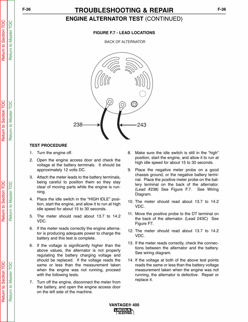
243238
BACK OF ALTERNATOR
FIGURE F.7 - LEAD LOCATIONS
ENGINE ALTERNATOR TEST (CONTINUED)
TEST PROCEDURE
1. Turn the engine off.
2. Open the engine access door and check thevoltage at the battery terminals. It should beapproximately 12 volts DC.
3. Attach the meter leads to the battery terminals,being careful to position them so they stayclear of moving parts while the engine is run-ning.
4. Place the idle switch in the “HIGH IDLE” posi-tion, start the engine, and allow it to run at highidle speed for about 15 to 30 seconds.
5. The meter should read about 13.7 to 14.2VDC.
6. If the meter reads correctly the engine alterna-tor is producing adequate power to charge thebattery and this test is complete.
6. If the voltage is significantly higher than theabove values, the alternator is not properlyregulating the battery charging voltage andshould be replaced. If the voltage reads thesame or less than the measurement takenwhen the engine was not running, proceedwith the following tests.
7. Turn off the engine, disconnect the meter fromthe battery, and open the engine access dooron the left side of the machine.
8. Make sure the idle switch is still in the “high”position, start the engine, and allow it to run athigh idle speed for about 15 to 30 seconds.
9. Place the negative meter probe on a goodchassis ground, or the negative battery termi-nal. Place the positive meter probe on the bat-tery terminal on the back of the alternator.(Lead #238) See Figure F.7. See WiringDiagram.
10. The meter should read about 13.7 to 14.2VDC.
11. Move the positive probe to the DT terminal onthe back of the alternator. (Lead 243C) SeeFigure F7.
12. The meter should read about 13.7 to 14.2VDC.
13. If the meter reads correctly, check the connec-tions between the alternator and the battery.See wiring diagram.
14. If the voltage at both of the above test pointsreads the same or less than the battery voltagemeasurement taken when the engine was notrunning, the alternator is defective. Repair orreplace it.
TROUBLESHOOTING & REPAIRF-36 F-36
VANTAGE® 400
Ret
urn
to S
ectio
n TO
CR
etur
n to
Sec
tion
TOC
Ret
urn
to S
ectio
n TO
CR
etur
n to
Sec
tion
TOC
Ret
urn
to M
aste
r TO
CR
etur
n to
Mas
ter
TOC
Ret
urn
to M
aste
r TO
CR
etur
n to
Mas
ter
TOC

Service and repair should be performed by only Lincoln Electric factory trained personnel.Unauthorized repairs performed on this equipment may result in danger to the technicianor machine operator and will invalidate your factory warranty. For your safety and to avoidelectrical shock, please observe all safety notes and precautions detailed throughout thismanual.
If for any reason you do not understand the test procedures or are unable to perform thetest/repairs safely, contact the Lincoln Electric Service Department for electrical trou-bleshooting assistance before you proceed. Call 1-888-935-3877.
DESCRIPTION
This procedure provides guidance in testing and maintaining the brush and slip ring sys-tem.
MATERIALS NEEDED
Volt/OhmmeterMiscellaneous hand tools500 or 600 grit emery cloth180 grit sand paper
BRUSH AND SLIP RING SERVICE PROCEDURE
WARNING
TROUBLESHOOTING & REPAIRF-37 F-37
VANTAGE® 400
Ret
urn
to S
ectio
n TO
CR
etur
n to
Sec
tion
TOC
Ret
urn
to S
ectio
n TO
CR
etur
n to
Sec
tion
TOC
Ret
urn
to M
aste
r TO
CR
etur
n to
Mas
ter
TOC
Ret
urn
to M
aste
r TO
CR
etur
n to
Mas
ter
TOC
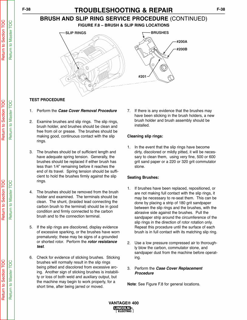
BRUSHESSLIP RINGS
#200A
#200B
#201
FIGURE F.8 – BRUSH & SLIP RING LOCATIONS
BRUSH AND SLIP RING SERVICE PROCEDURE (CONTINUED)
TEST PROCEDURE
1. Perform the Case Cover Removal Procedure
2. Examine brushes and slip rings. The slip rings,brush holder, and brushes should be clean andfree from oil or grease. The brushes should bemaking good, continuous contact with the sliprings.
3. The brushes should be of sufficient length andhave adequate spring tension. Generally, thebrushes should be replaced if either brush hasless than 1/4” remaining before it reaches theend of its travel. Spring tension should be suffi-cient to hold the brushes firmly against the sliprings.
4. The brushes should be removed from the brushholder and examined. The terminals should beclean. The shunt, (braided lead connecting thecarbon brush to the terminal) should be in goodcondition and firmly connected to the carbonbrush and to the connection terminal.
5. If the slip rings are discolored, display evidenceof excessive sparking, or the brushes have wornprematurely; these may be signs of a groundedor shorted rotor. Perform the rotor resistance
test.
6. Check for evidence of sticking brushes. Stickingbrushes will normally result in the slip ringsbeing pitted and discolored from excessive arc-ing. Another sign of sticking brushes is instabili-ty or loss of both weld and auxiliary output, butthe machine may begin to work properly, for ashort time, after being jarred or moved.
7. If there is any evidence that the brushes mayhave been sticking in the brush holders, a newbrush holder and brush assembly should beinstalled.
Cleaning slip rings:
1. In the event that the slip rings have becomedirty, discolored or mildly pitted, it will be neces-sary to clean them, using very fine, 500 or 600grit sand paper or a 220 or 320 grit commutatorstone.
Seating Brushes:
1. If brushes have been replaced, repositioned, orare not making full contact with the slip rings, itmay be necessary to re-seat them. This can bedone by placing a strip of 180 grit sandpaperbetween the slip rings and the brushes, with theabrasive side against the brushes. Pull thesandpaper strip around the circumference of theslip rings in the direction of rotor rotation only.Repeat this procedure until the surface of eachbrush is in full contact with its matching slip ring.
2. Use a low pressure compressed air to thorough-ly blow the carbon, commutator stone, andsandpaper dust from the machine before operat-ing.
3. Perform the Case Cover Replacement
Procedure
Note: See Figure F.8 for general locations.
TROUBLESHOOTING & REPAIRF-38 F-38
VANTAGE® 400
Ret
urn
to S
ectio
n TO
CR
etur
n to
Sec
tion
TOC
Ret
urn
to S
ectio
n TO
CR
etur
n to
Sec
tion
TOC
Ret
urn
to M
aste
r TO
CR
etur
n to
Mas
ter
TOC
Ret
urn
to M
aste
r TO
CR
etur
n to
Mas
ter
TOC

Service and repair should be performed by only Lincoln Electric factory trained personnel.Unauthorized repairs performed on this equipment may result in danger to the technicianor machine operator and will invalidate your factory warranty. For your safety and to avoidelectrical shock, please observe all safety notes and precautions detailed throughout thismanual.
If for any reason you do not understand the test procedures or are unable to perform thetest/repairs safely, contact the Lincoln Electric Service Department for electrical trou-bleshooting assistance before you proceed. Call 1-888-935-3877.
TEST DESCRIPTION
This test will determine if the rotor winding is open, shorted, or grounded.
MATERIALS NEEDED
Miscellaneous hand toolsOhmmeter Analog type meter required for dynamic resistance test.)Wiring Diagram
ROTOR RESISTANCE AND GROUND TEST (STATIC)
WARNING
TROUBLESHOOTING & REPAIRF-39 F-39
VANTAGE® 400
Ret
urn
to S
ectio
n TO
CR
etur
n to
Sec
tion
TOC
Ret
urn
to S
ectio
n TO
CR
etur
n to
Sec
tion
TOC
Ret
urn
to M
aste
r TO
CR
etur
n to
Mas
ter
TOC
Ret
urn
to M
aste
r TO
CR
etur
n to
Mas
ter
TOC

BRUSHESSLIP RINGS#200A
#200B
#201
-
+
FIGURE F.9 - ROTOR BRUSH LEADS
ROTOR RESISTANCE AND GROUND TEST (STATIC) (CONTINUED)
TEST PROCEDURE
1. Turn the engine off.
2. Perform the Case Cover Removal procedure.
3. Locate and label the leads from the rotor brushholder assembly. See Figure F.9. Using theneedle nose pliers, remove the leads. This willelectrically isolate the rotor windings.
4. Using the ohmmeter, check the rotor windingresistance across the slip rings. See FigureF.9. Normal resistance is approximately 25ohm, at 77º F. (25º C.).
5. Measure the resistance to ground. Place onemeter probe on either of the slip rings. Placethe other probe on any good unpainted chassisground. The resistance should be very high, atleast 500,000 (500k) ohms.
6. If the test does not meet the resistance speci-fications, then the rotor may be faulty andshould be replaced.
7. If this test meets the resistance specifications,continue testing using the dynamic rotor resis-tance and ground test.
TROUBLESHOOTING & REPAIRF-40 F-40
VANTAGE® 400
Ret
urn
to S
ectio
n TO
CR
etur
n to
Sec
tion
TOC
Ret
urn
to S
ectio
n TO
CR
etur
n to
Sec
tion
TOC
Ret
urn
to M
aste
r TO
CR
etur
n to
Mas
ter
TOC
Ret
urn
to M
aste
r TO
CR
etur
n to
Mas
ter
TOC

Service and repair should be performed by only Lincoln Electric factory trained personnel.Unauthorized repairs performed on this equipment may result in danger to the technicianor machine operator and will invalidate your factory warranty. For your safety and to avoidelectrical shock, please observe all safety notes and precautions detailed throughout thismanual.
If for any reason you do not understand the test procedures or are unable to perform thetest/repairs safely, contact the Lincoln Electric Service Department for electrical trou-bleshooting assistance before you proceed. Call 1-888-935-3877.
DESCRIPTION
This test checks for faults in the rotor winding, while these windings are being stressed bythe mechanical forces encountered during normal operation.
MATERIALS NEEDED
Miscellaneous hand toolsOhmmeter Analog type meter required for dynamic resistance test.)Wiring Diagram
Note: This test is best performed with a good quality analog type ohmmeter. Many digi-tal meters will not provide stable or accurate Resistance readings while the rotor is spin-ning.
ROTOR RESISTANCE AND GROUND TEST (DYNAMIC)(Also referred to as flying resistance test)
WARNING
TROUBLESHOOTING & REPAIRF-41 F-41
VANTAGE® 400
Ret
urn
to S
ectio
n TO
CR
etur
n to
Sec
tion
TOC
Ret
urn
to S
ectio
n TO
CR
etur
n to
Sec
tion
TOC
Ret
urn
to M
aste
r TO
CR
etur
n to
Mas
ter
TOC
Ret
urn
to M
aste
r TO
CR
etur
n to
Mas
ter
TOC
ROTOR RESISTANCE AND GROUND TEST (DYNAMIC) (CONTINUED)
TEST PROCEDURE
This test requires that the brushes and slip ringsare clean, in good condition, and are properlyseated.
1. Perform the brush and slip ring service
procedure if necessary.
2. Insulate the lead wires that had been discon-nected from the brushes during the staticrotor resistance test. Position and securethem so they cannot become damaged by thespinning rotor.
3. Securely attach the ohmmeter leads to thebrush terminals. Use clips or terminals toattach the leads BEFORE starting the engine.
4. Start the engine and run it at high idle speed(1860-1890 RPM). The resistance shouldread approximately 25Ω at 77ºF (25º C.)
4. Shut off engine, and move one of the ohmme-ter leads to a good clean chassis ground.
5. Restart the engine and run it at high idlespeed (1860-1890 RPM). The resistanceshould be very high, at least 500,000 (500k)ohms.
6. If the resistance readings differ significantlyfrom the values indicated, re-check the brush-es and the brush spring tension. If the brush-es and slip rings are good, replace the rotor.
7. If all testing is finished, perform the Case
Cover Replacement procedure.
*NOTE: The resistance of the windings willchange with temperature. Higher temperatureswill produce higher resistance, and lower temper-atures will produce lower resistance.
TROUBLESHOOTING & REPAIRF-42 F-42
VANTAGE® 400
Ret
urn
to S
ectio
n TO
CR
etur
n to
Sec
tion
TOC
Ret
urn
to S
ectio
n TO
CR
etur
n to
Sec
tion
TOC
Ret
urn
to M
aste
r TO
CR
etur
n to
Mas
ter
TOC
Ret
urn
to M
aste
r TO
CR
etur
n to
Mas
ter
TOC

Service and repair should be performed by only Lincoln Electric factory trained personnel.Unauthorized repairs performed on this equipment may result in danger to the technicianor machine operator and will invalidate your factory warranty. For your safety and to avoidelectrical shock, please observe all safety notes and precautions detailed throughout thismanual.
If for any reason you do not understand the test procedures or are unable to perform thetest/repairs safely, contact the Lincoln Electric Service Department for electrical trou-bleshooting assistance before you proceed. Call 1-888-935-3877.
TEST DESCRIPTION
This test will determine if the rotor winding is operating at normal charge.
MATERIALS NEEDED
Miscellaneous hand toolsVoltmeterWiring Diagram
ROTOR VOLTAGE TEST
WARNING
TROUBLESHOOTING & REPAIRF-43 F-43
VANTAGE® 400
Ret
urn
to S
ectio
n TO
CR
etur
n to
Sec
tion
TOC
Ret
urn
to S
ectio
n TO
CR
etur
n to
Sec
tion
TOC
Ret
urn
to M
aste
r TO
CR
etur
n to
Mas
ter
TOC
Ret
urn
to M
aste
r TO
CR
etur
n to
Mas
ter
TOC

BRUSHESSLIP RINGS
#200A
#200B
#201
-
+
FIGURE F.10 - LEAD LOCATIONS
ROTOR VOLTAGE TEST (CONTINUED)
TEST PROCEDURE
1. Perform the Case Cover Removal procedure.
2. Connect the voltmeter probes to the brush ter-minals. See Figure F.10. See the wiring dia-gram.
3. Set the RUN/STOP switch to “RUN” and theIDLE switch to “HIGH”. Start the engine andallow the RPM to stabilize for about 15 to 30seconds.
The meter should read 145 to 175 VDC.
4. Set the RUN/STOP switch to “STOP”
5. If the meter reading is normal, this test is com-plete.
6. If the voltage measures zero or very near zero,the rotor flashing circuit may be faulty or therotor may be shorted.
7. Perform the Rotor Resistance and Ground
Test and the Flashing Voltage Test.
8. If voltage is higher than 175 VDC, the engineRPM may be too high, or there may be voltageintrusion from one of the higher voltage statorwindings to the stator exciter winding. Performthe Engine Throttle Adjustment Test, andthe Stator Short Circuit and Ground Test.
9. If the voltage is lower than 145, but higherthan 120, the engine RPM may be too low, orthere may be problems in the windings or otherexciter circuit components or connections.Perform the Engine Throttle Adjustment
Test, and then perform the testing describedbelow, under the heading “If the voltage mea-
sures about 3 to 5 VDC”
TROUBLESHOOTING & REPAIRF-44 F-44
VANTAGE® 400
Ret
urn
to S
ectio
n TO
CR
etur
n to
Sec
tion
TOC
Ret
urn
to S
ectio
n TO
CR
etur
n to
Sec
tion
TOC
Ret
urn
to M
aste
r TO
CR
etur
n to
Mas
ter
TOC
Ret
urn
to M
aste
r TO
CR
etur
n to
Mas
ter
TOC
ROTOR VOLTAGE TEST (CONTINUED)
10. If the meter reading indicates battery volt-age, about 12 to 14 VDC, the rotor may beopen, or the brushes may be faulty or not mak-ing proper contact with the slip rings. Performthe Rotor Resistance Test, and Brush and
Slip Ring Service Procedure.
11. If the voltage measures about 3 to 5 VDC,the generator is not building-up to normal out-put even though the flashing circuit appears tobe functioning normally. This condition couldbe caused by one of several failed compo-nents or connections. Continue with the fol-lowing test.
12. Check the field bridge rectifier, and capacitor;also check the wiring and terminals connectingthem. See the wiring diagram.
13. Perform the Rotor Resistance Test.
14. Perform the Stator Short Circuit and Ground
Test.
15. When the Stator short circuit and ground testhas been completed, reconnect leads 6 and5H to the field bridge rectifier, (D3). All otherstator leads should remain disconnected andisolated at this time.
16. Be sure that there are no leads of any kindacross any of the stator windings, except the6A - 5H winding. Examine stator wiring fordamage, pinched leads, chafed insulation, etc.If necessary, disconnect and isolate the statoroutput leads as close to the starter as possible.See wiring diagram.
17. All of these disconnected leads should be insu-lated, and/or positioned so they cannot comein contact with any other wiring or chassisground and cannot be damaged by movingparts when the engine is running.
18. Re-start the machine and measure the rotorvoltage.
19. If rotor voltage continues to read significantlylower than 120 VDC, the Stator is probablydefective and should be replaced.
Note: The field bridge rectifier and field capacitormay appear to function normally when tested inde-pendently, but may malfunction when placed underthe stress or normal operation. For this reason, Itis recommended that the bridge rectifier and thecapacitor be replaced with known good compo-nents before replacing the stator.
TROUBLESHOOTING & REPAIRF-45 F-45
VANTAGE® 400
Ret
urn
to S
ectio
n TO
CR
etur
n to
Sec
tion
TOC
Ret
urn
to S
ectio
n TO
CR
etur
n to
Sec
tion
TOC
Ret
urn
to M
aste
r TO
CR
etur
n to
Mas
ter
TOC
Ret
urn
to M
aste
r TO
CR
etur
n to
Mas
ter
TOC

NOTESF-46 F-46
VANTAGE® 400
Ret
urn
to S
ectio
n TO
CR
etur
n to
Sec
tion
TOC
Ret
urn
to S
ectio
n TO
CR
etur
n to
Sec
tion
TOC
Ret
urn
to M
aste
r TO
CR
etur
n to
Mas
ter
TOC
Ret
urn
to M
aste
r TO
CR
etur
n to
Mas
ter
TOC
Service and repair should be performed by only Lincoln Electric factory trained personnel.Unauthorized repairs performed on this equipment may result in danger to the technicianor machine operator and will invalidate your factory warranty. For your safety and to avoidelectrical shock, please observe all safety notes and precautions detailed throughout thismanual.
If for any reason you do not understand the test procedures or are unable to perform thetest/repairs safely, contact the Lincoln Electric Service Department for electrical trou-bleshooting assistance before you proceed. Call 1-888-935-3877.
TEST DESCRIPTION
This test checks the flashing voltage with the engine stopped, by simulating a running con-dition.
MATERIALS NEEDED
Miscellaneous hand toolsVoltmeterWiring Diagram
FLASHING VOLTAGE TEST(Engine Not Running)
WARNING
TROUBLESHOOTING & REPAIRF-47 F-47
VANTAGE® 400
Ret
urn
to S
ectio
n TO
CR
etur
n to
Sec
tion
TOC
Ret
urn
to S
ectio
n TO
CR
etur
n to
Sec
tion
TOC
Ret
urn
to M
aste
r TO
CR
etur
n to
Mas
ter
TOC
Ret
urn
to M
aste
r TO
CR
etur
n to
Mas
ter
TOC

FLASHING VOLTAGE TEST (CONTINUED)
TEST PROCEDURE
1. Perform the Case Cover Removal
Procedure.
2. Make sure that the battery is fully chargedand in good condition, and the battery con-nections are clean and tight.
3. Remove leads 234 and 235 from the oil pres-sure switch. Insulate or position the lead so itcannot come in contact with chassis groundor any other wiring. See Wiring Diagram.
NOTE: Disconnecting leads 234 and 235 bypassthe oil-pressure switch and simulates a runningengine.
4. Place the RUN/STOP switch in the “RUN”position. (The engine protection light shouldremain off.)
5. Connect the voltmeter probes to brush ter-minals.
6. Measure the voltage; it should read about 3 to5 VDC.
7. Set the RUN/STOP switch to the “STOP”position.
8. If the meter reads normal voltage of 3 to 5VDC, this test is complete.
9. If the meter reading indicates battery voltage,about 12 to 14 VDC, The rotor may be open,or the brushes may be faulty or not makingproper contact with the slip rings.
10. Perform the Rotor Resistance Test.Perform the Brush and Slip Ring Service
Procedure.
11. If the voltage measures zero or very nearzero; this condition could be caused by a poorconnection or a defective component in theflashing circuit, or a shorted rotor winding.
12. Perform the Rotor Resistance Test.
11. Refer to the wiring diagram, pull plug P-23from the control PC board and inspect eachterminal. Make sure that all terminals both onthe board and in the plug are clean and ingood condition, and that the pins are securelycrimped to the flex leads. Perform the follow-ing additional test.
13. Switch the RUN/STOP switch to the “RUN”position.
14. Use a voltmeter to check for the presents ofabout 12VDC, battery voltage, at the followinglocations on the engine protection/ idle controlp.c.b.
(-) Lead #5S (B1) to (+) Lead #232 (J31-1)
(-) Lead #5S (B1) to (+) Lead #232F (J31-2)
(-) Lead #5S (B1) to (+) Lead #200 (J33-5)
NOTE: Lead #232 supplies 12VDC battery volt-age to the engine protection PC board wheneverthe run/stop switch is in the run position.
Lead #200 supplies DC flashing voltage from thecontrol PC board to the positive slip ring through.
15. If battery voltage is present at all of theabove points; check the top groundingstud on inside left case from and lead #5H,also check leads #200, #200B, R3. Makesure all terminals are crimped tightly tothe flex leads and arc free of corrosion.
TROUBLESHOOTING & REPAIRF-48 F-48
VANTAGE® 400
Ret
urn
to S
ectio
n TO
CR
etur
n to
Sec
tion
TOC
Ret
urn
to S
ectio
n TO
CR
etur
n to
Sec
tion
TOC
Ret
urn
to M
aste
r TO
CR
etur
n to
Mas
ter
TOC
Ret
urn
to M
aste
r TO
CR
etur
n to
Mas
ter
TOC

FLASHING VOLTAGE TEST (CONTINUED)
16. If battery voltage is present at leads #232 and#232F, but not present at leads #200 Theengine protection / idle P.C.B. board is proba-bly defective. Replace.
17. If battery voltage is present at lead #232, butnot present at leads #232F or #200 check theengine protection wiring per the wiring dia-gram.
18. If battery voltage is not present at lead #232,check wiring per wiring diagram, and checkthe run/stop switch. Also check the groundPC board chassis ground wire, lead #5K andthe stud where it connects to the chassis.
19. Set the RUN/STOP switch to the “STOP”position.
20. Re-connect lead #234 to the oil pressureswitch.
21. If testing is completed, perform the Case
Cover Replacement procedure.
TROUBLESHOOTING & REPAIRF-49 F-49
VANTAGE® 400
Ret
urn
to S
ectio
n TO
CR
etur
n to
Sec
tion
TOC
Ret
urn
to S
ectio
n TO
CR
etur
n to
Sec
tion
TOC
Ret
urn
to M
aste
r TO
CR
etur
n to
Mas
ter
TOC
Ret
urn
to M
aste
r TO
CR
etur
n to
Mas
ter
TOC

NOTESF-50 F-50
VANTAGE® 400
Ret
urn
to S
ectio
n TO
CR
etur
n to
Sec
tion
TOC
Ret
urn
to S
ectio
n TO
CR
etur
n to
Sec
tion
TOC
Ret
urn
to M
aste
r TO
CR
etur
n to
Mas
ter
TOC
Ret
urn
to M
aste
r TO
CR
etur
n to
Mas
ter
TOC

Service and repair should be performed by only Lincoln Electric factory trained personnel.Unauthorized repairs performed on this equipment may result in danger to the technicianor machine operator and will invalidate your factory warranty. For your safety and to avoidelectrical shock, please observe all safety notes and precautions detailed throughout thismanual.
If for any reason you do not understand the test procedures or are unable to perform thetest/repairs safely, contact the Lincoln Electric Service Department for electrical trou-bleshooting assistance before you proceed. Call 1-888-935-3877.
TEST DESCRIPTION
This test will determine if the stator is able to produce correct voltage from of its windings.It will only yield meaning data if the engine high idle speed is correct, (1860 to 1890 RPM),and approximately 160 VDC is present across the rotor slip rings.
NOTE: The slip ring voltage will most likely be correct if at least one of the AC output volt-ages is correct.
MATERIALS NEEDED
Miscellaneous hand toolsVoltmeterTest pins
STATOR VOLTAGE TESTS
WARNING
TROUBLESHOOTING & REPAIRF-51 F-51
VANTAGE® 400
Ret
urn
to S
ectio
n TO
CR
etur
n to
Sec
tion
TOC
Ret
urn
to S
ectio
n TO
CR
etur
n to
Sec
tion
TOC
Ret
urn
to M
aste
r TO
CR
etur
n to
Mas
ter
TOC
Ret
urn
to M
aste
r TO
CR
etur
n to
Mas
ter
TOC

FIGURE F.11 RECEPTACLE LEAD LOCATIONS (TYPICAL)
STATOR VOLTAGE TESTS (CONTINUED)
TEST PROCEDURE
1. Perform the Case Cover Removal procedure.
NOTE: Voltage tests of the 120 and 120/240 VACreceptacles can be performed by placing the meterprobes directly into the appropriate connection slotsin the front of the receptacles rather than testing atthe lead connections described below. If the meterprobes are not long enough to make contact with theconductors inside the receptacles, test pins may beused.
To test the 120 VAC auxiliary winding:
1. Connect the volt/ohmmeter probes to either 120VAC receptacle as follows.
2. For the upper receptacle, place the probes direct-ly into receptacle, or connect to leads #3D and#5A. See Figure F.11. See wiring diagram.
For the lower receptacle, place the probes direct-ly into the receptacle, or connect to leads #6Eand 5B. See Figure F.11. See wiring diagram.
3. Start the engine and run it at high idle (1860-1890RPM).
4. Check the AC voltage reading. It should readbetween 115 and 132 VAC.
To test the 240 VAC auxiliary winding:
1. Connect the meter probes to leads #6F and #3Ewhere they connect to the 120/240VAC recepta-cle, or insert the probes into the 240 VAC con-nection slots in the front of the receptacle. SeeFigure F.11. See wiring diagram.
2. Start the engine and run it at high idle (1860-1890RPM).
3. Check the AC voltage reading. It should readbetween 230 and 264 VAC.
4. If these voltage readings are not within the spec-ified limits, check for tripped or defective circuitbreakers, loose connections, or broken wiresbetween the test points and the stator windings.If there are no wiring problems, and the circuitbreakers are not tripped or defective, the stator isdefective and should be replaced.
TROUBLESHOOTING & REPAIRF-52 F-52
VANTAGE® 400
AMPHENOL 1
KEY
E
C
D
AB
L K J
M N
F GH
I
CONTACTOR
CONTROL
L4
GROUND
120 VAC FOR WIRE FEEDER
40 VAC FOR WIRE FEEDER
21 WORK SENSE
2 TIMES THRU FERRITE
LEADS 75A, 76A, & 77A
REMOTE
CONTROL
Ret
urn
to S
ectio
n TO
CR
etur
n to
Sec
tion
TOC
Ret
urn
to S
ectio
n TO
CR
etur
n to
Sec
tion
TOC
Ret
urn
to M
aste
r TO
CR
etur
n to
Mas
ter
TOC
Ret
urn
to M
aste
r TO
CR
etur
n to
Mas
ter
TOC

FIGURE F.12 - RECTIFIER BRIDGE DETAIL
STATOR VOLTAGE TESTS (CONTINUED)
To test the 120 VAC wire feeder supply:
NOTE: The wire feeder AC voltage supply testsrequire that the meter probes be inserted into theAmphenol connection cavities. Care should betaken to avoid damaging or expanding the termi-nals when inserting the probes.
NOTE: The 120 VAC power supplied to the 14 pinAmphenol connector originates from the samewinding that supplies the 120 VAC receptacles. Ifthe machine has previously passed 120VAC auxil-iary winding test, this test can only reveal problemsin connections or components between theAmphenol and the stator winding.
1. Connect the voltmeter probes to pins “A” (lead#32) and “J” (lead #31) of the 14 pin Amphenol.See figure #3 and wiring diagram.
2. Start the engine and run it at high idle (1860 to1890 RPM).
3. The AC voltage reading should be between115 and 132 VAC.
4. If these voltage readings are not within specifi-cations, check for a tripped or defective circuitbreaker, faulty connections, or broken wiresbetween the test points and the stator wind-ings. See wiring diagram.
TROUBLESHOOTING & REPAIRF-53 F-53
VANTAGE® 400
Ret
urn
to S
ectio
n TO
CR
etur
n to
Sec
tion
TOC
Ret
urn
to S
ectio
n TO
CR
etur
n to
Sec
tion
TOC
Ret
urn
to M
aste
r TO
CR
etur
n to
Mas
ter
TOC
Ret
urn
to M
aste
r TO
CR
etur
n to
Mas
ter
TOC
STATOR VOLTAGE TESTS (CONTINUED)
To test the 42 VAC wire feeder winding:
1. Connect the voltmeter probes to pins “I” (lead41A) and “K” (lead #42A) of the 14 pinAmphenol. See Figure F.11.
2. Start the engine and run it at high idle (1860 to1890 RPM).
3. The AC voltage reading should be between 40and 50 VAC.
4. If these voltage readings are not within thespecified limits, check for a tripped or defectivecircuit breakers, loose connections, or brokenwires between the test points and the statorwindings. If there are no wiring problems, andthe circuit breakers are not tripped or defec-tive, the stator is defective and should bereplaced.
To test the three-phase weld winding:
1. Locate weld winding leads W1, W2, and W3where they connect to the three-phase outputbridge rectifier. See Figure F.12. See wiringdiagram.
2. Start the engine and run it at high idle (1860 to1890 RPM).
3. Check for about 60 to 65 VAC from leads W1to W2, W2 to W3, and W1 to W3.
4. If these voltage readings are not within thespecified limits, check for loose connections orbroken wires between the test points and thestator windings. If there are no wiring prob-lems, the stator is defective and should bereplaced.
* These values are maximum for a cold machine.
TROUBLESHOOTING & REPAIRF-54 F-54
VANTAGE® 400
Ret
urn
to S
ectio
n TO
CR
etur
n to
Sec
tion
TOC
Ret
urn
to S
ectio
n TO
CR
etur
n to
Sec
tion
TOC
Ret
urn
to M
aste
r TO
CR
etur
n to
Mas
ter
TOC
Ret
urn
to M
aste
r TO
CR
etur
n to
Mas
ter
TOC

Service and repair should be performed by only Lincoln Electric factory trained personnel.Unauthorized repairs performed on this equipment may result in danger to the technicianor machine operator and will invalidate your factory warranty. For your safety and to avoidelectrical shock, please observe all safety notes and precautions detailed throughout thismanual.
If for any reason you do not understand the test procedures or are unable to perform thetest/repairs safely, contact the Lincoln Electric Service Department for electrical trou-bleshooting assistance before you proceed. Call 1-888-935-3877.
TEST DESCRIPTION
This test will determine if there are undesirable electrical connections between the statorwindings and chassis ground, or between individual windings within the stator.
This test should be performed if flashing voltage is present at the rotor slip rings, Rotorresistance, field bridge rectifier, field capacitor and all associated wiring are proven to begood, but the stator output voltage fails to build-up to normal levels, or is too high in oneor more, but not all, of the windings.
MATERIALS NEEDED
Miscellaneous hand toolsOhm meter
STATOR SHORT CIRCUIT & GROUND TEST
WARNING
TROUBLESHOOTING & REPAIRF-55 F-55
VANTAGE® 400
Ret
urn
to S
ectio
n TO
CR
etur
n to
Sec
tion
TOC
Ret
urn
to S
ectio
n TO
CR
etur
n to
Sec
tion
TOC
Ret
urn
to M
aste
r TO
CR
etur
n to
Mas
ter
TOC
Ret
urn
to M
aste
r TO
CR
etur
n to
Mas
ter
TOC
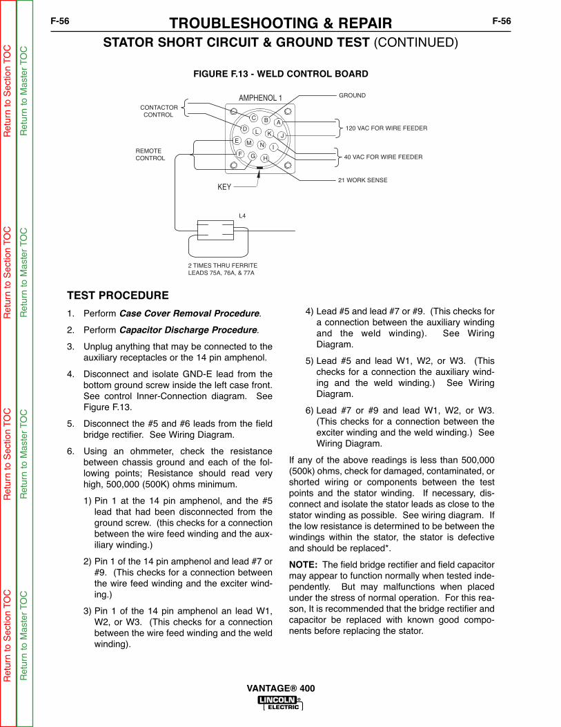
FIGURE F.13 - WELD CONTROL BOARD
STATOR SHORT CIRCUIT & GROUND TEST (CONTINUED)
TEST PROCEDURE
1. Perform Case Cover Removal Procedure.
2. Perform Capacitor Discharge Procedure.
3. Unplug anything that may be connected to theauxiliary receptacles or the 14 pin amphenol.
4. Disconnect and isolate GND-E lead from thebottom ground screw inside the left case front.See control Inner-Connection diagram. SeeFigure F.13.
5. Disconnect the #5 and #6 leads from the fieldbridge rectifier. See Wiring Diagram.
6. Using an ohmmeter, check the resistancebetween chassis ground and each of the fol-lowing points; Resistance should read veryhigh, 500,000 (500K) ohms minimum.
1) Pin 1 at the 14 pin amphenol, and the #5lead that had been disconnected from theground screw. (this checks for a connectionbetween the wire feed winding and the aux-iliary winding.)
2) Pin 1 of the 14 pin amphenol and lead #7 or#9. (This checks for a connection betweenthe wire feed winding and the exciter wind-ing.)
3) Pin 1 of the 14 pin amphenol an lead W1,W2, or W3. (This checks for a connectionbetween the wire feed winding and the weldwinding).
4) Lead #5 and lead #7 or #9. (This checks fora connection between the auxiliary windingand the weld winding). See WiringDiagram.
5) Lead #5 and lead W1, W2, or W3. (Thischecks for a connection the auxiliary wind-ing and the weld winding.) See WiringDiagram.
6) Lead #7 or #9 and lead W1, W2, or W3.(This checks for a connection between theexciter winding and the weld winding.) SeeWiring Diagram.
If any of the above readings is less than 500,000(500k) ohms, check for damaged, contaminated, orshorted wiring or components between the testpoints and the stator winding. If necessary, dis-connect and isolate the stator leads as close to thestator winding as possible. See wiring diagram. Ifthe low resistance is determined to be between thewindings within the stator, the stator is defectiveand should be replaced*.
NOTE: The field bridge rectifier and field capacitormay appear to function normally when tested inde-pendently. But may malfunctions when placedunder the stress of normal operation. For this rea-son, It is recommended that the bridge rectifier andcapacitor be replaced with known good compo-nents before replacing the stator.
TROUBLESHOOTING & REPAIRF-56 F-56
VANTAGE® 400
AMPHENOL 1
KEY
E
C
D
AB
L K J
M N
F GH
I
CONTACTOR
CONTROL
L4
GROUND
120 VAC FOR WIRE FEEDER
40 VAC FOR WIRE FEEDER
21 WORK SENSE
2 TIMES THRU FERRITE
LEADS 75A, 76A, & 77A
REMOTE
CONTROL
Ret
urn
to S
ectio
n TO
CR
etur
n to
Sec
tion
TOC
Ret
urn
to S
ectio
n TO
CR
etur
n to
Sec
tion
TOC
Ret
urn
to M
aste
r TO
CR
etur
n to
Mas
ter
TOC
Ret
urn
to M
aste
r TO
CR
etur
n to
Mas
ter
TOC

Service and repair should be performed by only Lincoln Electric factory trained personnel.Unauthorized repairs performed on this equipment may result in danger to the technicianor machine operator and will invalidate your factory warranty. For your safety and to avoidelectrical shock, please observe all safety notes and precautions detailed throughout thismanual.
If for any reason you do not understand the test procedures or are unable to perform thetest/repairs safely, contact the Lincoln Electric Service Department for electrical trou-bleshooting assistance before you proceed. Call 1-888-935-3877.
TEST DESCRIPTION
This test will determine if the rectifier is grounded, or if there are any failed diode groups.
NOTE: This test will not be able to detect individual open diodes within a group.
MATERIALS NEEDED
Miscellaneous hand toolsAnalog Ohmmeter or diode tester (For testing diodes)Ohm meter (any type for ground test)
OUTPUT RECTIFIER BRIDGE TEST
WARNING
TROUBLESHOOTING & REPAIRF-57 F-57
VANTAGE® 400
Ret
urn
to S
ectio
n TO
CR
etur
n to
Sec
tion
TOC
Ret
urn
to S
ectio
n TO
CR
etur
n to
Sec
tion
TOC
Ret
urn
to M
aste
r TO
CR
etur
n to
Mas
ter
TOC
Ret
urn
to M
aste
r TO
CR
etur
n to
Mas
ter
TOC
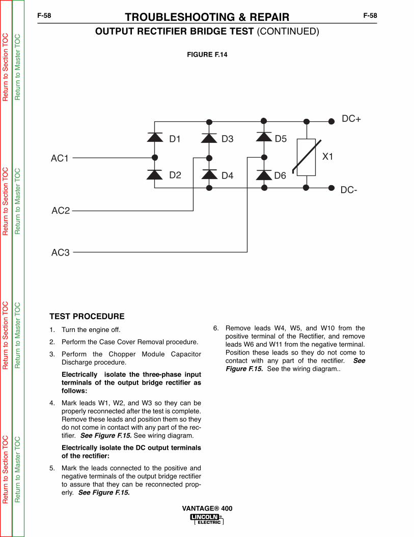
FIGURE F.14
OUTPUT RECTIFIER BRIDGE TEST (CONTINUED)
TEST PROCEDURE
1. Turn the engine off.
2. Perform the Case Cover Removal procedure.
3. Perform the Chopper Module CapacitorDischarge procedure.
Electrically isolate the three-phase inputterminals of the output bridge rectifier asfollows:
4. Mark leads W1, W2, and W3 so they can beproperly reconnected after the test is complete.Remove these leads and position them so theydo not come in contact with any part of the rec-tifier. See Figure F.15. See wiring diagram.
Electrically isolate the DC output terminalsof the rectifier:
5. Mark the leads connected to the positive andnegative terminals of the output bridge rectifierto assure that they can be reconnected prop-erly. See Figure F.15.
6. Remove leads W4, W5, and W10 from thepositive terminal of the Rectifier, and removeleads W6 and W11 from the negative terminal.Position these leads so they do not come tocontact with any part of the rectifier. See
Figure F.15. See the wiring diagram..
TROUBLESHOOTING & REPAIRF-58 F-58
VANTAGE® 400
X1
DC+
DC-
D5
D6
D3
D4
D1
D2
AC3
AC2
AC1
Ret
urn
to S
ectio
n TO
CR
etur
n to
Sec
tion
TOC
Ret
urn
to S
ectio
n TO
CR
etur
n to
Sec
tion
TOC
Ret
urn
to M
aste
r TO
CR
etur
n to
Mas
ter
TOC
Ret
urn
to M
aste
r TO
CR
etur
n to
Mas
ter
TOC
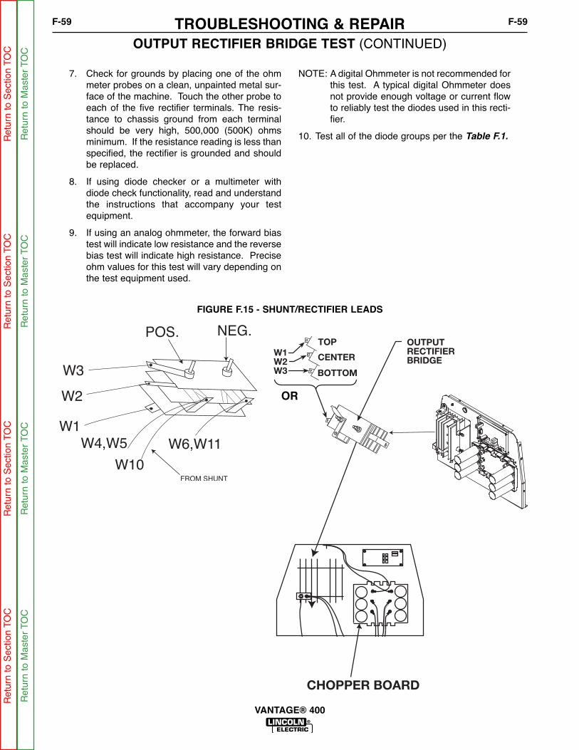
CHOPPER BOARD
W1W2W3
OUTPUT RECTIFIERBRIDGE
TOP
CENTER
BOTTOM
FIGURE F.15 - SHUNT/RECTIFIER LEADS
OUTPUT RECTIFIER BRIDGE TEST (CONTINUED)
7. Check for grounds by placing one of the ohmmeter probes on a clean, unpainted metal sur-face of the machine. Touch the other probe toeach of the five rectifier terminals. The resis-tance to chassis ground from each terminalshould be very high, 500,000 (500K) ohmsminimum. If the resistance reading is less thanspecified, the rectifier is grounded and shouldbe replaced.
8. If using diode checker or a multimeter withdiode check functionality, read and understandthe instructions that accompany your testequipment.
9. If using an analog ohmmeter, the forward biastest will indicate low resistance and the reversebias test will indicate high resistance. Preciseohm values for this test will vary depending onthe test equipment used.
NOTE: A digital Ohmmeter is not recommended forthis test. A typical digital Ohmmeter doesnot provide enough voltage or current flowto reliably test the diodes used in this recti-fier.
10. Test all of the diode groups per the Table F.1.
TROUBLESHOOTING & REPAIRF-59 F-59
VANTAGE® 400
OR
Ret
urn
to S
ectio
n TO
CR
etur
n to
Sec
tion
TOC
Ret
urn
to S
ectio
n TO
CR
etur
n to
Sec
tion
TOC
Ret
urn
to M
aste
r TO
CR
etur
n to
Mas
ter
TOC
Ret
urn
to M
aste
r TO
CR
etur
n to
Mas
ter
TOC

TROUBLESHOOTING & REPAIRF-60 F-60
VANTAGE® 400
(+) Lead (-) LeadDiode Bias
and ExpectedTest Result
AC1 DC(+) FORWARD BIAS(Low Resistance)
AC2 DC(+) FORWARD BIAS(Low Resistance)
AC3 DC(+) FORWARD BIAS(Low Resistance)
DC(-) AC1 FORWARD BIAS(Low Resistance)
DC(-) AC2 FORWARD BIAS(Low Resistance)
DC(-) AC3 FORWARD BIAS(Low Resistance)
AC1 DC(-) REVERSE BIAS(High Resistance)
AC2 DC(-) REVERSE BIAS(High Resistance)
AC3 DC(-) REVERSE BIAS(High Resistance)
DC(+) AC1 REVERSE BIAS(High Resistance)
DC(+) AC2 REVERSE BIAS(High Resistance)
DC(+) AC3 REVERSE BIAS(High Resistance)
11. Reconnect all leads.
12. Perform the Case Cover replacement Procedure.
TABLE F.1 – DIODE TEST TABLE
Test Instrument
Rectifier Term
inal C
on
nectio
ns
Ret
urn
to S
ectio
n TO
CR
etur
n to
Sec
tion
TOC
Ret
urn
to S
ectio
n TO
CR
etur
n to
Sec
tion
TOC
Ret
urn
to M
aste
r TO
CR
etur
n to
Mas
ter
TOC
Ret
urn
to M
aste
r TO
CR
etur
n to
Mas
ter
TOC

Service and repair should be performed by only Lincoln Electric factory trained personnel.Unauthorized repairs performed on this equipment may result in danger to the technicianor machine operator and will invalidate your factory warranty. For your safety and to avoidelectrical shock, please observe all safety notes and precautions detailed throughout thismanual.
If for any reason you do not understand the test procedures or are unable to perform thetest/repairs safely, contact the Lincoln Electric Service Department for electrical trou-bleshooting assistance before you proceed. Call 1-888-935-3877.
DESCRIPTION
This test will help determine if the chopper module is functioning properly, and receivingthe correct input from the output rectifier and control PC board.
This test can only provide meaningful results if the machine is producing normal AC aux-iliary output.
MATERIALS NEEDED
Miscellaneous hand toolsDigital Multi-meterFrequency counter or digital multi-meter with frequency counter function.Wiring diagramControl Inner-Connection diagram
CHOPPER MODULE FUNCTION TEST
WARNING
TROUBLESHOOTING & REPAIRF-61 F-61
VANTAGE® 400
Ret
urn
to S
ectio
n TO
CR
etur
n to
Sec
tion
TOC
Ret
urn
to S
ectio
n TO
CR
etur
n to
Sec
tion
TOC
Ret
urn
to M
aste
r TO
CR
etur
n to
Mas
ter
TOC
Ret
urn
to M
aste
r TO
CR
etur
n to
Mas
ter
TOC

B1
B2
B3 B6
B5
B4
2325
SL302
SL301
HL W9
HL W4
HL W6
SL14SL13
B8
HL W8
HL W5
HL W11
LED1LED1LED4LED4
LED2LED2LED3LED3
L12683-1
LED1 (B1,B2,B3)Chopper Working
LED3 (B4,B5,B6)Chopper Working
LED4PWM Signal
LED2Voltage from Rectifier
FIGURE F.16 - CHOPPER MODULE CONNECTIONS
CHOPPER MODULE FUNCTION TEST (CONTINUED)
TEST PROCEDURE
1. Perform the Case Cover Removal
Procedure.
2. Make sure that there is nothing plugged intoeither of the Amphenol receptacles.
3. Place idle switch in the “HIGH” position.
4. Place the mode switch in the “CC-STICK” posi-tion.
5. Place the Welding Terminal switch in the“REMOTELY CONTROLLED” position.
6. Start the engine and allow it to stabilize at highidle RPM.
7. Check for 80 to 100 VDC at terminals B1- toB2+ and B4- to B5+ of the chopper module.See wiring diagram and figure #1.
8. If the correct DC voltage is not present at ter-minals B1- to B2+ and B4- to B5+, check fordamaged conductors or faulty connectionsbetween the chopper module, the output recti-fier, and the stator weld winding. See FigureF.17. See the wiring diagram. Perform theStator Voltage Tests, and the Output
Rectifier Test.
9. If the correct voltage is present at terminalsB1- to B2+ and B4- to B5+ of the chopper mod-ule, check for DC voltage at the chopper mod-ule terminals B2+ to B3-, and B5+ to B6-, If sig-nificant voltage is present, disconnect leads#23 and #25 from the chopper module PCboard. If voltage is still present, the coppermodule is shorted and should be replaced.
10. If the voltage drops to 0 VDC after the #23 and#25 leads have been disconnected, the controlPC board is driving the chopper module whenit should not be doing so. Reconnect the #23and #25 leads and perform the Weld Control
Board Gate Drive Test.
11. Reconnect leads #23 and #25, and place theWelding Terminal switch in the “WELD TERMI-NALS ON” position.
12. Check for about 58 VDC between ChopperModule Terminals B2+ to B3-, and B5+ to B6and between the welder output terminals. SeeFigure F.16. See the wiring diagram.
TROUBLESHOOTING & REPAIRF-62 F-62
VANTAGE® 400
Ret
urn
to S
ectio
n TO
CR
etur
n to
Sec
tion
TOC
Ret
urn
to S
ectio
n TO
CR
etur
n to
Sec
tion
TOC
Ret
urn
to M
aste
r TO
CR
etur
n to
Mas
ter
TOC
Ret
urn
to M
aste
r TO
CR
etur
n to
Mas
ter
TOC

CHOPPER MODULE FUNCTION TEST (CONTINUED)
TEST PROCEDURE (CONTINUED)
13. If about 58 VDC is present at chopper moduleterminals B2+ to B3-, and B5+ to B6-, but notat the output terminals, there is a problembetween the chopper module and one of theoutput terminals. Check for damaged conduc-tors or faulty connections, on leads W7, W8,W9, and W10. Also check the shunt, thechoke, and the connections at the back of theoutput terminals. See the wiring diagram.
14. If the voltage at terminals B2+ to B3-, and B5+to B6- of the Chopper module is significantlyhigher than 58 VDC, check for an open R4load resistor. See the Control Inner-Connection diagram. Also check for damagedconductors or faulty connections at leads #302and #302. See wiring diagram.
15. If the voltage at terminals B2+ to B3-, and B5+to B6- of the chopper module is very low, or notpresent, use the frequency counter to checkfor the presents of a 20 kHZ PWM signalbetween leads #23 +and #25-, where they con-nect to the chopper module PC board.
16. If the 20 kHz signal is present, the choppermodule is defective. Replace.
17. If the 20 kHz signal is not present, perform theWeld Control Board PWM Gate Signal Test.
18. If the weld control board is producing a PWMgate signal, check th e#23 and #25 leads fordamaged conductors and faulty connectionsbetween the control PC board and the choppermodule.
19. If testing is complete, Perform the Case Cover
Replacement procedure.
TROUBLESHOOTING & REPAIRF-63 F-63
VANTAGE® 400
Ret
urn
to S
ectio
n TO
CR
etur
n to
Sec
tion
TOC
Ret
urn
to S
ectio
n TO
CR
etur
n to
Sec
tion
TOC
Ret
urn
to M
aste
r TO
CR
etur
n to
Mas
ter
TOC
Ret
urn
to M
aste
r TO
CR
etur
n to
Mas
ter
TOC

NOTESF-64 F-64
VANTAGE® 400
Ret
urn
to S
ectio
n TO
CR
etur
n to
Sec
tion
TOC
Ret
urn
to S
ectio
n TO
CR
etur
n to
Sec
tion
TOC
Ret
urn
to M
aste
r TO
CR
etur
n to
Mas
ter
TOC
Ret
urn
to M
aste
r TO
CR
etur
n to
Mas
ter
TOC

Service and repair should be performed by only Lincoln Electric factory trained personnel.Unauthorized repairs performed on this equipment may result in danger to the technicianor machine operator and will invalidate your factory warranty. For your safety and to avoidelectrical shock, please observe all safety notes and precautions detailed throughout thismanual.
If for any reason you do not understand the test procedures or are unable to perform thetest/repairs safely, contact the Lincoln Electric Service Department for electrical trou-bleshooting assistance before you proceed. Call 1-888-935-3877.
TEST DESCRIPTION
This test will help determine if the chopper module is shorted. This test can only detectsome problems in the “Power” section of the module. Problems in some other PC boardcomponents may not be detected.
MATERIALS NEEDED
Miscellaneous hand toolsDigital OhmmeterWiring diagram
CHOPPER MODULE RESISTANCE TEST
WARNING
TROUBLESHOOTING & REPAIRF-65 F-65
VANTAGE® 400
Ret
urn
to S
ectio
n TO
CR
etur
n to
Sec
tion
TOC
Ret
urn
to S
ectio
n TO
CR
etur
n to
Sec
tion
TOC
Ret
urn
to M
aste
r TO
CR
etur
n to
Mas
ter
TOC
Ret
urn
to M
aste
r TO
CR
etur
n to
Mas
ter
TOC

CHOPPER MODULE RESISTANCE TEST (CONTINUED)
TEST PROCEDURE
1. Perform the Case Cover Removal
Procedure.
2. Perform the Capacitor Discharge Procedure.
3. Check that all of the leads connected to thechopper module terminals are clearly markedto facilitate reassembly. Remove all of theleads from the chopper module and positionthem so they do not make electrical contactwith any part of the module. See the wiringdiagram.
4. Use a digital Ohmmeter to test the module perTable F.2.
TROUBLESHOOTING & REPAIRF-66 F-66
VANTAGE® 400
Ret
urn
to S
ectio
n TO
CR
etur
n to
Sec
tion
TOC
Ret
urn
to S
ectio
n TO
CR
etur
n to
Sec
tion
TOC
Ret
urn
to M
aste
r TO
CR
etur
n to
Mas
ter
TOC
Ret
urn
to M
aste
r TO
CR
etur
n to
Mas
ter
TOC
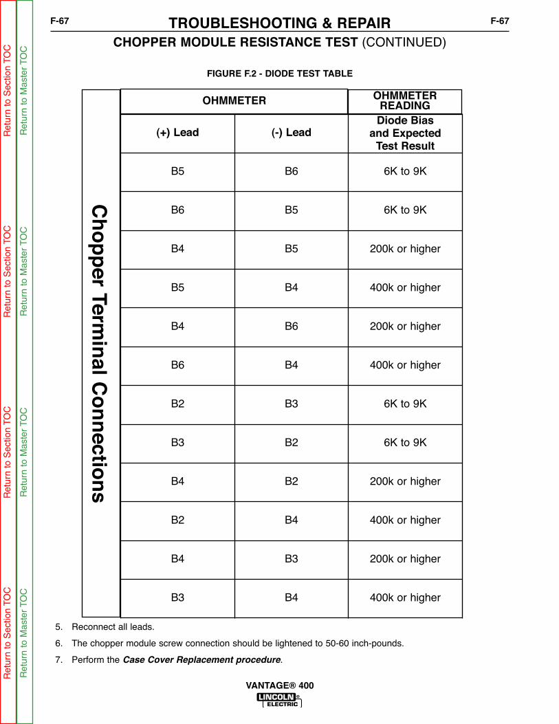
FIGURE F.2 - DIODE TEST TABLE
CHOPPER MODULE RESISTANCE TEST (CONTINUED)TROUBLESHOOTING & REPAIRF-67 F-67
VANTAGE® 400
(+) Lead (-) LeadDiode Bias
and ExpectedTest Result
B5 B6 6K to 9K
B6 B5 6K to 9K
B4 B5 200k or higher
B5 B4 400k or higher
B4 B6 200k or higher
B6 B4 400k or higher
B2 B3 6K to 9K
B3 B2 6K to 9K
B4 B2 200k or higher
B2 B4 400k or higher
B4 B3 200k or higher
B3 B4 400k or higher
OHMMETER OHMMETERREADING
Ch
op
per Term
inal C
on
nectio
ns
5. Reconnect all leads.
6. The chopper module screw connection should be lightened to 50-60 inch-pounds.
7. Perform the Case Cover Replacement procedure.
Ret
urn
to S
ectio
n TO
CR
etur
n to
Sec
tion
TOC
Ret
urn
to S
ectio
n TO
CR
etur
n to
Sec
tion
TOC
Ret
urn
to M
aste
r TO
CR
etur
n to
Mas
ter
TOC
Ret
urn
to M
aste
r TO
CR
etur
n to
Mas
ter
TOC

NOTESF-68 F-68
VANTAGE® 400
Ret
urn
to S
ectio
n TO
CR
etur
n to
Sec
tion
TOC
Ret
urn
to S
ectio
n TO
CR
etur
n to
Sec
tion
TOC
Ret
urn
to M
aste
r TO
CR
etur
n to
Mas
ter
TOC
Ret
urn
to M
aste
r TO
CR
etur
n to
Mas
ter
TOC

Service and repair should be performed by only Lincoln Electric factory trained personnel.Unauthorized repairs performed on this equipment may result in danger to the technicianor machine operator and will invalidate your factory warranty. For your safety and to avoidelectrical shock, please observe all safety notes and precautions detailed throughout thismanual.
If for any reason you do not understand the test procedures or are unable to perform thetest/repairs safely, contact the Lincoln Electric Service Department for electrical trou-bleshooting assistance before you proceed. Call 1-888-935-3877.
DESCRIPTION
This test will determine if the weld control PC board is able to produce the PWM (PulseWidth Modulated) gate signal needed to control the IGBTs (Insulated Gate BipolarTransistor) on the chopper module. This test will also verify that the control PC board canturn the PWM gate signal on and off properly.
MATERIALS NEEDED
Digital Multi-meterFrequency counter, or digital Multi-meter with frequency counter functionWiring DiagramControl Inner-Connection diagram
WELD CONTROL BOARD PWM GATE SIGNAL TEST
WARNING
TROUBLESHOOTING & REPAIRF-69 F-69
VANTAGE® 400
Ret
urn
to S
ectio
n TO
CR
etur
n to
Sec
tion
TOC
Ret
urn
to S
ectio
n TO
CR
etur
n to
Sec
tion
TOC
Ret
urn
to M
aste
r TO
CR
etur
n to
Mas
ter
TOC
Ret
urn
to M
aste
r TO
CR
etur
n to
Mas
ter
TOC

WELD CONTROL BOARD PWM GATE SIGNAL TEST (CONTINUED)
TEST PROCEDURE
1. Perform the Case Cover Removal
Procedure.
2. Unplug any device that may be attached toeither the 6 pin or the 14 pin Amphenol recep-tacles.
3. Place the idle switch in the “HIGH IDLE” posi-tion.
4. Place the mode switch in the “CC-STICK”position.
5. Place the Weld terminals switch in the “WELDTERMINALS ON” position.
6. Start the engine and let it run and stabilize athigh idle RPM.
7. Locate plug P3 on the control PC board. SeeControl Inner-Connection diagram.
8. Use the frequency counter to test for 20kHzPWM gate signal between leads #23+ (P3-10)and #25- (P3-9).
9. If the 20KHz gate signal is present, place theweld terminals switch in the ”REMOTELYCONTROLLED” position. The gate signalshould turn off.
10. If the 20 KHz gate signal responds asdescribed above, this test is complete.
11. If there is no 20 KHz gate signal, test for thepresents of 80 to 100 VDC, at leads 13+ (P3-8) to 14- (P3-16) of the weld control PCboard.
12. If voltage is very low or not present, checkleads #13 and #14 for faulty or damagedwiring or connections between the control PCboard and the chopper module.
13. Test for 80 to 100 VDC at the terminals wherethe #13 and #14 leads connect to the choppermodule. See the wiring diagram. If there isno voltage at the chopper module, performthe chopper module function test.
14. If the 80 to 100 VDC supply voltage is presentat the weld control PC board, but there is noPWM gate signal, check the voltage betweenleads #2+ (P1-4) and #4 (P1-3). See figure#1
The voltage should be about 0 VDC.
15. If about 5 VDC is detected, the welding termi-nal control circuit is open. Check for dam-aged leads for faulty connections at leads #2and #4; also check for a defective welding ter-minal switch. See the wiring diagram.
16. If the PWM signal remains after the weldingterminal switch has been placed in the“REMOTELY CONTROLLED” position, checkthe voltage between leads #2+ (P1-4) and #4-(P1-3) at the control PC board.
17. If the voltage reads 0 or very near 0, Checkfor damaged insulation at leads #2 and #4,also check for a shorted welding terminalswitch, or damaged or contaminatedAmphenol receptacle. See the wiring dia-gram.
18. If the above wiring and components areundamaged and functioning properly, the con-trol PC board is defective and should bereplaced.
19. If the voltage reads about 5 VDC, and thePWM signal remains, the control PC board isdefective and should be replaced.
20. Perform the Case Cover Replacement
Procedure.
TROUBLESHOOTING & REPAIRF-70 F-70
VANTAGE® 400
Ret
urn
to S
ectio
n TO
CR
etur
n to
Sec
tion
TOC
Ret
urn
to S
ectio
n TO
CR
etur
n to
Sec
tion
TOC
Ret
urn
to M
aste
r TO
CR
etur
n to
Mas
ter
TOC
Ret
urn
to M
aste
r TO
CR
etur
n to
Mas
ter
TOC

Service and repair should be performed by only Lincoln Electric factory trained personnel.Unauthorized repairs performed on this equipment may result in danger to the technicianor machine operator and will invalidate your factory warranty. For your safety and to avoidelectrical shock, please observe all safety notes and precautions detailed throughout thismanual.
If for any reason you do not understand the test procedures or are unable to perform thetest/repairs safely, contact the Lincoln Electric Service Department for electrical trou-bleshooting assistance before you proceed. Call 1-888-935-3877.
DESCRIPTION
This test will determine if the weld control PC board is receiving accurate current and volt-age feedback from the weld circuit.
This test will only yield usable information if the machine is producing some weld output.
MATERIALS NEEDED
Digital Multi-meter suitable for accurate readings in both the millivolt and normalweld voltage ranges.Resistive load bankAmmeter, suitable for accurate readings of normal welding current. (Often built intothe load bank.Wiring diagramControl Inner-Connection diagram
WELD CONTROL FEEDBACK TEST
WARNING
TROUBLESHOOTING & REPAIRF-71 F-71
VANTAGE® 400
Ret
urn
to S
ectio
n TO
CR
etur
n to
Sec
tion
TOC
Ret
urn
to S
ectio
n TO
CR
etur
n to
Sec
tion
TOC
Ret
urn
to M
aste
r TO
CR
etur
n to
Mas
ter
TOC
Ret
urn
to M
aste
r TO
CR
etur
n to
Mas
ter
TOC

WELD CONTROL FEEDBACK TEST (CONTINUED)
TEST PROCEDURE
1. Place the idle switch in the “HIGH IDLE” posi-tion.
2. Place the mode switch in the “CC-STICK”position.
3. Place the weld terminals switch in the “WELDTERMINALS ON” position.
4. Make sure that nothing is plugged into eitherAmphenol receptacle.
5. Connect the resistive load bank and theammeter to the weld output terminals per theequipment manufacturer’s instructions; alsoconnect the voltmeter probes across the weldoutput terminals.
6. Start the machine and, apply a load of about200 Amps, as shown on the external amme-ter. If the machine will not produce 200amps, apply as much load as you can.
7. Compare the readings shown on the externalammeter and voltmeter to the amps and voltsdisplayed on the front panel of the machine.
8. If the readings shown on the front panel dis-plays are about the same or very close to thereading on the external meters, the feedbackis probably good, and this test is complete.
9. If the readings differ significantly, continuewith this procedure
10. Turn off the engine and release the load fromthe weld terminals. (The load bank andammeter should remain connected, but theload should be released.)
11. Perform the Case Cover Removal
Procedure.
12. Locate plugs P3 and P6 on the control PCboard. See figure #1. Remove the plugs andcheck for dirt, corrosion, damaged, expanded,or incorrectly positioned terminals. Repair orreplace wiring components as needed andreconnect the plugs to the control board.
13. Restart the machine and apply a load acrossthe weld terminals that measures about 200amps. If the machine will not produce 200amps of current, apply as much load as youcan.
14. Using the voltmeter, measure and note theDC voltage at the weld output terminals.
15. Check the voltage between leads #204S+ (P6-1) and lead #208B- (P3-15) at the control PCboard Molex plugs. The voltage should be thesame as was measured at the weld terminals.
TROUBLESHOOTING & REPAIRF-72 F-72
VANTAGE® 400
Ret
urn
to S
ectio
n TO
CR
etur
n to
Sec
tion
TOC
Ret
urn
to S
ectio
n TO
CR
etur
n to
Sec
tion
TOC
Ret
urn
to M
aste
r TO
CR
etur
n to
Mas
ter
TOC
Ret
urn
to M
aste
r TO
CR
etur
n to
Mas
ter
TOC

WELD CONTROL FEEDBACK TEST (CONTINUED)
16. If the voltage readings are different, check thewiring and connections between the weldingterminals and the control PC board. See thewiring diagram.
17. Connect the millivolt meter probes betweenlead #206S+ (P6-2) and lead 204S- (P6-1).See Wiring Diagram. If the machine is cur-rently producing 200 amps the millivolt metershould read about 25 millivolts.
18. If the machine cannot produce 200 amps ofweld current, the correct millivolt signal willneed to be calculated by dividing the readingdisplayed on the external ammeter by 8. Seethe following explanation.
19. The shunt used in this machine will produce50 millivolts at a load of 400 amps, or 8 ampsper millivolt.
20. To calculate the correct millivolt signal for agiven load, you divide the number of ampsdisplayed on the ammeter by 8.
Example: If your ammeter reads 75, (75/8 =9.4) If the shunt is working correctly, and thewiring between the shunt and the control PCboard is in good condition, the meter connect-ed at the control PC board should be readingabout 9.4 millivolts.
21. If the millivolt reading is incorrect, check thewiring between the shunt and the control PCboard for damage, grounds, and faulty con-nections. If the wiring is good, the shunt andlead assembly is faulty and should bereplaced.
22. Perform the Case Cover Replacement
Procedure.
TROUBLESHOOTING & REPAIRF-73 F-73
VANTAGE® 400
Ret
urn
to S
ectio
n TO
CR
etur
n to
Sec
tion
TOC
Ret
urn
to S
ectio
n TO
CR
etur
n to
Sec
tion
TOC
Ret
urn
to M
aste
r TO
CR
etur
n to
Mas
ter
TOC
Ret
urn
to M
aste
r TO
CR
etur
n to
Mas
ter
TOC

NOTESF-74 F-74
VANTAGE® 400
Ret
urn
to S
ectio
n TO
CR
etur
n to
Sec
tion
TOC
Ret
urn
to S
ectio
n TO
CR
etur
n to
Sec
tion
TOC
Ret
urn
to M
aste
r TO
CR
etur
n to
Mas
ter
TOC
Ret
urn
to M
aste
r TO
CR
etur
n to
Mas
ter
TOC

Service and repair should be performed by only Lincoln Electric factory trained personnel.Unauthorized repairs performed on this equipment may result in danger to the technicianor machine operator and will invalidate your factory warranty. For your safety and to avoidelectrical shock, please observe all safety notes and precautions detailed throughout thismanual.
If for any reason you do not understand the test procedures or are unable to perform thetest/repairs safely, contact the Lincoln Electric Service Department for electrical trou-bleshooting assistance before you proceed. Call 1-888-935-3877.
DESCRIPTION
This test will check the Output Control potentiometer, Arc Control potentiometer, ModeSwitch, and associated wiring for damage, proper operation, tracking, and grounds.
MATERIALS NEEDED
Digital OhmmeterWiring DiagramControl Inner-Connection Diagram
CONTROL POTENTIOMETER AND MODE SWITCH RESISTANCE TEST
WARNING
TROUBLESHOOTING & REPAIRF-75 F-75
VANTAGE® 400
Ret
urn
to S
ectio
n TO
CR
etur
n to
Sec
tion
TOC
Ret
urn
to S
ectio
n TO
CR
etur
n to
Sec
tion
TOC
Ret
urn
to M
aste
r TO
CR
etur
n to
Mas
ter
TOC
Ret
urn
to M
aste
r TO
CR
etur
n to
Mas
ter
TOC

CONTROL POTENTIOMETER AND MODE SWITCH RESISTANCE TEST(CONTINUED)
TEST PROCEDURE
1. Turn the engine off
2. Perform the Case cover Removal Procedure.
3. Unplug P7 from control board, see controlInner-connection diagram, and visually checkthe plug and attached wiring for damage, cor-rosion, improperly seated or damaged contactpins. P7 will remain unplugged for followingtest.
4. Set the mode switch in the “CC-Stick” position.
5. Test the resistance between each of the leadsin P7 and a good clean chassis ground con-nection. Be very careful that the connectionpins in P7 are not damaged or spread out.
6. The resistance should be very high. A readingof 500,000 (500k) ohms or higher is accept-able.
7. If the resistance is lower than 500k Ohms,replace the potentiometer and mode switchplug and lead assembly, or replace the defec-tive component within the assembly. Seewiring diagram.
8. Perform the resistance tests per Table F.3.
9. If the resistance readings are not as specifiedin the table, replace the potentiometer andmode switch plug and lead assembly, orreplace the defective component. See thewiring diagram.
10. If testing is complete, plug P7 back into thecontrol PC board and perform the Case Cover
Replacement procedure.
TROUBLESHOOTING & REPAIRF-76 F-76
VANTAGE® 400
Ret
urn
to S
ectio
n TO
CR
etur
n to
Sec
tion
TOC
Ret
urn
to S
ectio
n TO
CR
etur
n to
Sec
tion
TOC
Ret
urn
to M
aste
r TO
CR
etur
n to
Mas
ter
TOC
Ret
urn
to M
aste
r TO
CR
etur
n to
Mas
ter
TOC

CONTROL POTENTIOMETER AND MODE RESISTANCE TEST(CONTINUED)
TROUBLESHOOTING & REPAIRF-77 F-77
VANTAGE® 400
TABLE F.3
CC-STICK P7-9 (#214) TO P7-14 (#218) 500K or Higher
CC-STICK P7-9 (#214) TO P7-15 (#220) 500K or Higher
CC-STICK P7-9 (#214) TO P7-16 (#222) 500K or Higher
CC-STICK P7-14 (#218) TO P7-15 (#220) 500K or Higher
CC-STICK P7-14 (#218) TO P7-16 (#222) 500K or Higher
CC-STICK P7-15 (#220) TO P7-16 (#222) 500K or Higher
TOUCH START TIG P7-15 (#220) TO P7-16 (#222) *
DOWNHILL PIPE P7-14 (#218) TO P7-16 (#222) *
CV-WIRE P7-9 (#214) TO P7-16 (#222) *
N/A P7-5 (#75) TO P7-1 (#77) about 10K
N/A P7-1 (#77) TO P7-4 (#76)
Ohms values shouldsweep smoothly from 10K
to 0 when ARC CONTROL isturned from Min. to Max.
N/A P7-6 (#279) TO P7-8 (#277) about 10K
N/A P7-8 (#277) TO P7-7 (#278)
Ohms values shouldsweep smoothly from 10K
to 0 when ARC CONTROL isturned from Min. to Max.
* Resistance should be very low, The Ohmmeter should read about the same value asone would get by touching the two meter probes together.
POT/MODE SWITCH RESISTANCE TESTMODE SWITCH
SETTINGOHMMETER
CONNECTION
Ret
urn
to S
ectio
n TO
CR
etur
n to
Sec
tion
TOC
Ret
urn
to S
ectio
n TO
CR
etur
n to
Sec
tion
TOC
Ret
urn
to M
aste
r TO
CR
etur
n to
Mas
ter
TOC
Ret
urn
to M
aste
r TO
CR
etur
n to
Mas
ter
TOC

NOTESF-78 F-78
VANTAGE® 400
Ret
urn
to S
ectio
n TO
CR
etur
n to
Sec
tion
TOC
Ret
urn
to S
ectio
n TO
CR
etur
n to
Sec
tion
TOC
Ret
urn
to M
aste
r TO
CR
etur
n to
Mas
ter
TOC
Ret
urn
to M
aste
r TO
CR
etur
n to
Mas
ter
TOC

Service and repair should be performed by only Lincoln Electric factory trained personnel.Unauthorized repairs performed on this equipment may result in danger to the technicianor machine operator and will invalidate your factory warranty. For your safety and to avoidelectrical shock, please observe all safety notes and precautions detailed throughout thismanual.
If for any reason you do not understand the test procedures or are unable to perform thetest/repairs safely, contact the Lincoln Electric Service Department for electrical trou-bleshooting assistance before you proceed. Call 1-888-935-3877.
DESCRIPTION
This test will help determine if there is a problem with the remote receptacle control wiring,relating to electrical tracking between other control conductors, power conductors, orground. This test also checks the function of the weld terminal switch.
MATERIALS NEEDED
Ohm MeterWiring DiagramControl Inner-Connection diagram
REMOTE RECEPTACLE RESISTANCE TEST
WARNING
TROUBLESHOOTING & REPAIRF-79 F-79
VANTAGE® 400
Ret
urn
to S
ectio
n TO
CR
etur
n to
Sec
tion
TOC
Ret
urn
to S
ectio
n TO
CR
etur
n to
Sec
tion
TOC
Ret
urn
to M
aste
r TO
CR
etur
n to
Mas
ter
TOC
Ret
urn
to M
aste
r TO
CR
etur
n to
Mas
ter
TOC

FIGURE F.17
REMOTE RECEPTACLE RESISTANCE TEST (CONTINUED)
TEST PROCEDURE
1. Turn the machine off.
2. Perform the Case Cover Removal
Procedure.
3. Make sure that there are no devices of anykind plugged into either Amphenol receptacles.
4. Remove Molex plug P1 from the control PCboard, see Control Inner-Connection Diagram.Examine the Molex plug and the receptacle onthe control PC board for dirt, corrosion, dam-aged or out-of-position pins. Repair or replaceany damaged components. Position the P1plug so it can not make electrical contact withany other conductor or chassis ground.
5. Perform the following resistance tests shown inthe following table. Be very careful not to dam-age or spread any of the connection pins in theAmphenol receptacle. See Table F.4.
6. If the measured resistance does not meet val-ues specified, check for damage, dirt or mois-ture contamination in the Amphenol recepta-cles and the P1 Molex plug. Check for dam-aged or grounded wiring.
7. If the resistance values are found to be too low,due to contaminated electrical components inthe Amphenol harness assembly. Try removingthe contamination and drying the componentscompletely. If the resistance values are still toolow, replace the Amphenol harness assembly.
8. If the values are incorrect for the last two testsin the table, (Pin C to Pin D) check the weldingterminal switch and the wiring connected tothat switch. See the wiring diagram. Repairany faulty connections or replace the switch ifnecessary.
9. Plug P1 back into the Control Pc board.
10. Perform the Case Cover Replacement
Procedure.
TROUBLESHOOTING & REPAIRF-80 F-80
VANTAGE® 400
AMPHENOL 1
E
C
DAB
L K JM N
F G H
I
Ret
urn
to S
ectio
n TO
CR
etur
n to
Sec
tion
TOC
Ret
urn
to S
ectio
n TO
CR
etur
n to
Sec
tion
TOC
Ret
urn
to M
aste
r TO
CR
etur
n to
Mas
ter
TOC
Ret
urn
to M
aste
r TO
CR
etur
n to
Mas
ter
TOC

TROUBLESHOOTING & REPAIRF-81 F-81
VANTAGE® 400
REMOTE RECEPTACLE RESISTANCE TEST (continued)TABLE - F.4
N/A PIN “G” (#75B) to PIN “Å” (#32) 500K or Higher
N/A PIN “G” (#75B) to PIN “B” (GND-A) 500K or Higher
N/A PIN “G” (#75B) to PIN “C” (#2B) 500K or Higher
N/A PIN “G” (#75B) to PIN “D” (#4B) 500K or Higher
N/A PIN “G” (#75B) to PIN “E” (#77B) 500K or Higher
N/A PIN “G” (#75B) to PIN “F” (#76B) 500K or Higher
N/A PIN “G” (#75B) to PIN “H” (#21) 500K or Higher
N/A PIN “G” (#75B) to PIN “I” (#41A) 500K or Higher
N/A PIN “G” (#75B) to PIN “J” (#31) 500K or Higher
N/A PIN “G” (#75B) to PIN “K” (#42A) 500K or Higher
N/A PIN “F” (#76B) to PIN “A” (#42) 500K or Higher
N/A PIN “F” (#76B) to PIN “B” (GND-A) 500K or Higher
N/A PIN “F” (#76B) to PIN “C” (#2B) 500K or Higher
N/A PIN “F” (#76B) to PIN “D” (#4B) 500K or Higher
N/A PIN “F” (#76B) to PIN “E” (#77B) 500K or Higher
N/A PIN “F” (#76B) to PIN “H” (21) 500K or Higher
N/A PIN “F” (#76B) to PIN “I” (#41A) 500K or Higher
N/A PIN “F” (#76B) to PIN “J” (#31) 500K or Higher
N/A PIN “F” (#76B) to PIN “K” (#42A) 500K or Higher
N/A PIN “E” (#77B) to PIN “A” (#32) 500K or Higher
N/A PIN “E” (#77B) to PIN “B” (GND-2) 500K or Higher
N/A PIN “E” (#77B) to PIN “C” (#2B) 500K or Higher
N/A PIN “E” (#77B) to PIN “D” (#4B) 500K or Higher
N/A PIN “E” (#77B) to PIN “H” (#21) 500K or Higher
N/A PIN “E” (#77B) to PIN “I” (#41A) 500K or Higher
N/A PIN “E” (#77B) to PIN “J” (#31) 500K or Higher
N/A PIN “E” (#77B) to PIN “K” (42A) 500K or Higher
REMOTELY CONTROLLED PIN “C” (#2B) to PIN “D” (#4B) 500K or Higher
WELD TERMINALS ON PIN “C” (#2B) to PIN “D” (#4B) *
WELDING TERMINALSWITCH SETTING
OHMMETERCONNECTION
OHMMETER READING
AMPHENOL RESISTANCE TEST
*Resistance should be very low, The Ohmmeter should read about the same value as one would get by touching the two meter probes together.
Ret
urn
to S
ectio
n TO
CR
etur
n to
Sec
tion
TOC
Ret
urn
to S
ectio
n TO
CR
etur
n to
Sec
tion
TOC
Ret
urn
to M
aste
r TO
CR
etur
n to
Mas
ter
TOC
Ret
urn
to M
aste
r TO
CR
etur
n to
Mas
ter
TOC
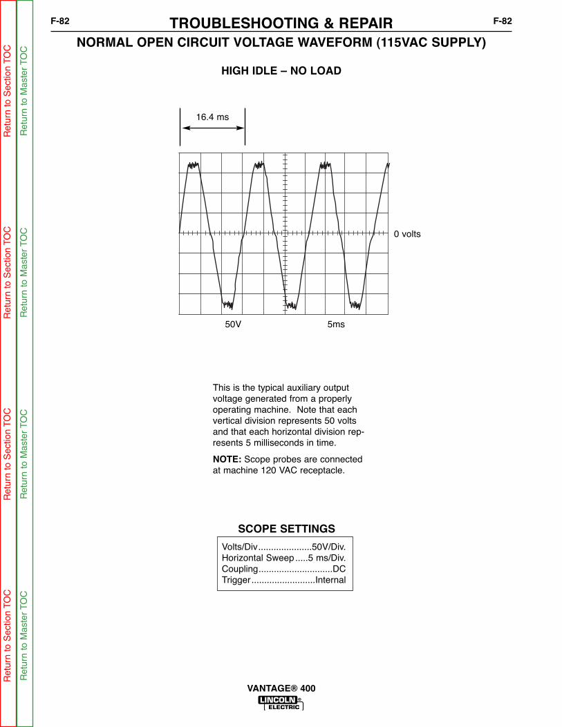
NORMAL OPEN CIRCUIT VOLTAGE WAVEFORM (115VAC SUPPLY)
HIGH IDLE – NO LOAD
TROUBLESHOOTING & REPAIRF-82 F-82
VANTAGE® 400
This is the typical auxiliary outputvoltage generated from a properlyoperating machine. Note that eachvertical division represents 50 voltsand that each horizontal division rep-resents 5 milliseconds in time.
NOTE: Scope probes are connectedat machine 120 VAC receptacle.
SCOPE SETTINGS
Volts/Div.....................50V/Div.Horizontal Sweep .....5 ms/Div.Coupling.............................DCTrigger.........................Internal
0 volts
50V 5ms
16.4 ms
Ret
urn
to S
ectio
n TO
CR
etur
n to
Sec
tion
TOC
Ret
urn
to S
ectio
n TO
CR
etur
n to
Sec
tion
TOC
Ret
urn
to M
aste
r TO
CR
etur
n to
Mas
ter
TOC
Ret
urn
to M
aste
r TO
CR
etur
n to
Mas
ter
TOC

NORMAL OPEN CIRCUIT VOLTAGE WAVEFORM (115VAC SUPPLY)
MAX CONTROL POT - HIGH IDLE - NO LOAD
TROUBLESHOOTING & REPAIRF-83 F-83
VANTAGE® 400
This is the typical DC open circuit out-put voltage generated from a properlyoperating machine. Note that eachvertical division represents 50 voltsand that each horizontal division rep-resents 5 milliseconds in time.
NOTE: Scope probes are connectedat weld output terminals.
SCOPE SETTINGS
Volts/Div.....................50V/Div.Horizontal Sweep .....5 ms/Div.Coupling.............................DCTrigger.........................Internal
0 volts
50V 5ms
CH1
Ret
urn
to S
ectio
n TO
CR
etur
n to
Sec
tion
TOC
Ret
urn
to S
ectio
n TO
CR
etur
n to
Sec
tion
TOC
Ret
urn
to M
aste
r TO
CR
etur
n to
Mas
ter
TOC
Ret
urn
to M
aste
r TO
CR
etur
n to
Mas
ter
TOC

NORMAL OPEN CIRCUIT VOLTAGE WAVEFORM (115VAC SUPPLY)
MACHINE LOADED TO 300 AMPS AT 27 VOLTS
TROUBLESHOOTING & REPAIRF-84 F-84
VANTAGE® 400
This is the typical DC output voltagegenerated from a properly operatingmachine. Note that each vertical divi-sion represents 20 volts and thateach horizontal division represents 1millisecond in time.
The machine was loaded with a resis-tance grid bank to 300 amps at 27volts.
NOTE: Scope probes are connectedat weld output terminals.
SCOPE SETTINGS
Volts/Div .....................20V/DivHorizontal Sweep .....1 ms/Div.Coupling.............................DCTrigger.........................Internal
0 volts
20V 1ms
Trig +15V CH1
Ret
urn
to S
ectio
n TO
CR
etur
n to
Sec
tion
TOC
Ret
urn
to S
ectio
n TO
CR
etur
n to
Sec
tion
TOC
Ret
urn
to M
aste
r TO
CR
etur
n to
Mas
ter
TOC
Ret
urn
to M
aste
r TO
CR
etur
n to
Mas
ter
TOC

NORMAL OPEN CIRCUIT VOLTAGE WAVEFORM (WIRE CV TAP)
MAX CONTROL POT - HIGH IDLE - NO LOAD
TROUBLESHOOTING & REPAIRF-85 F-85
VANTAGE® 400
This is the typical DC open circuit out-put voltage generated from a properlyoperating machine. Note that eachvertical division represents 50 voltsand that each horizontal division rep-resents 5 milliseconds in time.
NOTE: Scope probes are connectedat weld output terminals.
SCOPE SETTINGS
Volts/Div.....................50V/Div.Horizontal Sweep .....5 ms/Div.Coupling.............................DCTrigger.........................Internal
0 volts
50V 5ms
Ret
urn
to S
ectio
n TO
CR
etur
n to
Sec
tion
TOC
Ret
urn
to S
ectio
n TO
CR
etur
n to
Sec
tion
TOC
Ret
urn
to M
aste
r TO
CR
etur
n to
Mas
ter
TOC
Ret
urn
to M
aste
r TO
CR
etur
n to
Mas
ter
TOC

NORMAL CIRCUIT VOLTAGE WAVEFORM (WIRE CV)
MACHINE LOADED TO 300 AMPS AT 28 VOLTS
TROUBLESHOOTING & REPAIRF-86 F-86
VANTAGE® 400
This is the typical DC voltage gener-ated from a properly operatingmachine. Note that each vertical divi-sion represents 20 volts and thateach horizontal division represents 1millisecond in time.
The machine was loaded with a resis-tance grid bank to 300 amps at 28volts.
NOTE: Scope probes are connectedat weld output terminals.
SCOPE SETTINGS
Volts/Div.....................20V/Div.Horizontal Sweep .....1 ms/Div.Coupling.............................DCTrigger.........................Internal
0 volts
20V 1ms
Ret
urn
to S
ectio
n TO
CR
etur
n to
Sec
tion
TOC
Ret
urn
to S
ectio
n TO
CR
etur
n to
Sec
tion
TOC
Ret
urn
to M
aste
r TO
CR
etur
n to
Mas
ter
TOC
Ret
urn
to M
aste
r TO
CR
etur
n to
Mas
ter
TOC

Service and repair should be performed by only Lincoln Electric factory trained personnel.Unauthorized repairs performed on this equipment may result in danger to the technicianor machine operator and will invalidate your factory warranty. For your safety and to avoidelectrical shock, please observe all safety notes and precautions detailed throughout thismanual.
If for any reason you do not understand the test procedures or are unable to perform thetest/repairs safely, contact the Lincoln Electric Service Department for electrical trou-bleshooting assistance before you proceed. Call 1-888-935-3877.
DESCRIPTION
The following procedure will aid the technician in removing and replacing the output rec-tifier bridge and the choke in the Vantage® 400.
MATERIALS NEEDED
Miscellaneous hand toolsElectrical joint compound (Dow Corning)
OUTPUT RECTIFIER BRIDGE AND CHOKE REMOVAL AND REPLACEMENT
WARNING
TROUBLESHOOTING & REPAIRF-87 F-87
VANTAGE® 400
Ret
urn
to S
ectio
n TO
CR
etur
n to
Sec
tion
TOC
Ret
urn
to S
ectio
n TO
CR
etur
n to
Sec
tion
TOC
Ret
urn
to M
aste
r TO
CR
etur
n to
Mas
ter
TOC
Ret
urn
to M
aste
r TO
CR
etur
n to
Mas
ter
TOC

OUTPUT RECTIFIER BRIDGE AND CHOKE REMOVAL AND REPLACEMENT (CONTINUED)
REMOVAL PROCEDURE
1. Turn the engine off.
2. Remove negative battery cable.
3. Perform the Case Cover Removal proce-
dure.
4. Perform the Chopper Module Capacitor
Discharge procedure.
5. Remove the four screws holding the casefront to the base of the machine.
6. Remove all plugs and leads from the weldcontrol and pull coil PC boards. Be sure tomark the leads and plugs so they can beproperly re-connected. See wiring dia-gram.
7. Remove the screws holding the D4 diodebridge and the CR1 engine protection relayto the center baffle assembly, and allowthese components to remain attached tothe case front wiring.
8. Remove any additional wring and cable tiesas needed. Carefully mark leads for accu-rate re-connection.
9. Swing the case front to the side to permitaccess to the Output Rectifier and Choke.
Removing the Output Rectifier
10. Remove the heavy leads from the outputrectifier. Carefully mark the leads foraccurate re-connection, and also note theorder and position of multiple lead con-nections.
11. Remove the nuts and lock washers hold-ing the Output Rectifier to the mountingbracket. You will need to reach throughthe large access holes on either side of therectifier to reach these nuts.
12. Remove the Output Rectifier from themachine.
Removing the Output Choke
1. Remove the heavy leads from the choke.Carefully mark the leads for accurate re-connection, and also note the order andposition of the leads in multiple lead con-nections.
2. Remove the three long bolts, lock washersand nuts holding the choke the mountingbracket in the machine base. Note thatthere is no bolt in the lower right corner ofthe choke.
3. Carefully remove the choke.
REPLACEMENT PROCEDURE
Replacing the Output Choke
1. Place the choke into the machine so thatthe three mounting holes in the choke lineup with the holes in the mounting bracket.
2. Insert the three long bolts through thechoke and the mounting bracket. Place alock washer and nut on the end of each boltand tighten.
3. Reconnect the choke leads. Position theleads, bolts, washers, and nuts exactly asthey had been originally connected.Tighten the connection securely.
TROUBLESHOOTING & REPAIRF-88 F-88
VANTAGE® 400
Ret
urn
to S
ectio
n TO
CR
etur
n to
Sec
tion
TOC
Ret
urn
to S
ectio
n TO
CR
etur
n to
Sec
tion
TOC
Ret
urn
to M
aste
r TO
CR
etur
n to
Mas
ter
TOC
Ret
urn
to M
aste
r TO
CR
etur
n to
Mas
ter
TOC

OUTPUT RECTIFIER BRIDGE AND CHOKE REMOVAL AND REPLACEMENT(CONTINUED)
Replacing the Output Rectifier1. Place the Output Rectifier into the machine
so that its mounting studs fit into the holesin the bracket. Place a lock washer and anut on each stud and tighten.
2. Apply a thin film of electrical joint com-pound, (Dow Corning) between the sur-faces of the “W” leads and the OutputRectifier. Reconnect the Output Rectifier,positioning the leads, bolts, washers, andnuts exactly as hey had been originallyconnected. Tighten all of the connectionssecurely. See Wiring Diagram.
3. Swing the case front back into position.
4. Attach the case front to the machine basewith four screws.
5. Reconnect all of the leads and plugs thatwere disconnected during the removal pro-cedure, and replace any cable ties thatwere removed.
6. Perform the Case Cover Removal
Procedure.
TROUBLESHOOTING & REPAIRF-89 F-89
VANTAGE® 400
Ret
urn
to S
ectio
n TO
CR
etur
n to
Sec
tion
TOC
Ret
urn
to S
ectio
n TO
CR
etur
n to
Sec
tion
TOC
Ret
urn
to M
aste
r TO
CR
etur
n to
Mas
ter
TOC
Ret
urn
to M
aste
r TO
CR
etur
n to
Mas
ter
TOC

NOTESF-90 F-90
VANTAGE® 400
Ret
urn
to S
ectio
n TO
CR
etur
n to
Sec
tion
TOC
Ret
urn
to S
ectio
n TO
CR
etur
n to
Sec
tion
TOC
Ret
urn
to M
aste
r TO
CR
etur
n to
Mas
ter
TOC
Ret
urn
to M
aste
r TO
CR
etur
n to
Mas
ter
TOC
Service and repair should be performed by only Lincoln Electric factory trained personnel.Unauthorized repairs performed on this equipment may result in danger to the technicianor machine operator and will invalidate your factory warranty. For your safety and to avoidelectrical shock, please observe all safety notes and precautions detailed throughout thismanual.
If for any reason you do not understand the test procedures or are unable to perform thetest/repairs safely, contact the Lincoln Electric Service Department for electrical trou-bleshooting assistance before you proceed. Call 1-888-935-3877.
DESCRIPTION
This procedure will aid the technician in the removal and replacement of the ChopperModule Assembly.
Note: The Chopper Module assembly is removed and replaced as a unit. It contains noserviceable parts.
MATERIALS NEEDED
Miscellaneous hand toolsElectrical thermal joint compound - Dow Corning
CHOPPER MODULE REMOVAL AND REPLACEMENT
WARNING
TROUBLESHOOTING & REPAIRF-91 F-91
VANTAGE® 400
Ret
urn
to S
ectio
n TO
CR
etur
n to
Sec
tion
TOC
Ret
urn
to S
ectio
n TO
CR
etur
n to
Sec
tion
TOC
Ret
urn
to M
aste
r TO
CR
etur
n to
Mas
ter
TOC
Ret
urn
to M
aste
r TO
CR
etur
n to
Mas
ter
TOC

FIGURE F.18 - MODULE LEAD LOCATIONS
CHOPPER MODULE REMOVAL AND REPLACEMENT (CONTINUED)
PROCEDURE
REMOVAL
1. Turn the engine off.
2. Perform the Case Cover Removal
Procedure.
3. Perform the Chopper Module Capacitor
Discharge procedure.
4. Disconnect leads 23 and 25 at their in-linecouplings.
5. Using the 7/16” socket wrench, remove the fol-lowing leads. Label the leads before removal.Cut cable ties as needed. Note placement ofleads and fasteners: screw, lock washer, flatwasher, small lead, heavy lead.
6. Using a 3/8” socket wrench, remove the threescrews holding the power module assembly toits brackets on the vertical baffle. Remove theplastic strip with the top two screws. Be sureto support the Power Module as you removethe last screw.
7. Remove the Power Module assembly from themachine.
TROUBLESHOOTING & REPAIRF-92 F-92
VANTAGE® 400
B1
B2
B3 B6
B5
B4
2325
SL302
SL301
HL W9
HL W4
HL W6
SL14SL13
B8
HL W8
HL W5
HL W11
LED1LED1LED4LED4
LED2LED2LED3LED3
L12683-1
LED1 (B1,B2,B3)Chopper Working
LED3 (B4,B5,B6)Chopper Working
LED4PWM Signal
LED2Voltage from Rectifier
TERMINAL LEADS
B4 Heavy lead W11, Small lead 14
B5 Heavy lead W5, Small lead 13
B6 Heavy lead W8
B1 Heavy lead W6
B2 Heavy lead W4, Small lead 301
B3 Heavy lead W9, Small lead 302
Ret
urn
to S
ectio
n TO
CR
etur
n to
Sec
tion
TOC
Ret
urn
to S
ectio
n TO
CR
etur
n to
Sec
tion
TOC
Ret
urn
to M
aste
r TO
CR
etur
n to
Mas
ter
TOC
Ret
urn
to M
aste
r TO
CR
etur
n to
Mas
ter
TOC

CHOPPER MODULE REMOVAL AND REPLACEMENT (CONTINUED)
REPLACEMENT
1. Mount the heat sink to the brackets on the ver-tical baffle with the three 3/8” screws. Mountthe plastic strip with the top two screws.
2. Connect leads 23 and 25 at their in-line cou-plers.
3. Using a 7/16” wrench, attach the heavy leadsand small leads as follows. Note placement ofleads and fasteners: screw, lock washer, flatwasher, small lead, heavy lead. Apply a thincoating of electrical thermal joint compound(Dow Corning) to the mating surfaces (but notthe threads). Tighten the fasteners to between50-60 in-lbs.
4. Replace any cable ties cut at disassembly.
5. When procedures are complete, perform theCase Cover Replacement procedure.
TROUBLESHOOTING & REPAIRF-93 F-93
VANTAGE® 400
Ret
urn
to S
ectio
n TO
CR
etur
n to
Sec
tion
TOC
Ret
urn
to S
ectio
n TO
CR
etur
n to
Sec
tion
TOC
Ret
urn
to M
aste
r TO
CR
etur
n to
Mas
ter
TOC
Ret
urn
to M
aste
r TO
CR
etur
n to
Mas
ter
TOC

NOTESF-94 F-94
VANTAGE® 400
Ret
urn
to S
ectio
n TO
CR
etur
n to
Sec
tion
TOC
Ret
urn
to S
ectio
n TO
CR
etur
n to
Sec
tion
TOC
Ret
urn
to M
aste
r TO
CR
etur
n to
Mas
ter
TOC
Ret
urn
to M
aste
r TO
CR
etur
n to
Mas
ter
TOC

Service and repair should be performed by only Lincoln Electric factory trained personnel.Unauthorized repairs performed on this equipment may result in danger to the technicianor machine operator and will invalidate your factory warranty. For your safety and to avoidelectrical shock, please observe all safety notes and precautions detailed throughout thismanual.
If for any reason you do not understand the test procedures or are unable to perform thetest/repairs safely, contact the Lincoln Electric Service Department for electrical trou-bleshooting assistance before you proceed. Call 1-888-935-3877.
TEST DESCRIPTION
This procedure will aid the technician in the removal and replacement of the Rotor andStator.
MATERIALS NEEDED
Misc Hand Tools
STATOR/ROTOR REMOVAL AND REPLACEMENT PROCEDURE
WARNING
TROUBLESHOOTING & REPAIRF-95 F-95
VANTAGE® 400
Ret
urn
to S
ectio
n TO
CR
etur
n to
Sec
tion
TOC
Ret
urn
to S
ectio
n TO
CR
etur
n to
Sec
tion
TOC
Ret
urn
to M
aste
r TO
CR
etur
n to
Mas
ter
TOC
Ret
urn
to M
aste
r TO
CR
etur
n to
Mas
ter
TOC
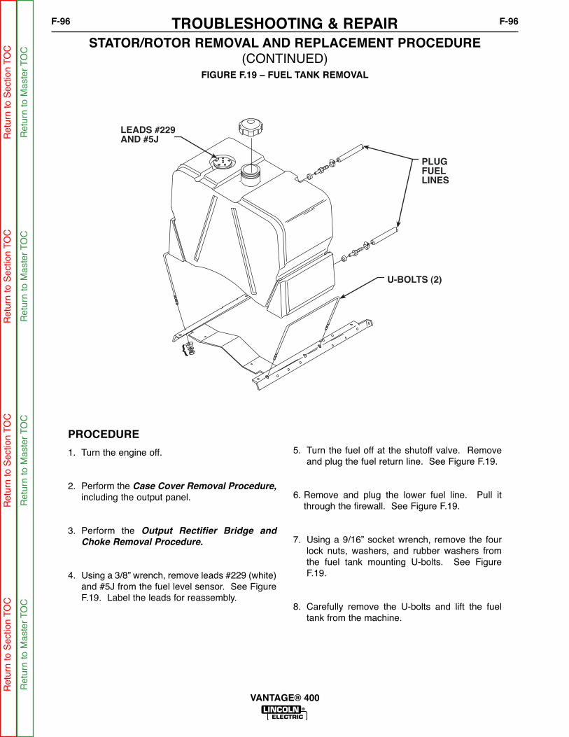
PLUGFUELLINES
U-BOLTS (2)
LEADS #229
AND #5J
{
FIGURE F.19 – FUEL TANK REMOVAL
STATOR/ROTOR REMOVAL AND REPLACEMENT PROCEDURE (CONTINUED)
PROCEDURE
1. Turn the engine off.
2. Perform the Case Cover Removal Procedure,
including the output panel.
3. Perform the Output Rectifier Bridge and
Choke Removal Procedure.
4. Using a 3/8” wrench, remove leads #229 (white)and #5J from the fuel level sensor. See FigureF.19. Label the leads for reassembly.
5. Turn the fuel off at the shutoff valve. Removeand plug the fuel return line. See Figure F.19.
6. Remove and plug the lower fuel line. Pull itthrough the firewall. See Figure F.19.
7. Using a 9/16” socket wrench, remove the fourlock nuts, washers, and rubber washers fromthe fuel tank mounting U-bolts. See FigureF.19.
8. Carefully remove the U-bolts and lift the fueltank from the machine.
TROUBLESHOOTING & REPAIRF-96 F-96
VANTAGE® 400
Ret
urn
to S
ectio
n TO
CR
etur
n to
Sec
tion
TOC
Ret
urn
to S
ectio
n TO
CR
etur
n to
Sec
tion
TOC
Ret
urn
to M
aste
r TO
CR
etur
n to
Mas
ter
TOC
Ret
urn
to M
aste
r TO
CR
etur
n to
Mas
ter
TOC

#201A-
5H
#200
200A
#6A
FILTER
CAPACITOR
FIELD DIODE
RECTIFIER BRIDGE
FIGURE F.20 – DOOR REMOVAL
STATOR/ROTOR REMOVAL AND REPLACEMENT PROCEDURE (CONTINUED)
PROCEDURE
9. Disconnect plug J30 at the right front side. SeeFigure F.20.
10. Using the slot head screw driver, disconnectleads #200B, #200A(+) and #201A(-) from thefilter capacitor. Label the leads.
11. Label and remove leads 5H, 200, 200A, 6A,201A, 5H from the field bridge rectifier. SeeFigure F.20.
TROUBLESHOOTING & REPAIRF-97 F-97
VANTAGE® 400
Ret
urn
to S
ectio
n TO
CR
etur
n to
Sec
tion
TOC
Ret
urn
to S
ectio
n TO
CR
etur
n to
Sec
tion
TOC
Ret
urn
to M
aste
r TO
CR
etur
n to
Mas
ter
TOC
Ret
urn
to M
aste
r TO
CR
etur
n to
Mas
ter
TOC
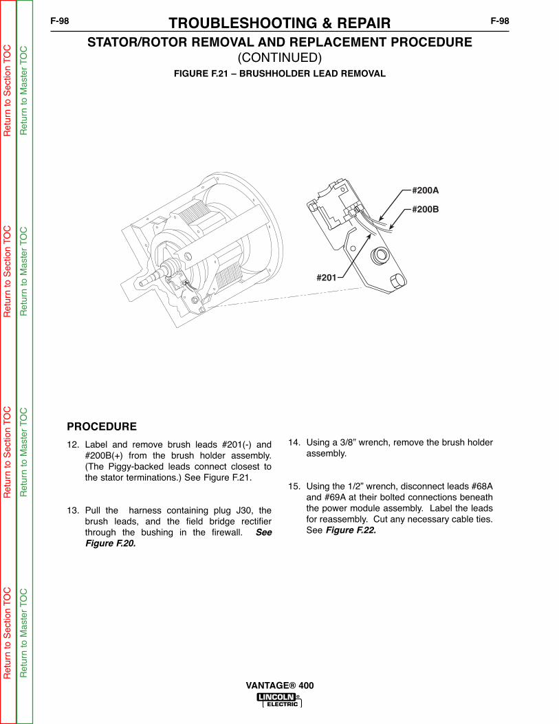
#200A
#200B
#201
FIGURE F.21 – BRUSHHOLDER LEAD REMOVAL
STATOR/ROTOR REMOVAL AND REPLACEMENT PROCEDURE (CONTINUED)
PROCEDURE
12. Label and remove brush leads #201(-) and#200B(+) from the brush holder assembly.(The Piggy-backed leads connect closest tothe stator terminations.) See Figure F.21.
13. Pull the harness containing plug J30, thebrush leads, and the field bridge rectifierthrough the bushing in the firewall. See
Figure F.20.
14. Using a 3/8” wrench, remove the brush holderassembly.
15. Using the 1/2” wrench, disconnect leads #68Aand #69A at their bolted connections beneaththe power module assembly. Label the leadsfor reassembly. Cut any necessary cable ties.See Figure F.22.
TROUBLESHOOTING & REPAIRF-98 F-98
VANTAGE® 400
Ret
urn
to S
ectio
n TO
CR
etur
n to
Sec
tion
TOC
Ret
urn
to S
ectio
n TO
CR
etur
n to
Sec
tion
TOC
Ret
urn
to M
aste
r TO
CR
etur
n to
Mas
ter
TOC
Ret
urn
to M
aste
r TO
CR
etur
n to
Mas
ter
TOC
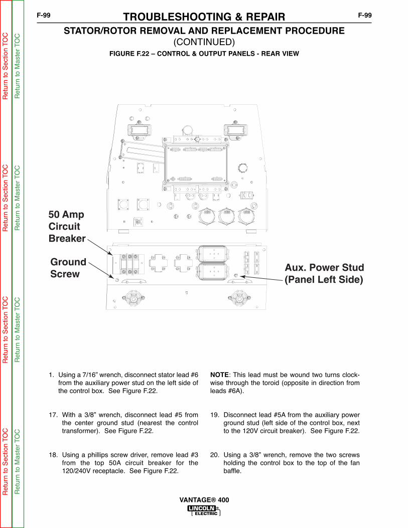
50 Amp CircuitBreaker
GroundScrew
Aux. Power Stud(Panel Left Side)
FIGURE F.22 – CONTROL & OUTPUT PANELS - REAR VIEW
STATOR/ROTOR REMOVAL AND REPLACEMENT PROCEDURE (CONTINUED)
1. Using a 7/16” wrench, disconnect stator lead #6from the auxiliary power stud on the left side ofthe control box. See Figure F.22.
17. With a 3/8” wrench, disconnect lead #5 fromthe center ground stud (nearest the controltransformer). See Figure F.22.
18. Using a phillips screw driver, remove lead #3from the top 50A circuit breaker for the120/240V receptacle. See Figure F.22.
NOTE: This lead must be wound two turns clock-wise through the toroid (opposite in direction fromleads #6A).
19. Disconnect lead #5A from the auxiliary powerground stud (left side of the control box, nextto the 120V circuit breaker). See Figure F.22.
20. Using a 3/8” wrench, remove the two screwsholding the control box to the top of the fanbaffle.
TROUBLESHOOTING & REPAIRF-99 F-99
VANTAGE® 400
Ret
urn
to S
ectio
n TO
CR
etur
n to
Sec
tion
TOC
Ret
urn
to S
ectio
n TO
CR
etur
n to
Sec
tion
TOC
Ret
urn
to M
aste
r TO
CR
etur
n to
Mas
ter
TOC
Ret
urn
to M
aste
r TO
CR
etur
n to
Mas
ter
TOC
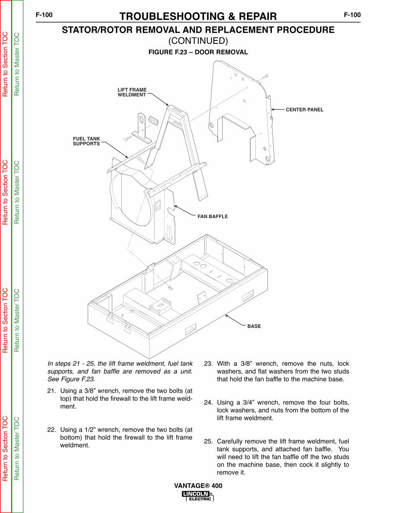
CENTER PANEL
LIFT FRAME
WELDMENT
BASE
FUEL TANK
SUPPORTS
FAN BAFFLE
FIGURE F.23 – DOOR REMOVAL
STATOR/ROTOR REMOVAL AND REPLACEMENT PROCEDURE (CONTINUED)
In steps 21 - 25, the lift frame weldment, fuel tank
supports, and fan baffle are removed as a unit.
See Figure F.23.
21. Using a 3/8” wrench, remove the two bolts (attop) that hold the firewall to the lift frame weld-ment.
22. Using a 1/2” wrench, remove the two bolts (atbottom) that hold the firewall to the lift frameweldment.
23. With a 3/8” wrench, remove the nuts, lockwashers, and flat washers from the two studsthat hold the fan baffle to the machine base.
24. Using a 3/4” wrench, remove the four bolts,lock washers, and nuts from the bottom of thelift frame weldment.
25. Carefully remove the lift frame weldment, fueltank supports, and attached fan baffle. Youwill need to lift the fan baffle off the two studson the machine base, then cock it slightly toremove it.
TROUBLESHOOTING & REPAIRF-100 F-100
VANTAGE® 400
Ret
urn
to S
ectio
n TO
CR
etur
n to
Sec
tion
TOC
Ret
urn
to S
ectio
n TO
CR
etur
n to
Sec
tion
TOC
Ret
urn
to M
aste
r TO
CR
etur
n to
Mas
ter
TOC
Ret
urn
to M
aste
r TO
CR
etur
n to
Mas
ter
TOC
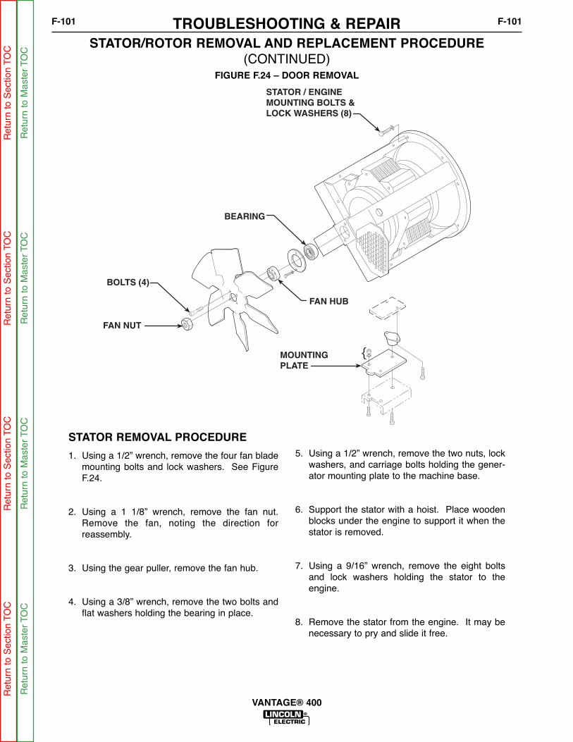
{
STATOR / ENGINEMOUNTING BOLTS &LOCK WASHERS (8)
BEARING
BOLTS (4)
FAN NUT
FAN HUB
MOUNTINGPLATE
FIGURE F.24 – DOOR REMOVAL
STATOR/ROTOR REMOVAL AND REPLACEMENT PROCEDURE (CONTINUED)
STATOR REMOVAL PROCEDURE
1. Using a 1/2” wrench, remove the four fan blademounting bolts and lock washers. See FigureF.24.
2. Using a 1 1/8” wrench, remove the fan nut.Remove the fan, noting the direction forreassembly.
3. Using the gear puller, remove the fan hub.
4. Using a 3/8” wrench, remove the two bolts andflat washers holding the bearing in place.
5. Using a 1/2” wrench, remove the two nuts, lockwashers, and carriage bolts holding the gener-ator mounting plate to the machine base.
6. Support the stator with a hoist. Place woodenblocks under the engine to support it when thestator is removed.
7. Using a 9/16” wrench, remove the eight boltsand lock washers holding the stator to theengine.
8. Remove the stator from the engine. It may benecessary to pry and slide it free.
TROUBLESHOOTING & REPAIRF-101 F-101
VANTAGE® 400
Ret
urn
to S
ectio
n TO
CR
etur
n to
Sec
tion
TOC
Ret
urn
to S
ectio
n TO
CR
etur
n to
Sec
tion
TOC
Ret
urn
to M
aste
r TO
CR
etur
n to
Mas
ter
TOC
Ret
urn
to M
aste
r TO
CR
etur
n to
Mas
ter
TOC
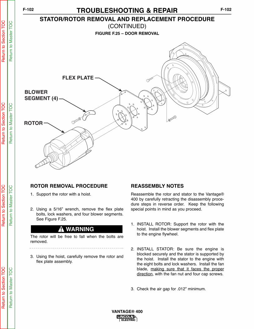
FLEX PLATE
BLOWERSEGMENT (4)
ROTOR
FIGURE F.25 – DOOR REMOVAL
STATOR/ROTOR REMOVAL AND REPLACEMENT PROCEDURE (CONTINUED)
TROUBLESHOOTING & REPAIRF-102 F-102
VANTAGE® 400
ROTOR REMOVAL PROCEDURE
1. Support the rotor with a hoist.
2. Using a 5/16” wrench, remove the flex platebolts, lock washers, and four blower segments.See Figure F.25.
The rotor will be free to fall when the bolts areremoved.
3. Using the hoist, carefully remove the rotor andflex plate assembly.
REASSEMBLY NOTES
Reassemble the rotor and stator to the Vantage®400 by carefully retracting the disassembly proce-dure steps in reverse order. Keep the followingspecial points in mind as you proceed.
1. INSTALL ROTOR: Support the rotor with thehoist. Install the blower segments and flex plateto the engine flywheel.
2. INSTALL STATOR: Be sure the engine isblocked securely and the stator is supported bythe hoist. Install the stator to the engine withthe eight bolts and lock washers. Install the fanblade, making sure that it faces the properdirection, with the fan nut and four cap screws.
3. Check the air gap for .012” minimum.
WARNING
Ret
urn
to S
ectio
n TO
CR
etur
n to
Sec
tion
TOC
Ret
urn
to S
ectio
n TO
CR
etur
n to
Sec
tion
TOC
Ret
urn
to M
aste
r TO
CR
etur
n to
Mas
ter
TOC
Ret
urn
to M
aste
r TO
CR
etur
n to
Mas
ter
TOC

FLEX PLATE
BLOWERSEGMENT (4)
ROTOR
FIGURE F.29 – ROTOR REMOVAL & REPLACEMENT
STATOR/ROTOR REMOVAL AND REPLACEMENT PROCEDURE (CONTINUED)
PROCEDURE
1. Remove the screws and disc clamping barsfrom the rotor coupling disc, and remove therotor.
NOTE: earlier machines used three 0.31” thickclamping bars and later models use six 0.14” thickclamping bars arranged in three sets of two barseach.
If the rotor is to be replaced, remove the screws,rotor clamping ring and coupling disc from the rotorhub.
Replacing the Rotor
1. Whenever the rotor and stator are separated, itis highly recommended that a new bearing andtolerance ring be installed when the rotor andstator are reassembled.
2. Examine the rotor, coupling disc, clamping ring,clamping bars, screws, lock washers, and theengine flywheel. Make sure that all of the partsare clean and in good condition.
3. Install a new bearing on the rotor shaft.
4. Assemble the coupling disc and clamping ringto the rotor hub. The surface of the disc withthe stamping burrs should be against the rotorhub. The side of the clamping ring with theradius should be placed against the couplingdisc. See Figure F.29.
5. Insert the screws with lock washers and evenlytighten to a torque of 17 to 19 Ft-Lbs.
6. Lift the rotor assembly with the hoist and liftingstraps and recheck the engine flywheel andcoupling disk for anything that might preventproper seating.
7. To attach the coupling disk to the engine fly-wheel, align the screw holes and insert the sixscrews, with lock washers, through the discclamping bars and the coupling disc and intothe engine flywheel.
8. Evenly tighten all the screws to a torque of 17 to19 Ft-Lbs.
TROUBLESHOOTING & REPAIRF-103 F-103
VANTAGE® 400
Ret
urn
to S
ectio
n TO
CR
etur
n to
Sec
tion
TOC
Ret
urn
to S
ectio
n TO
CR
etur
n to
Sec
tion
TOC
Ret
urn
to M
aste
r TO
CR
etur
n to
Mas
ter
TOC
Ret
urn
to M
aste
r TO
CR
etur
n to
Mas
ter
TOC
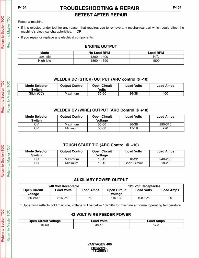
TROUBLESHOOTING & REPAIRF-104 F-104
VANTAGE® 400
RETEST AFTER REPAIRRetest a machine:
• If it is rejected under test for any reason that requires you to remove any mechanical part which could affect themachine’s electrical characteristics. OR
• If you repair or replace any electrical components.
ENGINE OUTPUT
Mode No Load RPM Load RPMLow Idle 1300 - 1400 N/AHigh Idle 1860 - 1890 1800
WELDER DC (STICK) OUTPUT (ARC control @ -10)
Mode Selector Output Control Open Circuit Load Volts Load AmpsSwitch Volts
Stick (CC) Maximum 55-60 36-38 400
WELDER CV (WIRE) OUTPUT (ARC Control @ +10)
Mode Selector Output Control Open Circuit Load Volts Load AmpsSwitch Voltage
CV Maximum 55-60 36-38 290-310CV Minimum 55-60 17-19 220
TOUCH START TIG (ARC Control @ +10)
Mode Selector Output Control Open Circuit Load Volts Load AmpsSwitch Voltage
TIG Maximum 10-15 18-22 240-260TIG Minimum 10-15 Short Circuit 18-28
AUXILIARY POWER OUTPUT
240 Volt Receptacle 120 Volt ReceptaclesOpen Circuit Load Volts Load Amps Open Circuit Load Volts Load Amps
Voltage Voltage230-264* 216-252 50 115-132 108-126 20
* Upper limit reflects cold machine, voltage will be below 132/264 for machine at normal operating temperature.
42 VOLT WIRE FEEDER POWER
Open Circuit Voltage Load Volts Load Amps40-50 38-48 8=.5
Ret
urn
to S
ectio
n TO
CR
etur
n to
Sec
tion
TOC
Ret
urn
to S
ectio
n TO
CR
etur
n to
Sec
tion
TOC
Ret
urn
to M
aste
r TO
CR
etur
n to
Mas
ter
TOC
Ret
urn
to M
aste
r TO
CR
etur
n to
Mas
ter
TOC

TABLE OF CONTENTS - DIAGRAM SECTIONG-1 G-1
VANTAGE® 400
Electrical Diagrams . . . . . . . . . . . . . . . . . . . . . . . . . . . . . . . . . . . . . . . . . . . . . . . . . . . . . . . . . . . . . . . . . . . . .G-1
Wiring Diagram - Complete Machine (G5481) . . . . . . . . . . . . . . . . . . . . . . . . . . . . . . . . . . . . . . . . . . . . . .G-2
Schematic – Complete Machine (G5597 Page 1) . . . . . . . . . . . . . . . . . . . . . . . . . . . . . . . . . . . . . . . . . . . .G-3
Schematic – Complete Machine (G5597 Page 2) . . . . . . . . . . . . . . . . . . . . . . . . . . . . . . . . . . . . . . . . . . . .G-4
Schematic – Weld Control PC Board – (G5506 Page 1)* . . . . . . . . . . . . . . . . . . . . . . . . . . . . . . . . . . . . . .G-5
Schematic – Weld Control PC Board – (G5506 Page 2)* . . . . . . . . . . . . . . . . . . . . . . . . . . . . . . . . . . . . . .G-6
Schematic – Weld Control PC Board – (G5506 Page 3)* . . . . . . . . . . . . . . . . . . . . . . . . . . . . . . . . . . . . . .G-7
Schematic – Weld Control PC Board – (G5506 Page 4)* . . . . . . . . . . . . . . . . . . . . . . . . . . . . . . . . . . . . . .G-8
Schematic – Weld Control PC Board – (G5506 Page 5)* . . . . . . . . . . . . . . . . . . . . . . . . . . . . . . . . . . . . . .G-9
Schematic – Idler PC Board (G4828-2)* . . . . . . . . . . . . . . . . . . . . . . . . . . . . . . . . . . . . . . . . . . . . . . . . . .G-10
Schematic – Chopper PC Board (L12717-1C0)* . . . . . . . . . . . . . . . . . . . . . . . . . . . . . . . . . . . . . . . . . . . .G-11
Schematic – OCV Indicator PC Board (G4406-2D0)* . . . . . . . . . . . . . . . . . . . . . . . . . . . . . . . . . . . . . . . .G-12
Schematic – By Pass / Stabilizer PC Board (S22530-3D0) . . . . . . . . . . . . . . . . . . . . . . . . . . . . . . . . . . .G-13
PC Board Assembly – By Pass / Stabilizer PC Board (L10121-3) . . . . . . . . . . . . . . . . . . . . . . . . . . . . . .G-14
* NOTE: Many PC Board Assemblies are now totally encapsulated, surface mounted and or multi-layeredand are therefore considered to be unserviceable. Assembly drawings of these boards are nolonger provided.
Ret
urn
to M
aste
r TO
CR
etur
n to
Mas
ter
TOC
Ret
urn
to M
aste
r TO
CR
etur
n to
Mas
ter
TOC

ELECTRICAL DIAGRAMS G-2
VANTAGE® 400®®
WIRING DIAGRAM - COMPLETE MACHINE - (G5481)
") TO A
CB6
10A
42B
42
RECTIFIER BRIDGE
42A
41A
41
START BUTTON
222
MODE SELECTOR SWITCH
206A
214
S5
218
1
2
3
220
A
4
206S
208A
+
50MV=400AMPS
W4 & W5 W2 & W3 W1 & W6
204S
STATOR 42V WINDING
G5481B
208
31
32
4B
21
77B
21
2B
75B
GND-A
41A
42A
76B
115VAC
CONTACTOR
WORK
42VAC
GROUND
14 PIN REMOTE
206C
J
A
D
C
H
B
K
E
F
G
I
I
2B
4B
GND-B
A
B
C
D
E
F
76B
75B
6 PIN REMOTE
2A
4A
75A
76A
77A77B
-
+
23 25
41A
NEUTRAL STUD ONAUXILIARY POWERRECEPTACLE PANEL
AUXILIARY POWER LEADS PASS THROUGHTOROID THREE TIMES IN DIRECTION INDICATED
B2-POS
B4-NEG
B4-NEG
B5-POS
B1-NEG
B2-POS
CHOPPERPCB3
13C
14
260261
B6
B5
B4
B1
B2
B3
CV
CC
TIG
PIPE
B8B7
GROUNDED BY MOUNTING
GND-J
GND-A
GND-B
31
5H
GND-J
5A
5
GND-C
GND-D
GND-E
50A3 POLE
6D
WHITE
J12
CB1
20A
6F
J11
WHITE
HOT
CB3
HOT
5D5B
STATOR AUXILIARY WINDINGS
GND-L
5
3
GND-E
5A
GND-D
6A
CB2
20A
J13
32A
3E
6
6A
B5-POS
B1-NEG
L1 CHOKE
BYPASS FILTERASSEMBLY
SWITCH CONTACTS SHOWN IN "+" POSITION
REMOTECONTROL
REMOTECONTROL
CONTACTOR
GROUND
VOLTMETER AMMETER
M1M2
M3M4
M5M6
M9M10
M1M2
M3M4
M5M6
M9M10
1 5
220
VOLT METER
M1
M2
M3
M4
M5
M6
M9
M10
1 5
AMMETER
M1
M2
M3
M4
M5
M6
M9
M10
25
23
VRD WELD BOARD
278
279
277
2
1204S
206S
208C
256
260
214
PCB1
1 8
9 16
J7 J3
1
9 16
8
16
712
1
16 9
8
6 10
J4J5
6 10
CONTROL, MODE SEL. CHOPPER, POWER, PWM, THERMAL
13
14
77
76
75
2 475A
76A
77A
J6
SHUNT
J1AMPHENOL,I.D.
J2ENGINE,PERIPHERAL
ALT
247244
5R
ENGPROT
232K232B
232C
232C
OILPRESSURE
2412285L
229
232B 5M
COOLANT TEMPERATURE
232K 5K
4 1 4 1 4 1
J53 J52 J51
12 VOLT GROUND STUD ON UPPER CONTROL PANEL
5L5M
5T 5J5K
RUN/STOPSWITCH
SHOWN IN "RUN" POSITION
238B
236A
CB510A
236B
STOP
RUN
238A
231
SENSOR
SENSOR
FUEL LEVELSENSOR
WK
235
234
5J
229
228
241
G
235
SWITCH
SWITCH
OIL PRESSURESENSOR & SWITCH
COOLANT TEMPERATURESENSOR & SWITCH
-
+
-
+201
BRUSH
ROTOR
4200MFD
BRUSH
201A
200A
201
300V
200B
5G
257
261
PULLCOIL
HOLDCOIL
5P
SHUTDOWNSOLENOID
262
226
IDLERSOLENOID
232L
BLKRED
J55
P55
FUEL
SHOWN IN"HIGH" POSITION
IDLERCONTROLSWITCHAUTO
HIGH
257
256HOUR METER
2A
4A
4
2
WELDING TERMINALCONTROL SWITCH
SHOWN IN "ALWAYS ON" POSITION
218
222
232L
4
GND-C
120/240V
J10
X
Y
ZX
W
Y
GND-L
5G
6E
3C
3D
STATORWELD
WINDINGS
W6W6
W1W1W4
W5
W4
W5
W3W3
W2W2
4
240V3PH
3B
6C
4A
LINE TERMINALS
ENGINE BLOCK
+
12V BATTERY238
-
+STARTING
MOTOR
STARTERSOLENOID
ALTERNATOR
231
238A
5S
1
226
234
6
10
J31
247
232F
232
5
1 2
4
J32
3
B1
B3
B4
B2
IDLER/ENGINE SHUTDOWN PCB2
232
WHT
227
405
5R
5S 227
1 3
6
J33
4271
200
405
6
3
COIL
D+243
GLOW PLUG BUTTON
GLOWPLUGS
239
238C
+
-262
263
232F
GROUND STUD IN UPPER CONTROL PANEL
5C
5B
31
5D
3D 6E
5C
2523
279
R2
27777 76
R1
278
ARC CONTROL
75
CCW
OUTPUT CONTROLCCW
10K10K
VIEWEDFROMBACK
VIEWEDFROMBACK
13A
15
R4
6A
5H
200
POSITIVE BRUSH CONNECTED TOSLIP RING NEAREST TO THELAMINATION
236A
+
263
-
5T
206
208D
POS-SHUNTPOS-SHUNT
WELDING OUTPUTTERMINAL
WELDING OUTPUTTERMINAL
B3 CHOKE
B6 CHOKEGND-K
GND-K
1 4
GROUND STUD ON AUXILIARYPOWER RECEPTACLE PANEL
5P
6D
4A
3C
6C
GENERATOR SUPPORT
ALL CASEFRONT COMPONENTS SHOWN VIEWED FROM REAR
ELECTRICAL SYMBOLS PER E1537
VANTAGE 400 WIRING DIAGRAM
R
CLEVELAND, OHIO, U.S.A.
243
13
14C
216
215
215216
298
VRDON
OFF
VRDGREEN
298297
VRDRED
296A
299
10
51
6
1 3
64
VRD DISPLAYPCB4
208B 206B
13C 14C
250
250
J56
P56
5U
244
5U
J61 J60
296
296296A
208B
GND-M
GND-M
42B
32A
13C 13
400
400
FERRITE
NOTE:FERRITE ONLEADS 75A & 76A(3 TURNS)
FERRITE
FERRITE ON TWISTED PAIR4 TURNS
206A
206B
WIRE FEEDERVOLTMETERSWITCH
208A 208C
G-2
NOTE: This diagram is for reference only. It may not be accurate for all machines covered by this manual. The wiring diagram specific to your code is pasted inside one of the enclosure panels of your machine.Re
turn
to S
ection T
OC
Re
turn
to S
ection T
OC
Retu
rn t
o S
ectio
n T
OC
Retu
rn t
o S
ection T
OC
Re
turn
to M
aste
r T
OC
Retu
rn t
o M
aste
r T
OC
Retu
rn t
o M
aste
r T
OC
Retu
rn t
o M
aste
r T
OC

ELECTRICAL DIAGRAMS G-3
VANTAGE® 400®®
SCHEMATIC - COMPLETE MACHINE - (G5597 PAGE 1)
EN
-170
SO
LID
ED
GE
G5597
VANTAGE 400 (PERKINS)
MACHINE SCHEMATIC
NONE
G5388Maglietta
BAM
DO NOT SCALE THIS DRAWING
DRAWN BY:
DESIGN INFORMATION
ENGINEER:
APPROVED:
EQUIPMENT TYPE:
SUBJECT:SCALE:
NA CRM22115-GA
1PAGE ___ OF ___2
ENGINEERING CONTROLLEDMANUFACTURER: No
THIS DOCUMENT CONTAINS PROPRIETARY INFORMATION OWNED BY LINCOLN GLOBAL, INC. AND MAY NOT BE DUPLICATED, COMMUNICATEDTO OTHER PARTIES OR USED FOR ANY PURPOSE WITHOUT THE EXPRESS WRITTEN PERMISSION OF LINCOLN GLOBAL, INC.PROPRIETARY & CONFIDENTIAL:
C10/26/2006tMATERIAL TOLERANCE (" ") TO AGREE
WITH PUBLISHED STANDARDS.
ON ALL ANGLES IS ± .5 OF A DEGREEON 3 PLACE DECIMALS IS ± .002ON 2 PLACE DECIMALS IS ± .02
UNLESS OTHERWISE SPECIFIED TOLERANCE:MANUFACTURING TOLERANCE PER E2056
REVISED LEAD 208C ROUTING.CHANGE DETAIL:
REFERENCE:
MATERIALDISPOSITION:
APPROVALDATE:
PROJECTNUMBER:
DOCUMENTNUMBER:
DOCUMENTREVISION:
G5597
LEAD COLOR CODE:
B-BLACK OR GRAYG-GREENO-ORANGER-RED OR PINKU-BLUEW-WHITEY-YELLOW
COMPONENT VALUE UNITS:
CAPACITOR: MFD/VOLTS
RESISTOR: OHMS/WATTS
CONNECTOR PIN NUMBERS:
VIEW OF CONNECTOR ON PC BOARD
1 2 6
7 12LATCH
EX. 12 PIN CONNECTOR
LABELS:
COMM ON
FRAME GROUND
EARTH GROUND
THREE PHASERECTIFIER
3200uf300vdc
SHUNT
50MV=400 AMPS
206S204S
CURRENT LEVELFEED BACK SIGNAL
POSITIVEOUTPUTTERMINAL
NEGATIVEOUTPUTTERMINAL
BY-PASSPC BOARD
206B
208
5AAC AUX. POWER
42 VOLT ACWIRE FEEDERPOWER
41
42
FOUR POLE 1800 RPM ALTERNATOR
120 VOLT ACPOWER FORROTOR FIELD CIRCUIT
12 VOLTBATTERY
ENGINESTARTERSOLENOID
START BUTTONSWITCH
RUN-STOP SWITCHSHOWN IN RUN POS.
FRAMEGROUND
W2W2
W3W3
W5W4W5W4
W1W1 W6
W6
3
5
6
ENGINE PROTECTION/IDLE CONTROLPC BOARD
(J31-9) 262
229
(J31-1) 232
(J31-6) 234
SENDER
SENDER
SWITCH
TEMPERATURE
OIL PRESSURE
SWITCH
ENG.PROT.
FUEL TEMP.
241228
238
200 (J33-5)
227 (B3)
IDLE SOL.PULL COIL
226 (J31-8)
5S (B1)
J31-2 (232F)
ALT.
+12 VOLTS RUN
ENGINESTARTER
+12 VOLTS RUN
+12 VOLTS RUN
201
200200A
21
WIREFEEDERVOLTMETERPOLARITYSWITCH
206A
208A
231238A
+160 VDC
6A5H
+
236B
232H
232DCB 10A
236A
C E
CHOPPPPER PC BOARD
GATE SIGNAL
IGBT (16)
B7 B8
B6
B3
B5B2
B4B1
+COM
FLYBACKDIODES (12)
FILTERCAPACITORS (6)
+
7,200uF x6
CHOKE
DC BUS VOLTAGE90+/-10VDC @ HI IDLE
ARC VOLTAGE FEEDBACK SIGNAL
R1OUTPUTCONTROL 10K
77 (J7-1)
76 (J7-4)
75 (J7-5)
R2ARCCONTROL 10K
279 (J7-6)
278 (J7-7)
277 (J7-8)
(J3-14) 257(J3-7) 256
IDLER SWITCH
(J1-4) 2
(J1-3) 4WELD TERM. SW.
MODESWITCHCC
CVPIPE
TIG
(J7-9) 214(J7-14) 218
(J7-15) 220(J7-16) 222
260 (J3-4)
261 (J3-3)
TOROID: Senses auxiliary power load to activate idler.Generator leads 3 and 6 pass through torroid 3 times inopposite directions.
VRD WELD CONTROLPC BOARD
204S (J6-1)
206S (J6-2)
208C (J3-15)
23 (J3-10)
25 (J3-9)
5G (J2-3)
REMOTECONTROL 10K
77A (J1-11)
76A (J1-14)
75A (J1-10)
10 V
0-10 V
0 V
10 V
-15 V (W/O POT.)
0 V
0 V
15 V
15 V
0 V
(TO AMPHENOL)
(TO AMPHENOL)
2A
4A
(TO AMPHENOL)
31
32
41A
ABCDEF
77A
21
42A
75A
GND-A
4A
2A
76A
77B
76B
75B
GROUND
CONNECTOR
TO CONNECTOR J1
115VAC
CONTACTOR
WORK
REMOTECONTROL
42VAC
GROUND
JA
DC
H
B
K
EFG
I
77B
76B
75B
GND-B
4B
2B
4B
2B
13 (J3-8)
14 (J3-16)
(J1-8) 400
(J1-13) 400
400 I.D. JUMPER (Part of round plug and lead assembly.)
LOW IDLE COMM AND (0V @ LOW IDLE)
TWISTEDPAIR
TWISTEDPAIR
ROTOR FLASHING
Located on back ofcontrol panel.
P/N G5507-1
Located on wiring behindreceptacles.
Control board common isat welder positive outputand shunt
Control board circuits associated with J2 are partof engine electrical system and are common toframe ground (negative battery terminal). Rotor Flashing: +12 volts
@ 0.5 ampsuntil generator builds upthen +160 volts @ 0 amps.
Swich closed for high idle.
WELD AMMETER WELD VOLTMETER
(J4-1 to 10) (J5-1 to 10)
14
14 13
TWISTEDPAIR
R450 OHM100 W
R4 is located aboverectifier on upper leftinterior panel behindupper control panel.
5J
1 1 14 4 4
IDLE SOL.HOLD COIL
247 (J31-4)
IGBT'S, FLYBACK DIODES ANDFILTER CAPACITORS ARE INTEGRALTO CHOPPER MODULES AND NOTINDIVIDUALLY REPLACEABLE.
STATORWELD
WINDINGS
ROTOR FIELDSLIP RINGS
REMOTECONTROL
OILPRESS.
FUEL LVL.SENSOR
Choke mounted behindoutput terminal panel.
Power Supplyto ControlBoard
PWM Signal to Chopper15 volt @ 20 kHz
Chopper module is located on right side ofinterior panel behind upper control panel.
Rectifier is located on left side of interiorpanel behind upper control panel.
Shunt on back of positiveoutput terminal
Located on back ofoutput panelbetween terminals
60 TO 65 VAC PHASE TO PHASEAT HIGH IDLE
REVOLVING FIELDRESISTANCE APPROX.25 OHMS @ 75F
Field capacitor located on lower rear offan baffle on right side of machine.
Battery voltage:12.6 volts at rest14 volts enginerunning
Located on rearof control panel
left side.
0.2 OHM 11 OHMS
Oil Pressure Switchcloses on lowoil pressure.
Temperature Switchcloses on hightemperature.
Engine protectioncircuit. 1 minutedelay on engine
start.
3/4 SecondTimer
YELLOWLAMP
230 OHMS EMPTY30 OHMS FULL
10 OHMS @ 0 PSI100 OHMS @ 75PS1
500-600 OHMS COLD50-100 OHMS HOT
(SEE SHEET 2 FORSIMPLIFIED
CONTROL BOARDSCHEMATIC)
(SIMPLIFIED BOARDSCHEMATIC)
(SIMPLIFIEDBOARD
SCHEMATIC)
250 (J3-5)
250 (J3-1)Jumper required for output.
Low oilpressure or
hightemperatureshutdown
4
6A 5H
Located in top of fuel tank
Located on front panel
Located in engine blockRight side, rear
Located in engine thermostat housing onLeft side of engine
Located on auxiliaryoutput panel
Located in injection pumpon right side of engine
J55-3
J55-4 J55-2
(J1-5) 400
(J1-12) 400
Weld Voltmeter and Ammeterare standard on Vantage 400
HOURMETER
+ _(J31-10) 263
VoltageRegulator
+10 Volts
405 (J32-2)
(J2-5) 405
J56
9 Ohmsat 75vF
SHUT DOWN COIL
Located on right side of engineinside engine access door
12 volt ground stud on rear of upper control panel.
Located on frontcontrol panel.
Located on frontcontrol panel.
Located on frontcontrol panel.
Located on leftside of engineblock at flywheelhousing.
Battery is located in thelower left front ofmachine behind lowercontrol panel. Ground stud on
generator crosssupport.
J55 is locatednear idle solenoid.
12 volt groundstud on rear ofupper controlpanel.
Located on frontcontrol panel.
12 volt ground studon rear of uppercontrol panel.
Auxiliary power to frontpanel receptacles via circuitbreakers on front panel.
P56
P55-4
P55-3
P55-2
244 (J33-1)
YELLOWLAMP
243 (J33-6)
238 243
D+
+
ENGINEALTERNATOR
Located on left sideof engine nearradiator fan.
208C
(J7-2) 215(J7-10) 216
CONNECTOR
Located in engineintake manifold
GLOW PLUGS
239Located on frontcontrol panel.
GLOW PLUG BUTTON SWITCH
238C238B
3, 4 AND 6 - 240 VAC 3 PHASE3 TO 6 - 240 VAC 1 PHASE6A TO 5 -120 VAC 1 PHASE3 TO 5 - 120 VAC 1 PHASE
208B206B
14C
1313C
Located under VRD Control PCBd on the back of the control panel
Weld volts >32, RED light onWeld volts <32, GREEN light on
+-
VDR DISPLAY PC BOARD
Switching PowerSupply VoltageRegulator (J60-1) 13C
(J60-6) 14C
(J61-8) 206B
(J61-1) 208B
+15DC
296A
296
GRN
RED
298 (J61-10)
297 (J61-9)
299 (J61-4)
+-
VRDSWITCH
Diode Bridge located on upper controlpanel, right rear.
Located on VRD control mountingbracket. Shown in "ON" position
VRD "OFF"
TigPipeCV
1212265858585858MinMax
CC
Open Circuit Volts:
Open Circuit Volts:
CCMax Min12 1258 58--- ---12 12
CVPipeTig
VRD "ON"
**NOTE: Pipe Mode is not active with VRD On
Ferrite on Lead 208A2 turns
Ferrite on meter leads
Ferrite onTwisted Pair4 turns
Meters display setpoint volts or amps when not welding.Meters display actual volts and amps when welding.Hold function displays actual volts and amps forapproximately 5 seconds after welding stops.During this hold display the right most decimal point will blink.
Ferrite on Leads 75A & 76A3 turns
5P
262
CONTACTSSHOWN IN "+"POSITION
G-3
NOTE: This diagram is for reference only. It may not be accurate for all machines covered by this manual.Re
turn
to S
ection T
OC
Retu
rn t
o S
ection T
OC
Retu
rn t
o S
ectio
n T
OC
Retu
rn t
o S
ection T
OC
Re
turn
to M
aste
r T
OC
Re
turn
to M
aste
r T
OC
Retu
rn t
o M
aste
r T
OC
Retu
rn t
o M
aste
r T
OC

ELECTRICAL DIAGRAMS G-4
VANTAGE® 400®®
SCHEMATIC - COMPLETE MACHINE - (G5597 PAGE 2)
EN
-170
SO
LID
ED
GE
G5597
VANTAGE 400 (PERKINS)
MACHINE SCHEMATIC
NONE
G5388Maglietta
BAM
DO NOT SCALE THIS DRAWING
DRAWN BY:
DESIGN INFORMATION
ENGINEER:
APPROVED:
EQUIPMENT TYPE:
SUBJECT:SCALE:
NA CRM22115-GA
2PAGE ___ OF ___2
ENGINEERING CONTROLLEDMANUFACTURER: No
THIS DOCUMENT CONTAINS PROPRIETARY INFORMATION OWNED BY LINCOLN GLOBAL, INC. AND MAY NOT BE DUPLICATED, COMMUNICATEDTO OTHER PARTIES OR USED FOR ANY PURPOSE WITHOUT THE EXPRESS WRITTEN PERMISSION OF LINCOLN GLOBAL, INC.PROPRIETARY & CONFIDENTIAL:
C10/26/2006tMATERIAL TOLERANCE (" ") TO AGREE
WITH PUBLISHED STANDARDS.
ON ALL ANGLES IS ± .5 OF A DEGREEON 3 PLACE DECIMALS IS ± .002ON 2 PLACE DECIMALS IS ± .02
UNLESS OTHERWISE SPECIFIED TOLERANCE:MANUFACTURING TOLERANCE PER E2056
REVISED LEAD 208C ROUTING.CHANGE DETAIL:
REFERENCE:
MATERIALDISPOSITION:
APPROVALDATE:
PROJECTNUMBER:
DOCUMENTNUMBER:
DOCUMENTREVISION:
G5597
SIMPLIFIED CONTROL BOARD SCHEMATIC
LEAD COLOR CODE:
B-BLACKG-GREENO-ORANGER-REDU-BLUEW-WHITEY-YELLOW
COMPONENT VALUE UNITS:
CAPACITOR: MFD/VOLTS
RESISTOR: OHMS/WATTS
CONNECTOR PIN NUMBERS:
VIEW OF CONNECTOR ON PC BOARD
1 2 6
7 12LATCH
EX. 12 PIN CONNECTOR
LABELS:
COMM ON
FRAME GROUND
EARTH GROUND
J7-1
J7-4
J7-5
+10V
+10V
J1-10
J1-14
J1-11
TIG MODE
ALL OTHER MODES
ARCCONTROLCIRCUITRY
CONTROLPOINT
SELECT
VARIABLE PINCH
PIPE ARC FORCE
VARIABLE ARC FORCE
FIXED ARC FORCELOCAL
REMOTE
TOUCH START
OCV
J7-6
J7-7
J7-8
x80
G4109(ONLY)
G4107(ONLY)
47.5 ohms
J3-15
J6-2
J6-1
VOLTAGE FEEDBACK
CURRENT FEEDBACK
J5-10
J5-9
J5-8
J5-7
J5-6
J5-5
J5-4
J5-3
J5-2
J5-1
J4-10
J4-9
J4-8
J4-7
J4-6
J4-5
J4-4
J4-3
J4-2
J4-1
MACHINE /MODELOGIC(CPU)
HOLD (+5V=HOLD)
ON / OFF (+5V=ON)
ON / OFF (+5V=ON)
HOLD(+5V=HOLD)
J7-16
J7-9
J7-10
J7-11
J7-12
J7-13
J7-14
J7-15TIG MODE
PIPE MODE(NOT AVAILABLE ON AUSTRALIAN
VANTAGE 575)
N/A
N/A
N/A
VRD ENABLE(FOR AUSTRALIAN VANTAGE 575)
CV MODE
+15V
J1-5
J1-6
J1-7
J1-8
J1-13
+15V
J1-12
MACH SEL 4
MACH SEL 3
MACH SEL 2
MACH SEL 1
PRESET
CURRENT FEEDBACK
VOLTAGEFEEDBACK
AMMETERDISPLAY
VOLTMETERDISPLAY
SELECT CONTROL POINT
FIXED HOT START
J3-14IDLE SWITCH SENSE
+15V
J3-7
J1-3
J1-4
+15V
(4)
(2)
2-4 SENSE
J3-4
J3-3
REGULATINGAMPLIFIER
PWMCHOPPERCONTROLCIRCUIT
CURRENTLIMITS,
AVERAGE,ABSOLUTE,
& FOLDBACK
THERMAL SH
UTDOWN
THERMAL SHUTDOWN (if used)
CURRENT FEEDBACK
CONTROL POINT
J3-12
J3-10
J3-11
J3-9
47.5 ohm
TRANSFORMER
+15V
+3.3V
-15V
+5V
J3-16
J3-8
-
+40-100VDC INPUT
FRAME
+15V
IDLE CONTROLIDLE CONTROL
+15V COM
FRAME
J2-5FRAME
+15V COM
+12V ISOLATED CIRCUITRY FOR ENGINE FUNCTIONS
- STUD
+ STUD
AUXILLARYCURRENTSENSE
-
+
10KPOT
10KPOT
10KPOT
AUXILIARYSENSETOROID
MACHINE IDENTITY TABLE:PINS JUMPERED TO SELECT MACHINE
1
2
3
4
A
TIG
PIPE
CC
CV
MODESELECTORSWITCH(AUSTRAILIAN
VANTAGE 575 USES A3 POSITION TOGGLE
SWITCH)
(77)
(76)
(75)
(77B)
(76B)
(75B)
(277)
(278)
(279)
OUTPUTCONTROL
REMOTECONTROL
ARC CONTROL
+ STUD
(206S)
(204S)
+
-(208B)
METER (+) INPUT (0 - 2V) 1V = 100.0 ON METER
CHOPPERBOARD
47.5 ohm
47.5 ohm
47.5 ohm50mV = 400 AMPSSHUNT
+
-
CONTROL BOARDPOWER FROM
CHOPPER BOARD
FEEDBACK
CURRENT LIMITS
REGULATION MODE
METER (-) INPUT
METER (+) INPUT (0 - 2V) 1V = 1000 ON METER
METER (-) INPUT
BLINK (PULLED LOW AND HIGHIN LOOKBACK TO FLASHDECIMAL POINT)
BLINK (PULLED LOW AND HIGHIN LOOKBACK TO FLASHDECIMAL POINT)
PWM SIGNAL (+12V ON MULTIMETER)
PWM COMMON
+ STUD is COMMON
FOR WELD CONTROL
CIRCUITS
CONNECTORSJ1 AMPHENOL & MACHINE ID JUMPERJ2 ENGINE 12V CONTROL FUNCTIONSJ3 CHOPPER PWM, POWER IN, (THERMAL OVERLOAD IF USED), VOLTAGE FEEDBACKJ4 AMMETER (NO CONNECTOR ON RANGER 250)J5 VOLTMETER (NO CONNECTOR ON RANGER 250)J6 SHUNT/CURRENT FEEDBACKJ7 OUTPUT CONTROL, ARC FORCE, MODE SELECT
FRAME IS COMMON FOR
ENGINE CONTROL CIRCUITS
PRESETPRESET
DISPLAY WELD AMPS
DISPLAY WELD VOLTS
DISPLAYPRESETVALUE
+5V
+5V+5V
DIODE ONLY ON -EVERSION AND ABOVE
THE TOP END OF THE REMOTE POT INTIG MODE IS THE SETTING OF THE LOCALOUTPUT CONTROL POT.
IN EVERY OTHER MODE, THE REMOTEPOT WILL SET MACHINE TO MAX OUTPUT.
METERS OPTIONAL ON VANTAGENO J4 OR J5 ON RANGER 250
SEE SPECIFIC MACHINE SCHEMATIC FOR DETAILS ONWHAT PARTS OF THE G4107/G4109 ARE USED IN EACHAPPLICATION. NOT ALL CIRCUITS ARE USED ALL THE TIME.
+15V
J7-2
WELDINGTERMINALCONTROL SWITCH
SHOWN IN "ALWAYSON" POSITION
IDLERCONTROL
SHOWN IN "HIGH" POSITION
J2-3
FRAME
0 VoltsLow Idle
(ALL CIRCUITS ON CONNECTOR J2)+ STUD
+ STUD
+ STUD
+ STUD + STUD
+ STUD
+ STUD
+ STUD
+ STUD
+ STUD
+ STUD
+ STUD
+ STUD
+ STUD
+ STUD
+ STUD
+ STUD
+ STUD
TO IDLE SOLENOID CIRCUITSON ENGINE PROTECTION / IDLER PC BOARD
J1-5 J1-6 J1-7 J1-8 MACHINE
RANGER 250 G&D
J1-13 RANGER 305 G&D
J1-13 VANTAGE 500
J1-13 VANTAGE 575
J1-13 AIR VANTAGE 500
J1-12 J1-13 VANTAGE 300
VRDSWITCH (215)
(216)
G-4
NOTE: This diagram is for reference only. It may not be accurate for all machines covered by this manual.Re
turn
to S
ection T
OC
Retu
rn t
o S
ection T
OC
Retu
rn t
o S
ectio
n T
OC
Retu
rn t
o S
ection T
OC
Re
turn
to M
aste
r T
OC
Re
turn
to M
aste
r T
OC
Retu
rn t
o M
aste
r T
OC
Retu
rn t
o M
aste
r T
OC

ELECTRICAL DIAGRAMS G-5
VANTAGE® 400®®
SCHEMATIC - WELD CONTROL PC BD. (G5506 PAGE 1 OF 5)
G-5
NOTE: This diagram is for reference only. It may not be accurate for all machines covered by this manual.Re
turn
to S
ection T
OC
Retu
rn t
o S
ection T
OC
Retu
rn t
o S
ectio
n T
OC
Retu
rn t
o S
ection T
OC
Re
turn
to M
aste
r T
OC
Re
turn
to M
aste
r T
OC
Retu
rn t
o M
aste
r T
OC
Retu
rn t
o M
aste
r T
OC

ELECTRICAL DIAGRAMS G-6
VANTAGE® 400®®
SCHEMATIC - WELD CONTROL PC BD. (G5506 PAGE 2 OF 5)
G-6
NOTE: This diagram is for reference only. It may not be accurate for all machines covered by this manual.Re
turn
to S
ection T
OC
Retu
rn t
o S
ection T
OC
Retu
rn t
o S
ectio
n T
OC
Retu
rn t
o S
ection T
OC
Re
turn
to M
aste
r T
OC
Re
turn
to M
aste
r T
OC
Retu
rn t
o M
aste
r T
OC
Retu
rn t
o M
aste
r T
OC

ELECTRICAL DIAGRAMS G-7
VANTAGE® 400®®
SCHEMATIC - WELD CONTROL PC BD. (G5506 PAGE 3 OF 5)
G-7
NOTE: This diagram is for reference only. It may not be accurate for all machines covered by this manual.Re
turn
to S
ection T
OC
Retu
rn t
o S
ection T
OC
Retu
rn t
o S
ectio
n T
OC
Retu
rn t
o S
ection T
OC
Re
turn
to M
aste
r T
OC
Re
turn
to M
aste
r T
OC
Retu
rn t
o M
aste
r T
OC
Retu
rn t
o M
aste
r T
OC

ELECTRICAL DIAGRAMS G-8
VANTAGE® 400®®
SCHEMATIC - WELD CONTROL PC BD. (G5506 PAGE 4 OF 5)
G-8
NOTE: This diagram is for reference only. It may not be accurate for all machines covered by this manual.Re
turn
to S
ection T
OC
Retu
rn t
o S
ection T
OC
Retu
rn t
o S
ectio
n T
OC
Retu
rn t
o S
ection T
OC
Re
turn
to M
aste
r T
OC
Re
turn
to M
aste
r T
OC
Retu
rn t
o M
aste
r T
OC
Retu
rn t
o M
aste
r T
OC
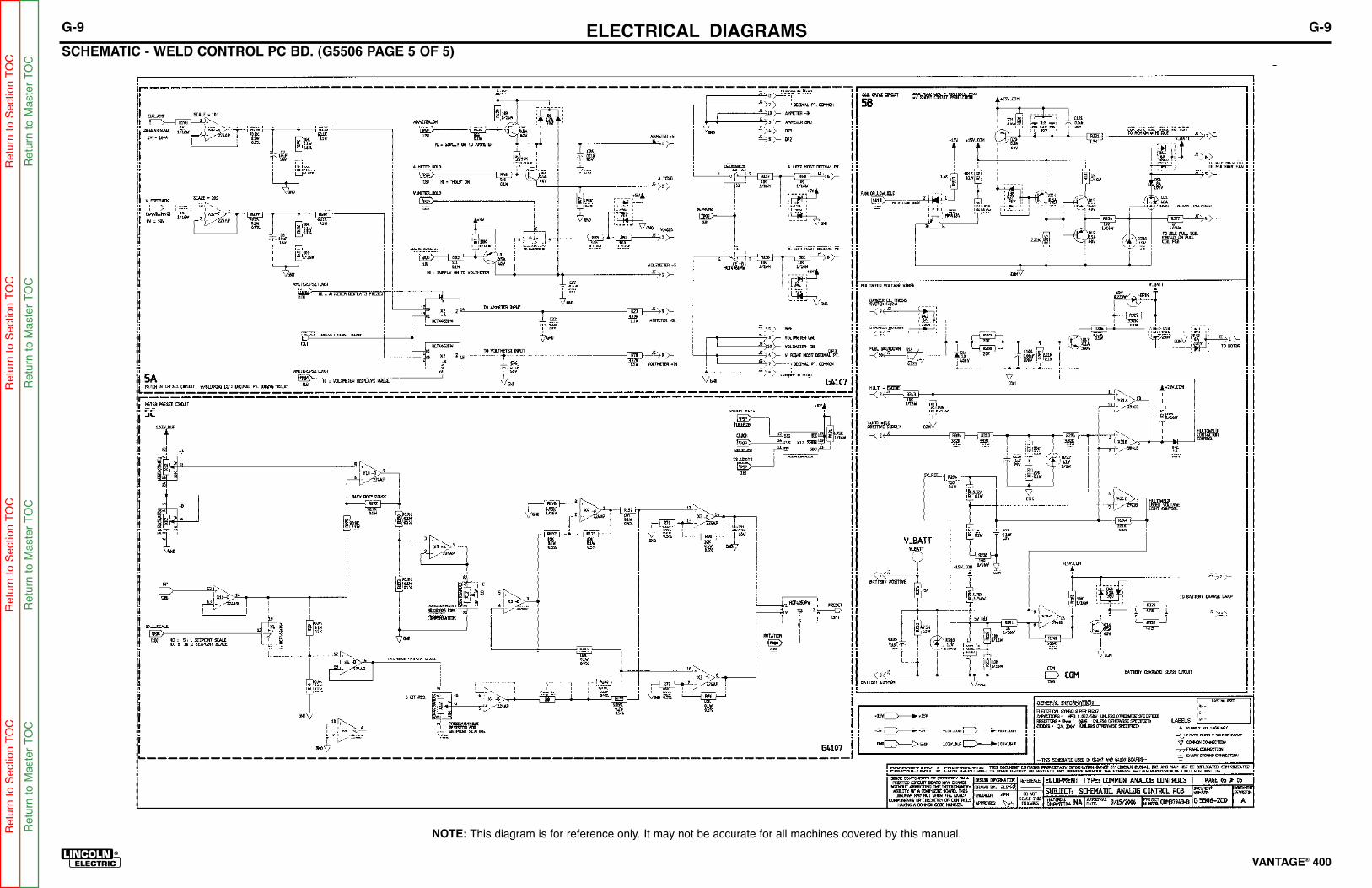
ELECTRICAL DIAGRAMS G-9
VANTAGE® 400®®
SCHEMATIC - WELD CONTROL PC BD. (G5506 PAGE 5 OF 5)
G-9
NOTE: This diagram is for reference only. It may not be accurate for all machines covered by this manual.Re
turn
to S
ection T
OC
Retu
rn t
o S
ection T
OC
Retu
rn t
o S
ectio
n T
OC
Retu
rn t
o S
ection T
OC
Re
turn
to M
aste
r T
OC
Re
turn
to M
aste
r T
OC
Retu
rn t
o M
aste
r T
OC
Retu
rn t
o M
aste
r T
OC

ELECTRICAL DIAGRAMS G-10
VANTAGE® 400®®
SCHEMATIC - IDLER PC BD (G4828-2)
G-10
NOTE: This diagram is for reference only. It may not be accurate for all machines covered by this manual.Re
turn
to S
ection T
OC
Retu
rn t
o S
ection T
OC
Retu
rn t
o S
ectio
n T
OC
Retu
rn t
o S
ection T
OC
Re
turn
to M
aste
r T
OC
Re
turn
to M
aste
r T
OC
Retu
rn t
o M
aste
r T
OC
Retu
rn t
o M
aste
r T
OC

ELECTRICAL DIAGRAMS G-11
VANTAGE® 400®®
SCHEMATIC - CHOPPER PC BD (L12717-1CO)
G-11
NOTE: This diagram is for reference only. It may not be accurate for all machines covered by this manual.Re
turn
to S
ection T
OC
Retu
rn t
o S
ection T
OC
Retu
rn t
o S
ectio
n T
OC
Retu
rn t
o S
ection T
OC
Re
turn
to M
aste
r T
OC
Re
turn
to M
aste
r T
OC
Retu
rn t
o M
aste
r T
OC
Retu
rn t
o M
aste
r T
OC

ELECTRICAL DIAGRAMS G-12
VANTAGE® 400®®
SCHEMATIC -OCV INDICATOR PC BD (G4406-2D0)
G-12
NOTE: This diagram is for reference only. It may not be accurate for all machines covered by this manual.Re
turn
to S
ection T
OC
Retu
rn t
o S
ection T
OC
Retu
rn t
o S
ectio
n T
OC
Retu
rn t
o S
ection T
OC
Re
turn
to M
aste
r T
OC
Re
turn
to M
aste
r T
OC
Retu
rn t
o M
aste
r T
OC
Retu
rn t
o M
aste
r T
OC

ELECTRICAL DIAGRAMS G-13
VANTAGE® 400®®
SCHEMATIC - BY PASS / STABILIZER PC BOARD (S22530-3D0)
G-13
NOTE: This diagram is for reference only. It may not be accurate for all machines covered by this manual.Re
turn
to S
ection T
OC
Retu
rn t
o S
ection T
OC
Retu
rn t
o S
ectio
n T
OC
Retu
rn t
o S
ection T
OC
Re
turn
to M
aste
r T
OC
Re
turn
to M
aste
r T
OC
Retu
rn t
o M
aste
r T
OC
Retu
rn t
o M
aste
r T
OC
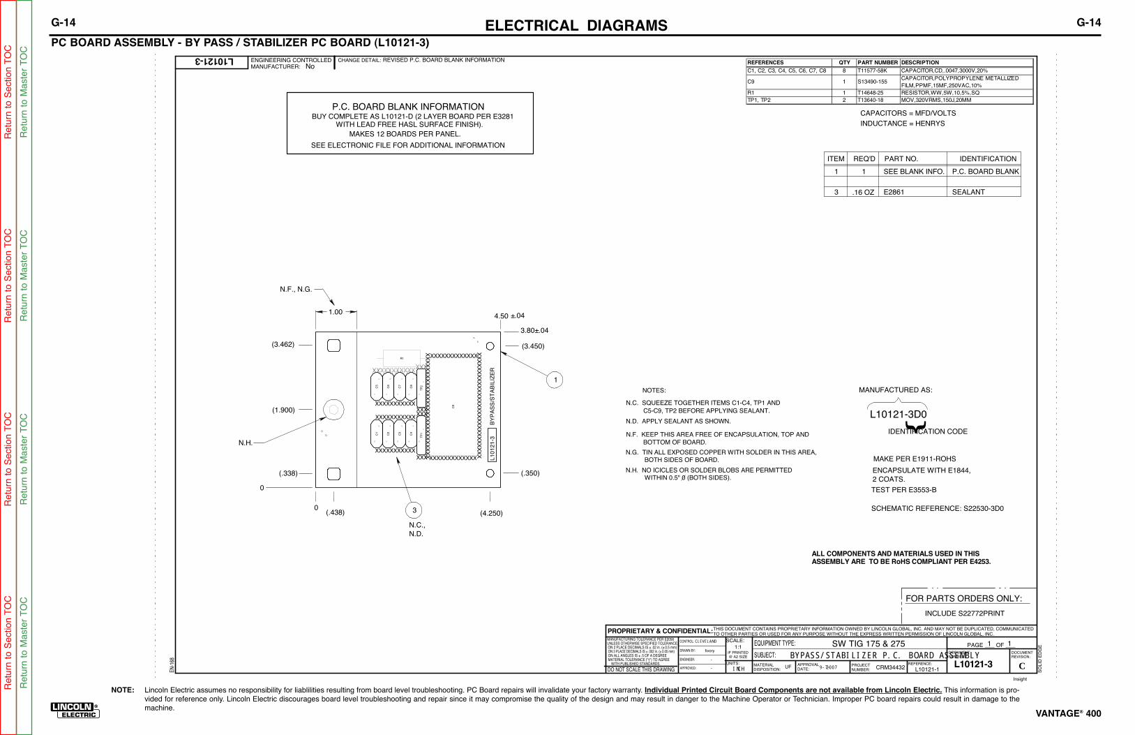
NOTE: Lincoln Electric assumes no responsibility for liablilities resulting from board level troubleshooting. PC Board repairs will invalidate your factory warranty. Individual Printed Circuit Board Components are not available from Lincoln Electric. This information is pro-vided for reference only. Lincoln Electric discourages board level troubleshooting and repair since it may compromise the quality of the design and may result in danger to the Machine Operator or Technician. Improper PC board repairs could result in damage to themachine.
ELECTRICAL DIAGRAMS G-14
VANTAGE® 400®®
PC BOARD ASSEMBLY - BY PASS / STABILIZER PC BOARD (L10121-3)
EN
-168
SO
LID
ED
GE
L10121-3
SW TIG 175 & 275
BYPASS/STABILIZER P.C. BOARD ASSEMBLY1:1
L10121-1DO NOT SCALE THIS DRAWING
EQUIPMENT TYPE:
SUBJECT:
UF CRM34432
1PAGE ___ OF ___1
ENGINEERING CONTROLLEDMANUFACTURER: No
THIS DOCUMENT CONTAINS PROPRIETARY INFORMATION OWNED BY LINCOLN GLOBAL, INC. AND MAY NOT BE DUPLICATED, COMMUNICATEDTO OTHER PARTIES OR USED FOR ANY PURPOSE WITHOUT THE EXPRESS WRITTEN PERMISSION OF LINCOLN GLOBAL, INC.PROPRIETARY & CONFIDENTIAL:
REVISED P.C. BOARD BLANK INFORMATION
tMATERIAL TOLERANCE (" ") TO AGREEWITH PUBLISHED STANDARDS.
ON ALL ANGLES IS ± .5 OF A DEGREEON 3 PLACE DECIMALS IS ± .002 in. (± 0.05 mm)ON 2 PLACE DECIMALS IS ± .02 in. (± 0.5 mm)UNLESS OTHERWISE SPECIFIED TOLERANCE:MANUFACTURING TOLERANCE PER E2056
CHANGE DETAIL:
REFERENCE:
SCALE:
MATERIALDISPOSITION:
APPROVALDATE:
PROJECTNUMBER:
DOCUMENTNUMBER:
DOCUMENTREVISION:
UNITS:
IF PRINTED@ A2 SIZE
INCH 9-7-2007
fivory
-
-
DRAWN BY:
ENGINEER:
CLEVELAND
APPROVED:
CONTROL:
CL10121-3
Insight
CAPACITORS = MFD/VOLTS
INDUCTANCE = HENRYS
1 P.C. BOARD BLANK1
ITEM REQ'D PART NO. IDENTIFICATION
3 .16 OZ E2861 SEALANT
SEE BLANK INFO.
MAKE PER E1911-ROHS
TEST PER E3553-B
L10121-3D0
MANUFACTURED AS:
IDENTIFICATION CODE
N.C. SQUEEZE TOGETHER ITEMS C1-C4, TP1 ANDC5-C9, TP2 BEFORE APPLYING SEALANT.
N.D. APPLY SEALANT AS SHOWN.
BOTTOM OF BOARD.
NOTES:
ENCAPSULATE WITH E1844,2 COATS.
N.F. KEEP THIS AREA FREE OF ENCAPSULATION, TOP AND
N.G. TIN ALL EXPOSED COPPER WITH SOLDER IN THIS AREA,BOTH SIDES OF BOARD.
WITHIN 0.5" 0 (BOTH SIDES).N.H. NO ICICLES OR SOLDER BLOBS ARE PERMITTED
SCHEMATIC REFERENCE: S22530-3D0
FOR PARTS ORDERS ONLY:
INCLUDE S22772PRINT
3
1
(.338)
(3.462)
N.C.,N.D.
0
3.80±.04
(3.450)
(.350)
(1.900)
4.50 ±.04
(.438) (4.250)0
1.00
XXXXXXXXXXXXXX
XXXXXXXXXXXXXX
XXXXXXXXXXXXXX
N.F., N.G.
N.H.
XXXXXXXXXXXXX
XXXXXXXXXXXXX
XX
XX
XX
XX
XX
XX
XX
XX
XX
XX
XX
XX
XX
XX
X
XX
XX
XX
XX
XX
XX
XX
XX
XX
XX
XX
XX
XX
XX
X
TP
1T
P2
R1
C9
C1
C2
C3
C4
C5
C6
C7
C8
L1
01
21-3
BY
PA
SS
/ST
AB
ILIZ
ER
SEE ELECTRONIC FILE FOR ADDITIONAL INFORMATION
P.C. BOARD BLANK INFORMATIONBUY COMPLETE AS L10121-D (2 LAYER BOARD PER E3281 WITH LEAD FREE HASL SURFACE FINISH).
MAKES 12 BOARDS PER PANEL.
ALL COMPONENTS AND MATERIALS USED IN THISASSEMBLY ARE TO BE RoHS COMPLIANT PER E4253.
REFERENCES QTY PART NUMBER DESCRIPTION
C1, C2, C3, C4, C5, C6, C7, C8 8 T11577-58K CAPACITOR,CD,.0047,3000V,20%
C9 1 S13490-155CAPACITOR,POLYPROPYLENE METALLIZED
FILM,PPMF,15MF,250VAC,10%
R1 1 T14648-25 RESISTOR,WW,5W,10,5%,SQ
TP1, TP2 2 T13640-18 MOV,320VRMS,150J,20MM
G-14
Re
turn
to S
ection T
OC
Retu
rn t
o S
ection T
OC
Retu
rn t
o S
ectio
n T
OC
Retu
rn t
o S
ection T
OC
Re
turn
to M
aste
r T
OC
Re
turn
to M
aste
r T
OC
Retu
rn t
o M
aste
r T
OC
Retu
rn t
o M
aste
r T
OC